JP6044403B2 - Imaging apparatus, imaging method, and imaging program - Google Patents
Imaging apparatus, imaging method, and imaging programDownload PDFInfo
- Publication number
- JP6044403B2 JP6044403B2JP2013055475AJP2013055475AJP6044403B2JP 6044403 B2JP6044403 B2JP 6044403B2JP 2013055475 AJP2013055475 AJP 2013055475AJP 2013055475 AJP2013055475 AJP 2013055475AJP 6044403 B2JP6044403 B2JP 6044403B2
- Authority
- JP
- Japan
- Prior art keywords
- image
- spot light
- imaging
- subject
- spot
- Prior art date
- Legal status (The legal status is an assumption and is not a legal conclusion. Google has not performed a legal analysis and makes no representation as to the accuracy of the status listed.)
- Expired - Fee Related
Links
Images


Classifications
- G—PHYSICS
- G01—MEASURING; TESTING
- G01B—MEASURING LENGTH, THICKNESS OR SIMILAR LINEAR DIMENSIONS; MEASURING ANGLES; MEASURING AREAS; MEASURING IRREGULARITIES OF SURFACES OR CONTOURS
- G01B11/00—Measuring arrangements characterised by the use of optical techniques
- G01B11/24—Measuring arrangements characterised by the use of optical techniques for measuring contours or curvatures
- G01B11/25—Measuring arrangements characterised by the use of optical techniques for measuring contours or curvatures by projecting a pattern, e.g. one or more lines, moiré fringes on the object
- G01B11/2518—Projection by scanning of the object
- G—PHYSICS
- G01—MEASURING; TESTING
- G01B—MEASURING LENGTH, THICKNESS OR SIMILAR LINEAR DIMENSIONS; MEASURING ANGLES; MEASURING AREAS; MEASURING IRREGULARITIES OF SURFACES OR CONTOURS
- G01B21/00—Measuring arrangements or details thereof, where the measuring technique is not covered by the other groups of this subclass, unspecified or not relevant
- G01B21/02—Measuring arrangements or details thereof, where the measuring technique is not covered by the other groups of this subclass, unspecified or not relevant for measuring length, width, or thickness
- G01B21/04—Measuring arrangements or details thereof, where the measuring technique is not covered by the other groups of this subclass, unspecified or not relevant for measuring length, width, or thickness by measuring coordinates of points
- G01B21/045—Correction of measurements
- G—PHYSICS
- G06—COMPUTING OR CALCULATING; COUNTING
- G06V—IMAGE OR VIDEO RECOGNITION OR UNDERSTANDING
- G06V10/00—Arrangements for image or video recognition or understanding
- G06V10/10—Image acquisition
- G06V10/12—Details of acquisition arrangements; Constructional details thereof
- G06V10/14—Optical characteristics of the device performing the acquisition or on the illumination arrangements
- G06V10/143—Sensing or illuminating at different wavelengths
- G—PHYSICS
- G06—COMPUTING OR CALCULATING; COUNTING
- G06V—IMAGE OR VIDEO RECOGNITION OR UNDERSTANDING
- G06V40/00—Recognition of biometric, human-related or animal-related patterns in image or video data
- G06V40/10—Human or animal bodies, e.g. vehicle occupants or pedestrians; Body parts, e.g. hands
- G06V40/107—Static hand or arm
- G06V40/11—Hand-related biometrics; Hand pose recognition
- G—PHYSICS
- G06—COMPUTING OR CALCULATING; COUNTING
- G06V—IMAGE OR VIDEO RECOGNITION OR UNDERSTANDING
- G06V40/00—Recognition of biometric, human-related or animal-related patterns in image or video data
- G06V40/10—Human or animal bodies, e.g. vehicle occupants or pedestrians; Body parts, e.g. hands
- G06V40/14—Vascular patterns
- G06V40/145—Sensors therefor
- H—ELECTRICITY
- H04—ELECTRIC COMMUNICATION TECHNIQUE
- H04N—PICTORIAL COMMUNICATION, e.g. TELEVISION
- H04N23/00—Cameras or camera modules comprising electronic image sensors; Control thereof
- H04N23/80—Camera processing pipelines; Components thereof
- H04N23/81—Camera processing pipelines; Components thereof for suppressing or minimising disturbance in the image signal generation
Landscapes
- Engineering & Computer Science (AREA)
- General Physics & Mathematics (AREA)
- Physics & Mathematics (AREA)
- Multimedia (AREA)
- Theoretical Computer Science (AREA)
- Human Computer Interaction (AREA)
- Computer Vision & Pattern Recognition (AREA)
- Health & Medical Sciences (AREA)
- General Health & Medical Sciences (AREA)
- Vascular Medicine (AREA)
- Signal Processing (AREA)
- Image Input (AREA)
- Collating Specific Patterns (AREA)
- Image Processing (AREA)
- Studio Devices (AREA)
Description
Translated fromJapanese本発明は、撮像装置、撮像方法、および撮像プログラムに関する。 The present invention relates to an imaging apparatus, an imaging method, and an imaging program.
各人特有の情報である生体情報を利用して個人の特定や照合を行う生体認証装置においては、撮像装置によって撮像された生体画像から抽出された特徴量を認証に使用することが一般的である。しかしながら、登録時に撮像した生体画像と認証時に撮像された生体画像との間で、姿勢や距離が同じになるとは限らない。そこで、特許文献1は、画像を補正する技術を開示している。 In a biometric authentication device that identifies and collates individuals using biometric information that is information unique to each person, it is common to use a feature amount extracted from a biometric image captured by the imaging device for authentication. is there. However, the posture and distance are not always the same between the biometric image captured during registration and the biometric image captured during authentication. Therefore, Patent Document 1 discloses a technique for correcting an image.
ところで、生体認証装置において使用される撮像装置は、主としてグローバルシャッター型撮像装置と、ローリングシャッター型撮像装置とに大別される。ローリングシャッター型撮像装置は、撮像領域全体を一度に撮像するグローバルシャッター型撮像装置とは異なり、撮像領域を構成する各ラインを順次撮像し、全ラインの撮像が済んだ段階で1つの画面を構成する。ローリングシャッター型撮像装置は、グローバルシャッター型撮像装置よりも安価でかつ小型化が容易であるため、特に小型の生体認証装置への搭載が期待されている。 By the way, the imaging devices used in the biometric authentication device are roughly classified into a global shutter type imaging device and a rolling shutter type imaging device. Unlike the global shutter type imaging device that captures the entire imaging area at once, the rolling shutter type imaging device sequentially captures each line that makes up the imaging area, and forms a single screen when all the lines have been imaged. To do. Since the rolling shutter type imaging device is cheaper and easier to miniaturize than the global shutter type imaging device, it is particularly expected to be mounted on a small biometric authentication device.
しかしながら、ローリングシャッター型撮像装置は撮像領域を構成する各ラインを順次撮像するため、被写体が動いていた場合に撮像画像に歪みが生じるおそれがある。特許文献1の技術では、この歪みを補正することができない。歪みが生じた画像を生体認証に利用すると、特徴点の位置が変わる等の理由により、認証精度が低下するおそれがある。 However, since the rolling shutter type imaging device sequentially captures each line constituting the imaging region, there is a possibility that the captured image may be distorted when the subject is moving. With the technique of Patent Document 1, this distortion cannot be corrected. When an image with distortion is used for biometric authentication, there is a risk that the authentication accuracy may decrease due to a change in the position of a feature point.
1つの側面では、本発明は、撮像領域を構成する各ラインを順次撮像する方式において、被写体の移動に起因する撮像画像の歪みを修正することができる撮像装置、撮像方法、および撮像プログラムを提供することを目的とする。 In one aspect, the present invention provides an imaging apparatus, an imaging method, and an imaging program capable of correcting distortion of a captured image caused by movement of a subject in a system that sequentially images each line constituting an imaging region. The purpose is to do.
1つの態様では、撮像装置は、撮像領域を構成する各ラインを順次撮像することで、該撮像領域中に存在する被写体を撮像した撮像画像を生成する画像センサと、前記被写体にスポット光を照射する複数のスポット光源と、前記画像センサが生成した撮像画像において第1のラインに対応する部分における前記スポット光の位置と、前記撮像画像において第2のラインに対応する部分における前記スポット光の位置とに基づいて、前記画像センサのセンサ面に対する前記被写体の傾きを推定する傾き推定部と、前記第1のラインにおける前記スポット光同士の距離および前記第2のラインにおける前記スポット光同士の距離に基づいて、前記傾き推定部が推定した傾きを有する被写体を撮像したときに生成されるべき画像を推定する画像推定部と、前記撮像画像における前記スポット光の位置および形状と前記推定された画像における前記スポット光の位置および形状とを比較した結果に基づいて、前記各ラインを順次撮像することに起因して生じる歪みが打ち消されるように、前記画像センサが生成した撮像画像を補正する補正処理部と、を備える。In one aspect, the imaging apparatus sequentially images each line constituting the imaging region, thereby generating animage sensor that captures an image of a subject existing in the imaging region,and irradiating the subject with spot light. A plurality of spot light sources,a position of the spot light in a portion corresponding to a first linein a captured imagegenerated by the image sensor,anda position of the spot light in a portion corresponding to a second line in the captured image And an inclination estimation unit that estimates the inclination of the subject with respect tothe sensor surface of the image sensor,and the distance between the spot lights on the first line and the distance between the spot lights on the second line. based on the image estimation for estimating an image to be generated when capturing an object having an inclinationof the slope estimating unit has estimated If, based on the result of comparing theposition and shape of the spot light inposition and shape as the estimated imageof the spot light inthe captured image,distortion caused by the sequentially imaging the respective lines A correction processing unit that corrects a captured imagegenerated by the image sensor so that the image is canceled .
被写体の移動に起因する撮像画像の歪みを修正することができる。 The distortion of the captured image caused by the movement of the subject can be corrected.
実施例の説明に先立って、グローバルシャッター型撮像装置およびローリングシャッター型撮像装置の概略について説明する。図1(a)は、グローバルシャッター型撮像装置について説明するための図である。図1(b)は、ローリングシャッター型撮像装置について説明するための図である。 Prior to the description of the embodiments, an outline of a global shutter type imaging device and a rolling shutter type imaging device will be described. FIG. 1A is a diagram for explaining a global shutter type imaging apparatus. FIG. 1B is a diagram for explaining a rolling shutter type imaging apparatus.
図1(a)を参照して、グローバルシャッター型撮像装置は、画面全体の全てのラインを一度に同時に撮像(露光)する。このため、露光時間が十分に短ければ、被写体が動いても歪みなく撮像が可能である。これに対して、図1(b)を参照して、ローリングシャッター型撮像装置は、撮像領域を構成する各ラインを順次撮像(露光)していく。その結果、各ラインの露光タイミングが少しずつずれる。図1(b)の例では、撮像領域の一番上のラインから一番下のラインに向けて順に露光するタイミングが少しずつずれている。この結果、上から下まで全ラインの露光が完了するまでの期間中に被写体が動いてしまった場合は、露光したラインごとに被写体の位置が変わることになる。それにより、撮像した撮像画像に歪みが生じる。 Referring to FIG. 1A, the global shutter type imaging device images (exposes) all the lines of the entire screen at the same time. For this reason, if the exposure time is sufficiently short, imaging can be performed without distortion even if the subject moves. On the other hand, referring to FIG. 1B, the rolling shutter type imaging apparatus sequentially captures (exposes) each line constituting the imaging region. As a result, the exposure timing of each line is slightly shifted. In the example of FIG. 1B, the exposure timing is shifted little by little from the uppermost line to the lowermost line in the imaging region. As a result, if the subject moves during the period until the exposure of all lines is completed from top to bottom, the position of the subject changes for each exposed line. Thereby, distortion occurs in the captured image.
図2は、撮像装置に対して近づきつつある手のひらを、ローリングシャッター型撮像装置で撮像する様子を表す図である。図2の例では、撮像装置のライン走査方向は、指先から手首に向かっている。つまり、撮像装置は、指先から手首に向かって1ラインずつ露光しながら撮像する。それにより、撮像装置に近づきつつある手のひらを撮像した場合、露光が早く行われたライン(指先側)は遠方の手のひらが映り、露光が遅く行われたライン(手首側)は近くの手のひらが映る。 FIG. 2 is a diagram illustrating a state in which a palm approaching the imaging apparatus is imaged by a rolling shutter type imaging apparatus. In the example of FIG. 2, the line scanning direction of the imaging device is from the fingertip toward the wrist. That is, the imaging device captures an image while exposing one line at a time from the fingertip to the wrist. As a result, when the palm approaching the imaging device is imaged, the far-expanded line (fingertip side) reflects the distant palm, and the slow-exposure line (wrist side) reflects the nearby palm. .
図3は、静止した手のひらを撮像したとみなして模擬した図である。図3を参照して、指先は撮像装置に対して遠方で露光しており、手首に近い位置は撮像装置に近い位置で露光しているため、静止した手のひらで模擬すると、実際の手のひらに比べて斜め縦方向に伸びた手のひらを撮像した場合と近似した画像になる。なお、各ラインの伸び方は均一ではなく、指先ほど大きく伸びる傾向にある。 FIG. 3 is a diagram simulating that a stationary palm is imaged. Referring to FIG. 3, the fingertip is exposed at a distance from the imaging device, and the position close to the wrist is exposed at a position close to the imaging device. Therefore, when simulated with a stationary palm, the fingertip is compared with the actual palm. Thus, the image is similar to the case where the palm stretched obliquely in the vertical direction is imaged. In addition, the way of extending each line is not uniform, and tends to extend greatly as the fingertips.
これに対して、図4は、実際に静止した手のひらを撮像装置に対して斜めにかざして撮像した場合の図である。図3と図4とを比較すると、手のひらの映りかたが大きく異なっていることがわかる。ローリングシャッター型撮像装置に手のひらを近づけつつ撮像した手のひらの画像は、実際に静止した手のひらを撮像した画像よりも、ローリングシャッター型の撮像装置の走査方向に大きく伸びた手のひらとなる。 On the other hand, FIG. 4 is a diagram in a case where an actually stationary palm is imaged while being held obliquely with respect to the imaging apparatus. Comparing FIG. 3 and FIG. 4, it can be seen that the way the palm is reflected is greatly different. The image of the palm imaged while bringing the palm close to the rolling shutter type imaging device becomes a palm greatly extending in the scanning direction of the rolling shutter type imaging device than the image of the actually stationary palm imaged.
このように、本来の手のひらの画像よりも伸びて歪んだ画像を用いて生体認証を行うと、静止して撮像した場合の登録画像と特徴量が合致しなくなる。その結果、認証精度が悪化することになる。以下の実施例では、被写体の移動に起因する撮像画像の歪みを修正することができる撮像装置、撮像方法、および撮像プログラムについて説明する。 In this way, if biometric authentication is performed using an image that is longer than the original palm image and distorted, the registered image and the feature amount when captured stillly do not match. As a result, authentication accuracy deteriorates. In the following embodiments, an imaging apparatus, an imaging method, and an imaging program that can correct distortion of a captured image caused by movement of a subject will be described.
図5(a)は、実施例1に係る生体認証装置100のハードウェア構成を説明するためのブロック図である。図5(a)を参照して、生体認証装置100は、CPU101、RAM102、記憶装置103、表示装置104、画像センサ105、複数のスポット光源106、拡散光源107などを備える。 FIG. 5A is a block diagram for explaining a hardware configuration of the
CPU(Central Processing Unit)101は、中央演算処理装置である。CPU101は、1以上のコアを含む。RAM(Random Access Memory)102は、CPU101が実行するプログラム、CPU101が処理するデータなどを一時的に記憶する揮発性メモリである。記憶装置103は、不揮発性記憶装置である。記憶装置103として、例えば、ROM(Read Only Memory)、フラッシュメモリなどのソリッド・ステート・ドライブ(SSD)、ハードディスクドライブに駆動されるハードディスクなどを用いることができる。記憶装置103は、撮像プログラムおよび生体認証プログラムを記憶している。 A CPU (Central Processing Unit) 101 is a central processing unit. The
表示装置104は、液晶ディスプレイ、エレクトロルミネッセンスパネルなどであり、生体認証処理の結果などを表示する。画像センサ105は、撮像領域を構成する各ラインを順次撮像することで、該撮像領域中に存在する被写体を撮像した撮像画像を生成するローリングシャッター型のセンサである。本実施例においては、画像センサ105は、一例としてユーザの手のひらの撮像画像を生成する。スポット光源106は、被写体の一部にスポット光を照射する光源であり、一例として発光ダイオードである。本実施例においては、一例として、撮像画像において矩形状のスポット光が現れる。拡散光源107は、手のひらの全体に光を照射する拡散光源であり、一例として近赤外線照射ランプである。 The
図5(b)は、画像センサ105およびスポット光源106の位置関係を説明するための上面図である。図5(b)を参照して、複数のスポット光源106は、画像センサ105の周囲に配置されている。例えば、画像センサ105は矩形の基板の中央部に配置され、各スポット光源106は当該基板の各角部に配置されている。なお、図5(b)においては、拡散光源107については省略している。 FIG. 5B is a top view for explaining the positional relationship between the
記憶装置103に記憶されている撮像プログラムおよび生体認証プログラムは、実行可能にRAM102に展開される。CPU101は、RAM102に展開された撮像プログラムおよび生体認証プログラムを実行する。それにより、生体認証装置100による画像補正処理および生体認証処理が実行される。画像補正処理は、画像の歪みを補正する処理である。生体認証処理は、認証時に取得された照合用特徴データと、あらかじめ登録された登録特徴データとの照合によって被認証ユーザを特定する処理である。 The imaging program and biometric authentication program stored in the
図6は、撮像プログラムおよび生体認証プログラムの実行によって実現される各機能のブロック図である。撮像プログラムの実行によって、生体認証装置100には、撮像装置10および認証処理装置20が実現される。撮像装置10は、同期制御部11、撮像部12、第1画像記憶部13、スポット光抽出部14、位置形状検出部15、歪み情報算出部16、第2画像記憶部17、および歪み補正部18として機能する。また、画像センサ105、第1光源106および第2光源107も撮像装置10として機能する。認証処理装置20は、生体特徴抽出部21、生体特徴照合部22、登録特徴データ記憶部23、および認証結果出力部24として機能する。 FIG. 6 is a block diagram of each function realized by executing the imaging program and the biometric authentication program. By executing the imaging program, the
図7は、生体認証装置100によって実行されるフローチャートの一例を説明するための図である。図7のフローチャートにおいて、ステップS1〜ステップS5が撮像装置10によって実行される撮像処理を表し、ステップS6が認証処理装置20によって実行される生体認証処理を表す。図6および図7を参照して、同期制御部11は、スポット光源106を点灯し、撮像部12に撮像を指示する。それにより、スポット光源106の点灯に同期して画像センサ105がユーザの手のひらの画像をラインごとに順次撮像する。取得された撮像画像は、第1画像として第1画像記憶部13によって記憶される(ステップS1)。 FIG. 7 is a diagram for explaining an example of a flowchart executed by the
次に、同期制御部11は、拡散光源107を点灯し、撮像部12に撮像を指示する。それにより、拡散光源107の点灯に同期して画像センタ105がユーザの手のひらの画像をラインごとに順次撮像する。取得された撮像画像は、第2画像として第2画像記憶部17によって記憶される(ステップS2)。拡散光源として近赤外線を用いた場合には、生体の皮下の静脈の走行パターンを含む画像を得ることができる。次に、スポット光抽出部14は、第1画像記憶部13に記憶された第1画像からスポット光を抽出する(ステップS3)。次に、位置形状検出部15および歪み情報算出部16は、第1画像における各スポット光の位置および形状から、画像の歪み情報を算出する(ステップS4)。 Next, the
具体的には、位置形状検出部15は、第1画像で所定のラインに対応する部分において隣り合ったスポット光の位置から、当該スポット光のラインを撮像したときの被写体の傾きを推定する。例えば、位置形状検出部15は、各ラインにおいて隣り合うスポット光同士の距離を検出することによって、当該ラインを撮像したときの被写体の距離が得られ、それらの距離を比較することによって手のひらの傾きを推定する。 Specifically, the position
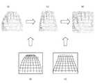
図8(a)は、静止した手のひらが画像センサ105のセンサ面に対して斜めにかざされた場合の各スポット光の位置を表す図である。図8(a)を参照して、各ラインにおいて隣り合うスポット光同士の距離が異なっている。撮像中に手のひらが移動する場合(手のひらが画像センサに近づく場合)には、図8(b)のように走査方向におけるスポット光同士の距離が図8(a)と異なっている。しかしながら、各ラインにおけるスポット光同士の距離が得られれば、走査方向におけるスポット光同士の距離が異なっていても、手のひらの傾きは得られる。 FIG. 8A is a diagram illustrating the position of each spot light when the stationary palm is held obliquely with respect to the sensor surface of the
ライン間のスポット光の位置を検出し、検出された位置が、静止した被写体を撮像したスポット光の位置と異なっていれば、ローリングシャッターの歪みが生じていると判定することができる。位置形状検出部15は、スポット光の位置を、ローリングシャッターの歪みが無いスポット光の位置になるように各スポット光の位置を補正する係数(ローリングシャッターの歪みを打ち消すための補正係数)を算出する。 If the position of the spot light between the lines is detected and the detected position is different from the position of the spot light obtained by imaging the stationary subject, it can be determined that the rolling shutter is distorted. The position
図9(a)は、位置形状検出部15によって検出された傾きを有して静止してかざされた手のひらにスポット光を照射したと仮定した場合に生成されるべき撮像画像におけるスポット光の位置および形状を表す図である。位置形状検出部15は、第1画像の各ラインにおいて隣り合うスポット光同士の距離を用いて、図9(a)の位置および形状を推定する。図9(b)は、被写体が動いたことによる歪みの影響を受けた撮像画像(第1画像)におけるスポット光の位置および形状を表す図である。 FIG. 9A shows the position of the spot light in the captured image that is to be generated on the assumption that the spot light is irradiated to the palm held stationary with the inclination detected by the position
歪み情報算出部16は、図9(c)で表されるように、スポット光の形状の歪みから、撮像画像全体の歪み情報を内挿および外挿によって算出する。それにより、図9(e)で表される被写体が動いたことによる歪みの影響を受けて歪んだ格子が算出される。なお、図9(e)の格子は、図9(d)で表される手のひらを静止して斜めにかざしたときの歪みの影響を含まない格子が歪んだ格子である。図9(e)の歪んだ格子が画像歪み情報として用いられる。 As shown in FIG. 9C, the distortion
再度、図6および図7を参照して、歪み補正部18は、ステップS3で算出された画像歪み情報を用いて、第2画像記憶部17に記憶された第2画像の歪みを補正する。図10(a)は、第2画像の一例を表す図である。第2画像は、被写体の傾きおよび歪みの影響を含む画像である。歪み補正部18は、得られた画像歪み情報(図10(b))を用いて、ローリングシャッターに起因する第2画像の歪みが打ち消されるような補正を行う。具体的には、図10(b)で表される歪みの格子が図10(d)で表される歪みの影響を含まない格子となるように、第2画像の歪みを補正する。それにより、図10(c)の画像が得られる。歪み補正部18は、手のひらを静止して斜めにかざしたときの歪みの影響を含まない格子(図10(d))を用いて、図10(c)の画像における手のひらの傾きを補正する。それにより、手のひらを画像センサ105のセンサ面に対して平行に静止した状態を表す第3画像(図10(e))が生成される(ステップS5)。 6 and 7 again, the
認証処理装置20は、ステップS5で得られた第3画像を用いて、生体認証処理を行う(ステップS6)。具体的には、生体特徴抽出部21が第3画像から生体特徴を抽出する。次に、生体特徴照合部22は、登録特徴データ記憶部23に登録されている登録特徴データと、生体特徴抽出部21が抽出した生体特徴との類似度を算出し、当該類似度がしきい値以上であれば照合成功と判定する。生体特徴照合部22による照合の結果は、認証結果出力部24によって表示装置104に出力される。以上の処理が完了すると、フローチャートの実行が終了する。 The
本実施例によれば、撮像領域を構成する各ラインを順次撮像するローリングシャッター型の撮像装置において、被写体の移動に伴う撮像画像の歪みを修正することができる。それにより、生体認証の認証精度が向上する。 According to the present embodiment, in a rolling shutter type imaging apparatus that sequentially images each line constituting the imaging area, it is possible to correct the distortion of the captured image accompanying the movement of the subject. Thereby, the authentication accuracy of biometric authentication is improved.
(他の例)
撮像画像におけるスポット光の位置や大きさは、撮像機器の個体差に起因して異なることがある。この個体差に起因する映り方の相違は、あらかじめ個体差に起因する映り方の相違を補正するためのキャリブレーション処理によって補正しておいてもよい。(Other examples)
The position and size of the spot light in the captured image may be different due toindividual differences among the imaging devices. The difference in the appearance due to the individual difference may be corrected in advance by a calibration process for correcting the difference in the appearance due to the individual difference.
上記実施例においては、矩形状のスポット光を用いたが、それに限られない。円形、楕円形などの他の形状のスポット光であっても、撮像画像におけるスポット光の形状を用いて、被写体が動いたことによる歪みの影響を受けて歪んだ格子を算出することができる。上記実施例においては、被写体として手のひらを用いたが、他の生体を被写体として用いてもよい。 In the above embodiment, rectangular spot light is used, but the present invention is not limited to this. Even for spot lights having other shapes such as a circle and an ellipse, a distorted lattice can be calculated using the shape of the spot light in the captured image due to the influence of distortion caused by the movement of the subject. In the above embodiment, the palm is used as the subject, but another living body may be used as the subject.
画像センサ105による撮像の際に被写体が回転動作を行うと、撮像画像におけるスポット光の大きさに相違が現れる。そこで、スポット光の大きさにしきい値以上の相違が現れた場合に、被写体の回転動作を補正してもよい。被写体が回転動作を行うと、図11(a)および図11(b)で表すように、撮像画像におけるスポット光や手のひらが斜め方向に歪んだように映ることになる。歪み補正部18は、図11(a)のスポット光画像に基づいて図11(c)で表す補正用格子パターンを生成してもよい。 If the subject rotates during imaging by the
図12(a)は、回転動作の影響を含む第2画像の一例を表す図である。歪み補正部18は、得られた画像歪み情報(図12(b))を用いて、ローリングシャッターに起因する第2画像の歪みを補正する。それにより、図12(c)の画像が得られる。歪み補正部18は、手のひらを静止して斜めにかざしたときの歪みの影響を含まない格子(図12(d))を用いて、図12(c)の画像を補正する。それにより、手のひらを画像センサ105に対して平行に静止した状態を表す第3画像(図12(e))が生成される。 FIG. 12A is a diagram illustrating an example of the second image including the influence of the rotation operation. The
また、スポット光源106および拡散光源107は、単一の光源から得られた光源であってもよい。具体的には、図13を参照して、電子的な制御手段、光学的な分光手段、機械的な移動回転手段などによって、単一の光源からの光を分光することによってスポット光源および拡散光源を生成してもよい。 Further, the
実施例1では、拡散光源107が点灯せずにスポット光源106が点灯した状態で撮像された第1画像と、スポット光源106が点灯せずに拡散光源107が点灯した状態で撮像された第2画像とを用いたが、それに限られない。スポット光源106および拡散光源107の両方が点灯した状態で撮像された画像を用いてもよい。以下、実施例2について説明する。 In the first embodiment, the first image captured in a state where the
図14は、実施例2に係る撮像プログラムおよび生体認証プログラムの実行によって実現される各機能のブロック図である。図14を参照して、図6と異なる点は、第1画像記憶部13の代わりに画像記憶部13aが設けられ、第2画像記憶部17が設けられていない点である。 FIG. 14 is a block diagram of each function realized by executing the imaging program and the biometric authentication program according to the second embodiment. Referring to FIG. 14, the difference from FIG. 6 is that
図15は、本実施例に係るフローチャートの一例を説明するための図である。図14および図15を参照して、同期制御部11は、スポット光源106および拡散光源107を点灯し、撮像部12に撮像を指示する。それにより、スポット光および拡散光が照射された状態で画像センサ105がユーザの手のひらの画像をラインごとに順次撮像する。取得された撮像画像は、画像記憶部13aによって記憶される(ステップS11)。 FIG. 15 is a diagram for explaining an example of a flowchart according to the present embodiment. Referring to FIGS. 14 and 15,
次に、スポット光抽出部14は、画像記憶部13aに記憶された撮像画像からスポット光を抽出する(ステップS12)。具体的には、輝度値、波長などに基づいて、撮像画像におけるスポット光を検出することができる。次に、位置形状検出部15および歪み情報算出部16は、撮像画像における各スポット光の位置および形状から、画像の歪み情報を算出する(ステップS13)。ステップS13は、図7のステップS4と同様の処理である。次に、歪み補正部18は、ステップS13で算出された画像歪み情報を用いて、画像記憶部13aに記憶された撮像画像の歪みを補正する(ステップS14)ステップS14は、図7のステップS5と同様の処理である。次に、認証処理装置20は、ステップS14で得られた補正後の画像を用いて、生体認証処理を行う(ステップS15)。ステップS15は、図7のステップS6と同様の処理である。以上の処理が完了すると、フローチャートの実行が終了する。 Next, the spot
本実施例によれば、スポット光および拡散光の両方を照射した状態で得られる撮像画像を用いて、被写体の移動に伴う撮像画像の歪みを修正することができる。また、複数枚の撮像画像を生成する必要がないため、被写体の移動の影響をより抑制することができる。 According to the present embodiment, it is possible to correct the distortion of the captured image that accompanies the movement of the subject by using the captured image that is obtained in a state where both spot light and diffused light are irradiated. In addition, since it is not necessary to generate a plurality of captured images, the influence of the movement of the subject can be further suppressed.
以上、本発明の実施例について詳述したが、本発明は係る特定の実施例に限定されるものではなく、特許請求の範囲に記載された本発明の要旨の範囲内において、種々の変形・変更が可能である。 Although the embodiments of the present invention have been described in detail above, the present invention is not limited to such specific embodiments, and various modifications and changes can be made within the scope of the gist of the present invention described in the claims. It can be changed.
10 撮像装置
11 同期制御部
12 撮像部
13 第1画像記憶部
14 スポット光抽出部
15 位置形状検出部
16 歪み情報算出部
17 第2画像記憶部
18 歪み補正部
20 認証処理装置
21 生体特徴抽出部
22 生体特徴照合部
23 登録特徴データ記憶部
24 認証結果出力部
100 生体認証装置
105 画像センサ
106 スポット光源
107 拡散光源DESCRIPTION OF
Claims (7)
Translated fromJapanese前記被写体にスポット光を照射する複数のスポット光源と、
前記画像センサが生成した撮像画像において第1のラインに対応する部分における前記スポット光の位置と、前記撮像画像において第2のラインに対応する部分における前記スポット光の位置とに基づいて、前記画像センサのセンサ面に対する前記被写体の傾きを推定する傾き推定部と、
前記第1のラインにおける前記スポット光同士の距離および前記第2のラインにおける前記スポット光同士の距離に基づいて、前記傾き推定部が推定した傾きを有する被写体を撮像したときに生成されるべき画像を推定する画像推定部と、
前記撮像画像における前記スポット光の位置および形状と前記推定された画像における前記スポット光の位置および形状とを比較した結果に基づいて、前記各ラインを順次撮像することに起因して生じる歪みが打ち消されるように、前記画像センサが生成した撮像画像を補正する補正処理部と、を備えることを特徴とする撮像装置。Animage sensor that captures images of a subject existing in the imaging region by sequentially capturing the lines that form the imaging region;
A plurality of spot light sources for irradiating the subject with spot light;
The position of the spot light in a portion corresponding to the first line in the captured imageby the image sensor isgenerated, based on theposition of the spot light in the portion corresponding to the second line in the captured image,the image A tilt estimator that estimates the tilt of the subjectrelative to the sensor surface of the sensor ;
An image to be generated when a subject havingan inclinationestimated by the inclination estimation unit is imagedbased on the distance between the spot lights on the first line and the distance between the spot lights on the second line. An image estimation unit for estimating
Based on the result of comparing theposition and shape of the spot light inposition and shape as the estimated imageof the spot light inthe captured image,distortion canceled caused by the sequentially imaging the respective lines And a correction processing unit that corrects the captured imagegenerated by the image sensor .
前記傾き推定部は、前記スポット光源が前記被写体にスポット光を照射した状態で得られた撮像画像に基づいて前記被写体の傾きを推定し、
前記補正処理部は、前記拡散光源が前記被写体に光を照射した状態で得られた撮像画像を補正することを特徴とする請求項1記載の撮像装置。A diffusion light source for irradiating the entire subject with light;
The tilt estimation unit estimates the tilt of the subject based on a captured image obtained in a state where the spot light source irradiates the subject with spot light,
The imaging apparatus according toclaim 1 , wherein the correction processing unit corrects a captured image obtained in a state where the diffusion light source irradiates the subject with light.
前記傾き推定部は、前記スポット光源および前記拡散光源が前記被写体に光を照射した状態で得られた撮像画像において、輝度値または反射光の波長に基づいて前記スポット光を検出することを特徴とする請求項1記載の撮像装置。A diffusion light source for irradiating the entire subject with light;
The inclination estimation unit detects the spot light based on a luminance value or a wavelength of reflected light in a captured image obtained by irradiating the subject with light from the spot light source and the diffuse light source.The imaging apparatus according toclaim 1 .
画像センサを用いて、撮像領域を構成する各ラインを順次撮像することで、該撮像領域中に存在する前記被写体を撮像した撮像画像を生成し、
前記画像センサが生成した撮像画像において第1のラインに対応する部分における前記スポット光の位置と、前記撮像画像において第2のラインに対応する部分における前記スポット光の位置とに基づいて、前記画像センサのセンサ面に対する前記被写体の傾きを推定し、
前記第1のラインにおける前記スポット光同士の距離および前記第2のラインにおける前記スポット光同士の距離に基づいて推定した傾きを有する被写体を撮像したときに生成されるべき画像を推定し、
前記撮像画像における前記スポット光の位置および形状と前記推定された画像における前記スポット光の位置および形状とを比較した結果に基づいて、前記各ラインを順次撮像することに起因して生じる歪みが打ち消されるように、前記画像センサが生成した撮像画像を補正する、ことを特徴とする撮像方法。Irradiate the subject with spot light from multiple spot light sources,
Using the image sensor, by sequentially imaging each line constituting the imaging regionto generate a captured image captured withthe object present in the imagingarea,
Theposition of the spot light in a portion corresponding to the first line in the captured imageby the image sensor is generated, based on theposition of the spot light in the portion corresponding to the second line in the captured image,the image Estimating the inclination of the subjectrelative to the sensor surface of the sensor ;
Estimating an image to be generated when a subject havingan inclinationestimated based on a distance between the spot lights in the first line and a distance between the spot lights in the second line is captured;
Based on the result of comparing theposition and shape of the spot light inposition and shape as the estimated imageof the spot light inthe captured image,distortion canceled caused by the sequentially imaging the respective lines The imaging method is characterized in that the captured imagegenerated by the image sensor is corrected.
コンピュータに、
前記画像センサが生成した撮像画像において第1のラインに対応する部分における前記スポット光の位置と、前記撮像画像において第2のラインに対応する部分における前記スポット光の位置とに基づいて、前記画像センサのセンサ面に対する前記被写体の傾きを推定するステップと、
前記第1のラインにおける前記スポット光同士の距離および前記第2のラインにおける前記スポット光同士の距離に基づいて推定した傾きを有する被写体を撮像したときに生成されるべき画像を推定するステップと、
前記撮像画像における前記スポット光の位置および形状と前記推定された画像における前記スポット光の位置および形状とを比較した結果に基づいて、前記各ラインを順次撮像することに起因して生じる歪みが打ち消されるように、前記画像センサが生成した撮像画像を補正するステップと、を実行させることを特徴とする撮像プログラム。An imaging programthat uses an image sensor to sequentially capture each line that constitutes an imaging region, thereby generating a captured image that capturesan object thatis presentin the imaging region andis irradiated with spot light from a plurality of spot light sources. There,
On the computer,
Theposition of the spot light in a portion corresponding to the first line in the captured imageby the image sensor is generated, based on theposition of the spot light in the portion corresponding to the second line in the captured image,the image Estimating the inclination of the subjectrelative to the sensor surface of the sensor ;
Estimating an image to be generated when imaging a subject havingan inclinationestimated based on a distance between the spot lights in the first line and a distance between the spot lights in the second line ;
Based on the result of comparing theposition and shape of the spot light inposition and shape as the estimated imageof the spot light inthe captured image,distortion canceled caused by the sequentially imaging the respective lines And a step of correcting the captured imagegenerated by the image sensor .
Priority Applications (3)
| Application Number | Priority Date | Filing Date | Title |
|---|---|---|---|
| JP2013055475AJP6044403B2 (en) | 2013-03-18 | 2013-03-18 | Imaging apparatus, imaging method, and imaging program |
| EP13196878.6AEP2782327B1 (en) | 2013-03-18 | 2013-12-12 | Imaging device, imaging method, and imaging program |
| US14/108,738US9342726B2 (en) | 2013-03-18 | 2013-12-17 | Imaging device, imaging method, and non-transitory computer-readable medium |
Applications Claiming Priority (1)
| Application Number | Priority Date | Filing Date | Title |
|---|---|---|---|
| JP2013055475AJP6044403B2 (en) | 2013-03-18 | 2013-03-18 | Imaging apparatus, imaging method, and imaging program |
Publications (2)
| Publication Number | Publication Date |
|---|---|
| JP2014183393A JP2014183393A (en) | 2014-09-29 |
| JP6044403B2true JP6044403B2 (en) | 2016-12-14 |
Family
ID=49765862
Family Applications (1)
| Application Number | Title | Priority Date | Filing Date |
|---|---|---|---|
| JP2013055475AExpired - Fee RelatedJP6044403B2 (en) | 2013-03-18 | 2013-03-18 | Imaging apparatus, imaging method, and imaging program |
Country Status (3)
| Country | Link |
|---|---|
| US (1) | US9342726B2 (en) |
| EP (1) | EP2782327B1 (en) |
| JP (1) | JP6044403B2 (en) |
Families Citing this family (5)
| Publication number | Priority date | Publication date | Assignee | Title |
|---|---|---|---|---|
| JP6369078B2 (en)* | 2014-03-20 | 2018-08-08 | 富士通株式会社 | Image correction apparatus, image correction method, and computer program for image correction |
| FR3028980B1 (en)* | 2014-11-20 | 2017-01-13 | Oberthur Technologies | METHOD AND DEVICE FOR AUTHENTICATING A USER |
| WO2016204417A1 (en)* | 2015-06-15 | 2016-12-22 | 서울바이오시스 주식회사 | Hyper-spectral image measurement device and calibration method therefor, photographing module and device for skin diagnosis, skin diagnosis method, and skin image processing method |
| US11944887B2 (en)* | 2018-03-08 | 2024-04-02 | Sony Corporation | Information processing device and information processing method |
| JP7513451B2 (en)* | 2020-07-22 | 2024-07-09 | 株式会社日立製作所 | Biometric authentication device and method |
Family Cites Families (18)
| Publication number | Priority date | Publication date | Assignee | Title |
|---|---|---|---|---|
| US5978041A (en)* | 1994-10-24 | 1999-11-02 | Hitachi, Ltd. | Image display system |
| US20040218069A1 (en)* | 2001-03-30 | 2004-11-04 | Silverstein D Amnon | Single image digital photography with structured light for document reconstruction |
| GB0118242D0 (en)* | 2001-07-26 | 2001-09-19 | Lettington A H P | Scanning apparatus |
| JP2005092629A (en)* | 2003-09-18 | 2005-04-07 | Brother Ind Ltd | Image processing apparatus and imaging apparatus |
| WO2005069212A1 (en) | 2004-01-13 | 2005-07-28 | Fujitsu Limited | Authenticator using organism information |
| JP4644540B2 (en) | 2005-06-28 | 2011-03-02 | 富士通株式会社 | Imaging device |
| KR101331543B1 (en)* | 2006-03-14 | 2013-11-20 | 프라임센스 엘티디. | Three-dimensional sensing using speckle patterns |
| JP4708232B2 (en)* | 2006-03-16 | 2011-06-22 | 富士通株式会社 | Imaging device |
| JP5012236B2 (en)* | 2007-06-12 | 2012-08-29 | 株式会社ニコン | Digital camera |
| US8018649B2 (en)* | 2008-01-22 | 2011-09-13 | Flir Systems Ab | IR camera |
| JP5526638B2 (en)* | 2008-10-30 | 2014-06-18 | 株式会社Jvcケンウッド | Wireless image transmission apparatus and wireless image transmission method |
| KR101544033B1 (en)* | 2008-12-31 | 2015-08-12 | 삼성전자주식회사 | Digital camera and control method thereof |
| FR2940841B1 (en)* | 2009-01-06 | 2011-04-22 | Dxo Labs | IMAGE CAPTURE SYSTEM AND USE THEREOF FOR IMPROVING QUALITY OF ACQUIRED IMAGES |
| EP2392259A1 (en) | 2009-01-30 | 2011-12-07 | Fujitsu Frontech Limited | Authentication device, imaging device, authentication method, and authentication program |
| JP4915424B2 (en)* | 2009-02-19 | 2012-04-11 | ソニー株式会社 | Image processing apparatus, camera motion component calculation method, image processing program, and recording medium |
| JP4915423B2 (en)* | 2009-02-19 | 2012-04-11 | ソニー株式会社 | Image processing apparatus, focal plane distortion component calculation method, image processing program, and recording medium |
| KR101214806B1 (en)* | 2010-05-11 | 2012-12-24 | 가부시키가이샤 사무코 | Apparatus and method for defect inspection of wafer |
| JP5751019B2 (en)* | 2011-05-30 | 2015-07-22 | 富士通株式会社 | Biological information processing apparatus, biological information processing method, and biological information processing program |
- 2013
- 2013-03-18JPJP2013055475Apatent/JP6044403B2/ennot_activeExpired - Fee Related
- 2013-12-12EPEP13196878.6Apatent/EP2782327B1/enactiveActive
- 2013-12-17USUS14/108,738patent/US9342726B2/ennot_activeExpired - Fee Related
Also Published As
| Publication number | Publication date |
|---|---|
| EP2782327A3 (en) | 2017-11-15 |
| JP2014183393A (en) | 2014-09-29 |
| EP2782327B1 (en) | 2020-04-15 |
| US20140267761A1 (en) | 2014-09-18 |
| US9342726B2 (en) | 2016-05-17 |
| EP2782327A2 (en) | 2014-09-24 |
Similar Documents
| Publication | Publication Date | Title |
|---|---|---|
| JP6044403B2 (en) | Imaging apparatus, imaging method, and imaging program | |
| JP6089872B2 (en) | Image correction apparatus, image correction method, and biometric authentication apparatus | |
| ES3032510T3 (en) | Systems and methods for performing fingerprint based user authentication using imagery captured using mobile devices | |
| US9672406B2 (en) | Touchless fingerprinting acquisition and processing application for mobile devices | |
| JP5846291B2 (en) | Biometric authentication device, biometric authentication method, and biometric authentication program | |
| JP5691669B2 (en) | Biological information processing apparatus, biological information processing method, and biological information processing program | |
| JP4783331B2 (en) | Face recognition device | |
| JP5915664B2 (en) | Vein authentication method and vein authentication apparatus | |
| JP5556663B2 (en) | Verification device, verification method, and program | |
| JP6743429B2 (en) | Biometric apparatus, biometric method, and biometric program | |
| JP6846330B2 (en) | Biometric device and biometric system | |
| JP5751019B2 (en) | Biological information processing apparatus, biological information processing method, and biological information processing program | |
| JP2017162302A (en) | Biometric authentication device, biometric authentication method, and biometric authentication program | |
| JP6583025B2 (en) | Biological information processing apparatus, biological information processing method, biological information processing program, and distance detection apparatus | |
| JP2008198083A (en) | Personal identification device | |
| JP5050644B2 (en) | Registration device, verification device, program and data structure | |
| RU2747759C2 (en) | Method and system for surface signature generating | |
| KR101828376B1 (en) | Portable 3 dimensional document scanning apparatus and method therefor | |
| JP2010039912A (en) | Device and method for acquiring vein pattern, and vein template | |
| JP6368593B2 (en) | Image processing program, information processing system, and image processing method | |
| WO2020009126A1 (en) | Authentication device and authentication method | |
| JP6801434B2 (en) | Bioimage processing device, bioimage processing method and bioimage processing program | |
| JP4900701B2 (en) | Authentication system | |
| JP5598712B2 (en) | Vein pattern detection device, vein authentication device, and vein pattern detection method | |
| JP2009003710A (en) | Personal authentication device |
Legal Events
| Date | Code | Title | Description |
|---|---|---|---|
| A621 | Written request for application examination | Free format text:JAPANESE INTERMEDIATE CODE: A621 Effective date:20151007 | |
| A977 | Report on retrieval | Free format text:JAPANESE INTERMEDIATE CODE: A971007 Effective date:20160628 | |
| A131 | Notification of reasons for refusal | Free format text:JAPANESE INTERMEDIATE CODE: A131 Effective date:20160705 | |
| A521 | Request for written amendment filed | Free format text:JAPANESE INTERMEDIATE CODE: A523 Effective date:20160829 | |
| TRDD | Decision of grant or rejection written | ||
| A01 | Written decision to grant a patent or to grant a registration (utility model) | Free format text:JAPANESE INTERMEDIATE CODE: A01 Effective date:20161018 | |
| A61 | First payment of annual fees (during grant procedure) | Free format text:JAPANESE INTERMEDIATE CODE: A61 Effective date:20161031 | |
| R150 | Certificate of patent or registration of utility model | Ref document number:6044403 Country of ref document:JP Free format text:JAPANESE INTERMEDIATE CODE: R150 | |
| LAPS | Cancellation because of no payment of annual fees |