JP6044124B2 - Mobile vehicle and non-contact power transmission device - Google Patents
Mobile vehicle and non-contact power transmission deviceDownload PDFInfo
- Publication number
- JP6044124B2 JP6044124B2JP2012131786AJP2012131786AJP6044124B2JP 6044124 B2JP6044124 B2JP 6044124B2JP 2012131786 AJP2012131786 AJP 2012131786AJP 2012131786 AJP2012131786 AJP 2012131786AJP 6044124 B2JP6044124 B2JP 6044124B2
- Authority
- JP
- Japan
- Prior art keywords
- power
- vehicle
- side coil
- ground
- power transmission
- Prior art date
- Legal status (The legal status is an assumption and is not a legal conclusion. Google has not performed a legal analysis and makes no representation as to the accuracy of the status listed.)
- Expired - Fee Related
Links
Images


Classifications
- Y—GENERAL TAGGING OF NEW TECHNOLOGICAL DEVELOPMENTS; GENERAL TAGGING OF CROSS-SECTIONAL TECHNOLOGIES SPANNING OVER SEVERAL SECTIONS OF THE IPC; TECHNICAL SUBJECTS COVERED BY FORMER USPC CROSS-REFERENCE ART COLLECTIONS [XRACs] AND DIGESTS
- Y02—TECHNOLOGIES OR APPLICATIONS FOR MITIGATION OR ADAPTATION AGAINST CLIMATE CHANGE
- Y02E—REDUCTION OF GREENHOUSE GAS [GHG] EMISSIONS, RELATED TO ENERGY GENERATION, TRANSMISSION OR DISTRIBUTION
- Y02E60/00—Enabling technologies; Technologies with a potential or indirect contribution to GHG emissions mitigation
- Y02E60/10—Energy storage using batteries
- Y—GENERAL TAGGING OF NEW TECHNOLOGICAL DEVELOPMENTS; GENERAL TAGGING OF CROSS-SECTIONAL TECHNOLOGIES SPANNING OVER SEVERAL SECTIONS OF THE IPC; TECHNICAL SUBJECTS COVERED BY FORMER USPC CROSS-REFERENCE ART COLLECTIONS [XRACs] AND DIGESTS
- Y02—TECHNOLOGIES OR APPLICATIONS FOR MITIGATION OR ADAPTATION AGAINST CLIMATE CHANGE
- Y02T—CLIMATE CHANGE MITIGATION TECHNOLOGIES RELATED TO TRANSPORTATION
- Y02T10/00—Road transport of goods or passengers
- Y02T10/60—Other road transportation technologies with climate change mitigation effect
- Y02T10/72—Electric energy management in electromobility
Landscapes
- Charge And Discharge Circuits For Batteries Or The Like (AREA)
- Secondary Cells (AREA)
- Electric Propulsion And Braking For Vehicles (AREA)
Description
Translated fromJapanese本発明は、モータの動力によって移動可能な移動車両、及び該移動車両に対して電力を非接触で伝送可能な非接触電力伝送装置に関する。 The present invention relates to a moving vehicle that can move by the power of a motor, and a non-contact power transmission device that can transmit electric power to the moving vehicle in a non-contact manner.
近年、低炭素社会を実現すべく、動力発生源としてエンジンに代えて又はエンジンとともにモータを備える移動車両が多くなっている。エンジンに代えてモータを備える代表的な移動車両としては電気自動車(EV:Electric Vehicle)が挙げられ、エンジンとともにモータを備える移動車両としてはハイブリッド自動車(HV:Hybrid Vehicle)が挙げられる。このような移動車両は、モータを駆動する電力を供給する再充電が可能な蓄電池(例えば、リチウムイオン電池やニッケル水素電池等の二次電池)を備えており、外部の電源装置から供給される電力によって蓄電池の充電が可能に構成されている。 In recent years, in order to realize a low-carbon society, more and more mobile vehicles are equipped with motors as power generation sources instead of engines or together with engines. A typical moving vehicle including a motor instead of the engine includes an electric vehicle (EV), and a moving vehicle including a motor together with the engine includes a hybrid vehicle (HV). Such a moving vehicle includes a rechargeable storage battery (for example, a secondary battery such as a lithium ion battery or a nickel metal hydride battery) that supplies electric power for driving a motor, and is supplied from an external power supply device. The storage battery can be charged with electric power.
現在実用化されつつある電気自動車やハイブリッド自動車(正確には、プラグイン・ハイブリッド自動車)において、蓄電池を充電するための電力は、電源装置と移動車両とを接続するケーブルを介して伝送されるのが殆どである。これに対し、近年においては、蓄電池を充電するための電力を非接触で移動車両に伝送する方法が提案されている。電力を非接触で効率的に伝送するには、電源装置に設けられる給電コイル(一次側コイル)と移動車両に設けられる受電コイル(二次側コイル)との相対的な位置関係を適切にする必要がある。 In electric vehicles and hybrid vehicles (more precisely, plug-in hybrid vehicles) that are currently being put into practical use, power for charging storage batteries is transmitted via a cable connecting the power supply device and the moving vehicle. Is most. On the other hand, in recent years, a method for transmitting electric power for charging a storage battery to a moving vehicle in a non-contact manner has been proposed. In order to efficiently transmit electric power in a non-contact manner, the relative positional relationship between a power feeding coil (primary coil) provided in the power supply device and a power receiving coil (secondary coil) provided in the moving vehicle is made appropriate. There is a need.
以下の特許文献1〜5には、非接触での電力伝送を効率的に行うために、一次側コイルと二次側コイルとの相対的な位置関係を調整する様々な方法が開示されている。具体的に、以下の特許文献1には、地上に敷設された一次側コイルの位置を検出する磁気センサの検出結果に応じて、二次側コイルの位置を調整する技術が開示されている。以下の特許文献2,3には、二次側コイルの位置に応じて一次側コイルの位置を調整する技術が開示されている。 The following
また、以下の特許文献4には、駐車スペースに車両を駐車する際に、車両に設けられたカメラで撮像された位置決めマーカの画像を運転室内の表示装置に表示することによって、二次側コイルが設けられた車両を最適位置に誘導する技術が開示されている。更に、以下の特許文献5には、無人搬送車に設けられた被当接部材が、給電装置に設けられた当接部材に当接することによって、一次側コイルと二次側コイルとの位置合わせを行う技術が開示されている。 Further, in the following Patent Document 4, when a vehicle is parked in a parking space, a secondary coil is displayed by displaying an image of a positioning marker imaged by a camera provided in the vehicle on a display device in the cab. A technique for guiding a vehicle provided with a vehicle to an optimal position is disclosed. Further, in Patent Document 5 below, the contacted member provided in the automatic guided vehicle is brought into contact with the contact member provided in the power feeding device, thereby aligning the primary side coil and the secondary side coil. Techniques for performing are disclosed.
ところで、上述した特許文献1〜3に開示された技術では、一次側コイルの位置に応じて二次側コイルの位置を調整し、或いは、二次側コイルの位置に応じて一次側コイルの位置を調整している。このため、一次側コイル又は二次側コイルの位置を調整するためのモータと駆動機構とが必要になり、大型化するとともにコストが上昇してしまうという問題があった。 By the way, in the technique disclosed in
上述した特許文献4に開示された技術では、位置合わせマーカの撮像画像を表示して車両を最適位置に誘導しており、上述した特許文献5に開示された技術では、無人搬送車を給電装置に当接させることによって位置合わせを行っている。このため、これらの技術において、大きさや二次側コイルの取り付け位置が異なる様々な車両や無人搬送車に対応するためには、車両や無人搬送車の種類毎に最適な位置合わせマーカや当接部材を用意しておき、車両や無人搬送車の種類に応じて位置合わせマーカや当接部材を選択する必要があり、現実的ではないという問題があった。 In the technique disclosed in Patent Document 4 described above, the captured image of the alignment marker is displayed to guide the vehicle to the optimum position. In the technique disclosed in Patent Document 5 described above, the automatic guided vehicle is used as a power feeding device. Positioning is performed by bringing them into contact with each other. Therefore, in these technologies, in order to cope with various vehicles and automatic guided vehicles having different sizes and attachment positions of the secondary side coils, the optimum alignment marker and contact for each type of automatic vehicle and automatic guided vehicle. There is a problem that it is not realistic to prepare a member and select an alignment marker or a contact member according to the type of the vehicle or the automatic guided vehicle.
本発明は、上記事情に鑑みてなされたものであり、大型化及びコスト上昇を招くことなく、大きさやコイルの取り付け位置が異なっていても非接触での電力伝送を効率的に行うことができる移動車両及び非接触電力伝送装置を提供することを目的とする。 The present invention has been made in view of the above circumstances, and can efficiently perform non-contact power transmission even if the size and the mounting position of the coil are different without causing an increase in size and cost. An object is to provide a mobile vehicle and a non-contact power transmission device.
上記目的を達成するために、本発明では、移動車両に係る第1の解決手段として、移動のための動力を発生するモータと、該モータを駆動する電力を供給する蓄電池とを備える移動車両において、外部から非接触で給電される電力の受電あるいは蓄電池から供給された電力の外部への給電を行う車両側コイルと、車両側コイルが給電した電力の受電量が外部から入力される入力部と、受電量を参照しつつ、モータを制御して車両側コイルの外部に対する位置を調整する制御部とを備える、という手段を採用する。 In order to achieve the above object, in the present invention, as a first solution means for a moving vehicle, in a moving vehicle comprising a motor that generates power for movement and a storage battery that supplies electric power for driving the motor. A vehicle-side coil that receives power supplied from the outside in a contactless manner or that supplies power supplied from a storage battery to the outside, and an input unit that receives the amount of power received from the vehicle-side coil from the outside And a control unit that controls the motor and adjusts the position of the vehicle-side coil with respect to the outside while referring to the amount of power received.
本発明では、移動車両に係る第2の解決手段として、上記第1の解決手段において、車両側コイルが外部に給電する電力の給電量を求める給電量演算部をさらに備え、制御部は、受電量と給電量とに基づいて車両側コイルから外部への電力伝送効率を求め、受電量に代えて電力伝送効率を参照しつつモータを制御する、という手段を採用する。 In the present invention, as the second solving means relating to the moving vehicle, in the first solving means described above, the vehicle-side coil further includes a power supply amount calculation unit for obtaining a power supply amount of power supplied to the outside, and the control unit receives the power The power transmission efficiency from the vehicle side coil to the outside is obtained based on the amount and the power supply amount, and the motor is controlled while referring to the power transmission efficiency instead of the power reception amount.
本発明では、移動車両に係る第3の解決手段として、上記第1または第2の解決手段において、制御部は、モータを制御して移動車両を前後方向に移動させることにより、外部に対する車両側コイルの位置を調整する、という手段を採用する。 In the present invention, as the third solving means related to the moving vehicle, in the first or second solving means, the control unit controls the motor to move the moving vehicle in the front-rear direction, thereby moving the vehicle side to the outside. A means of adjusting the position of the coil is adopted.
本発明では、移動車両に係る第4の解決手段として、上記第1〜3のいずれか1つの解決手段において、車両側コイルの外部に対する位置調整が完了すると、車両側コイルによる電力の受電を開始する、という手段を採用する。 In the present invention, as the fourth solving means relating to the moving vehicle, in any one of the first to third solving means, when the position adjustment with respect to the outside of the vehicle side coil is completed, power reception by the vehicle side coil is started. Adopt the means to do.
本発明では、移動車両に係る第5の解決手段として、上記第1〜3のいずれか1つの解決手段において、車両側コイルの位置調整が完了したことを示す位置調整完了通知を外部に出力する出力部を備え、位置調整完了通知を外部に出力すると、車両側コイルによる電力の受電を開始する、という手段を採用する。 In the present invention, as a fifth solving means relating to the moving vehicle, in any one of the first to third solving means, a position adjustment completion notification indicating that the position adjustment of the vehicle side coil is completed is output to the outside. A means is provided that includes an output unit and starts receiving power by the vehicle-side coil when a position adjustment completion notification is output to the outside.
また、本発明では、非接触電力伝送装置に係る第1の解決手段として、上記第1〜4のいずれか1つの解決手段に係る移動車両との間で地上側コイルを用いて電力を非接触で受電あるいは給電する非接触電力伝送装置であって、地上側コイルが車両側コイルから受電した電力を消費する負荷装置と、地上側コイルが車両側コイルから受電した電力の受電量を求める受電量演算部と、受電量演算部で求められた受電量を外部に出力する第2の出力部とを備え、車両側コイルの外部に対する位置調整が完了すると、地上側コイルから車両側コイルへの給電を開始する、という手段を採用する。 Further, in the present invention, as the first solving means related to the non-contact power transmission device, the electric power is non-contacted using the ground side coil with the moving vehicle according to any one of the first to fourth solving means. A non-contact power transmission device that receives or supplies power at a load device that consumes the power received by the ground side coil from the vehicle side coil, and the received amount of power received by the ground side coil from the vehicle side coil And a second output unit that outputs the amount of power received by the power reception amount calculation unit to the outside. When the position adjustment with respect to the outside of the vehicle side coil is completed, power is supplied from the ground side coil to the vehicle side coil. The method of starting is adopted.
本発明では、非接触電力伝送装置に係る第2の解決手段として、上記第5の解決手段に係る移動車両との間で地上側コイルを用いて電力を非接触で受電あるいは給電する非接触電力伝送装置であって、地上側コイルが車両側コイルから受電した電力を消費する負荷装置と、地上側コイルが車両側コイルから受電した電力の受電量を求める受電量演算部と、受電量演算部で求められた受電量を外部に出力する第2の出力部と、位置調整完了通知が入力される第2の入力部とを備え、第2の入力部に位置調整完了通知が入力されると、地上側コイルから車両側コイルへの給電を開始する、という手段を採用する。 In the present invention, as the second solving means related to the non-contact power transmission device, the non-contact power receiving or feeding the power in a non-contact manner using the ground side coil with the moving vehicle according to the fifth solving means. A transmission device, a load device that consumes power received by a ground-side coil from a vehicle-side coil, a received-power amount calculation unit that obtains a received power amount of power that the ground-side coil receives from the vehicle-side coil, and a received-power amount calculation unit When the position adjustment completion notification is input to the second input unit, the second output unit outputs the power reception amount obtained in
本発明によれば、移動車両の車両側コイルから伝送されて外部(非接触電力伝送装置の地上側コイル)で受電された電力の受電量が入力され、この受電量を参照しつつモータを制御して外部(非接触電力伝送装置の地上側コイル)に対する車両側コイルの位置を調整するように制御している。このため、大きさや車両側コイルの取り付け位置が異なる移動車両であっても正確に位置を調整することができ、効率的に電力を伝送することができるという効果がある。また、地上側コイルや車両側コイルを単独で移動させる機構等が不要であるため、大型化及びコスト上昇を招くこともないという効果がある。また、本発明によれば、車両側コイルの位置調整時に、車両側コイルから地上側コイルに給電された電力を非接触電力伝送装置に設けられた負荷装置によって消費する構成となっているので、電気自動車に負荷装置を設け、地上側コイルから車両側コイルに給電された電力を上記負荷装置によって消費する構成になっている場合と比べて、移動車両の重量増加による移動性能の低下を防ぐことができる。 According to the present invention, the amount of received power transmitted from the vehicle-side coil of the moving vehicle and received by the outside (the ground-side coil of the non-contact power transmission device) is input, and the motor is controlled while referring to this received amount of power. Thus, control is performed so as to adjust the position of the vehicle-side coil with respect to the outside (the ground-side coil of the non-contact power transmission device). For this reason, even if it is a moving vehicle from which a magnitude | size and the attachment position of a vehicle side coil differ, a position can be adjusted correctly and there exists an effect that electric power can be transmitted efficiently. Moreover, since the mechanism etc. which move a ground side coil and a vehicle side coil independently are unnecessary, there exists an effect that an enlargement and a cost increase are not caused. Further, according to the present invention, when the position of the vehicle side coil is adjusted, the power supplied from the vehicle side coil to the ground side coil is consumed by the load device provided in the non-contact power transmission device. Compared to the case where a load device is provided in the electric vehicle and the power supplied from the ground side coil to the vehicle side coil is consumed by the load device, the deterioration of the movement performance due to the weight increase of the moving vehicle is prevented. Can do.
このような本発明では、車両側コイルと地上側コイルはいずれも受動的な(半導体のような能動的動作を行わない)回路素子であるため、車両側コイルと地上側コイルとの電磁気的な結合が強ければ、電力伝送の向き(車両側から地上側へ、地上側から車両側へ)によらず非接触電力伝送を効率良く行えることを用いている。すなわち、車両側コイルの位置を調整するときに、車両側コイルを送電コイルとして、地上側コイルを受電コイルとして使用して移動車両から非接触電力伝送装置への非接触電力伝送の受電量(もしくは電力伝送効率)が高くなるように調整することにより、車両側コイルを受電コイルとして、地上側コイルを送電コイルとして使用して非接触電力伝送装置から移動車両への非接触電力伝送を行う時の受電量(もしくは電力伝送効率)も高くなることを利用している。 In the present invention, since both the vehicle side coil and the ground side coil are passive circuit elements (not performing active operation like a semiconductor), the electromagnetic force between the vehicle side coil and the ground side coil is the same. If the coupling is strong, the non-contact power transmission can be efficiently performed regardless of the direction of power transmission (from the vehicle side to the ground side and from the ground side to the vehicle side). That is, when adjusting the position of the vehicle side coil, the amount of power received by the contactless power transmission from the moving vehicle to the contactless power transmission device (or by using the vehicle side coil as the power transmission coil and the ground side coil as the power reception coil (or By adjusting the power transmission efficiency to be high, the vehicle side coil can be used as a power receiving coil, and the ground side coil can be used as a power transmission coil when performing contactless power transmission from a contactless power transmission device to a moving vehicle. The fact that the amount of power received (or power transmission efficiency) is also high is utilized.
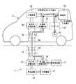
以下、図面を参照して本発明の一実施形態による移動車両及び非接触電力伝送装置について詳細に説明する。図1は、本発明の一実施形態による移動車両及び非接触電力伝送装置の電力系統を示すブロック図である。尚、以下では、移動車両が動力発生源としてモータのみを用いる電気自動車である場合を例に挙げて説明する。 Hereinafter, a mobile vehicle and a non-contact power transmission device according to an embodiment of the present invention will be described in detail with reference to the drawings. FIG. 1 is a block diagram showing a power system of a mobile vehicle and a non-contact power transmission device according to an embodiment of the present invention. In the following, a case where the moving vehicle is an electric vehicle using only a motor as a power generation source will be described as an example.
図1に示す通り、本実施形態の非接触電力伝送装置1は、地表面に設置されており、地上を走行する移動車両としての電気自動車2が、予め定められた位置関係(後述する電磁気結合回路が形成される位置関係)で停車しているときに、電気自動車2に対して電力(蓄電池33を充電するための電力)を非接触で伝送可能である。この非接触電力伝送装置1は、外部電源11、整流回路12、地上側給電回路13、地上側受電回路14、地上側スイッチ15、地上側コイル16及び負荷装置17等を備える。 As shown in FIG. 1, the non-contact
外部電源11は、電気自動車2に伝送すべき電力を生成するために必要となる電力を供給する電源であり、例えば電圧が200[V]である三相交流電力を供給する電源である。尚、この外部電源11は、三相交流電源に限られることはなく、商用交流電源のような単相交流電力を供給する電源であっても良い。整流回路12は、外部電源11から供給される交流電力を整流して直流電力に変換する回路である。なお、外部電源11として燃料電池や太陽電池など直流電源を利用することも可能であり、この場合、整流回路12を省略して、上記直流電源と地上側給電回路13とを直接接続するようにしてもよい。 The
地上側給電回路13は、整流回路12から供給される直流電力を交流電力に変換し、地上側スイッチ15によって地上側コイル16と接続されている場合に、上記交流電力を地上側コイル16に供給することで地上側コイル16と後述する電気自動車2に設けられる車両側コイル34とによって形成される電磁気結合回路を介して非接触で電気自動車2に電力を供給する。 The ground-side
地上側受電回路14は、地上側スイッチ15によって地上側コイル16と接続されている場合に、電気自動車2の車両側コイル34と地上側コイル16とによって形成される電磁気結合回路を介して非接触で供給される電力(交流電力)を受電し、受電した電力を直流電力に変換して負荷装置17に供給する。 When the ground side
地上側スイッチ15は、制御部22(図1では図示省略、図2参照)の制御の下、地上側コイル16の接続先を地上側給電回路13または地上側受電回路14に選択的に切り替える。地上側スイッチ15としては、半導体を利用した電子スイッチや、接点をソレノイドコイルにより物理的に動かして接触・非接触を切り替える機械的なコンタクタが利用可能である。具体的に、地上側スイッチ15は、地上側コイル16に対する電気自動車2の車両側コイル34の位置調整時には、地上側コイル16の接続先を地上側受電回路14に切り替え、一方、位置調整完了後の電気自動車2に対する給電時には、地上側コイル16の接続先を地上側給電回路13に切り替える。 The
地上側コイル16は、地表面に設置され、両端が地上側スイッチ15に接続されている。この地上側コイル16は、外部磁界が作用すると電磁誘導によって起電力を発生し、地上側スイッチ15によって地上側受電回路14に接続されている場合に、地上側スイッチ15を介して地上側受電回路14に上記起電力を出力する。一方、地上側コイル16は、地上側スイッチ15によって地上側給電回路13に接続されている場合に、電気自動車2に設けられた車両側コイル34と近接した状態に配置されることで、地上側給電回路13から地上側スイッチ15を介して供給された交流電力に基づいて電気自動車2の車両側コイル34に非接触給電を行う。 The
つまり、地上側コイル16と電気自動車2に設けられた車両側コイル34とによって電磁気結合回路が形成される。この電磁気結合回路は、地上側コイル16と車両側コイル34とが電磁気的に結合して地上側コイル16から車両側コイル34へ、または車両側コイル34から地上側コイル16への非接触の給電が行われる回路を意味し、「電磁誘導方式」で給電を行う回路と、「電磁界共鳴方式」で給電を行う回路との何れの回路であっても良い。
負荷装置17は、地上側受電回路14に接続されている。このような負荷装置17は、例えば所定の抵抗値を有する抵抗器であり、地上側受電回路14から供給される直流電力を消費する。That is, an electromagnetic coupling circuit is formed by the
The
図1に示す通り、移動車両としての電気自動車2は、モータ31、インバータ32、蓄電池33、車両側コイル34、車両側スイッチ35、車両側受電回路36、車両側給電回路37及び充電装置38等を備え、上記非接触電力伝送装置1の地上側コイル16に対する車両側コイル34の位置を自動調整する機能を有している。 As shown in FIG. 1, an
モータ31は、電気自動車2を移動させるための動力を発生する動力発生源として電気自動車2に搭載されており、インバータ32の駆動に応じた動力を発生する。このモータ31としては、永久磁石型同期モータ、誘導モータ等のモータを用いることができる。インバータ32は、制御部43(図1では図示省略、図2参照)の制御の下で、蓄電池33から供給される電力を用いてモータ31を駆動する。 The
蓄電池33は、電気自動車2に搭載された再充電が可能な電池(例えば、リチウムイオン電池やニッケル水素電池等の二次電池)であり、モータ31を駆動するための電力を供給する。
車両側コイル34は、電気自動車2の底部に設けられており、両端が車両側スイッチ35に接続されている。この車両側コイル34は、外部磁界が作用すると電磁誘導によって起電力を発生し、車両側スイッチ35によって車両側受電回路36に接続されている場合に、車両側スイッチ35を介して車両側受電回路36に上記起電力を出力する。一方、車両側コイル34は、車両側スイッチ35によって車両側給電回路37に接続されている場合に、車両側給電回路37から車両側スイッチ35を介して交流電力が供給されると、該交流電力に基づいて非接触電力伝送装置1の地上側コイル16に非接触給電を行う。The
The
車両側スイッチ35は、制御部43の制御の下で、車両側コイル34の接続先を車両側受電回路36または車両側給電回路37に選択的に切り替える。車両側スイッチ35としては、半導体を利用した電子スイッチや、接点をソレノイドコイルにより物理的に動かして接触・非接触を切り替える機械的なコンタクタが利用可能である。具体的に、車両側スイッチ35は、地上側コイル16に対する車両側コイル34の位置調整時には、車両側コイル34の接続先を車両側給電回路37に切り替え、一方、位置調整完了後の電気自動車2に対する給電時には、車両側コイル34の接続先を車両側受電回路36に切り替える。 The vehicle-
車両側受電回路36は、車両側スイッチ35によって車両側コイル34と接続されている場合に、非接触電力伝送装置1の地上側コイル16と車両側コイル34とによって形成される電磁気結合回路を介して非接触で供給される電力(交流電力)を受電し、受電した電力を直流電力に変換して充電装置38に供給する。 When the vehicle-side
車両側給電回路37は、蓄電池33から供給される直流電力を交流電力に変換し、車両側スイッチ35によって車両側コイル34と接続されている場合に、上記交流電力を車両側コイル34に供給することで車両側コイル34と非接触電力伝送装置1の地上側コイル16とによって形成される電磁気結合回路を介して非接触で非接触電力伝送装置1に電力を供給する。
充電装置38は、車両側受電回路36から供給される電力(直流電力)を用いて蓄電池33の充電を行う装置である。The vehicle-side
The charging
尚、上述した地上側給電回路13、地上側受電回路14、地上側コイル16、車両側コイル34、車両側受電回路36及び車両側給電回路37の構成と動作については、例えば特開2009−225551号公報(「電力伝送システム」)或いは特開2008−236916号公報(「非接触電力伝送装置」)に開示されている。 Note that the configurations and operations of the above-described ground-side
図2は、本発明の一実施形態における移動車両及び非接触電力伝送装置の制御系統を詳細に示す図である。尚、図2において、図1に示す構成と同じ構成については同一の符号を付している。図2に示す通り、上述した非接触電力伝送装置1の整流回路12は、三相全波整流回路(ブリッジ整流回路)で実現されている。また、非接触電力伝送装置1の地上側給電回路13は、スイッチングレッグL1,L2(直列接続された2つのトランジスタと、これら2つのトランジスタにそれぞれ並列接続されたダイオードとからなる回路)が並列接続された回路(インバータ)で実現されている。尚、トランジスタとしては、IGBT(Insulated Gate Bipolar Transistor)やパワーMOSFET(Metal-Oxide-Semiconductor Field-Effect Transistor)などを使用することができる。 FIG. 2 is a diagram illustrating in detail a control system of the moving vehicle and the non-contact power transmission apparatus according to the embodiment of the present invention. In FIG. 2, the same components as those shown in FIG. As shown in FIG. 2, the
また、地上側給電回路13と地上側スイッチ15との間には2つのコンデンサ16aが設けられている。このコンデンサ16aは、地上側スイッチ15を介して地上側コイル16に接続された場合に、地上側コイル16とともに直列共振回路を形成する。地上側コイル16は、地上側スイッチ15によって地上側給電回路13に接続された場合に、一端が、一方のコンデンサ16aを介して地上側給電回路13のスイッチングレッグL1に接続されており、他端が、他方のコンデンサ16aを介して地上側給電回路13のスイッチングレッグL2に接続されている。 Two
また、地上側受電回路14は、4つのダイオードからなるブリッジ整流回路と、ブリッジ整流回路の出力端に並列接続されたコンデンサとによって実現されている。尚、地上側受電回路14と地上側スイッチ15との間にはコンデンサ16bが並列接続されている。 The ground side
非接触電力伝送装置1は、上記の外部電源11〜負荷装置17に加えて、電圧測定器18、電流測定器19、電力量演算器20(受電量演算部)、無線通信装置21(第2の入力部、第2の出力部)及び制御部22を備える。 In addition to the
上記電圧測定器18及び電流測定器19は、地上側受電回路14と負荷装置17との間に設けられており、負荷装置17の入力電圧V1(t)及び入力電流I1(t)をそれぞれ測定する。
電力量演算器20は、電圧測定器18で測定された入力電圧V1(t)と電流測定器19で測定された入力電流I1(t)とを用いて地上側受電回路14で受電された電力の電力量P1を求める。具体的には、V1(t)とI1(t)を乗じて電力量P1を算出する。尚、地上側受電回路14、地上側スイッチ15及び地上側コイル16の損失が零であれば、地上側受電回路14で受電された電力の電力量P1は、地上側コイル16で受電される電力の電力量(受電量)と等しくなる。The
The electric energy calculator 20 uses the input voltage V1 (t) measured by the
無線通信装置21は、電気自動車2に設けられた無線通信装置42と各種情報の無線通信が可能であり、例えば電力量演算器20で求められた電力量P1を示す情報を無線通信装置42に送信し、電気自動車2の制御器43c(後述)が出力する位置調整完了通知N(後述)を受信する。尚、無線通信装置21は、その設置位置を中心として半径が数メートル程度のエリア内に電気自動車2の無線通信装置42が位置する場合に無線通信装置42との通信が可能である。 The
制御部22は、無線通信装置21と無線通信装置42との通信に応じて地上側給電回路13及び地上側スイッチ15を制御する。すなわち、この制御部22は、無線通信装置21が無線通信装置42から受信する信号に応じて地上側給電回路13を制御することにより地上側給電回路13から地上側コイル16に出力する電力を制御すると共に、地上側スイッチ15を制御することにより地上側コイル16の接続先を地上側給電回路13または地上側受電回路14に切り替える。 The
また、図2に示す通り、電気自動車2の車両側受電回路36は、4つのダイオードからなるブリッジ整流回路と、ブリッジ整流回路の出力端に並列接続されたコンデンサとによって実現されている。尚、車両側受電回路36と車両側スイッチ35との間にはコンデンサ34aが並列接続されており、モータ31にはモータ31の回転角を検出するレゾルバやエンコーダ等の回転角検出器31aが取り付けられている。 As shown in FIG. 2, the vehicle-side
また、車両側給電回路37は、スイッチングレッグL1a,L2a(直列接続された2つのトランジスタと、これら2つのトランジスタにそれぞれ並列接続されたダイオードとからなる回路)が並列接続された回路(インバータ)で実現されている。尚、トランジスタとしては、非接触電力伝送装置1の地上側給電回路13と同様に、IGBTやパワーMOSFETなどを使用することができる。 The vehicle-side
また、車両側給電回路37と車両側スイッチ35との間には2つのコンデンサ34bが設けられている。このコンデンサ34bは、車両側スイッチ35を介して車両側コイル34に接続された場合に、車両側コイル34とともに直列共振回路を形成する。車両側コイル34は、車両側スイッチ35によって車両側給電回路37に接続された場合に、一端が、一方のコンデンサ34bを介して車両側給電回路37のスイッチングレッグL1aに接続されており、他端が、他方のコンデンサ34bを介して地上側給電回路13のスイッチングレッグL2aに接続されている。 In addition, two
電気自動車2は、上記のモータ31〜充電装置38に加えて、電圧測定器39、電流測定器40、電力量演算器41(給電量演算部)、無線通信装置42(入力部、出力部)及び制御部43を備える。 In addition to the
電圧測定器39及び電流測定器40は、車両側給電回路37と蓄電池33との間に設けられており、車両側給電回路37の入力電圧V2(t)及び入力電流I2(t)をそれぞれ測定する。
電力量演算器41は、電圧測定器39で測定された入力電圧V2(t)と電流測定器40で測定された入力電流I2(t)とを用いて車両側給電回路37に供給される電力の電力量P2を求める。具体的には、V2(t)とI2(t)を乗じて電力量P2を算出する。尚、車両側コイル34、車両側スイッチ35及び車両側給電回路37の損失が零であれば、車両側給電回路37に供給される電力の電力量P2は、車両側コイル34から給電される電力の電力量(給電量)と等しくなる。The
The
無線通信装置42は、非接触電力伝送装置1に設けられた無線通信装置21と各種情報の無線通信が可能であり、例えば無線通信装置21から送信されてくる電力量P1を示す情報を受信し、制御器43cが出力する位置調整完了通知N(後述)を送信する。尚、無線通信装置42は、自身を中心として半径が数メートル程度のエリア内に非接触電力伝送装置1の無線通信装置21が位置する場合に無線通信装置21との通信が可能である。 The
制御部43は、図1,図2に示す各ブロックを制御することによって、電気自動車2の動作を制御する。例えば、モータ31に取り付けられた回転角検出器31aの検出結果を常時モニタしつつモータ31を駆動するインバータ32を制御することによって、電気自動車2の走行を制御する。また、制御部43は、非接触電力伝送装置1の地上側コイル16に対する車両側コイル34の位置調整時には、電気自動車2から非接触電力伝送装置1への電力伝送効率ε(後述)を参照しつつ、非接触電力伝送装置1の設置場所又はその近くに停車された電気自動車2をゆっくり移動(走行)させて、電気自動車2の停車位置を調整する。 The
この制御部43は、上述した蓄電池33を充電するときの停車位置を調整するために、効率計算器43a、指令値生成器43b、及び制御器43cを備える。効率計算器43aは、地上側コイル16と車両側コイル34との位置調整時において、電力量演算器41で求められた電力量P2と無線通信装置42で受信された電力量P1を示す情報とに基づいて、電気自動車2から非接触電力伝送装置1への電力伝送効率εを算出する。具体的には、電力量P1を電力量P2で除算することによって電力伝送効率εを算出する。 The
指令値生成器43bは、効率計算器43aで算出された電力伝送効率εに応じて、モータ31の回転角指令値を生成する。制御器43cは、指令値生成器43bで生成された回転角指令値に基づいて、回転角検出器31aの検出結果をモニタしつつ、インバータ32に対してトルク指令値を出力する。また、制御器43cは、図示しない操作装置から運転者の操作によって充電指示が入力された場合には、車両側スイッチ35を制御して車両側スイッチ35の接続先を車両側給電回路37に切り替える。さらに、制御器43cは、効率計算器43aで算出された電力伝送効率εが上昇から一定あるいは下降に転じるタイミングで車両側スイッチ35を制御して車両側スイッチ35の接続先を車両側受電回路36に切り替えると共に位置調整完了通知Nを無線通信装置42に出力する。 The command value generator 43b generates a rotation angle command value for the
ここで、モータ31は、減速比が既知の減速機(図示省略)を介して半径が既知のタイヤを回転させるため、モータ31の回転角と電気自動車2の移動量は一定の関係にある。具体的には、タイヤの半径をr、減速機の減速比をnとすると、モータが1回転したときに電気自動車2は距離(2πr/n)だけ移動する。このため、モータ31の回転角を制御することにより、電気自動車2の移動量を制御することができる。 Here, since the
次に、上記構成における非接触電力伝送装置1及び電気自動車2の動作について説明する。図3は、本発明の一実施形態による移動車両及び非接触電力伝送装置の動作を示すフローチャートである。 Next, the operation of the non-contact
まず、運転者が電気自動車2を運転して、電気自動車2を非接触電力伝送装置1の設置場所又はその近くに移動させて停車させた後に、電気自動車2の図示しない操作装置に対して充電指示を行う。すると、電気自動車2の制御器43cは、充電装置38を制御して動作を停止させ(ステップS11)、車両側スイッチ35を制御して車両側コイル34の接続先を車両側給電回路37に切り替え(ステップS12)、電力伝送効率εを測定するために車両側給電回路37を動作させて微小電力の伝送を開始させる(ステップS13)。尚、電気自動車2が非接触電力伝送装置1の給電可能エリア内にいる場合には、非接触電力伝送装置1の地上側コイル16と電気自動車2の車両側コイル34とによって電磁気結合回路が形成される。 First, the driver drives the
一方、非接触電力伝送装置1の制御部22は、電気自動車2が非接触電力伝送装置1の給電可能エリア内にいるか否かを判断する。例えば、制御部22は、無線通信装置21が、電気自動車2の無線通信装置42と無線通信が可能であるか否かによって、電気自動車2が非接触電力伝送装置1の給電可能エリア内にいるか否かを判断する。
制御部22は、電気自動車2が非接触電力伝送装置1の給電可能エリア内にいると判断した場合、地上側スイッチ15を制御して地上側コイル16の接続先を地上側受電回路14に切り替える(ステップS31)。これによって、図4に示すように、地上側コイル16が電気自動車2から受電した電力は、地上側スイッチ15及び地上側受電回路14を介して負荷装置17に供給される。On the other hand, the
When the
これに対し、電気自動車2の制御器43cは、微小電力の伝送を開始すると、インバータ32を制御して電気自動車2の前進を開始させる(ステップS14)。このとき、インバータ32は、蓄電池33から供給される電力に基づいてモータ31を駆動する。 On the other hand, the
制御器43cは、電気自動車2の前進を開始させると、電気自動車2の前進によって効率計算器43aで算出される電力伝送効率εが上昇したか否かを判断する(ステップS15)。制御器43cは、電力伝送効率εが上昇したと判断した場合(ステップS15の判断結果が「YES」の場合)には、インバータ32を制御して電気自動車2のゆっくりとした前進を継続させる(ステップS16)。そして、制御器43cは、電気自動車2の前進によって効率計算器43aで算出される電力伝送効率εが上昇したか否かを再び判断する(ステップS17)。 When starting the forward movement of the
制御器43cは、電力伝送効率εが上昇したと判断した場合(ステップS17の判断結果が「YES」の場合)には、インバータ32を制御して電気自動車2のゆっくりとした前進を継続させる(ステップS16)。これに対し、制御器43cは、電力伝送効率εが上昇しないと判断した場合(ステップS17の判断結果が「NO」の場合)には、インバータ32を制御して電気自動車2を停止させる(ステップS18)。すなわち、制御器43cは、電気自動車2が前進している時に、電力伝送効率εが上昇から一定あるいは下降に転じた場合には、電気自動車2を停止させる。 When the
他方、制御器43cは、電気自動車2の前進を開始させた直後に、電気自動車2の前進によって効率計算器43aで算出される電力伝送効率εが上昇しないと判断した場合(ステップS15の判断結果が「NO」の場合)には、インバータ32を制御して電気自動車2の後進を開始させる(ステップS19)。そして、制御器43cは、電気自動車2のゆっくりとした後進を継続させ(ステップS20)、後進によって効率計算器43aで算出される電力伝送効率εが上昇したか否かを判断する(ステップS21)。 On the other hand, when the
制御器43cは、電力伝送効率εが上昇したと判断した場合(ステップS21の判断結果が「YES」の場合)には、インバータ32を制御して電気自動車2のゆっくりとした後進を継続させる(ステップS20)。これに対し、制御器43cは、電力伝送効率εが上昇しないと判断した場合(ステップS21の判断結果が「NO」の場合)には、インバータ32を制御して電気自動車2を停止させる(ステップS22)。すなわち、制御器43cは、電気自動車2が後進している時に、電力伝送効率εが上昇から一定あるいは下降に転じた場合には、電気自動車2を停止させる。 When the
制御器43cは、ステップS18又はステップS22の処理によって電気自動車2を停止させると、電力伝送効率εを測定するための微小電力の伝送を停止すると共に車両側スイッチ35を制御して車両側コイル34の接続先を車両側受電回路36に切り替え、さらに位置調整が完了して電気自動車2が停止しかつ微小電力の伝送を停止したことを通知する位置調整完了通知Nを無線通信装置42に送信させる(ステップS23)。そして、制御器43cは、ステップS23の後に、充電装置38を制御して充電動作を開始させる一方でインバータ32を制御して動作を停止させる(ステップS24)。 When the
一方、非接触電力伝送装置1の制御部22は、ステップS31の後に、無線通信装置21が上述した位置調整完了通知Nを無線通信装置42から受信すると、地上側スイッチ15を制御して地上側コイル16の接続先を地上側給電回路13に切り替え、地上側給電回路13を制御して地上側コイル16から充電用の電力(蓄電池33を充電する大電力)の伝送を開始させる(ステップS32)。つまり、制御部22は、地上側コイル16から充電用の大電力を伝送する。 On the other hand, when the
この結果、電気自動車2では、充電装置38によって蓄電池33の充電が行われる(ステップS25)。具体的に、図5に示すように、非接触電力伝送装置1からの交流電力は、地上側コイル16と車両側コイル34とによって形成される電磁気結合回路を介して電気自動車2に非接触で伝送されて車両側受電回路36で受電される。車両側受電回路36で受電された交流電力は直流電力に変換され、この変換された直流電力が充電装置38に供給される。そして、この直流電流を用いた蓄電池33の充電が充電装置38によって行われる。続いて、制御器43cは、充電装置38による充電によって蓄電池33が満状態になると、充電装置38を停止させて蓄電池33の充電を停止させる(ステップS26)。 As a result, in the
制御部22は、ステップS32で充電用の電力の伝送を開始した後に、電気自動車2に搭載された蓄電池33の充電が完了したか否かを判断する(ステップS33)。例えば、制御部22は、電気自動車2の無線通信装置42から蓄電池33の充電完了を示す信号が送信されてきたか否かを判断する。制御部22は、充電が完了していないと判断した場合(ステップS33の判断結果が「NO」の場合)には、上記ステップS33の判断を繰り返す。これに対し、制御部22は、充電が完了したと判断した場合(ステップS33の判断結果が「YES」の場合)には、地上側給電回路13を停止させて電力伝送を停止させる(ステップS34)。 The
このような本実施形態は、車両側コイル34と地上側コイル16はいずれも受動的な(半導体のような能動的動作を行わない)回路素子であるため、車両側コイル34と地上側コイル16との電磁気的な結合が強ければ、電力伝送の向き(車両側から地上側へ、地上側から車両側へ)によらず非接触電力伝送を効率良く行えることを用いている。すなわち、車両側コイル34の位置を調整するときに、車両側コイル34を送電コイルとして、地上側コイル16を受電コイルとして使用して電気自動車2から非接触電力伝送装置1への非接触電力伝送の電力伝送効率が高くなるように調整することにより、車両側コイル34を受電コイルとして、地上側コイル16を送電コイルとして使用して非接触電力伝送装置1から電気自動車2への非接触電力伝送を行う時の電力伝送効率も高くなることを利用している。 In this embodiment, since the
以上の通り、本実施形態では、電気自動車2から非接触電力伝送装置1への電力伝送効率εを求め、この電力伝送効率εを参照しつつ電気自動車2を前後に移動させることにより、非接触電力伝送装置1の地上側コイル16と電気自動車2の車両側コイル34との位置を調整している。このため、大きさや車両側コイル34の取り付け位置が異なる電気自動車2であっても正確に位置を調整することができ、効率的に電力を伝送することができる。また、地上側コイル16や車両側コイル34を単独で移動させる機構等が不要であるため、大型化及びコスト上昇を招くこともない。 As described above, in the present embodiment, the power transmission efficiency ε from the
また、本実施形態では、車両側コイル34の位置調整時に、車両側コイル34から地上側コイル16に給電された電力を非接触電力伝送装置1に設けられた負荷装置17によって消費する構成となっているので、電気自動車2に負荷装置を設け、地上側コイル16から車両側コイル34に給電された電力を上記負荷装置によって消費する構成になっている場合と比べて、電気自動車2の重量増加による移動性能の低下を防ぐことができる。 In the present embodiment, when the position of the
以上、本発明の一実施形態について説明したが、本発明は上記実施形態に制限されず、本発明の範囲内で自由に変更が可能である。例えば、上記実施形態では、電気自動車2から非接触電力伝送装置1への電力伝送効率εを参照しつつ電気自動車2を前後に移動させて位置調整を行っていたが、電力伝送効率εに代えて電力量P1(非接触電力伝送装置1で受電された電力)を参照しつつ電気自動車2を前後に移動させて位置調整を行っても良い。 As mentioned above, although one Embodiment of this invention was described, this invention is not restrict | limited to the said embodiment, It can change freely within the scope of the present invention. For example, in the above embodiment, the position adjustment is performed by moving the
非接触電力伝送装置1及び地上側コイル16は、厳密に地表面に一致して設置されていなくてもよい。例えば、非接触電力伝送の効率を著しく低下させない範囲で埋め込んで地表面より低く設置してもよいし、電気自動車2の走行に著しく支障しない範囲で突出させて地表面より高く設置してもよい。 The non-contact
また、上述した実施形態では、電気自動車2を前後に移動させて位置調整を行う場合を例に挙げて説明したが、左右方向に直線的に移動可能な移動車両であれば、左右方向に移動させて位置調整を行うことができる。ここで、移動車両は、ステアリングを操作しなければ前後にのみ移動可能であり、左右方向に直線的に移動することはできないものが殆どである。このため、左右方向の位置ずれが生じても伝送効率の大幅な低下を招くことのない地上側コイルを用いるのが望ましい。 In the above-described embodiment, the case where the position adjustment is performed by moving the
図6は、本発明の一実施形態による非接触電力伝送装置に用いて好適な地上側コイルの設置例を示す図である。図6に示す通り、非接触電力伝送装置1の地上側コイル16は、平面視形状が長方形状のコイルであって、例えば駐車場において、その長手方向が区画線Wに直交し、車止めSTから1メートル程度離間するように区画線Wの間に設置される。このように設置された地上側コイル16の電力伝送可能エリアは、区画線Wに直交する方向に長いため、区画線Wの間における電気自動車2の左右方向の多少のずれが生じたとしても伝送効率の大幅な低下を招くことはない。 FIG. 6 is a diagram illustrating an installation example of a ground-side coil suitable for use in the non-contact power transmission apparatus according to an embodiment of the present invention. As shown in FIG. 6, the
また、上記実施形態では、位置調整を行う際に電気自動車2を連続的に前進或いは後進させていたが、連続移動ではなく微小距離の間欠移動であってもよい。尚、電力伝送効率εが上昇しているか下降しているかは、間欠移動を行う前の電力伝送効率εと1回の間欠動作を行った後の電力伝送効率εとを比較して判断すれば良い。 In the above-described embodiment, the
また、上記実施形態では、図3中のステップS31において、電気自動車2が給電可能エリア内にいるか否かを、非接触電力伝送装置1の無線通信装置21と電気自動車2の無線通信装置42とが無線通信が可能であるか否かによって判断していた。しかしながら、GPS(Global Positioning System:全地球測位システム)等によって得られる電気自動車2の位置に基づいて、電気自動車2が給電可能エリア内にいるか否かを判断するようにしても良い。 Moreover, in the said embodiment, in step S31 in FIG. 3, whether the
尚、電気自動車2の移動方向が一方向に制限される場所(例えば、前進のみに制限される場所)に非接触電力伝送装置1が設置されている場合には、電気自動車2が給電可能エリアに進入した直後に電気自動車2を停車させれば良い。つまり、車両側コイル34が給電可能エリアの外縁の近くに配置されるように電気自動車2を停車させれば良い。
これにより、電気自動車2を前進させれば電力伝送効率εが上昇して図3中のステップS15の判断結果が常に「YES」になるため、電気自動車2が後進するのを防止することができる。In addition, when the non-contact
Thereby, if the
また、位置調整を行っている最中に電力伝送効率εが著しく低下した場合には、電気自動車2の制御器43cは、電気自動車2を停止させる制御を行うとともに電力の伝送を停止させ、無線通信装置42を介して電力伝送効率εが著しく低下した旨を非接触電力伝送装置1に通知するのが望ましい。これにより、位置調整を行っている最中に生ずる想定外の異常を防止することができる。 In addition, when the power transmission efficiency ε significantly decreases during the position adjustment, the
また、電気自動車2の制御器43cは、上記ステップS14〜22において、電気自動車2の位置を変えても、電力伝送効率ε(電力量P1)の値が小さいままであれば、充電開始不可能と判断して、非接触電力伝送装置1へ通知する。その場合、電気自動車2及び非接触電力伝送装置1いずれも動作停止するようにする。 Further, the
また、上記実施形態では、給電対象が蓄電池を搭載した電気自動車である場合を例に挙げて説明したが、本発明はプラグイン・ハイブリッド自動車に適用することもでき、搬送車にも適用することができる。更には、無人式移動車両にも適用することができる。 In the above-described embodiment, the case where the power supply target is an electric vehicle equipped with a storage battery has been described as an example. However, the present invention can also be applied to a plug-in hybrid vehicle and can also be applied to a transport vehicle. Can do. Furthermore, the present invention can be applied to an unmanned mobile vehicle.
また、上記実施形態では、抵抗器を負荷装置17として用いたが、微小電力(数W程度)を消費できる負荷装置17であれば、電子負荷装置を用いてもよい。例えば、微小電力の一部をコンバータで電圧変換し、非接触電力伝送装置1内部の各種機器の制御電源の補助として使用してもよい。 Moreover, in the said embodiment, although the resistor was used as the
また、上記実施形態では、電気自動車2から非接触電力伝送装置1に位置調整完了通知Nを送信し、非接触電力伝送装置1は、位置調整完了通知Nを受信すると、受電から給電に切り替えるが、本発明はこれに限定されない。例えば、電気自動車2が位置調整完了通知Nを送信しない場合でも、非接触電力伝送装置1において、制御部22は、電力量P1に基づいて位置調整の完了を判断して、受電から給電に切り替えるようにしてもよい。 Moreover, in the said embodiment, the position adjustment completion notification N is transmitted from the
1 非接触電力伝送装置
2 電気自動車(移動車両)
11 外部電源
12 整流回路
13 地上側給電回路
14 地上側受電回路
15 地上側スイッチ
16 地上側コイル
17 負荷装置
16a コンデンサ
16b コンデンサ
18 電圧測定器
19 電流測定器
20 電力量演算器(受電量演算部)
21 無線通信装置(第2の入力部、第2の出力部)
22 制御部
31 モータ
32 インバータ
33 蓄電池
34 車両側コイル
35 車両側スイッチ
36 車両側受電回路
37 車両側給電回路
38 充電装置
34a コンデンサ
34b コンデンサ
39 電圧測定器
40 電流測定器
41 電力量演算器(給電量演算部)
42 無線通信装置(入力部、出力部)
43 制御部
31a 回転角検出器1 Non-contact
DESCRIPTION OF
21 wireless communication device (second input unit, second output unit)
DESCRIPTION OF
42 Wireless communication device (input unit, output unit)
43
Claims (7)
Translated fromJapanese外部から給電される電力の受電あるいは前記蓄電池から供給された電力の外部の所定の抵抗値を有する負荷装置への給電を非接触で行う車両側コイルと、
前記車両側コイルが給電した電力の受電量が外部から入力される入力部と、
前記受電量を参照しつつ、前記モータを制御して前記車両側コイルの外部に対する位置を調整する制御部と
を備えることを特徴とする移動車両。In a mobile vehicle comprising a motor that generates power for movement and a storage battery that supplies electric power for driving the motor,
A vehicle-side coil for supplying power from the power receiver, or the storage battery being externallyet feeding electricity tothe load device having an external predetermined resistance value of the power suppliedin a non-contact,
An input unit from which an amount of power received by the vehicle-side coil is input from the outside;
A moving vehicle comprising: a control unit that adjusts a position of the vehicle side coil with respect to the outside by controlling the motor while referring to the amount of power received.
前記制御部は、前記受電量と前記給電量とに基づいて前記車両側コイルから外部への電力伝送効率を求め、前記受電量に代えて前記電力伝送効率を参照しつつ前記モータを制御することを特徴とする請求項1に記載の移動車両。A power supply amount calculation unit for obtaining a power supply amount of power supplied to the outside by the vehicle side coil;
The control unit obtains power transmission efficiency from the vehicle-side coil to the outside based on the power reception amount and the power supply amount, and controls the motor while referring to the power transmission efficiency instead of the power reception amount. The mobile vehicle according to claim 1.
位置調整完了通知を外部に出力すると、前記車両側コイルによる電力の受電を開始することを特徴とする請求項1から請求項3の何れか一項に記載の移動車両。An output unit that outputs a position adjustment completion notification indicating that the position adjustment of the vehicle-side coil has been completed;
The mobile vehicle according to any one of claims 1 to 3, wherein when the position adjustment completion notification is output to the outside, power reception by the vehicle-side coil is started.
前記地上側コイルが前記車両側コイルから受電した電力を消費する前記負荷装置と、
前記地上側コイルが前記車両側コイルから受電した電力の受電量を求める受電量演算部と、
前記受電量演算部で求められた前記受電量を外部に出力する第2の出力部とを備え、
前記車両側コイルの外部に対する位置調整が完了すると、前記地上側コイルから前記車両側コイルへの給電を開始することを特徴とする非接触電力伝送装置。A non-contact power transmission device that receives or feeds power in a non-contact manner using a ground-side coil with the moving vehicle according to any one of claims 1 to 4,
Andsaid load device that consumes power which the ground side coil is receiving power from the vehicle-side coil,
A power reception amount calculation unit for obtaining a power reception amount of power received by the ground side coil from the vehicle side coil;
A second output unit that outputs the received power amount obtained by the received power amount calculation unit to the outside;
When the position adjustment with respect to the outside of the vehicle side coil is completed, power supply from the ground side coil to the vehicle side coil is started.
前記地上側コイルが前記車両側コイルから受電した電力を消費する前記負荷装置と、
前記地上側コイルが前記車両側コイルから受電した電力の受電量を求める受電量演算部と、
前記受電量演算部で求められた前記受電量を外部に出力する第2の出力部と、
前記位置調整完了通知が入力される第2の入力部とを備え、
前記第2の入力部に前記位置調整完了通知が入力されると、前記地上側コイルから前記車両側コイルへの給電を開始することを特徴とする非接触電力伝送装置。A non-contact power transmission device that receives or feeds power in a non-contact manner using a ground-side coil with the mobile vehicle according to claim 5,
Andsaid load device that consumes power which the ground side coil is receiving power from the vehicle-side coil,
A power reception amount calculation unit for obtaining a power reception amount of power received by the ground side coil from the vehicle side coil;
A second output unit for outputting the received power amount obtained by the received power amount calculation unit to the outside;
A second input unit to which the position adjustment completion notification is input,
When the position adjustment completion notification is input to the second input unit, the contactless power transmission device starts feeding power from the ground side coil to the vehicle side coil.
Priority Applications (5)
| Application Number | Priority Date | Filing Date | Title |
|---|---|---|---|
| JP2012131786AJP6044124B2 (en) | 2012-06-11 | 2012-06-11 | Mobile vehicle and non-contact power transmission device |
| EP12851490.8AEP2783900B1 (en) | 2011-11-25 | 2012-11-21 | Mobile vehicle and non-contact power transmission device |
| PCT/JP2012/080122WO2013077340A1 (en) | 2011-11-25 | 2012-11-21 | Mobile vehicle and non-contact power transmission device |
| CN201280057363.8ACN103946058B (en) | 2011-11-25 | 2012-11-21 | Mobile vehicle and non-contact power transmission device |
| US14/284,661US9132739B2 (en) | 2011-11-25 | 2014-05-22 | Vehicle and wireless power transmission device |
Applications Claiming Priority (1)
| Application Number | Priority Date | Filing Date | Title |
|---|---|---|---|
| JP2012131786AJP6044124B2 (en) | 2012-06-11 | 2012-06-11 | Mobile vehicle and non-contact power transmission device |
Publications (2)
| Publication Number | Publication Date |
|---|---|
| JP2013258800A JP2013258800A (en) | 2013-12-26 |
| JP6044124B2true JP6044124B2 (en) | 2016-12-14 |
Family
ID=49954762
Family Applications (1)
| Application Number | Title | Priority Date | Filing Date |
|---|---|---|---|
| JP2012131786AExpired - Fee RelatedJP6044124B2 (en) | 2011-11-25 | 2012-06-11 | Mobile vehicle and non-contact power transmission device |
Country Status (1)
| Country | Link |
|---|---|
| JP (1) | JP6044124B2 (en) |
Families Citing this family (4)
| Publication number | Priority date | Publication date | Assignee | Title |
|---|---|---|---|---|
| JP2016073018A (en)* | 2014-09-26 | 2016-05-09 | トヨタ自動車株式会社 | Power transmission equipment |
| CN110073572A (en)* | 2016-09-16 | 2019-07-30 | Tdk电子股份有限公司 | Wireless power transmitter, Wireless power transmission system and the method for driving Wireless power transmission system |
| DE112020005826T5 (en)* | 2020-02-13 | 2022-09-08 | Ihi Corporation | Power supply device and power supply system |
| JP7746737B2 (en)* | 2021-02-25 | 2025-10-01 | セイコーエプソン株式会社 | Rectifier circuit and power receiving control device |
Family Cites Families (4)
| Publication number | Priority date | Publication date | Assignee | Title |
|---|---|---|---|---|
| JP2008289273A (en)* | 2007-05-17 | 2008-11-27 | Toyota Motor Corp | Power feeding system and vehicle |
| JP5481091B2 (en)* | 2009-04-14 | 2014-04-23 | 富士通テン株式会社 | Wireless power transmission apparatus and wireless power transmission method |
| JP4905571B2 (en)* | 2010-03-10 | 2012-03-28 | トヨタ自動車株式会社 | Vehicle parking assistance device and vehicle equipped with the same |
| WO2011132272A1 (en)* | 2010-04-21 | 2011-10-27 | トヨタ自動車株式会社 | Vehicle parking assistance device and electric vehicle equipped with same |
- 2012
- 2012-06-11JPJP2012131786Apatent/JP6044124B2/ennot_activeExpired - Fee Related
Also Published As
| Publication number | Publication date |
|---|---|
| JP2013258800A (en) | 2013-12-26 |
Similar Documents
| Publication | Publication Date | Title |
|---|---|---|
| US9132739B2 (en) | Vehicle and wireless power transmission device | |
| JP6427873B2 (en) | Parking assistance device and system | |
| JP5966407B2 (en) | Mobile vehicle and non-contact power transmission device | |
| KR101495470B1 (en) | Torque control apparatus and contactless charging system | |
| US20210143684A1 (en) | Contactless power feeding apparatus and contactless power feeding system | |
| US9073442B2 (en) | Inductively charged vehicle with automatic positioning | |
| JP5509883B2 (en) | Wireless charging device for vehicle | |
| JP6090333B2 (en) | Non-contact power supply device, non-contact power supply system, and non-contact power supply method | |
| EP3103673B1 (en) | Parking assistance device and parking assistance method | |
| JP5719466B2 (en) | Contactless charging system | |
| EP4124493B1 (en) | Charging apparatus and new energy vehicle | |
| KR101922781B1 (en) | Charging device and contactless power supply device | |
| JP5966332B2 (en) | Mobile vehicle and non-contact power transmission device | |
| JP6044124B2 (en) | Mobile vehicle and non-contact power transmission device | |
| JP2013169109A (en) | Mobile vehicle and non contact power transmission apparatus | |
| JP2011250498A (en) | Non-contact power feeding device | |
| JP5974460B2 (en) | Mobile vehicle and non-contact power transmission device | |
| JP5930182B2 (en) | antenna | |
| JP2012239360A (en) | Contactless feed system | |
| JP6354565B2 (en) | Power receiving device | |
| JP6860430B2 (en) | Contactless power transfer system |
Legal Events
| Date | Code | Title | Description |
|---|---|---|---|
| A621 | Written request for application examination | Free format text:JAPANESE INTERMEDIATE CODE: A621 Effective date:20150423 | |
| A131 | Notification of reasons for refusal | Free format text:JAPANESE INTERMEDIATE CODE: A131 Effective date:20160329 | |
| A521 | Request for written amendment filed | Free format text:JAPANESE INTERMEDIATE CODE: A523 Effective date:20160509 | |
| A521 | Request for written amendment filed | Free format text:JAPANESE INTERMEDIATE CODE: A821 Effective date:20160510 | |
| TRDD | Decision of grant or rejection written | ||
| A01 | Written decision to grant a patent or to grant a registration (utility model) | Free format text:JAPANESE INTERMEDIATE CODE: A01 Effective date:20161018 | |
| A61 | First payment of annual fees (during grant procedure) | Free format text:JAPANESE INTERMEDIATE CODE: A61 Effective date:20161031 | |
| R151 | Written notification of patent or utility model registration | Ref document number:6044124 Country of ref document:JP Free format text:JAPANESE INTERMEDIATE CODE: R151 | |
| R250 | Receipt of annual fees | Free format text:JAPANESE INTERMEDIATE CODE: R250 | |
| LAPS | Cancellation because of no payment of annual fees |