JP6042243B2 - Monitoring system, monitoring server, and monitoring method - Google Patents
Monitoring system, monitoring server, and monitoring methodDownload PDFInfo
- Publication number
- JP6042243B2 JP6042243B2JP2013054599AJP2013054599AJP6042243B2JP 6042243 B2JP6042243 B2JP 6042243B2JP 2013054599 AJP2013054599 AJP 2013054599AJP 2013054599 AJP2013054599 AJP 2013054599AJP 6042243 B2JP6042243 B2JP 6042243B2
- Authority
- JP
- Japan
- Prior art keywords
- monitoring
- monitoring device
- request message
- control instruction
- server
- Prior art date
- Legal status (The legal status is an assumption and is not a legal conclusion. Google has not performed a legal analysis and makes no representation as to the accuracy of the status listed.)
- Active
Links
Images


Landscapes
- Data Exchanges In Wide-Area Networks (AREA)
- Mobile Radio Communication Systems (AREA)
Description
Translated fromJapanese本発明は、装置を遠隔監視する監視システムに関し、特に、アドレスが動的に変更する装置の監視する技術に関する。 The present invention relates to a monitoring system for remotely monitoring a device, and more particularly to a technique for monitoring a device whose address dynamically changes.
遠隔地に点在する装置(例えば、移動体通信システムの無線基地局装置)の動作を遠隔監視するための技術として、特開2007−150892号公報がある。特開2007−150892号公報には、無線基地局に電源が投入されると、DHCPサーバによりリース期間が無期限のIPアドレス等が設定され、以降、該無線基地局は、上記IPアドレスにより管理される技術が開示されている。 Japanese Unexamined Patent Application Publication No. 2007-150892 is a technique for remotely monitoring the operation of a device (for example, a radio base station device of a mobile communication system) scattered in a remote place. In Japanese Patent Application Laid-Open No. 2007-150892, when a wireless base station is turned on, an IP address or the like whose lease period is indefinite is set by a DHCP server, and thereafter, the wireless base station is managed by the IP address. Disclosed techniques are disclosed.
前述した、無線基地局の監視方法では、リース期間が無期限のIPアドレスが無線基地局に設定される。よって、管理サーバは、無線基地局毎に設定されたアドレスを用いて、無線基地局にアクセスすることができる。 In the wireless base station monitoring method described above, an IP address with an indefinite lease period is set in the wireless base station. Therefore, the management server can access the radio base station using the address set for each radio base station.
しかし、無線基地局に設定されるアドレスが動的に変化するシステムでは、管理サーバは、無線基地局に現在設定されているアドレスが分からないので、無線基地局にアクセスすることができない。このため、管理サーバは、無線基地局からの報告を受信することはできても、無線基地局へ指令を送信することができなかった。 However, in a system in which the address set in the radio base station changes dynamically, the management server cannot access the radio base station because the address currently set in the radio base station is unknown. For this reason, even if the management server can receive a report from the radio base station, it cannot send a command to the radio base station.
また、監視対象装置は様々な種類があり、各種の監視対象装置が出力するデータは様々な形式があり、その処理が困難であった。 Moreover, there are various types of monitoring target devices, and the data output by various monitoring target devices has various formats, which makes it difficult to process.
本願発明は、監視対象装置に設定されるアドレスが動的に変更する場合でも、装置を監視し、装置に指示をすることができ、さらに、複数種類の監視対象装置から出力される異なる形式のデータを処理することができるシステムの提供を目的とする。 The present invention can monitor the device even when the address set in the monitoring target device is dynamically changed, can instruct the device, and can output different types of output from a plurality of types of monitoring target devices. The object is to provide a system capable of processing data.
本願において開示される発明の代表的な一例を示せば以下の通りである。すなわち、監視対象の状態を監視する監視装置及び前記監視装置からデータを収集する監視サーバを備える監視システムであって、前記監視装置は、前記監視対象の状態を示すデータを含むリクエストメッセージを、前記監視サーバに対して定期的に送信し、前記監視サーバは、前記監視装置に送信すべき制御指示を一時的に格納するキューバッファを有し、オペレータからの入力を前記監視サーバに送信する端末に接続されており、前記端末から制御指示を受信すると、前記制御指示による制御の対象となる監視装置の識別情報を抽出し、抽出された識別情報及び受信した制御指示を前記キューバッファに格納し、前記監視装置から送信されたリクエストメッセージから、前記監視装置のアドレスを特定し、前記リクエストメッセージを送信した前記監視装置に送信すべき制御指示が前記キューバッファに格納されている場合、前記制御指示及び当該制御指示による制御の対象となる監視装置の識別情報を前記キューバッファから読み出し、前記読み出した制御指示が正しいかを判定し、所定のフォーマットに従って制御指示及び引数の値を設定して当該制御指示を含むメッセージを作成し、前記作成されたメッセージを、前記監視装置から送信されたリクエストメッセージの応答として、当該監視装置に送信する。A typical example of the invention disclosed in the present application is as follows. That is, a monitoring system including a monitoring device that monitors a state of a monitoring target and a monitoring server that collects data from the monitoring device, wherein the monitoring device sends a request message including data indicating the state of the monitoring target, The monitoring server periodically transmits to the monitoring server, the monitoring server has aqueue buffer for temporarily storing a control instruction to be transmitted to the monitoring device,and a terminal that transmits an input from an operator to the monitoring server When connected and receiving a control instruction from the terminal, it extracts the identification information of the monitoring device to be controlled by the control instruction, stores the extracted identification information and the received control instruction in the queue buffer, The address of the monitoring device is specified from the request message transmitted from the monitoring device, and the request message is transmitted. If the control instruction to said to be transmitted to the monitoring device is stored in thequeue buffer,it reads the identification information of the control instruction and is subject to control by this control instruction monitoring device from the queue buffer, the read control It is determined whether the instruction is correct, a control instruction and an argument value are set according to a predetermined format , a message including the control instruction is generated, and the generated message is transmitted as a response to the request message transmitted from the monitoring device To the monitoring device.
本発明の代表的な実施の形態によれば、監視装置に設定されるアドレスが動的に変更される場合でも、監視装置と通信することができる。また、異なる形式の出力データを処理することができる。 According to the exemplary embodiment of the present invention, communication with a monitoring device can be performed even when an address set in the monitoring device is dynamically changed. Also, different types of output data can be processed.
図1は、本発明の実施形態の監視システムの構成を示すブロック図である。 FIG. 1 is a block diagram showing a configuration of a monitoring system according to an embodiment of the present invention.
本実施形態の監視システムは、監視サーバ100、クライアント端末200及び監視装置300を有する。 The monitoring system of this embodiment includes a
監視サーバ100、クライアント端末200及び監視装置300は、ネットワーク400によって接続される。なお、監視サーバ100及びクライアント端末200を接続するネットワークと、クライアント端末200及び監視装置300を接続するネットワークとは、一つのネットワークでも、別個のネットワークでもよい。 The
監視サーバ100は、プロセッサ(CPU)101、メモリ102、記憶装置(HDD)103及び通信インターフェース(I/F)104を有する計算機である。監視サーバ100は、論理的又は物理的に構成された単一又は複数の計算機上で稼働するシステムである。システムは、同一の計算機上の複数のスレッドによって動作してもよく、複数の物理的計算機資源上に構築された仮想計算機上で動作してもよい。 The
プロセッサ101は、メモリ102に格納されたプログラムを実行する演算装置である。 The
メモリ102は、不揮発性の記憶素子であるROM及び揮発性の記憶素子であるRAMを含む。ROMは、不変のプログラム(例えば、BIOS)などを格納する。RAMは、DRAM(Dynamic Random Access Memory)のような高速かつ揮発性の記憶素子で構成され、記憶装置103に格納されたプログラム及びプログラムの実行時に使用されるデータを一時的に格納する。The
記憶装置103は、例えば、磁気記憶装置、フラッシュメモリ等の大容量かつ不揮発性の記憶装置であり、プロセッサ101が実行するプログラム及びプログラムの実行時に使用されるデータを格納する。すなわち、プログラムは、記憶装置103から読み出されて、RAMにロードされて、プロセッサ101によって実行される。 The
通信インターフェース104は、所定のプロトコルに従って、他の装置との通信を制御するネットワークインターフェース装置である。 The
プロセッサ101によって実行されるプログラムは、リムーバブルメディア(CD−ROM、フラッシュメモリなど)又はネットワークを介して監視サーバ100に提供され、非一時的記憶媒体である補助記憶装置103に格納される。このため、監視サーバ100は、リムーバブルメディアを読み込むインターフェースを備えるとよい。 A program executed by the
クライアント端末200は、プログラムを実行するプロセッサ、前記プロセッサで実行されるプログラムを格納するメモリ、通信インターフェース及びユーザインターフェース(例えば、表示画面、入力装置)を有する計算機である。クライアント端末200は、例えば、ブラウザが動作しており、監視サーバ100から出力された情報をオペレータに表示し、オペレータの入力を受け付け、監視サーバ100に送信する。なお、クライアント端末200で動作するプログラムは、専用のアプリケーションプログラムでもよい。 The
監視装置300は、プログラムを実行するプロセッサ、前記プロセッサで実行されるプログラムを格納するメモリ、通信インターフェース及び監視用インターフェース(例えば、USBインターフェース)を有する装置である。監視装置300の通信インターフェースは、後述するように、TCP/IPプロトコルによって監視サーバ100と通信する。 The
監視装置300は、監視用インターフェースを介して、基地局500(電池ユニット510)と接続されており、電池ユニット510の状態の情報を取得し、電池ユニット510に充電、放電などを指示する。 The
監視装置300には、監視装置300を一意に識別するためのデバイスIDが付与されている。デバイスIDは、監視装置300が送信するリクエスト電文や、クライアント端末200が送信する制御コマンドに含まれる。 The
また、監視装置300には、ネットワーク400を介して通信するためのアドレスが付与される。なお、本実施形態の監視システムにおいては、監視装置300に付与されるアドレスは動的に変更される。図示は省略するが、ネットワーク400には、監視装置300にアドレスを付与する装置(例えば、IPアドレスを付与するDHCPサーバ)が接続されている。 The
基地局500は、本実施形態の監視システムによる監視対象であり、エリア内の移動局と無線によって通信する。基地局500は、停電時に電源を供給する電池ユニット510を有する。電池ユニット510は、電池セル及び制御部を有する。制御部は、電池の出力電圧、充放電電流、充電量などの電池セルの情報を収集する。制御部は監視装置300と接続されており、監視装置300は制御部が収集した電池セルの情報を取得する。 The
図2は、本発明の実施形態の監視サーバ100の構成を示す機能ブロック図である。 FIG. 2 is a functional block diagram illustrating the configuration of the
監視サーバ100は、接続制御部110、データ送受信部111、データキュー112、データ処理部113、ストレージキュー114、データ格納処理部115、インターフェース(API)116、データベース117、電文フォーマット情報118、データグラムプラグイン120、認証部121及び認証情報122を有する。 The
接続制御部110、データ送受信部111、データ処理部113、データ格納処理部115、インターフェース(API)116、データグラムプラグイン120及び認証部121は、監視サーバ100のプロセッサ101が所定のプログラムを実行することによって実装される。データキュー112及びストレージキュー114は、メモリ102に設けられる。データベース117及び認証情報122は、記憶装置103又は外部の記憶装置に格納される。 The
接続制御部110は、監視装置300との接続(例えば、コネクションの設定、解放など)を制御する。 The
データ送受信部111は、監視装置300から送信されたリクエスト電文を受信し、受信したリクエスト電文をデータキュー112に格納する。また、データ送受信部111は、データ処理部113が生成したレスポンス電文を監視装置300へ送信する。 The data transmitter /
データキュー112は、データ送受信部111とデータ処理部113との間に設けられ、監視装置300から受信したリクエスト電文を格納するバッファメモリである。 The
データ処理部113は、監視装置300から受信したリクエスト電文を処理し、ストレージキュー114に格納する。また、データ処理部113は、クライアント端末200から受信した制御コマンドを処理する。 The
ストレージキュー114は、データ処理部113とデータ格納処理部115との間に設けられ、認証された監視装置300から受信したリクエスト電文及びクライアント端末200から受信した制御コマンドを格納するバッファメモリである。 The
データ格納処理部115は、データベース117にデータを書き込み、データベース117からデータを読み出す。 The data
インターフェース(API)116は、クライアント端末200に対するインターフェースであり、クライアント端末200に表示すべき画面データを生成し、クライアント端末200からの入力を受ける。 The interface (API) 116 is an interface to the
データベース117は、監視装置300から受信したリクエスト電文及び当該リクエスト電文を分解したデータを格納する。なお、データベース117は、リクエスト電文そのものを格納しなくてもよい。また、データベース117は、リクエスト電文及びレスポンス電文の形式の情報を格納する。 The
電文フォーマット情報118は、監視サーバ100が扱うリクエスト電文及びレスポンス電文の形式の情報を格納するデータベースである。 The
データグラムプラグイン120は、監視装置300の種類、すなわち、監視装置300が送信するリクエスト電文の形式(すなわち、監視装置が行う業務の種類)に対応して設けられるプログラムモジュールである。 The datagram plug-in 120 is a program module provided corresponding to the type of the
認証部121は、監視装置300のデバイスIDを用いて、監視装置300を認証する。認証情報122は、監視サーバ100がデータを収集する監視装置300のデバイスIDが記録されている。 The
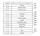
図3Aは、本発明の実施形態の監視システムにおいて送信されるリクエスト電文の形式の一例を説明する図である。 FIG. 3A is a diagram illustrating an example of a format of a request message transmitted in the monitoring system according to the embodiment of this invention.
図3Aに示すリクエスト電文は、監視装置300から監視サーバ100へ送信される電文で、スタートタグ3001から開始し、メッセージ長3002、コマンドコード3003と続き、ボディに、監視サーバ100が収集するデータ3005〜3009及び時刻3010を含み、CRC3011、エンドタグ3012で終了する。 The request message shown in FIG. 3A is a message transmitted from the
リクエスト電文は、監視装置300を特定するための情報として、デバイスID3004を含む。なお、リクエスト電文は、監視装置300の属性情報(デバイス名、シリアル番号、バージョンなど)を含んでもよい。 The request message includes a
また、リクエスト電文は、監視サーバ100が収集する電池ユニット510の状態として、出力電圧3005、充電量3006、充放電電流3007、温度3008、状態コード3009などを含む。 The request message includes an
図3Bは、本発明の実施形態の監視システムにおいて送信されるレスポンス電文の形式の一例を説明する図である。 FIG. 3B is a diagram illustrating an example of a response message format transmitted in the monitoring system according to the embodiment of this invention.
図3Bに示すレスポンス電文は、監視サーバ100から監視装置300へ送信される電文で、スタートタグ3101から開始し、メッセージ長3102、コマンドコード3103と続き、ボディに、コマンド3104及びコマンドパラメータ3105を含み、CRC3106、エンドタグ3107で終了する。 The response message shown in FIG. 3B is a message transmitted from the
レスポンス電文は、監視サーバ100を特定するための情報として、ステーションID3106を含む。なお、レスポンス電文は、時刻を含んでもよい。 The response message includes a
図4は、本発明の実施形態の電文のやり取りを示すシーケンス図である。 FIG. 4 is a sequence diagram illustrating exchange of electronic messages according to the embodiment of this invention.
監視装置300は、基地局500の電池ユニット510の状態(出力電圧、充放電電流、充電量など)の電池セルの情報を収集し、繰り返し(例えば、所定の時間間隔で)、監視サーバ100にリクエスト電文2001、2002、2003を送信する。監視装置300が送信するリクエスト電文には、送信元の監視装置300のデバイスIDが含まれている。 The
監視サーバ100と監視装置300との間の通信には、例えば、HTTPプロトコルを用いることができる。すなわち、監視装置300から監視サーバ100へ送信されるリクエスト電文はHTTPリクエストであり、監視サーバ100から監視装置300へ送信されるレスポンス電文はHTTPレスポンスである。 For example, an HTTP protocol can be used for communication between the monitoring
また、クライアント端末200は、ユーザから入力されたデータ要求コマンド2011を監視サーバ100に送信する。 In addition, the
監視サーバ100は、クライアント端末200からデータ要求コマンド2011を受信すると、受信したデータ要求コマンドによって指定される条件に従ってデータベース117を検索し、条件に合致するデータを取得し、データベース117から取得した監視データを表示する画面を生成し、クライアント端末200に送信する。 When the
このようにして、監視サーバ100が監視装置300から収集した監視データを、クライアント端末200が閲覧することができる。 In this way, the
また、クライアント端末200は、オペレータから入力された制御コマンド2013を監視サーバ100に送信する。制御コマンドの引数には、指令の対象となる監視装置300のデバイスIDが含まれている。制御コマンドは、例えば、電池ユニット510に充電を指示したり、放電を指示するものがある。 In addition, the
監視サーバ100は、クライアント端末200から制御コマンド2013を受信すると、制御コマンド2013の引数である制御の対象となる監視装置300のデバイスIDを抽出し、抽出されたデバイスIDと共に、受信した制御コマンドをストレージキュー114に格納する。 When the
そして、監視サーバ100は、監視装置300から受信したリクエスト電文からデバイスIDを抽出し、ストレージキュー114に格納された制御コマンドの引数のデバイスIDと比較する。その結果、受信したリクエスト電文の送信元の監視装置300のデバイスIDと同じデバイスIDの制御コマンドがストレージキュー114に格納されていれば、当該コマンドからレスポンス電文2015を生成し、生成したレスポンス電文2015を、受信したリクエスト電文2003のレスポンスとして、監視装置300に送信する。 Then, the
このようにして、クライアント端末200に入力された制御コマンドが、監視装置300が送信したリクエストのレスポンスとして、監視装置300に送信される。このため、監視装置300のアドレスが動的に変化しても、指令の対象となる監視装置300に制御コマンドを送信することができる。 In this way, the control command input to the
次に、監視装置300からリクエスト電文が入力された場合の処理について説明する。 Next, processing when a request message is input from the
図5は、本発明の実施形態のリクエスト電文を解析する処理のフローチャートである。 FIG. 5 is a flowchart of processing for analyzing a request message according to the embodiment of this invention.
まず、データ送受信部111は、監視装置300からリクエスト電文を受信し、リクエスト電文を受信したポートのIDから当該リクエスト電文の業務IDを特定する(1001)。リクエスト電文の受信ポートと業務IDとの関係は、データ送受信部111のプログラム中(例えば、ヘッダーファイルやコンフィグレーションファイル)に埋め込まれてもよいし、受信ポートと業務IDとを対応付けた情報を別に有してもよい。 First, the data transmission /
データ送受信部111は、特定された業務IDを付して受信したリクエスト電文をデータキュー112に格納する(1002)。 The data transmitting / receiving
その後、データ処理部113は、監視装置300から受信したリクエスト電文及び業務IDをデータキュー112から読み出し、読み出したリクエスト電文の業務IDを用いて対応するデータグラムプラグイン120を特定し、データキュー112から取り出したリクエスト電文をデータグラムプラグイン120に送る(1003)。 Thereafter, the
業務IDに対応するデータグラムプラグイン120を特定するための情報は、データ処理部113のプログラム中(例えば、ヘッダーファイルや設定ファイル)に埋め込まれてもよいし、業務IDとデータグラムプラグイン120を呼び出すための情報(例えば、ポインタ、プログラム名)を対応付けたテーブルに含まれてもよい。 Information for specifying the datagram plug-in 120 corresponding to the business ID may be embedded in the program of the data processing unit 113 (for example, a header file or a setting file). May be included in a table in which information (for example, a pointer and a program name) for calling is associated.
データグラムプラグイン120は、データベース117に格納された電文フォーマットの情報を参照して、監視装置300から受信したリクエスト電文をチェックする(1004)。具体的には、受信したリクエスト電文の長さ、開始コード及び末端コードが正しいかを確認し、受信したリクエスト電文の形式が正しいかを判定する。 The datagram plug-in 120 checks the request message received from the
次に、データグラムプラグイン120は、受信したリクエスト電文からコマンドコードを抽出し、抽出したコマンドコードによって、受信したリクエスト電文の種別を判定する(1005)。例えば、コマンドコードが「0x31 0x31」であれば、受信した電文が監視装置300がデータを送信するためのリクエスト電文であることが分かる。 Next, the datagram plug-in 120 extracts a command code from the received request message, and determines the type of the received request message based on the extracted command code (1005). For example, if the command code is “0x31 0x31”, it can be seen that the received message is a request message for the
その後、データグラムプラグイン120は、リクエスト電文を分解するために必要なメモリの領域を確保し(1006)、電文フォーマット情報118に従って、受信したリクエスト電文をデータ項目毎に分解する(1007)。分解前のリクエスト電文は、監視装置300の種類毎に所定の電文フォーマットに従ったバイト位置にデータが格納されたものである。リクエスト電文は、分解されると、固定長データで構成される所定のデータ構造体定義に従ったデータ列に変換される。 Thereafter, the datagram plug-in 120 secures a memory area necessary for decomposing the request message (1006), and decomposes the received request message for each data item according to the message format information 118 (1007). The request message before disassembly has data stored at byte positions according to a predetermined message format for each type of
そして、データグラムプラグイン120は、リクエスト電文から抽出したデバイスIDを、認証部121に送る。 Then, the datagram plug-in 120 sends the device ID extracted from the request message to the
認証部121は、デバイスIDを用いて監視装置300を認証する(1008)。具体的には、認証情報122を参照し、認証すべき監視装置300のデバイスIDが認証情報122に格納されている場合、監視装置300の認証が成功する。認証部121は、認証時に、監視装置300が関係する業務を識別してもよい。The
監視装置300の認証に成功すると、データ処理部113は、リクエスト電文を分解したデータをデータグラムプラグイン120から受け取り、ストレージキュー114に格納する(1009)。 When the authentication of the
データ格納処理部115は、リクエスト電文を分解したデータをストレージキュー114から取り出し、データベース117に書き込む(1010)。 The data
次に、クライアント端末200に入力されたコマンドの処理について説明する。 Next, processing of commands input to the
図6は、本発明の実施形態のレスポンス電文を生成する処理のフローチャートである。 FIG. 6 is a flowchart of processing for generating a response message according to the embodiment of this invention.
クライアント端末200は、オペレータから入力された制御コマンドを送信する。クライアント端末200が送信する制御コマンドの引数には、指令の対象となる監視装置300のデバイスIDが含まれている。 The
API116は、クライアント端末200から制御コマンドを受信し(1101)、受信した制御コマンドを引数(デバイスID)と共に、ストレージキュー114に格納する(1102)。 The
監視装置300の認証が成功すると、データ処理部113は、認証された監視装置300のデバイスIDを用いてストレージキュー114を参照し、当該監視装置300に送信すべきレスポンス電文が格納されているかを判定する(1103)。 If the authentication of the
その結果、認証された監視装置300に送信すべきコマンドがストレージキュー114に格納されていれば、データ処理部113は、ストレージキュー114から制御コマンド及び当該制御コマンドの引数のデバイスIDを読み出す(1104)。 As a result, if the command to be transmitted to the authenticated
そして、データ処理部113は、電文フォーマット情報118から、監視装置300から送信されたリクエスト電文に付された業務IDに対応する電文フォーマットを取得する(1105)。 Then, the
データ処理部113は、受信した制御コマンドの長さをチェックする(1106)。 The
その後、データ処理部113は、レスポンス電文を生成するために必要なメモリの領域を確保し(1107)、送信するコマンドが正しいかを判定し(1108)、電文フォーマット情報118から取得した電文フォーマットに従って、コマンド及び引数の値を設定し、レスポンス電文を生成する(1109)。 Thereafter, the
なお、ステップ1103で、認証された監視装置300に送信すべきコマンドがストレージキュー114に格納されていないと判定された場合、データ処理部113は、コマンドを含まないレスポンス電文を生成する(1109)。 If it is determined in
データ処理部113は、監視装置300から受信したデータの返信(すなわち、HTTPレスポンス)として、生成したレスポンス電文を監視装置300に送信する(1110)。 The
以上に説明したように、本発明の実施形態では、クライアント端末200に入力されたコマンドが、監視装置300が送信したデータのレスポンスとして、監視装置300に送信される。このため、監視装置300のアドレスが動的に変化しても、指令の対象となる監視装置300にレスポンス電文を送信することができる。 As described above, in the embodiment of the present invention, the command input to the
また、データグラムプラグイン120が、監視装置300が出力するデータの形式に応じた処理を行うので、異なる形式の出力データを処理することができる。 In addition, since the datagram plug-in 120 performs processing according to the format of data output from the
以上、本発明を添付の図面を参照して詳細に説明したが、本発明はこのような具体的構成に限定されるものではなく、添付した請求の範囲の趣旨内における様々な変更及び同等の構成を含むものである。 Although the present invention has been described in detail with reference to the accompanying drawings, the present invention is not limited to such specific configurations, and various modifications and equivalents within the spirit of the appended claims Includes configuration.
100 監視サーバ
113 データ処理部
120 データグラムプラグイン
200 クライアント端末
300 監視装置
400 ネットワーク
500 基地局DESCRIPTION OF
Claims (9)
Translated fromJapanese前記監視装置は、前記監視対象の状態を示すデータを含むリクエストメッセージを、前記監視サーバに対して定期的に送信し、
前記監視サーバは、
前記監視装置に送信すべき制御指示を一時的に格納するキューバッファを有し、
オペレータからの入力を前記監視サーバに送信する端末に接続されており、
前記端末から制御指示を受信すると、前記制御指示による制御の対象となる監視装置の識別情報を抽出し、抽出された識別情報及び受信した制御指示を前記キューバッファに格納し、
前記監視装置から送信されたリクエストメッセージから、前記監視装置のアドレスを特定し、
前記リクエストメッセージを送信した前記監視装置に送信すべき制御指示が前記キューバッファに格納されている場合、前記制御指示及び当該制御指示による制御の対象となる監視装置の識別情報を前記キューバッファから読み出し、前記読み出した制御指示が正しいかを判定し、所定のフォーマットに従って制御指示及び引数の値を設定して当該制御指示を含むメッセージを作成し、
前記作成されたメッセージを、前記監視装置から送信されたリクエストメッセージの応答として、当該監視装置に送信することを特徴とする監視システム。A monitoring system comprising a monitoring device that monitors a state of a monitoring target and a monitoring server that collects data from the monitoring device,
The monitoring device periodically transmits a request message including data indicating the status of the monitoring target to the monitoring server,
The monitoring server is
Aqueue buffer for temporarily storing a control instruction to be transmitted to the monitoring device;
Connected to a terminal that sends input from the operator to the monitoring server;
When receiving a control instruction from the terminal, the identification information of the monitoring device to be controlled by the control instruction is extracted, the extracted identification information and the received control instruction are stored in the queue buffer,
Identify the address of the monitoring device from the request message sent from the monitoring device,
When a control instruction to be transmitted to the monitoring apparatus that has transmitted the request message is stored in thequeue buffer , thecontrol instruction and identification information of a monitoring apparatus to be controlled by the control instruction are read from the queue buffer. , Determine whether the read control instruction is correct, set the control instruction and argument values according to a predetermined format to create a message including the control instruction,
The monitoring system, wherein the created message is transmitted to the monitoring device as a response to the request message transmitted from the monitoring device.
前記監視サーバは、
前記監視装置から受信したリクエストメッセージから、前記監視装置を一意に識別するための識別情報を抽出し、
前記抽出された識別情報を認証し、
前記認証に成功した後、前記監視装置から受信したリクエストメッセージに含まれるデータをデータベースに格納することを特徴とする監視システム。The monitoring system according to claim 1,
The monitoring server is
Extracting identification information for uniquely identifying the monitoring device from the request message received from the monitoring device;
Authenticating the extracted identification information;
A monitoring system, wherein data included in a request message received from the monitoring device is stored in a database after the authentication is successful.
前記監視サーバは、
前記監視装置の種別に応じたプログラムを有し、
前記監視装置から受信したリクエストメッセージから抽出された識別情報によって、前記監視装置の種別に応じたプログラムを特定し、
前記特定されたプログラムが、当該監視装置が送信するリクエストメッセージの形式に従って、前記監視装置から受信したリクエストメッセージを所定の項目毎に分解して、前記データベースに格納されるデータを生成することを特徴とする監視システム。The monitoring system according to claim 2,
The monitoring server is
Having a program according to the type of the monitoring device;
By identifying information extracted from the request message received from the monitoring device, identify a program according to the type of the monitoring device,
The identified program generates the data stored in the database by decomposing the request message received from the monitoring device into predetermined items according to the format of the request message transmitted by the monitoring device. Monitoring system.
前記監視装置は、前記監視対象の状態を示すデータを含むリクエストメッセージを、前記監視サーバに対して定期的に送信し、
前記監視サーバは、
プログラムを実行するプロセッサと、
前記プロセッサで実行されるプログラム及び前記監視装置に送信すべき制御指示を一時的に格納するメモリとを有し、
オペレータからの入力を前記監視サーバに送信する端末に接続されており、
前記端末から制御指示を受信すると、前記制御指示による制御の対象となる監視装置の識別情報を抽出し、抽出された識別情報及び受信した制御指示を前記メモリに格納し、
前記監視装置から送信されたリクエストメッセージから、前記監視装置のアドレスを特定し、
前記リクエストメッセージを送信した前記監視装置に送信すべき制御指示が前記メモリに格納されている場合、前記制御指示及び当該制御指示による制御の対象となる監視装置の識別情報を前記メモリから読み出し、前記読み出した制御指示が正しいかを判定し、所定のフォーマットに従って制御指示及び引数の値を設定して当該制御指示を含むメッセージを作成し、
前記作成されたメッセージを、前記監視装置から送信されたリクエストメッセージの応答として、当該監視装置に送信することを特徴とする監視サーバ。A monitoring server that collects data from a monitoring device that monitors the status of the monitoring target;
The monitoring device periodically transmits a request message including data indicating the status of the monitoring target to the monitoring server,
The monitoring server is
A processor for executing the program;
A program that is executed by the processor and a memory that temporarily stores a control instruction to be transmitted to the monitoring device;
Connected to a terminal that sends input from the operator to the monitoring server;
When receiving a control instruction from the terminal, it extracts the identification information of the monitoring device to be controlled by the control instruction, stores the extracted identification information and the received control instruction in the memory,
Identify the address of the monitoring device from the request message sent from the monitoring device,
When a control instruction to be transmitted to the monitoring apparatus that has transmitted the request message is stored in the memory, thecontrol instruction and identification information of a monitoring apparatus to be controlled by the control instruction are read from the memory, Determine whether the read control instruction is correct, set the control instruction and argument values according to a predetermined format , create a message containing the control instruction,
A monitoring server, wherein the created message is transmitted to the monitoring device as a response to the request message transmitted from the monitoring device.
前記監視装置から受信したリクエストメッセージから、前記監視装置を一意に識別するための識別情報を抽出し、
前記抽出された識別情報を認証し、
前記認証に成功した後、前記監視装置から受信したリクエストメッセージに含まれるデータをデータベースに格納することを特徴とする監視サーバ。The monitoring server according to claim 4,
Extracting identification information for uniquely identifying the monitoring device from the request message received from the monitoring device;
Authenticating the extracted identification information;
A monitoring server that stores data included in a request message received from the monitoring device in a database after the authentication is successful.
前記監視装置の種別に応じたプログラムを有し、
前記監視装置から受信したリクエストメッセージから抽出された識別情報によって、前記監視装置の種別に応じたプログラムを特定し、
前記特定されたプログラムが、当該監視装置が送信するリクエストメッセージの形式に従って、前記監視装置から受信したリクエストメッセージを所定の項目毎に分解して、前記データベースに格納されるデータを生成することを特徴とする監視サーバ。The monitoring server according to claim 5,
Having a program according to the type of the monitoring device;
By identifying information extracted from the request message received from the monitoring device, identify a program according to the type of the monitoring device,
The identified program generates the data stored in the database by decomposing the request message received from the monitoring device into predetermined items according to the format of the request message transmitted by the monitoring device. A monitoring server.
前記監視方法は、対象装置の状態を監視する監視装置及び前記監視装置からデータを収集する監視サーバを備える監視システムにおいて実行され、
前記監視サーバは、オペレータからの入力を前記監視サーバに送信する端末に接続されており、
前記監視方法は、
前記監視装置が、前記監視対象の状態を示すデータを含むリクエストメッセージを、前記監視サーバに対して定期的に送信し、
前記監視サーバが、前記端末から制御指示を受信すると、前記制御指示による制御の対象となる監視装置の識別情報を抽出し、抽出された識別情報及び受信した制御指示をメモリに格納し、
前記監視サーバが、前記監視装置から送信されたリクエストメッセージから、前記監視装置のアドレスを特定し、
前記監視サーバが、前記リクエストメッセージを送信した前記監視装置に送信すべき制御指示が前記メモリに格納されている場合、前記制御指示及び当該制御指示による制御の対象となる監視装置の識別情報を前記メモリから読み出し、前記読み出した制御指示が正しいかを判定し、所定のフォーマットに従って制御指示及び引数の値を設定して当該制御指示を含むメッセージを作成し、
前記監視サーバが、前記作成されたメッセージを、前記監視装置から送信されたリクエストメッセージの応答として、当該監視装置に送信することを特徴とする監視方法。A monitoring method for monitoring the status of a monitoring target,
The monitoring method is executed in a monitoring system including a monitoring device that monitors a state of a target device and a monitoring server that collects data from the monitoring device,
The monitoring server is connected to a terminal that transmits an input from an operator to the monitoring server;
The monitoring method includes:
The monitoringdevice, a request message comprising data indicating the state of the monitored periodically sends to the monitoring server,
When the monitoring server receives a control instruction from the terminal, it extracts the identification information of the monitoring device to be controlled by the control instruction, stores the extracted identification information and the received control instruction in a memory,
The monitoringserver, from been request message transmitted from the monitoring device to identify the address of the monitoring device,
The monitoringserver, if the request message transmitted the monitoring device control instruction to send to the are stored inthe memory,the identification information of the control instruction and subject to monitoring device the control of the control instruction Read from the memory, determine whether the read control instruction is correct, set the control instruction and argument values according to a predetermined format to create a message including the control instruction,
Monitoring method the monitoringserver, the messages created, as a response to the request message sent from the monitoring device, and transmits to the monitoring apparatus.
前記監視サーバは、前記監視装置から受信したリクエストメッセージから、前記監視装置を一意に識別するための識別情報を抽出し、
前記監視サーバは、前記抽出された識別情報を認証し、
前記監視サーバは、前記認証に成功した後、前記監視装置から受信したリクエストメッセージに含まれるデータをデータベースに格納することを特徴とする監視方法。The monitoring method according to claim 7, comprising:
The monitoring server extracts identification information for uniquely identifying the monitoring device from the request message received from the monitoring device,
The monitoring server authenticates the extracted identification information;
The monitoring method, wherein the monitoring server stores data included in a request message received from the monitoring device in a database after the authentication is successful.
前記監視サーバは、前記監視装置の種別に応じたプログラムを有し、
前記監視サーバは、前記監視装置から受信したリクエストメッセージから抽出された識別情報によって、前記監視装置の種別に応じたプログラムを特定し、
前記監視サーバは、前記特定されたプログラムが、当該監視装置が送信するリクエストメッセージの形式に従って、前記監視装置から受信したリクエストメッセージを所定の項目毎に分解して、前記データベースに格納されるデータを生成することを特徴とする監視方法。The monitoring method according to claim 8, comprising:
The monitoring server has a program corresponding to the type of the monitoring device,
The monitoring server specifies a program corresponding to the type of the monitoring device by identification information extracted from the request message received from the monitoring device,
The monitoring server decomposes the request message received from the monitoring device into predetermined items according to the format of the request message transmitted by the monitoring device, and stores the data stored in the database. The monitoring method characterized by producing | generating.
Priority Applications (2)
| Application Number | Priority Date | Filing Date | Title |
|---|---|---|---|
| JP2013054599AJP6042243B2 (en) | 2013-03-18 | 2013-03-18 | Monitoring system, monitoring server, and monitoring method |
| CN201310378593.0ACN104065505A (en) | 2013-03-18 | 2013-08-27 | Monitoring system, monitoring server and monitoring method |
Applications Claiming Priority (1)
| Application Number | Priority Date | Filing Date | Title |
|---|---|---|---|
| JP2013054599AJP6042243B2 (en) | 2013-03-18 | 2013-03-18 | Monitoring system, monitoring server, and monitoring method |
Publications (2)
| Publication Number | Publication Date |
|---|---|
| JP2014183334A JP2014183334A (en) | 2014-09-29 |
| JP6042243B2true JP6042243B2 (en) | 2016-12-14 |
Family
ID=51553047
Family Applications (1)
| Application Number | Title | Priority Date | Filing Date |
|---|---|---|---|
| JP2013054599AActiveJP6042243B2 (en) | 2013-03-18 | 2013-03-18 | Monitoring system, monitoring server, and monitoring method |
Country Status (2)
| Country | Link |
|---|---|
| JP (1) | JP6042243B2 (en) |
| CN (1) | CN104065505A (en) |
Families Citing this family (4)
| Publication number | Priority date | Publication date | Assignee | Title |
|---|---|---|---|---|
| DE102015225617A1 (en)* | 2015-02-06 | 2016-08-11 | Robert Bosch Gmbh | Method for monitoring a drive-by-wire system of a motor vehicle |
| WO2016157477A1 (en)* | 2015-04-01 | 2016-10-06 | 三菱電機株式会社 | Management system |
| WO2017168674A1 (en)* | 2016-03-31 | 2017-10-05 | 東芝三菱電機産業システム株式会社 | Data reproduction device for plant-monitoring control system |
| US11031800B2 (en) | 2016-07-15 | 2021-06-08 | Nec Corporation | Determination apparatus, surveillance apparatus, surveillance system, determination method, surveillance method, and non-transitory storage medium |
Family Cites Families (6)
| Publication number | Priority date | Publication date | Assignee | Title |
|---|---|---|---|---|
| JPH1165968A (en)* | 1997-08-13 | 1999-03-09 | Nippon Telegr & Teleph Corp <Ntt> | Network management method and system |
| TW200408242A (en)* | 2002-09-06 | 2004-05-16 | Matsushita Electric Industrial Co Ltd | Home terminal apparatus and communication system |
| JP2004280717A (en)* | 2003-03-18 | 2004-10-07 | Matsushita Electric Works Ltd | Remote control monitoring system and information communicating method used therefor |
| NO323215B1 (en)* | 2005-02-04 | 2007-01-29 | Tandberg Telecom As | Firewall / NAT Protected Network Monitoring and Configuration Procedure |
| JP5524026B2 (en)* | 2010-11-15 | 2014-06-18 | 株式会社日立製作所 | Element terminal and communication system |
| CN102509886B (en)* | 2011-11-03 | 2013-06-12 | 长沙威佳通信科技有限公司 | System for automatically monitoring state of base station antennae |
- 2013
- 2013-03-18JPJP2013054599Apatent/JP6042243B2/enactiveActive
- 2013-08-27CNCN201310378593.0Apatent/CN104065505A/enactivePending
Also Published As
| Publication number | Publication date |
|---|---|
| CN104065505A (en) | 2014-09-24 |
| JP2014183334A (en) | 2014-09-29 |
Similar Documents
| Publication | Publication Date | Title |
|---|---|---|
| CN104598513B (en) | A kind of method of data flow control and system based on web page frame | |
| CN110737566A (en) | Host performance monitoring method and device, electronic equipment and storage medium | |
| CN107665233A (en) | Database data processing method, device, computer equipment and storage medium | |
| CN110764807A (en) | An upgrade method, system, server and terminal device | |
| WO2015180291A1 (en) | Method and system for monitoring server cluster | |
| CN105739317A (en) | Intelligent household control method, device and system | |
| JP6042243B2 (en) | Monitoring system, monitoring server, and monitoring method | |
| CN110399150B (en) | A bios upgrade method, system, device and computer storage medium | |
| WO2016058368A1 (en) | Home appliance control method and control device, and home data terminal | |
| US10754748B2 (en) | System and method for constructing extensible event log with javascript object notation (JSON) encoded payload data | |
| CN106485261A (en) | A kind of method and apparatus of image recognition | |
| CN108076457A (en) | A kind of safety-type power grid private radio communication module of wisdom based on linux system | |
| US9723480B2 (en) | Information processing device, server device, data communication system, data communication method, and computer-readable storage medium storing data communication program | |
| CN114124916A (en) | Data transmission method and device, electronic equipment and storage medium | |
| US9781010B2 (en) | Managing remote devices | |
| US8813029B2 (en) | Remote card content management using synchronous server-side scripting | |
| CN107682746A (en) | Wake-up method and device | |
| CN113992739B (en) | A local area network OTA firmware upgrade device, method and system | |
| CN112423322A (en) | Model information sending method, device, storage medium and electronic device | |
| JP5132258B2 (en) | Device monitoring apparatus, device monitoring method, and computer program | |
| CN119377043A (en) | Multi-platform data collection method | |
| CN111045720B (en) | Code management method, code management system, server and medium | |
| CN111131373B (en) | Breathing machine data synchronization system, method, device and storage medium | |
| CN111737084A (en) | Information monitoring method and device, intelligent equipment, computer equipment and medium | |
| JP6248521B2 (en) | Vending machine setting system |
Legal Events
| Date | Code | Title | Description |
|---|---|---|---|
| A621 | Written request for application examination | Free format text:JAPANESE INTERMEDIATE CODE: A621 Effective date:20150908 | |
| A977 | Report on retrieval | Free format text:JAPANESE INTERMEDIATE CODE: A971007 Effective date:20160812 | |
| A131 | Notification of reasons for refusal | Free format text:JAPANESE INTERMEDIATE CODE: A131 Effective date:20160830 | |
| A521 | Request for written amendment filed | Free format text:JAPANESE INTERMEDIATE CODE: A523 Effective date:20160916 | |
| TRDD | Decision of grant or rejection written | ||
| A01 | Written decision to grant a patent or to grant a registration (utility model) | Free format text:JAPANESE INTERMEDIATE CODE: A01 Effective date:20161101 | |
| A61 | First payment of annual fees (during grant procedure) | Free format text:JAPANESE INTERMEDIATE CODE: A61 Effective date:20161109 | |
| R150 | Certificate of patent or registration of utility model | Ref document number:6042243 Country of ref document:JP Free format text:JAPANESE INTERMEDIATE CODE: R150 | |
| R250 | Receipt of annual fees | Free format text:JAPANESE INTERMEDIATE CODE: R250 | |
| R250 | Receipt of annual fees | Free format text:JAPANESE INTERMEDIATE CODE: R250 | |
| R250 | Receipt of annual fees | Free format text:JAPANESE INTERMEDIATE CODE: R250 | |
| R250 | Receipt of annual fees | Free format text:JAPANESE INTERMEDIATE CODE: R250 | |
| R250 | Receipt of annual fees | Free format text:JAPANESE INTERMEDIATE CODE: R250 |