JP6040733B2 - Sample dispensing device with detection function - Google Patents
Sample dispensing device with detection functionDownload PDFInfo
- Publication number
- JP6040733B2 JP6040733B2JP2012258396AJP2012258396AJP6040733B2JP 6040733 B2JP6040733 B2JP 6040733B2JP 2012258396 AJP2012258396 AJP 2012258396AJP 2012258396 AJP2012258396 AJP 2012258396AJP 6040733 B2JP6040733 B2JP 6040733B2
- Authority
- JP
- Japan
- Prior art keywords
- nozzle
- sample
- cap
- container
- sample dispensing
- Prior art date
- Legal status (The legal status is an assumption and is not a legal conclusion. Google has not performed a legal analysis and makes no representation as to the accuracy of the status listed.)
- Active
Links
Images


Landscapes
- Automatic Analysis And Handling Materials Therefor (AREA)
Description
Translated fromJapanese本発明は、容器に入った試料の液面検出と当該容器のキャップの有無の検出とを同時に行なえる試料分注装置に関する。 The present invention relates to a sample dispensing apparatus capable of simultaneously detecting the liquid level of a sample contained in a container and detecting the presence or absence of a cap of the container.
採血管やサンプルカップ等の容器に入った、液体試料や組織からの抽出液等に含まれる成分を分析するための、化学分析装置や免疫化学分析装置といった生化学分析装置において、当該試料等を分注する際は、当該試料等の入った容器を、キャップをあらかじめ外した状態で当該装置の試料収納部に載置した後、サンプリングノズルを備えた試料分注装置により前記試料等を吸引して分注する。その際、前記試料等の液面を検知し、その検知結果から、当該ノズルの先端の挿入位置(吸引位置)を制御する技術が一般に用いられている(特許文献1)。 In biochemical analyzers such as chemical analyzers and immunochemical analyzers for analyzing components contained in liquid samples, extracts from tissues, etc. that have entered containers such as blood collection tubes and sample cups, When dispensing, place the container containing the sample in the sample storage part of the device with the cap removed in advance, and then suck the sample or the like with a sample dispensing device equipped with a sampling nozzle. To dispense. At that time, a technique is generally used in which the liquid level of the sample or the like is detected, and the insertion position (suction position) of the tip of the nozzle is controlled based on the detection result (Patent Document 1).
しかしながら、キャップを外すのを忘れた状態で試料等の入った容器を試料収納部に載置すると、サンプリングノズルがキャップに接触し、駆動モータが止まる、ノズルが曲がる、容器を倒す、等の不具合が発生する。 However, if you place the container containing the sample in the sample storage part without forgetting to remove the cap, the sampling nozzle contacts the cap, the drive motor stops, the nozzle bends, the container falls down, etc. Occurs.
前記不具合の発生を防ぐために、レバー付マイクロスイッチを、試料が入った容器(試料収納容器)のキャップの高さに設置することで、当該キャップを検知する装置が考えられる。しかしこのような装置では、特定の長さの試料収納容器と当該容器に対応した外径を有するキャップにしか使えないという制約がある。そのため、複数種類の試料収納容器とキャップに対して前記装置を適用するには、使用する複数種類の試料収納容器とキャップに対応する幅の広いレバーを用いるか、各試料収納容器とキャップに対応する複数のレバー付マイクロスイッチを用いる必要がある。 In order to prevent the occurrence of the inconvenience, an apparatus that detects the cap by placing a micro switch with a lever at the height of the cap of the container (sample storage container) containing the sample can be considered. However, such an apparatus has a restriction that it can be used only for a sample storage container having a specific length and a cap having an outer diameter corresponding to the container. Therefore, in order to apply the device to multiple types of sample storage containers and caps, use a wide lever corresponding to the multiple types of sample storage containers and caps used, or correspond to each sample storage container and cap. It is necessary to use a plurality of micro switches with levers.
またキャップ検知装置の他の例として、サンプリングノズルをバネを介してノズルホルダーに保持し、当該ノズルがサンプル容器の底に衝突したとき、当該ノズルが浮き上がるよう構成したサンプリング手段を備え、当該ノズルが衝突し、ノズルが浮き上がった際、電気流路が切断されることで、キャップを検知する装置が考えられる。しかしながら、当該例も前記例と同様、新たにセンサやスイッチなどの部品を設ける必要がある。 As another example of the cap detection device, the sampling nozzle is held in a nozzle holder via a spring, and when the nozzle collides with the bottom of the sample container, the nozzle is provided with a sampling means configured to float, When a collision occurs and the nozzle is lifted, a device that detects a cap by cutting an electric flow path is conceivable. However, in this example as well, it is necessary to newly provide components such as sensors and switches.
そこで本発明は、センサやスイッチ等の部品を新たに設けることなく、液面への接近または接触を高い信頼性で検知するとともにキャップの有無の検知も可能な、試料分注装置を提供することを目的とする。 Accordingly, the present invention provides a sample dispensing apparatus that can detect the approach or contact to the liquid level with high reliability and can also detect the presence or absence of a cap without newly providing components such as sensors and switches. With the goal.
上記課題を鑑みてなされた本発明は、以下の発明を包含する。 The present invention made in view of the above problems includes the following inventions.
すなわち本発明の第一の態様は、
容器に入った試料を分注可能なサンプリングノズルと、
前記ノズルが前記試料の液面もしくは前記容器のキャップに近接または接触したときの信号を検出する検出器と、
前記検出器で検出した信号の変化から前記試料の液面を検知する液面検知手段と、
前記検出器で検出した信号の変化から前記容器のキャップの有無を検知するキャップ検知手段とを備えた、試料分注装置である。That is, the first aspect of the present invention is:
A sampling nozzle capable of dispensing the sample contained in the container;
A detector for detecting a signal when the nozzle approaches or contacts the liquid level of the sample or the cap of the container;
Liquid level detection means for detecting the liquid level of the sample from a change in the signal detected by the detector;
It is a sample dispensing device provided with a cap detection means for detecting the presence or absence of a cap of the container from a change in the signal detected by the detector.
また本発明の第二の態様は、前記検出器が、発振器と、前記発振器から出力された信号をサンプリングノズルに伝達する手段と、前記ノズルが前記試料の液面もしくは前記容器に近接または接触することで生じるインピーダンス変化を反映する信号を検出する手段とを有した検出器である、前記第一の態様に記載の試料分注装置である。 According to a second aspect of the present invention, the detector includes an oscillator, means for transmitting a signal output from the oscillator to a sampling nozzle, and the nozzle is close to or in contact with the liquid surface of the sample or the container. It is a sample dispensing apparatus as described in said 1st aspect which is a detector which has a means to detect the signal which reflects the impedance change which arises by this.
また本発明の第三の態様は、容器のキャップに接触することでサンプリングノズルに上方の力が加わったとき、前記ノズルを浮き上がった状態で保持するノズル保持手段をさらに備えた、前記第一または第二の態様に記載の試料分注装置である。 The third aspect of the present invention further includes nozzle holding means for holding the nozzle in a lifted state when an upper force is applied to the sampling nozzle by contacting the cap of the container. It is a sample dispensing apparatus as described in a 2nd aspect.
また本発明の第四の態様は、ノズル保持手段が、天面に導電板を有した絶縁性の保護ブロックと、サンプリングノズルと電気的に導通したフランジと、前記導電板と前記フランジとを接触または一定の間隔で離間した状態で保持可能な弾性手段とを有する、前記第三の態様に記載の試料分注装置である。 According to a fourth aspect of the present invention, the nozzle holding means contacts the insulating protective block having a conductive plate on the top surface, the flange electrically connected to the sampling nozzle, and the conductive plate and the flange. Alternatively, the sample dispensing apparatus according to the third aspect, further including an elastic unit that can be held in a state of being separated at a constant interval.
以下、本発明を詳細に説明する。 Hereinafter, the present invention will be described in detail.
本発明の試料分注装置に備える液面検知手段の一例として、静電容量式液面センサがある。前記センサは、導電性を有するサンプリングノズルと発振回路とが電気的に連結されており、前記ノズルが液面に接触した際に得られる、前記ノズルとその周辺との間のインピーダンス変化を反映した電気的信号を検出し、検出した前記信号とあらかじめ得た複数の前記信号との差の変化を感知することで、液面を検知する。サンプリングノズルが発信回路の一部を構成する場合は、前記ノズルとその周辺との間のインピーダンス変化により発振状況が変化するので、発振状況に関係する信号を検出することができる。発振状況に関連する信号としては、発振振幅、発振周波数、位相、消費電力が例示できる。発振回路(発振器)から出力された一定の発振信号をサンプリングノズルに伝達する場合は、前記ノズルとその周辺との間のインピーダンス変化により、前記ノズルとその周辺とから構成される回路の伝達関数が変化するので、伝達関数に関係する信号を取り出すことができる。伝達関数に関連する信号としては、ノズルの交流電位の振幅または位相、発振器からノズルに流れる交流電流の振幅が例示できる。 An example of the liquid level detection means provided in the sample dispensing apparatus of the present invention is a capacitance type liquid level sensor. In the sensor, a conductive sampling nozzle and an oscillation circuit are electrically connected to each other, and reflect a change in impedance between the nozzle and its periphery, which is obtained when the nozzle comes into contact with a liquid surface. The liquid level is detected by detecting an electrical signal and detecting a change in the difference between the detected signal and a plurality of signals obtained in advance. When the sampling nozzle constitutes a part of the transmission circuit, the oscillation state changes due to the impedance change between the nozzle and its periphery, so that a signal related to the oscillation state can be detected. Examples of signals related to the oscillation state include oscillation amplitude, oscillation frequency, phase, and power consumption. When the constant oscillation signal output from the oscillation circuit (oscillator) is transmitted to the sampling nozzle, the transfer function of the circuit composed of the nozzle and the periphery thereof is changed by the impedance change between the nozzle and the periphery thereof. Since it changes, a signal related to the transfer function can be extracted. Examples of the signal related to the transfer function include the amplitude or phase of the alternating potential of the nozzle and the amplitude of the alternating current flowing from the oscillator to the nozzle.
サンプリングノズルが容器のキャップに接触した場合にも、前記ノズルとその周辺との間のインピーダンス変化を反映した信号を検出することができる。そのため、検出した前記信号の変化から前記キャップの有無を検知することができる。サンプリングノズルがキャップに接触したときの前記信号の変化の大きさは、キャップの材質や周囲の環境に依存する。そのため、前記インピーダンス変化を増強する手段を本発明の試料分注装置に備えると、キャップの材質等によらずに、大きな出力信号の変化が得られる点で好ましい。 Even when the sampling nozzle comes into contact with the cap of the container, a signal reflecting the impedance change between the nozzle and its periphery can be detected. Therefore, the presence or absence of the cap can be detected from the detected change in the signal. The magnitude of the change in the signal when the sampling nozzle contacts the cap depends on the material of the cap and the surrounding environment. For this reason, it is preferable to provide the means for enhancing the impedance change in the sample dispensing apparatus of the present invention in that a large change in output signal can be obtained regardless of the material of the cap.
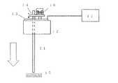
インピーダンス変化を増強する手段の一例として、天面に導電板13を有した絶縁体材料からなるノズル保護ブロック12と、サンプリングノズル11と電気的に導通したフランジ14と、導電板13とフランジ14とを接触または一定の間隔で離間した状態で保持可能な弾性手段(バネ16)とを設けた、ノズル保持手段があげられる(図1)。ノズル11がキャップ15に接触すると、ノズル11がブロック12から浮き上がり(導電板13とフランジ14とが接触している場合は離間、導電板13とフランジ14とが離間している場合はその距離が拡大)、静電容量が小さくなることで、値が変化する。一方、液面と接触すると、ノズル11先端と液体とが導通することで、インピーダンスが変化する。これらの値の変化を反映する出力信号の値と間近で得た同種値との差を感知することで、液面検知およびキャップの有無の検知を行なう。 As an example of means for enhancing the impedance change, a nozzle protection block 12 made of an insulating material having a
インピーダンス変化を増強する手段の別の例として、感圧弾性体からなる板を設け、サンプリングノズルがキャップに接触した時の力により当該感圧弾性体の抵抗値が変化することにより、キャップの有無の検知を行なう態様があげられる。 As another example of means for enhancing the impedance change, a plate made of a pressure-sensitive elastic body is provided, and the resistance value of the pressure-sensitive elastic body changes due to the force when the sampling nozzle comes into contact with the cap. There is a mode in which the detection is performed.
インピーダンス変化を利用した静電容量式液面検知手段と、キャップ検知手段とを組み合わせることで、本発明の試料分注装置が得られることをこれまで説明したが、液面検知手段として静電容量式液面検知手段を用いなくとも、本発明の試料分注装置を得ることができる。 It has been described so far that the sample dispensing device of the present invention can be obtained by combining the capacitance type liquid level detection means using the impedance change and the cap detection means. The sample dispensing apparatus of the present invention can be obtained without using the liquid level detecting means.
例えば、超音波トランスデューサにより、サンプリングノズルに垂直方向または水平方向に超音波振動(パルス)を加え、当該ノズル先端で反射して戻った超音波振動の振幅を検出し、当該ノズルが液体や固体と接触したときの音響インピーダンスの変化を反映する信号を検出する検出器を用いることで、本発明の試料分注装置を得ることができる。音響インピーダンスの変化を反映する信号の例として、振幅や周波数があげられるが、特定の物理量や検出方法に依存されることはない。 For example, an ultrasonic transducer applies ultrasonic vibration (pulse) to the sampling nozzle in the vertical direction or horizontal direction, detects the amplitude of the ultrasonic vibration reflected and returned from the tip of the nozzle, and the nozzle is detected as liquid or solid. The sample dispensing apparatus of the present invention can be obtained by using a detector that detects a signal that reflects a change in acoustic impedance when contacted. An example of a signal that reflects a change in acoustic impedance includes amplitude and frequency, but is not dependent on a specific physical quantity or detection method.
また、サンプリングノズルに圧力センサを設け、シリンジポンプといった体積変化手段により当該ノズルに空気を送り、当該ノズルが液体や固体と接触したときの圧力変化を反映する信号を検出する検出器を用いても、本発明の試料分注装置を得ることができる。なお前記態様において、サンプリングノズルに送る空気の体積をピエゾ素子等により周期的に変化させ、当該ノズルが液体や固体と接触したときの圧力変化の振幅を反映する信号を検出する検出器を用いてもよい。 Alternatively, a sampling sensor may be provided with a pressure sensor, air may be sent to the nozzle by volume changing means such as a syringe pump, and a detector that detects a signal reflecting a pressure change when the nozzle contacts a liquid or solid may be used. The sample dispensing device of the present invention can be obtained. In the above aspect, a detector that periodically changes the volume of air sent to the sampling nozzle by a piezo element or the like and detects a signal reflecting the amplitude of the pressure change when the nozzle comes into contact with a liquid or a solid is used. Also good.
本発明の試料分注装置は、容器に入った試料を分注可能なサンプリングノズルと、前記ノズルが前記試料の液面もしくは前記容器のキャップに近接または接触したときの信号を検出する検出器と、前記検出器で検出した信号の変化から前記試料の液面を検知する液面検知手段と、前記検出器で検出した信号の変化から前記容器のキャップの有無を検知するキャップ検知手段とを備えていることを特徴としており、採血管等の容器に入った試料の液面を高い信頼性をもって検知でき、かつ前記容器のキャップを外すのを忘れた場合でも前記キャップの検知ができるため、サンプリングノズル破損のトラブルを防止することができる。よって本発明の試料分注装置を生化学分析装置に備えることで、大きなコストをかけることなく、生化学分析装置による分析の中断時間を減らすことができる。 The sample dispensing apparatus of the present invention includes a sampling nozzle capable of dispensing a sample contained in a container, a detector for detecting a signal when the nozzle is close to or in contact with the liquid level of the sample or the cap of the container; A liquid level detecting means for detecting the liquid level of the sample from a change in the signal detected by the detector; and a cap detecting means for detecting the presence or absence of a cap of the container from the change in the signal detected by the detector. Sampling is possible because the liquid level of a sample in a container such as a blood collection tube can be detected with high reliability and the cap can be detected even if the cap of the container is forgotten to be removed. The trouble of nozzle breakage can be prevented. Therefore, by providing the sample dispensing apparatus of the present invention in the biochemical analyzer, the interruption time of the analysis by the biochemical analyzer can be reduced without incurring a large cost.
以下、図面を用いて本発明をさらに詳細に説明する。 Hereinafter, the present invention will be described in more detail with reference to the drawings.
本発明の試料分注装置に備えるサンプリングノズルおよびノズル保持手段の具体例を図2に示す。ステンレス鋼製のサンプリングノズル11の上部にはフランジ14がロウ付けされている。樹脂製のノズル保護ブロック12の天面にはノズル11を通すための穴を有した導電板13を設けている。なお、ノズル11と導電板13とは直接接触しないが、フランジ14はバネ16により導電板13に押し付けられ接触している。ノズル11がキャップ15に接触するとノズル11が浮き上がり、フランジ14が導電板13から離間することで、導電板13と導電する部分の面積が小さくなり、導電板13全体の静電容量が小さくなる。 A specific example of the sampling nozzle and nozzle holding means provided in the sample dispensing apparatus of the present invention is shown in FIG. A
図2に示したサンプリングノズルおよびノズル保持手段を備えた本発明の試料分注装置の具体例を図3および4に示す。図3に示す試料分注装置では、ノズル11が発振回路におけるタンク回路の一部を構成しており、インピーダンスが変化すると当該発振回路の発振状況が変化するので、発振振幅や周波数が変化し、発振回路に供給される電源電流が変化する。この変化を直流電圧に変換したものを検出器21で検出する出力信号とすることができるが、電源電流に依存する信号を出力信号としてもよい。 3 and 4 show specific examples of the sample dispensing apparatus of the present invention provided with the sampling nozzle and the nozzle holding means shown in FIG. In the sample dispensing apparatus shown in FIG. 3, the nozzle 11 constitutes a part of the tank circuit in the oscillation circuit, and when the impedance changes, the oscillation state of the oscillation circuit changes, so the oscillation amplitude and frequency change, The power supply current supplied to the oscillation circuit changes. An output signal obtained by converting this change into a DC voltage can be used as an output signal detected by the detector 21, but a signal depending on the power supply current may be used as the output signal.
図4に示す試料分注装置では、一定の周波数で発振する発振回路17とサンプリングノズル11とを抵抗24を介して接続している構成となっている。キャップ15への接触により、ノズル11にかかる信号の振幅が変化するので、当該信号を整流することにより、出力信号を得ることができる。この変化した値とキャップ15への接触直前の同種値との差とを検知することで、キャップを検知する。 The sample dispensing apparatus shown in FIG. 4 has a configuration in which an
図3の試料分注装置において、サンプリングノズル11先端がキャップ15に接触したときの出力信号の変化および値が変化した出力信号(デジタル変換したAD値)と36パルス前の出力信号との差(ΔAD)の変化の一例を図5に示す。なお1パルスの移動距離は約0.0075mmである。 In the sample dispensing apparatus of FIG. 3, the change in the output signal when the tip of the sampling nozzle 11 comes into contact with the cap 15 and the difference between the output signal whose value has changed (digital converted AD value) and the output signal before 36 pulses ( An example of the change in [Delta] AD) is shown in FIG. The moving distance of one pulse is about 0.0075 mm.
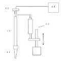
本発明の試料分注装置のさらに別の具体例を図6に示す。図6に示す試料分注装置においてサンプリングノズル11は、その先端にディスポーザブルなサンプリングチップ41を取り付け可能なノズルとなっており、さらにノズル内の圧力を検出するための圧力センサ42を、ノズル11の空気流路に連通する位置に設けている。チップ41をノズル11に装着し、空気を介して容器に入った試料(不図示)をチップ41内に吸引後、別の容器(不図示)に吐出することで試料分注を行なう。チップ41を取り付けたノズル11を下降させながら、シリンジポンプ43を用いて空気を吐出する。チップ41が試料液面またはキャップに接触すると、チップ41内部の圧力が変化する。この変化を検出器44で検出することで、液面検知およびキャップの有無の検知を行なう。 FIG. 6 shows still another specific example of the sample dispensing apparatus of the present invention. In the sample dispensing apparatus shown in FIG. 6, the sampling nozzle 11 is a nozzle to which a disposable sampling chip 41 can be attached at the tip, and a pressure sensor 42 for detecting the pressure in the nozzle is provided. It is provided at a position communicating with the air flow path. The tip 41 is attached to the nozzle 11, and a sample (not shown) contained in the container via air is sucked into the tip 41 and then discharged to another container (not shown) to perform sample dispensing. Air is discharged using the syringe pump 43 while lowering the nozzle 11 to which the tip 41 is attached. When the tip 41 comes into contact with the sample liquid surface or the cap, the pressure inside the tip 41 changes. By detecting this change with the detector 44, the liquid level is detected and the presence or absence of a cap is detected.
本発明の試料分注装置は、生化学分析装置に備える試料分注装置に適用することで、オペレータが間違ってキャップを外し忘れた容器(採血管等)を試料収納部にセットした場合でも、キャップを外し忘れた容器を検知した時には、当該容器からの試料分注は行なわずにスキップをしたり、アラームを出して分注作業を保留状態とすること等により、サンプリングノズルの破損による、検査が長時間中断するリスクを避けることができる。またルーチン検査の長時間の中断を避けなければならない一般の検査室だけでなく、診療所や緊急検査室等、生化学分析装置を使い慣れていないオペレータが操作する用途に対しても好ましい装置といえる。 The sample dispensing device of the present invention is applied to the sample dispensing device provided in the biochemical analyzer, so that even when an operator mistakenly forgets to remove the cap (such as a blood collection tube) is set in the sample storage unit, When a container for which the cap has been forgotten to be removed is detected, the sample nozzle is not dispensed but skipped, or an alarm is issued and the dispensing operation is put on hold. Can avoid the risk of long interruptions. Moreover, it can be said that it is a preferable apparatus not only for general laboratories that must avoid long interruptions of routine examinations but also for applications operated by operators who are not familiar with biochemical analyzers such as clinics and emergency laboratories. .
11:サンプリングノズル
12:ノズル保護ブロック
13:導電板
14:フランジ
15:キャップ
16:バネ
17・26:発振回路
21・44:検出器
22:採血管
23:試料
24:抵抗
27:振幅検知回路
28:液面検知手段
29:キャップ検知手段
41:サンプリングチップ
42:圧力センサ
43:シリンジポンプ11: Sampling nozzle 12: Nozzle protection block 13: Conductive plate 14: Flange 15: Cap 16:
Claims (2)
Translated fromJapanese前記ノズルが前記試料の液面もしくは前記容器のキャップに近接または接触したときの電気的信号を検出する検出器と、
前記検出器で検出した信号の変化から前記試料の液面を検知する静電容量式液面検知手段と、
前記検出器で検出した信号の変化から前記容器のキャップの有無を検知する静電容量式キャップ検知手段と、
前記容器のキャップに接触することでサンプリングノズルに上方の力が加わったとき、前記ノズルを浮き上がった状態で保持するノズル保持手段を備えた、試料分注装置であって、
前記ノズル保持手段が、天面に導電板を有した絶縁性の保護ブロックと、前記サンプリングノズルと電気的に導通したフランジと、前記導電板と前記フランジとを接触または一定の間隔で離間した状態で保持可能な弾性手段とを有する、試料分注装置。A sampling nozzle capable of dispensing the sample contained in the container;
A detector for detecting anelectrical signal when the nozzleapproaches or contacts the liquid level of the sample or the cap of the container;
Capacitance type liquid level detection means for detecting the liquid level of the sample from a change in the signal detected by the detector,
Capacitance type cap detection means for detecting the presence or absence of a cap of the container from a change in the signal detected by the detector;
Asample dispensing apparatuscomprising nozzle holding means forholding the nozzle in a lifted state when an upper force is applied to the sampling nozzle by contacting the cap of the container,
The nozzle holding means is in a state where an insulating protective block having a conductive plate on the top surface, a flange electrically connected to the sampling nozzle, and the conductive plate and the flange are in contact with each other or spaced apart at a constant interval A sample dispensing devicehaving elastic means that can be held by
Priority Applications (1)
| Application Number | Priority Date | Filing Date | Title |
|---|---|---|---|
| JP2012258396AJP6040733B2 (en) | 2012-11-27 | 2012-11-27 | Sample dispensing device with detection function |
Applications Claiming Priority (1)
| Application Number | Priority Date | Filing Date | Title |
|---|---|---|---|
| JP2012258396AJP6040733B2 (en) | 2012-11-27 | 2012-11-27 | Sample dispensing device with detection function |
Publications (2)
| Publication Number | Publication Date |
|---|---|
| JP2014106073A JP2014106073A (en) | 2014-06-09 |
| JP6040733B2true JP6040733B2 (en) | 2016-12-07 |
Family
ID=51027696
Family Applications (1)
| Application Number | Title | Priority Date | Filing Date |
|---|---|---|---|
| JP2012258396AActiveJP6040733B2 (en) | 2012-11-27 | 2012-11-27 | Sample dispensing device with detection function |
Country Status (1)
| Country | Link |
|---|---|
| JP (1) | JP6040733B2 (en) |
Families Citing this family (3)
| Publication number | Priority date | Publication date | Assignee | Title |
|---|---|---|---|---|
| JP6807778B2 (en)* | 2017-03-06 | 2021-01-06 | テラメックス株式会社 | Pipette tip tip detection device, pipette tip tip detection program |
| JP6951854B2 (en)* | 2017-03-29 | 2021-10-20 | 株式会社日立ハイテク | Container transport mechanism and analyzer equipped with this |
| JP7079352B2 (en)* | 2018-07-03 | 2022-06-01 | シーメンス・ヘルスケア・ダイアグノスティックス・インコーポレイテッド | A small piezoelectric air pump that produces pulsatile airflow for proximity sensing of a pipette device |
Family Cites Families (8)
| Publication number | Priority date | Publication date | Assignee | Title |
|---|---|---|---|---|
| JPS61275660A (en)* | 1985-05-31 | 1986-12-05 | Hitachi Ltd | Sampling instrument |
| JP2554202B2 (en)* | 1990-11-28 | 1996-11-13 | 株式会社日立製作所 | Sample dispenser |
| US5493922A (en)* | 1993-07-09 | 1996-02-27 | Akzo N.V. | Liquid level sensing probe and control circuit |
| JP3650823B2 (en)* | 1995-11-10 | 2005-05-25 | 東ソー株式会社 | Liquid level detection device and detection method |
| JPH09325154A (en)* | 1996-06-05 | 1997-12-16 | Eiken Chem Co Ltd | Sample container for examination, sampling nozzle, puncture sampling method and sample supply method |
| JP3672742B2 (en)* | 1998-08-13 | 2005-07-20 | 日本電子株式会社 | Pipette nozzle safety device in analyzer |
| JP5161547B2 (en)* | 2007-11-27 | 2013-03-13 | 株式会社東芝 | Automatic analyzer |
| CN101881706B (en)* | 2010-07-05 | 2014-04-02 | 深圳迈瑞生物医疗电子股份有限公司 | Sampling device and method |
- 2012
- 2012-11-27JPJP2012258396Apatent/JP6040733B2/enactiveActive
Also Published As
| Publication number | Publication date |
|---|---|
| JP2014106073A (en) | 2014-06-09 |
Similar Documents
| Publication | Publication Date | Title |
|---|---|---|
| JP4717312B2 (en) | Fluid transfer probe | |
| EP0633456B1 (en) | Liquid level sensing probe and control circuit | |
| US5855851A (en) | Apparatus for trasferring liquid having liquid level sensing function | |
| CA2501028C (en) | Level sensor apparatus for detecting contact of a pipetting needle with a liquid in a vessel | |
| JP4966913B2 (en) | Liquid dispensing device | |
| US5465629A (en) | Liquid dispensing system with acoustic sensing means | |
| JP4373427B2 (en) | Electrical dripping monitoring | |
| US20150268230A1 (en) | Analyzer, and method of detection liquid level in an analyzer | |
| JP2005345466A5 (en) | ||
| CN101952693A (en) | Method for checking the state of a pipette, pipetting method, pipetting device, and suction tube for a pipetting device | |
| JP6040733B2 (en) | Sample dispensing device with detection function | |
| JP2010522870A (en) | Method and apparatus for detecting contact between pipette needle and liquid in container | |
| JP5830395B2 (en) | Liquid dispensing device | |
| JP3907819B2 (en) | Liquid level detector | |
| US20040185569A1 (en) | Controlling microdrop dispensing apparatus | |
| WO2009079108A1 (en) | Filter and solid phase extraction plate clogged well detection | |
| JP2013044692A (en) | Dispensation mechanism and automatic analyzer using the same | |
| JPH06241862A (en) | Liquid level detecting apparatus | |
| JP3664456B2 (en) | Analyzer with liquid level detection function | |
| JPH05232125A (en) | Sample-sucking detecting method | |
| AU2005211572B2 (en) | Fluid dispense and fluid surface verification system and method | |
| JPH11271319A (en) | Automatic analyzer with liquid level detection function | |
| JP2021143839A (en) | Liquid level detecting device and automatic analyzing device | |
| KR20120110388A (en) | Automatic liquid dispenser and liquid dispensing method | |
| HK1120861A (en) | Electrical drop surveillance |
Legal Events
| Date | Code | Title | Description |
|---|---|---|---|
| A621 | Written request for application examination | Free format text:JAPANESE INTERMEDIATE CODE: A621 Effective date:20151026 | |
| A977 | Report on retrieval | Free format text:JAPANESE INTERMEDIATE CODE: A971007 Effective date:20160720 | |
| A131 | Notification of reasons for refusal | Free format text:JAPANESE INTERMEDIATE CODE: A131 Effective date:20160802 | |
| A521 | Written amendment | Free format text:JAPANESE INTERMEDIATE CODE: A523 Effective date:20160913 | |
| TRDD | Decision of grant or rejection written | ||
| A01 | Written decision to grant a patent or to grant a registration (utility model) | Free format text:JAPANESE INTERMEDIATE CODE: A01 Effective date:20161011 | |
| A61 | First payment of annual fees (during grant procedure) | Free format text:JAPANESE INTERMEDIATE CODE: A61 Effective date:20161024 | |
| R151 | Written notification of patent or utility model registration | Ref document number:6040733 Country of ref document:JP Free format text:JAPANESE INTERMEDIATE CODE: R151 |