JP6040564B2 - Image processing apparatus, projection control method, and program - Google Patents
Image processing apparatus, projection control method, and programDownload PDFInfo
- Publication number
- JP6040564B2 JP6040564B2JP2012106724AJP2012106724AJP6040564B2JP 6040564 B2JP6040564 B2JP 6040564B2JP 2012106724 AJP2012106724 AJP 2012106724AJP 2012106724 AJP2012106724 AJP 2012106724AJP 6040564 B2JP6040564 B2JP 6040564B2
- Authority
- JP
- Japan
- Prior art keywords
- projection
- virtual object
- image
- unit
- control unit
- Prior art date
- Legal status (The legal status is an assumption and is not a legal conclusion. Google has not performed a legal analysis and makes no representation as to the accuracy of the status listed.)
- Expired - Fee Related
Links
Images


Classifications
- G—PHYSICS
- G06—COMPUTING OR CALCULATING; COUNTING
- G06T—IMAGE DATA PROCESSING OR GENERATION, IN GENERAL
- G06T19/00—Manipulating 3D models or images for computer graphics
- G06T19/006—Mixed reality
- G—PHYSICS
- G09—EDUCATION; CRYPTOGRAPHY; DISPLAY; ADVERTISING; SEALS
- G09G—ARRANGEMENTS OR CIRCUITS FOR CONTROL OF INDICATING DEVICES USING STATIC MEANS TO PRESENT VARIABLE INFORMATION
- G09G3/00—Control arrangements or circuits, of interest only in connection with visual indicators other than cathode-ray tubes
- G09G3/001—Control arrangements or circuits, of interest only in connection with visual indicators other than cathode-ray tubes using specific devices not provided for in groups G09G3/02 - G09G3/36, e.g. using an intermediate record carrier such as a film slide; Projection systems; Display of non-alphanumerical information, solely or in combination with alphanumerical information, e.g. digital display on projected diapositive as background
- G09G3/002—Control arrangements or circuits, of interest only in connection with visual indicators other than cathode-ray tubes using specific devices not provided for in groups G09G3/02 - G09G3/36, e.g. using an intermediate record carrier such as a film slide; Projection systems; Display of non-alphanumerical information, solely or in combination with alphanumerical information, e.g. digital display on projected diapositive as background to project the image of a two-dimensional display, such as an array of light emitting or modulating elements or a CRT
- G—PHYSICS
- G09—EDUCATION; CRYPTOGRAPHY; DISPLAY; ADVERTISING; SEALS
- G09G—ARRANGEMENTS OR CIRCUITS FOR CONTROL OF INDICATING DEVICES USING STATIC MEANS TO PRESENT VARIABLE INFORMATION
- G09G2360/00—Aspects of the architecture of display systems
- G09G2360/04—Display device controller operating with a plurality of display units
Landscapes
- Engineering & Computer Science (AREA)
- Physics & Mathematics (AREA)
- Computer Hardware Design (AREA)
- General Physics & Mathematics (AREA)
- Theoretical Computer Science (AREA)
- Computer Graphics (AREA)
- General Engineering & Computer Science (AREA)
- Software Systems (AREA)
- Controls And Circuits For Display Device (AREA)
- User Interface Of Digital Computer (AREA)
- Processing Or Creating Images (AREA)
- Image Processing (AREA)
Description
Translated fromJapanese本開示は、画像処理装置、投影制御方法及びプログラムに関する。 The present disclosure relates to an image processing apparatus, a projection control method, and a program.
近年、実空間に付加的な情報を重畳してユーザに呈示する拡張現実(AR:Augmented Reality)と呼ばれる技術が注目されている。AR技術においてユーザに呈示される情報は、テキスト、アイコン又はアニメーションなどの様々な形態の仮想オブジェクトを用いて可視化される。そして、仮想オブジェクトは、関連付けられる実物体の位置に応じて、AR空間内に配置される。仮想オブジェクトは、一般的には、携帯端末のディスプレイ、ヘッドマウントディスプレイ又は眼鏡型ディスプレイなどの画面上に表示される。しかし、これらディスプレイは、通常、単一のユーザが画像を見ることを前提として設計される。そのため、ユーザにどのようなARコンテンツが提供されているかを第三者が知ることは難しい。 In recent years, a technique called augmented reality (AR) that superimposes additional information on a real space and presents it to a user has attracted attention. Information presented to the user in AR technology is visualized using various forms of virtual objects such as text, icons or animations. The virtual object is arranged in the AR space according to the position of the associated real object. The virtual object is generally displayed on a screen such as a display of a portable terminal, a head mounted display, or a glasses-type display. However, these displays are usually designed on the assumption that a single user views an image. Therefore, it is difficult for a third party to know what AR content is provided to the user.
ところで、実空間に画像を投影可能な投影装置(いわゆるプロジェクタ)を有する端末もまた開発されている(例えば、下記特許文献1参照)。ARコンテンツが投影装置を用いて投影されれば、どのようなARコンテンツが提供されているかを第三者が知ることができる。 By the way, a terminal having a projection device (so-called projector) capable of projecting an image in real space has also been developed (for example, see Patent Document 1 below). If AR content is projected using a projection device, a third party can know what AR content is provided.
しかしながら、ARコンテンツを実空間内の何らかの投影面に単純に投影するだけでは、投影される仮想オブジェクトは、当該仮想オブジェクトと関連付けられる実物体とは直接的に関係のない投影面に映るだけとなる。この場合、“拡張現実感”、即ち現実世界が拡張されたかのような感覚は、第三者には与えられない。従って、ディスプレイ出力用のARコンテンツと同じARコンテンツを単純に投影するのではなく、拡張現実の特性を踏まえてARコンテンツの投影を制御することのできる仕組みが提供されることが望ましい。 However, simply projecting the AR content onto some projection plane in the real space only causes the projected virtual object to be projected on a projection plane that is not directly related to the real object associated with the virtual object. . In this case, “augmented reality”, that is, a feeling as if the real world was expanded, is not given to a third party. Therefore, it is desirable to provide a mechanism that can control the projection of AR content based on the characteristics of augmented reality, rather than simply projecting the same AR content as the AR content for display output.
本開示によれば、撮像装置を用いて実空間を撮像することにより生成される入力画像を取得する画像取得部と、前記入力画像に映る実物体を認識する認識部と、前記認識部により認識される実物体の位置に従って、当該実物体と関連付けられる拡張現実のための仮想オブジェクトの表示位置を決定するオブジェクト制御部と、前記仮想オブジェクトを重畳するための出力画像を投影装置へ出力し、前記表示位置に対応する3次元位置へ前記出力画像を投影させる表示制御部と、を備える画像処理装置が提供される。 According to the present disclosure, an image acquisition unit that acquires an input image generated by imaging a real space using an imaging device, a recognition unit that recognizes a real object that appears in the input image, and a recognition that is performed by the recognition unit An object control unit that determines a display position of a virtual object for augmented reality associated with the real object according to the position of the real object, and an output image for superimposing the virtual object is output to the projection device, An image processing apparatus is provided that includes a display control unit that projects the output image onto a three-dimensional position corresponding to the display position.
また、本開示によれば、撮像装置を用いて実空間を撮像することにより生成される入力画像を取得することと、前記入力画像に映る実物体を認識することと、認識される実物体の位置に従って、当該実物体と関連付けられる拡張現実のための仮想オブジェクトの表示位置を決定することと、前記仮想オブジェクトを重畳するための出力画像を投影装置へ出力し、前記表示位置に対応する3次元位置へ前記出力画像を投影させることと、を含む投影制御方法が提供される。 In addition, according to the present disclosure, an input image generated by imaging a real space using an imaging device is acquired, a real object reflected in the input image is recognized, and a real object to be recognized is detected. Determining a display position of the virtual object for augmented reality associated with the real object according to the position, and outputting an output image for superimposing the virtual object to the projection device, and corresponding to the display position Projecting the output image to a position is provided.
また、本開示によれば、画像処理装置を制御するコンピュータを、撮像装置を用いて実空間を撮像することにより生成される入力画像を取得する画像取得部と、前記入力画像に映る実物体を認識する認識部と、前記認識部により認識される実物体の位置に従って、当該実物体と関連付けられる拡張現実のための仮想オブジェクトの表示位置を決定するオブジェクト制御部と、前記仮想オブジェクトを重畳するための出力画像を投影装置へ出力し、前記表示位置に対応する3次元位置へ前記出力画像を投影させる表示制御部と、として機能させるためのプログラムが提供される。 According to the present disclosure, the computer that controls the image processing apparatus includes: an image acquisition unit that acquires an input image generated by imaging a real space using the imaging apparatus; and an actual object reflected in the input image. In order to superimpose the virtual object, a recognition unit that recognizes, an object control unit that determines a display position of a virtual object for augmented reality associated with the real object, according to the position of the real object recognized by the recognition unit Is output to the projection device, and a program for causing the output image to project to a three-dimensional position corresponding to the display position is provided.
本開示に係る技術によれば、拡張現実の特性を踏まえてARコンテンツの投影を制御することができる。 According to the technology according to the present disclosure, it is possible to control the projection of AR content based on the characteristics of augmented reality.
以下に添付図面を参照しながら、本開示の好適な実施の形態について詳細に説明する。なお、本明細書及び図面において、実質的に同一の機能構成を有する構成要素については、同一の符号を付することにより重複説明を省略する。 Hereinafter, preferred embodiments of the present disclosure will be described in detail with reference to the accompanying drawings. In addition, in this specification and drawing, about the component which has the substantially same function structure, duplication description is abbreviate | omitted by attaching | subjecting the same code | symbol.
また、以下の順序で説明を行う。
1.概要
2.一実施形態に係る装置の構成
2−1.ハードウェア構成
2−2.プロジェクタ出力用の座標変換
2−3.機能構成
2−4.様々な表示モード
2−5.投影される仮想オブジェクトの制御
2−6.投影制御パラメータの活用
3.処理の流れ
3−1.全体的な流れ
3−2.投影制御処理
3−3.投影オブジェクト制御処理
4.応用例
5.まとめThe description will be given in the following order.
1. Overview 2. 2. Configuration of device according to one embodiment 2-1. Hardware configuration 2-2. Coordinate conversion for projector output 2-3. Functional configuration 2-4. Various display modes 2-5. Control of projected virtual object 2-6. 2. Use of projection control parameters Flow of processing 3-1. Overall flow 3-2. Projection control processing 3-3. Projection object control processing Application example 5. Summary
<1.概要>
まず、図1及び図2を用いて、本開示に係る技術の概要を説明する。<1. Overview>
First, an outline of a technique according to the present disclosure will be described with reference to FIGS. 1 and 2.
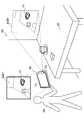
図1は、既存の手法におけるARコンテンツの投影について説明するための説明図である。図1を参照すると、ユーザUaが有する画像処理装置10が示されている。画像処理装置10は、画像を表示する表示部11と、例えば表示部11の背面に設けられ、実空間20を撮像する撮像部(図示せず)と、画像を投影する投影部13と、を備える。図1の例において、実空間20には、実物体であるテーブル21が存在している。画像処理装置10の制御部(図示せず)は、撮像される画像を入力画像として受け取り、拡張現実(AR)アプリケーションを動作させる。表示部11は、ARアプリケーションによって仮想オブジェクトの重畳された画像を表示する。図1の例では、画像Im01が表示されており、テーブル21の上に仮想オブジェクトV1があたかも存在するかのように、画像Im01に仮想オブジェクトV1が重畳されている。投影部13は、このような画像Im01を実空間内の投影面(例えば、壁面、床面又は実物体の表面)に投影する。図1の例では、画像Im01が壁面に投影されている。 FIG. 1 is an explanatory diagram for explaining projection of AR content in an existing method. Referring to FIG. 1, there is shown an
第三者、即ちユーザUa以外の人物は、投影された画像Im01を見ることにより、ユーザUaにどのようなARコンテンツが提供されているかを知ることができる。しかし、画像Im01内の仮想オブジェクトV1は、実空間20内のテーブル21の上には存在しない。従って、第三者には、“拡張現実感”、即ち現実世界が拡張されたかのような感覚は与えられない。 A third party, that is, a person other than the user Ua, can see what AR content is provided to the user Ua by looking at the projected image Im01. However, the virtual object V1 in the image Im01 does not exist on the table 21 in the
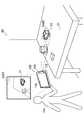
図2は、一実施形態に係る画像処理装置100の概要について説明するための説明図である。図2を参照すると、図1と同様の実空間20内でユーザUaが有する画像処理装置100が示されている。画像処理装置100は、撮像部102、表示部110及び投影部112を備える。画像処理装置100の制御部(図示せず)は、撮像部102により撮像される画像を入力画像として受け取り、ARアプリケーションを動作させる。表示部110は、ARアプリケーションによって仮想オブジェクトの重畳された画像(例えば、画像Im01)を表示する。投影部112は、表示部110により表示される画像Im01の代わりに、投影のために適合される画像Im02を投影する。図3の例では、AR空間内の仮想オブジェクトV1の表示位置に対応するテーブル21上の3次元位置に、仮想オブジェクトV1を表現する画像Im02が投影されている。 FIG. 2 is an explanatory diagram for explaining an overview of the
第三者は、画像Im02を見ることにより、ユーザUaと同様に、テーブル21の上に仮想オブジェクトV1があたかも存在するかのような感覚を体験することができる。それにより、ユーザUaと第三者との拡張現実感の共有が実現される。また、公共の場においてARアプリケーションの対象物に仮想オブジェクトが投影されれば、カメラをかざすユーザの行動の意図を第三者に理解させることができる。それにより、第三者に不審な感情を与えることを防止し、又は第三者の興味を引き起こしてARアプリケーションへの参加を促すことができる。 By viewing the image Im02, the third party can experience the sensation as if the virtual object V1 exists on the table 21, like the user Ua. Thereby, sharing of augmented reality between the user Ua and a third party is realized. In addition, if a virtual object is projected onto a target object of an AR application in a public place, the intention of the user's action over the camera can be understood by a third party. Thereby, it is possible to prevent a suspicious feeling from being given to a third party, or to cause the third party to be interested and encourage participation in the AR application.
このような投影を実現するための装置の構成について、次節でより詳細に説明する。なお、拡張現実のための仮想オブジェクトの投影には、例えば、投影解像度、環境認識の精度、プライバシー、及び投影状態の安定化など、いくつかの特有の課題が伴う。それら課題への対策もまた、本開示において提供される。 The configuration of the apparatus for realizing such projection will be described in more detail in the next section. Note that the projection of a virtual object for augmented reality involves several unique problems such as, for example, projection resolution, accuracy of environment recognition, privacy, and stabilization of the projection state. Countermeasures for these issues are also provided in this disclosure.
図2では、画像処理装置100の一例として携帯端末を示している。しかしながら、画像処理装置100は、かかる例に限定されない。画像処理装置100は、例えば、PC(Personal Computer)、PDA(Personal Digital Assistant)、スマートフォン、ゲーム端末、PND(Portable Navigation Device)、コンテンツプレーヤ又はデジタル家電機器などであってもよい。また、ARアプリケーションは、ユーザにより操作される端末上で動作する代わりに、端末との間で通信可能な他の装置(例えば、アプリケーションサーバ)上で動作してもよい。 In FIG. 2, a mobile terminal is shown as an example of the
<2.一実施形態に係る装置の構成>
[2−1.ハードウェア構成]
図3は、一実施形態に係る画像処理装置100のハードウェア構成の一例を示すブロック図である。図3を参照すると、画像処理装置100は、撮像部102、センサ部104、入力部106、記憶部108、表示部110、投影部112、通信部114、バス116及び制御部118を備える。<2. Configuration of Device According to One Embodiment>
[2-1. Hardware configuration]
FIG. 3 is a block diagram illustrating an example of a hardware configuration of the
(1)撮像部
撮像部102は、画像を撮像するカメラモジュールである。撮像部102は、CCD(Charge Coupled Device)又はCMOS(Complementary Metal Oxide Semiconductor)などの撮像素子を用いて実空間を撮像し、撮像画像を生成する。撮像部102により生成される撮像画像は、制御部118により実行される処理の入力画像となる。なお、撮像部102は、必ずしも画像処理装置100の一部でなくてもよい。例えば、画像処理装置100と有線又は無線で接続される撮像装置が撮像部102として扱われてもよい。(1) Imaging unit The
(2)センサ部
センサ部104は、測位センサ(例えば、GPS(Global Positioning System)モジュールなど)、地磁気センサ、加速度センサ及びジャイロセンサなどの様々なセンサを含み得る。測位センサは、端末の現在位置を測定する。地磁気センサは、端末の現在の姿勢(方位)を測定する。センサ部104において得られる測定結果は、地理的な位置に特化したデータの取得、環境認識の支援、又はユーザ入力の検出などの様々な用途のために利用されてよい。なお、センサ部104は、画像処理装置100の構成から省略されてもよい。(2) Sensor Unit The
(3)入力部
入力部106は、ユーザが画像処理装置100を操作し又は画像処理装置100へ情報を入力するために使用される入力デバイスである。入力部106は、例えば、表示部110の画面上へのユーザによるタッチを検出するタッチセンサを含んでもよい。その代わりに(又はそれに加えて)、入力部106は、マウス又はタッチパッドなどのポインティングデバイスを含んでもよい。さらに、入力部106は、キーボード、キーパッド、ボタン又はスイッチなどのその他の種類の入力デバイスを含んでもよい。(3) Input unit The
(4)記憶部
記憶部108は、半導体メモリ又はハードディスクなどの記憶媒体により構成され、画像処理装置100による処理のためのプログラム及びデータを記憶する。記憶部108により記憶されるデータは、例えば、撮像画像データ、センサデータ及び後に説明する様々なデータベース(DB)内のデータを含み得る。なお、本明細書で説明するプログラム及びデータの一部は、記憶部108により記憶されることなく、外部のデータソース(例えば、データサーバ、ネットワークストレージ又は外付けメモリなど)から取得されてもよい。(4) Storage Unit The
(5)表示部
表示部110は、LCD(Liquid Crystal Display)、OLED(Organic light-Emitting Diode)又はCRT(Cathode Ray Tube)などのディスプレイを含む表示モジュールである。表示部110は、例えば、画像処理装置100により生成されるARアプリケーションの画像を表示するために使用される。なお、表示部110もまた、必ずしも画像処理装置100の一部でなくてもよい。例えば、画像処理装置100と有線又は無線で接続される表示装置が表示部110として扱われてもよい。(5) Display Unit The
(6)投影部
投影部112は、液晶プロジェクタ、DLP(Digital Light Processing)プロジェクタ(登録商標)又はLCOS(Liquid Crystal On Silicon)プロジェクタなどのプロジェクタモジュールである。投影部112は、例えば、画像処理装置100により生成されるARアプリケーションの仮想オブジェクトを実空間内の投影面に投影するために使用される。なお、投影部112もまた、必ずしも画像処理装置100の一部でなくてもよい。例えば、画像処理装置100と有線又は無線で接続される投影装置が投影部112として扱われてもよい。(6) Projection Unit The
(7)通信部
通信部114は、画像処理装置100による他の装置との間の通信を仲介する通信インタフェースである。通信部114は、任意の無線通信プロトコル又は有線通信プロトコルをサポートし、他の装置との間の通信接続を確立する。(7) Communication Unit The
(8)バス
バス116は、撮像部102、センサ部104、入力部106、記憶部108、表示部110、投影部112、通信部114及び制御部118を相互に接続する。(8) Bus The
(9)制御部
制御部118は、CPU(Central Processing Unit)又はDSP(Digital Signal Processor)などのプロセッサに相当する。制御部118は、記憶部108又は他の記憶媒体に記憶されるプログラムを実行することにより、後に説明する画像処理装置100の様々な機能を動作させる。(9) Control Unit The
[2−2.プロジェクタ出力用の座標変換]
本実施形態において、撮像部102及び投影部112の物理的配置は予め校正されており、撮像部102と投影部112との間の相対的な位置及び姿勢が画像処理装置100にとって既知であるものとする。図4は、撮像部102及び投影部112の物理的配置の一例を示している。[2-2. Coordinate transformation for projector output]
In this embodiment, the physical arrangement of the
図4を参照すると、端末の筐体の一面に、撮像部102のレンズ及び投影部112のレンズが並置されている。撮像部102の光軸及び投影部112の光軸は、おおよそ同じ方向に向けられる。撮像部102のレンズの背後には、多数の撮像素子が配設される撮像面IPが設置される。画像処理装置100により入力画像内で認識される実物体の位置(及び姿勢)は、撮像面の座標系Uc(u,v)で2次元的に表現され、及び実空間の座標系Xc(xc,yc,zc)で3次元的に表現される。2次元座標系Ucと3次元座標系Xcとの間の関係は、例えば、いわゆるピンホールモデルに従って幾何的に与えられる。ARアプリケーションは、実物体の位置及び姿勢に基づいて、仮想オブジェクトの3次元的な配置を決定する。決定された3次元的な配置から、仮想オブジェクトの2次元画像を生成することができる。ここで、投影部112が撮像部102と物理的に完全に同じ位置には設置されない点に留意すべきである。ディスプレイ出力用に生成される2次元画像をそのまま投影部112に投影させるのは、適切でない。そこで、画像処理装置100は、座標変換パラメータTc_p及びRc_pを用いて、ディスプレイ出力用の仮想オブジェクトの配置Vcを、プロジェクタ出力用の配置Vpに変換する。座標変換パラメータは、例えば、撮像部102を基準とする座標系Xc(xc,yc,zc)と投影部112を基準とする座標系Xp(xp,yp,zp)との間の変換(並進、回転及びスケーリング)を表す座標変換行列であってよい。座標変換パラメータの既定値は、撮像部102と投影部112との間の校正された相対的な位置関係に応じて予め決定され、例えば記憶部108により記憶される。Referring to FIG. 4, the lens of the
なお、投影部112は、一般的なプロジェクタモジュールと同様、投影スケール(ズーム率)及びフォーカス位置を調整するための固有の機構を有し得る。例えば、投影部112の当該機構が駆動されることにより投影スケールが変更されると、座標変換パラメータは、投影スケールの変化量に応じて再計算され得る。後に詳細に説明するように、画像処理装置100は、投影の状態を良好に保つために、これら機構をも活用し得る。 Note that the
[2−3.機能構成]
図5は、図3に示した画像処理装置100の記憶部108及び制御部118により実現される論理的機能の構成の一例を示すブロック図である。図5を参照すると、画像処理装置100は、画像取得部120、データ取得部130、環境認識部140、環境データベース(DB)145、オブジェクト制御部150、コンテンツDB155、表示制御部160、投影制御部170及びユーザインタフェース部180を有する。[2-3. Functional configuration]
FIG. 5 is a block diagram illustrating an example of a configuration of logical functions realized by the
(1)画像取得部
画像取得部120は、撮像部102により生成される撮像画像を入力画像として取得する。画像取得部120により取得される入力画像は、実空間を映した画像である。当該入力画像は、静止画であってもよく、又は動画を構成する各フレームであってもよい。画像取得部120は、取得した入力画像を、環境認識部140及び表示制御部160へ出力する。(1) Image Acquisition Unit The
(2)データ取得部
データ取得部130は、環境の認識、及び仮想オブジェクトの表示又は投影の制御などの様々な目的のために使用されるデータを取得する。例えば、データ取得部130は、センサ部104により生成されるセンサデータ(例えば、位置データ及び姿勢データ)を取得してもよい。また、データ取得部130は、端末の現在位置の近傍に存在する実物体に関するデータを、端末の現在位置を用いて外部のデータサーバに問合せを行うことにより取得してもよい。(2) Data Acquisition Unit The
(3)環境認識部
環境認識部140は、入力画像に映る1つ以上の実物体を認識する。また、環境認識部140は、認識した実物体と撮像部102との間の相対的な位置関係(位置及び姿勢)を認識する。そして、環境認識部140は、環境認識の結果を環境DB145に記憶させる。(3) Environment Recognition Unit The
例えば、環境認識部140は、各実物体の識別子と実空間内の位置とを関連付けるマップデータを取得する。また、環境認識部140は、センサデータに基づいて撮像部102の位置及び姿勢を認識する。そして、環境認識部140は、撮像部102の位置及び姿勢から推定されるカメラアングルをマップデータと照合することにより、カメラアングル内のどこに実物体が存在するかを認識し得る。 For example, the
その代わりに、環境認識部140は、より高度な環境認識技術を活用してもよい。例えば、環境認識部140は、実物体の特徴量を記述するモデルデータを取得する。そして、環境認識部140は、入力画像から抽出される特徴量とモデルデータにより記述される特徴量とを照合することにより、入力画像のどこにどのような姿勢で実物体が映っているかを認識し得る。公知の環境認識技術とは、例えば、SURF法(H.Bay, A.Ess, T.Tuytelaars and L.V.Gool, “Speeded-Up Robust Features (SURF)”, Computer Vision - ECCV,2006参照)又はSLAM法(Andrew J.Davison,“Real-Time Simultaneous Localization and Mapping with a Single Camera”,Proceedings of the 9th IEEE International Conference on Computer Vision Volume 2, 2003, pp.1403-1410参照)などであってよい。 Instead, the
環境DB145は、環境認識部140による環境認識の結果を記憶するデータベースである。環境DB145により記憶される環境認識の結果は、例えば、撮像部102の位置及び姿勢を基準とする、認識された実物体の相対的な位置及び姿勢を含み得る。実物体の位置及び姿勢は、図4を用いて説明した3次元座標系Xcで表現されてよい。The
(4)オブジェクト制御部
オブジェクト制御部150は、環境認識部140により認識される実物体の位置及び姿勢に従って、当該実物体と関連付けられる拡張現実のための仮想オブジェクトの配置を決定する。より具体的には、オブジェクト制御部150は、例えば、認識された実物体と関連付けられている仮想オブジェクトのデータをコンテンツDB155から取得する。また、オブジェクト制御部150は、当該実物体の位置及び姿勢を、環境DB145から取得する。そして、オブジェクト制御部150は、実物体の位置及び姿勢に従って、仮想オブジェクトの配置を決定する(図2の例では、テーブル21の上に仮想オブジェクトV1が配置されている)。そして、オブジェクト制御部150は、表示すべき仮想オブジェクトの識別子とその3次元的な配置とを表示制御部160へ出力する。(4) Object Control Unit The
また、オブジェクト制御部150は、後に詳細に説明する表示モードに応じて、仮想オブジェクトを変化させる。ある表示モードにおいて、仮想オブジェクトを重畳するための画像は、表示制御部160から表示部110へ出力される。他の表示モードにおいて、仮想オブジェクトを重畳するための画像は、表示制御部160から投影部112へ出力される。オブジェクト制御部150は、例えば、出力先が投影部112である場合に、出力先が表示部110である場合よりも簡易な仮想オブジェクトを、投影される仮想オブジェクトとして選択してもよい。また、オブジェクト制御部150は、出力先が投影部112である場合に、仮想オブジェクトの少なくとも1つの表示属性を、投影の解像度に応じて調整してもよい。また、オブジェクト制御部150は、投影される仮想オブジェクトを原因として環境認識部140による認識処理の精度が低下すると判定される場合に、当該仮想オブジェクトの少なくとも1つの表示属性を調整し、又は当該仮想オブジェクトの位置を移動させてもよい。さらに、オブジェクト制御部150は、投影される情報について予め設定され又は動的に指定されるプライバシーレベルに従って、仮想オブジェクトにより示される情報を変化させてもよい。 Further, the
コンテンツDB155は、各実物体と関連付けられる仮想オブジェクトについてのデータを蓄積しているデータベースである。図6は、コンテンツDB155のデータ構成の一例を示す説明図である。図6を参照すると、コンテンツDB155は、コンテンツID155a、カテゴリ155b、関連物体155c、既定の配置155d、表示データ155e及び投影データ155fという6つのデータ項目を有する。 The
コンテンツID155aは、各仮想オブジェクトを一意に識別するための識別子である。カテゴリ155bは、各仮想オブジェクトの種類を表す。関連物体155cは、各仮想オブジェクトと関連付けられる実物体の識別子である。1つの実物体に、複数の仮想オブジェクトが関連付けられてもよい。既定の配置155dは、各仮想オブジェクトの既定の配置(関連付けられる実物体に対する相対的な位置、姿勢及びスケール)を表す。表示データ155eは、各仮想オブジェクトのディスプレイ出力用のデータの実体である。投影データ155fは、各仮想オブジェクトのプロジェクタ出力用のデータの実体である。個々のデータは、テキスト形式、イメージ形式又は外部のデータソースへのリンク形式など、いかなる形式で記述されてもよい。 The
図6の例において、コンテンツID=“C4”を有する仮想オブジェクトのディスプレイ出力用のデータがレストランについてのレビューコメントのテキストを含む一方で、当該仮想オブジェクトのプロジェクタ出力用のデータはレーティングに対応する数の星印のアイコンイメージのみを含む。このように、プロジェクタ出力用のARコンテンツをディスプレイ出力用のARコンテンツよりも簡易な内容とすることで、表示画像よりも通常低い解像度しか期待できない投影画像においてARコンテンツを判別することが困難となることを避けることができる。 In the example of FIG. 6, the display output data of the virtual object having the content ID = “C4” includes the text of the review comment about the restaurant, while the projector output data of the virtual object is a number corresponding to the rating. Only the icon image of the star is included. Thus, by making the AR content for projector output simpler than the AR content for display output, it becomes difficult to discriminate the AR content in a projection image that can normally be expected to have a lower resolution than the display image. You can avoid that.
図6から理解されるように、投影データ155fは、1つの仮想オブジェクトについて複数のデータの実体を格納することができる。これら複数のデータは、例えば、異なる投影解像度又は異なるプライバシーレベルに対応するデータであってよい。 As can be understood from FIG. 6, the
オブジェクト制御部150は、このようなデータ構成を有するコンテンツDB155を用いて、表示され又は投影される仮想オブジェクトを制御する。なお、図6の例のように1つの仮想オブジェクトについて複数のデータが予めデータベース内に記憶される代わりに、オブジェクト制御部150は、1つのデータから他のデータを動的に生成してもよい。オブジェクト制御部150による仮想オブジェクトの制御について、後にさらに説明する。 The
(5)表示制御部
表示制御部160は、第1の表示モードにおいて、仮想オブジェクトを重畳するための出力画像を表示部110へ出力し、表示部110の画面上に当該出力画像を表示させる。また、表示制御部160は、第2の表示モードにおいて、仮想オブジェクトを重畳するための出力画像を投影部112へ出力し、投影部112に実空間内の投影面へ当該出力画像を投影させる。表示部110及び投影部112へ並列的に画像が出力される第3の表示モードがサポートされてもよい。表示制御部160によりサポートされ得るこれら表示モードについて、後に図面を用いてさらに説明する。(5) Display Control Unit In the first display mode, the
仮想オブジェクトのAR空間内の3次元的な配置は、環境認識の結果とコンテンツDB155内のデータ(例えば、既定の配置155d)とに基づいて、オブジェクト制御部150により決定される。表示制御部160は、例えばピンホールモデルに従って、仮想オブジェクトの3次元的な配置から、仮想オブジェクトの2次元画像を生成する。表示制御部160から表示部110へ出力される出力画像は、例えば、当該2次元画像を入力画像に重畳することにより生成され得る。また、表示制御部160は、上述した座標変換パラメータを用いて、仮想オブジェクトの配置を、投影部112への出力のために変換する。表示制御部160から投影部112へ出力される出力画像は、当該変換後の配置に従って生成される仮想オブジェクトの2次元画像であってよい。 The three-dimensional arrangement of the virtual object in the AR space is determined by the
(6)投影制御部
投影制御部170は、環境認識部140により認識される撮像部102の位置又は姿勢に基づいて、投影部112による投影を制御する。より具体的には、投影制御部170は、投影部112固有の制御パラメータ(以下、投影制御パラメータという)を通じて調整され得る基準状態に投影の状態が維持されるように、投影を制御する。以下の説明において、投影制御パラメータは、図4を用いて説明した投影スケール及びフォーカス位置を含むものとする。なお、かかる例に限定されず、投影制御パラメータは、台形補正及び輝度などのその他の種類のパラメータを含んでもよい。(6) Projection Control Unit The
投影の状態とは、投影面上の仮想オブジェクトの解像度、サイズ、完全性及びフォーカス状態などを含み得る。 The state of projection may include the resolution, size, completeness, focus state, etc. of the virtual object on the projection plane.
例えば、他の条件が一定であれば、投影部112と投影面を有する実物体との間の距離が増加するにつれて、投影解像度は低下する。そこで、投影制御部170は、上記距離の増加に従って投影スケールを縮小することにより、投影解像度の低下を回避する。また、投影部112と投影面を有する実物体との間の距離が減少すると、仮想オブジェクトが投影アングル内に収まりきらず、仮想オブジェクトが欠損する(即ち、仮想オブジェクトの完全性が失われる)可能性がある。そこで、投影制御部170は、上記距離の減少に従って投影スケールを拡大することにより、仮想オブジェクトの欠損を回避する。いずれのケースでも、投影制御部170は、オブジェクト制御部150と連携することにより、投影面上の仮想オブジェクトの実サイズ(投影サイズ)の拡大又は縮小を相殺するように、仮想オブジェクトの投影アングルに対する相対的なサイズを変化させる。 For example, if other conditions are constant, the projection resolution decreases as the distance between the
また、仮想オブジェクトが鮮明に投影されるように一旦フォーカス位置が調整されたとしても、その後に投影部112と実物体との間の距離が変化すれば、フォーカスはズレた状態となり得る。そこで、投影制御部170は、上記距離の変動に関わらず、投影される仮想オブジェクトのフォーカス状態が維持されるように、フォーカス位置を制御する。 Moreover, even if the focus position is once adjusted so that the virtual object is projected clearly, if the distance between the
本実施形態において、投影制御部170による投影の制御は、調整フェーズと維持フェーズという2つのフェーズを含む。調整フェーズにおいて、投影の状態は、必ずしも維持されない。むしろ、ユーザによる投影制御パラメータの調整に従って、投影制御部170は、投影の状態を変化させる。例えば、ユーザは、ユーザインタフェースを介して投影スケールを調整することにより、仮想オブジェクトの投影サイズを拡大し又は縮小することができる。また、ユーザは、ユーザインタフェースを介してフォーカス位置を調整することにより、仮想オブジェクトフォーカス状態を変更することができる。所定のユーザ入力が検出されると、投影の制御は、調整フェーズから維持フェーズへと遷移する。上記ユーザ入力の検出の時点での投影の状態は、維持フェーズにおいて基準状態として扱われる。上記ユーザ入力の検出の時点での投影制御パラメータの値は、制御の基準値として保持され得る。維持フェーズにおいて、投影制御部170は、例えば投影部112と実物体との間の距離の変動に関わらず、投影の状態が基準状態に維持されるように、投影スケール及びフォーカス位置を制御する。なお、投影制御パラメータの既定値を制御の基準値として用いることにより、調整フェーズがスキップされてもよい。 In the present embodiment, projection control by the
投影制御部170は、このようにユーザにより調整され又は動的に制御される投影制御パラメータの値を投影部112に設定し、投影部112の固有の機構を駆動する。それにより、上述した投影の状態が維持される。投影制御部170により実行されるこのような投影制御の例について、後に図面を用いてさらに説明する。 In this way, the
(7)ユーザインタフェース部
ユーザインタフェース部180は、ARアプリケーションのための様々なユーザインタフェース(UI)をユーザに提供する。例えば、ユーザインタフェース部180により提供されるUIは、複数のモードの間で表示モードを切り替えるためのUI、プライバシーレベルをユーザに指定させるためのUI、投影制御パラメータをユーザに調整させるためのUI、及び投影制御のフェーズを遷移させるためのUIを含み得る。各UIは、例えば、画面上に表示されるグラフィカルユーザインタフェース(GUI)であってもよく、又はタッチセンサを用いて実現されるタッチUIであってもよい。各UIは、スイッチ若しくはボタンなどの物理的なUI、又は音声コマンドを認識することにより実現される音声UIであってもよい。(7) User Interface Unit The
[2−4.様々な表示モード]
図7A〜図7Cは、表示制御部160によりサポートされ得る表示モードの3つの例をそれぞれ示している。[2-4. Various display modes]
7A to 7C show three examples of display modes that can be supported by the
図7Aに示した表示モードM1は、ディスプレイオンリーモードである。表示制御部160は、表示モードM1を指定するモード切替信号SWが入力されると、ディスプレイオンリーモードに遷移し得る。モード切替信号SWは、所定のユーザ入力に応じて生成され得る。ディスプレイオンリーモードにおいて、表示制御部160は、仮想オブジェクトを重畳するための画像を表示部110へ出力する一方で、投影部112へ画像を出力しない。 The display mode M1 shown in FIG. 7A is a display-only mode. When the mode switching signal SW designating the display mode M1 is input, the
図7Bに示した表示モードM2は、デュアルモードである。表示制御部160は、表示モードM2を指定するモード切替信号SWが入力されると、デュアルモードに遷移し得る。デュアルモードにおいて、表示制御部160は、仮想オブジェクトを重畳するための画像を表示部110へ出力すると共に、同じ仮想オブジェクト又は異なる仮想オブジェクトを重畳するための画像を、投影部112へ出力する。 The display mode M2 shown in FIG. 7B is a dual mode. When the mode switching signal SW for designating the display mode M2 is input, the
図7Cに示した表示モードM3は、プロジェクタオンリーモードである。表示制御部160は、表示モードM3を指定するモード切替信号SWが入力されると、プロジェクタオンリーモードに遷移し得る。プロジェクタオンリーモードにおいて、表示制御部160は、仮想オブジェクトを重畳するための画像を投影部112へ出力する一方で、表示部110へ画像を出力しない。 The display mode M3 shown in FIG. 7C is a projector only mode. When the mode switching signal SW for designating the display mode M3 is input, the
なお、これら表示モードは例に過ぎない。即ち、他の追加的な表示モードがサポートされてもよく、又はいずれかの表示モードがサポートされなくてもよい。 These display modes are merely examples. That is, other additional display modes may be supported, or any display mode may not be supported.
[2−5.投影される仮想オブジェクトの制御]
上述したように、オブジェクト制御部150は、画像の出力先が表示部110及び投影部112のいずれであるかに応じて、表示され又は投影される仮想オブジェクトを変化させる。なお、本明細書において、「仮想オブジェクトを変化させる」との用語は、ある仮想オブジェクトの代わりに他の仮想オブジェクトを用いることに加えて、ある仮想オブジェクトの配置、属性又は当該仮想オブジェクトにより示される情報を変更することをも含むものとする。[2-5. Control of projected virtual object]
As described above, the
(1)簡易な仮想オブジェクトの投影
例えば、オブジェクト制御部150は、出力先が投影部112である場合には、出力先が表示部110である場合よりも簡易な仮想オブジェクトを、投影される仮想オブジェクトとして選択してよい。簡易な仮想オブジェクトとは、例えば、ARアプリケーションにおいて注目されている場所(表示部110の画面上で仮想オブジェクトが重畳される場所)を第三者に単に通知するだけの標識(indication)であってもよい。当該標識は、例えば、仮想オブジェクトと関連付けられる実物体を囲む枠又は当該実物体を指し示すアイコンなどであってよい。このような簡易な仮想オブジェクトの投影によって、ARアプリケーションのユーザがどの実物体に注目しているかを、第三者が知ることができる。また、ARコンテンツの詳細を第三者に秘匿することにより、ユーザのプライバシーを保護することができる。(1) Simple Projection of Virtual Object For example, when the output destination is the
(2)投影解像度に応じた制御
また、オブジェクト制御部150は、出力先が投影部112である場合に、投影される仮想オブジェクトを、投影解像度に応じて変化させてもよい。(2) Control According to Projection Resolution Further, when the output destination is the
図8は、投影解像度に応じた仮想オブジェクトの制御について説明するための説明図である。図8を参照すると、実物体22により近い位置PT01に位置する画像処理装置100、及び実物体22からより遠い位置PT02に位置する画像処理装置100が示されている。実物体22の一面は、仮想オブジェクトの投影面である。一般的に、投影面からの距離がより大きければ、投影解像度はより低くなる。本実施形態においても、特に調整フェーズでは、投影解像度を維持するように投影スケールが制御されないため、投影解像度の低下は避けられない。そして、仮想オブジェクトのグラフィックとしての空間解像度を投影解像度が下回ると、投影される仮想オブジェクトの細部が視認困難となる(例えば、文字つぶれが発生し得る)可能性がある。そこで、オブジェクト制御部150は、例えば環境認識部140による環境認識の結果を用いて、投影面を有する実物体と投影部112との間の距離を計算し、計算した距離に基づいて、投影解像度を推定する。上記距離と投影解像度との間のマッピングを示すデータが、予め記憶されていてもよい。そして、オブジェクト制御部150は、推定した投影解像度が仮想オブジェクトの空間解像度を下回る場合に、投影される仮想オブジェクトを変化させる。例えば、オブジェクト制御部150は、仮想オブジェクトのポリゴン数を削減し、又は複雑なグラフィックを有する仮想オブジェクトを簡易なアイコンなどに切り替えてもよい。図8の例では、仮想オブジェクトV2bが、位置PT02に位置する画像処理装置100により実物体22へ投影されている。仮想オブジェクトV2bは、例えばポリゴンが削減された結果として、位置PT01に位置する画像処理装置100により投影される仮想オブジェクトV2aよりも低い空間解像度を有する。FIG. 8 is an explanatory diagram for explaining the control of the virtual object according to the projection resolution. Referring to FIG. 8, an
(3)認識精度の低下の防止
また、オブジェクト制御部150は、投影される仮想オブジェクトを原因として環境認識部140による認識処理の精度が低下すると判定される場合に、当該仮想オブジェクトの少なくとも1つの表示属性を調整し、又はその位置を移動させてもよい。ここでの表示属性とは、例えば、仮想オブジェクトの輝度、色又はコントラストを含み得る。(3) Prevention of reduction in recognition accuracy When the
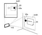
図9Aは、認識精度の低下を防止するための仮想オブジェクトの制御の第1の例について説明するための説明図である。図9Aを参照すると、表示部110により画面上に表示される画像Im31、及び投影部112により投影される画像Im32が示されている。画像Im31において、実物体23に仮想オブジェクトV3aが重畳されている。また、画像Im32により、実空間内の実物体23に仮想オブジェクトV3bが重畳される。投影される仮想オブジェクトV3bの輝度は、画面上に表示される仮想オブジェクトV3aの輝度よりも低減される。それにより、実物体23に投影光が当たる結果として環境認識部140による実物体23の認識が困難となることを防止することができる。オブジェクト制御部150は、輝度の代わりに、投影される仮想オブジェクトのコントラストを低減してもよく、又は、いわゆるカラーイコライゼーション処理によって仮想オブジェクトの色を投影面の色に合わせて調整してもよい。 FIG. 9A is an explanatory diagram for describing a first example of virtual object control for preventing a reduction in recognition accuracy. Referring to FIG. 9A, an image Im31 displayed on the screen by the
図9Bは、認識精度の低下を防止するための仮想オブジェクトの制御の第2の例について説明するための説明図である。図9Bを参照すると、図9Aと同様に画面上に表示される画像Im31、及び投影部112により投影される画像Im33が示されている。画像Im33により、実物体23ではなく、実物体23の近傍の投影面に仮想オブジェクトV3cが投影されている。即ち、仮想オブジェクトV3cの位置は、画面上に表示される仮想オブジェクトV3aの表示位置から移動されている。この場合には、実物体23に投影光が当たることが回避されるため、環境認識部140による実物体23の認識が困難となることを防止することができる。なお、オブジェクト制御部150は、例えば画面上でのフリック又はドラッグなどのユーザ入力に応じて、仮想オブジェクトV3cの位置を移動させてもよい。 FIG. 9B is an explanatory diagram for describing a second example of virtual object control for preventing a reduction in recognition accuracy. Referring to FIG. 9B, an image Im31 displayed on the screen and an image Im33 projected by the
(4)プライバシーレベルに従った制御
また、オブジェクト制御部150は、出力先が投影部112である場合に、投影部112により投影される情報について予め設定され又は動的に指定されるプライバシーレベルに従って、投影される仮想オブジェクトを変化させてもよい。(4) Control according to privacy level When the output destination is the
図10A及び図10Bは、ユーザにより指定されるプライバシーレベルに従った仮想オブジェクトの制御の2つの例を示している。図10Aの左には、実物体24を撮像する画像処理装置100が示されている。実物体24は、カレンダーである。表示部110の画面上において、カレンダー24に仮想オブジェクトV4aが重畳されている。仮想オブジェクトV4aは、カレンダー24に記載された日付に関連付けられるスケジュールアイテムの詳細情報(例えば、ミーティングの場所、参加者など)を示している。一方、実空間内のカレンダー24には仮想オブジェクトV4cが投影されている。仮想オブジェクトV4cは、カレンダー24に記載された日付に関連付けられるスケジュールアイテムが存在することを単に通知する簡易なアイコンである。 FIGS. 10A and 10B show two examples of virtual object control according to the privacy level specified by the user. On the left side of FIG. 10A, an
ここで、例えばユーザインタフェース部180により所定のユーザ入力が検出されると、プライバシーレベルの設定が変更される。図10Aの例では、タッチジェスチャの一種であるピンチアウトが検出されている。本実施形態において、ピンチアウトは、プライバシーレベルの引き下げを意味し得る。ピンチアウトの検出に応じて、オブジェクト制御部150は、仮想オブジェクトV4cを仮想オブジェクトV4bに変更する。図10Aの右に示すカレンダー24には、仮想オブジェクトV4bが投影されている。仮想オブジェクトV4bは、カレンダー24に記載された日付に関連付けられるスケジュールアイテムの件名(例えば、“ミーティング”)を示している。図示された操作とは逆に、オブジェクト制御部150は、例えば、ピンチインの検出に応じてプライバシーレベルを引き上げ、仮想オブジェクトV4bを仮想オブジェクトV4cに変更してもよい。 Here, for example, when a predetermined user input is detected by the
図10Bの左には、カレンダー24を撮像する画像処理装置100が再び示されている。表示部110の画面上において、カレンダー24に仮想オブジェクトV4aが重畳されている。一方、実空間内のカレンダー24には仮想オブジェクトV4bが投影されている。画面の右端には、ユーザがプライバシーレベルを指定するためのGUIであるスライダUI0が表示されている。スライダU10がユーザにより下方へドラッグされ、又はタップされると、プライバシーレベルの設定が引き下げられる。それに応じて、オブジェクト制御部150は、仮想オブジェクトV4bを仮想オブジェクトV4aに変更する。図10Bの右に示すカレンダー24には、画面上に表示されているものと同じ仮想オブジェクトV4aが投影されている。 The
このようなプライバシーレベルに従った制御によれば、ARアプリケーションのユーザが、第三者とのARコンテンツの共有レベルをプライバシーの観点で柔軟に指定することが可能となる。 According to such control according to the privacy level, the user of the AR application can flexibly specify the sharing level of the AR content with the third party from the viewpoint of privacy.
本項で説明した投影される仮想オブジェクトの様々な制御は、どのような形で互いに組み合わされてもよい。 The various controls of the projected virtual object described in this section may be combined with each other in any way.
[2−6.投影制御パラメータの活用]
本開示に係る技術が携帯端末を用いて実現される場合、携帯端末の位置及び姿勢は、ユーザの意図に沿って又はその意図に反して、ARアプリケーションの動作中に変動し得る。そして、環境認識部140による認識処理が適切に動作している限り、端末の位置及び姿勢の変動は正確に認識され、仮想オブジェクトの表示の状態は正常に保たれる。しかし、端末の位置及び姿勢の変動が正確に認識されていても、ある条件下で、仮想オブジェクトの投影の状態は不適切となり得る。そこで、投影制御部170は、上述したように、投影部112固有の投影制御パラメータを活用し、投影の状態が適切に維持されるように投影を制御する。[2-6. Utilization of projection control parameters]
When the technology according to the present disclosure is implemented using a mobile terminal, the position and orientation of the mobile terminal may vary during the operation of the AR application along or against the user's intention. Then, as long as the recognition processing by the
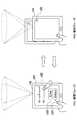
図11Aは、投影の状態が不適切となり得る状況の第1の例について説明するための説明図である。図11Aの左には、実物体25を撮像する画像処理装置100が示されている。実物体25には、仮想オブジェクトV5aが投影されている。この時点で、投影スケールScの値は、Sc=sc1であるものとする。投影アングルPA1は、投影スケールの値に対応する。図11Aの右には、実物体25からより遠くに位置する画像処理装置100が示されている。環境認識部140は、実物体25との間の距離の変化を認識する。それに応じて、オブジェクト制御部150は、投影アングルPA1に対する仮想オブジェクトの相対的なサイズを縮小する。結果的に、実物体25には、仮想オブジェクトV5bが投影されている。仮想オブジェクトV5bの投影サイズ(投影面上での実サイズ)は、仮想オブジェクトV5aの投影サイズと等しい。しかし、投影アングルに対する仮想オブジェクトの相対的なサイズの縮小は、投影解像度の低下を招く。そして、仮想オブジェクトV5bが複雑なグラフィックを有する場合には、そのグラフィックの細部が視認困難となる(例えば、文字つぶれが起こる、など)可能性がある。特に、上述したような仮想オブジェクトの切り替えなどの対策が行われないようなケースでは、こうした投影解像度の低下は避けられることが望ましい。 FIG. 11A is an explanatory diagram for describing a first example of a situation where a projection state may be inappropriate. On the left of FIG. 11A, an
図11Bは、図11Aの状況において投影の状態を適切に維持するための制御について説明するための説明図である。図11Bの左には、図11Aの右に示した通りの投影解像度が低下した状況が、再び示されている。図11Bの右の画像処理装置100の実物体25からの距離は、図11Aの左における当該距離と等しい。投影制御部170は、環境認識の結果に基づいて取得される距離の増加に応じて、投影スケールScの値を、sc1からsc2へ縮小する。それに応じて、投影アングルPA2は、投影アングルPA1よりも狭くなる。投影アングルに対する仮想オブジェクトの相対的なサイズは、拡大される。結果的に、実物体25には、仮想オブジェクトV5cが投影されている。仮想オブジェクトV5cの投影サイズは、仮想オブジェクトV5a及びV5bの投影サイズと等しい。投影アングルに対する仮想オブジェクトの相対的なサイズは拡大されるため、投影解像度は、距離の変動に関わらず維持される。 FIG. 11B is an explanatory diagram for describing control for appropriately maintaining the projection state in the situation of FIG. 11A. On the left side of FIG. 11B, the situation where the projection resolution as shown on the right side of FIG. 11A has decreased is shown again. The distance from the
図12Aは、投影の状態が不適切となり得る状況の第2の例について説明するための説明図である。図12Aの左には、実物体26を撮像する画像処理装置100が示されている。実物体26には、仮想オブジェクトV6aが投影されている。この時点で、投影スケールScの値は、Sc=sc1であるものとする。投影アングルPA1は、投影スケールの値に対応する。図12Aの右には、実物体26からより近くに位置する画像処理装置100が示されている。環境認識部140は、実物体26との間の距離の変化を認識する。それに応じて、オブジェクト制御部150は、投影アングルPA1に対する仮想オブジェクトの相対的なサイズを拡大する。結果的に、実物体26には、仮想オブジェクトV6bが投影されている。しかし、仮想オブジェクトV6bは投影アングルPA1内に収まりきらず、投影された仮想オブジェクトV6bの一部は欠損している。 FIG. 12A is an explanatory diagram for describing a second example of a situation where the projection state may be inappropriate. An
図12Bは、図12Aの状況において投影の状態を適切に維持するための制御について説明するための説明図である。図12Bの左には、図12Aの右に示した通りの仮想オブジェクトの一部が欠損した状況が、再び示されている。図12Bの右の画像処理装置100の実物体26からの距離は、図12Bの左における当該距離と等しい。投影制御部170は、環境認識の結果に基づいて取得される距離の減少に応じて、投影スケールScの値を、sc1からsc3へ拡大する。それに応じて、投影アングルPA3は、投影アングルPA1よりも広くなる。投影アングルに対する仮想オブジェクトの相対的なサイズは、縮小される。結果的に、実物体26には、仮想オブジェクトV6cが投影されている。仮想オブジェクトV6cの投影サイズは、仮想オブジェクトV6aの投影サイズと等しく、かつ仮想オブジェクトV6cの完全性は維持されている(即ち、仮想オブジェクトV6cは欠損していない)。 FIG. 12B is an explanatory diagram for describing control for appropriately maintaining the projection state in the situation of FIG. 12A. On the left side of FIG. 12B, a situation in which a part of the virtual object is missing as shown on the right side of FIG. 12A is shown again. The distance from the
投影制御部170は、維持フェーズにおいて、このように投影スケールを制御することにより、投影の状態を適切な状態に維持する。ここでの適切な状態とは、典型的には、調整フェーズにおけるユーザによる調整を経て決定される基準の状態であってよい。その代わりに、例えばコンテンツDB155により予め記憶される既定の状態が、基準の状態として使用されてもよい。 The
図13は、投影制御パラメータを活用するために提供される得るユーザインタフェースの一例について説明するための説明図である。図13の左には、調整フェーズにおいて画像処理装置100の画面上に表示されるスライダUI1、スライダUI2、ボタンUI3及びボタンUI4が示されている。スライダUI1は、投影スケールScを調整するためのユーザインタフェースである。ユーザは、スライダUI1を左右にスライドさせることにより、投影スケールScを拡大し又は縮小することができる。それにより、仮想オブジェクトの投影解像度及び投影サイズは変化し得る。スライダUI2は、フォーカス位置Fcを調整するためのユーザインタフェースである。ユーザは、スライダUI2を左右にスライドさせることにより、フォーカス位置Fcを奥行方向に動かすことができる。それにより、投影される仮想オブジェクトの鮮明度(ボケの程度)は変化し得る。ボタンUI3及びボタンUI4は、いずれもフェーズを維持フェーズへ遷移させるためのユーザインタフェースである。ボタンUI3へのタッチが検出されると、投影制御部170は、その検出の時点の投影制御パラメータの値を基準値として記憶し、当該時点の投影の状態(即ち、基準状態)が維持されるように、その後の投影制御パラメータの値を制御する。ボタンUI4へのタッチが検出されると、投影制御部170は、投影制御パラメータの既定の値をデータベースから読み出し、既定の投影の状態(即ち、基準状態)が維持されるように、その後の投影制御パラメータの値を制御する。図13の右には、維持フェーズにおいて画像処理装置100の画面上に表示されるボタンUI5が示されている。ボタンUI5は、フェーズを調整フェーズへ遷移させるためのユーザインタフェースである。 FIG. 13 is an explanatory diagram for describing an example of a user interface that can be provided to utilize the projection control parameter. The left side of FIG. 13 shows a slider UI1, a slider UI2, a button UI3, and a button UI4 that are displayed on the screen of the
なお、調整フェーズにおいて、許容範囲を超えるパラメータ値がユーザにより指定された場合には、ユーザインタフェース部180は、警告メッセージを表示し又は投影してもよい。また、維持フェーズにおいて、投影の状態を維持し得ない位置に端末が移動した場合にも、ユーザインタフェース部180は、警告メッセージを表示し又は投影してよい。 In the adjustment phase, when a parameter value exceeding the allowable range is designated by the user, the
図13に示したユーザインタフェースは一例に過ぎない。図示されたユーザインタフェースの代わりに、他の種類のGUI、タッチUI、物理的なUI、又は音声UIなどが使用されてもよい。 The user interface shown in FIG. 13 is only an example. Other types of GUIs, touch UIs, physical UIs, audio UIs, etc. may be used instead of the illustrated user interface.
<3.処理の流れ>
次に、図14〜図16を用いて、一実施形態に係る処理の流れについて説明する。<3. Flow of processing>
Next, a processing flow according to an embodiment will be described with reference to FIGS.
[3−1.全体的な流れ]
図14は、一実施形態に係る処理の全体的な流れの一例を示すフローチャートである。[3-1. Overall flow]
FIG. 14 is a flowchart illustrating an example of the overall flow of processing according to an embodiment.
図14を参照すると、まず、画像取得部120は、撮像部102により生成される撮像画像を入力画像として取得する(ステップS10)。次に、環境認識部140は、入力画像に映る1つ以上の実物体を認識する(ステップS15)。その後の処理は、環境認識部140が少なくとも1つの実物体の認識に成功した場合に実行される(ステップS20)。 Referring to FIG. 14, first, the
実物体が認識された場合に、環境認識部140は、さらに、認識した実物体と撮像部102との間の相対的な位置関係(位置及び姿勢)を認識する(ステップS30)。次に、オブジェクト制御部150は、認識された実物体と関連付けられている仮想オブジェクトのデータを、コンテンツDB155から取得する(ステップS35)。次に、オブジェクト制御部150は、実物体の位置及び姿勢に従って、仮想オブジェクトをAR空間内に配置する(ステップS40)。 When the real object is recognized, the
その後の処理は、その時点の表示モードに依存して切り替えられる。表示モードがディスプレイオンリーモード又はデュアルモードであれば、ステップS55及びS60の処理が実行される(ステップS50)。ステップS55において、表示制御部160は、例えばピンホールモデルに従って生成される仮想オブジェクトの画像を入力画像に重畳することにより、ディスプレイ出力用の画像を生成する。そして、表示制御部160は、生成した画像を表示部110へ出力する(ステップS60)。 Subsequent processing is switched depending on the display mode at that time. If the display mode is the display only mode or the dual mode, the processes of steps S55 and S60 are executed (step S50). In step S55, the
表示モードがデュアルモード又はプロジェクタオンリーモードであれば、ステップS75の投影制御処理が実行される(ステップS70)。 If the display mode is the dual mode or the projector only mode, the projection control process in step S75 is executed (step S70).
[3−2.投影制御処理]
図15は、図14のステップS70において実行される投影制御処理のより詳細な流れの一例を示すフローチャートである。[3-2. Projection control processing]
FIG. 15 is a flowchart showing an example of a more detailed flow of the projection control process executed in step S70 of FIG.
図15を参照すると、まず、投影制御処理は、フェーズに依存して分岐する(ステップS100)。調整フェーズでは、投影制御部170は、ユーザインタフェースを介して調整される投影制御パラメータ(例えば、投影スケール及びフォーカス位置)の値を取得する(ステップS110)。 Referring to FIG. 15, first, the projection control process branches depending on the phase (step S100). In the adjustment phase, the
一方、維持フェーズでは、投影制御部170は、プロジェクタの位置及び姿勢の変動に基づいて、投影制御パラメータの値を決定する(ステップS120)。例えば、維持フェーズへの遷移の後にプロジェクタの実物体からの距離が増加した場合には、投影制御部170は、投影スケールを基準値から縮小する。また、維持フェーズへの遷移の後に上記距離が減少した場合には、投影制御部170は、投影スケールを基準値から拡大する。投影制御部170は、上記距離の変動に関わらずフォーカス状態が維持されるように、フォーカス位置を変更してもよい。 On the other hand, in the maintenance phase, the
次に、オブジェクト制御部150は、投影制御部170により取得され又は決定された投影制御パラメータの値に基づいて、座標変換パラメータを再計算する(ステップS130)。次に、オブジェクト制御部150は、投影オブジェクト制御処理を実行し、投影される仮想オブジェクトを変化させる(ステップS140)。 Next, the
次に、表示制御部160は、図4を用いて説明したように、座標変換パラメータを用いて、投影される仮想オブジェクトの3次元的な配置を、プロジェクタ出力用の配置に変換する(ステップS150)。次に、表示制御部160は、座標変換後の仮想オブジェクトの3次元的な配置から、仮想オブジェクトのプロジェクタ出力用の画像を生成する(ステップS160)。 Next, as described with reference to FIG. 4, the
次に、投影制御部170は、ステップS110において取得し、又はステップS120において決定した投影制御パラメータの値を投影部112に設定し、投影部112の固有の機構を駆動する(ステップS170)。そして、表示制御部160は、プロジェクタ出力用の画像を投影部112へ出力する(ステップS180)。 Next, the
[3−3.投影オブジェクト制御処理]
図16は、図15のステップS140において実行される投影オブジェクト制御処理のより詳細な流れの一例を示すフローチャートである。[3-3. Projection object control processing]
FIG. 16 is a flowchart showing an example of a more detailed flow of the projection object control process executed in step S140 of FIG.
図16を参照すると、まず、オブジェクト制御部150は、例えば図10A又は図10Bを用いて説明したように指定され得るプライバシーレベルに従って、投影される仮想オブジェクトを切り替える(ステップS141)。 Referring to FIG. 16, first, the
次に、オブジェクト制御部150は、実物体と投影部112との間の距離、及び投影制御部170から供給される投影スケールの値に基づいて、投影解像度を推定する(ステップS142)。そして、オブジェクト制御部150は、推定した投影解像度が仮想オブジェクトの空間解像度を下回る場合に、仮想オブジェクトのグラフィックを調整する(ステップS143)。例えば、オブジェクト制御部150は、仮想オブジェクトのポリゴン数を削減してもよい。 Next, the
また、オブジェクト制御部150は、投影される仮想オブジェクトを原因として環境認識部140による認識処理の精度が低下するリスクを判定する(ステップS144)。精度低下のリスクの高い仮想オブジェクトが、コンテンツDB155において予め定義されていてもよい。認識処理の精度が低下するリスクが高い場合には、オブジェクト制御部150は、仮想オブジェクトの輝度、色又はコントラストなどの表示属性を調整し、又は仮想オブジェクトを移動させる(ステップS145)。 Further, the
このように投影のために適合された仮想オブジェクトが、図15の投影制御処理の結果として、投影部112から実空間内の投影面へ投影される。その後、処理は図14のステップS10へ戻り、次の入力画像について同様の処理が繰り返される。 The virtual object adapted for projection in this way is projected from the
なお、本節で説明した処理は、一例に過ぎない。上述したいくつかの処理ステップは省略されてもよく、他の処理ステップが追加的に実行されてもよい。また、いくつかの処理ステップが並列的に実行されてもよく、処理の順序が変更されてもよい。 Note that the processing described in this section is only an example. Some of the processing steps described above may be omitted and other processing steps may be additionally performed. Some processing steps may be executed in parallel, and the processing order may be changed.
<4.応用例>
図17は、本開示に係る技術を応用することにより実現され得るARアプリケーションの一例について説明するための説明図である。<4. Application example>
FIG. 17 is an explanatory diagram for describing an example of an AR application that can be realized by applying the technology according to the present disclosure.
図17を参照すると、上述した画像処理装置100と同等の構成を有する3つの画像処理装置100a、100b及び100cが示されている。画像処理装置100a、100b及び100cは、それぞれ異なるユーザ(図示せず)により保持される。画像処理装置100a、100b及び100cの撮像部102及び投影部112は、実空間内に存在するレストランのメニューブック27に向けられている。画像処理装置100aにおいて動作するARアプリケーションは、メニューブック27に記載されたメニュー28に注目しており、仮想オブジェクトV7aをメニュー28に投影する。同様に、画像処理装置100bにおいて動作するARアプリケーションもまた、メニュー28に注目しており、仮想オブジェクトV7bをメニュー28に投影する。仮想オブジェクトV7a及びV7bは、注目されている実物体の位置を通知する簡易な標識であってもよく、又はより複雑なグラフィックを有してもよい。画像処理装置100cの環境認識部140は、メニュー28を認識する。そして、画像処理装置100cのオブジェクト制御部150は、メニュー28に投影される投影光の強度に基づいて、メニュー28に対する他のユーザの関心度を判定する。図17の例では、オブジェクト制御部150は、メニュー28が2人のユーザから関心を寄せられていると判定することができる。そして、オブジェクト制御部150は、例えば、判定した関心度に応じて、表示され又は投影される仮想オブジェクトを変化させる。図17の例では、画像処理装置100cの画面上で、メニュー28に注目すべきことをユーザに通知する仮想オブジェクトV8が、メニュー28に重畳されている。 Referring to FIG. 17, three
このように、ARアプリケーションの仮想オブジェクトを、画面上で表示するだけでなく、表示位置に対応する実空間内の3次元位置に投影することにより、投影光が、入力画像を通じてARアプリケーションにフィードバックされる。そのようなフィードバックを利用して、よりリッチな情報をARアプリケーションが提供することが可能となる。 In this way, not only the virtual object of the AR application is displayed on the screen but also projected onto the three-dimensional position in the real space corresponding to the display position, whereby the projection light is fed back to the AR application through the input image. The Using such feedback, it becomes possible for the AR application to provide richer information.
<5.まとめ>
ここまで、図1〜図17を用いて、本開示に係る技術の様々な実施形態を説明した。上述した実施形態によれば、ARのための仮想オブジェクトの表示位置に対応する3次元位置に当該仮想オブジェクトが投影されるため、ARアプリケーションのユーザのみならず、第三者にもいわゆる拡張現実感を与えることができる。即ち、ユーザと第三者との拡張現実感の共有が実現される。また、公共の場においてARアプリケーションが利用される場合にも、カメラをかざすユーザの行動の意図を第三者に理解させることができる。また、第三者の興味を引き起こして、ARアプリケーションへの参加を促すことができる。<5. Summary>
So far, various embodiments of the technology according to the present disclosure have been described with reference to FIGS. According to the above-described embodiment, since the virtual object is projected on the three-dimensional position corresponding to the display position of the virtual object for AR, not only the AR application user but also a third party is the so-called augmented reality. Can be given. That is, sharing of augmented reality between the user and a third party is realized. Even when the AR application is used in a public place, it is possible to make a third party understand the intention of the user's action over the camera. In addition, it is possible to promote the participation of the AR application by causing the interest of a third party.
また、上述した実施形態によれば、入力画像を用いて認識される端末の位置又は姿勢に基づいて仮想オブジェクトの投影が制御されるため、仮想オブジェクトの投影の状態を適切に維持することができる。特に、投影スケールなどのプロジェクタ固有の制御パラメータが制御されることにより、アプリケーションレベルでの仮想オブジェクトの調整だけでは回避し得ないような投影の不具合を、効果的に防止することができる。 Further, according to the above-described embodiment, since the projection of the virtual object is controlled based on the position or posture of the terminal recognized using the input image, the projection state of the virtual object can be appropriately maintained. . In particular, by controlling projector-specific control parameters such as the projection scale, it is possible to effectively prevent projection defects that cannot be avoided by adjusting virtual objects only at the application level.
なお、本明細書において説明した各装置による一連の制御処理は、ソフトウェア、ハードウェア、及びソフトウェアとハードウェアとの組合せのいずれを用いて実現されてもよい。ソフトウェアを構成するプログラムは、例えば、各装置の内部又は外部に設けられる記憶媒体に予め格納される。そして、各プログラムは、例えば、実行時にRAM(Random Access Memory)に読み込まれ、CPUなどのプロセッサにより実行される。 Note that a series of control processing by each device described in this specification may be realized using any of software, hardware, and a combination of software and hardware. For example, a program constituting the software is stored in advance in a storage medium provided inside or outside each device. Each program is read into a RAM (Random Access Memory) at the time of execution and executed by a processor such as a CPU.
また、各装置の論理的機能の一部は、当該装置上に実装される代わりに、クラウドコンピューティング環境内に存在する装置上に実装されてもよい。その場合には、論理的機能の間でやり取りされる情報が、図3に例示した通信部114を介して装置間で送信され又は受信され得る。 Also, some of the logical functions of each device may be implemented on a device that exists in the cloud computing environment instead of being implemented on the device. In this case, information exchanged between logical functions can be transmitted or received between devices via the
以上、添付図面を参照しながら本開示の好適な実施形態について詳細に説明したが、本開示の技術的範囲はかかる例に限定されない。本開示の技術分野における通常の知識を有する者であれば、特許請求の範囲に記載された技術的思想の範疇内において、各種の変更例または修正例に想到し得ることは明らかであり、これらについても、当然に本開示の技術的範囲に属するものと了解される。 The preferred embodiments of the present disclosure have been described in detail above with reference to the accompanying drawings, but the technical scope of the present disclosure is not limited to such examples. It is obvious that a person having ordinary knowledge in the technical field of the present disclosure can come up with various changes or modifications within the scope of the technical idea described in the claims. Of course, it is understood that it belongs to the technical scope of the present disclosure.
なお、以下のような構成も本開示の技術的範囲に属する。
(1)
撮像装置を用いて実空間を撮像することにより生成される入力画像を取得する画像取得部と、
前記入力画像に映る実物体を認識する認識部と、
前記認識部により認識される実物体の位置に従って、当該実物体と関連付けられる拡張現実のための仮想オブジェクトの表示位置を決定するオブジェクト制御部と、
前記仮想オブジェクトを重畳するための出力画像を投影装置へ出力し、前記表示位置に対応する3次元位置へ前記出力画像を投影させる表示制御部と、
を備える画像処理装置。
(2)
前記表示制御部は、第1の表示モードにおいて前記出力画像を表示装置へ出力し、第2の表示モードにおいて前記出力画像を前記投影装置へ出力する、前記(1)に記載の画像処理装置。
(3)
前記オブジェクト制御部は、前記出力画像の出力先が前記表示装置及び前記投影装置のいずれであるかに応じて、表示され又は投影される仮想オブジェクトを変化させる、前記(2)に記載の画像処理装置。
(4)
前記オブジェクト制御部は、前記出力画像の出力先が前記投影装置である場合には、前記出力画像の出力先が前記表示装置である場合よりも簡易な仮想オブジェクトを、前記投影される仮想オブジェクトとする、前記(3)に記載の画像処理装置。
(5)
前記オブジェクト制御部は、前記出力画像の出力先が前記投影装置である場合には、前記投影される仮想オブジェクトを投影の解像度に応じて変化させる、前記(3)又は前記(4)に記載の画像処理装置。
(6)
前記オブジェクト制御部は、前記実物体と前記投影装置との間の距離に基づいて、前記解像度を推定する、前記(5)に記載の画像処理装置。
(7)
前記オブジェクト制御部は、前記投影される仮想オブジェクトを原因として前記認識部による認識処理の精度が低下すると判定される場合に、前記投影される仮想オブジェクトの少なくとも1つの表示属性を調整する、前記(3)〜(6)のいずれか1項に記載の画像処理装置。
(8)
前記オブジェクト制御部は、前記投影される仮想オブジェクトを原因として前記認識部による認識処理の精度が低下すると判定される場合に、前記投影される仮想オブジェクトの位置を移動させる、前記(3)〜(6)のいずれか1項に記載の画像処理装置。
(9)
前記オブジェクト制御部は、前記出力画像の出力先が前記投影装置である場合に、前記投影される仮想オブジェクトにより示される情報を、予め設定され又は動的に指定されるプライバシーレベルに従って変化させる、前記(3)〜(8)のいずれか1項に記載の画像処理装置。
(10)
前記画像処理装置は、前記プライバシーレベルをユーザに指定させるためのユーザインタフェース部、をさらに備える、前記(9)に記載の画像処理装置。
(11)
前記オブジェクト制御部は、実物体に投影される投影光の強度に基づいて当該実物体に対する1人以上のユーザの関心度を判定し、判定した前記関心度に応じて、表示され又は投影される仮想オブジェクトを変化させる、前記(1)〜(10)のいずれか1項に記載の画像処理装置。
(12)
前記画像処理装置は、前記撮像装置及び前記投影装置をさらに備える携帯端末であり、
前記撮像装置と前記投影装置との間の相対的な位置及び姿勢は、前記画像処理装置にとって既知である、
前記(1)〜(11)のいずれか1項に記載の画像処理装置。
(13)
前記画像取得部、前記認識部、前記オブジェクト制御部及び前記表示制御部のうち少なくとも1つが前記画像処理装置の代わりにクラウドコンピューティング環境上に存在する装置により実現される、前記(1)〜(12)のいずれか1項に記載の画像処理装置。
(14)
撮像装置を用いて実空間を撮像することにより生成される入力画像を取得することと、
前記入力画像に映る実物体を認識することと、
認識される実物体の位置に従って、当該実物体と関連付けられる拡張現実のための仮想オブジェクトの表示位置を決定することと、
前記仮想オブジェクトを重畳するための出力画像を投影装置へ出力し、前記表示位置に対応する3次元位置へ前記出力画像を投影させることと、
を含む投影制御方法。
(15)
画像処理装置を制御するコンピュータを、
撮像装置を用いて実空間を撮像することにより生成される入力画像を取得する画像取得部と、
前記入力画像に映る実物体を認識する認識部と、
前記認識部により認識される実物体の位置に従って、当該実物体と関連付けられる拡張現実のための仮想オブジェクトの表示位置を決定するオブジェクト制御部と、
前記仮想オブジェクトを重畳するための出力画像を投影装置へ出力し、前記表示位置に対応する3次元位置へ前記出力画像を投影させる表示制御部と、
として機能させるためのプログラム。The following configurations also belong to the technical scope of the present disclosure.
(1)
An image acquisition unit that acquires an input image generated by imaging a real space using an imaging device;
A recognition unit for recognizing a real object reflected in the input image;
An object control unit that determines a display position of a virtual object for augmented reality associated with the real object according to the position of the real object recognized by the recognition unit;
A display control unit that outputs an output image for superimposing the virtual object to a projection device, and projects the output image to a three-dimensional position corresponding to the display position;
An image processing apparatus comprising:
(2)
The image processing device according to (1), wherein the display control unit outputs the output image to a display device in a first display mode, and outputs the output image to the projection device in a second display mode.
(3)
The image processing according to (2), wherein the object control unit changes a virtual object to be displayed or projected according to whether the output destination of the output image is the display device or the projection device. apparatus.
(4)
When the output destination of the output image is the projection device, the object control unit may determine a simpler virtual object as the projected virtual object than when the output destination of the output image is the display device. The image processing apparatus according to (3).
(5)
The object control unit according to (3) or (4), wherein when the output destination of the output image is the projection device, the object control unit changes the projected virtual object according to a projection resolution. Image processing device.
(6)
The image processing device according to (5), wherein the object control unit estimates the resolution based on a distance between the real object and the projection device.
(7)
The object control unit adjusts at least one display attribute of the projected virtual object when it is determined that accuracy of recognition processing by the recognition unit is reduced due to the projected virtual object. The image processing apparatus according to any one of 3) to (6).
(8)
The object control unit moves the position of the projected virtual object when it is determined that the accuracy of the recognition process by the recognition unit is reduced due to the projected virtual object. The image processing apparatus according to any one of 6).
(9)
When the output destination of the output image is the projection device, the object control unit changes information indicated by the projected virtual object according to a privacy level that is preset or dynamically specified, The image processing device according to any one of (3) to (8).
(10)
The image processing apparatus according to (9), further including a user interface unit that allows a user to specify the privacy level.
(11)
The object control unit determines an interest level of one or more users for the real object based on an intensity of projection light projected on the real object, and is displayed or projected according to the determined interest level. The image processing apparatus according to any one of (1) to (10), wherein a virtual object is changed.
(12)
The image processing device is a portable terminal further comprising the imaging device and the projection device,
The relative position and orientation between the imaging device and the projection device are known to the image processing device,
The image processing apparatus according to any one of (1) to (11).
(13)
(1) to (1), wherein at least one of the image acquisition unit, the recognition unit, the object control unit, and the display control unit is realized by a device that exists on a cloud computing environment instead of the image processing device. The image processing apparatus according to any one of 12).
(14)
Obtaining an input image generated by imaging a real space using an imaging device;
Recognizing a real object reflected in the input image;
Determining a display position of a virtual object for augmented reality associated with the real object according to the position of the recognized real object;
Outputting an output image for superimposing the virtual object to a projection device, and projecting the output image to a three-dimensional position corresponding to the display position;
A projection control method.
(15)
A computer for controlling the image processing apparatus;
An image acquisition unit that acquires an input image generated by imaging a real space using an imaging device;
A recognition unit for recognizing a real object reflected in the input image;
An object control unit that determines a display position of a virtual object for augmented reality associated with the real object according to the position of the real object recognized by the recognition unit;
A display control unit that outputs an output image for superimposing the virtual object to a projection device, and projects the output image to a three-dimensional position corresponding to the display position;
Program to function as.
100 画像処理装置
102 撮像部(撮像装置)
110 表示部(表示装置)
112 投影部(投影装置)
120 画像取得部
140 環境認識部
150 オブジェクト制御部
160 表示制御部
170 投影制御部
180 ユーザインタフェース部
DESCRIPTION OF
110 Display unit (display device)
112 Projector (Projector)
DESCRIPTION OF
Claims (15)
Translated fromJapanese前記入力画像に映る実物体を認識する認識部と、
前記認識部により認識される前記実物体の位置に従って、当該実物体と関連付けられる拡張現実のための仮想オブジェクトの表示位置を決定するオブジェクト制御部と、
前記仮想オブジェクトを重畳するための出力画像を投影装置へ出力し、前記表示位置に対応する3次元位置へ前記出力画像を投影させる表示制御部と、
を備え、
前記オブジェクト制御部は、重畳される前記仮想オブジェクトを原因として前記認識部による認識処理の精度が低下するリスクの判定に基づいて、前記仮想オブジェクトの表示を制御する、
画像処理装置。An image acquisition unit that acquires an input image generated by imaging a real space using an imaging device;
A recognition unit for recognizing a real object reflected in the input image;
An object control unit that determines a display position of a virtual object for augmented reality associated with the real object according to the position of the real object recognized by the recognition unit;
A display control unit that outputs an output image for superimposing the virtual object to a projection device, and projects the output image to a three-dimensional position corresponding to the display position;
With
The object control unit controls the display of the virtual object based ona risk determination that the accuracy of the recognition processing by the recognition unitdecreases due to thevirtual object to be superimposed .
Image processing device.
前記入力画像に映る実物体を認識する認識部と、
前記認識部により認識される前記実物体の位置に従って、当該実物体と関連付けられる拡張現実のための仮想オブジェクトの表示位置を決定するオブジェクト制御部と、
前記仮想オブジェクトを重畳するための出力画像を投影装置へ出力し、前記表示位置に対応する3次元位置へ前記出力画像を投影させる表示制御部と、
を備え、
前記オブジェクト制御部は、前記実物体に投影される投影光の強度に基づいて当該実物体に対する1人以上のユーザの関心度を判定し、判定した前記関心度に応じて、表示され又は投影される前記仮想オブジェクトを変化させる、画像処理装置。An image acquisition unit that acquires an input image generated by imaging a real space using an imaging device;
A recognition unit for recognizing a real object reflected in the input image;
An object control unit that determines a display position of a virtual object for augmented reality associated with the real object according to the position of the real object recognized by the recognition unit;
A display control unit that outputs an output image for superimposing the virtual object to a projection device, and projects the output image to a three-dimensional position corresponding to the display position;
With
The object control unit determines an interest level of one or more users for the real object based on an intensity of projection light projected on the real object, and is displayed or projected according to the determined interest level. An image processing apparatus that changes the virtual object.
前記撮像装置と前記投影装置との間の相対的な位置及び姿勢は、前記画像処理装置にとって既知である、
請求項1〜11のいずれか1項に記載の画像処理装置。The image processing device is a portable terminal further comprising the imaging device and the projection device,
The relative position and orientation between the imaging device and the projection device are known to the image processing device,
The image processing apparatus according to claim 1.
前記入力画像に映る実物体を認識することと、
認識される前記実物体の位置に従って、当該実物体と関連付けられる拡張現実のための仮想オブジェクトの表示位置を決定することと、
前記仮想オブジェクトを重畳するための出力画像を投影装置へ出力し、前記表示位置に対応する3次元位置へ前記出力画像を投影させることと、
重畳される前記仮想オブジェクトを原因として前記実物体の認識処理の精度が低下するリスクの判定に基づいて、前記仮想オブジェクトの表示を制御することと、
を含む投影制御方法。Obtaining an input image generated by imaging a real space using an imaging device;
Recognizing a real object reflected in the input image;
Determining a display position of a virtual object for augmented reality associated with the real object according to the position of the real object recognized;
Outputting an output image for superimposing the virtual object to a projection device, and projecting the output image to a three-dimensional position corresponding to the display position;
Controlling display of the virtual object based ona determination ofa risk that accuracy of recognition processing of the realobjectis reduced due to thevirtual object to be superimposed ;
A projection control method.
撮像装置を用いて実空間を撮像することにより生成される入力画像を取得する画像取得部と、
前記入力画像に映る実物体を認識する認識部と、
前記認識部により認識される前記実物体の位置に従って、当該実物体と関連付けられる拡張現実のための仮想オブジェクトの表示位置を決定し、重畳される前記仮想オブジェクトを原因として前記認識部の認識処理の精度が低下するリスクの判定に基づいて、前記仮想オブジェクトの表示を制御するオブジェクト制御部と、
前記仮想オブジェクトを重畳するための出力画像を投影装置へ出力し、前記表示位置に対応する3次元位置へ前記出力画像を投影させる表示制御部と、
として機能させるためのプログラム。A computer for controlling the image processing apparatus;
An image acquisition unit that acquires an input image generated by imaging a real space using an imaging device;
A recognition unit for recognizing a real object reflected in the input image;
According to the position of the real object recognized by the recognition unit, the display position of the virtual object for augmented reality associated with the real object is determined, and the recognition process of the recognition unitis caused by the virtual object to be superimposed . An object control unit for controlling the display of the virtual object based onthe determination ofthe risk of reducing accuracy;
A display control unit that outputs an output image for superimposing the virtual object to a projection device, and projects the output image to a three-dimensional position corresponding to the display position;
Program to function as.
Priority Applications (6)
| Application Number | Priority Date | Filing Date | Title |
|---|---|---|---|
| JP2012106724AJP6040564B2 (en) | 2012-05-08 | 2012-05-08 | Image processing apparatus, projection control method, and program |
| US14/373,737US10366537B2 (en) | 2012-05-08 | 2013-03-25 | Image processing apparatus, projection control method, and program |
| IN9143DEN2014IN2014DN09143A (en) | 2012-05-08 | 2013-03-25 | |
| EP13716449.7AEP2847752B1 (en) | 2012-05-08 | 2013-03-25 | Image processing apparatus, projection control method, and program with projection of a virtual image |
| PCT/JP2013/001999WO2013168346A1 (en) | 2012-05-08 | 2013-03-25 | Image processing apparatus, projection control method, and program with projection of a virtual image |
| CN201310155552.5ACN103391411B (en) | 2012-05-08 | 2013-04-28 | Message processing device, information processing system and information processing method |
Applications Claiming Priority (1)
| Application Number | Priority Date | Filing Date | Title |
|---|---|---|---|
| JP2012106724AJP6040564B2 (en) | 2012-05-08 | 2012-05-08 | Image processing apparatus, projection control method, and program |
Publications (3)
| Publication Number | Publication Date |
|---|---|
| JP2013235373A JP2013235373A (en) | 2013-11-21 |
| JP2013235373A5 JP2013235373A5 (en) | 2015-03-19 |
| JP6040564B2true JP6040564B2 (en) | 2016-12-07 |
Family
ID=48096122
Family Applications (1)
| Application Number | Title | Priority Date | Filing Date |
|---|---|---|---|
| JP2012106724AExpired - Fee RelatedJP6040564B2 (en) | 2012-05-08 | 2012-05-08 | Image processing apparatus, projection control method, and program |
Country Status (6)
| Country | Link |
|---|---|
| US (1) | US10366537B2 (en) |
| EP (1) | EP2847752B1 (en) |
| JP (1) | JP6040564B2 (en) |
| CN (1) | CN103391411B (en) |
| IN (1) | IN2014DN09143A (en) |
| WO (1) | WO2013168346A1 (en) |
Families Citing this family (53)
| Publication number | Priority date | Publication date | Assignee | Title |
|---|---|---|---|---|
| EP3734426A1 (en)* | 2012-11-09 | 2020-11-04 | Sony Corporation | Information processing apparatus, information processing method, and computer-readable recording medium |
| JP2014191718A (en)* | 2013-03-28 | 2014-10-06 | Sony Corp | Display control device, display control method, and recording medium |
| CN104184978B (en)* | 2013-05-27 | 2017-07-21 | 联想(北京)有限公司 | A kind of display methods and electronic equipment |
| US10262462B2 (en) | 2014-04-18 | 2019-04-16 | Magic Leap, Inc. | Systems and methods for augmented and virtual reality |
| JP6343910B2 (en)* | 2013-11-20 | 2018-06-20 | セイコーエプソン株式会社 | Projector and projector control method |
| CN104717266A (en)* | 2013-12-13 | 2015-06-17 | 广州杰赛科技股份有限公司 | Interactive multimedia transmitting system based on augmented reality |
| CN104717264A (en)* | 2013-12-13 | 2015-06-17 | 广州杰赛科技股份有限公司 | Cross-platform multi-screen interaction data sharing equipment |
| CN104717190A (en)* | 2013-12-13 | 2015-06-17 | 广州杰赛科技股份有限公司 | Wireless augmented reality transmission method |
| CN104717265A (en)* | 2013-12-13 | 2015-06-17 | 广州杰赛科技股份有限公司 | Multi-screen interaction data transmission system |
| CN111986328B (en)* | 2013-12-17 | 2025-02-07 | 索尼公司 | Information processing device and method, and non-volatile computer-readable storage medium |
| CN110989284A (en)* | 2014-04-22 | 2020-04-10 | 日本电信电话株式会社 | Video presentation device, video presentation method, and program |
| WO2016031358A1 (en)* | 2014-08-27 | 2016-03-03 | ソニー株式会社 | Display control device, display control method, and program |
| WO2016036352A1 (en)* | 2014-09-03 | 2016-03-10 | Hewlett-Packard Development Company, L.P. | Presentation of a digital image of an object |
| US9715865B1 (en)* | 2014-09-26 | 2017-07-25 | Amazon Technologies, Inc. | Forming a representation of an item with light |
| JP6520918B2 (en)* | 2014-12-26 | 2019-05-29 | 株式会社ニコン | Control device, electronic device, control method and program |
| US20160188195A1 (en)* | 2014-12-30 | 2016-06-30 | Innova Electronics, Inc. | Cellphone with projection capability |
| CN104751084A (en)* | 2015-03-16 | 2015-07-01 | 联想(北京)有限公司 | Information processing method and electronic equipment |
| CN104766354B (en)* | 2015-03-19 | 2018-05-04 | 深圳市创梦天地科技有限公司 | The method and mobile terminal that a kind of augmented reality is drawn |
| CN107851335A (en)* | 2015-06-23 | 2018-03-27 | 飞利浦照明控股有限公司 | For making the visual augmented reality equipment of luminaire light fixture |
| CN105046742A (en)* | 2015-06-26 | 2015-11-11 | 吴鹏 | Analog image imaging method and analog glasses |
| US20170061696A1 (en)* | 2015-08-31 | 2017-03-02 | Samsung Electronics Co., Ltd. | Virtual reality display apparatus and display method thereof |
| US10176641B2 (en)* | 2016-03-21 | 2019-01-08 | Microsoft Technology Licensing, Llc | Displaying three-dimensional virtual objects based on field of view |
| JP6747504B2 (en) | 2016-04-18 | 2020-08-26 | ソニー株式会社 | Information processing apparatus, information processing method, and program |
| CN107368748B (en)* | 2016-05-12 | 2022-10-28 | 中兴通讯股份有限公司 | A view generation method, device and terminal |
| US20170351415A1 (en)* | 2016-06-06 | 2017-12-07 | Jonathan K. Cheng | System and interfaces for an interactive system |
| WO2018019272A1 (en)* | 2016-07-29 | 2018-02-01 | 成都理想境界科技有限公司 | Method and apparatus for realizing augmented reality on the basis of plane detection |
| US10642991B2 (en)* | 2016-10-14 | 2020-05-05 | Google Inc. | System level virtual reality privacy settings |
| CN106791784B (en)* | 2016-12-26 | 2019-06-25 | 深圳增强现实技术有限公司 | A kind of the augmented reality display methods and device of actual situation coincidence |
| EP3340187A1 (en)* | 2016-12-26 | 2018-06-27 | Thomson Licensing | Device and method for generating dynamic virtual contents in mixed reality |
| US10885676B2 (en)* | 2016-12-27 | 2021-01-05 | Samsung Electronics Co., Ltd. | Method and apparatus for modifying display settings in virtual/augmented reality |
| CN108427195A (en)* | 2017-02-14 | 2018-08-21 | 深圳梦境视觉智能科技有限公司 | A kind of information processing method and equipment based on augmented reality |
| US11572653B2 (en)* | 2017-03-10 | 2023-02-07 | Zyetric Augmented Reality Limited | Interactive augmented reality |
| US11644669B2 (en) | 2017-03-22 | 2023-05-09 | Magic Leap, Inc. | Depth based foveated rendering for display systems |
| CN107426065B (en)* | 2017-04-22 | 2020-08-04 | 高新兴科技集团股份有限公司 | Three-dimensional prevention and control system |
| US12230029B2 (en)* | 2017-05-10 | 2025-02-18 | Humane, Inc. | Wearable multimedia device and cloud computing platform with laser projection system |
| CN118055104A (en) | 2017-05-10 | 2024-05-17 | 优玛尼股份有限公司 | Wearable multimedia device and cloud computing platform with application ecosystem |
| EP3413167A1 (en) | 2017-06-06 | 2018-12-12 | Thomson Licensing | Method and apparatus for inciting a viewer to rotate toward a reference direction when consuming an immersive content item |
| US10922878B2 (en)* | 2017-10-04 | 2021-02-16 | Google Llc | Lighting for inserted content |
| CN107861682A (en)* | 2017-11-03 | 2018-03-30 | 网易(杭州)网络有限公司 | The control method for movement and device of virtual objects |
| CN110312109B (en)* | 2018-03-20 | 2021-09-21 | 台达电子工业股份有限公司 | Projection display apparatus and control method |
| CN108471525B (en)* | 2018-03-27 | 2020-07-17 | 百度在线网络技术(北京)有限公司 | Control method and device for projector and projector for implementing method |
| CN108806681A (en)* | 2018-05-28 | 2018-11-13 | 江西午诺科技有限公司 | Sound control method, device, readable storage medium storing program for executing and projection device |
| JP2020008750A (en)* | 2018-07-10 | 2020-01-16 | セイコーエプソン株式会社 | Display device and display processing method |
| JP6899358B2 (en)* | 2018-08-08 | 2021-07-07 | ソフトバンク株式会社 | Home management system, home management program, and home management method |
| WO2020068861A1 (en) | 2018-09-28 | 2020-04-02 | Ocelot Laboratories Llc | Transferring a virtual object in an enhanced reality setting |
| US11076136B2 (en)* | 2019-05-15 | 2021-07-27 | Innolux Corporation | Display device and method for controlling display device |
| DE102020105196A1 (en)* | 2020-02-27 | 2021-09-02 | Audi Aktiengesellschaft | Method for operating data glasses in a motor vehicle and a system with a motor vehicle and data glasses |
| JP7571785B2 (en)* | 2020-03-31 | 2024-10-23 | 日本電気株式会社 | Authentication control device, authentication system, authentication control method and program |
| WO2022088103A1 (en)* | 2020-10-30 | 2022-05-05 | 华为技术有限公司 | Image calibration method and apparatus |
| JP7318669B2 (en)* | 2021-01-27 | 2023-08-01 | セイコーエプソン株式会社 | Display method and display system |
| JP7318670B2 (en)* | 2021-01-27 | 2023-08-01 | セイコーエプソン株式会社 | Display method and display system |
| CN115766981A (en)* | 2022-11-07 | 2023-03-07 | 维沃移动通信有限公司 | Image display method and device based on augmented reality |
| US20250217000A1 (en)* | 2023-12-29 | 2025-07-03 | Google Llc | Modifying notes within virtual scene |
Family Cites Families (38)
| Publication number | Priority date | Publication date | Assignee | Title |
|---|---|---|---|---|
| US6278418B1 (en)* | 1995-12-29 | 2001-08-21 | Kabushiki Kaisha Sega Enterprises | Three-dimensional imaging system, game device, method for same and recording medium |
| JP2002247602A (en)* | 2001-02-15 | 2002-08-30 | Mixed Reality Systems Laboratory Inc | Image generator and control method therefor, and its computer program |
| JP2004145448A (en)* | 2002-10-22 | 2004-05-20 | Toshiba Corp | Terminal device, server device, and image processing method |
| WO2004070485A1 (en)* | 2003-02-03 | 2004-08-19 | Siemens Aktiengesellschaft | Projection of synthetic information |
| US20050078092A1 (en)* | 2003-10-08 | 2005-04-14 | Clapper Edward O. | Whiteboard desk projection display |
| EP1929430A4 (en)* | 2005-08-29 | 2011-06-29 | Evryx Technologies Inc | Interactivity via mobile image recognition |
| US20090046140A1 (en)* | 2005-12-06 | 2009-02-19 | Microvision, Inc. | Mobile Virtual Reality Projector |
| US8558893B1 (en)* | 2007-08-03 | 2013-10-15 | Sprint Communications Company L.P. | Head-up security display |
| US9082213B2 (en)* | 2007-11-07 | 2015-07-14 | Canon Kabushiki Kaisha | Image processing apparatus for combining real object and virtual object and processing method therefor |
| US20090244097A1 (en) | 2008-03-25 | 2009-10-01 | Leonardo William Estevez | System and Method for Providing Augmented Reality |
| US8024007B2 (en)* | 2008-07-28 | 2011-09-20 | Embarq Holdings Company, Llc | System and method for a projection enabled VoIP phone |
| EP2193825B1 (en) | 2008-12-03 | 2017-03-22 | Alcatel Lucent | Mobile device for augmented reality applications |
| JP5680833B2 (en)* | 2009-03-26 | 2015-03-04 | 京セラ株式会社 | Portable electronic devices |
| JP2010244484A (en)* | 2009-04-10 | 2010-10-28 | Funai Electric Co Ltd | Image display device, image display method and image display program |
| US9129644B2 (en)* | 2009-06-23 | 2015-09-08 | Disney Enterprises, Inc. | System and method for rendering in accordance with location of virtual objects in real-time |
| JP5553546B2 (en) | 2009-07-07 | 2014-07-16 | キヤノン株式会社 | Image projection apparatus and control method thereof |
| JP2011095797A (en)* | 2009-10-27 | 2011-05-12 | Sony Corp | Image processing device, image processing method and program |
| US8549418B2 (en)* | 2009-12-23 | 2013-10-01 | Intel Corporation | Projected display to enhance computer device use |
| US8665920B2 (en)* | 2010-01-27 | 2014-03-04 | Microvision, Inc. | Method and apparatus for laser diode compensation |
| JP2011159163A (en)* | 2010-02-02 | 2011-08-18 | Sony Corp | Image processing device, image processing method, and program |
| US9170766B2 (en) | 2010-03-01 | 2015-10-27 | Metaio Gmbh | Method of displaying virtual information in a view of a real environment |
| JP5598033B2 (en) | 2010-03-15 | 2014-10-01 | ソニー株式会社 | Information processing apparatus, information processing method, and program |
| KR101663015B1 (en)* | 2010-04-09 | 2016-10-07 | 삼성전자 주식회사 | Method and apparatus for operating projection mode on projection device |
| JP5418386B2 (en)* | 2010-04-19 | 2014-02-19 | ソニー株式会社 | Image processing apparatus, image processing method, and program |
| US9134799B2 (en)* | 2010-07-16 | 2015-09-15 | Qualcomm Incorporated | Interacting with a projected user interface using orientation sensors |
| KR101722550B1 (en)* | 2010-07-23 | 2017-04-03 | 삼성전자주식회사 | Method and apaaratus for producting and playing contents augmented reality in portable terminal |
| US9946076B2 (en)* | 2010-10-04 | 2018-04-17 | Gerard Dirk Smits | System and method for 3-D projection and enhancements for interactivity |
| KR101788046B1 (en)* | 2010-11-03 | 2017-10-19 | 엘지전자 주식회사 | Mobile terminal and method for controlling the same |
| US20120113223A1 (en)* | 2010-11-05 | 2012-05-10 | Microsoft Corporation | User Interaction in Augmented Reality |
| US20120127203A1 (en)* | 2010-11-18 | 2012-05-24 | Canon Kabushiki Kaisha | Mixed reality display |
| US20120194547A1 (en)* | 2011-01-31 | 2012-08-02 | Nokia Corporation | Method and apparatus for generating a perspective display |
| KR20160084502A (en)* | 2011-03-29 | 2016-07-13 | 퀄컴 인코포레이티드 | Modular mobile connected pico projectors for a local multi-user collaboration |
| US8228315B1 (en)* | 2011-07-12 | 2012-07-24 | Google Inc. | Methods and systems for a virtual input device |
| US9342610B2 (en)* | 2011-08-25 | 2016-05-17 | Microsoft Technology Licensing, Llc | Portals: registered objects as virtualized, personalized displays |
| US20150153572A1 (en)* | 2011-10-05 | 2015-06-04 | Google Inc. | Adjustment of Location of Superimposed Image |
| JP2013101207A (en)* | 2011-11-08 | 2013-05-23 | Ricoh Co Ltd | Projector |
| WO2013095383A1 (en)* | 2011-12-20 | 2013-06-27 | Intel Corporation | User-to-user communication enhancement with augmented reality |
| WO2013147907A1 (en)* | 2012-03-31 | 2013-10-03 | Intel Corporation | Computing device, apparatus and system for display and integrated projection |
- 2012
- 2012-05-08JPJP2012106724Apatent/JP6040564B2/ennot_activeExpired - Fee Related
- 2013
- 2013-03-25ININ9143DEN2014patent/IN2014DN09143A/enunknown
- 2013-03-25USUS14/373,737patent/US10366537B2/ennot_activeExpired - Fee Related
- 2013-03-25EPEP13716449.7Apatent/EP2847752B1/ennot_activeNot-in-force
- 2013-03-25WOPCT/JP2013/001999patent/WO2013168346A1/enactiveApplication Filing
- 2013-04-28CNCN201310155552.5Apatent/CN103391411B/ennot_activeExpired - Fee Related
Also Published As
| Publication number | Publication date |
|---|---|
| IN2014DN09143A (en) | 2015-05-22 |
| JP2013235373A (en) | 2013-11-21 |
| EP2847752A1 (en) | 2015-03-18 |
| CN103391411A (en) | 2013-11-13 |
| US20150029223A1 (en) | 2015-01-29 |
| US10366537B2 (en) | 2019-07-30 |
| WO2013168346A1 (en) | 2013-11-14 |
| EP2847752B1 (en) | 2017-08-16 |
| CN103391411B (en) | 2017-11-24 |
Similar Documents
| Publication | Publication Date | Title |
|---|---|---|
| JP6040564B2 (en) | Image processing apparatus, projection control method, and program | |
| JP2013235374A (en) | Image processing apparatus, and projection control method and program | |
| US10586395B2 (en) | Remote object detection and local tracking using visual odometry | |
| US10649638B2 (en) | Immersive media content navigation and editing techniques | |
| AU2017203098B2 (en) | Information processing system and display control method | |
| CN104350736B (en) | The augmented reality of neighbouring position information is arranged | |
| US10437545B2 (en) | Apparatus, system, and method for controlling display, and recording medium | |
| JP6167703B2 (en) | Display control device, program, and recording medium | |
| JP6288084B2 (en) | Display control device, display control method, and recording medium | |
| JP6421670B2 (en) | Display control method, display control program, and information processing apparatus | |
| KR20200028481A (en) | Imaging apparatus, image display system and operation method | |
| US20110287811A1 (en) | Method and apparatus for an augmented reality x-ray | |
| JP2015095147A (en) | Display control device, display control method, and program | |
| US20160012612A1 (en) | Display control method and system | |
| JP2012212345A (en) | Terminal device, object control method and program | |
| JP2013105253A (en) | Information processing apparatus, information processing method, and program | |
| US12417597B2 (en) | Systems and methods for augmented reality video generation | |
| WO2015072194A1 (en) | Display control device, display control method and program | |
| US20110050720A1 (en) | System and method for panning and selecting on large displays using mobile devices without client software | |
| JP2018530177A (en) | Method and system for assisting a user in capturing an image or video | |
| KR20120010041A (en) | Method and system for authoring augmented reality content in mobile terminal environment | |
| JP6065084B2 (en) | Information processing apparatus, information processing method, and program | |
| JP2011081557A (en) | Information processor, method of processing information, and program | |
| JP2015111371A (en) | Information processing apparatus, information processing method, and program | |
| US20250061648A1 (en) | 2d control over 3d virtual environments |
Legal Events
| Date | Code | Title | Description |
|---|---|---|---|
| A521 | Request for written amendment filed | Free format text:JAPANESE INTERMEDIATE CODE: A523 Effective date:20150129 | |
| A621 | Written request for application examination | Free format text:JAPANESE INTERMEDIATE CODE: A621 Effective date:20150129 | |
| A977 | Report on retrieval | Free format text:JAPANESE INTERMEDIATE CODE: A971007 Effective date:20160209 | |
| A131 | Notification of reasons for refusal | Free format text:JAPANESE INTERMEDIATE CODE: A131 Effective date:20160216 | |
| A521 | Request for written amendment filed | Free format text:JAPANESE INTERMEDIATE CODE: A523 Effective date:20160323 | |
| A131 | Notification of reasons for refusal | Free format text:JAPANESE INTERMEDIATE CODE: A131 Effective date:20160726 | |
| A521 | Request for written amendment filed | Free format text:JAPANESE INTERMEDIATE CODE: A523 Effective date:20160826 | |
| TRDD | Decision of grant or rejection written | ||
| A01 | Written decision to grant a patent or to grant a registration (utility model) | Free format text:JAPANESE INTERMEDIATE CODE: A01 Effective date:20161011 | |
| A61 | First payment of annual fees (during grant procedure) | Free format text:JAPANESE INTERMEDIATE CODE: A61 Effective date:20161024 | |
| R151 | Written notification of patent or utility model registration | Ref document number:6040564 Country of ref document:JP Free format text:JAPANESE INTERMEDIATE CODE: R151 | |
| R250 | Receipt of annual fees | Free format text:JAPANESE INTERMEDIATE CODE: R250 | |
| R250 | Receipt of annual fees | Free format text:JAPANESE INTERMEDIATE CODE: R250 | |
| LAPS | Cancellation because of no payment of annual fees |