JP6038052B2 - Decorative element, instrument panel, and method of manufacturing decorative element - Google Patents
Decorative element, instrument panel, and method of manufacturing decorative elementDownload PDFInfo
- Publication number
- JP6038052B2 JP6038052B2JP2013555788AJP2013555788AJP6038052B2JP 6038052 B2JP6038052 B2JP 6038052B2JP 2013555788 AJP2013555788 AJP 2013555788AJP 2013555788 AJP2013555788 AJP 2013555788AJP 6038052 B2JP6038052 B2JP 6038052B2
- Authority
- JP
- Japan
- Prior art keywords
- decorative element
- printed
- elements
- printed elements
- instrument panel
- Prior art date
- Legal status (The legal status is an assumption and is not a legal conclusion. Google has not performed a legal analysis and makes no representation as to the accuracy of the status listed.)
- Expired - Fee Related
Links
Images


Classifications
- B—PERFORMING OPERATIONS; TRANSPORTING
- B60—VEHICLES IN GENERAL
- B60R—VEHICLES, VEHICLE FITTINGS, OR VEHICLE PARTS, NOT OTHERWISE PROVIDED FOR
- B60R13/00—Elements for body-finishing, identifying, or decorating; Arrangements or adaptations for advertising purposes
- B60R13/02—Internal Trim mouldings ; Internal Ledges; Wall liners for passenger compartments; Roof liners
- B—PERFORMING OPERATIONS; TRANSPORTING
- B42—BOOKBINDING; ALBUMS; FILES; SPECIAL PRINTED MATTER
- B42D—BOOKS; BOOK COVERS; LOOSE LEAVES; PRINTED MATTER CHARACTERISED BY IDENTIFICATION OR SECURITY FEATURES; PRINTED MATTER OF SPECIAL FORMAT OR STYLE NOT OTHERWISE PROVIDED FOR; DEVICES FOR USE THEREWITH AND NOT OTHERWISE PROVIDED FOR; MOVABLE-STRIP WRITING OR READING APPARATUS
- B42D15/00—Printed matter of special format or style not otherwise provided for
- B42D15/0073—Printed matter of special format or style not otherwise provided for characterised by shape or material of the sheets
- B42D15/0093—Sheet materials
- B—PERFORMING OPERATIONS; TRANSPORTING
- B29—WORKING OF PLASTICS; WORKING OF SUBSTANCES IN A PLASTIC STATE IN GENERAL
- B29C—SHAPING OR JOINING OF PLASTICS; SHAPING OF MATERIAL IN A PLASTIC STATE, NOT OTHERWISE PROVIDED FOR; AFTER-TREATMENT OF THE SHAPED PRODUCTS, e.g. REPAIRING
- B29C51/00—Shaping by thermoforming, i.e. shaping sheets or sheet like preforms after heating, e.g. shaping sheets in matched moulds or by deep-drawing; Apparatus therefor
- B29C51/02—Combined thermoforming and manufacture of the preform
- B—PERFORMING OPERATIONS; TRANSPORTING
- B60—VEHICLES IN GENERAL
- B60K—ARRANGEMENT OR MOUNTING OF PROPULSION UNITS OR OF TRANSMISSIONS IN VEHICLES; ARRANGEMENT OR MOUNTING OF PLURAL DIVERSE PRIME-MOVERS IN VEHICLES; AUXILIARY DRIVES FOR VEHICLES; INSTRUMENTATION OR DASHBOARDS FOR VEHICLES; ARRANGEMENTS IN CONNECTION WITH COOLING, AIR INTAKE, GAS EXHAUST OR FUEL SUPPLY OF PROPULSION UNITS IN VEHICLES
- B60K35/00—Instruments specially adapted for vehicles; Arrangement of instruments in or on vehicles
- B60K35/20—Output arrangements, i.e. from vehicle to user, associated with vehicle functions or specially adapted therefor
- B60K35/21—Output arrangements, i.e. from vehicle to user, associated with vehicle functions or specially adapted therefor using visual output, e.g. blinking lights or matrix displays
- B60K35/211—Output arrangements, i.e. from vehicle to user, associated with vehicle functions or specially adapted therefor using visual output, e.g. blinking lights or matrix displays producing three-dimensional [3D] effects, e.g. stereoscopic images
- B—PERFORMING OPERATIONS; TRANSPORTING
- B60—VEHICLES IN GENERAL
- B60K—ARRANGEMENT OR MOUNTING OF PROPULSION UNITS OR OF TRANSMISSIONS IN VEHICLES; ARRANGEMENT OR MOUNTING OF PLURAL DIVERSE PRIME-MOVERS IN VEHICLES; AUXILIARY DRIVES FOR VEHICLES; INSTRUMENTATION OR DASHBOARDS FOR VEHICLES; ARRANGEMENTS IN CONNECTION WITH COOLING, AIR INTAKE, GAS EXHAUST OR FUEL SUPPLY OF PROPULSION UNITS IN VEHICLES
- B60K35/00—Instruments specially adapted for vehicles; Arrangement of instruments in or on vehicles
- B60K35/60—Instruments characterised by their location or relative disposition in or on vehicles
- G—PHYSICS
- G01—MEASURING; TESTING
- G01D—MEASURING NOT SPECIALLY ADAPTED FOR A SPECIFIC VARIABLE; ARRANGEMENTS FOR MEASURING TWO OR MORE VARIABLES NOT COVERED IN A SINGLE OTHER SUBCLASS; TARIFF METERING APPARATUS; MEASURING OR TESTING NOT OTHERWISE PROVIDED FOR
- G01D11/00—Component parts of measuring arrangements not specially adapted for a specific variable
- G01D11/28—Structurally-combined illuminating devices
- G—PHYSICS
- G01—MEASURING; TESTING
- G01D—MEASURING NOT SPECIALLY ADAPTED FOR A SPECIFIC VARIABLE; ARRANGEMENTS FOR MEASURING TWO OR MORE VARIABLES NOT COVERED IN A SINGLE OTHER SUBCLASS; TARIFF METERING APPARATUS; MEASURING OR TESTING NOT OTHERWISE PROVIDED FOR
- G01D13/00—Component parts of indicators for measuring arrangements not specially adapted for a specific variable
- G01D13/02—Scales; Dials
- G01D13/04—Construction
- B—PERFORMING OPERATIONS; TRANSPORTING
- B60—VEHICLES IN GENERAL
- B60K—ARRANGEMENT OR MOUNTING OF PROPULSION UNITS OR OF TRANSMISSIONS IN VEHICLES; ARRANGEMENT OR MOUNTING OF PLURAL DIVERSE PRIME-MOVERS IN VEHICLES; AUXILIARY DRIVES FOR VEHICLES; INSTRUMENTATION OR DASHBOARDS FOR VEHICLES; ARRANGEMENTS IN CONNECTION WITH COOLING, AIR INTAKE, GAS EXHAUST OR FUEL SUPPLY OF PROPULSION UNITS IN VEHICLES
- B60K2360/00—Indexing scheme associated with groups B60K35/00 or B60K37/00 relating to details of instruments or dashboards
- B60K2360/20—Optical features of instruments
- B—PERFORMING OPERATIONS; TRANSPORTING
- B60—VEHICLES IN GENERAL
- B60K—ARRANGEMENT OR MOUNTING OF PROPULSION UNITS OR OF TRANSMISSIONS IN VEHICLES; ARRANGEMENT OR MOUNTING OF PLURAL DIVERSE PRIME-MOVERS IN VEHICLES; AUXILIARY DRIVES FOR VEHICLES; INSTRUMENTATION OR DASHBOARDS FOR VEHICLES; ARRANGEMENTS IN CONNECTION WITH COOLING, AIR INTAKE, GAS EXHAUST OR FUEL SUPPLY OF PROPULSION UNITS IN VEHICLES
- B60K2360/00—Indexing scheme associated with groups B60K35/00 or B60K37/00 relating to details of instruments or dashboards
- B60K2360/60—Structural details of dashboards or instruments
- B60K2360/68—Features of instruments
- B60K2360/695—Dial features
Landscapes
- Engineering & Computer Science (AREA)
- Mechanical Engineering (AREA)
- Chemical & Material Sciences (AREA)
- Combustion & Propulsion (AREA)
- Transportation (AREA)
- Physics & Mathematics (AREA)
- General Physics & Mathematics (AREA)
- Manufacturing & Machinery (AREA)
- Instrument Panels (AREA)
- Moulds For Moulding Plastics Or The Like (AREA)
- Blow-Moulding Or Thermoforming Of Plastics Or The Like (AREA)
Description
Translated fromJapanese本発明は、特にディスプレイ装飾エレメント、特に自動車のためのインストルメントパネル、および装飾エレメントの製造方法に関する。 The present invention relates in particular to display decorative elements, in particular instrument panels for automobiles, and to a method for manufacturing decorative elements.
特に自動車のための、特にインストルメントパネルのための、装飾エレメンツが知られている。そのような装飾エレメンツは、例えば、インストルメントパネルのダイアルのような、ディスプレイ表面の一部である。 Decorative elements are known, in particular for automobiles, in particular for instrument panels. Such decorative elements are part of the display surface, for example an instrument panel dial.
更には、例えばDE 603 16 155 T2公報から知られているように、装飾エレメントに3次元形状を提供することが知られている。ダイアル、例えば回転速度計または回転数カウンターは、その上で針が駆動される表面のような、装飾エレメントのその他のエレメンツまたはコンポーネンツとは異なる平面中に配置され得る。 Furthermore, it is known to provide a decorative element with a three-dimensional shape, as is known, for example, from DE 603 16 155 T2. A dial, such as a tachometer or speed counter, can be placed in a different plane from the other elements or components of the decorative element, such as the surface on which the needle is driven.
そのような装飾エレメントは、例えば、成形作業、特に熱成形プロセスによって得られ、熱形成プロセスの第1のステップ中には、装飾エレメントは接触によって加熱され、装飾エレメントは平らな状態にあり、装飾エレメントの第2の成形ステップ中には、鋳型(成形ツール)と当接して装飾エレメントに印加された圧縮空気によって3次元形状が得られる。 Such a decorative element is obtained, for example, by a molding operation, in particular a thermoforming process, during the first step of the thermoforming process, the decorative element is heated by contact, the decorative element is in a flat state, During the second forming step of the element, a three-dimensional shape is obtained by compressed air applied to the decorative element in contact with the mold (forming tool).
そのような作成方法の結果は、装飾エレメントのいくつかの領域において、装飾エレメントの材料が加熱された表面全体に渡って膨張する傾向が観察され得ることである。そして、装飾エレメントが成形ツール上に押し付けられた時、レリーフをもったゾーンが膨張を吸収する一方で平らなゾーンはそれができず、折れ目が作成される。これらの折れ目は、もし平らなゾーンが加熱するプレート(スムーズなインクの大きな表面エリアか、または微かなレリーフと僅かな印刷されたパターンをもった表面)と良好な熱的接触を有していればより大きな程度で現れる。 The result of such a production method is that in some areas of the decorative element, the tendency of the decorative element material to expand over the heated surface can be observed. Then, when the decorative element is pressed onto the forming tool, the relief zone absorbs the expansion while the flat zone cannot do so and a crease is created. These folds have good thermal contact with the plate heated by the flat zone (smooth ink large surface area or surface with fine relief and slight printed pattern). Appears to a greater extent.
折れ目は、不都合な美的外観を作り出し、よって装飾エレメントのコスト価格を増加する。 The crease creates an inconvenient aesthetic appearance and thus increases the cost price of the decorative element.
本発明の目的は、特に従来技術の不利点で特に上述したものを克服することと、また単純で効果的なやり方で作成されることができ、有利な美的外観を有する車両の装飾エレメントとインストルメントパネルを提供することである。 The object of the present invention is to overcome the disadvantages of the prior art, in particular the above-mentioned ones, and also to create vehicle decoration elements and instruments that can be made in a simple and effective manner and have an advantageous aesthetic appearance. Is to provide an instrument panel.
発明によると、この目的は、特に自動車のインストルメントパネルと接続されての使用のための装飾エレメントであって、装飾エレメントは3次元形状を有し、装飾エレメントは第1の面と第2の面を含み、
第1の面はインストルメントパネルのユーザに視認可能であり、第2の面は第1の面と反対側に設けられており、
装飾エレメントの3次元形状は装飾エレメントの熱成形のプロセス中に得られており、装飾エレメントは、2つの面上の多数の印刷されたエレメンツを含むもの、
によって達成される。印刷されたエレメンツは、インクの層のスタックであり、各インクの層は1つの色と特定のパターンに対応する。According to the invention, this object is in particular a decorative element for use in connection with an automotive instrument panel, the decorative element having a three-dimensional shape, the decorative element comprising a first surface and a second surface. Including the face,
The first surface is visible to the user of the instrument panel, the second surface is provided on the opposite side of the first surface,
The three-dimensional shape of the decorative element is obtained during the process of thermoforming the decorative element, the decorative element comprising a number of printed elements on two sides,
Achieved by: The printed elements are a stack of ink layers, each ink layer corresponding to one color and a specific pattern.
本発明によると、装飾エレメントを加熱するのに加熱されたプレート、例えば、アルミニウムプレートで、例えば160℃と165℃の間の温度(温度はポリカーボネートのタイプと、使われたインクと、成形の程度に依存する)まで加熱されたもの、が使われる。装飾エレメントの後方面が加熱するプレートと接触して置かれ、温度が装飾エレメントに伝送される。 According to the present invention, a heated plate, for example an aluminum plate, for heating the decorative element, for example a temperature between 160 ° C. and 165 ° C. (the temperature is the type of polycarbonate, the ink used and the degree of molding) Depending on the heating). The rear face of the decorative element is placed in contact with the heating plate and the temperature is transmitted to the decorative element.
装飾エレメントのそのような実施形態の結果として、発明は、その他の層と同じ印刷方法を使って後方面上にインクの層を印刷することが関与する。このインクの層は、特定の位置においてのみ印刷され、後方面上に印刷されたインクの最後の層を構成する。インクの層は、レリーフをもった質感のある外観をそれに与える、例えば小さなドット(インクのスポット)またはあらゆるその他のパターンによって特徴付けられる。印刷されるべきゾーンは、成形するゾーンに従って規定される。小さなドットの印刷されたゾーンは従って、平らなまま残る成形するゾーンの外側のものである。 As a result of such an embodiment of the decorative element, the invention involves printing a layer of ink on the back surface using the same printing method as the other layers. This layer of ink is printed only at specific locations and constitutes the last layer of ink printed on the back side. The layer of ink is characterized by, for example, small dots (ink spots) or any other pattern that gives it a textured appearance with a relief. The zone to be printed is defined according to the zone to be molded. The small dot printed zone is therefore outside the molding zone that remains flat.
よって、本発明によると、装飾エレメントの材料の膨張を制御し、熱成形作業中に比較的顕著なやり方で変形された装飾エレメントの領域中に膨張(または少なくとも最も顕著な膨張)を集中させることが、有利なことに可能である。 Thus, according to the present invention, the expansion of the material of the decorative element is controlled and the expansion (or at least the most significant expansion) is concentrated in the region of the decorative element that has been deformed in a relatively significant manner during the thermoforming operation. Is advantageously possible.
発明の好ましい発展では、印刷されたエレメンツは、装飾エレメントの局所的透明性を釣り合わせるために第2の面上に印刷されたラスターエレメンツの既存の層の一部である。 In a preferred development of the invention, the printed elements are part of an existing layer of raster elements printed on the second side to balance the local transparency of the decorative element.
このようにして、本発明によると、ラスターエレメンツの層(それは、特に、装飾エレメントの(インストルメントパネルのユーザの視点から見た時の)異なる後方の位置に、インストルメントパネルの組み立てられた状態において、複数の発光ダイオードが配置された時に、装飾エレメントを通した光の配送を釣り合わせて制御するのに使われる)を使うことが有利なことに可能である。 In this way, according to the present invention, the layer of raster elements (in particular the assembled state of the instrument panel at different back positions (when viewed from the user's point of view of the instrument panel) of the decorative element) It is advantageously possible to use a plurality of light emitting diodes (used to balance and control the distribution of light through the decorative element).
本発明による装飾エレメントの好ましい実施形態によると、エレメンツは、透明または半透明インクを使って印刷されている。 According to a preferred embodiment of the decorative element according to the invention, the elements are printed using a transparent or translucent ink.
発明性のある装飾エレメントの実施形態の結果として、透明に残らなければならない装飾エレメントの領域において接触(およびよって装飾エレメントの材料の膨張)による加熱温度も制御する効果を得ることが有利なことに可能である。 As a result of the embodiment of the inventive decorative element, it is advantageous to obtain the effect of also controlling the heating temperature by contact (and thus expansion of the material of the decorative element) in the region of the decorative element which must remain transparent. Is possible.
発明の好ましい発展では、印刷されたエレメンツは小さくてお互いと十分に近くでなければならない。発明性のあるインストルメントパネルのそのような実施形態の結果として、装飾エレメントの熱的振る舞いのより良い制御を得ることが有利なことに可能である。 In a preferred development of the invention, the printed elements must be small and close enough to each other. As a result of such an embodiment of the inventive instrument panel, it is advantageously possible to obtain better control of the thermal behavior of the decorative element.
本発明による装飾エレメントの好ましい実施形態によると、印刷されたエレメンツは、第2の面に対して直角であり、印刷されたエレメンツが無い位置に対して印刷されたエレメンツの位置において持ち上げられた部分を作成するところの厚みを有し、持ち上げられた部分は、5マイクロメートルと20マイクロメートルの間、より好ましくは10マイクロメートルと15マイクロメートルの間の高さを有する。 According to a preferred embodiment of the decorative element according to the invention, the printed elements are perpendicular to the second surface and are raised at the position of the printed elements relative to the position where there are no printed elements. The raised part has a height between 5 and 20 micrometers, more preferably between 10 and 15 micrometers.
発明性のあるインストルメントパネルのそのような実施形態の結果として、熱成形プロセス中に装飾エレメントの単純で効果的な変形を作成することが有利なことに可能である。 As a result of such an embodiment of the inventive instrument panel, it is advantageously possible to create a simple and effective deformation of the decorative element during the thermoforming process.
発明の好ましい発展では、装飾エレメントは、ポリカーボネート(PC)に基づいた材料からなる。 In a preferred development of the invention, the decorative element consists of a material based on polycarbonate (PC).
本発明はまた、少なくとも1つの発明性のある装飾エレメントを含む、自動車インストルメントパネルに関する。 The invention also relates to a vehicle instrument panel comprising at least one inventive decorative element.
本発明は更に、装飾エレメントの製造方法であって、装飾エレメントは特に自動車のインストルメントパネルと接続されての使用のためのものであり、装飾エレメントは3次元形状を有し、
装飾エレメントは第1の面と第2の面を含み、
第1の面はインストルメントパネルのユーザに視認可能であり、第2の面は第1の面と反対側に設けられており、
装飾エレメントの3次元形状は装飾エレメントの熱成形のプロセス中に得られており、
装飾エレメントの熱成形のプロセスは、装飾エレメントの平らな状態で装飾エレメントを加熱する第1のステップを含み、
装飾エレメントの熱成形のプロセスは、装飾エレメントの3次元形状を得るために装飾エレメントを成形する第2のステップを含み、装飾エレメントは、第2の面上の多数の印刷されたエレメンツを含み、印刷されたエレメンツと共に第2の面は、第2の面上の実効的表面に結果としてなり、実効的表面は、印刷されたエレメンツが無い位置に対して印刷されたエレメンツの位置において持ち上げられた部分を含むようになっている方法、に関する。The invention further relates to a method of manufacturing a decorative element, the decorative element being particularly for use in connection with an automotive instrument panel, the decorative element having a three-dimensional shape,
The decorative element includes a first surface and a second surface;
The first surface is visible to the user of the instrument panel, the second surface is provided on the opposite side of the first surface,
The three-dimensional shape of the decorative element is obtained during the process of thermoforming the decorative element,
The process of thermoforming the decorative element includes a first step of heating the decorative element in the flat state of the decorative element;
The process of thermoforming the decorative element includes a second step of molding the decorative element to obtain a three-dimensional shape of the decorative element, the decorative element including a number of printed elements on the second side; The second surface along with the printed elements results in an effective surface on the second surface, the effective surface being raised at the position of the printed elements relative to the position where there are no printed elements. Relates to a method, which is intended to include parts.
装飾エレメントのためのそのような製造方法の結果として、装飾エレメントを熱成形するプロセス中の折れ目の形成を最小化するかまたは防止さえすることが有利なことに可能である。 As a result of such a manufacturing method for the decorative element, it is advantageously possible to minimize or even prevent the formation of folds during the process of thermoforming the decorative element.
発明の別の好ましい発展では、印刷されたエレメンツは、50マイクロメートルと700マイクロメートルの間、好ましくは100マイクロメートルと500マイクロメートルの間、より好ましくは100マイクロメートルと300マイクロメートルの間の、第2の面に沿った広がりをもって印刷されている。 In another preferred development of the invention, the printed elements are between 50 and 700 micrometers, preferably between 100 and 500 micrometers, more preferably between 100 and 300 micrometers. Printed with a spread along the second surface.
発明の別の発展では、印刷されたエレメンツは、第2の面に対して直角であり、印刷されたエレメンツが無い位置に対して印刷されたエレメンツの位置において持ち上げられた部分を作成するところの厚みをもって印刷されており、持ち上げられた部分は、500ナノメートルと20マイクロメートルの間、より好ましくは10マイクロメートルと15マイクロメートルの間の、もっとより好ましくは12マイクロメートルの高さを有する。 In another development of the invention, the printed elements are perpendicular to the second surface, creating a raised portion at the position of the printed elements relative to the position where there are no printed elements. Printed with thickness, the raised portion has a height between 500 nanometers and 20 micrometers, more preferably between 10 micrometers and 15 micrometers, and even more preferably 12 micrometers.
発明のその他の特徴および利点は、発明の特定の非限定的な実施形態の以下の記載を読むことから理解されるであろう。 Other features and advantages of the invention will be understood from reading the following description of specific, non-limiting embodiments of the invention.
発明は、非限定的な例によって与えられ、添付の概略的図面を参照して説明される、好ましい実施形態に関する、以下の記載からより良く理解されるであろう。 The invention will be better understood from the following description of preferred embodiments, given by way of non-limiting example and described with reference to the accompanying schematic drawings.
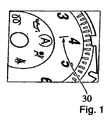
添付の図面の図3に示されるように、例えば回転数カウンターまたは回転速度計のための、ディスプレイエレメント1は、ダイアル2からなり、それは図3からなる。本発明によると、ディスプレイエレメント1は、3次元形状に形成される。ディスプレイエレメントはまた、装飾エレメント10とも呼ばれ、図4に概略的断面で描かれている。図4で見ることができないのは、装飾エレメント10またはディスプレイエレメント1が、装飾エレメント10の3次元形状を形成するために異なる平面を有する部分または領域からなることである。これは、装飾エレメント10のいくつかの部分がその他の領域または部分よりも熱成形プロセス中に(装飾エレメントの寧ろ平坦な状態から)より大きな程度まで変形されていることが関与する。熱成形プロセス中により少なく変形される装飾エレメント10の部分または領域は、折れ目30を作り出す傾向を有し、それは図1および2に概略的に描かれている。 As shown in FIG. 3 of the accompanying drawings, the
本発明によると、装飾エレメント10は、第1の面11と第2の面12を有する。第1の面11は、第2の面12と反対側にある。第1の面11上には、16で指し示された印刷された領域があっても良い。 According to the invention, the
本発明によると、折れ目30は、熱成形作業中に変形されない部分または領域が、熱成形プロセス中により多く変形されるその他の領域よりも少なく加熱される時に、防止または少なくとも削減され得る。 According to the present invention, folds 30 can be prevented or at least reduced when portions or areas that are not deformed during the thermoforming operation are heated less than other areas that are deformed more during the thermoforming process.
本発明によると、(装飾エレメントの材料の可塑化温度、例えば、160℃または165℃、を少なくとも部分的に達成するために熱成形プロセスの第1のステップ中に)接触によって装飾エレメント10の材料を加熱するために加熱されたプレートを使うことにより、装飾エレメント10の材料への(加熱されたプレート(図には描かれていない)からの)熱の配送は、装飾エレメント10の第2の面12(つまり、加熱されたプレートにタッチする面)上に印刷されたエレメンツ14を作成することによって制御されることができる。印刷されたエレメンツ14は、例えば、インクを使ってかまたは装飾エレメント10の材料上に印刷されることができる別の材料を使って作成された印刷スポットである。 According to the invention, the material of the
印刷されたエレメンツ14の領域(または位置)は、図4に13で指し示され、印刷されたエレメンツ14が無い領域(または位置)と対照的であり、この領域(または位置)は15で指し示されている。印刷されたエレメンツ14の領域(または位置)13は、領域15よりもより大きなレベルの粗さを有する実効的表面を有する。このようにして、加熱されたプレートから装飾エレメント10の材料への熱の配送は、印刷されたエレメンツ14が有る領域(または位置)で削減される。 The region (or position) of the printed
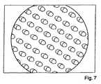
本発明の文脈では、印刷されたエレメンツ14はまた、スポットとも呼ばれる。図7の例は、約0.25ミリメートル×0.2ミリメートルの印刷されたエレメンツ14(またはスポット14)のサイズ(装飾エレメント10の主要な広がり平面と平行な広がり)をもち、約12マイクロメートルの厚さをもった、本発明による印刷されたエレメンツ14の描写である。印刷されたエレメンツ14は、描かれた例では、装飾エレメント10の第2の面12上の2次元中に、線形なやり方で(つまり、直線中に一つ一つが次々と)配列されている。印刷されたエレメンツ14は、描かれた例では、0.1ミリメートルと0.2ミリメートルの間で、直線に沿って間隔を空けられている。 In the context of the present invention, the printed
印刷されたエレメンツ14のそのような実施形態では、印刷されたエレメンツ14は、装飾エレメント10との接触による加熱中の熱の配送を制御するように、小さくでお互いと十分に近い。 In such an embodiment of the printed
[参照番号のリスト]
1 ディスプレイエレメント
2 ダイアル
3 数字
4 平らな部分または領域
5 隔離領域
10 装飾エレメント
11 装飾エレメントの第1の面
12 装飾エレメントの第2の面
13 印刷されたエレメンツの領域/位置
14 印刷されたエレメンツ
15 印刷されたエレメンツの無い領域/位置
30 折れ目[List of reference numbers]
DESCRIPTION OF
Claims (10)
Translated fromJapanese第1の面(11)はインストルメントパネルのユーザに視認可能であり、第2の面(12)は第1の面(11)と反対側に設けられており、
装飾エレメント(10)は、第2の面(12)上の多数の印刷されたエレメンツ(14)を含み、
印刷されたエレメンツ(14)の露出した領域と第2の面(12)の露出した領域によって形成された表面が、印刷されたエレメンツ(14)が無い位置に対して印刷されたエレメンツ(14)の位置において持ち上げられた部分を含み、持ち上げられた部分は、装飾エレメント(10)の熱成形プロセスにおける装飾エレメント(10)の材料への熱の配送を削減する、
ことを特徴とする装飾エレメント(10)。A decorative element (10), particularly for use in connection with an automotive instrument panel, the decorative element (10) havinga thermoformed three-dimensional shape, the decorative element (10) being a first Including a surface (11) and a second surface (12);
The first surface (11) is visible to the user of the instrument panel, and the second surface (12) is provided on the opposite side of the first surface (11),
The decorative element (10) includes a number of printed elements (14) on the second side (12),
An element (14) in which the surface formed by the exposed area of the printed elements (14) and the exposed area of the second surface (12) is printed at a position where there is no printed elements (14). The raised portion reduces the delivery of heat to the material of the decorative element (10) in the thermoforming process of the decorative element (10),
A decorative element (10) characterized in that.
装飾エレメント(10)は自動車のインストルメントパネルと接続されての使用のためのものであり、装飾エレメント(10)は3次元形状を有し、
装飾エレメント(10)は第1の面(11)と第2の面(12)を含み、
第1の面(11)はインストルメントパネルのユーザに視認可能であり、第2の面(12)は第1の面(11)と反対側に設けられており、装飾エレメント(10)の3次元形状は装飾エレメント(10)の熱成形のプロセス中に得られており、
装飾エレメント(10)の熱成形のプロセスは、装飾エレメント(10)の平らな状態での接触によって装飾エレメント(10)を加熱する第1のステップを含み、
装飾エレメント(10)の熱成形のプロセスは、装飾エレメント(10)の3次元形状を得るために装飾エレメント(10)を成形する第2のステップを含み、
装飾エレメント(10)は、第2の面上の多数の印刷されたエレメンツ(14)を含み、
印刷されたエレメンツ(14)の露出した領域と第2の面(12)の露出した領域によって形成された表面が、印刷されたエレメンツ(14)が無い位置に対して印刷されたエレメンツ(14)の位置において持ち上げられた部分を含み、持ち上げられた部分は、装飾エレメント(10)の熱成形プロセスにおける装飾エレメント(10)の材料への熱の配送を削減する、
ことを特徴とする方法。A method for manufacturing a decorative element (10), comprising:
The decorative element (10) is for use in connection with an automotive instrument panel, the decorative element (10) has a three-dimensional shape,
The decorative element (10) includes a first surface (11) and a second surface (12),
The first surface (11) is visible to the user of the instrument panel, the second surface (12) is provided on the opposite side of the first surface (11), and the decorative element (10) 3 The dimensional shape is obtained during the thermoforming process of the decorative element (10),
The process of thermoforming the decorative element (10) includes a first step of heating the decorative element (10) by the flat contact of the decorative element (10);
The process of thermoforming the decorative element (10) includes a second step of forming the decorative element (10) to obtain a three-dimensional shape of the decorative element (10);
The decorative element (10) includes a number of printed elements (14) on the second side;
An element (14) in which the surface formed by the exposed area of the printed elements (14) and the exposed area of the second surface (12) is printed at a position where there is no printed elements (14). The raised portion reduces the delivery of heat to the material of the decorative element (10) in the thermoforming process of the decorative element (10),
A method characterized by that.
Applications Claiming Priority (5)
| Application Number | Priority Date | Filing Date | Title |
|---|---|---|---|
| DE102011012934 | 2011-03-03 | ||
| DE102011012934.0 | 2011-03-03 | ||
| FR11/02001 | 2011-06-28 | ||
| FR1102001AFR2972147A1 (en) | 2011-03-03 | 2011-06-28 | DECORATIVE ELEMENT, DASHBOARD AND METHOD FOR MANUFACTURING A DECORATIVE ELEMENT |
| PCT/EP2012/000862WO2012116805A1 (en) | 2011-03-03 | 2012-02-28 | Decorative element, instrument panel and method of manufacturing a decorative element |
Publications (2)
| Publication Number | Publication Date |
|---|---|
| JP2014514195A JP2014514195A (en) | 2014-06-19 |
| JP6038052B2true JP6038052B2 (en) | 2016-12-07 |
Family
ID=46690881
Family Applications (1)
| Application Number | Title | Priority Date | Filing Date |
|---|---|---|---|
| JP2013555788AExpired - Fee RelatedJP6038052B2 (en) | 2011-03-03 | 2012-02-28 | Decorative element, instrument panel, and method of manufacturing decorative element |
Country Status (5)
| Country | Link |
|---|---|
| US (1) | US20140062116A1 (en) |
| EP (1) | EP2681068B1 (en) |
| JP (1) | JP6038052B2 (en) |
| FR (1) | FR2972147A1 (en) |
| WO (1) | WO2012116805A1 (en) |
Families Citing this family (1)
| Publication number | Priority date | Publication date | Assignee | Title |
|---|---|---|---|---|
| ES2922028A1 (en) | 2021-02-23 | 2022-09-06 | Srg Global Liria S L | A MULTI-SHOTS INJECTION MOLDING METHOD OF A DECORATIVE PIECE FOR THE FRONT OF A VEHICLE AND A MULTI-SHOTS INJECTION MOLDED DECORATIVE PART FOR THE FRONT OF A VEHICLE (Machine-translation by Google Translate, not legally binding) |
Family Cites Families (6)
| Publication number | Priority date | Publication date | Assignee | Title |
|---|---|---|---|---|
| JPH10300532A (en)* | 1997-04-25 | 1998-11-13 | Nippon Seiki Co Ltd | Display plate |
| ATE372227T1 (en)* | 2002-08-03 | 2007-09-15 | Mcgavigan John Ltd | DISPLAY DEVICES HAVING A SHEET-LIKE MOLDING |
| JP2006281707A (en)* | 2005-04-04 | 2006-10-19 | Honda Motor Co Ltd | Molding method of resin molded products |
| JP4808536B2 (en)* | 2006-04-07 | 2011-11-02 | 日産自動車株式会社 | Skin material, interior parts, and heat dissipation body structure |
| KR101290584B1 (en)* | 2006-06-29 | 2013-07-30 | 엘지디스플레이 주식회사 | Direct type backlight unit and method for forming diffuser in the direct type backlight unit |
| JP2009209795A (en)* | 2008-03-04 | 2009-09-17 | Ishikawa Gasket Co Ltd | Insulator for internal combustion engine |
- 2011
- 2011-06-28FRFR1102001Apatent/FR2972147A1/enactivePending
- 2012
- 2012-02-28WOPCT/EP2012/000862patent/WO2012116805A1/enactiveApplication Filing
- 2012-02-28USUS14/002,251patent/US20140062116A1/ennot_activeAbandoned
- 2012-02-28EPEP12710025.3Apatent/EP2681068B1/ennot_activeNot-in-force
- 2012-02-28JPJP2013555788Apatent/JP6038052B2/ennot_activeExpired - Fee Related
Also Published As
| Publication number | Publication date |
|---|---|
| WO2012116805A1 (en) | 2012-09-07 |
| JP2014514195A (en) | 2014-06-19 |
| FR2972147A1 (en) | 2012-09-07 |
| US20140062116A1 (en) | 2014-03-06 |
| EP2681068A1 (en) | 2014-01-08 |
| EP2681068B1 (en) | 2016-02-24 |
Similar Documents
| Publication | Publication Date | Title |
|---|---|---|
| TWI556990B (en) | A 3d printed decorative film and products made thereof | |
| JP6271135B2 (en) | Light-transmitting artificial leather sheet and synthetic resin molded product using the same | |
| EP2537816A1 (en) | Glass manufacturing method and mould for glass manufacture | |
| JP5288151B2 (en) | Synthetic resin molded product surface decoration method and surface decorated synthetic resin molded product | |
| JP2009297954A (en) | Decoration panel, display device, and manufacturing process of decoration panel | |
| JP6240656B2 (en) | Seat seat fabric and production method of seat seat fabric | |
| CN103799675A (en) | Method for manufacturing artificial nails and artificial nails manufactured by the method | |
| JP6038052B2 (en) | Decorative element, instrument panel, and method of manufacturing decorative element | |
| JP5327509B2 (en) | Decorative synthetic resin molded product | |
| JP2003159900A (en) | Decorative molded product and method for manufacturing the molded product | |
| AU2010292037B2 (en) | Laminating material and method of manufacturing | |
| EP1488918B1 (en) | Decorative sheet, shaped product, automobile, and method for producing shaped product | |
| CN116568524B (en) | Method for manufacturing a decorative panel and related decorative panel | |
| CN102169654A (en) | Double-face printing component and printing method thereof, and character board using the double-face printing component | |
| CN117098674B (en) | Decorative film for insert molding, method for producing same, and method for producing resin molded article | |
| EP3162534B1 (en) | Method for producing a plastic surface with an integrated decoration | |
| JP2004250568A (en) | Adhesive sheet | |
| US20070009713A1 (en) | Scored applique for instrument panels | |
| JP7720037B2 (en) | Decorative skin material, decorative member, display system, method for manufacturing decorative skin material, and method for manufacturing decorative member | |
| CN204801373U (en) | Decorate dull polish optics hard coating film that can print with surface in mould | |
| JP7506942B1 (en) | Thermoforming method and apparatus, thermoformed product | |
| JP2020040316A (en) | Manufacturing method of fine protrusion | |
| WO2025022703A1 (en) | Decorative panel and manufacturing method | |
| JP6588387B2 (en) | Decorative panel, vehicle interior equipped with the same, and method for producing decorative panel | |
| JP6057465B2 (en) | Manufacturing method of resin molded products |
Legal Events
| Date | Code | Title | Description |
|---|---|---|---|
| A131 | Notification of reasons for refusal | Free format text:JAPANESE INTERMEDIATE CODE: A131 Effective date:20140930 | |
| A521 | Request for written amendment filed | Free format text:JAPANESE INTERMEDIATE CODE: A523 Effective date:20141226 | |
| A131 | Notification of reasons for refusal | Free format text:JAPANESE INTERMEDIATE CODE: A131 Effective date:20150609 | |
| A521 | Request for written amendment filed | Free format text:JAPANESE INTERMEDIATE CODE: A523 Effective date:20150908 | |
| A131 | Notification of reasons for refusal | Free format text:JAPANESE INTERMEDIATE CODE: A131 Effective date:20160223 | |
| A521 | Request for written amendment filed | Free format text:JAPANESE INTERMEDIATE CODE: A523 Effective date:20160513 | |
| TRDD | Decision of grant or rejection written | ||
| A01 | Written decision to grant a patent or to grant a registration (utility model) | Free format text:JAPANESE INTERMEDIATE CODE: A01 Effective date:20161011 | |
| A61 | First payment of annual fees (during grant procedure) | Free format text:JAPANESE INTERMEDIATE CODE: A61 Effective date:20161101 | |
| R150 | Certificate of patent or registration of utility model | Ref document number:6038052 Country of ref document:JP Free format text:JAPANESE INTERMEDIATE CODE: R150 | |
| LAPS | Cancellation because of no payment of annual fees |