JP6037039B2 - Tactile presentation device - Google Patents
Tactile presentation deviceDownload PDFInfo
- Publication number
- JP6037039B2 JP6037039B2JP2015541581AJP2015541581AJP6037039B2JP 6037039 B2JP6037039 B2JP 6037039B2JP 2015541581 AJP2015541581 AJP 2015541581AJP 2015541581 AJP2015541581 AJP 2015541581AJP 6037039 B2JP6037039 B2JP 6037039B2
- Authority
- JP
- Japan
- Prior art keywords
- diaphragm
- film
- presentation device
- film member
- tactile sense
- Prior art date
- Legal status (The legal status is an assumption and is not a legal conclusion. Google has not performed a legal analysis and makes no representation as to the accuracy of the status listed.)
- Active
Links
Images


Classifications
- G—PHYSICS
- G06—COMPUTING OR CALCULATING; COUNTING
- G06F—ELECTRIC DIGITAL DATA PROCESSING
- G06F3/00—Input arrangements for transferring data to be processed into a form capable of being handled by the computer; Output arrangements for transferring data from processing unit to output unit, e.g. interface arrangements
- G06F3/01—Input arrangements or combined input and output arrangements for interaction between user and computer
- G06F3/016—Input arrangements with force or tactile feedback as computer generated output to the user
- G—PHYSICS
- G06—COMPUTING OR CALCULATING; COUNTING
- G06F—ELECTRIC DIGITAL DATA PROCESSING
- G06F3/00—Input arrangements for transferring data to be processed into a form capable of being handled by the computer; Output arrangements for transferring data from processing unit to output unit, e.g. interface arrangements
- G06F3/01—Input arrangements or combined input and output arrangements for interaction between user and computer
- G06F3/02—Input arrangements using manually operated switches, e.g. using keyboards or dials
- G06F3/0202—Constructional details or processes of manufacture of the input device
- G06F3/0219—Special purpose keyboards
- G—PHYSICS
- G06—COMPUTING OR CALCULATING; COUNTING
- G06F—ELECTRIC DIGITAL DATA PROCESSING
- G06F3/00—Input arrangements for transferring data to be processed into a form capable of being handled by the computer; Output arrangements for transferring data from processing unit to output unit, e.g. interface arrangements
- G06F3/01—Input arrangements or combined input and output arrangements for interaction between user and computer
- G06F3/03—Arrangements for converting the position or the displacement of a member into a coded form
- G06F3/041—Digitisers, e.g. for touch screens or touch pads, characterised by the transducing means
- G06F3/0416—Control or interface arrangements specially adapted for digitisers
- G—PHYSICS
- G06—COMPUTING OR CALCULATING; COUNTING
- G06F—ELECTRIC DIGITAL DATA PROCESSING
- G06F3/00—Input arrangements for transferring data to be processed into a form capable of being handled by the computer; Output arrangements for transferring data from processing unit to output unit, e.g. interface arrangements
- G06F3/01—Input arrangements or combined input and output arrangements for interaction between user and computer
- G06F3/048—Interaction techniques based on graphical user interfaces [GUI]
- G06F3/0487—Interaction techniques based on graphical user interfaces [GUI] using specific features provided by the input device, e.g. functions controlled by the rotation of a mouse with dual sensing arrangements, or of the nature of the input device, e.g. tap gestures based on pressure sensed by a digitiser
- G06F3/0488—Interaction techniques based on graphical user interfaces [GUI] using specific features provided by the input device, e.g. functions controlled by the rotation of a mouse with dual sensing arrangements, or of the nature of the input device, e.g. tap gestures based on pressure sensed by a digitiser using a touch-screen or digitiser, e.g. input of commands through traced gestures
- G06F3/04886—Interaction techniques based on graphical user interfaces [GUI] using specific features provided by the input device, e.g. functions controlled by the rotation of a mouse with dual sensing arrangements, or of the nature of the input device, e.g. tap gestures based on pressure sensed by a digitiser using a touch-screen or digitiser, e.g. input of commands through traced gestures by partitioning the display area of the touch-screen or the surface of the digitising tablet into independently controllable areas, e.g. virtual keyboards or menus
- H—ELECTRICITY
- H04—ELECTRIC COMMUNICATION TECHNIQUE
- H04R—LOUDSPEAKERS, MICROPHONES, GRAMOPHONE PICK-UPS OR LIKE ACOUSTIC ELECTROMECHANICAL TRANSDUCERS; DEAF-AID SETS; PUBLIC ADDRESS SYSTEMS
- H04R17/00—Piezoelectric transducers; Electrostrictive transducers
- H04R17/005—Piezoelectric transducers; Electrostrictive transducers using a piezoelectric polymer
- H—ELECTRICITY
- H04—ELECTRIC COMMUNICATION TECHNIQUE
- H04R—LOUDSPEAKERS, MICROPHONES, GRAMOPHONE PICK-UPS OR LIKE ACOUSTIC ELECTROMECHANICAL TRANSDUCERS; DEAF-AID SETS; PUBLIC ADDRESS SYSTEMS
- H04R17/00—Piezoelectric transducers; Electrostrictive transducers
- H04R17/02—Microphones
- H04R17/025—Microphones using a piezoelectric polymer
- H—ELECTRICITY
- H04—ELECTRIC COMMUNICATION TECHNIQUE
- H04R—LOUDSPEAKERS, MICROPHONES, GRAMOPHONE PICK-UPS OR LIKE ACOUSTIC ELECTROMECHANICAL TRANSDUCERS; DEAF-AID SETS; PUBLIC ADDRESS SYSTEMS
- H04R7/00—Diaphragms for electromechanical transducers; Cones
- H—ELECTRICITY
- H04—ELECTRIC COMMUNICATION TECHNIQUE
- H04R—LOUDSPEAKERS, MICROPHONES, GRAMOPHONE PICK-UPS OR LIKE ACOUSTIC ELECTROMECHANICAL TRANSDUCERS; DEAF-AID SETS; PUBLIC ADDRESS SYSTEMS
- H04R7/00—Diaphragms for electromechanical transducers; Cones
- H04R7/02—Diaphragms for electromechanical transducers; Cones characterised by the construction
- H04R7/04—Plane diaphragms
- H04R7/06—Plane diaphragms comprising a plurality of sections or layers
- H04R7/10—Plane diaphragms comprising a plurality of sections or layers comprising superposed layers in contact
- H—ELECTRICITY
- H04—ELECTRIC COMMUNICATION TECHNIQUE
- H04R—LOUDSPEAKERS, MICROPHONES, GRAMOPHONE PICK-UPS OR LIKE ACOUSTIC ELECTROMECHANICAL TRANSDUCERS; DEAF-AID SETS; PUBLIC ADDRESS SYSTEMS
- H04R7/00—Diaphragms for electromechanical transducers; Cones
- H04R7/16—Mounting or tensioning of diaphragms or cones
- H04R7/18—Mounting or tensioning of diaphragms or cones at the periphery
- H—ELECTRICITY
- H10—SEMICONDUCTOR DEVICES; ELECTRIC SOLID-STATE DEVICES NOT OTHERWISE PROVIDED FOR
- H10N—ELECTRIC SOLID-STATE DEVICES NOT OTHERWISE PROVIDED FOR
- H10N30/00—Piezoelectric or electrostrictive devices
- H10N30/20—Piezoelectric or electrostrictive devices with electrical input and mechanical output, e.g. functioning as actuators or vibrators
- H10N30/206—Piezoelectric or electrostrictive devices with electrical input and mechanical output, e.g. functioning as actuators or vibrators using only longitudinal or thickness displacement, e.g. d33 or d31 type devices
- G—PHYSICS
- G06—COMPUTING OR CALCULATING; COUNTING
- G06F—ELECTRIC DIGITAL DATA PROCESSING
- G06F2203/00—Indexing scheme relating to G06F3/00 - G06F3/048
- G06F2203/041—Indexing scheme relating to G06F3/041 - G06F3/045
- G06F2203/04102—Flexible digitiser, i.e. constructional details for allowing the whole digitising part of a device to be flexed or rolled like a sheet of paper
- G—PHYSICS
- G06—COMPUTING OR CALCULATING; COUNTING
- G06F—ELECTRIC DIGITAL DATA PROCESSING
- G06F2203/00—Indexing scheme relating to G06F3/00 - G06F3/048
- G06F2203/041—Indexing scheme relating to G06F3/041 - G06F3/045
- G06F2203/04103—Manufacturing, i.e. details related to manufacturing processes specially suited for touch sensitive devices
- H—ELECTRICITY
- H04—ELECTRIC COMMUNICATION TECHNIQUE
- H04R—LOUDSPEAKERS, MICROPHONES, GRAMOPHONE PICK-UPS OR LIKE ACOUSTIC ELECTROMECHANICAL TRANSDUCERS; DEAF-AID SETS; PUBLIC ADDRESS SYSTEMS
- H04R17/00—Piezoelectric transducers; Electrostrictive transducers
- H04R17/04—Gramophone pick-ups using a stylus; Recorders using a stylus
- H—ELECTRICITY
- H04—ELECTRIC COMMUNICATION TECHNIQUE
- H04R—LOUDSPEAKERS, MICROPHONES, GRAMOPHONE PICK-UPS OR LIKE ACOUSTIC ELECTROMECHANICAL TRANSDUCERS; DEAF-AID SETS; PUBLIC ADDRESS SYSTEMS
- H04R2307/00—Details of diaphragms or cones for electromechanical transducers, their suspension or their manufacture covered by H04R7/00 or H04R31/003, not provided for in any of its subgroups
- H04R2307/025—Diaphragms comprising polymeric materials
- H—ELECTRICITY
- H04—ELECTRIC COMMUNICATION TECHNIQUE
- H04R—LOUDSPEAKERS, MICROPHONES, GRAMOPHONE PICK-UPS OR LIKE ACOUSTIC ELECTROMECHANICAL TRANSDUCERS; DEAF-AID SETS; PUBLIC ADDRESS SYSTEMS
- H04R2499/00—Aspects covered by H04R or H04S not otherwise provided for in their subgroups
- H04R2499/10—General applications
- H04R2499/15—Transducers incorporated in visual displaying devices, e.g. televisions, computer displays, laptops
- H—ELECTRICITY
- H04—ELECTRIC COMMUNICATION TECHNIQUE
- H04R—LOUDSPEAKERS, MICROPHONES, GRAMOPHONE PICK-UPS OR LIKE ACOUSTIC ELECTROMECHANICAL TRANSDUCERS; DEAF-AID SETS; PUBLIC ADDRESS SYSTEMS
- H04R7/00—Diaphragms for electromechanical transducers; Cones
- H04R7/02—Diaphragms for electromechanical transducers; Cones characterised by the construction
- H04R7/04—Plane diaphragms
- H04R7/045—Plane diaphragms using the distributed mode principle, i.e. whereby the acoustic radiation is emanated from uniformly distributed free bending wave vibration induced in a stiff panel and not from pistonic motion
Landscapes
- Engineering & Computer Science (AREA)
- General Engineering & Computer Science (AREA)
- Theoretical Computer Science (AREA)
- Physics & Mathematics (AREA)
- Human Computer Interaction (AREA)
- General Physics & Mathematics (AREA)
- Acoustics & Sound (AREA)
- Signal Processing (AREA)
- Multimedia (AREA)
- User Interface Of Digital Computer (AREA)
- Electronic Switches (AREA)
Description
Translated fromJapanese本発明は、利用者に振動を伝えることで触覚フィードバックを与える触覚提示装置に関する。 The present invention relates to a haptic presentation device that provides haptic feedback by transmitting vibration to a user.
近年、タッチパネル式のキーボード等において、利用者がキーをタッチした時に振動を伝えることで触覚フィードバックを与え、キーを「押した」と感じさせる触覚提示装置が提案されている。 In recent years, a touch-sensitive keyboard or the like has been proposed that provides tactile feedback by transmitting vibrations when a user touches a key to feel the key “pressed”.
例えば、特許文献1には、圧電セラミックス等からなる圧電バイモルフ素子の両端を低弾性体で保持し、当該圧電バイモルフの中央に被振動材を接続した構造が記載されている。特許文献1の構造では、圧電バイモルフ素子に交流信号を入力して振動させることにより、接続された被振動材を介して利用者に振動を伝える。 For example, Patent Document 1 describes a structure in which both ends of a piezoelectric bimorph element made of piezoelectric ceramics or the like are held by a low elastic body, and a vibrating material is connected to the center of the piezoelectric bimorph. In the structure of Patent Document 1, vibration is transmitted to a user through a connected vibration-receiving material by inputting an AC signal to the piezoelectric bimorph element and causing it to vibrate.
しかし、圧電セラミックスは割れやすいという課題がある。一方で、電圧を加えることで面方向に変形するフィルム部材(例えば圧電性樹脂)のような割れにくいものは、振動を伝える力が弱く、触覚提示装置に用いることが難しい。 However, there is a problem that piezoelectric ceramics are easily broken. On the other hand, a film member (for example, a piezoelectric resin) that is difficult to break, such as a film member that deforms in a plane direction when a voltage is applied, has a weak force to transmit vibration and is difficult to use for a tactile sense presentation device.
そこで、本発明の目的は、電圧を加えることで面方向に変形するフィルム部材を用いた場合であってもある程度強い振動を伝えることができる触覚提示装置を提供することにある。 Therefore, an object of the present invention is to provide a tactile sensation presentation apparatus that can transmit a strong vibration to some extent even when a film member that deforms in a plane direction by applying a voltage is used.
この発明の触覚提示装置は、電圧を加えることで面方向に変形するフィルム部材と、曲げ応力が発生する状態で前記フィルム部材に固定された平板状の振動板と、タッチ操作を検出するタッチ検出部と、前記タッチ検出部がタッチ操作を検出したときに、前記フィルム部材に駆動信号を印加する駆動部と、を備えたことを特徴とする。 The tactile sense presentation device according to the present invention includes a film member that deforms in a plane direction when a voltage is applied, a flat diaphragm fixed to the film member in a state where bending stress is generated, and touch detection that detects a touch operation. And a drive unit that applies a drive signal to the film member when the touch detection unit detects a touch operation.
このような触覚提示装置では、ユーザがタッチ操作を行うと、フィルム部材に駆動信号が印加され、当該フィルム部材が伸縮する。振動板は、フィルム部材の伸縮により、主面に直交する方向に振動する。振動板には、曲げ応力が発生しているため、フィルム部材の伸縮に対して効率的に振動させることができる。したがって、本発明の触覚提示装置は、電圧を加えることで面方向に変形するフィルム部材を用いた場合であってもある程度強い振動を伝えることができる。 In such a tactile sense presentation device, when the user performs a touch operation, a drive signal is applied to the film member, and the film member expands and contracts. The diaphragm vibrates in a direction orthogonal to the main surface by expansion and contraction of the film member. Since the bending stress is generated in the diaphragm, it can be efficiently vibrated with respect to the expansion and contraction of the film member. Therefore, the tactile sense presentation device of the present invention can transmit a strong vibration to some extent even when a film member that deforms in a plane direction by applying a voltage is used.
なお、フィルム部材は、圧電性樹脂からなる圧電フィルムのみからなるものであってもよいが、当該圧電フィルムを主面に装着した平板状のエキサイタフィルムからなる態様であってもよい。また、「電圧を加えることで面方向に変形するフィルム部材」は、圧電フィルムに限るものではない。「電圧を加えることで面方向に変形するフィルム部材」は、例えば電歪フィルム、エレクトレットフィルム、コンポジットフィルム、または電気活性フィルム等がある。電気活性フィルムとは、電気的駆動によって応力を発生するフィルム部材、または電気的駆動によって変形して変位を発生するフィルム部材である。具体的には、電歪フィルム、コンポジット材料(圧電セラミックスを樹脂モールドした材料)、電気駆動型エラストマー、または液晶エラストマー等がある。 In addition, although a film member may consist only of a piezoelectric film which consists of piezoelectric resin, the aspect which consists of a flat exciter film which mounted | worn the said piezoelectric film to the main surface may be sufficient. Further, the “film member that is deformed in the plane direction by applying a voltage” is not limited to the piezoelectric film. Examples of the “film member that deforms in a plane direction when a voltage is applied” include an electrostrictive film, an electret film, a composite film, and an electroactive film. An electroactive film is a film member that generates stress by electrical driving, or a film member that deforms and generates displacement by electrical driving. Specifically, there are an electrostrictive film, a composite material (a material obtained by resin-molding piezoelectric ceramics), an electrically driven elastomer, or a liquid crystal elastomer.
また、タッチ検出部は、振動板に対するタッチ操作を検出する態様であってもよいし、振動板に装着されるタッチパネルに対するタッチを検出する態様であってもよい。 Moreover, the aspect which detects the touch operation with respect to a diaphragm may be sufficient as a touch detection part, and the aspect which detects the touch with respect to the touchscreen with which a diaphragm is mounted | worn may be sufficient.
また、振動板は、フィルム部材の主面に対して直交する方向に湾曲された状態でフィルム部材に固定されることにより曲げ応力を発生させる態様でもよいし、フィルム部材に固定されていない状態では平板面が湾曲した形状であり、湾曲した平板面が平坦になるようにフィルム部材に固定されることにより曲げ応力を発生させる態様であってもよい。 Moreover, the aspect which generate | occur | produces a bending stress by fixing to a film member in the state curved in the direction orthogonal to the main surface of a film member may be sufficient as a diaphragm, and in the state which is not fixed to a film member The flat plate surface may have a curved shape, and a bending stress may be generated by being fixed to the film member so that the curved flat plate surface is flat.
また、フィルム部材は、1つに限らず、複数のフィルム部材に分割されている態様とすることも可能である。 In addition, the number of film members is not limited to one, and a mode in which the film members are divided into a plurality of film members is also possible.
また、圧電性樹脂は、ポリフッ化ビニリデンを材料とすることもできるし、キラル高分子を材料とすることもできる。特に、キラル高分子がポリ乳酸である場合、他の構成とともに透光性を有する材質とすることで、正面視した略全面が高い透光性を有する触覚提示装置を実現することができる。 The piezoelectric resin can be made of polyvinylidene fluoride or a chiral polymer. In particular, when the chiral polymer is polylactic acid, a tactile sensation presentation device that has a high translucency when viewed from the front can be realized by using a material having translucency together with other components.
この発明によれば、圧電性樹脂を用いた場合であってもある程度強い振動を伝えることができる。 According to the present invention, even if a piezoelectric resin is used, a strong vibration can be transmitted to some extent.
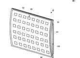
図1は、第1の実施形態に係る触覚提示装置10の外観斜視図である。図2(A)は、触覚提示装置10の正面図であり、図2(B)は、側面図である。 FIG. 1 is an external perspective view of a
触覚提示装置10は、圧電フィルム20、エキサイタフィルム30、振動板40、およびタッチパネル50を備えている。触覚提示装置10は、いわゆるキーボードであり、平板状のタッチパネル50には、キー配列に対応した位置に複数のタッチセンサ80が設けられている。タッチセンサ80が本発明のタッチ検出部に相当する。タッチセンサ80は、ユーザのタッチ操作を検出する機能であればどの様な方式であってもよく、メンブレン式、静電容量式、圧電フィルム式、等の様々な方式を用いることができる。 The
タッチパネル50は、平板状の振動板40の一方の主面(正面)に装着されている。振動板40は、平面視して矩形状である。振動板40は、他方の主面の(背面)において短手方向の両端がエキサイタフィルム30に固定されている。振動板40は、例えばアクリル樹脂PMMAで構成されている。なお、振動板40は、金属板、PET、ポリカーボネイト(PC)、ポリメタクリル酸メチル樹脂(PMMA)、ガラス等の他の材料を用いてもよい。 The
なお、タッチパネル50は、必須ではない。例えば、振動板40の正面において、キー配列に対応した位置に複数のタッチセンサ80を設ける態様とすることも可能である。 Note that the
エキサイタフィルム30は、振動板40と同様に平面視して矩形状である。エキサイタフィルム30は、例えばポリエチレンテレフタレート(PET)で構成されている。なお、エキサイタフィルム30は、ポリエチレンナノフタレート(PEN)、ポリエチレン(PE)、ポリプロピレン(PP)、ポリ塩化ビニル(PVC)等の他の材料を用いてもよい。また、圧電フィルム20と同じ材料であってもよい。エキサイタフィルム30の厚みは、伸縮性を阻害しないような厚み(例えば0.02〜0.5mm程度)が望ましい。 The
エキサイタフィルム30は、一方の主面に圧電フィルム20が装着されている。この例では、圧電フィルム20は、エキサイタフィルム30の主面のうち、振動板40が装着された側と反対側の主面に装着されているが、振動板40が装着された側の主面に装着されてもよい。 The
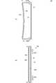
図3の触覚提示装置10の部分拡大側面図に示すように、圧電フィルム20は、平面視して矩形状のベースフィルム200と、該ベースフィルム200の対向する両主面に形成された電極201Aおよび電極201Bを備える。 As shown in the partial enlarged side view of the tactile
ベースフィルム200は、圧電性樹脂であり、例えばポリフッ化ビニリデン(PVDF)、キラル高分子、等の材料を用いる。より好ましくは、透光性の高いポリ乳酸(PLA)を用いる。特にPLLAで構成されていることが望ましい。PLAを用いる場合、他の構成も透光性の高い材料を用いることにより、正面視した略全面が高い透光性を有する触覚提示装置10を実現することができる。また、PLLAは、焦電性が無く、周囲温度の変化によって影響されない。したがって、気温の変化、電子機器の発熱、または指が接触することによる温度変化等によって振動の強さが変わらない。 The
ベースフィルム200は、PLLAで構成される場合、図2(A)に示すように、延伸方向に対して各外周辺が略45°となるように裁断することで、矩形状を形成して、圧電性を持たせる。 When the
電極201Aおよび電極201Bは、ベースフィルム200の両主面の略全面に形成されている。電極201Aおよび電極201Bは、酸化インジウムスズ(ITO)、酸化亜鉛(ZnO)、ポリチオフェンを主成分とすることが好ましい。なお、電極201Aおよび電極201Bには、銀ナノワイヤ電極を用いることも可能であるし、透光性が低くてよい使用態様であれば、アルミ蒸着電極を用いることが好ましい。電極201Aおよび電極201Bには、図示しない引き出し用の配線導体が接続されており、駆動信号が当該配線導体を介して電極201Aおよび電極201Bへ印加されるようになっている。エキサイタフィルム30側に配置される電極201Aは、接着層60を介してエキサイタフィルム30に装着される。 The
図4に示すように、タッチパネル50に設けられたタッチセンサ80をユーザがタッチすると、駆動部81が圧電フィルム20の電極201Aおよび電極201Bに駆動信号を印加する。これにより圧電フィルム20が伸縮する。 As shown in FIG. 4, when the user touches the
図1および図2(B)に示すように、振動板40は、エキサイタフィルム30の存在する側(振動板40の背面側)に対して反対側(振動板40の正面側)に湾曲して突出する形状となるように、エキサイタフィルム30へ固定されている。この構成により、振動板40とエキサイタフィルム30との間には、中空領域100が形成される。そして、この振動板40のある側が触覚提示装置10の正面側となり、エキサイタフィルム30がある側が触覚提示装置10の背面側となる。 As shown in FIG. 1 and FIG. 2B, the
ただし、本実施形態において、振動板40の湾曲状態は、説明のために誇張して記載しており、実際には、振動板40の主面とエキサイタフィルム30の主面は、より平行に近く、中空領域100は、できるだけ少ないほうが望ましい。 However, in the present embodiment, the curved state of the
このように、振動板40は、平板面が湾曲した状態でエキサイタフィルム30に固定されるため、図2(B)の白抜き矢印F901のように、曲げ応力が加わった状態でエキサイタフィルム30に固定される。また、エキサイタフィルム30には、図2(B)の白抜き矢印S901に示すように、エキサイタフィルム30の主面における短手方向に引張力が係った状態となる。 Thus, since the
図5は、触覚提示装置10の動作説明図であり、図5(A)は、駆動信号により圧電フィルム20が縮んだタイミングでの状態を示す。図5(B)は、駆動信号が印加されていない、または駆動信号の振幅が0の状態を示す。図5(C)は、駆動信号により圧電フィルム20が伸びたタイミングでの状態を示す。 FIG. 5 is an operation explanatory diagram of the tactile
駆動部81が、圧電フィルム20に駆動信号を印加し、圧電フィルム20の第一方向の電界を印加すると、図5(A)の矢印S911に示すように、圧電フィルム20は、振動板40およびエキサイタフィルム30の固定端に直交する方向に沿って収縮する。圧電フィルム20は、エキサイタフィルム30の背面に装着されているため、圧電フィルム20の収縮にともなってエキサイタフィルム30の背面側が収縮する。このとき、エキサイタフィルム30は、主面に直交する方向のうち正面側にわずかに湾曲することになる。そして、振動板40は、エキサイタフィルム30に固定されている箇所(短手方向の端部)から中央方向に引っ張られる。これにより、振動板40は、図4(A)の矢印F911に示すように、前方へより突出するように湾曲する。 When the
一方、駆動部81が、圧電フィルム20に駆動信号を印加し、上記第一方向とは逆の第二方向の電界を印加すると、図5(C)の矢印S912に示すように、圧電フィルム20は、振動板40およびエキサイタフィルム30の固定端に直交する方向に沿って伸張する。圧電フィルム20は、エキサイタフィルム30の背面に装着されているため、圧電フィルム20の収縮にともなってエキサイタフィルム30の背面側が伸張する。このとき、エキサイタフィルム30は主面に直交する方向のうち背面側にわずかに湾曲することになる。そして、振動板40は、中央方向からエキサイタフィルム30に固定されている箇所(短手方向の端部)に引っ張られる。これにより、振動板40は、図5(C)の矢印F912に示すように、前方への突出量が低下した湾曲状態となる。 On the other hand, when the
したがって、振動板40は、駆動信号の振幅に応じて、図5(B)の状態を基準に、図5(A)の状態や図5(C)の状態に遷移して、正面方向および背面方向(振動板40主面に直交する方向)に沿って振動する。これにより、駆動信号に応じた振動が振動板40を介してタッチパネル50に伝達され、タッチパネル50をタッチしたユーザに伝達される。したがって、ユーザは、タッチパネル50のタッチセンサ80をタッチすると、振動がフィードバックされるため、キーを「押した」と感じることができる。 Therefore, the
そして、振動板40には、非動作状態で定常的な曲げ応力が与えられているため、圧電フィルム20およびエキサイタフィルム30の伸張時に振動板40に与えられる力は、当該曲げ応力と同じ方向となる。したがって、触覚提示装置10は、振動板40を効率的に振動させることができ、圧電フィルムを用いた場合であってもある程度強い振動を伝えることができる。また、モータ等による振動に比べると、触覚提示装置10を薄くすることができる。 Since a stationary bending stress is applied to the
なお、中空領域100には、シリコーンゲル等の柔らかい樹脂を充填し、エキサイタフィルム30および振動板40が振動することにより生じる音を抑制することが望ましい。 In addition, it is desirable to fill the
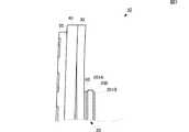
次に、第2の実施形態に係る触覚提示装置について説明する。図6は、第2の実施形態に係る触覚提示装置10Aの外観斜視図である。図7(A)は、振動板40Aを固定する前の状態を示し、図7(B)は、振動板40Aを固定した後の状態を示す構造説明図である。 Next, a tactile sense presentation device according to a second embodiment will be described. FIG. 6 is an external perspective view of a tactile
第2の実施形態に係る触覚提示装置10Aは、第1の実施形態に示した触覚提示装置10に対して、振動板40Aの主面とエキサイタフィルム30の主面とが平行になるように、振動板40Aの端部がフレーム70を介してエキサイタフィルム30に固定される点で異なる。また、この例では、圧電フィルム20は、エキサイタフィルム30の正面側に装着されている。他の構成は、触覚提示装置10と同じである。 The
振動板40Aは、第1の実施形態に示した振動板40と同じ材質であるが、図7(A)に示すように、エキサイタフィルム30に固定されていない状態では、平板面が湾曲した形状である。このような形状は、例えば、平坦な主面を有する振動板を熱処理等により屈曲させることで実現できる。 The
振動板40Aは、図7(A)の白抜き矢印St902に示すように、両端に曲げ力を加えながら、図7(B)に示すように、湾曲した平板面が平坦となるようにフレーム70を介してエキサイタフィルム30に固定する。振動板40Aは、このような状態でエキサイタフィルム30に固定されることにより、第1の実施形態と同様に曲げ応力が発生した状態となる。また、図7(B)の太矢印S902に示すように、エキサイタフィルム30は、主面に平行で振動板40を固定する両端辺に対して直交する方向の中心から固定端方向に向かって引っ張られる。 As shown in a white arrow St902 in FIG. 7A, the
このような構成であっても、上述の第1の実施形態と同様の作用効果を得ることができる。さらに、本実施形態の構成を用いれば、振動板40Aの主面を平坦に固定することができる。したがって、振動板40Aに装着するタッチパネル50Aも平坦にすることができる。 Even with such a configuration, the same operational effects as those of the first embodiment described above can be obtained. Furthermore, if the configuration of the present embodiment is used, the main surface of the
次に、第3の実施形態に係る触覚提示装置について、図を参照して説明する。図8は、第3の実施形態に係る触覚提示装置10Bを背面側から見た図である。触覚提示装置10Bは、第1の実施形態に係る触覚提示装置10に対して、圧電フィルム20が複数(この例では2つ)の圧電フィルム20Rおよび圧電フィルム20Lに分割されている点で異なる。その他の構成は、触覚提示装置10と同様である。 Next, a tactile sense presentation device according to a third embodiment will be described with reference to the drawings. FIG. 8 is a view of the tactile
この場合、圧電フィルム20Rおよび圧電フィルム20Lを、それぞれ個別に駆動させることができる。例えば、圧電フィルム20Rおよび圧電フィルム20Lに対し、逆位相の駆動信号を印加することも可能である。なお、圧電フィルムの数は、さらに多数(例えば3つ)であってもよい。複数の圧電フィルムを装着する場合、各フィルムの動作を調整することによって、タッチパネル50に設けられたタッチセンサ80の位置による振動のばらつきを小さくすることができる。 In this case, the
図9は、第4の実施形態に係る触覚提示装置10Cを背面側から見た図である。触覚提示装置10Cは、第3の実施形態に係る触覚提示装置10Bに対して、エキサイタフィルム30が複数(この例では2つ)のエキサイタフィルム30Rおよびエキサイタフィルム30Lに分割され、エキサイタフィルム30Rおよびエキサイタフィルム30Lにそれぞれ圧電フィルム20Rおよび圧電フィルム20Lが装着されている点で異なる。その他の構成は、触覚提示装置10Bと同様である。 FIG. 9 is a view of the tactile sense presentation device 10C according to the fourth embodiment as viewed from the back side. In the tactile presentation device 10C, the
この場合、エキサイタフィルム30Rおよびエキサイタフィルム30Lを、それぞれ個別に伸縮させることができる。例えば、圧電フィルム20Rおよび圧電フィルム20Lに対し、逆位相の駆動信号を印加することで、エキサイタフィルム30Rおよびエキサイタフィルム30Lをそれぞれ逆方向に変形させることができる。複数のエキサイタフィルムを装着する場合、各フィルムの動作を調整することによって、タッチパネル50に設けられたタッチセンサ80の位置による振動のばらつきを小さくすることができる。また、複数のエキサイタフィルムを装着する場合、エキサイタフィルムの非装着部の中空領域に、図示しない引き出し用の配線導体、または駆動信号を供給する回路等の部品を配置させることができるため、触覚提示装置をコンパクトにすることができる。 In this case, the
次に、図10(A)は、圧電フィルム20の変形例に係る圧電フィルム20Aの側面図である。図3に示した圧電フィルム20は、1つのベースフィルム200を電極201Aおよび電極201Bで挟む構造であったが、図10(A)に示す圧電フィルム20Aは、ベースフィルム200、電極201Aおよび電極201Bが複数積層されてなる。この例では、各ベースフィルム200を挟んで、交互に電極201Aと電極201Bとが配置されている。このように複数のベースフィルム200、電極201Aおよび電極201Bを積層することで、より伸縮性が向上することになり、強い振動を発生させることができる。 Next, FIG. 10A is a side view of a
一方、図10(B)は、変形例2に係る圧電フィルム20Bの側面図である。図10(B)に示す圧電フィルム20Bは、1つのベースフィルム200を電極201Aおよび電極201Bで挟み、かつこれらベースフィルム200、電極201Aおよび電極201Bを折り曲げて重ねることにより、積層構造を実現するものである。この場合も、より伸縮性が向上することになり、強い振動を発生させることができる。ただし、この場合、電極を折り曲げる箇所においては、導電性ペースト等を塗布して、電気的接続を補強することが好ましい。 On the other hand, FIG. 10B is a side view of the piezoelectric film 20B according to the second modification. The piezoelectric film 20B shown in FIG. 10B realizes a laminated structure by sandwiching one
なお、上述の実施形態では、フィルム部材が圧電フィルム20とエキサイタフィルム30とからなる例を示したが、エキサイタフィルム30は本発明において必須の構成ではない。例えば、図11に示すように、圧電フィルム20の電極201Aと、振動板40と、を接着層60で接続して振動板40を固定するようにしてもよい。この場合、圧電フィルム20が本発明のフィルム部材に相当する。 In the above-described embodiment, an example in which the film member is composed of the
また、圧電フィルム20と振動板40との接続態様は、図12に示すような態様も可能である。例えば、図12(A)に示すように、振動板40は、圧電フィルム20のうち電極201Aが形成されていない箇所に接続されるようにしてもよい。この場合、振動板40は、ベースフィルム200に接着層60を介して接続される。 Further, the connection mode between the
図11の例では、振動板40は、接着層60を介して電極201Aに接続されていたため、ベースフィルム200が伸縮したとき、電極201Aに機械的な負荷が発生する。一般に、電極は、蒸着等の物理的接合によって形成されるため、接着剤等による化学的接合に比べると接合の強度が低い。したがって、ベースフィルム200と電極201Aとの間が剥離する可能性があった。しかし、図12(A)の構造では、振動板40が電極201Aに接続されていないため、電極201Aには機械的な負荷が発生しない。したがって、図12(A)の構造では、電極が剥離することを防ぐことができる。また、図12(A)の構造では、振動板40が導体である場合に、ベースフィルム200を絶縁することができるため、例えば触覚提示装置を操作している際に静電気によって振動板が帯電したとしてもベースフィルム200に負荷がかからないメリットがある。 In the example of FIG. 11, the
次に、図12(B)の構造は、固定具61により振動板40と圧電フィルム20とを接続する態様である。この例では、振動板40および圧電フィルム20に貫通孔を開け、当該貫通孔にリベット形状の固定具61を挿入し、機械的に固定する態様となっている。固定具61の形状は、円柱形状であることが好ましいが、角柱形状等の他の形状であってもよい。ただし、固定具61が導体である場合、電極に接触しないように、貫通孔の周囲の電極は除去することが望ましい。図10に示したように電極が積層されている場合には、各層全ての電極について貫通孔周囲の電極を除去することが好ましい。なお、電極が積層されている場合において、例えば第1層において電極201Aを除去した場合、第2層以降は当該第1層の電極201Aと接続されて同電位となる電極側のみを除去すればよい。無論、固定具61が絶縁体である場合、電極を除去する必要はない。 Next, the structure of FIG. 12B is a mode in which the
図12(C)の構造は、振動板40に突起部41を設け、圧電フィルム20の貫通孔に当該突起部41を挿入する態様である。突起部41は、図12(B)に示した固定具61と同じ機能を有する。 The structure of FIG. 12C is a mode in which a
図13(A)の構造は、振動板40が接着層60を介してベースフィルム200に接続され、さらにベースフィルム200における貫通孔に当該接着層60が充填された態様である。この場合も、電極が剥離することを防ぐことができる。 The structure of FIG. 13A is an aspect in which the
図13(B)の構造は、振動板40および圧電フィルム20に貫通孔を開け、当該貫通孔にリベット形状の固定具61を挿入し、さらに貫通孔に接着層60が充填されるとともに振動板40が接着層60を介してベースフィルム200に接続されている態様である。この場合、振動板40と圧電フィルム20は、最も強固に固定される。 In the structure of FIG. 13B, a through hole is formed in the
図14(A)の構造は、振動板40と圧電フィルム20と挟持部材65で挟み込む態様である。挟持部材65は、厚みの薄い長方形状の板部材を2箇所90度に折り曲げてなる。挟持部材65は、折り曲げた内面で振動板40および電極201Bに接することにより、振動板40と圧電フィルム20とを挟み込むようになっている。 The structure of FIG. 14A is an aspect in which the
また、図14(B)に示すように、圧電フィルム20を折り曲げて振動板40の上面側に巻き込み、巻き込んだ圧電フィルム20を挟持部材65で挟み込むことにより振動板40と圧電フィルム20とを固定するようにしてもよい。 Further, as shown in FIG. 14B, the
さらに、図14(C)に示すように、挟持部材65の内面に接着剤62を充填し、より強固に固定するようにしてもよい。 Further, as shown in FIG. 14C, the inner surface of the sandwiching
なお、図12〜図14に示した構造は、複数の圧電フィルムを装着する場合であっても同様である。特に、複数の圧電フィルムを装着する場合、各フィルムの動作を調整することによって、タッチパネル50に設けられたタッチセンサ80の位置による振動のばらつきを小さくすることができる。また、複数の圧電フィルムを装着する場合、圧電フィルムの非装着部の中空領域に、図示しない引き出し用の配線導体、または駆動信号を供給する回路等の部品を配置させることができるため、触覚提示装置をコンパクトにすることができる。 The structure shown in FIGS. 12 to 14 is the same even when a plurality of piezoelectric films are mounted. In particular, when a plurality of piezoelectric films are mounted, the variation in vibration due to the position of the
なお、本発明における「電圧を加えることで面方向に変形するフィルム部材」は、圧電フィルムに限るものではない。「電圧を加えることで面方向に変形するフィルム部材」は、例えば電歪フィルム、エレクトレットフィルム、コンポジットフィルム、または電気活性フィルム等がある。 In the present invention, the “film member that is deformed in the plane direction when a voltage is applied” is not limited to a piezoelectric film. Examples of the “film member that deforms in a plane direction when a voltage is applied” include an electrostrictive film, an electret film, a composite film, and an electroactive film.
電気活性フィルムとは、電気的駆動によって応力を発生するフィルム部材、または電気的駆動によって変形して変位を発生するフィルム部材である。具体的には、電歪フィルム、コンポジット材料(圧電セラミックスを樹脂モールドした材料)、電気駆動型エラストマー、または液晶エラストマー等がある。 An electroactive film is a film member that generates stress by electrical driving, or a film member that deforms and generates displacement by electrical driving. Specifically, there are an electrostrictive film, a composite material (a material obtained by resin-molding piezoelectric ceramics), an electrically driven elastomer, or a liquid crystal elastomer.
また、「電圧を加えることで面方向に変形するフィルム部材」は、圧電セラミックスと、複数のエキサイタフィルムと、を用いることでも実現することができる。この場合、複数のエキサイタフィルムは、それぞれ一方の端部が圧電セラミックスに接続され、他方の端部が振動板に接続される。 Further, the “film member that is deformed in the plane direction when a voltage is applied” can also be realized by using piezoelectric ceramics and a plurality of exciter films. In this case, each of the plurality of exciter films has one end connected to the piezoelectric ceramic and the other end connected to the diaphragm.
10…触覚提示装置
20…圧電フィルム
30…エキサイタフィルム
40…振動板
50…タッチパネル
60…接着層
70…フレーム
80…タッチセンサ
81…駆動部DESCRIPTION OF
Claims (15)
Translated fromJapanese曲げ応力が発生する状態で前記フィルム部材に直接固定された平板状の振動板と、
タッチ操作を検出するタッチ検出部と、
前記タッチ検出部がタッチ操作を検出したときに、前記フィルム部材に駆動信号を印加する駆動部と、を備えたことを特徴とする触覚提示装置。An electrode is formed on the main surface, and a film member that deforms in the surface direction by applyinga voltage;
A flat diaphragmdirectly fixed to the film member in a state where bending stress is generated;
A touch detection unit for detecting a touch operation;
A tactile sense presentation device comprising: a drive unit that applies a drive signal to the film member when the touch detection unit detects a touch operation.
Applications Claiming Priority (5)
| Application Number | Priority Date | Filing Date | Title |
|---|---|---|---|
| JP2013210816 | 2013-10-08 | ||
| JP2013210816 | 2013-10-08 | ||
| JP2014127138 | 2014-06-20 | ||
| JP2014127138 | 2014-06-20 | ||
| PCT/JP2014/076754WO2015053247A1 (en) | 2013-10-08 | 2014-10-07 | Tactile sense presenting device |
Publications (2)
| Publication Number | Publication Date |
|---|---|
| JP6037039B2true JP6037039B2 (en) | 2016-11-30 |
| JPWO2015053247A1 JPWO2015053247A1 (en) | 2017-03-09 |
Family
ID=52813063
Family Applications (1)
| Application Number | Title | Priority Date | Filing Date |
|---|---|---|---|
| JP2015541581AActiveJP6037039B2 (en) | 2013-10-08 | 2014-10-07 | Tactile presentation device |
Country Status (5)
| Country | Link |
|---|---|
| US (1) | US9921654B2 (en) |
| EP (1) | EP3056977B1 (en) |
| JP (1) | JP6037039B2 (en) |
| CN (1) | CN105706029B (en) |
| WO (1) | WO2015053247A1 (en) |
Families Citing this family (22)
| Publication number | Priority date | Publication date | Assignee | Title |
|---|---|---|---|---|
| JP6311464B2 (en)* | 2014-06-06 | 2018-04-18 | 株式会社村田製作所 | Tactile presentation device |
| JP6237959B2 (en)* | 2015-06-17 | 2017-11-29 | 株式会社村田製作所 | Vibration device and tactile presentation device |
| WO2017057579A1 (en)* | 2015-09-30 | 2017-04-06 | 株式会社村田製作所 | Vibration device and tactile sensation presentation device |
| JP6504011B2 (en)* | 2015-10-02 | 2019-04-24 | 株式会社村田製作所 | Tactile presentation device |
| WO2017057656A1 (en)* | 2015-10-02 | 2017-04-06 | 株式会社村田製作所 | Vibration device and tactile sensation presentation device |
| JP6288387B2 (en)* | 2015-10-05 | 2018-03-07 | 株式会社村田製作所 | Vibration device and tactile presentation device |
| DE102016116760B4 (en) | 2016-09-07 | 2018-10-18 | Epcos Ag | Device for generating a haptic feedback and electronic device |
| DE102016116763A1 (en)* | 2016-09-07 | 2018-03-08 | Epcos Ag | Device for generating a haptic feedback |
| WO2018088340A1 (en) | 2016-11-11 | 2018-05-17 | 株式会社村田製作所 | Vibration device |
| WO2018105639A1 (en)* | 2016-12-07 | 2018-06-14 | 株式会社村田製作所 | Tactile sensation presentation device |
| CN106843508B (en)* | 2017-03-29 | 2023-10-20 | 苏州攀特电陶科技股份有限公司 | Piezoelectric type tactile feedback module and terminal |
| KR102553983B1 (en)* | 2017-11-20 | 2023-07-11 | 현대자동차주식회사 | Curved surface display device and manufacturing method thereof |
| JP2019147084A (en)* | 2018-02-26 | 2019-09-05 | 太陽誘電株式会社 | Non-acoustic vibration generator system and electronic equipment |
| JP2021533720A (en) | 2018-08-06 | 2021-12-02 | ベーア−ヘラー サーモコントロール ゲーエムベーハー | Piezoelectric drives, especially piezoelectric drives as automatic actuators for vehicle parts |
| CN109240534A (en)* | 2018-08-13 | 2019-01-18 | 瑞声科技(新加坡)有限公司 | Touch panel |
| EP3847702B1 (en) | 2018-09-05 | 2022-10-26 | Behr-Hella Thermocontrol GmbH | Vehicle operating unit with tactile feedback |
| US11216071B2 (en)* | 2019-01-02 | 2022-01-04 | The Johns Hopkins University | Low-profile tactile output apparatus and method |
| JP6962348B2 (en)* | 2019-05-13 | 2021-11-05 | 株式会社村田製作所 | Vibration device |
| JP7396693B2 (en)* | 2019-08-14 | 2023-12-12 | テイクティ有限会社 | Vibration generator |
| DE102019125029A1 (en)* | 2019-09-17 | 2021-03-18 | smart distribution GmbH | Piezoelectric generator, manufacturing process and method for generating electrical energy |
| CN113220166B (en)* | 2021-05-31 | 2024-05-17 | 北京京东方技术开发有限公司 | A tactile reproduction substrate and a driving method thereof, and an electronic device |
| WO2025057613A1 (en)* | 2023-09-13 | 2025-03-20 | 株式会社村田製作所 | Pen-type electronic device |
Family Cites Families (43)
| Publication number | Priority date | Publication date | Assignee | Title |
|---|---|---|---|---|
| JPS6085499U (en)* | 1983-11-17 | 1985-06-12 | 日本圧電気株式会社 | Electrical/acoustic transducer |
| JPS60142598U (en)* | 1984-02-28 | 1985-09-20 | 澤藤 正 | piezoelectric speaker |
| US4820952A (en)* | 1986-09-16 | 1989-04-11 | Samsung Electro-Mechanics Co., Ltd. | Film speaker using a piezo-electric element |
| US6376971B1 (en)* | 1997-02-07 | 2002-04-23 | Sri International | Electroactive polymer electrodes |
| US6545384B1 (en)* | 1997-02-07 | 2003-04-08 | Sri International | Electroactive polymer devices |
| WO1998035529A2 (en)* | 1997-02-07 | 1998-08-13 | Sri International | Elastomeric dielectric polymer film sonic actuator |
| US6781284B1 (en)* | 1997-02-07 | 2004-08-24 | Sri International | Electroactive polymer transducers and actuators |
| US7320457B2 (en)* | 1997-02-07 | 2008-01-22 | Sri International | Electroactive polymer devices for controlling fluid flow |
| DE60037433T2 (en)* | 1999-07-20 | 2008-12-04 | Sri International, Menlo Park | Electroactive polymer generators |
| US7537197B2 (en)* | 1999-07-20 | 2009-05-26 | Sri International | Electroactive polymer devices for controlling fluid flow |
| FI108204B (en)* | 1999-11-25 | 2001-11-30 | Kari Johannes Kirjavainen | Film for transforming energy |
| JP2003529976A (en)* | 2000-01-07 | 2003-10-07 | アサナス ルイス | Machine-acoustic transducer and multimedia flat film speaker |
| JP2003040041A (en)* | 2001-07-26 | 2003-02-13 | Pioneer Electronic Corp | On-vehicle speaker system |
| JP4419619B2 (en)* | 2004-03-17 | 2010-02-24 | セイコーエプソン株式会社 | Method for preventing incorrect operation of input device |
| JP4284391B2 (en) | 2004-04-16 | 2009-06-24 | ソニー株式会社 | Support structure of piezoelectric bimorph element |
| US20060097996A1 (en)* | 2004-11-10 | 2006-05-11 | Alps Electric Co., Ltd. | Input device |
| JP5208362B2 (en)* | 2005-10-28 | 2013-06-12 | ソニー株式会社 | Electronics |
| CN101313628B (en)* | 2005-11-24 | 2012-06-20 | 株式会社村田制作所 | Electroacoustic transducer |
| US8310444B2 (en)* | 2008-01-29 | 2012-11-13 | Pacinian Corporation | Projected field haptic actuation |
| JP4582169B2 (en)* | 2008-03-26 | 2010-11-17 | ソニー株式会社 | Capacitance type input device, display device with input function, and electronic device |
| JP5473905B2 (en)* | 2008-05-12 | 2014-04-16 | 学校法人 関西大学 | Piezoelectric element and acoustic device |
| US8773373B2 (en)* | 2008-06-05 | 2014-07-08 | Hokuriku Electric Industry Co., Ltd. | Display apparatus with touch panel and piezoelectric actuator |
| US8760413B2 (en)* | 2009-01-08 | 2014-06-24 | Synaptics Incorporated | Tactile surface |
| CN102483665B (en)* | 2009-08-31 | 2014-12-10 | 日本写真印刷株式会社 | Mount structure of touch panel with vibrating function |
| EP2325731B1 (en)* | 2009-11-02 | 2013-11-13 | SMK Corporation | Holding structure for a touch panel |
| JP5355515B2 (en)* | 2010-05-06 | 2013-11-27 | 株式会社村田製作所 | Touch panel, touch input device, and control method thereof |
| MX2013008336A (en)* | 2011-01-18 | 2013-10-28 | Bayer Ip Gmbh | Flexure apparatus, system, and method. |
| US20120268386A1 (en)* | 2011-04-19 | 2012-10-25 | Karamath James Robert | Touch-screen device including tactile feedback actuator |
| WO2012157691A1 (en)* | 2011-05-17 | 2012-11-22 | 株式会社村田製作所 | Planar speaker and av device |
| CN103282868B (en)* | 2011-10-19 | 2016-03-23 | 松下电器产业株式会社 | Electronic equipment |
| US20140232646A1 (en)* | 2011-10-21 | 2014-08-21 | Bayer Intellectual Property Gmbh | Dielectric elastomer membrane feedback apparatus, system and method |
| EP2816453B1 (en)* | 2012-02-15 | 2019-03-27 | Murata Manufacturing Co., Ltd. | Touch-style input terminal |
| US20150062458A1 (en)* | 2012-03-29 | 2015-03-05 | Kyocera Corporation | Input device, display device, and electronic device |
| US9235265B2 (en)* | 2012-05-17 | 2016-01-12 | Sharp Kabushiki Kaisha | Touch-screen device including tactile feedback actuator |
| JP6238588B2 (en)* | 2012-06-29 | 2017-11-29 | 三星ディスプレイ株式會社Samsung Display Co.,Ltd. | Haptic display device |
| WO2014008401A1 (en)* | 2012-07-05 | 2014-01-09 | Northeastern University | Devices, methods, and systems for high-resolution tactile displays |
| US9183710B2 (en)* | 2012-08-03 | 2015-11-10 | Novasentis, Inc. | Localized multimodal electromechanical polymer transducers |
| US9196134B2 (en)* | 2012-10-31 | 2015-11-24 | Immersion Corporation | Method and apparatus for simulating surface features on a user interface with haptic effects |
| US9164586B2 (en)* | 2012-11-21 | 2015-10-20 | Novasentis, Inc. | Haptic system with localized response |
| US9170650B2 (en)* | 2012-11-21 | 2015-10-27 | Novasentis, Inc. | EMP actuators for deformable surface and keyboard application |
| JP5907285B2 (en)* | 2012-12-12 | 2016-04-26 | 株式会社村田製作所 | Flat speaker and AV equipment |
| CN105593793B (en)* | 2013-09-27 | 2018-10-26 | 株式会社村田制作所 | Touch input unit |
| CN104919406B (en)* | 2013-09-27 | 2019-08-06 | 株式会社村田制作所 | Touch input unit |
- 2014
- 2014-10-07JPJP2015541581Apatent/JP6037039B2/enactiveActive
- 2014-10-07CNCN201480054722.3Apatent/CN105706029B/enactiveActive
- 2014-10-07WOPCT/JP2014/076754patent/WO2015053247A1/enactiveApplication Filing
- 2014-10-07EPEP14852617.1Apatent/EP3056977B1/enactiveActive
- 2016
- 2016-03-31USUS15/086,443patent/US9921654B2/enactiveActive
Also Published As
| Publication number | Publication date |
|---|---|
| JPWO2015053247A1 (en) | 2017-03-09 |
| US9921654B2 (en) | 2018-03-20 |
| WO2015053247A1 (en) | 2015-04-16 |
| EP3056977A4 (en) | 2017-11-01 |
| EP3056977A1 (en) | 2016-08-17 |
| EP3056977B1 (en) | 2019-12-18 |
| CN105706029A (en) | 2016-06-22 |
| CN105706029B (en) | 2019-09-13 |
| US20160209926A1 (en) | 2016-07-21 |
Similar Documents
| Publication | Publication Date | Title |
|---|---|---|
| JP6037039B2 (en) | Tactile presentation device | |
| US10509470B2 (en) | Vibrating device | |
| JP6137418B2 (en) | Vibration device | |
| US11009953B2 (en) | Tactile sense presenting device | |
| KR101442014B1 (en) | Piezoelectric oscillation device and touch panel device | |
| JP6176409B2 (en) | Vibration device and tactile presentation device | |
| JP5975185B2 (en) | Tactile presentation device | |
| JP6065158B2 (en) | Tactile presentation device | |
| JP2015075856A (en) | Tactile sense presentation device | |
| JP6318970B2 (en) | Vibrating body and tactile presentation device | |
| JP6137415B2 (en) | Tactile presentation device | |
| US10381545B2 (en) | Vibration device and tactile presentation device | |
| US10572015B2 (en) | Vibrating device and tactile sense presenting device | |
| JP6428076B2 (en) | Tactile presentation device | |
| WO2018105639A1 (en) | Tactile sensation presentation device |
Legal Events
| Date | Code | Title | Description |
|---|---|---|---|
| TRDD | Decision of grant or rejection written | ||
| A01 | Written decision to grant a patent or to grant a registration (utility model) | Free format text:JAPANESE INTERMEDIATE CODE: A01 Effective date:20161004 | |
| A61 | First payment of annual fees (during grant procedure) | Free format text:JAPANESE INTERMEDIATE CODE: A61 Effective date:20161017 | |
| R150 | Certificate of patent or registration of utility model | Ref document number:6037039 Country of ref document:JP Free format text:JAPANESE INTERMEDIATE CODE: R150 |