JP6034573B2 - Flexible tube for medical device and medical device - Google Patents
Flexible tube for medical device and medical deviceDownload PDFInfo
- Publication number
- JP6034573B2 JP6034573B2JP2012042248AJP2012042248AJP6034573B2JP 6034573 B2JP6034573 B2JP 6034573B2JP 2012042248 AJP2012042248 AJP 2012042248AJP 2012042248 AJP2012042248 AJP 2012042248AJP 6034573 B2JP6034573 B2JP 6034573B2
- Authority
- JP
- Japan
- Prior art keywords
- flexible tube
- edge
- convex
- tubular body
- medical instrument
- Prior art date
- Legal status (The legal status is an assumption and is not a legal conclusion. Google has not performed a legal analysis and makes no representation as to the accuracy of the status listed.)
- Active
Links
Images


Classifications
- A—HUMAN NECESSITIES
- A61—MEDICAL OR VETERINARY SCIENCE; HYGIENE
- A61B—DIAGNOSIS; SURGERY; IDENTIFICATION
- A61B1/00—Instruments for performing medical examinations of the interior of cavities or tubes of the body by visual or photographical inspection, e.g. endoscopes; Illuminating arrangements therefor
- A61B1/005—Flexible endoscopes
- A61B1/0051—Flexible endoscopes with controlled bending of insertion part
- A61B1/0055—Constructional details of insertion parts, e.g. vertebral elements
- A—HUMAN NECESSITIES
- A61—MEDICAL OR VETERINARY SCIENCE; HYGIENE
- A61B—DIAGNOSIS; SURGERY; IDENTIFICATION
- A61B1/00—Instruments for performing medical examinations of the interior of cavities or tubes of the body by visual or photographical inspection, e.g. endoscopes; Illuminating arrangements therefor
- A61B1/005—Flexible endoscopes
- A61B1/008—Articulations
- A—HUMAN NECESSITIES
- A61—MEDICAL OR VETERINARY SCIENCE; HYGIENE
- A61M—DEVICES FOR INTRODUCING MEDIA INTO, OR ONTO, THE BODY; DEVICES FOR TRANSDUCING BODY MEDIA OR FOR TAKING MEDIA FROM THE BODY; DEVICES FOR PRODUCING OR ENDING SLEEP OR STUPOR
- A61M25/00—Catheters; Hollow probes
- A61M25/01—Introducing, guiding, advancing, emplacing or holding catheters
- A61M25/0105—Steering means as part of the catheter or advancing means; Markers for positioning
- A61M25/0133—Tip steering devices
- A61M25/0138—Tip steering devices having flexible regions as a result of weakened outer material, e.g. slots, slits, cuts, joints or coils
- A—HUMAN NECESSITIES
- A61—MEDICAL OR VETERINARY SCIENCE; HYGIENE
- A61M—DEVICES FOR INTRODUCING MEDIA INTO, OR ONTO, THE BODY; DEVICES FOR TRANSDUCING BODY MEDIA OR FOR TAKING MEDIA FROM THE BODY; DEVICES FOR PRODUCING OR ENDING SLEEP OR STUPOR
- A61M39/00—Tubes, tube connectors, tube couplings, valves, access sites or the like, specially adapted for medical use
- A61M39/10—Tube connectors; Tube couplings
- A61M39/1055—Rotating or swivel joints
- A—HUMAN NECESSITIES
- A61—MEDICAL OR VETERINARY SCIENCE; HYGIENE
- A61M—DEVICES FOR INTRODUCING MEDIA INTO, OR ONTO, THE BODY; DEVICES FOR TRANSDUCING BODY MEDIA OR FOR TAKING MEDIA FROM THE BODY; DEVICES FOR PRODUCING OR ENDING SLEEP OR STUPOR
- A61M25/00—Catheters; Hollow probes
- A61M25/0043—Catheters; Hollow probes characterised by structural features
- A61M25/005—Catheters; Hollow probes characterised by structural features with embedded materials for reinforcement, e.g. wires, coils, braids
- A61M25/0051—Catheters; Hollow probes characterised by structural features with embedded materials for reinforcement, e.g. wires, coils, braids made from fenestrated or weakened tubing layer
Landscapes
- Health & Medical Sciences (AREA)
- Life Sciences & Earth Sciences (AREA)
- Heart & Thoracic Surgery (AREA)
- Surgery (AREA)
- Veterinary Medicine (AREA)
- Public Health (AREA)
- General Health & Medical Sciences (AREA)
- Animal Behavior & Ethology (AREA)
- Engineering & Computer Science (AREA)
- Biomedical Technology (AREA)
- Biophysics (AREA)
- Medical Informatics (AREA)
- Physics & Mathematics (AREA)
- Molecular Biology (AREA)
- Radiology & Medical Imaging (AREA)
- Pathology (AREA)
- Optics & Photonics (AREA)
- Nuclear Medicine, Radiotherapy & Molecular Imaging (AREA)
- Pulmonology (AREA)
- Anesthesiology (AREA)
- Hematology (AREA)
- Rehabilitation Therapy (AREA)
- Media Introduction/Drainage Providing Device (AREA)
- Endoscopes (AREA)
Description
Translated fromJapanese本発明は、医療器具用可撓管および医療器具に関する。 The present invention relates to a flexible tube for a medical device and a medical device.
従来、カテーテルや内視鏡等の医療器具において、体内への導入部に可撓管を用いることで、導入部が湾曲可能に構成されたものが知られている(例えば、特許文献1参照)。
特許文献1に記載の可撓管は、互いに回動自在に連結された複数の管状部材を備え、各管状部材が回動することにより、可撓管が湾曲可能に構成されている。2. Description of the Related Art Conventionally, in medical instruments such as catheters and endoscopes, a flexible tube is used for the introduction part into the body, so that the introduction part can be bent (see, for example, Patent Document 1). .
The flexible tube described in
ところで、医療器具用の可撓管には、体内への導入の際に、ねじり、引っ張り、曲げ等の外力が作用するため、これらの外力に対する剛性を確保する必要がある。
しかしながら、特許文献1に記載の可撓管は、ヒンジ等の回動軸のみで外力を受ける構成とされているため、十分な剛性を確保することができないという問題がある。これに対して、可撓管に補強部材を付与して必要な剛性を確保するという方法もあるが、可撓管の外径の拡大、または内腔の減少といった影響がある。
また、特許文献1に記載の可撓管では、隣り合う管状部材の端縁同士が離間しているため、可撓管の内腔にガイドワイヤ等の挿入物を挿通させようとしたときに、挿入物が管状部材の端縁に引っ掛かり、挿通に時間を要するという問題がある。By the way, since an external force such as twisting, pulling, and bending acts on the flexible tube for a medical instrument when it is introduced into the body, it is necessary to ensure rigidity against these external forces.
However, since the flexible tube described in
Further, in the flexible tube described in
本発明の目的は、十分な剛性を確保でき、挿入物を容易に挿通できる医療器具用可撓管および医療器具を提供することにある。 An object of the present invention is to provide a flexible tube for a medical instrument and a medical instrument that can ensure sufficient rigidity and can easily insert an insert.
本発明の医療器具用可撓管は、ヒンジ構造により互いに回動自在に連結された複数の管状体を備え、各管状体は、連結方向の一方の端縁に設けられ、前記ヒンジ構造を形成する回動軸部と、前記連結方向の他方の端縁に設けられ、連結される管状体の回動軸部を支持する回動支持部と、前記回動軸部が設けられた端縁および前記回動支持部が設けられた端縁のいずれか一方に設けられ、前記回動軸部または前記回動支持部とは異なる位置から前記連結方向に突出する凸部と、前記回動軸部が設けられた端縁および前記回動支持部が設けられた端縁のいずれか他方に設けられ、連結される管状体の凸部が係合する凹部とを備え、前記凸部は、当該凸部の突出方向に向かうにしたがって、当該突出方向に直交する幅寸法が次第に拡大する拡幅部を備え、前記凹部は、当該凹部の奥行き方向に沿って当該奥行き方向に直交する幅寸法が一定に設けられ、前記凸部が摺接する摺接部と、奥行き方向の反対方向に向かうにしたがって、当該奥行き方向に直交する幅寸法が次第に縮小する狭幅部とを備え、前記摺接部には、前記拡幅部の最大幅部分が摺接し、前記一方の端縁、前記他方の端縁、前記凸部、および前記凹部は、当該医療器具用可撓管の湾曲時に、前記連結方向に隣り合う一方の端縁と他方の端縁とが、かつ前記凸部の先端縁と前記凹部の底縁とが、それぞれ同時に当接可能に構成されていることを特徴とする。The flexible tube for a medical device according to the present invention includes a plurality of tubular bodies that are pivotably connected to each other by a hinge structure, and each tubular body is provided at one end edge in the coupling direction to form the hinge structure. A rotation shaft portion, a rotation support portion that is provided at the other end edge in the connecting direction and supports the rotation shaft portion of the connected tubular body, an edge provided with the rotation shaft portion, and A convex portion provided on either one of the edges provided with the rotation support portion and protruding in the connecting direction from a position different from the rotation shaft portion or the rotation support portion; and the rotation shaft portion Provided on either one of the edge provided with the rotation support portion and the edge provided with the rotation support portion, and a concave portion with which the convex portion of the connected tubular body is engaged. A widened portion in which the width dimension perpendicular to the protruding direction gradually increases as it goes in the protruding direction of the portion. The concave portion is provided with a constant width dimension perpendicular to the depth direction along the depth direction of the concave portion, and the slidable contact portion with which the convex portion slidably contacts, as and a narrow portion of the width dimension orthogonal to the depth direction is reduced gradually, the sliding contact portion is widest part of the wider sectionis sliding, the one edge, the other edge, the The convex part and the concave part have one end edge and the other end edge adjacent to each other in the connecting direction, and the leading edge of the convex part and the bottom edge of the concave part when the flexible tube for medical instrument is bent. Are configured to be able to contact each other at the same time .
本発明によれば、各管状体の凹部には、連結される管状体の凸部が係合するため、医療器具用可撓管に作用する外力を凹部や凸部で受けることができる。このことにより、回動軸部および回動支持部以外の部分でも外力を受けることができるので、外力に対して十分な剛性を確保することができる。
また、管状体の凸部が、連結される管状体の凹部に係合しているため、管状体間が凸部により橋渡しされることになる。このことにより、管内への挿入物が凸部に当接して案内されるため、挿入物が管状体の連結方向の端縁に引っ掛かりにくくなり、挿入物を容易に挿通することができる。
また、凹部には、凸部が摺接する摺接部が奥行き方向に沿って設けられているため、医療器具用可撓管の湾曲状態によらず、凹部と凸部とが互いの幅方向に、つまり管状体の周方向に当接し続けることになる。このため、医療器具用可撓管に管状体の軸回りの回転力が加わった際に、回動軸部以外でも当該回転力を受けることができる。従って、医療器具用可撓管のねじれ剛性を向上させることができ、医療器具用可撓管の剛性を一層高めることができる。
また、医療器具用可撓管の湾曲に伴って、湾曲の外側に位置する凹部と当該凹部に係合する凸部との間隔が拡がることで、凸部が凹部から抜け出す方向に移動した場合、凸部の拡幅部が凹部の狭幅部にくさび状に入り込むことになる。このことにより、凸部が凹部に引っ掛かることになるため、湾曲方向の医療器具用可撓管の引っ張り剛性を向上させることができ、医療器具用可撓管の剛性を一層高めることができる。さらに、医療器具用可撓管が直線状の状態において、湾曲の内側に位置する凹部および凸部を、凸部の拡幅部が凹部の狭幅部にくさび状に入り込んだ状態で係合させておけば、医療器具用可撓管の直線状態の引っ張り剛性も向上させることができる。
また、拡幅部の最大幅部分が凹部の摺接部に摺接するため、拡幅部以外に凹部との摺接用の部分を設ける必要がない。このため、凸部の突出量および凹部の奥行き量を抑えつつ、凸部と凹部との摺接状態を保つことができる。このことにより、凸部および凹部の剛性を向上させ、かつ連結される管状体の長さを短くすることができる。従って、医療器具用可撓管の剛性を一層高めることができるとともに、当該医療器具用可撓管の湾曲部の長さを短くすることができる。According to this invention, since the convex part of the connected tubular body engages with the concave part of each tubular body, the external force which acts on the flexible tube for medical instruments can be received by the concave part or the convex part. As a result, an external force can be received even in portions other than the rotation shaft portion and the rotation support portion, so that sufficient rigidity can be secured against the external force.
Further, since the convex portions of the tubular bodies are engaged with the concave portions of the connected tubular bodies, the tubular bodies are bridged by the convex portions. As a result, since the insert into the tube is guided in contact with the convex portion, the insert is less likely to be caught by the edge in the connecting direction of the tubular body, and the insert can be easily inserted.
In addition, since the concave portion is provided with a sliding contact portion along which the convex portion slides in the depth direction, the concave portion and the convex portion are arranged in the width direction regardless of the curved state of the flexible tube for a medical instrument. That is, it continues to contact in the circumferential direction of the tubular body. For this reason, when the rotational force around the axis of the tubular body is applied to the flexible tube for a medical instrument, the rotational force can be received by other than the rotating shaft portion. Therefore, the torsional rigidity of the flexible tube for medical instruments can be improved, and the rigidity of the flexible tube for medical instruments can be further increased.
In addition, when the convex portion moves in the direction of coming out of the concave portion by expanding the interval between the concave portion positioned outside the curved portion and the convex portion engaging with the concave portion with the curvature of the flexible tube for medical instruments, The widened part of the convex part enters into the narrow part of the concave part in a wedge shape. As a result, since the convex portion is caught by the concave portion, it is possible to improve the tensile rigidity of the flexible tube for a medical instrument in the bending direction, and it is possible to further increase the rigidity of the flexible tube for a medical instrument. Furthermore, when the flexible tube for a medical instrument is in a linear state, the concave portion and the convex portion positioned inside the curve are engaged with the widened portion of the convex portion entering the narrow portion of the concave portion in a wedge shape. If it does, it can also improve the tensile rigidity of the linear state of the flexible tube for medical instruments.
Further, since the maximum width portion of the widened portion is in sliding contact with the sliding contact portion of the concave portion, it is not necessary to provide a portion for sliding contact with the concave portion other than the widened portion. For this reason, the sliding contact state between the convex portion and the concave portion can be maintained while suppressing the protrusion amount of the convex portion and the depth amount of the concave portion. Thereby, the rigidity of a convex part and a recessed part can be improved, and the length of the tubular body connected can be shortened. Therefore, the rigidity of the flexible tube for medical instruments can be further increased, and the length of the curved portion of the flexible tube for medical instruments can be shortened.
本発明の医療器具用可撓管において、前記凸部および前記凹部は、前記ヒンジ構造の回動軸を挟んだ一方側および他方側のそれぞれに設けられ、当該医療器具用可撓管が直線状態のときに前記一方側の凸部の先端縁が前記一方側の凹部の底縁と当接し、当該医療器具用可撓管が湾曲したときに前記他方側の凸部の先端縁が前記他方側の凹部の底縁と当接することが好ましい。 In the flexible tube for a medical instrument according to the present invention, the convex portion and the concave portion are provided on each of one side and the other side across the rotation shaft of the hinge structure, and the flexible tube for the medical instrument is in a straight state. The leading edge of the convex portion on one side is in contact with the bottom edge of the concave portion on the one side, and the leading edge of the convex portion on the other side is the other side when the flexible tube for a medical instrument is curved. It is preferable to contact the bottom edge of the recess.
本発明によれば、医療器具用可撓管の直線状態および湾曲状態において、凸部の先端縁と凹部の底縁とが互いに当接するため、医療器具用可撓管が直線状態および湾曲状態のいずれの場合とも、回動軸部以外でも圧縮力を受けることができる。このため、医療器具用可撓管の圧縮剛性をさらに向上させることができる。 According to the present invention, since the distal end edge of the convex portion and the bottom edge of the concave portion are in contact with each other in the straight state and the curved state of the flexible tube for medical instrument, the flexible tube for the medical instrument is in the linear state and curved state. In any case, a compressive force can be applied to a portion other than the rotating shaft portion. For this reason, the compression rigidity of the flexible tube for medical instruments can be further improved.
本発明の医療器具用可撓管において、前記凸部の先端縁は、当該凸部の突出方向に膨出する曲線状に形成され、前記凹部の底縁は、当該凹部の奥行き方向に膨出する曲線状に形成されていることが好ましい。 In the flexible tube for a medical instrument of the present invention, the tip edge of the convex portion is formed in a curved shape that bulges in the protruding direction of the convex portion, and the bottom edge of the concave portion bulges in the depth direction of the concave portion. It is preferable to be formed in a curved shape.
本発明によれば、凸部の先端縁と凹部の底縁とが、それぞれ曲線状に形成されているため、管内への挿入物を先端縁または底縁の形状に沿って案内することができる。このことにより、挿入物が先端縁または底縁に引っ掛かることを抑制することができるので、挿入物を医療器具用可撓管内に速やかに挿通させることができる。 According to the present invention, since the leading edge of the convex portion and the bottom edge of the concave portion are each formed in a curved shape, the insert into the tube can be guided along the shape of the leading edge or the bottom edge. . As a result, it is possible to prevent the insert from being caught by the tip edge or the bottom edge, and thus the insert can be quickly inserted into the flexible tube for medical instruments.
本発明の医療器具用可撓管において、各管状体の連結方向の端縁は、前記ヒンジ構造の回動軸から離れるにしたがって、当該管状体の連結方向の長さ寸法が次第に縮小するように形成されていることが好ましい。 In the flexible tube for a medical instrument according to the present invention, the length in the connection direction of each tubular body is gradually reduced as the end edge in the connection direction of each tubular body is separated from the rotation shaft of the hinge structure. Preferably it is formed.
本発明によれば、各管状体の連結方向の端縁は、ヒンジ構造の回動軸から離れるにしたがって、連結方向の長さ寸法が次第に縮小するため、連結された管状体の向かい合う端縁同士の間隔は、回動軸から離間するにしたがって大きくなる。このため、医療器具用可撓管の湾曲時に、管状体の回動作によって端縁同士の間隔が狭まった場合でも、これら端縁が互いに干渉することを防止できる。 According to the present invention, since the end dimensions in the connecting direction of the respective tubular bodies gradually decrease as the distance from the pivot shaft of the hinge structure decreases, the opposing end edges of the connected tubular bodies are reduced. The interval increases as the distance from the rotation shaft increases. For this reason, even when the space | interval of edge edges narrows by the turning operation | movement of a tubular body at the time of the bending of the flexible tube for medical instruments, it can prevent that these edge edges mutually interfere.
本発明の医療器具は、前述した本発明の医療器具用可撓管と、前記医療器具用可撓管の湾曲位置を固定する位置固定具とを備えていることを特徴とする。
本発明によれば、前述した医療器具用可撓管の効果を奏する医療器具を得ることができる。The medical instrument of the present invention includes the above-described flexible tube for a medical instrument of the present invention and a position fixing tool that fixes the bending position of the flexible tube for a medical instrument.
ADVANTAGE OF THE INVENTION According to this invention, the medical device which has the effect of the flexible tube for medical devices mentioned above can be obtained.
本発明の医療器具は、前記医療器具用可撓管の外周上に設けられ、または、前記医療器具用可撓管内に進退自在に設けられ、当該医療器具用可撓管の径方向に拡張する拡張体を備えていることが好ましい。
本発明によれば、外力に対する剛性を確保しつつ、医療器具用可撓管を湾曲自在に体内に挿入することができるとともに、体内の狭窄部で拡張体を拡張させることで、当該狭窄部を拡張治療することができる。The medical device of the present invention, the provided on the outer periphery of the flexible tube for medical instrument, or, retractably provided in the flexibletube for medical instrument within extended in the radial direction of the flexible tube for medical instrument It is preferable that an expansion body is provided.
According to the present invention, it is possible to insert a flexible tube for a medical instrument into the body in a bendable manner while securing rigidity against an external force, and by expanding the expansion body at the narrowed portion in the body, Can be extended treatment.
以下、本発明の各実施形態を図面に基づいて説明する。
なお、第2実施形態以降において、次の第1実施形態で説明する構成部材と同じ構成部材および同様な機能を有する構成部材には、第1実施形態の構成部材と同じ符号を付し、それらの説明を省略または簡略化する。Hereinafter, each embodiment of the present invention will be described with reference to the drawings.
In the second and subsequent embodiments, the same constituent members as those described in the first embodiment and constituent members having the same functions are denoted by the same reference numerals as those in the first embodiment. The description of is omitted or simplified.
〔第1実施形態〕
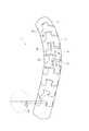
図1において、医療器具用可撓管(以下、可撓管と称する)1は、カテーテルや内視鏡等の医療器具に用いられる。この可撓管1は、ガイドワイヤ等の挿入物を挿通させるための内腔Sを有している。[First Embodiment]
In FIG. 1, a flexible tube for medical instruments (hereinafter referred to as a flexible tube) 1 is used for medical instruments such as catheters and endoscopes. The
可撓管1は、複数の管状体2と、先端部3とを備え、これら管状体2および先端部3が互いに回動自在に、かつ軸方向に連結されて構成される。
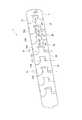
図2において、各管状体2は、それぞれ連結方向(管状体2の軸方向)の一方の端縁21に設けられた回動軸部22、凸部としての第1凸部23、および凸部としての第2凸部24と、それぞれ連結方向の他方の端縁25に設けられた回動支持部26、凹部としての第1凹部27、および凹部としての第2凹部28とを備えている。The
In FIG. 2, each
回動軸部22は、図3および図4にも示すように、端縁21における管状体2の中心軸に対して互いに対称な位置に一対設けられている。この回動軸部22は、端縁21から管状体2の軸方向に突出するとともに、平面視で円形状に形成されている。 As shown in FIGS. 3 and 4, a pair of
第1および第2凸部23,24は、端縁21の回動軸部22を挟んだ一方側および他方側において、回動軸部22とは異なる位置に設けられている。具体的に、第1および第2凸部23,24は、回動軸部22間の中央の位置であって、管状体2の中心軸に対して互いに対称な位置に設けられている。各凸部23,24は、端縁21から管状体2の連結方向に突出して形成され、第1凸部23の突出量は、第2凸部24の突出量よりも小さくなっている。また、各凸部23,24は、当該凸部23,24の突出方向に向かうにしたがって、当該突出に直交する幅寸法が次第に拡大する拡幅部231,241を備えている。さらに、各凸部23,24の先端縁232,242は、当該凸部23,24の突出方向に膨出する曲線状に形成されている。 The first and second
回動支持部26は、端縁25において管状体2の中心軸に対して互いに対称な位置に一対設けられ、連結される管状体2の回動軸部22を支持する。この回動支持部26は、端縁25が円形状に切り欠かれて形成されている。そして、回動支持部26と回動軸部22とで、ヒンジ構造が形成される。 A pair of the
第1および第2凹部27,28は、端縁25の回動支持部26を挟んだ一方側および他方側において、回動軸部22間の中央の位置であって、管状体2の中心軸に対して互いに対称な位置に設けられている。各凹部27,28は、端縁25から後退した凹状に切り欠かれて形成され、端縁25からの第1凹部27の後退量は、端縁25からの第2凹部28の後退量よりも大きくなっている。また、各凹部27,28は、当該凹部27,28の奥行き方向に向かうにしたがって、当該奥行き方向に直交する幅寸法が次第に縮小する狭幅部271,281と、奥行き方向に沿って当該奥行き方向に直交する幅寸法が一定に設けられ、各凸部23,24が摺接する摺接部273,283とを備えている。さらに、各凹部27,28の底縁272,282は、当該凹部27,28の奥行き方向に膨出する曲線状に形成されている。 The first and
先端部3は、円管状に形成されている。この先端部3の一方の端縁31、すなわち管状体2側の端縁31には、回動軸部32、第1凸部33、および第2凸部34が設けられている。これら回動軸部32、第1凸部33、および第2凸部34は、それぞれ管状体2の回動軸部22、第1凸部23、および第2凸部24と同様に形成されている。一方、先端部3の他方の端縁35には、回動支持部、第1凹部、および第2凹部は設けられていない The
以上の可撓管1において、各管状体2および先端部3は、連結される管状体2および先端部3の回動軸部22,32が回動支持部26に係合することで、互いに回動自在に連結されている。この際、管状体2の第1凹部27には、連結される管状体2および先端部3の第1凸部23,33が係合し、第2凹部28には、連結される管状体2および先端部3の第2凸部24,34が係合する。そして、可撓管1の湾曲時は、各凸部23,24,33,34の拡幅部231,241,331,341の最大幅部分が、各凹部27,28の摺接部273,283に摺接する。つまり、各凸部23,24,33,34と各凹部27,28とは、可撓管1の湾曲状態によらず当該可撓管1の周方向に常に当接していることになる。 In the
ここで、各管状体2の連結方向の端縁21,25において、第1凸部23側の領域211および第1凹部27側の領域251は、ヒンジ構造の回動軸である回動軸部22の回動中心から離れるにしたがって、管状体2の連結方向の長さ寸法が次第に縮小するように形成されている。すなわち、各端縁21,31の第1凸部23,33側の領域211,311と、向かい合う端縁25の第1凹部27側の領域251との間には、隙間G1が設けられ、回動軸部22または回動支持部26から離間するにしたがって、互いの間隔が大きくなる。
また、第1凸部23,33の先端縁232,332と当該第1凸部23,33が係合する第1凹部27の底縁272との間には、隙間G2が設けられている。Here, in the end edges 21 and 25 in the connecting direction of the
In addition, a gap G2 is provided between the
これに対し、端縁21,31の第2凸部24側の領域212,312と端縁25の第2凹部28側の領域252との間、および、第2凸部24,34の先端縁242,342と当該第2凸部24,34が係合する第2凹部28の底縁282との間には、隙間が設けられていない。一方、第2凸部24,34の拡幅部241,341と、第2凹部28の狭幅部281との間には、軸方向に隙間G3が設けられている。 On the other hand, between the
このため、管状体2は、図5および図6に示すように、回動軸部22,32を回動中心として、隙間G1〜G3分だけ第1凸部23、33および第1凹部27側に回動させることができるが、第2凸部24,34および第2凹部28側には回動させることができない。このように、可撓管1は、一方向にのみ湾曲可能に構成されている。 Therefore, as shown in FIGS. 5 and 6, the
具体的に、端縁21,25,31の領域211,251,311、先端縁232,332、底縁272、拡幅部241,341、および狭幅部281は、回動軸部22、32を回転中心とする同心円との交点が成す角度θ1,θ2,θ3が、それぞれ同じになるように形成されている。このことにより、可撓管1の最大湾曲時に、端縁21,31の領域211,311と端縁25の領域251、先端縁232,332と底縁272、および、拡幅部241,341と狭幅部281とを、それぞれ同時に当接させることができる。また、この際の当接面積を大きくすることができる。このため、可撓管1の最大湾曲時における軸方向の剛性を大幅に向上させることができる。 Specifically, the regions 211, 251, 311 of the end edges 21, 25, 31, the tip edges 232, 332, the
これに対し、端縁21,31の領域212,312と端縁25の領域252,312、および、先端縁242,342と底縁282とは、可撓管1が直線状態のときにそれぞれ当接する。このため、可撓管1が直線状態のときの当該可撓管1の軸方向の剛性を大幅に向上させることができる。 On the other hand, the
また、可撓管1は、体内への導入を可能にするため、その外形を数ミリ程度と非常に小さくする必要がある。一方、可撓管1の内部には、ガイドワイヤ等の挿入物が挿通されるため、可撓管1の内径は、出来る限り大きくすることが望ましい。このため、可撓管1の外径は1〜20[mm]程度(望ましくは1〜5[mm])、内径は0.4〜18[mm]程度(望ましくは0.4〜4.4[mm])、肉厚は0.1〜1[mm]程度(望ましくは0.25〜0.5[mm])とされている。 In addition, the
このような可撓管1は、例えば、上記外径および内径を有したステンレス製の円管状部材をレーザー加工することにより得られる。レーザー加工を用いた場合、円管状部材をレーザーで切断するだけで、管状体2および先端部3が互いに連結された状態の可撓管1を容易に得ることができる。
なお、可撓管1の材質および製造方法は、上記のものに限らず、任意のものを用いることができる。Such a
In addition, the material and manufacturing method of the
本実施形態によれば、次のような効果がある。
すなわち、管状体2の各凹部27,28には、連結される管状体2または先端部3の各凸部23,24,33,34が係合するため、可撓管1に作用する外力を各凹部27,28や各凸部23,24,33,34で受けることができる。このことにより、回動軸部22,32および回動支持部26以外の部分でも外力を受けることができるので、外力に対して十分な剛性を確保することができる。
また、各凸部23,24,33,34が、連結される管状体2の各凹部27,28に係合しているため、管状体2間または管状体2と先端部3との間が、各凸部23,24,33,34により橋渡しされることになる。このことにより、可撓管1内への挿入物が各凸部23,24,33,34に当接して案内されるため、挿入物が管状体2の連結方向の端縁21,25,31に引っ掛かりにくくなり、挿入物を容易に挿通することができる。According to this embodiment, there are the following effects.
That is, since each
Moreover, since each
さらに、可撓管1の湾曲に伴って、湾曲の外側に位置する第2凹部28と当該第2凹部28に係合する第2凸部24,34との間隔が拡がることで、第2凸部24,34が第2凹部28から抜け出す方向に移動した場合、第2凸部24,34の拡幅部241,341が第2凹部28の狭幅部281にくさび状に入り込むことになる。このことにより、第2凸部24,34が第2凹部28に引っ掛かることになるため、最大湾曲時の可撓管1の引っ張り剛性を向上させることができ、可撓管1の剛性を一層高めることができる。さらに、可撓管1が直線状の状態において、湾曲の内側に位置する第1凹部27および第1凸部23,33を、第1凸部23,33の拡幅部231,331が第1凹部27の狭幅部271にくさび状に入り込んだ状態で係合させておけば、可撓管1の直線状態の引っ張り剛性も向上させることができる。 Further, as the
また、各凹部27,28には、各凸部23,24,33,34が摺接する摺接部273,283が奥行き方向に向けて設けられているため、可撓管1の湾曲状態によらず、凹部27,28と凸部23,24,33,34とが互いの幅方向に、つまり管状体2および先端部3の周方向に当接し続けることになる。このため、可撓管1に管状体2の軸回りの回転力が加わった際に、回動軸部以外でも当該回転力を受けることができる。従って、可撓管1のねじれ剛性を向上させることができ、可撓管1の剛性を一層高めることができる。 In addition, the
さらに、拡幅部231,241,331,341の最大幅部分が各凹部27,28の摺接部273,283に摺接するため、拡幅部231,241,331,341以外に各凹部27,28との摺接用の部分を設ける必要がない。このため、各凸部23,24,33,34の突出量および各凹部27,28の奥行き量を抑えつつ、各凸部23,24,33,34と各凹部27,28との摺接状態を保つことができる。このことにより、各凸部23,24,33,34および各凹部27,28の剛性を向上させ、かつ連結される管状体2の長さを短くすることができる。従って、可撓管1の剛性を一層高めることができるとともに、可撓管1の湾曲部の長さを短くすることができる。 Further, since the maximum width portions of the widened
また、各凸部23,24,33,34の先端縁232,242,332,342と各凹部27,28の底縁272,282とが、それぞれ曲線状に形成されている。このため、可撓管1内への挿入物を先端縁232,242,332,342または底縁272,282の形状に沿って案内することができる。このことにより、挿入物が先端縁232,242,332,342または底縁272,282に引っ掛かることを抑制することができるので、挿入物を可撓管1内に速やかに挿通させることができる。 Moreover, the front edge 232,242,332,342 of each
また、各管状体2の連結方向の端縁21,25は、回動軸から離れるにしたがって、当該管状体2の連結方向の長さ寸法が次第に縮小する。このため、互いに連結された管状体2の向かい合う端縁21,25同士、および管状体2の端縁25と先端部3の端縁31とは、回動軸から離間するにしたがって、互いの間隔が大きくなる。このため、可撓管1の湾曲時に、管状体2の回動によって端縁21,25,31同士の間隔が狭まった場合でも、これら端縁21,25,31が互いに干渉することを防止できる。 Further, the
〔第2実施形態〕
次に、本発明の第2実施形態を図7および図8に基づいて説明する。
本実施形態の可撓管1は、それぞれ形状が異なる管状体としての第1および第2管状体2A,2Bを備え、これら管状体2A,2Bが交互に連結された点が、第1実施形態と相違する。[Second Embodiment]
Next, a second embodiment of the present invention will be described with reference to FIGS.
The
具体的に、第1管状体2Aは、図7および図8に示すように、第1実施形態の管状体2に対して、第1凸部23と第2凸部24との位置が入れ替わった構成を有している。
一方、第2管状体2Bは、第1実施形態の管状体2に対して、第1凹部27と第2凹部28との位置が入れ替わった構成を有している。Specifically, as shown in FIGS. 7 and 8, the first
On the other hand, the 2nd
この場合、第1管状体2Aおよび第2管状体2Bには、第1管状体2Aの回動軸部22Aを回動中心として、図7に矢印D1で示す一方の方向の相対回転が許容される。さらに、各管状体2A,2Bには、第2管状体2Bの回動軸部22Bを回動中心として、図7に矢印D2で示す他方の方向の相対回転が許容される。つまり、可撓管1は、相反する二方向に湾曲可能に構成されている。 In this case, the first
本実施形態によれば、第1実施形態の効果に加えて、次のような効果がある。
すなわち、可撓管1は、相反する二方向に湾曲可能に構成されているので、可撓管1の湾曲の自由度を高めることができる。例えば、可撓管1を図7の手前方向に湾曲させたり、図7の奥行方向に湾曲させたりすることができる。また、図7の手前方向と奥行方向に同時に湾曲させることで、可撓管1をS字状に湾曲させることもできる。このため、可撓管1の利便性をより向上させることができる。According to the present embodiment, in addition to the effects of the first embodiment, there are the following effects.
That is, since the
〔第3実施形態〕
次に、本発明の第3実施形態を図9および図10に基づいて説明する。
本実施形態の可撓管1では、第1凸部23および第1凹部27の形状と、端縁21,25,31における第1凸部23、33または第1凹部27の反対側の領域の形状とが、第1実施形態と相違する。[Third Embodiment]
Next, a third embodiment of the present invention will be described with reference to FIGS.
In the
具体的に、第1凸部23は、平面視矩形状に形成され、第1凹部27も、第1凸部23に対応して平面視矩形状に形成されている。一方、端縁21,31における第1凸部23,33の反対側の領域と、端縁25における第1凹部27の反対側の領域とは、側面視で直線状に形成されている。すなわち、管状体2および先端部3には、第2凸部24,34および第2凹部28が設けられていない。 Specifically, the first
また、可撓管1が直線状の状態で、第1凸部23の先端縁232と第1凹部27の底縁272との間、および、端縁21の第1凸部23側領域と端縁25の第1凹部27側領域との間には、隙間G2が設けられている。一方、端縁21,31における第1凸部23,33の反対側の領域と、端縁25における第1凹部27の反対側の領域との間には、隙間が設けられていない。このため、可撓管1は、回動軸部22および回動支持部26を回動中心として、第1凸部23および第1凹部27側にのみ湾曲させることができる。 Further, in a state where the
本実施形態によれば、次のような効果がある。
すなわち、管状体2および先端部3が簡易な形状とされているため、管状体2および先端部3の形成が容易になる。このため、可撓管1を容易に製造することができ、可撓管1の製造コストを低減することができる。According to this embodiment, there are the following effects.
That is, since the
〔前記実施形態の適用例〕
次に、前記実施形態に係る可撓管の医療器具への適用例を図面に基づいて説明する。[Application example of the embodiment]
Next, an application example of the flexible tube according to the embodiment to a medical instrument will be described with reference to the drawings.
〔第1適用例〕
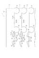
本適用例に係る医療器具10は、図11に示すように、ガイディングカテーテル6と、ガイディングカテーテル6内に進退自在に設けられ、拡張体としてのバルーン71を有するバルーンカテーテル7とを備えている。ガイディングカテーテル6は、第1から第3実施形態のいずれかの可撓管1を有するガイディングカテーテル6と、可撓管1の基端部に接続されたハブ4と、可撓管1の湾曲位置を固定する位置固定具5とを備えている。[First application example]
As shown in FIG. 11, the
ハブ4は、可撓管1の内腔Sと外部とを連通する導入路41を備え、導入路41を介してバルーンカテーテル7等の挿入物を可撓管1の内腔Sへ挿入可能に構成されている。また、可撓管1には、導入路41から分岐する排出路42が設けられ、体内の液体を排出路42から排出可能に構成されている。 The
位置固定具5は、ハブ4に回動自在に設けられ、この位置固定具5と、可撓管1の先端部3とは、図示しないワイヤ等で接続されている。このため、位置固定具5を回転させることで、可撓管1の湾曲位置を調節できるとともに、当該湾曲位置を固定することができる。 The
このような構成の医療器具10は、例えば、副鼻腔炎の治療に用いることができる。具体的には、ガイディングカテーテル6を鼻から挿入し、鼻腔内の形状に合わせて可撓管1を湾曲させつつ、副鼻腔まで到達させる。この状態で、ガイディングカテーテル6の内腔Sにバルーンカテーテル7を挿通させ、副鼻腔における閉塞気味の自然孔内でバルーン71を膨らませて、自然孔を開大させる。 The
副鼻腔は、4箇所存在するとともに、個々人で位置が異なり、かつ到達までの通路が狭いため、従来は、鼻腔内の形状や副鼻腔の位置等に応じて、湾曲形状の異なる複数のガイディングカテーテルを用いていた。
これに対し、本実施形態によれば、医療器具10は、湾曲可能な可撓管1を備えているため、可撓管1の湾曲量を変化させつつ、ガイディングカテーテル6を副鼻腔まで容易に到達させることができる。このことにより、ガイディングカテーテル6を交換する必要がなくなるので、副鼻腔炎の治療に要する医療器具数を削減することができるとともに、ガイディングカテーテル6の交換の手間および交換に要する時間を短縮することができる。
また、医療器具10は、前述した可撓管1を備えているため、外力に対する剛性を確保しつつ、ガイディングカテーテル6を湾曲自在に体内に挿入することができるとともに、副鼻腔の狭窄部でバルーンカテーテル7を拡張させることで、当該狭窄部を拡張治療することができる。Since there are four sinuses, each person has a different position, and the passage to reach is narrow, conventionally, multiple guidings with different curved shapes depending on the shape of the nasal cavity, the position of the sinuses, etc. A catheter was used.
On the other hand, according to this embodiment, since the
In addition, since the
〔第2適用例〕
本適用例に係る医療器具としてのバルーンカテーテル8は、図12に示すように、第1から第3実施形態のいずれかの可撓管1と、可撓管1の基端部に接続されたハブ4と、可撓管1の湾曲位置を固定する位置固定具5と、可撓管1の先端部に設けられた拡張体としてのバルーン81とを備えている。
このような構成のバルーンカテーテル8によっても、第1適用例と同様の効果を得ることができる。[Second application example]
A balloon catheter 8 as a medical instrument according to this application example is connected to the
Also with the balloon catheter 8 having such a configuration, the same effect as in the first application example can be obtained.
なお、本発明は前述の実施形態に限定されるものではなく、本発明の目的を達成できる範囲での変形、改良等は本発明に含まれるものである。
例えば、管状体2の各凸部23,24は、回動軸部22が設けられた端縁21に設けられ、各凹部27,28は、回動支持部26が設けられた端縁25に設けられていたが、これに限らない。例えば、各凸部23,24を端縁25に設けたり、各凹部27,28を端縁21に設けたりしてもよい。It should be noted that the present invention is not limited to the above-described embodiments, and modifications, improvements, and the like within the scope that can achieve the object of the present invention are included in the present invention.
For example, the
前記第1および第2実施形態では、各凸部23,24は拡幅部231,241を備え、各凹部27,28は狭幅部271,281を備えていたが、第3実施形態と同様に、各凸部23,24および各凹部27,28を平面視矩形状に形成してもよい。この場合、各凹部27,28に対する各凸部23,24の軸方向の係合量を、最大回動時の各凹部27,28と各凸部23,24との相対移動量よりも大きくすれば、回動状態によらず各凸部23,24を各凹部27,28に係合させることができる。このため、可撓管1が最大限湾曲した状態でも、各凸部23,24と各凹部27,28との係合が解除されることを防止することができ、可撓管1の剛性を十分に確保することができる。 In the first and second embodiments, the
前記実施形態の適用例では、可撓管1をガイディングカテーテル6に適用したが、本発明の医療器具としては、これに限らない。要するに、本発明の医療器具としては、複数の管状体が連結された可撓管を有するものであればよく、例えば、ガイディングカテーテル6以外の種類のカテーテルや、内視鏡にも適用することができる。また、管状体の断面形状は真円に限定されず、例えば楕円や多角形など、管状体の軸方向と直交する平面において点対称である部材を使用することができる。 In the application example of the embodiment, the
本発明は、可撓管を備えたあらゆる医療器具に利用できる。 The present invention can be used for any medical instrument provided with a flexible tube.
1 可撓管(医療器具用可撓管)
2 管状体
2A 第1管状体
2B 第2管状体
21 端縁
22 回動軸部
23 第1凸部(凸部)
231 拡幅部
24 第2凸部(凸部)
241 拡幅部
25 端縁
26 回動支持部
27 第1凹部(凹部)
271 狭幅部
273 摺接部
28 第2凹部(凹部)
281 狭幅部
283 摺接部
3 先端部
31 端縁
32 回動軸部
33 第1凸部
331 拡幅部
34 第2凸部
341 拡幅部
35 端縁
4 ハブ
41 導入路
42 排出路
5 位置固定具
6 ガイディングカテーテル
7 バルーンカテーテル
71 バルーン
8 バルーンカテーテル(医療器具)
81 バルーン
10 医療器具1 Flexible tube (flexible tube for medical equipment)
2
231
241 Widening
271
281
81
Claims (6)
Translated fromJapaneseヒンジ構造により互いに回動自在に連結された複数の管状体を備え、
各管状体は、
連結方向の一方の端縁に設けられ、前記ヒンジ構造を形成する回動軸部と、
前記連結方向の他方の端縁に設けられ、連結される管状体の回動軸部を支持する回動支持部と、
前記回動軸部が設けられた端縁および前記回動支持部が設けられた端縁のいずれか一方に設けられ、前記回動軸部または前記回動支持部とは異なる位置から前記連結方向に突出する凸部と、
前記回動軸部が設けられた端縁および前記回動支持部が設けられた端縁のいずれか他方に設けられ、連結される管状体の凸部が係合する凹部とを備え、
前記凸部は、当該凸部の突出方向に向かうにしたがって、当該突出方向に直交する幅寸法が次第に拡大する拡幅部を備え、
前記凹部は、当該凹部の奥行き方向に沿って当該奥行き方向に直交する幅寸法が一定に設けられ、前記凸部が摺接する摺接部と、奥行き方向の反対方向に向かうにしたがって、当該奥行き方向に直交する幅寸法が次第に縮小する狭幅部とを備え、
前記摺接部には、前記拡幅部の最大幅部分が摺接し、
前記一方の端縁、前記他方の端縁、前記凸部、および前記凹部は、当該医療器具用可撓管の湾曲時に、前記連結方向に隣り合う一方の端縁と他方の端縁とが、かつ前記凸部の先端縁と前記凹部の底縁とが、それぞれ同時に当接可能に構成されていることを特徴とする医療器具用可撓管。A flexible tube for a medical device,
A plurality of tubular bodies connected to each other by a hinge structure so as to be rotatable,
Each tubular body is
A rotation shaft provided on one end edge in the connecting direction and forming the hinge structure;
A rotation support portion that is provided at the other end edge of the connection direction and supports the rotation shaft portion of the connected tubular body;
The connection direction from a position different from the rotation shaft portion or the rotation support portion is provided on either the edge provided with the rotation shaft portion or the edge provided with the rotation support portion. A convex portion protruding into
A concave portion that is provided on either one of an edge provided with the rotation shaft portion and an edge provided with the rotation support portion, and is engaged with a convex portion of a tubular body to be connected;
The convex portion includes a widened portion in which a width dimension orthogonal to the projecting direction gradually expands toward the projecting direction of the convex portion,
The concave portion has a constant width dimension perpendicular to the depth direction along the depth direction of the concave portion, and the depth direction as it goes in the opposite direction of the depth direction with the sliding contact portion with which the convex portion slides. And a narrow portion where the width dimension perpendicular to the width gradually decreases,
The said sliding contact portion, the widest part of the wider sectionis sliding,
The one end edge, the other end edge, the convex portion, and the concave portion are, when the flexible tube for a medical instrument is curved, one end edge and the other end edge adjacent to each other in the connection direction. And the flexible tube for medical instruments characterizedby the front- endedge of the said convex part and the bottom edge of the said recessed part contact | abutting simultaneously, respectively .
前記凸部および前記凹部は、前記ヒンジ構造の回動軸を挟んだ一方側および他方側のそれぞれに設けられ、
当該医療器具用可撓管が直線状態のときに前記一方側の凸部の先端縁が前記一方側の凹部の底縁と当接し、
当該医療器具用可撓管が湾曲したときに前記他方側の凸部の先端縁が前記他方側の凹部の底縁と当接することを特徴とする医療器具用可撓管。The flexible tube for a medical instrument accordingto claim1 ,
The convex portion and the concave portion are provided on each of one side and the other side across the rotation shaft of the hinge structure,
When the flexible tube for medical equipment is in a straight line state, the tip edge of the convex portion on one side is in contact with the bottom edge of the concave portion on the one side,
A flexible tube for a medical instrument, wherein the distal end edge of the convex part on the other side abuts on the bottom edge of the concave part on the other side when the flexible tube for medical instrument is curved.
前記凸部の先端縁は、当該凸部の突出方向に膨出する曲線状に形成され、
前記凹部の底縁は、当該凹部の奥行き方向に膨出する曲線状に形成されていることを特徴とする医療器具用可撓管。In the flexible tube for medical instruments according toclaim 1or 2 ,
The leading edge of the convex portion is formed in a curved shape that bulges in the protruding direction of the convex portion,
A flexible tube for a medical instrument, wherein the bottom edge of the recess is formed in a curved shape that bulges in the depth direction of the recess.
各管状体の連結方向の端縁は、前記ヒンジ構造の回動軸から離れるにしたがって、当該管状体の連結方向の長さ寸法が次第に縮小するように形成されていることを特徴とする医療器具用可撓管。In the flexible tube for medical instruments according to any one of claims 1 to3 ,
An end edge in the connecting direction of each tubular body is formed so that the length dimension in the connecting direction of the tubular body gradually decreases as the distance from the pivot shaft of the hinge structure increases. Flexible tube.
前記医療器具用可撓管の湾曲位置を固定する位置固定具とを備えていることを特徴とする医療器具。A flexible tube for a medical instrument according to any one of claims 1 to4 ,
A medical instrument, comprising: a position fixing tool that fixes a bending position of the flexible tube for the medical instrument.
前記医療器具用可撓管の外周上に設けられ、または、前記医療器具用可撓管内に進退自在に設けられ、当該医療器具用可撓管の径方向に拡張する拡張体を備えていることを特徴とする医療器具。The medical instrument according to claim5 ,
It is provided on the outer periphery of the flexible tube for medical instruments, or is provided in the flexible tube for medical instruments so as to be able to advance and retreat, and has an expansion body that expands in the radial direction of the flexible tube for medical instruments. A medical instrument characterized by
Priority Applications (3)
| Application Number | Priority Date | Filing Date | Title |
|---|---|---|---|
| JP2012042248AJP6034573B2 (en) | 2012-02-28 | 2012-02-28 | Flexible tube for medical device and medical device |
| PCT/JP2013/001011WO2013128860A1 (en) | 2012-02-28 | 2013-02-22 | Flexible tube for medical instrument and medical instrument |
| US13/779,064US9113783B2 (en) | 2012-02-28 | 2013-02-27 | Flexible tube for medical instrument and medical instrument |
Applications Claiming Priority (1)
| Application Number | Priority Date | Filing Date | Title |
|---|---|---|---|
| JP2012042248AJP6034573B2 (en) | 2012-02-28 | 2012-02-28 | Flexible tube for medical device and medical device |
Publications (2)
| Publication Number | Publication Date |
|---|---|
| JP2013176465A JP2013176465A (en) | 2013-09-09 |
| JP6034573B2true JP6034573B2 (en) | 2016-11-30 |
Family
ID=47901253
Family Applications (1)
| Application Number | Title | Priority Date | Filing Date |
|---|---|---|---|
| JP2012042248AActiveJP6034573B2 (en) | 2012-02-28 | 2012-02-28 | Flexible tube for medical device and medical device |
Country Status (3)
| Country | Link |
|---|---|
| US (1) | US9113783B2 (en) |
| JP (1) | JP6034573B2 (en) |
| WO (1) | WO2013128860A1 (en) |
Families Citing this family (69)
| Publication number | Priority date | Publication date | Assignee | Title |
|---|---|---|---|---|
| US9254123B2 (en) | 2009-04-29 | 2016-02-09 | Hansen Medical, Inc. | Flexible and steerable elongate instruments with shape control and support elements |
| US20120071752A1 (en) | 2010-09-17 | 2012-03-22 | Sewell Christopher M | User interface and method for operating a robotic medical system |
| US20130030363A1 (en) | 2011-07-29 | 2013-01-31 | Hansen Medical, Inc. | Systems and methods utilizing shape sensing fibers |
| US10149720B2 (en) | 2013-03-08 | 2018-12-11 | Auris Health, Inc. | Method, apparatus, and a system for facilitating bending of an instrument in a surgical or medical robotic environment |
| US20140277334A1 (en) | 2013-03-14 | 2014-09-18 | Hansen Medical, Inc. | Active drives for robotic catheter manipulators |
| US9282993B1 (en)* | 2013-03-15 | 2016-03-15 | Southern Methodist University | Steerable extendable devices |
| US10376672B2 (en) | 2013-03-15 | 2019-08-13 | Auris Health, Inc. | Catheter insertion system and method of fabrication |
| US11006975B1 (en) | 2013-03-15 | 2021-05-18 | Southern Methodist University | Steerable extendable devices |
| WO2015108044A1 (en)* | 2014-01-15 | 2015-07-23 | テルモ株式会社 | Medical retaining device |
| DE102014205556A1 (en)* | 2014-03-25 | 2015-10-01 | Richard Wolf Gmbh | Endoscopic instrument |
| US9744335B2 (en) | 2014-07-01 | 2017-08-29 | Auris Surgical Robotics, Inc. | Apparatuses and methods for monitoring tendons of steerable catheters |
| US10792464B2 (en) | 2014-07-01 | 2020-10-06 | Auris Health, Inc. | Tool and method for using surgical endoscope with spiral lumens |
| US9561083B2 (en) | 2014-07-01 | 2017-02-07 | Auris Surgical Robotics, Inc. | Articulating flexible endoscopic tool with roll capabilities |
| EP3009104B1 (en)* | 2014-10-14 | 2019-11-20 | St. Jude Medical, Cardiology Division, Inc. | Flexible catheter and methods of forming same |
| JP6631769B2 (en)* | 2014-12-11 | 2020-01-15 | 学校法人 中央大学 | Tubular moving body |
| JP6440860B2 (en)* | 2015-03-02 | 2018-12-19 | コーニンクレッカ フィリップス エヌ ヴェKoninklijke Philips N.V. | Variable configuration bending neck for articulating ultrasonic probes |
| US11819636B2 (en) | 2015-03-30 | 2023-11-21 | Auris Health, Inc. | Endoscope pull wire electrical circuit |
| WO2017021993A1 (en)* | 2015-07-31 | 2017-02-09 | マルホ発條工業株式会社 | Slit pipe and medical-treatment shaft member in which same is used |
| JP7082052B2 (en) | 2015-09-03 | 2022-06-07 | ネプチューン メディカル インク. | A device for advancing the endoscope in the small intestine |
| CN108348133B (en) | 2015-09-09 | 2020-11-13 | 奥瑞斯健康公司 | Instrument Manipulators for Surgical Robotic Systems |
| US10806901B2 (en)* | 2015-10-28 | 2020-10-20 | Becton, Dickinson And Company | Catheter adapter with distal inner diameter curvature providing kink resistance |
| US9949749B2 (en) | 2015-10-30 | 2018-04-24 | Auris Surgical Robotics, Inc. | Object capture with a basket |
| US9955986B2 (en) | 2015-10-30 | 2018-05-01 | Auris Surgical Robotics, Inc. | Basket apparatus |
| US10231793B2 (en) | 2015-10-30 | 2019-03-19 | Auris Health, Inc. | Object removal through a percutaneous suction tube |
| US10434288B2 (en)* | 2016-01-15 | 2019-10-08 | Cook Medical Technologies Llc | Locking medical guide wire |
| US20180193608A1 (en)* | 2016-01-15 | 2018-07-12 | Cook Medical Technologies Llc | Modular medical guide wire assembly |
| JP2019165754A (en)* | 2016-08-16 | 2019-10-03 | テルモ株式会社 | Medical elongated body |
| EP3500151A4 (en) | 2016-08-18 | 2020-03-25 | Neptune Medical Inc. | DEVICE AND METHOD FOR IMPROVED VISUALIZATION OF THE SMALL BOWEL |
| US10463439B2 (en) | 2016-08-26 | 2019-11-05 | Auris Health, Inc. | Steerable catheter with shaft load distributions |
| KR20230096148A (en) | 2016-08-31 | 2023-06-29 | 아우리스 헬스, 인코포레이티드 | Length conservative surgical instrument |
| US10682192B2 (en)* | 2016-09-30 | 2020-06-16 | Intuitive Surgical Operations, Inc. | Variable-length guide apparatus for delivery of a flexible instrument and methods of use |
| CN107091261B (en)* | 2017-02-14 | 2020-10-09 | 珠海普生医疗科技有限公司 | Snake bone processing method |
| US11007347B2 (en)* | 2017-04-26 | 2021-05-18 | Biosense Webster (Israel) Ltd. | Deflectable insertion tool |
| CN106937897A (en)* | 2017-04-26 | 2017-07-11 | 上海百心安生物技术有限公司 | The Transmission system and preparation method of a kind of bioabsorbable stent |
| US11376401B2 (en) | 2017-04-26 | 2022-07-05 | Acclarent, Inc. | Deflectable guide for medical instrument |
| KR102576296B1 (en) | 2017-05-17 | 2023-09-08 | 아우리스 헬스, 인코포레이티드 | Interchangeable working channels |
| US11026758B2 (en) | 2017-06-28 | 2021-06-08 | Auris Health, Inc. | Medical robotics systems implementing axis constraints during actuation of one or more motorized joints |
| CN107518861A (en)* | 2017-06-29 | 2017-12-29 | 杭州无创光电有限公司 | Snake osteon and snake bone structure |
| CN107518860A (en)* | 2017-06-29 | 2017-12-29 | 杭州无创光电有限公司 | Endoscope snake bone structure and endoscope |
| CN107334449A (en)* | 2017-07-11 | 2017-11-10 | 上海成运医疗器械股份有限公司 | Endoscope-use is without rivet snake bone component |
| JP7379321B2 (en)* | 2017-07-20 | 2023-11-14 | ネプチューン メディカル インク. | Dynamically rigid overtube |
| DE102017123975A1 (en)* | 2017-10-16 | 2019-04-18 | Hoya Corporation | Method of making an introducer tube of an endoscope and endoscope with an introducer tube |
| EP3737451A4 (en)* | 2018-01-11 | 2021-10-20 | The United States Government as Represented by The Department of Veterans Affairs | SAMPLING CATHETER WITH ARTICULATED TIP |
| CN117017505A (en) | 2018-03-28 | 2023-11-10 | 奥瑞斯健康公司 | Composite instrument and robotic system |
| US10624683B2 (en) | 2018-04-25 | 2020-04-21 | Loubert S. Suddaby | Segmented alignment rod assembly |
| US11580268B2 (en) | 2018-04-25 | 2023-02-14 | Loubert S. Suddaby | Method of creating a customized segmented alignment rod for alignment of a spine |
| US11317949B2 (en) | 2018-04-25 | 2022-05-03 | Loubert S. Suddaby | Segmented alignment rod assembly |
| CN108553069B (en)* | 2018-05-17 | 2020-08-28 | 黄琴 | Controllable bent pipe structure |
| CN108553070B (en)* | 2018-05-17 | 2020-09-18 | 黄琴 | Controllable bent pipe structure |
| US12059128B2 (en) | 2018-05-31 | 2024-08-13 | Neptune Medical Inc. | Device and method for enhanced visualization of the small intestine |
| KR102712920B1 (en) | 2018-06-27 | 2024-10-07 | 아우리스 헬스, 인코포레이티드 | Alignment and attachment systems for medical devices |
| CN112714658A (en) | 2018-07-19 | 2021-04-27 | 海王星医疗公司 | Dynamic rigidized composite medical structure |
| WO2020033318A1 (en) | 2018-08-07 | 2020-02-13 | Auris Health, Inc. | Combining strain-based shape sensing with catheter control |
| CN112804933B (en) | 2018-09-26 | 2024-10-18 | 奥瑞斯健康公司 | Articulating medical device |
| WO2020069080A1 (en) | 2018-09-28 | 2020-04-02 | Auris Health, Inc. | Devices, systems, and methods for manually and robotically driving medical instruments |
| WO2020139973A1 (en)* | 2018-12-28 | 2020-07-02 | Auris Health, Inc. | Medical instrument with articulable segment |
| US11617627B2 (en) | 2019-03-29 | 2023-04-04 | Auris Health, Inc. | Systems and methods for optical strain sensing in medical instruments |
| US11793392B2 (en) | 2019-04-17 | 2023-10-24 | Neptune Medical Inc. | External working channels |
| WO2020214221A1 (en) | 2019-04-17 | 2020-10-22 | Neptune Medical Inc. | Dynamically rigidizing composite medical structures |
| WO2021028883A1 (en) | 2019-08-15 | 2021-02-18 | Auris Health, Inc. | Medical device having multiple bending sections |
| US11896330B2 (en) | 2019-08-15 | 2024-02-13 | Auris Health, Inc. | Robotic medical system having multiple medical instruments |
| US11737845B2 (en) | 2019-09-30 | 2023-08-29 | Auris Inc. | Medical instrument with a capstan |
| CN114901188A (en) | 2019-12-31 | 2022-08-12 | 奥瑞斯健康公司 | Dynamic pulley system |
| EP4084724A4 (en) | 2019-12-31 | 2023-12-27 | Auris Health, Inc. | ADVANCED BASKET DRIVE MODE |
| CA3178444A1 (en) | 2020-03-30 | 2021-10-07 | Neptune Medical Inc. | Layered walls for rigidizing devices |
| KR20230133374A (en) | 2021-01-29 | 2023-09-19 | 넵튠 메디컬 인코포레이티드 | Device and method for preventing inadvertent movement of a dynamic stiffening device |
| CN113576378B (en)* | 2021-08-11 | 2024-07-05 | 岱川医疗(深圳)有限责任公司 | Bending structure of endoscope |
| KR20250003955A (en) | 2022-04-27 | 2025-01-07 | 넵튠 메디컬 인코포레이티드 | Sanitary outer covering for endoscope |
| US12330292B2 (en) | 2023-09-28 | 2025-06-17 | Neptune Medical Inc. | Telescoping robot |
Family Cites Families (10)
| Publication number | Priority date | Publication date | Assignee | Title |
|---|---|---|---|---|
| DE19535179A1 (en)* | 1995-09-22 | 1997-03-27 | Wolf Gmbh Richard | Angled pipe and process for its manufacture |
| US5749828A (en)* | 1995-12-22 | 1998-05-12 | Hewlett-Packard Company | Bending neck for use with invasive medical devices |
| JPH11155806A (en)* | 1997-11-28 | 1999-06-15 | Olympus Optical Co Ltd | Endoscope |
| US6364828B1 (en)* | 2000-01-06 | 2002-04-02 | Hubert K. Yeung | Elongated flexible inspection neck |
| US7578786B2 (en)* | 2003-04-01 | 2009-08-25 | Boston Scientific Scimed, Inc. | Video endoscope |
| US7758520B2 (en) | 2003-05-27 | 2010-07-20 | Boston Scientific Scimed, Inc. | Medical device having segmented construction |
| US9271720B2 (en)* | 2005-08-11 | 2016-03-01 | Biomet Sports Medicine, Llc | Steerable suture passing device |
| DE102005054057B4 (en)* | 2005-11-10 | 2017-12-14 | Schölly Fiberoptic GmbH | component |
| EP1977677B1 (en)* | 2007-04-04 | 2009-08-19 | Richard Wolf GmbH | Endoscopic instrument |
| EP2581031A1 (en)* | 2011-10-13 | 2013-04-17 | Johann Klaffenböck | Bending device |
- 2012
- 2012-02-28JPJP2012042248Apatent/JP6034573B2/enactiveActive
- 2013
- 2013-02-22WOPCT/JP2013/001011patent/WO2013128860A1/enactiveApplication Filing
- 2013-02-27USUS13/779,064patent/US9113783B2/enactiveActive
Also Published As
| Publication number | Publication date |
|---|---|
| WO2013128860A1 (en) | 2013-09-06 |
| US9113783B2 (en) | 2015-08-25 |
| US20130226151A1 (en) | 2013-08-29 |
| JP2013176465A (en) | 2013-09-09 |
Similar Documents
| Publication | Publication Date | Title |
|---|---|---|
| JP6034573B2 (en) | Flexible tube for medical device and medical device | |
| EP3666203B1 (en) | Deflectable insertion tool | |
| CN108836501B (en) | Method for producing deflectable insertion tools | |
| CN113873955B (en) | Steerable device including a hinge with a slotted structure | |
| JP6364016B2 (en) | Coaxial bidirectional catheter | |
| JP2015536226A5 (en) | ||
| US20080249364A1 (en) | Endoscopic instrument | |
| JP2012527918A (en) | Surgical instruments | |
| JP5625122B2 (en) | Medical treatment tool | |
| US10596363B2 (en) | Medical treatment tool | |
| US20210251468A1 (en) | Medical device and treatment system | |
| JP6878769B2 (en) | Diameter reduction device | |
| CN118217514B (en) | Hypotube and have this microcatheter for hypotubes | |
| NL2022849B1 (en) | Steerable instrument comprising a hinge with a slotted structure | |
| WO2018034307A1 (en) | Long medical instrument | |
| JP2025515769A (en) | Bendable tube for use with an endoscope - Patent application | |
| JP2023131174A (en) | medical equipment | |
| WO2018034306A1 (en) | Long medical instrument |
Legal Events
| Date | Code | Title | Description |
|---|---|---|---|
| A621 | Written request for application examination | Free format text:JAPANESE INTERMEDIATE CODE: A621 Effective date:20150119 | |
| A131 | Notification of reasons for refusal | Free format text:JAPANESE INTERMEDIATE CODE: A131 Effective date:20151006 | |
| A521 | Request for written amendment filed | Free format text:JAPANESE INTERMEDIATE CODE: A523 Effective date:20151203 | |
| A02 | Decision of refusal | Free format text:JAPANESE INTERMEDIATE CODE: A02 Effective date:20160510 | |
| A521 | Request for written amendment filed | Free format text:JAPANESE INTERMEDIATE CODE: A523 Effective date:20160805 | |
| A911 | Transfer to examiner for re-examination before appeal (zenchi) | Free format text:JAPANESE INTERMEDIATE CODE: A911 Effective date:20160823 | |
| TRDD | Decision of grant or rejection written | ||
| A01 | Written decision to grant a patent or to grant a registration (utility model) | Free format text:JAPANESE INTERMEDIATE CODE: A01 Effective date:20161011 | |
| A61 | First payment of annual fees (during grant procedure) | Free format text:JAPANESE INTERMEDIATE CODE: A61 Effective date:20161028 | |
| R150 | Certificate of patent or registration of utility model | Ref document number:6034573 Country of ref document:JP Free format text:JAPANESE INTERMEDIATE CODE: R150 | |
| R250 | Receipt of annual fees | Free format text:JAPANESE INTERMEDIATE CODE: R250 | |
| R250 | Receipt of annual fees | Free format text:JAPANESE INTERMEDIATE CODE: R250 | |
| R250 | Receipt of annual fees | Free format text:JAPANESE INTERMEDIATE CODE: R250 | |
| R250 | Receipt of annual fees | Free format text:JAPANESE INTERMEDIATE CODE: R250 | |
| R250 | Receipt of annual fees | Free format text:JAPANESE INTERMEDIATE CODE: R250 | |
| R250 | Receipt of annual fees | Free format text:JAPANESE INTERMEDIATE CODE: R250 |