JP6033897B2 - Compound interbody device and manufacturing method - Google Patents
Compound interbody device and manufacturing methodDownload PDFInfo
- Publication number
- JP6033897B2 JP6033897B2JP2015021025AJP2015021025AJP6033897B2JP 6033897 B2JP6033897 B2JP 6033897B2JP 2015021025 AJP2015021025 AJP 2015021025AJP 2015021025 AJP2015021025 AJP 2015021025AJP 6033897 B2JP6033897 B2JP 6033897B2
- Authority
- JP
- Japan
- Prior art keywords
- core
- bone
- end plate
- interface side
- pores
- Prior art date
- Legal status (The legal status is an assumption and is not a legal conclusion. Google has not performed a legal analysis and makes no representation as to the accuracy of the status listed.)
- Active
Links
Images


Classifications
- A—HUMAN NECESSITIES
- A61—MEDICAL OR VETERINARY SCIENCE; HYGIENE
- A61F—FILTERS IMPLANTABLE INTO BLOOD VESSELS; PROSTHESES; DEVICES PROVIDING PATENCY TO, OR PREVENTING COLLAPSING OF, TUBULAR STRUCTURES OF THE BODY, e.g. STENTS; ORTHOPAEDIC, NURSING OR CONTRACEPTIVE DEVICES; FOMENTATION; TREATMENT OR PROTECTION OF EYES OR EARS; BANDAGES, DRESSINGS OR ABSORBENT PADS; FIRST-AID KITS
- A61F2/00—Filters implantable into blood vessels; Prostheses, i.e. artificial substitutes or replacements for parts of the body; Appliances for connecting them with the body; Devices providing patency to, or preventing collapsing of, tubular structures of the body, e.g. stents
- A61F2/02—Prostheses implantable into the body
- A61F2/30—Joints
- A61F2/30767—Special external or bone-contacting surface, e.g. coating for improving bone ingrowth
- A61F2/30907—Nets or sleeves applied to surface of prostheses or in cement
- A—HUMAN NECESSITIES
- A61—MEDICAL OR VETERINARY SCIENCE; HYGIENE
- A61F—FILTERS IMPLANTABLE INTO BLOOD VESSELS; PROSTHESES; DEVICES PROVIDING PATENCY TO, OR PREVENTING COLLAPSING OF, TUBULAR STRUCTURES OF THE BODY, e.g. STENTS; ORTHOPAEDIC, NURSING OR CONTRACEPTIVE DEVICES; FOMENTATION; TREATMENT OR PROTECTION OF EYES OR EARS; BANDAGES, DRESSINGS OR ABSORBENT PADS; FIRST-AID KITS
- A61F2/00—Filters implantable into blood vessels; Prostheses, i.e. artificial substitutes or replacements for parts of the body; Appliances for connecting them with the body; Devices providing patency to, or preventing collapsing of, tubular structures of the body, e.g. stents
- A61F2/02—Prostheses implantable into the body
- A61F2/30—Joints
- A61F2/30721—Accessories
- A61F2/30734—Modular inserts, sleeves or augments, e.g. placed on proximal part of stem for fixation purposes or wedges for bridging a bone defect
- A—HUMAN NECESSITIES
- A61—MEDICAL OR VETERINARY SCIENCE; HYGIENE
- A61F—FILTERS IMPLANTABLE INTO BLOOD VESSELS; PROSTHESES; DEVICES PROVIDING PATENCY TO, OR PREVENTING COLLAPSING OF, TUBULAR STRUCTURES OF THE BODY, e.g. STENTS; ORTHOPAEDIC, NURSING OR CONTRACEPTIVE DEVICES; FOMENTATION; TREATMENT OR PROTECTION OF EYES OR EARS; BANDAGES, DRESSINGS OR ABSORBENT PADS; FIRST-AID KITS
- A61F2/00—Filters implantable into blood vessels; Prostheses, i.e. artificial substitutes or replacements for parts of the body; Appliances for connecting them with the body; Devices providing patency to, or preventing collapsing of, tubular structures of the body, e.g. stents
- A61F2/02—Prostheses implantable into the body
- A61F2/30—Joints
- A61F2/30767—Special external or bone-contacting surface, e.g. coating for improving bone ingrowth
- A61F2/30771—Special external or bone-contacting surface, e.g. coating for improving bone ingrowth applied in original prostheses, e.g. holes or grooves
- A—HUMAN NECESSITIES
- A61—MEDICAL OR VETERINARY SCIENCE; HYGIENE
- A61F—FILTERS IMPLANTABLE INTO BLOOD VESSELS; PROSTHESES; DEVICES PROVIDING PATENCY TO, OR PREVENTING COLLAPSING OF, TUBULAR STRUCTURES OF THE BODY, e.g. STENTS; ORTHOPAEDIC, NURSING OR CONTRACEPTIVE DEVICES; FOMENTATION; TREATMENT OR PROTECTION OF EYES OR EARS; BANDAGES, DRESSINGS OR ABSORBENT PADS; FIRST-AID KITS
- A61F2/00—Filters implantable into blood vessels; Prostheses, i.e. artificial substitutes or replacements for parts of the body; Appliances for connecting them with the body; Devices providing patency to, or preventing collapsing of, tubular structures of the body, e.g. stents
- A61F2/02—Prostheses implantable into the body
- A61F2/30—Joints
- A61F2/44—Joints for the spine, e.g. vertebrae, spinal discs
- A61F2/4455—Joints for the spine, e.g. vertebrae, spinal discs for the fusion of spinal bodies, e.g. intervertebral fusion of adjacent spinal bodies, e.g. fusion cages
- A61F2/446—Joints for the spine, e.g. vertebrae, spinal discs for the fusion of spinal bodies, e.g. intervertebral fusion of adjacent spinal bodies, e.g. fusion cages having a circular or elliptical cross-section substantially parallel to the axis of the spine, e.g. cylinders or frustocones
- A—HUMAN NECESSITIES
- A61—MEDICAL OR VETERINARY SCIENCE; HYGIENE
- A61F—FILTERS IMPLANTABLE INTO BLOOD VESSELS; PROSTHESES; DEVICES PROVIDING PATENCY TO, OR PREVENTING COLLAPSING OF, TUBULAR STRUCTURES OF THE BODY, e.g. STENTS; ORTHOPAEDIC, NURSING OR CONTRACEPTIVE DEVICES; FOMENTATION; TREATMENT OR PROTECTION OF EYES OR EARS; BANDAGES, DRESSINGS OR ABSORBENT PADS; FIRST-AID KITS
- A61F2/00—Filters implantable into blood vessels; Prostheses, i.e. artificial substitutes or replacements for parts of the body; Appliances for connecting them with the body; Devices providing patency to, or preventing collapsing of, tubular structures of the body, e.g. stents
- A61F2/02—Prostheses implantable into the body
- A61F2/30—Joints
- A61F2/44—Joints for the spine, e.g. vertebrae, spinal discs
- A61F2/4455—Joints for the spine, e.g. vertebrae, spinal discs for the fusion of spinal bodies, e.g. intervertebral fusion of adjacent spinal bodies, e.g. fusion cages
- A61F2/4465—Joints for the spine, e.g. vertebrae, spinal discs for the fusion of spinal bodies, e.g. intervertebral fusion of adjacent spinal bodies, e.g. fusion cages having a circular or kidney shaped cross-section substantially perpendicular to the axis of the spine
- A—HUMAN NECESSITIES
- A61—MEDICAL OR VETERINARY SCIENCE; HYGIENE
- A61F—FILTERS IMPLANTABLE INTO BLOOD VESSELS; PROSTHESES; DEVICES PROVIDING PATENCY TO, OR PREVENTING COLLAPSING OF, TUBULAR STRUCTURES OF THE BODY, e.g. STENTS; ORTHOPAEDIC, NURSING OR CONTRACEPTIVE DEVICES; FOMENTATION; TREATMENT OR PROTECTION OF EYES OR EARS; BANDAGES, DRESSINGS OR ABSORBENT PADS; FIRST-AID KITS
- A61F2/00—Filters implantable into blood vessels; Prostheses, i.e. artificial substitutes or replacements for parts of the body; Appliances for connecting them with the body; Devices providing patency to, or preventing collapsing of, tubular structures of the body, e.g. stents
- A61F2/02—Prostheses implantable into the body
- A61F2/30—Joints
- A61F2/44—Joints for the spine, e.g. vertebrae, spinal discs
- A61F2/4455—Joints for the spine, e.g. vertebrae, spinal discs for the fusion of spinal bodies, e.g. intervertebral fusion of adjacent spinal bodies, e.g. fusion cages
- A61F2/447—Joints for the spine, e.g. vertebrae, spinal discs for the fusion of spinal bodies, e.g. intervertebral fusion of adjacent spinal bodies, e.g. fusion cages substantially parallelepipedal, e.g. having a rectangular or trapezoidal cross-section
- A—HUMAN NECESSITIES
- A61—MEDICAL OR VETERINARY SCIENCE; HYGIENE
- A61F—FILTERS IMPLANTABLE INTO BLOOD VESSELS; PROSTHESES; DEVICES PROVIDING PATENCY TO, OR PREVENTING COLLAPSING OF, TUBULAR STRUCTURES OF THE BODY, e.g. STENTS; ORTHOPAEDIC, NURSING OR CONTRACEPTIVE DEVICES; FOMENTATION; TREATMENT OR PROTECTION OF EYES OR EARS; BANDAGES, DRESSINGS OR ABSORBENT PADS; FIRST-AID KITS
- A61F2/00—Filters implantable into blood vessels; Prostheses, i.e. artificial substitutes or replacements for parts of the body; Appliances for connecting them with the body; Devices providing patency to, or preventing collapsing of, tubular structures of the body, e.g. stents
- A61F2/02—Prostheses implantable into the body
- A61F2/30—Joints
- A61F2/46—Special tools for implanting artificial joints
- A—HUMAN NECESSITIES
- A61—MEDICAL OR VETERINARY SCIENCE; HYGIENE
- A61F—FILTERS IMPLANTABLE INTO BLOOD VESSELS; PROSTHESES; DEVICES PROVIDING PATENCY TO, OR PREVENTING COLLAPSING OF, TUBULAR STRUCTURES OF THE BODY, e.g. STENTS; ORTHOPAEDIC, NURSING OR CONTRACEPTIVE DEVICES; FOMENTATION; TREATMENT OR PROTECTION OF EYES OR EARS; BANDAGES, DRESSINGS OR ABSORBENT PADS; FIRST-AID KITS
- A61F2/00—Filters implantable into blood vessels; Prostheses, i.e. artificial substitutes or replacements for parts of the body; Appliances for connecting them with the body; Devices providing patency to, or preventing collapsing of, tubular structures of the body, e.g. stents
- A61F2/02—Prostheses implantable into the body
- A61F2/30—Joints
- A61F2/3094—Designing or manufacturing processes
- A—HUMAN NECESSITIES
- A61—MEDICAL OR VETERINARY SCIENCE; HYGIENE
- A61F—FILTERS IMPLANTABLE INTO BLOOD VESSELS; PROSTHESES; DEVICES PROVIDING PATENCY TO, OR PREVENTING COLLAPSING OF, TUBULAR STRUCTURES OF THE BODY, e.g. STENTS; ORTHOPAEDIC, NURSING OR CONTRACEPTIVE DEVICES; FOMENTATION; TREATMENT OR PROTECTION OF EYES OR EARS; BANDAGES, DRESSINGS OR ABSORBENT PADS; FIRST-AID KITS
- A61F2/00—Filters implantable into blood vessels; Prostheses, i.e. artificial substitutes or replacements for parts of the body; Appliances for connecting them with the body; Devices providing patency to, or preventing collapsing of, tubular structures of the body, e.g. stents
- A61F2/02—Prostheses implantable into the body
- A61F2/28—Bones
- A61F2002/2835—Bone graft implants for filling a bony defect or an endoprosthesis cavity, e.g. by synthetic material or biological material
- A—HUMAN NECESSITIES
- A61—MEDICAL OR VETERINARY SCIENCE; HYGIENE
- A61F—FILTERS IMPLANTABLE INTO BLOOD VESSELS; PROSTHESES; DEVICES PROVIDING PATENCY TO, OR PREVENTING COLLAPSING OF, TUBULAR STRUCTURES OF THE BODY, e.g. STENTS; ORTHOPAEDIC, NURSING OR CONTRACEPTIVE DEVICES; FOMENTATION; TREATMENT OR PROTECTION OF EYES OR EARS; BANDAGES, DRESSINGS OR ABSORBENT PADS; FIRST-AID KITS
- A61F2/00—Filters implantable into blood vessels; Prostheses, i.e. artificial substitutes or replacements for parts of the body; Appliances for connecting them with the body; Devices providing patency to, or preventing collapsing of, tubular structures of the body, e.g. stents
- A61F2/02—Prostheses implantable into the body
- A61F2/30—Joints
- A61F2002/30001—Additional features of subject-matter classified in A61F2/28, A61F2/30 and subgroups thereof
- A61F2002/30003—Material related properties of the prosthesis or of a coating on the prosthesis
- A61F2002/3006—Properties of materials and coating materials
- A61F2002/3008—Properties of materials and coating materials radio-opaque, e.g. radio-opaque markers
- A—HUMAN NECESSITIES
- A61—MEDICAL OR VETERINARY SCIENCE; HYGIENE
- A61F—FILTERS IMPLANTABLE INTO BLOOD VESSELS; PROSTHESES; DEVICES PROVIDING PATENCY TO, OR PREVENTING COLLAPSING OF, TUBULAR STRUCTURES OF THE BODY, e.g. STENTS; ORTHOPAEDIC, NURSING OR CONTRACEPTIVE DEVICES; FOMENTATION; TREATMENT OR PROTECTION OF EYES OR EARS; BANDAGES, DRESSINGS OR ABSORBENT PADS; FIRST-AID KITS
- A61F2/00—Filters implantable into blood vessels; Prostheses, i.e. artificial substitutes or replacements for parts of the body; Appliances for connecting them with the body; Devices providing patency to, or preventing collapsing of, tubular structures of the body, e.g. stents
- A61F2/02—Prostheses implantable into the body
- A61F2/30—Joints
- A61F2002/30001—Additional features of subject-matter classified in A61F2/28, A61F2/30 and subgroups thereof
- A61F2002/30316—The prosthesis having different structural features at different locations within the same prosthesis; Connections between prosthetic parts; Special structural features of bone or joint prostheses not otherwise provided for
- A61F2002/30329—Connections or couplings between prosthetic parts, e.g. between modular parts; Connecting elements
- A61F2002/30331—Connections or couplings between prosthetic parts, e.g. between modular parts; Connecting elements made by longitudinally pushing a protrusion into a complementarily-shaped recess, e.g. held by friction fit
- A—HUMAN NECESSITIES
- A61—MEDICAL OR VETERINARY SCIENCE; HYGIENE
- A61F—FILTERS IMPLANTABLE INTO BLOOD VESSELS; PROSTHESES; DEVICES PROVIDING PATENCY TO, OR PREVENTING COLLAPSING OF, TUBULAR STRUCTURES OF THE BODY, e.g. STENTS; ORTHOPAEDIC, NURSING OR CONTRACEPTIVE DEVICES; FOMENTATION; TREATMENT OR PROTECTION OF EYES OR EARS; BANDAGES, DRESSINGS OR ABSORBENT PADS; FIRST-AID KITS
- A61F2/00—Filters implantable into blood vessels; Prostheses, i.e. artificial substitutes or replacements for parts of the body; Appliances for connecting them with the body; Devices providing patency to, or preventing collapsing of, tubular structures of the body, e.g. stents
- A61F2/02—Prostheses implantable into the body
- A61F2/30—Joints
- A61F2002/30001—Additional features of subject-matter classified in A61F2/28, A61F2/30 and subgroups thereof
- A61F2002/30316—The prosthesis having different structural features at different locations within the same prosthesis; Connections between prosthetic parts; Special structural features of bone or joint prostheses not otherwise provided for
- A61F2002/30329—Connections or couplings between prosthetic parts, e.g. between modular parts; Connecting elements
- A61F2002/30428—Connections or couplings between prosthetic parts, e.g. between modular parts; Connecting elements made by inserting a protrusion into a slot
- A—HUMAN NECESSITIES
- A61—MEDICAL OR VETERINARY SCIENCE; HYGIENE
- A61F—FILTERS IMPLANTABLE INTO BLOOD VESSELS; PROSTHESES; DEVICES PROVIDING PATENCY TO, OR PREVENTING COLLAPSING OF, TUBULAR STRUCTURES OF THE BODY, e.g. STENTS; ORTHOPAEDIC, NURSING OR CONTRACEPTIVE DEVICES; FOMENTATION; TREATMENT OR PROTECTION OF EYES OR EARS; BANDAGES, DRESSINGS OR ABSORBENT PADS; FIRST-AID KITS
- A61F2/00—Filters implantable into blood vessels; Prostheses, i.e. artificial substitutes or replacements for parts of the body; Appliances for connecting them with the body; Devices providing patency to, or preventing collapsing of, tubular structures of the body, e.g. stents
- A61F2/02—Prostheses implantable into the body
- A61F2/30—Joints
- A61F2002/30001—Additional features of subject-matter classified in A61F2/28, A61F2/30 and subgroups thereof
- A61F2002/30316—The prosthesis having different structural features at different locations within the same prosthesis; Connections between prosthetic parts; Special structural features of bone or joint prostheses not otherwise provided for
- A61F2002/30329—Connections or couplings between prosthetic parts, e.g. between modular parts; Connecting elements
- A61F2002/30433—Connections or couplings between prosthetic parts, e.g. between modular parts; Connecting elements using additional screws, bolts, dowels, rivets or washers e.g. connecting screws
- A—HUMAN NECESSITIES
- A61—MEDICAL OR VETERINARY SCIENCE; HYGIENE
- A61F—FILTERS IMPLANTABLE INTO BLOOD VESSELS; PROSTHESES; DEVICES PROVIDING PATENCY TO, OR PREVENTING COLLAPSING OF, TUBULAR STRUCTURES OF THE BODY, e.g. STENTS; ORTHOPAEDIC, NURSING OR CONTRACEPTIVE DEVICES; FOMENTATION; TREATMENT OR PROTECTION OF EYES OR EARS; BANDAGES, DRESSINGS OR ABSORBENT PADS; FIRST-AID KITS
- A61F2/00—Filters implantable into blood vessels; Prostheses, i.e. artificial substitutes or replacements for parts of the body; Appliances for connecting them with the body; Devices providing patency to, or preventing collapsing of, tubular structures of the body, e.g. stents
- A61F2/02—Prostheses implantable into the body
- A61F2/30—Joints
- A61F2002/30001—Additional features of subject-matter classified in A61F2/28, A61F2/30 and subgroups thereof
- A61F2002/30316—The prosthesis having different structural features at different locations within the same prosthesis; Connections between prosthetic parts; Special structural features of bone or joint prostheses not otherwise provided for
- A61F2002/30329—Connections or couplings between prosthetic parts, e.g. between modular parts; Connecting elements
- A61F2002/30448—Connections or couplings between prosthetic parts, e.g. between modular parts; Connecting elements using adhesives
- A—HUMAN NECESSITIES
- A61—MEDICAL OR VETERINARY SCIENCE; HYGIENE
- A61F—FILTERS IMPLANTABLE INTO BLOOD VESSELS; PROSTHESES; DEVICES PROVIDING PATENCY TO, OR PREVENTING COLLAPSING OF, TUBULAR STRUCTURES OF THE BODY, e.g. STENTS; ORTHOPAEDIC, NURSING OR CONTRACEPTIVE DEVICES; FOMENTATION; TREATMENT OR PROTECTION OF EYES OR EARS; BANDAGES, DRESSINGS OR ABSORBENT PADS; FIRST-AID KITS
- A61F2/00—Filters implantable into blood vessels; Prostheses, i.e. artificial substitutes or replacements for parts of the body; Appliances for connecting them with the body; Devices providing patency to, or preventing collapsing of, tubular structures of the body, e.g. stents
- A61F2/02—Prostheses implantable into the body
- A61F2/30—Joints
- A61F2002/30001—Additional features of subject-matter classified in A61F2/28, A61F2/30 and subgroups thereof
- A61F2002/30316—The prosthesis having different structural features at different locations within the same prosthesis; Connections between prosthetic parts; Special structural features of bone or joint prostheses not otherwise provided for
- A61F2002/30329—Connections or couplings between prosthetic parts, e.g. between modular parts; Connecting elements
- A61F2002/30476—Connections or couplings between prosthetic parts, e.g. between modular parts; Connecting elements locked by an additional locking mechanism
- A61F2002/30482—Connections or couplings between prosthetic parts, e.g. between modular parts; Connecting elements locked by an additional locking mechanism using a locking cam
- A—HUMAN NECESSITIES
- A61—MEDICAL OR VETERINARY SCIENCE; HYGIENE
- A61F—FILTERS IMPLANTABLE INTO BLOOD VESSELS; PROSTHESES; DEVICES PROVIDING PATENCY TO, OR PREVENTING COLLAPSING OF, TUBULAR STRUCTURES OF THE BODY, e.g. STENTS; ORTHOPAEDIC, NURSING OR CONTRACEPTIVE DEVICES; FOMENTATION; TREATMENT OR PROTECTION OF EYES OR EARS; BANDAGES, DRESSINGS OR ABSORBENT PADS; FIRST-AID KITS
- A61F2/00—Filters implantable into blood vessels; Prostheses, i.e. artificial substitutes or replacements for parts of the body; Appliances for connecting them with the body; Devices providing patency to, or preventing collapsing of, tubular structures of the body, e.g. stents
- A61F2/02—Prostheses implantable into the body
- A61F2/30—Joints
- A61F2002/30001—Additional features of subject-matter classified in A61F2/28, A61F2/30 and subgroups thereof
- A61F2002/30316—The prosthesis having different structural features at different locations within the same prosthesis; Connections between prosthetic parts; Special structural features of bone or joint prostheses not otherwise provided for
- A61F2002/30329—Connections or couplings between prosthetic parts, e.g. between modular parts; Connecting elements
- A61F2002/30476—Connections or couplings between prosthetic parts, e.g. between modular parts; Connecting elements locked by an additional locking mechanism
- A61F2002/30507—Connections or couplings between prosthetic parts, e.g. between modular parts; Connecting elements locked by an additional locking mechanism using a threaded locking member, e.g. a locking screw or a set screw
- A—HUMAN NECESSITIES
- A61—MEDICAL OR VETERINARY SCIENCE; HYGIENE
- A61F—FILTERS IMPLANTABLE INTO BLOOD VESSELS; PROSTHESES; DEVICES PROVIDING PATENCY TO, OR PREVENTING COLLAPSING OF, TUBULAR STRUCTURES OF THE BODY, e.g. STENTS; ORTHOPAEDIC, NURSING OR CONTRACEPTIVE DEVICES; FOMENTATION; TREATMENT OR PROTECTION OF EYES OR EARS; BANDAGES, DRESSINGS OR ABSORBENT PADS; FIRST-AID KITS
- A61F2/00—Filters implantable into blood vessels; Prostheses, i.e. artificial substitutes or replacements for parts of the body; Appliances for connecting them with the body; Devices providing patency to, or preventing collapsing of, tubular structures of the body, e.g. stents
- A61F2/02—Prostheses implantable into the body
- A61F2/30—Joints
- A61F2002/30001—Additional features of subject-matter classified in A61F2/28, A61F2/30 and subgroups thereof
- A61F2002/30316—The prosthesis having different structural features at different locations within the same prosthesis; Connections between prosthetic parts; Special structural features of bone or joint prostheses not otherwise provided for
- A61F2002/30535—Special structural features of bone or joint prostheses not otherwise provided for
- A61F2002/30593—Special structural features of bone or joint prostheses not otherwise provided for hollow
- A—HUMAN NECESSITIES
- A61—MEDICAL OR VETERINARY SCIENCE; HYGIENE
- A61F—FILTERS IMPLANTABLE INTO BLOOD VESSELS; PROSTHESES; DEVICES PROVIDING PATENCY TO, OR PREVENTING COLLAPSING OF, TUBULAR STRUCTURES OF THE BODY, e.g. STENTS; ORTHOPAEDIC, NURSING OR CONTRACEPTIVE DEVICES; FOMENTATION; TREATMENT OR PROTECTION OF EYES OR EARS; BANDAGES, DRESSINGS OR ABSORBENT PADS; FIRST-AID KITS
- A61F2/00—Filters implantable into blood vessels; Prostheses, i.e. artificial substitutes or replacements for parts of the body; Appliances for connecting them with the body; Devices providing patency to, or preventing collapsing of, tubular structures of the body, e.g. stents
- A61F2/02—Prostheses implantable into the body
- A61F2/30—Joints
- A61F2/30721—Accessories
- A61F2/30734—Modular inserts, sleeves or augments, e.g. placed on proximal part of stem for fixation purposes or wedges for bridging a bone defect
- A61F2002/30736—Augments or augmentation pieces, e.g. wedges or blocks for bridging a bone defect
- A—HUMAN NECESSITIES
- A61—MEDICAL OR VETERINARY SCIENCE; HYGIENE
- A61F—FILTERS IMPLANTABLE INTO BLOOD VESSELS; PROSTHESES; DEVICES PROVIDING PATENCY TO, OR PREVENTING COLLAPSING OF, TUBULAR STRUCTURES OF THE BODY, e.g. STENTS; ORTHOPAEDIC, NURSING OR CONTRACEPTIVE DEVICES; FOMENTATION; TREATMENT OR PROTECTION OF EYES OR EARS; BANDAGES, DRESSINGS OR ABSORBENT PADS; FIRST-AID KITS
- A61F2/00—Filters implantable into blood vessels; Prostheses, i.e. artificial substitutes or replacements for parts of the body; Appliances for connecting them with the body; Devices providing patency to, or preventing collapsing of, tubular structures of the body, e.g. stents
- A61F2/02—Prostheses implantable into the body
- A61F2/30—Joints
- A61F2/30767—Special external or bone-contacting surface, e.g. coating for improving bone ingrowth
- A61F2/30771—Special external or bone-contacting surface, e.g. coating for improving bone ingrowth applied in original prostheses, e.g. holes or grooves
- A61F2002/30772—Apertures or holes, e.g. of circular cross section
- A61F2002/30784—Plurality of holes
- A61F2002/30785—Plurality of holes parallel
- A—HUMAN NECESSITIES
- A61—MEDICAL OR VETERINARY SCIENCE; HYGIENE
- A61F—FILTERS IMPLANTABLE INTO BLOOD VESSELS; PROSTHESES; DEVICES PROVIDING PATENCY TO, OR PREVENTING COLLAPSING OF, TUBULAR STRUCTURES OF THE BODY, e.g. STENTS; ORTHOPAEDIC, NURSING OR CONTRACEPTIVE DEVICES; FOMENTATION; TREATMENT OR PROTECTION OF EYES OR EARS; BANDAGES, DRESSINGS OR ABSORBENT PADS; FIRST-AID KITS
- A61F2/00—Filters implantable into blood vessels; Prostheses, i.e. artificial substitutes or replacements for parts of the body; Appliances for connecting them with the body; Devices providing patency to, or preventing collapsing of, tubular structures of the body, e.g. stents
- A61F2/02—Prostheses implantable into the body
- A61F2/30—Joints
- A61F2/30767—Special external or bone-contacting surface, e.g. coating for improving bone ingrowth
- A61F2/30771—Special external or bone-contacting surface, e.g. coating for improving bone ingrowth applied in original prostheses, e.g. holes or grooves
- A61F2002/30772—Apertures or holes, e.g. of circular cross section
- A61F2002/30784—Plurality of holes
- A61F2002/30787—Plurality of holes inclined obliquely with respect to each other
- A—HUMAN NECESSITIES
- A61—MEDICAL OR VETERINARY SCIENCE; HYGIENE
- A61F—FILTERS IMPLANTABLE INTO BLOOD VESSELS; PROSTHESES; DEVICES PROVIDING PATENCY TO, OR PREVENTING COLLAPSING OF, TUBULAR STRUCTURES OF THE BODY, e.g. STENTS; ORTHOPAEDIC, NURSING OR CONTRACEPTIVE DEVICES; FOMENTATION; TREATMENT OR PROTECTION OF EYES OR EARS; BANDAGES, DRESSINGS OR ABSORBENT PADS; FIRST-AID KITS
- A61F2/00—Filters implantable into blood vessels; Prostheses, i.e. artificial substitutes or replacements for parts of the body; Appliances for connecting them with the body; Devices providing patency to, or preventing collapsing of, tubular structures of the body, e.g. stents
- A61F2/02—Prostheses implantable into the body
- A61F2/30—Joints
- A61F2/30767—Special external or bone-contacting surface, e.g. coating for improving bone ingrowth
- A61F2/30771—Special external or bone-contacting surface, e.g. coating for improving bone ingrowth applied in original prostheses, e.g. holes or grooves
- A61F2002/30772—Apertures or holes, e.g. of circular cross section
- A61F2002/30784—Plurality of holes
- A61F2002/30789—Plurality of holes perpendicular with respect to each other
- A—HUMAN NECESSITIES
- A61—MEDICAL OR VETERINARY SCIENCE; HYGIENE
- A61F—FILTERS IMPLANTABLE INTO BLOOD VESSELS; PROSTHESES; DEVICES PROVIDING PATENCY TO, OR PREVENTING COLLAPSING OF, TUBULAR STRUCTURES OF THE BODY, e.g. STENTS; ORTHOPAEDIC, NURSING OR CONTRACEPTIVE DEVICES; FOMENTATION; TREATMENT OR PROTECTION OF EYES OR EARS; BANDAGES, DRESSINGS OR ABSORBENT PADS; FIRST-AID KITS
- A61F2/00—Filters implantable into blood vessels; Prostheses, i.e. artificial substitutes or replacements for parts of the body; Appliances for connecting them with the body; Devices providing patency to, or preventing collapsing of, tubular structures of the body, e.g. stents
- A61F2/02—Prostheses implantable into the body
- A61F2/30—Joints
- A61F2/30767—Special external or bone-contacting surface, e.g. coating for improving bone ingrowth
- A61F2/30771—Special external or bone-contacting surface, e.g. coating for improving bone ingrowth applied in original prostheses, e.g. holes or grooves
- A61F2002/3085—Special external or bone-contacting surface, e.g. coating for improving bone ingrowth applied in original prostheses, e.g. holes or grooves with a threaded, e.g. self-tapping, bone-engaging surface, e.g. external surface
- A—HUMAN NECESSITIES
- A61—MEDICAL OR VETERINARY SCIENCE; HYGIENE
- A61F—FILTERS IMPLANTABLE INTO BLOOD VESSELS; PROSTHESES; DEVICES PROVIDING PATENCY TO, OR PREVENTING COLLAPSING OF, TUBULAR STRUCTURES OF THE BODY, e.g. STENTS; ORTHOPAEDIC, NURSING OR CONTRACEPTIVE DEVICES; FOMENTATION; TREATMENT OR PROTECTION OF EYES OR EARS; BANDAGES, DRESSINGS OR ABSORBENT PADS; FIRST-AID KITS
- A61F2/00—Filters implantable into blood vessels; Prostheses, i.e. artificial substitutes or replacements for parts of the body; Appliances for connecting them with the body; Devices providing patency to, or preventing collapsing of, tubular structures of the body, e.g. stents
- A61F2/02—Prostheses implantable into the body
- A61F2/30—Joints
- A61F2/30767—Special external or bone-contacting surface, e.g. coating for improving bone ingrowth
- A61F2/30907—Nets or sleeves applied to surface of prostheses or in cement
- A61F2002/30909—Nets
- A61F2002/30911—Nets having a honeycomb structure
- A—HUMAN NECESSITIES
- A61—MEDICAL OR VETERINARY SCIENCE; HYGIENE
- A61F—FILTERS IMPLANTABLE INTO BLOOD VESSELS; PROSTHESES; DEVICES PROVIDING PATENCY TO, OR PREVENTING COLLAPSING OF, TUBULAR STRUCTURES OF THE BODY, e.g. STENTS; ORTHOPAEDIC, NURSING OR CONTRACEPTIVE DEVICES; FOMENTATION; TREATMENT OR PROTECTION OF EYES OR EARS; BANDAGES, DRESSINGS OR ABSORBENT PADS; FIRST-AID KITS
- A61F2/00—Filters implantable into blood vessels; Prostheses, i.e. artificial substitutes or replacements for parts of the body; Appliances for connecting them with the body; Devices providing patency to, or preventing collapsing of, tubular structures of the body, e.g. stents
- A61F2/02—Prostheses implantable into the body
- A61F2/30—Joints
- A61F2/30767—Special external or bone-contacting surface, e.g. coating for improving bone ingrowth
- A61F2/30907—Nets or sleeves applied to surface of prostheses or in cement
- A61F2002/30909—Nets
- A61F2002/30914—Details of the mesh structure, e.g. disposition of the woven warp and weft wires
- A—HUMAN NECESSITIES
- A61—MEDICAL OR VETERINARY SCIENCE; HYGIENE
- A61F—FILTERS IMPLANTABLE INTO BLOOD VESSELS; PROSTHESES; DEVICES PROVIDING PATENCY TO, OR PREVENTING COLLAPSING OF, TUBULAR STRUCTURES OF THE BODY, e.g. STENTS; ORTHOPAEDIC, NURSING OR CONTRACEPTIVE DEVICES; FOMENTATION; TREATMENT OR PROTECTION OF EYES OR EARS; BANDAGES, DRESSINGS OR ABSORBENT PADS; FIRST-AID KITS
- A61F2/00—Filters implantable into blood vessels; Prostheses, i.e. artificial substitutes or replacements for parts of the body; Appliances for connecting them with the body; Devices providing patency to, or preventing collapsing of, tubular structures of the body, e.g. stents
- A61F2/02—Prostheses implantable into the body
- A61F2/30—Joints
- A61F2/30767—Special external or bone-contacting surface, e.g. coating for improving bone ingrowth
- A61F2/30907—Nets or sleeves applied to surface of prostheses or in cement
- A61F2002/30909—Nets
- A61F2002/30915—Nets made of a stack of bonded perforated sheets, grids or wire meshes
- A—HUMAN NECESSITIES
- A61—MEDICAL OR VETERINARY SCIENCE; HYGIENE
- A61F—FILTERS IMPLANTABLE INTO BLOOD VESSELS; PROSTHESES; DEVICES PROVIDING PATENCY TO, OR PREVENTING COLLAPSING OF, TUBULAR STRUCTURES OF THE BODY, e.g. STENTS; ORTHOPAEDIC, NURSING OR CONTRACEPTIVE DEVICES; FOMENTATION; TREATMENT OR PROTECTION OF EYES OR EARS; BANDAGES, DRESSINGS OR ABSORBENT PADS; FIRST-AID KITS
- A61F2/00—Filters implantable into blood vessels; Prostheses, i.e. artificial substitutes or replacements for parts of the body; Appliances for connecting them with the body; Devices providing patency to, or preventing collapsing of, tubular structures of the body, e.g. stents
- A61F2/02—Prostheses implantable into the body
- A61F2/30—Joints
- A61F2/30767—Special external or bone-contacting surface, e.g. coating for improving bone ingrowth
- A61F2002/3092—Special external or bone-contacting surface, e.g. coating for improving bone ingrowth having an open-celled or open-pored structure
- A—HUMAN NECESSITIES
- A61—MEDICAL OR VETERINARY SCIENCE; HYGIENE
- A61F—FILTERS IMPLANTABLE INTO BLOOD VESSELS; PROSTHESES; DEVICES PROVIDING PATENCY TO, OR PREVENTING COLLAPSING OF, TUBULAR STRUCTURES OF THE BODY, e.g. STENTS; ORTHOPAEDIC, NURSING OR CONTRACEPTIVE DEVICES; FOMENTATION; TREATMENT OR PROTECTION OF EYES OR EARS; BANDAGES, DRESSINGS OR ABSORBENT PADS; FIRST-AID KITS
- A61F2/00—Filters implantable into blood vessels; Prostheses, i.e. artificial substitutes or replacements for parts of the body; Appliances for connecting them with the body; Devices providing patency to, or preventing collapsing of, tubular structures of the body, e.g. stents
- A61F2/02—Prostheses implantable into the body
- A61F2/30—Joints
- A61F2/30767—Special external or bone-contacting surface, e.g. coating for improving bone ingrowth
- A61F2002/3093—Special external or bone-contacting surface, e.g. coating for improving bone ingrowth for promoting ingrowth of bone tissue
- A—HUMAN NECESSITIES
- A61—MEDICAL OR VETERINARY SCIENCE; HYGIENE
- A61F—FILTERS IMPLANTABLE INTO BLOOD VESSELS; PROSTHESES; DEVICES PROVIDING PATENCY TO, OR PREVENTING COLLAPSING OF, TUBULAR STRUCTURES OF THE BODY, e.g. STENTS; ORTHOPAEDIC, NURSING OR CONTRACEPTIVE DEVICES; FOMENTATION; TREATMENT OR PROTECTION OF EYES OR EARS; BANDAGES, DRESSINGS OR ABSORBENT PADS; FIRST-AID KITS
- A61F2/00—Filters implantable into blood vessels; Prostheses, i.e. artificial substitutes or replacements for parts of the body; Appliances for connecting them with the body; Devices providing patency to, or preventing collapsing of, tubular structures of the body, e.g. stents
- A61F2/02—Prostheses implantable into the body
- A61F2/30—Joints
- A61F2/3094—Designing or manufacturing processes
- A61F2/30942—Designing or manufacturing processes for designing or making customized prostheses, e.g. using templates, CT or NMR scans, finite-element analysis or CAD-CAM techniques
- A61F2002/30957—Designing or manufacturing processes for designing or making customized prostheses, e.g. using templates, CT or NMR scans, finite-element analysis or CAD-CAM techniques using a positive or a negative model, e.g. moulds
- A—HUMAN NECESSITIES
- A61—MEDICAL OR VETERINARY SCIENCE; HYGIENE
- A61F—FILTERS IMPLANTABLE INTO BLOOD VESSELS; PROSTHESES; DEVICES PROVIDING PATENCY TO, OR PREVENTING COLLAPSING OF, TUBULAR STRUCTURES OF THE BODY, e.g. STENTS; ORTHOPAEDIC, NURSING OR CONTRACEPTIVE DEVICES; FOMENTATION; TREATMENT OR PROTECTION OF EYES OR EARS; BANDAGES, DRESSINGS OR ABSORBENT PADS; FIRST-AID KITS
- A61F2/00—Filters implantable into blood vessels; Prostheses, i.e. artificial substitutes or replacements for parts of the body; Appliances for connecting them with the body; Devices providing patency to, or preventing collapsing of, tubular structures of the body, e.g. stents
- A61F2/02—Prostheses implantable into the body
- A61F2/30—Joints
- A61F2/3094—Designing or manufacturing processes
- A61F2002/30967—Diffusion bonding
- A—HUMAN NECESSITIES
- A61—MEDICAL OR VETERINARY SCIENCE; HYGIENE
- A61F—FILTERS IMPLANTABLE INTO BLOOD VESSELS; PROSTHESES; DEVICES PROVIDING PATENCY TO, OR PREVENTING COLLAPSING OF, TUBULAR STRUCTURES OF THE BODY, e.g. STENTS; ORTHOPAEDIC, NURSING OR CONTRACEPTIVE DEVICES; FOMENTATION; TREATMENT OR PROTECTION OF EYES OR EARS; BANDAGES, DRESSINGS OR ABSORBENT PADS; FIRST-AID KITS
- A61F2/00—Filters implantable into blood vessels; Prostheses, i.e. artificial substitutes or replacements for parts of the body; Appliances for connecting them with the body; Devices providing patency to, or preventing collapsing of, tubular structures of the body, e.g. stents
- A61F2/02—Prostheses implantable into the body
- A61F2/30—Joints
- A61F2/3094—Designing or manufacturing processes
- A61F2002/30971—Laminates, i.e. layered products
- A61F2002/30973—Two joined adjacent layers having complementary interlocking protrusions and recesses
- A—HUMAN NECESSITIES
- A61—MEDICAL OR VETERINARY SCIENCE; HYGIENE
- A61F—FILTERS IMPLANTABLE INTO BLOOD VESSELS; PROSTHESES; DEVICES PROVIDING PATENCY TO, OR PREVENTING COLLAPSING OF, TUBULAR STRUCTURES OF THE BODY, e.g. STENTS; ORTHOPAEDIC, NURSING OR CONTRACEPTIVE DEVICES; FOMENTATION; TREATMENT OR PROTECTION OF EYES OR EARS; BANDAGES, DRESSINGS OR ABSORBENT PADS; FIRST-AID KITS
- A61F2/00—Filters implantable into blood vessels; Prostheses, i.e. artificial substitutes or replacements for parts of the body; Appliances for connecting them with the body; Devices providing patency to, or preventing collapsing of, tubular structures of the body, e.g. stents
- A61F2/02—Prostheses implantable into the body
- A61F2/30—Joints
- A61F2/46—Special tools for implanting artificial joints
- A61F2002/4631—Special tools for implanting artificial joints the prosthesis being specially adapted for being cemented
- A—HUMAN NECESSITIES
- A61—MEDICAL OR VETERINARY SCIENCE; HYGIENE
- A61F—FILTERS IMPLANTABLE INTO BLOOD VESSELS; PROSTHESES; DEVICES PROVIDING PATENCY TO, OR PREVENTING COLLAPSING OF, TUBULAR STRUCTURES OF THE BODY, e.g. STENTS; ORTHOPAEDIC, NURSING OR CONTRACEPTIVE DEVICES; FOMENTATION; TREATMENT OR PROTECTION OF EYES OR EARS; BANDAGES, DRESSINGS OR ABSORBENT PADS; FIRST-AID KITS
- A61F2310/00—Prostheses classified in A61F2/28 or A61F2/30 - A61F2/44 being constructed from or coated with a particular material
- A61F2310/00005—The prosthesis being constructed from a particular material
- A61F2310/00011—Metals or alloys
- A61F2310/00017—Iron- or Fe-based alloys, e.g. stainless steel
- A—HUMAN NECESSITIES
- A61—MEDICAL OR VETERINARY SCIENCE; HYGIENE
- A61F—FILTERS IMPLANTABLE INTO BLOOD VESSELS; PROSTHESES; DEVICES PROVIDING PATENCY TO, OR PREVENTING COLLAPSING OF, TUBULAR STRUCTURES OF THE BODY, e.g. STENTS; ORTHOPAEDIC, NURSING OR CONTRACEPTIVE DEVICES; FOMENTATION; TREATMENT OR PROTECTION OF EYES OR EARS; BANDAGES, DRESSINGS OR ABSORBENT PADS; FIRST-AID KITS
- A61F2310/00—Prostheses classified in A61F2/28 or A61F2/30 - A61F2/44 being constructed from or coated with a particular material
- A61F2310/00005—The prosthesis being constructed from a particular material
- A61F2310/00011—Metals or alloys
- A61F2310/00023—Titanium or titanium-based alloys, e.g. Ti-Ni alloys
- A—HUMAN NECESSITIES
- A61—MEDICAL OR VETERINARY SCIENCE; HYGIENE
- A61F—FILTERS IMPLANTABLE INTO BLOOD VESSELS; PROSTHESES; DEVICES PROVIDING PATENCY TO, OR PREVENTING COLLAPSING OF, TUBULAR STRUCTURES OF THE BODY, e.g. STENTS; ORTHOPAEDIC, NURSING OR CONTRACEPTIVE DEVICES; FOMENTATION; TREATMENT OR PROTECTION OF EYES OR EARS; BANDAGES, DRESSINGS OR ABSORBENT PADS; FIRST-AID KITS
- A61F2310/00—Prostheses classified in A61F2/28 or A61F2/30 - A61F2/44 being constructed from or coated with a particular material
- A61F2310/00005—The prosthesis being constructed from a particular material
- A61F2310/00011—Metals or alloys
- A61F2310/00029—Cobalt-based alloys, e.g. Co-Cr alloys or Vitallium
- A—HUMAN NECESSITIES
- A61—MEDICAL OR VETERINARY SCIENCE; HYGIENE
- A61F—FILTERS IMPLANTABLE INTO BLOOD VESSELS; PROSTHESES; DEVICES PROVIDING PATENCY TO, OR PREVENTING COLLAPSING OF, TUBULAR STRUCTURES OF THE BODY, e.g. STENTS; ORTHOPAEDIC, NURSING OR CONTRACEPTIVE DEVICES; FOMENTATION; TREATMENT OR PROTECTION OF EYES OR EARS; BANDAGES, DRESSINGS OR ABSORBENT PADS; FIRST-AID KITS
- A61F2310/00—Prostheses classified in A61F2/28 or A61F2/30 - A61F2/44 being constructed from or coated with a particular material
- A61F2310/00005—The prosthesis being constructed from a particular material
- A61F2310/00011—Metals or alloys
- A61F2310/00035—Other metals or alloys
- A61F2310/00101—Molybdenum or Mo-based alloys
- A—HUMAN NECESSITIES
- A61—MEDICAL OR VETERINARY SCIENCE; HYGIENE
- A61F—FILTERS IMPLANTABLE INTO BLOOD VESSELS; PROSTHESES; DEVICES PROVIDING PATENCY TO, OR PREVENTING COLLAPSING OF, TUBULAR STRUCTURES OF THE BODY, e.g. STENTS; ORTHOPAEDIC, NURSING OR CONTRACEPTIVE DEVICES; FOMENTATION; TREATMENT OR PROTECTION OF EYES OR EARS; BANDAGES, DRESSINGS OR ABSORBENT PADS; FIRST-AID KITS
- A61F2310/00—Prostheses classified in A61F2/28 or A61F2/30 - A61F2/44 being constructed from or coated with a particular material
- A61F2310/00389—The prosthesis being coated or covered with a particular material
- A61F2310/00592—Coating or prosthesis-covering structure made of ceramics or of ceramic-like compounds
- A61F2310/00796—Coating or prosthesis-covering structure made of a phosphorus-containing compound, e.g. hydroxy(l)apatite
- Y—GENERAL TAGGING OF NEW TECHNOLOGICAL DEVELOPMENTS; GENERAL TAGGING OF CROSS-SECTIONAL TECHNOLOGIES SPANNING OVER SEVERAL SECTIONS OF THE IPC; TECHNICAL SUBJECTS COVERED BY FORMER USPC CROSS-REFERENCE ART COLLECTIONS [XRACs] AND DIGESTS
- Y10—TECHNICAL SUBJECTS COVERED BY FORMER USPC
- Y10T—TECHNICAL SUBJECTS COVERED BY FORMER US CLASSIFICATION
- Y10T29/00—Metal working
- Y10T29/49—Method of mechanical manufacture
- Y10T29/49764—Method of mechanical manufacture with testing or indicating
- Y10T29/49778—Method of mechanical manufacture with testing or indicating with aligning, guiding, or instruction
- Y—GENERAL TAGGING OF NEW TECHNOLOGICAL DEVELOPMENTS; GENERAL TAGGING OF CROSS-SECTIONAL TECHNOLOGIES SPANNING OVER SEVERAL SECTIONS OF THE IPC; TECHNICAL SUBJECTS COVERED BY FORMER USPC CROSS-REFERENCE ART COLLECTIONS [XRACs] AND DIGESTS
- Y10—TECHNICAL SUBJECTS COVERED BY FORMER USPC
- Y10T—TECHNICAL SUBJECTS COVERED BY FORMER US CLASSIFICATION
- Y10T29/00—Metal working
- Y10T29/49—Method of mechanical manufacture
- Y10T29/49826—Assembling or joining
- Y10T29/49863—Assembling or joining with prestressing of part
- Y—GENERAL TAGGING OF NEW TECHNOLOGICAL DEVELOPMENTS; GENERAL TAGGING OF CROSS-SECTIONAL TECHNOLOGIES SPANNING OVER SEVERAL SECTIONS OF THE IPC; TECHNICAL SUBJECTS COVERED BY FORMER USPC CROSS-REFERENCE ART COLLECTIONS [XRACs] AND DIGESTS
- Y10—TECHNICAL SUBJECTS COVERED BY FORMER USPC
- Y10T—TECHNICAL SUBJECTS COVERED BY FORMER US CLASSIFICATION
- Y10T29/00—Metal working
- Y10T29/49—Method of mechanical manufacture
- Y10T29/4998—Combined manufacture including applying or shaping of fluent material
Landscapes
- Health & Medical Sciences (AREA)
- Engineering & Computer Science (AREA)
- Biomedical Technology (AREA)
- Orthopedic Medicine & Surgery (AREA)
- Neurology (AREA)
- Transplantation (AREA)
- Life Sciences & Earth Sciences (AREA)
- Public Health (AREA)
- Heart & Thoracic Surgery (AREA)
- Vascular Medicine (AREA)
- Cardiology (AREA)
- Animal Behavior & Ethology (AREA)
- General Health & Medical Sciences (AREA)
- Oral & Maxillofacial Surgery (AREA)
- Veterinary Medicine (AREA)
- Manufacturing & Machinery (AREA)
- Physical Education & Sports Medicine (AREA)
- Prostheses (AREA)
- Surgical Instruments (AREA)
- Injection Moulding Of Plastics Or The Like (AREA)
Description
Translated fromJapanese脊椎固定術は、変性円板疾患および/または脊椎不安定症から生じる、難治性腰痛のための治療の標準として考えられている。固定術は、有痛性脊椎分節を固定化し、固定化された水平面にわたって、骨成長を促すことを含む。頸椎では、前方除圧固定術が、至適基準である。 Spinal fusion is considered the standard of care for intractable low back pain resulting from degenerative disc disease and / or spinal instability. Fixation involves fixing the painful spine segment and promoting bone growth over the fixed horizontal plane. For the cervical spine, anterior decompression and fixation is the optimal criterion.
脊椎固定術は、最初、骨移植片を使用して、器具類を利用せずに行われ、骨移植片は、多くの場合、患者自身の身体から(すなわち、腸骨稜から)取得された。ロッド、プレート、およびネジを使用した、器具類を利用した固定術は、当初、剛性安定性を脊椎に提供する一方、埋め込まれた骨移植片が、治療される水平面にわたって固定されるように開発された。その後、骨移植片の代用として、固定術用埋込片が一般的となった。 Spinal fusion was initially performed using bone grafts and without instrumentation, and bone grafts were often obtained from the patient's own body (ie, from the iliac crest). . Instrumentation using rods, plates, and screws, initially developed to provide rigid stability to the spine while the implanted bone graft is fixed across the treated horizontal surface It was done. Later, fixation implants became common as a substitute for bone grafts.
従来の埋込片は、主に、例えば、他の骨に到達するために、貫通成長、すなわち、埋込片を通る孔またはチャネルを貫通する骨の成長から生じる固定を促進するように設計されている。例えば、Medtronic LT Cages(登録商標)は、rhBMP−2(組み換えヒト骨形態形成タンパク質2)に浸漬されたコラーゲンスポンジで充填された、指ぬき状のチタン製装置である。一対のケージが、隣接する椎骨間に挿入され、ケージを通して骨成長を開始させる。従来のCFR−PEEKケージ(炭素繊維強化PEEKプラスチックケージ)もまた、貫通成長に依存しており、例えば、JaguarTM and SaberTM Lumbar I/F CAGE Systemsは、隣接する椎骨と接続するために、ケージを通して成長させる自家海綿骨移植片を格納する。Alphatec Novel TLスペーサは、PEEKプラスチックから成り、その中で骨の成長を可能にする、内部チャンバを含む。Conventional implants are designed primarily to promote fixation, e.g., resulting from penetration growth, i.e., bone growth through holes or channels through the implant, to reach other bones. ing. For example, Medtronic LT Cages (registered trademark) is a thimble-like titanium device filled with a collagen sponge soaked in rhBMP-2 (recombinant human bone morphogenic protein 2). A pair of cages are inserted between adjacent vertebrae to initiate bone growth through the cages. Conventional CFR-PEEK cages (carbon fiber reinforced PEEK plastic cages) also rely on penetration growth, for example, Jaguar™ and Saber™ Lumbar I / F CAGE Systems are used to connect to adjacent vertebrae. Store autologous cancellous bone grafts that grow through. The Alphatec Novel TL spacer is made of PEEK plastic and includes an internal chamber that allows bone growth therein.
効果的ではあるが、貫通成長は、例えば、1年以上の期間にわたってゆっくりと生じる。貫通成長はさらに、埋込片領域が固定化されない場合、遅延する可能性がある。埋込片領域の微動さえ、骨成長を妨害および中断させ、陥没および偽関節の発生増加につながる可能性がある。 Although effective, through-growth occurs slowly over a period of, for example, one year. Through-growth can also be delayed if the buried piece region is not immobilized. Even tremors in the implant area can interfere with and interrupt bone growth, leading to increased incidence of depression and false joints.
いくつかの従来の装置は、骨表面成長、すなわち、隣接する埋込片の表面または隣接する骨の表面上における骨の比較的急速な平面成長を促すことによって、埋込片の安定化の改善を試みている。例えば、表面成長は、骨内に自然に見られる無機物であるヒドロキシアパタイト等の化学物質によって、チタン製ケージをコーティングし、新しく成長した骨を埋込片表面に粘着するように促すことによって促され得る(例えば、チタン製歯科用埋込片によって行われるように)。しかしながら、放射線不透過性であるため、チタン製ケージおよび埋込片は、ヒドロキシアパタイトによってコーティングされているかどうかに関わらず、骨成長の診断査定を妨害し得る。例えば、主に、放射線不透過性チタンから成る埋込片は、X線における骨成長(例えば、貫通成長)の可視化を曖昧にし得る。同様に、チタンは、MRIまたはCTでも、信号アーチファクトを生じさせ、固定が生じたか否かを決定することを困難にし得る。 Some conventional devices improve bone stabilization by promoting bone surface growth, i.e., relatively rapid planar growth of bone on the surface of the adjacent implant or on the surface of the adjacent bone. Are trying. For example, surface growth is encouraged by coating titanium cages with chemicals such as hydroxyapatite, an inorganic substance found naturally in bones, to encourage the newly grown bone to stick to the implant surface. To obtain (eg, as done by titanium dental implants). However, because it is radiopaque, titanium cages and implants can interfere with the diagnostic assessment of bone growth, whether or not they are coated with hydroxyapatite. For example, implants made primarily of radiopaque titanium can obscure the visualization of bone growth (eg, through growth) in x-rays. Similarly, titanium can cause signal artifacts in MRI or CT, making it difficult to determine whether fixation has occurred.
チタン製埋込片の可視化問題を回避するために、ヒドロキシアパタイトを、放射線透過性PEEKプラスチック(または、他の非散乱生体適合性材料、例えば、HDPE)と混合するか、またはヒドロキシアパタイトを適用してケージ/埋込片を形成する試みがなされた。しかしながら、ヒドロキシアパタイトの含有は、材料を脆化させ、そのような埋込片を弱化させる。加えて、PEEKは、チタンより固定性が乏しく、したがって、PEEK埋込片は、多くの場合、後方椎弓根ネジおよびロッド器具類によって補完されなければならない。 To avoid titanium implant visualization problems, hydroxyapatite is mixed with radiolucent PEEK plastic (or other non-scattering biocompatible material, eg HDPE), or hydroxyapatite is applied. Attempts have been made to form cages / implants. However, the inclusion of hydroxyapatite makes the material brittle and weakens such implants. In addition, PEEK is less fixable than titanium and therefore PEEK implants often have to be complemented by posterior pedicle screws and rod instruments.
本明細書に説明される椎体間装置は、同時に起こる骨の表面成長、貫通成長、および内部成長を促すための特徴を組み込むことによって、固定装置の技術を発展させる(骨の内部成長は、多孔性埋込片表面特徴の中およびその周囲に骨が成長することによって特徴付けられる)。全3種類の骨成長を促進することは、より速い脊椎または他の骨の固定をもたらす。装置表面上への骨表面成長は、機械的剛性が制限されるが、比較的に迅速な成長を提供する。次に、骨が、椎体間装置の多孔性特徴内へと成長し、骨を装置に係留することに伴って、内部成長が、本明細書に説明される装置によって達成されるように、機械的強度を徐々に増加させる。最後に、最も完了に時間がかかる骨貫通成長が、完全に安定化させ、固定が完了する。表面成長および内部成長は、装置の安定化を向上し、したがって、貫通成長を中断させ得る微動を最小にすることによって、完全な固定を加速させる。 The interbody device described herein develops fixation device technology by incorporating features to promote simultaneous bone surface, penetration, and ingrowth (bone ingrowth is Characterized by bone growth in and around porous implant surface features). Promoting all three types of bone growth results in faster spinal or other bone fixation. Bone surface growth on the device surface provides relatively rapid growth with limited mechanical stiffness. Next, as the bone grows into the porous features of the interbody device and anchors the bone to the device, ingrowth is accomplished by the devices described herein. Gradually increase mechanical strength. Finally, bone penetration growth, which takes the most time to complete, is completely stabilized and fixation is complete. Surface and ingrowth enhances device stabilization and thus accelerates complete fixation by minimizing microtremors that can disrupt through growth.
本明細書に説明される椎体間装置は、主に、金属製端板(endplate)を有するPEEKプラスチックコアまたは既存の椎体間装置(人工椎間板等)の観点から論じられる。チタン製端板については、詳細に論じられる。しかしながら、他の生体適合性金属ならびに代替コアまたは既存の装置材料も、本明細書の範囲内であり得ることを理解されるであろう。 The interbody devices described herein are discussed primarily in terms of a PEEK plastic core with a metal endplate or an existing interbody device (such as an artificial disc). Titanium endplates are discussed in detail. However, it will be understood that other biocompatible metals as well as alternative cores or existing device materials may be within the scope of this specification.
一実施形態において、複合椎体間装置は、上側および下側表面と、コアを通る骨成長を可能にするための1つ以上の特徴とを有するプラスチックコアを含む。上側端板は、上側表面と連結されるコア界面側面を有する。上側端板は、埋込部位の骨と接合するためのコア界面側面と反対の骨界面側面を有する。骨界面側面は、中において骨成長を可能にするための複数の骨界面細孔を含む。金属製下側端板は、コア界面側面と、コア界面側面と反対の骨界面側面とを含む。コア界面側面は、コアの下側表面と連結する。骨界面側面は、埋込部位の骨と接合し、その中で骨成長を可能にするための骨界面細孔を含む。上側および下側端板の骨界面側面に適用されるヒドロキシアパタイトコーティングは、端板上への骨成長を促す。 In one embodiment, the composite interbody device includes a plastic core having upper and lower surfaces and one or more features to allow bone growth through the core. The upper end plate has a core interface side connected to the upper surface. The upper end plate has a bone interface side opposite to the core interface side for joining with the bone at the implantation site. The bone interface side includes a plurality of bone interface pores for allowing bone growth therein. The metallic lower end plate includes a core interface side surface and a bone interface side surface opposite to the core interface side surface. The core interface side surface is connected to the lower surface of the core. The bone interface side includes bone interface pores to join the bone at the implantation site and allow bone growth therein. A hydroxyapatite coating applied to the bone interface sides of the upper and lower endplates promotes bone growth on the endplates.
別の実施形態において、複合椎体間装置は、上側端板と、下側端板と、上側と下側端板との間のコアとを含む。上側端板および下側端板はそれぞれ、埋込部位の骨に接触するための、ヒドロキシアパタイトによってコーティングされた多孔性の骨界面側面を有する。ヒドロキシアパタイトコーティングは、骨界面側面上への骨成長を促し、骨界面側面の細孔は、骨界面側面内への骨成長を可能にする。上側および下側端板はそれぞれ、骨界面側面と反対の多孔性コア界面側面と、コア界面側面と骨界面側面との間に中心障壁層と、端板を通した少なくとも1つの開口とを有する。プラスチックコアは、上側端板コア界面側面の細孔と接着され、それを貫通する上側表面と、下側端板コア界面側面の細孔と接着され、それを貫通する下側表面とを有する。コアを通る少なくとも1つのチャネルは、上側端板開口および下側端板開口と整列させられ、したがって、チャネルは、椎体間装置を通る骨の貫通成長のための経路を提供する。 In another embodiment, the composite interbody device includes an upper end plate, a lower end plate, and a core between the upper and lower end plates. The upper and lower endplates each have a porous bone interface side coated with hydroxyapatite to contact the bone at the implantation site. The hydroxyapatite coating promotes bone growth on the bone interface side and the pores on the bone interface side allow bone growth into the bone interface side. The upper and lower end plates each have a porous core interface side opposite the bone interface side, a central barrier layer between the core interface side and the bone interface side, and at least one opening through the end plate. . The plastic core has an upper surface that is bonded to and penetrates the pores on the upper end plate core interface side surface, and a lower surface that is bonded to and penetrates the pores on the lower end plate core interface side surface. At least one channel through the core is aligned with the upper and lower endplate openings, and thus the channel provides a path for bone penetration through the interbody device.
別の実施形態において、複合椎体間装置は、上側および下側表面と、コアを通る骨成長を可能にするための1つ以上の特徴とを有するプラスチックコアを有する。上側端板は、上側コア表面とともに構成されるコア界面側面と、埋込部位の骨と接合するための、コア界面側面と反対の骨界面側面とを含む。骨界面側面は、ヒドロキシアパタイトによってコーティングされ、界面側面の表面積を増加させ、骨と上側端板との間の接着を向上させるための、複数の微小機械加工された表面特徴を有する。下側端板は、下側コア表面とともに構成されるコア界面側面と、埋込部位の骨と接合するための、コア界面側面と反対の骨界面側面とを有する。骨界面側面は、ヒドロキシアパタイトによってコーティングされ、骨界面側面表面積を増加させ、骨と下側端板との間の接着を向上させるための、複数の微小機械加工された表面特徴を有する。 In another embodiment, the composite interbody device has a plastic core having upper and lower surfaces and one or more features to allow bone growth through the core. The upper end plate includes a core interface side configured with the upper core surface and a bone interface side opposite to the core interface side for joining with the bone at the implantation site. The bone interface side is coated with hydroxyapatite and has a plurality of micromachined surface features to increase the surface area of the interface side and improve the adhesion between the bone and the upper endplate. The lower end plate has a core interface side surface configured with the lower core surface, and a bone interface side surface opposite to the core interface side surface for joining with the bone at the implantation site. The bone interface side is coated with hydroxyapatite and has a plurality of micromachined surface features to increase bone interface side surface area and improve adhesion between the bone and the lower endplate.
別の実施形態において、複合椎体間装置を製造する方法は、骨界面層の骨界面側面と反対側の骨界面層上に中実中心障壁層を形成することによって、上側および下側端板をアセンブルするステップを含む。多孔性コア界面層は、骨界面層と反対側の中心障壁層上に形成される。下側および上側端板は、鋳型内に定置され、コア空洞の両側において、コア界面層は、コア空洞に対面し、骨界面側面は、空洞から外方に対面する。溶融プラスチックは、コア空洞内に射出成形され、端板間にプラスチックコアを形成し、コア界面層のコア界面側面と接着される。溶融プラスチックは、コア界面層の細孔内に押し出され、端板と接着する。
例えば、本願発明は以下の項目を提供する。
(項目1)
複合椎体間装置であって、
上側および下側表面を有するプラスチックコアであって、該コアを通る骨成長を可能にするための1つ以上の特徴を有するコアと、
該上側表面と連結されるコア界面側面を有する金属製上側端板であって、該金属製上側端板は、埋込部位の骨と接合するために、該コア界面側面と反対側の骨界面側面を含み、該骨界面側面は、中での骨成長を可能にするための複数の骨界面細孔を有する、金属製上側端板と、
該下側表面と連結されるコア界面側面を有する金属製下側端板であって、該金属製下側端板は、埋込部位の骨と接合するために、該コア界面側面と反対側の骨界面側面を含み、該骨界面側面は、中での骨成長を可能にするための複数の骨界面細孔を有する、金属製下側端板と、
該端板上への骨成長を促すために、該上側および下側端板の該骨界面側面に適用されるヒドロキシアパタイトコーティングと
を含む、装置。
(項目2)
前記上側および下側端板は、チタンを含む、項目1に記載の装置。
(項目3)
前記コア特徴は、前記コアを通る垂直に配向されたチャネルを含み、前記下側および上側端板は各々、前記椎体間装置を通る垂直骨成長を可能にするために、該端板を通る該垂直に配向されたコアチャネルの中に通じる開口を含む、項目1に記載の装置。
(項目4)
前記下側端板のコア界面側面および前記上側端板のコア界面側面は、チタンワイヤメッシュの少なくとも1つの層を含み、該メッシュは、前記プラスチックコアから材料を受容するための複数のコア界面細孔を提供して、該コアと該上側および下側端板との間の接着を向上させる、項目1に記載の装置。
(項目5)
前記下側端板の骨界面側面および前記上側端板の骨界面側面は、前記骨界面側面細孔を提供するチタンワイヤメッシュの1つ以上の層を含み、該骨界面細孔は、前記コア界面細孔よりも小さい、項目4に記載の装置。
(項目6)
前記上側端板および前記下側端板は各々、前記コアが、該上側端板と下側端板との間に射出成形されるときに、溶融コア材料が前記骨界面細孔の中に過剰に押し出されることを防止するために、前記コア界面側面と前記骨界面側面との間に中心障壁層を含む、項目5に記載の装置。
(項目7)
前記骨界面細孔は、約600マイクロメートルである、項目5に記載の装置。
(項目8)
前記中心障壁層は、チタンシートを含む、項目6に記載の装置。
(項目9)
前記上側および下側端板の前記コア界面側面および前記骨界面側面は、穿孔された金属シートを含み、
該骨界面側面における穿孔は、前記骨界面細孔を形成し、
該コア界面側面における穿孔は、該骨界面細孔よりも大きく、該コア界面穿孔は、前記コアが該端板間に成形されるときに、該コアの溶融材料を該コア界面穿孔の中に流入させて、該コアの該上側および下側端板への接着を向上させる、項目1に記載の装置。
(項目10)
前記穿孔された金属シートは、チタンシートである、項目9に記載の装置。
(項目11)
前記コア界面側面と前記骨界面側面との間に中心障壁層をさらに含み、該中心障壁層により、前記コアが、前記端板間に射出成形されるときに、前記溶融コア材料が前記上側および下側端板を通って、前記骨界面穿孔によって提供される骨成長空間の中に流入することを防止する、項目9に記載の装置。
(項目12)
前記上側および下側端板は各々、前記骨界面側面と前記コア界面側面との間に中心障壁層を含み、該骨界面側面、該コア界面側面、および該中心障壁層は、ともに拡散接合されて、該上側または下側端板を形成する、項目1に記載の装置。
(項目13)
前記上側および下側端板は、(a)前記コアの形状、および(b)埋込部位における骨接触表面の形状の一方または両方に適合するように形作られる、項目1に記載の装置。
(項目14)
アセンブルされた装置の形状は、インゲン豆形状、円筒形、および弾丸形状から成る群から選択される、項目1に記載の装置。
(項目15)
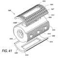
前記アセンブルされた装置は、円筒形に形作られ、その中央表面に沿ってネジ切りを有することにより、埋込片空洞の中への該装置のネジ式挿入を容易にする、項目1に記載の装置。
(項目16)
複合椎体間装置であって、該装置は、
上側端板であって、該上側端板は、
埋込部位の骨に接触するためのヒドロキシアパタイトによってコーティングされた多孔性の骨界面側面であって、該ヒドロキシアパタイトコーティングは、該骨界面側面上への骨成長を促し、該骨界面側面の細孔は、該骨界面側面の中への骨成長を可能にする、骨界面側面と、
該骨界面側面と反対側の多孔性のコア界面側面と、
該コア界面側面と該骨界面側面との間の中心障壁層と、
該上側端板を通る少なくとも1つの開口と
を有する、上側端板と、
下側端板であって、該下側端板は、
該埋込部位の骨に接触するためのヒドロキシアパタイトによってコーティングされた多孔性の骨界面側面であって、該ヒドロキシアパタイトコーティングは、該下側端板の骨界面側面上への骨成長を促し、該下側端板の骨界面側面の細孔は、該下側端板の骨界面側面の中への骨成長を可能にする、骨界面側面と、
該骨界面側面と反対側の多孔性のコア界面側面と、
該コア界面側面と該骨界面側面との間の中心障壁層と、
該下側端板を通る少なくとも1つの開口と
を有する、下側端板と、
該上側と下側端板との間のプラスチックコアであって、該コアは、
該上側端板のコア界面側面の細孔と接着され、貫通する上側表面と、
該下側端板のコア界面側面の細孔と接着され、貫通する下側表面と、
該コアを通る少なくとも1つのチャネルであって、該複合椎体間装置を通る骨成長を可能にするために、該上側コア表面における上側端板開口および該下側コア表面における下側端板開口と整列させられる少なくとも1つのチャネルと
を有する、プラスチックコアと
を含む、装置。
(項目17)
前記上側端板および前記下側端板の前記中心障壁層は、チタンの中実シートを含み、
該上側端板および該下側端板の前記骨界面側面は、チタンメッシュの少なくとも1つの層を含み、該メッシュにおける開口部は、前記骨界面細孔を提供し、
該上側端板および該下側端板の前記コア界面側面は、チタンメッシュの少なくとも1つの層を含み、該メッシュにおける開口部は、前記コア界面細孔を提供し、
該骨界面細孔は、該コア界面細孔よりも小さいことにより、骨内部成長のために該骨界面細孔を最適化する一方、該コア界面側面の流動制限を低減させることにより、該コア界面細孔の中への前記コア材料の流動を促進し、該中心障壁層は、該コア材料が該骨界面細孔の中へと流動し、遮断することを防止する、項目16に記載の装置。
(項目18)
前記上側端板および前記下側端板の前記中心障壁層は、チタンの中実シートを含み、
該上側端板および該下側端板の前記骨界面側面は、穿孔されたチタンの少なくとも1つの層を含み、該金属における穿孔は、前記骨界面細孔を提供し、
該上側端板および該下側端板の前記コア界面側面は、穿孔されたチタンの少なくとも1つの層を含み、該チタンにおける穿孔は、前記コア界面細孔を提供し、
該骨界面細孔は、該コア界面細孔よりも小さいことにより、骨内部成長のために該骨界面細孔を最適化する一方、該コア界面側面の流動制限を低減させることにより、該コア界面細孔の中への前記コア材料の流動を促進し、該中心障壁層は、該コア材料が該骨界面細孔の中に流入し、遮蔽することを防止する、項目16に記載の装置。
(項目19)
複合椎体間装置であって、
上側および下側表面と、コアを通る骨成長を可能にするための1つ以上の特徴とを有するプラスチックコアと、
該上側コア表面とともに構成されるコア界面側面と、埋込部位の骨と接合するための該コア界面側面と反対側の骨界面側面とを含む上側端板であって、該骨界面側面は、ヒドロキシアパタイトによってコーティングされ、該骨界面側面の表面積を増加させるために、複数の微小機械加工された表面特徴を有することにより、骨と該骨界面側面との間の接着を向上させる、上側端板と、
該下側コア表面とともに構成されるコア界面側面と、埋込部位の骨と接合するための該コア界面側面と反対側の骨界面側面とを含む下側端板であって、該骨界面側面は、ヒドロキシアパタイトによってコーティングされ、該骨界面側面の表面積を増加させるために、複数の微小機械加工された表面特徴を有することにより、骨と該骨界面側面との間の接着を向上させる、下側端板と
を含む、装置。
(項目20)
前記アセンブルされた装置の形状は、インゲン豆形状、円筒形、および弾丸形状から成る群から選択される、項目19に記載の装置。
(項目21)
前記装置は、円筒形に形作られ、前記微小機械加工された表面特徴は、埋込片空洞の中への該装置のネジ式挿入を促進するためのネジ切りを含む、項目19に記載の装置。
(項目22)
複合椎体間装置を製造する方法であって、該方法は、
上側および下側端板をアセンブルするステップであって、
骨界面層の骨界面側面の反対側で、該骨界面層の上に中実の中心障壁層を形成するステップと、
該骨界面層の反対側で、該中心障壁層の上に多孔性のコア界面層を形成するステップと
を含む、ステップと、
該下側および上側端板を鋳型の中で、コア空洞の各側面に1つずつ定置するステップであって、該コア界面層は、該コア空洞に対面し、および該骨界面側面は、該空洞から離れる方向に対面する、ステップと、
溶融プラスチックを該コア空洞の中に射出成形することにより、該端板間において、該コア界面層のコア界面側面と接着されるプラスチックコアを形成するステップであって、溶融プラスチックが、該コア界面層の細孔の中に押し出されて、該端板と接着する、ステップと
を含む、方法。
(項目23)
前記端板をアセンブルするステップは、
チタンワイヤメッシュの少なくとも2つのシートを選択的にともに定置するステップによって、前記骨界面層を形成するステップであって、それにより、該メッシュにおける開口部が、相互に対して所望の構成を形成し、該開口部は、該骨界面層の中に細孔を形成する、ステップと、
前記コア界面層を前記中心障壁層および該骨界面層と拡散接合するステップと、
前記拡散接合されたアセンブリから、各端板を形作るステップと
をさらに含み、
前記多孔性のコア界面層を形成するステップは、該中心障壁層の役割を果たす中実のチタンシートの上に、より大きい織目のまたはより大きいゲージのチタンワイヤメッシュの少なくとも1つのシートを定置するステップを含み、
前記上側端板および前記下側端板の前記中心障壁層は、前記溶融プラスチックが、該骨界面層の細孔の中に過剰に押し出されることを防止して、骨内部成長のための該骨界面細孔を留保し、
該上側および下側端板の前記骨界面側面をヒドロキシアパタイトによってコーティングするステップをさらに含む、項目22に記載の方法。
(項目24)
前記上側端板、前記コア、および前記下側端板を通る少なくとも1つのチャネルを作製するステップをさらに含み、それにより、前記椎体間装置を通る骨成長を提供する、項目23に記載の方法。
(項目25)
前記骨界面層の上に前記中心障壁層を形成するステップは、穿孔されたチタンの少なくとも1つのシートの上に中実のチタンシートをアセンブルするステップを含み、前記多孔性のコア界面層を形成するステップは、該骨界面層の反対側の該中心障壁層の上に、該骨界面層よりも大きい穿孔を有する、穿孔されたチタンの少なくとも1つのシートを定置するステップを含み、
前記コア界面層を該中心障壁層および該骨界面層と拡散接合するステップと、
前記拡散接合されたアセンブリから、各端板を形作るステップと、
をさらに含み、
前記上側端板および前記下側端板の前記中心障壁層は、前記溶融プラスチックが、該コア界面層の中の穿孔を通って、該骨界面層の穿孔の中に過剰に押し出されることを防止し、骨内部成長のための骨界面穿孔を留保する、項目23に記載の方法。
(項目26)
前記上側および下側端板の前記骨界面側面をヒドロキシアパタイトによってコーティングするステップをさらに含む、項目25に記載の方法。
(項目27)
前記中実の中心障壁層および前記骨界面層を形成するステップは、未加工側面と複数の機械加工された表面特徴を有する側面とを有する単一のチタンシートを提供するステップを含み、該未加工側面は、中心障壁層としての役割を果たし、該特徴付けられた側面は、該骨界面層を形成し、該表面特徴は、該骨界面層の表面積を増加させて、埋込部位における骨との接触を最適化し、該中心障壁層の反対側の側面において、該骨界面層をヒドロキシアパタイトによってコーティングするステップをさらに含む、項目22に記載の方法。
(項目28)
椎体間装置を向上させるための方法であって、
多孔性の骨界面表面を有する上側端板を、該骨界面表面の反対の側面において、該装置の上側表面と接着するステップと、
多孔性の骨界面表面を有する下側端板を、該骨界面表面の反対の側面において、該装置の下側表面と接着するステップと
を含み、
該端板を該装置と接着するステップは、複合コーティングとして、該端板を該椎体間装置に適用するステップを含む、方法。In another embodiment, a method of manufacturing a composite interbody device includes upper and lower endplates by forming a solid central barrier layer on a bone interface layer opposite the bone interface side of the bone interface layer. Assembling. The porous core interface layer is formed on the central barrier layer opposite the bone interface layer. The lower and upper endplates are placed in a mold, and on both sides of the core cavity, the core interface layer faces the core cavity and the bone interface side faces outward from the cavity. The molten plastic is injection molded into the core cavity to form a plastic core between the end plates and bonded to the core interface side of the core interface layer. The molten plastic is extruded into the pores of the core interface layer and adheres to the end plate.
For example, the present invention provides the following items.
(Item 1)
A compound interbody device,
A plastic core having upper and lower surfaces, the core having one or more features to allow bone growth through the core;
A metal upper end plate having a core interface side surface coupled to the upper surface, wherein the metal upper end plate is opposite to the core interface side surface to join the bone at the implantation site. A metallic upper endplate having a plurality of bone interface pores to allow bone growth therein;
A metal lower end plate having a core interface side surface coupled to the lower surface, wherein the metal lower end plate is opposite to the core interface side surface for joining with bone at an implantation site A metal lower endplate having a plurality of bone interface pores to allow bone growth therein;
A hydroxyapatite coating applied to the bone interface sides of the upper and lower endplates to promote bone growth on the endplates;
Including the device.
(Item 2)
The apparatus of item 1, wherein the upper and lower end plates comprise titanium.
(Item 3)
The core feature includes a vertically oriented channel through the core, and the lower and upper end plates each pass through the end plate to allow vertical bone growth through the interbody device. The apparatus of claim 1, comprising an opening leading into the vertically oriented core channel.
(Item 4)
The core interface side of the lower end plate and the core interface side of the upper end plate include at least one layer of titanium wire mesh, the mesh comprising a plurality of core interface cells for receiving material from the plastic core. The apparatus of item 1, wherein holes are provided to improve adhesion between the core and the upper and lower end plates.
(Item 5)
The bone interface side surface of the lower end plate and the bone interface side surface of the upper end plate include one or more layers of titanium wire mesh that provide the bone interface side pores, the bone interface pores comprising the core Item 5. The device according to Item 4, wherein the device is smaller than the interface pore.
(Item 6)
The upper end plate and the lower end plate each have excess molten core material in the bone interface pores when the core is injection molded between the upper end plate and the lower end plate. 6. The device of item 5, comprising a central barrier layer between the core interface side and the bone interface side to prevent extrusion.
(Item 7)
6. The device of item 5, wherein the bone interface pore is about 600 micrometers.
(Item 8)
The apparatus of claim 6, wherein the central barrier layer comprises a titanium sheet.
(Item 9)
The core interface side and the bone interface side of the upper and lower endplates comprise perforated metal sheets;
The perforation on the bone interface side forms the bone interface pores;
The perforations on the side of the core interface are larger than the bone interface pores, and the core interface perforations cause the molten material of the core to enter the core interface perforations when the core is molded between the end plates. The apparatus of claim 1, wherein the apparatus is flowed to improve adhesion of the core to the upper and lower end plates.
(Item 10)
(Item 11)
A central barrier layer is further included between the core interface side surface and the bone interface side surface so that when the core is injection molded between the end plates, the molten core material is in the upper side and
(Item 12)
The upper and lower end plates each include a central barrier layer between the bone interface side surface and the core interface side surface, and the bone interface side surface, the core interface side surface, and the central barrier layer are both diffusion bonded. The apparatus according to item 1, wherein the upper or lower end plate is formed.
(Item 13)
The apparatus of claim 1, wherein the upper and lower end plates are shaped to conform to one or both of (a) the shape of the core and (b) the shape of the bone contacting surface at the implantation site.
(Item 14)
The apparatus of item 1, wherein the assembled device shape is selected from the group consisting of a kidney bean shape, a cylindrical shape, and a bullet shape.
(Item 15)
The assembled device of claim 1, wherein the assembled device is cylindrically shaped and has threading along its central surface to facilitate threaded insertion of the device into an implant cavity. apparatus.
(Item 16)
A compound interbody device, the device comprising:
An upper end plate, the upper end plate
A porous bone interface side coated with hydroxyapatite for contacting the bone at the implantation site, the hydroxyapatite coating promoting bone growth on the bone interface side and A hole that allows bone growth into the bone interface side;
A porous core interface side opposite to the bone interface side;
A central barrier layer between the core interface side and the bone interface side;
At least one opening through the upper end plate;
An upper end plate,
A lower end plate, the lower end plate
A porous bone interface side coated with hydroxyapatite for contacting bone at the implantation site, wherein the hydroxyapatite coating promotes bone growth on the bone interface side of the lower endplate; The bone interface side pores of the lower end plate allow bone growth into the bone interface side of the lower end plate;
A porous core interface side opposite to the bone interface side;
A central barrier layer between the core interface side and the bone interface side;
At least one opening through the lower end plate;
A lower end plate, and
A plastic core between the upper and lower endplates, the core comprising:
An upper surface bonded to and penetrating the pores on the side of the core interface of the upper end plate;
A lower surface that is bonded to and penetrates the pores on the side of the core interface of the lower end plate;
At least one channel through the core, the upper end plate opening at the upper core surface and the lower end plate opening at the lower core surface to allow bone growth through the composite interbody device At least one channel aligned with
Having a plastic core and
Including the device.
(Item 17)
The central barrier layer of the upper end plate and the lower end plate includes a solid sheet of titanium;
The bone interface sides of the upper end plate and the lower end plate include at least one layer of titanium mesh, the openings in the mesh provide the bone interface pores;
The core interface sides of the upper end plate and the lower end plate include at least one layer of titanium mesh, the openings in the mesh provide the core interface pores;
The bone interface pores are smaller than the core interface pores, thereby optimizing the bone interface pores for bone ingrowth while reducing flow limitations on the side surfaces of the
(Item 18)
The central barrier layer of the upper end plate and the lower end plate includes a solid sheet of titanium;
The bone interface sides of the upper end plate and the lower end plate include at least one layer of perforated titanium, the perforations in the metal providing the bone interface pores;
The core interface sides of the upper end plate and the lower end plate include at least one layer of perforated titanium, the perforations in the titanium providing the core interface pores;
The bone interface pores are smaller than the core interface pores, thereby optimizing the bone interface pores for bone ingrowth while reducing flow limitations on the side surfaces of the
(Item 19)
A compound interbody device,
A plastic core having upper and lower surfaces and one or more features to allow bone growth through the core;
An upper end plate comprising a core interface side surface configured with the upper core surface and a bone interface side surface opposite to the core interface side surface for joining with bone at an implantation site, the bone interface side surface comprising: Upper end plate coated with hydroxyapatite and having a plurality of micromachined surface features to increase the surface area of the bone interface side surface, thereby improving the adhesion between the bone and the bone interface side surface When,
A lower end plate comprising a core interface side surface configured together with the lower core surface and a bone interface side surface opposite to the core interface side surface for joining to a bone at an implantation site, Is coated with hydroxyapatite and has a plurality of micromachined surface features to increase the surface area of the bone interface side, thereby improving adhesion between the bone and the bone interface side. With side end plate
Including the device.
(Item 20)
Item 20. The device of item 19, wherein the assembled device shape is selected from the group consisting of a kidney bean shape, a cylindrical shape, and a bullet shape.
(Item 21)
The apparatus of item 19, wherein the apparatus is cylindrically shaped and the micromachined surface features include threading to facilitate threaded insertion of the apparatus into an implant cavity. .
(Item 22)
A method of manufacturing a composite interbody device, the method comprising:
Assembling the upper and lower end plates,
Forming a solid central barrier layer over the bone interface layer on the opposite side of the bone interface side of the bone interface layer;
Forming a porous core interface layer on the central barrier layer opposite the bone interface layer;
Including steps, and
Placing the lower and upper endplates in a mold, one on each side of the core cavity, the core interface layer facing the core cavity, and the bone interface side Facing in a direction away from the cavity,
Forming a plastic core between the end plates by bonding the molten plastic into the core cavity, wherein the molten plastic is bonded to the core interface side surface of the core interface layer. Extruding into the pores of the layer and adhering to the end plate; and
Including a method.
(Item 23)
Assembling the end plate comprises the steps of:
Forming the bone interface layer by selectively placing together at least two sheets of titanium wire mesh, whereby the openings in the mesh form a desired configuration relative to each other. The opening forms pores in the bone interface layer; and
Diffusion bonding the core interface layer with the central barrier layer and the bone interface layer;
Forming each end plate from the diffusion bonded assembly;
Further including
The step of forming the porous core interface layer comprises placing at least one sheet of a larger texture or larger gauge titanium wire mesh on a solid titanium sheet that serves as the central barrier layer. Including the steps of
The central barrier layer of the upper end plate and the lower end plate prevents the molten plastic from being pushed excessively into the pores of the bone interface layer, and the bone for bone ingrowth. Retain the interfacial pores,
24. The method of
(Item 24)
24. The method of item 23, further comprising creating at least one channel through the upper end plate, the core, and the lower end plate, thereby providing bone growth through the interbody device. .
(Item 25)
Forming the central barrier layer on the bone interface layer includes assembling a solid titanium sheet on at least one sheet of perforated titanium to form the porous core interface layer Positioning comprises placing at least one sheet of perforated titanium having a perforation larger than the bone interface layer on the central barrier layer opposite the bone interface layer;
Diffusion bonding the core interface layer with the central barrier layer and the bone interface layer;
Forming each end plate from the diffusion bonded assembly;
Further including
The central barrier layer of the upper end plate and the lower end plate prevents the molten plastic from being excessively pushed through the perforations in the core interface layer and into the perforations of the bone interface layer. 24. The method of item 23, wherein the bone interface perforation for bone ingrowth is retained.
(Item 26)
26. The method of item 25, further comprising coating the bone interface side of the upper and lower endplates with hydroxyapatite.
(Item 27)
Forming the solid central barrier layer and the bone interface layer includes providing a single titanium sheet having a raw side surface and a side surface having a plurality of machined surface features. The processed side serves as a central barrier layer, the characterized side forms the bone interface layer, and the surface features increase the surface area of the bone interface layer to increase the bone at the implantation site. 23. The method according to
(Item 28)
A method for improving an interbody device, comprising:
Adhering an upper end plate having a porous bone interface surface to the upper surface of the device on the opposite side of the bone interface surface;
Adhering a lower endplate having a porous bone interface surface to the lower surface of the device on the opposite side of the bone interface surface;
Including
The method of adhering the end plate to the device comprises applying the end plate to the interbody device as a composite coating.
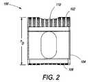
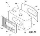
図1は、コア104の側面に位置する上側端板102および下側端板106を含む複合椎体間装置100を示す。コア104は、例えば、装置100を通る骨成長を促すために、および/または骨および任意の関連した成長向上剤等の固定向上材料または固定向上接合用接着剤を格納するための、コア104を通るチャネル等の1つ以上の特徴108を有するPEEKコア(すなわち、射出成形された熱硬化性PEEKプラスチック)である。コア104は、代替として、所望の形状に形成するために十分に可鍛性であるが、意図された埋込部位の耐久性要件を満たすために十分に強固である任意の他の生体適合性材料からできていてもよい。特徴108は、コア104が射出成形された後に、機械加工されてもよく、または、特徴108は、押出成形または別様に形成されてもよい。特徴108Aは、端板102および106がコア104と組み合わされると、上側端板102内の開口110および下側端板106を通る開口112と整列する、コア104を通って上面から底面まで貫通する、垂直に配向されたチャネルである。開口110、チャネル108A、および開口112をともに整列させることによって、装置100全体を通る骨成長を可能にする通路を形成する。PEEKは放射線透過性であるので、コア104は、埋込の間またはその後に、X線においてコア104の可視化を促進するための1つ以上の放射線マーカ114を含んでもよい。 FIG. 1 shows a
特徴108Bは、コア102の両側面における水平に配向された開口または孔、あるいは代替として、コア104を通る側面から側面まで貫通するチャネルである。特徴108C(図2に標識される)は、コア104の背面における水平に配向された開口または孔(椎骨間に挿入されると、脊髄の遠位に来る)、あるいは代替として、コア104を通って背面から正面まで貫通するチャネルである。一実施形態において、特徴108Bおよび108Cは、垂直に配向されたチャネル108Aの中に通じており、したがって、チャネル108または端板開口110および112を通る垂直骨成長に加え、装置100の両側面および背面を通る骨成長を可能にする。特徴108A−Cは、コア104が成形された後(例えば、端板102と106との間に、コア104を射出成形した後)に、機械加工することによって作製されてもよい。代替として、特徴108A−Cは、装置100を形成するための鋳型内に定置される1つ以上の取外し可能なマンドレルを使用して、装置100の中へと成形されてもよい。 Feature 108B is a horizontally oriented opening or hole on either side of
示されるように、端板102/106は、以下の図3に関連してさらに説明されるように、受容する骨表面に適合するように湾曲している。コア104が、端板102と106との間に成形されると、装置100は、例えば、埋込部位内への挿入を容易にする弾丸形状をとる。端板102および106は、意図された用途(すなわち、装置100の意図された埋込部位または意図された最終形状)に応じて、直線であるか、湾曲しているか、角度が付けられるか、または別様に形作られてもよいことを理解されるであろう。端板102および106が、例えば、プレス機内において拡散接合され、所望の形状および/または輪郭を達成する。 As shown, the
端板102/106は、例えば、ヒドロキシアパタイト(HA)でコーティングされる多孔性チタンであって、(多孔性端板上への)骨表面成長および(端板の細孔内への)内部成長の両方を促す。PEEKコアを直接ではなく、チタン製端板をHAでコーティングすることによって、コア104の強度および靭性を犠牲にすることなく、生物活性(例えば、骨成長)を助長する。チタンは、HAと接着する生体適合性材料であって、したがって、端板102および104によって骨表面成長を促進する。チタン製のHAコーティングされた端板は、HAがPEEKの中に直接混入されるときに生じるようなPEEKコアの強度低下を起こすことなく、強度、生体適合性、および表面成長を提供する(PEEK破壊靭性は、HAの直接適用によって劣化させられることが知られている)。加えて、装置100のチタン−PEEK−チタンの組み合わせは、主にチタン製の埋込片のより強固な靭性を回避し、それによって、骨成長および骨固定を阻害するストレスシールディング(stress shielding)を低減させる。モリブデン、コバルト・クロム、ステンレス鋼、および他の生体適合性合金等の、他の生体適合性金属も、端板102および106を形成する際等に、チタンの代わりに、またはそれに加え、使用されてもよいことを理解されるであろう。例えば、他の生体適合性金属は、端板102および106を形成するためのチタンと合金化されてもよい。
図2は、装置100の背面図であって、コア104とともに構成された端板102および106を特徴付け、後側特徴108Cを示す。後側特徴108Cは、幅約4mm×高さ3−6mmの寸法を有するコア104内の開口である。コア104の後端を通る骨成長を可能にすることに加え、特徴108Cは、特徴108Cに嵌着するように定寸されたツールの使用によって埋込部位への装置100の定置を容易にする。 FIG. 2 is a rear view of the
一側面において、端板102および106を含む装置100の高さ(hD)は、約12mmから約17.1mmまでの範囲である。チャネル108Aと整列させられると、上側端板102の開口110および下側端板106の開口112は、また、少なくとも特徴108Cを介してもアクセス可能であるコア104内の共通空間内に通じていてもよい。In one aspect, the height (hD ) of
図3は、アセンブルされた装置100の側面図である。一側面において、装置100は、装置100/コア104の長さ(lD)の少なくとも一部に及ぶ、上側および下側の端板接触表面116および118を含む。長さlDは、例えば、約26mmである。端板102/106は、接触表面116および118の形状と適合するように湾曲している。図3には図示されないが、端板102および106はまた、意図された挿入部位の骨表面に適合またはそれと最適に相互作用するように、端板接触表面と反対の骨界面側面126に形作られてもよいことを理解されるであろう。コア104は、先端面取り部線120から開始して前端122まで面取りされ、隣接する椎骨等、骨表面間への挿入を促進してもよい。装置100は、例えば、前端が、最初に、挿入矢印124によって示される方向に、椎骨間に挿入される。端板102/106は、約1−2mmの端板高さ(hE)を有する。端板102/106は、コア104とのアセンブリングの前または後に、ヒドロキシアパタイトによってコーティングされてもよい。一実施例において、端板102/106は、鋳型内への定置に先立って、ヒドロキシアパタイトでスプレーコーティングされ、コア104は、端板102/106間に射出成形される。FIG. 3 is a side view of the assembled
図4は、装置100の簡略化された上面図であって、図5−8に関連してさらに説明される上側端板102の骨界面側面126を示す。以下の説明を読めば、図4はまた、下側端板106の骨界面側面を表し得ることを理解されるであろう。 FIG. 4 is a simplified top view of the
図4−8による実施形態において、装置100の幅(wD)は、約11mmである。端板102の開口110は、開口長さ(lA)約13−14mmおよび開口幅(WA)約5−6mm(図4)を有する。端板102は、上側端板長さ(lES)約22−23mm(図5)を有する。端板102の骨界面側面126は、例えば、装置100が埋め込まれると、その中に骨が成長し得る複数の孔または細孔127を含む、HAでコーティングされたチタン、モリブデン、または他の生体適合性金属である。骨界面側面126は、コア界面側面128(図6)と反対側にある。コア界面側面128は、コア104に面し、コア104の材料を受容して、コア104への付着を向上させるために、複数の孔または細孔129を含む。骨界面側面126の細孔127は、骨内部成長を助長するための最適サイズである。例えば、細孔127は、直径約600マイクロメートルである。コア界面側面128の細孔129は、骨界面側面126の細孔127より大きく、コア104と端板102との間の接着を最大にする。端板102と104との間に射出成形されると、コア104の材料は、より大きい細孔129を介してコア界面側面128に侵入し、端板102をコア104としっかり接着する。細孔127および129は、それぞれ、側面126および128を通した穿孔または孔であってもよく、または細孔127および129は、側面126および128を形成する、ワイヤメッシュ内の開口部であってもよい。細孔、穿孔、および開口部という用語は、以下、互換可能に使用される。In the embodiment according to FIGS. 4-8, the width (wD ) of the
上側端板102および下側端板106は、挿入を容易にするために湾曲させられるか、または別様に形作られる。しかしながら、端板102および106は、代替として、装置100と隣接する骨との間の接触を最大にするように形作られてもよい(例えば、端板骨界面側面126は、端板102/106と隣接する骨との間の表面積接触を最大にするように平坦化されてもよい)。図1、3、8、および12に示されるように、端板102および106は、埋込部位において、受容する椎骨表面と嵌合するように湾曲させられる。したがって、装置100の形状は、椎間空間を模倣する。装置100、端板102/106および/またはコア104の形状およびサイズは、異なって定寸され、形作られる埋込部位に適合するように改変されてもよい。装置100は、埋込部位を調製するために使用される切削ツールによって、生成される空洞を模倣するように形作られてもよい。例えば、装置100は、臀部、膝、または肩関節における固定を促進するために、ボールミルによって拡開された空洞を模倣するように形作られてもよい。
図9−12は、下側端板106の付加的な詳細であって、以下の説明とともに閲覧されるのが最適である。端板102と同様に、端板106は、細孔127(例えば、約600マイクロメートル)を有する骨界面側面126と、コア104材料を受容するために比較的により大きい細孔129を有するコア界面側面128とを有する。骨界面側面126は、ヒドロキシアパタイトによってコーティングされたチタン、モリブデン、または他の生体適合性金属であってもよい。開口112は、成形後に機械加工することによって作製されてもよく、例えば、上側端板102の開口110に類似する寸法を有するコア104の垂直に配向されたチャネル108Aにアクセス可能にするように定寸される。端板106は、下側端板長さ(lEI)約21−22mmを有する端板102よりも若干短くてもよい。端板102/106は、例えば、次いで、所望に応じて形作られる複数の端板に切断されるコア界面側面128材料によって補強された骨界面側面126の材料の大型シートから加工される。例えば、コア界面側面126の材料および骨界面側面128の材料のシートは、端板102/106を形成するために、予め接着され、所望のサイズに切断されてもよい。次いで、切断部は、熱および圧力下において、分子レベルで側面126の材料を側面128の材料と恒久的に接続するように拡散接合されてもよい。端板102/106は、拡散接合の際、またはそれに先立って、所望に応じて、湾曲させられるか、または別様に形作られてもよい。後述のように、端板アセンブリ200(図19)に対して、中心障壁層は、側面126材料と側面128材料との間に挿入され、コア界面側面128の細孔129に侵入するコア材料が、側面126の細孔127によって提供される骨内部成長領域に浸透またはそれを塞栓することを防止する。FIGS. 9-12 are additional details of the
図13は、端板102/106の骨界面側面126の上面図であって、図14は、側面126の区画Aの付加的詳細を示す。一実施形態において、骨界面側面126は、チタンの薄いシートであって、細孔127は、骨界面側面126を通して穿孔される。穿孔127は、直径約0.30mmと、所与の横列130または132に沿った中心間間隔約0.050mmとを有する。例えば、横列132における穿孔127Aの中心から穿孔127Bの中心までの距離は、約0.30mmである。隣接する横列130および132の穿孔127は、横列132内の穿孔127Aと横列130内の穿孔127Cとの間の中心間(対角)距離が、約0.030−0.045mmであるように、オフセットされる。穿孔127は、骨界面側面126の縁から、約0.030−0.040mmの所から開始してもよい。 FIG. 13 is a top view of the
図15−18に例示されるように、一実施形態において、コア界面側面128の細孔129は、チタンまたは他の金属の薄いシートを通して穿孔される。穿孔129は、コア104が端板102/106のコア界面側面128間に射出成形されるとき、コア104の材料を受容するように最適化される。穿孔129は、細孔127より大きく、楕円から長方形までの形状であってもよい。一側面において、穿孔129は、幅(wP)約0.050mmおよび長さ(lP)約0.100mmを有する。穿孔129は、例えば、側面128の縁から約0.050mmの間隔をあけて配置され、隣接する穿孔は、約0.010mm離れて配置される。As illustrated in FIGS. 15-18, in one embodiment, the
図17は、図15の線17−−17に沿った、側面128の断面図である。図18は、図17の区画Bの拡大図であって、穿孔129の側面図を示す。 FIG. 17 is a cross-sectional view of
図19は、前述の椎体間装置100の端板102および/または端板106を形成するためのアセンブリ200の分解図である。図20は、アセンブリ200の骨界面側面図を例示する。図21は、図20の線21−−21に沿った断面図であって、図22は、図21の部分Cの拡大図であって、アセンブリ200の断面における付加的な詳細を示す。図19−22は、以下の説明とともに閲覧することが最適である。 FIG. 19 is an exploded view of an
図19−22による実施形態において、アセンブリ200は、少なくとも2つの骨界面層204および206を含む骨界面側面202を含む。第1および第2の骨界面層204および206が図19に示される。付加的な骨界面層(例えば、合計で4から5層の場合)が追加されることにより、側面202の骨内部成長の特性および/またはアセンブリ200から形成される端板102または106の引張強度または他の特性を変動させてもよい。 In the embodiment according to FIGS. 19-22, the
第1および第2の層204および206は、例えば、ヒドロキシアパタイトによってコーティングされて、骨表面成長を促し、骨内部成長のための最適サイズのチタンワイヤメッシュから形成される(例えば、メッシュは、約600マイクロメートルの直径の細孔208を提供する)。メッシュのワイヤは、例えば、0.5mmのチタンワイヤであって、コア界面側面210と比較して、比較的に低い空隙率および比較的に高い流動制限を提供する。細孔208は、代替として、正方形、長方形、または他の形状をとってもよく、それらは、短い寸法が約600マイクロメートル(例えば、長方形細孔の幅)と、短い寸法の約3倍以下の長い寸法(例えば、長方形細孔は、約1800マイクロメートル以下である)とを有する。 The first and
コア界面側面210は、骨界面側面202の反対側にあり、チタンまたは他の生体適合性金属の少なくとも1つのコア界面シート212を含む。シート212は、側面202の細孔208より大きい穿孔または細孔214を含み、アセンブリ200によって形成される端板と、コア104等の椎体間コアまたは人工椎間板等の別の椎体間装置との間の接着を最大にする。 The core interface side 210 is opposite the
コア界面シート212は、層204および206のメッシュより大きいゲージのワイヤ、またはより緩い織目のメッシュによって形成されるメッシュであって、側面202よりも比較的に大きい細孔、より高い空隙率、およびより低い流動制限を提供してもよい。より高い空隙率およびより低い流動制限は、椎体間コア/装置(すなわち、コア104材料)から、側面210の細孔214内への材料の流動を向上させて、アセンブリ200によって形成される端板(すなわち、端板102/106)とコア/装置との間の接着を促す。図19において、単一シート212が、コア界面側面210を構成するが、側面210は、より大きいゲージのチタンワイヤメッシュの複数のシート212を含んでもよいことを理解されるであろう。 The
代替として、側面210は、アセンブリ200によって形成される端板(例えば、端板10/106)と椎体間コア/装置との間の接着を促すように定寸された細孔を有する1つ以上の穿孔または微細エッチングされたコア界面シート212を含む。側面202(層204および206)と側面210(シート212)との間の中心プレートまたは層216は、椎体間コア/装置(例えば、コア104のPEEK)からの材料が、端板102/106の中に過剰に押し出されることを防止する。中心層216は、例えば、PEEKまたは他のコア104材料が、端板102/106まで流動することを防止し、プラスチックが骨界面層204および206の中に流動することを遮断し、したがって、細孔208によって提供される骨内部成長空間を維持する。 Alternatively, the side surface 210 has one pore sized to facilitate adhesion between the endplate formed by the assembly 200 (eg,
アセンブリ200は、層204、206、212、および216をダイの中へと定置して、熱および圧力を印加し、人工多孔性マトリクスを作製することによって拡散接合される。原子レベルにおける拡散接合は、相互に接触する表面の組み合わせを促進し、ほぼ100%の接着をもたらす。拡散接合は、アセンブリ200から、端板102/106を形成することに先立って生じてもよい。例えば、アセンブリ200は、50mm×25mm×0.75mmの複合シート(または、交互に定寸された複合シート)として形成されてもよく、端板102/106は、拡散接合後、アセンブリ200から切断されてもよい。代替として、端板102/106は、アセンブリ200から切断される(予め接着されてもよい)か、またはアセンブリ200は、拡散接合に先立って端板102/106の要件に定寸される。拡散接合は平坦シートを必要としないので、端板102/106の一方または両方の独特の曲率が対応させられる。曲率は、拡散接合のためのダイに組み込まれ、任意の椎体間装置/コア(コア104等)および/または任意の受容骨表面のために、端板102/106のカスタマイズを可能にしてもよい。例えば、端板202および206は、プレス機内において拡散接合され、所望の端板の形状または輪郭を産生してもよい。製造の間、端板102/106はまた、複数の定寸要件に適合するように、反映または調整されてもよい。 The
一実施形態において、二重アセンブリ200が、端板102および106のための定寸要件に従って定寸される。アセンブリ200は、コア材料(例えば、コア104材料、または端板102/106と接着するために構成される人工椎間板または別の椎体間装置を形成するための複数の材料)のための空洞に面するコア界面側面210とともに、鋳型内に位置付けられる。コア材料(例えば、PEEK)が、アセンブリ200間に射出成形され、コア界面側面210の細孔214に侵入してアセンブリ200(端板102/104)としっかり接着する。中心層216は、コア材料が、層204および206の細孔208の中に過剰に押し出されることを防止し、したがって、骨界面側面202の骨内部成長空間を保存する。図22に示されるように、層204および206の細孔208は、骨内部成長のための側面202を最適化するように選択的にオフセットされてもよい。 In one embodiment,
硬化されると、椎体間コア/装置(例えば、コア104)の形状および幾何学形状は、複合未加工物から機械加工されることによって精緻化されてもよい。例えば、特徴108は、成形後に、コア104に機械加工されてもよい(図1参照)。ヒドロキシアパタイトが、コア104が間に射出成形される前またはその後に、端板102/106の骨界面側面202上に表面処理されることにより、骨界面側面202上および中への骨表面成長ならびに内部成長を助長する。ヒドロキシアパタイトは、スプレーコーティング、適用、または別様に骨界面側面202に適用されてもよい。ヒドロキシアパタイトコーティングの深さは、最適な表面成長/内部成長効率を達成するために、または意図された埋込場所に従って、変動されてもよい。装置200の金属−PEEK−金属(例えば、チタン−PEEK−チタン)の組み合わせは、主にチタン製の埋込片より剛性が弱く、したがってストレスシールディングを低減させる。 Once cured, the shape and geometry of the interbody core / device (eg, core 104) may be refined by machining from the composite raw material. For example, the feature 108 may be machined into the
一実施形態において、穿孔および/またはテクスチャ加工によって形成されるチタンシートが、層204および206の一方または両方を形成するメッシュと置換される。層204および206は、選択的に、微細穿孔あるいはフォトエッチングされることにより、細孔208および/または他のテクスチャ加工特徴を提供してもよい。例えば、層202および204は、5mil(0.125mm)の分解能を有するフォトエッチングプロセスを使用して、500マイクロメートル(40−mil)穿孔/細孔208によってエッチングされる。したがって、側面202は、連続的に積層されたチタン穿孔/細孔208のマトリクスとして形成されてもよい。側面202上へのチタン穿孔/細孔208および側面210上へのより大きい細孔214の選択的定置は、骨内部成長およびPEEK接着の両方を調整/促進するための空隙率制御を可能にする。例えば、空隙率は、理想的な骨内部成長のために、約500−600マイクロメートルの細孔208を生成するように制御されてもよい。 In one embodiment, a titanium sheet formed by drilling and / or texturing is replaced with a mesh that forms one or both of
図23−26は、コア304の両側に位置する、機械で特徴付けられた上側および下側端板302および306を有する椎体間装置300を示す。コア304は、図1のコア104に類似してもよい。コア304は、コア104を通って上面から底面まで貫通する、垂直に配向されたチャネル308A、およびコア104を通って側面から側面まで貫通する、水平に配向されたチャネル308B等の複数の特徴308を含む。特徴308Aおよび308Bは、コア304/装置300を通る骨成長を促進し、骨および/または他の材料によって充填されることにより、固定を向上させてもよい(例えば、骨成長を向上させるためのタンパク質または他の材料、あるいは固定向上接合用接着剤)。コア304の背面におけるスロット308C(椎骨間に挿入されると、脊髄の遠位に来る)は、挿入ツールに嵌着し、隣接する椎骨間への装置300の挿入を容易にするように定寸される。特徴308A−Cは、コア304が成形された後(例えば、端板302と306との間にコア104を射出成形した後)に、機械加工されてもよく、あるいは特徴308A−308Cは、押出成形されるか、または別様に形成されてもよい。 FIGS. 23-26 illustrate an
チャネル308Aは、装置300が、図24に示されるようにアセンブルされると、上側端板302内の開口310および下側端板306内の開口312と整列する。装置300の中への挿入のための任意の固定補助は、開口310または開口312を介して装填され得ることが理解されるであろう。コア304が、PEEKプラスチック等の放射線透過性材料から形成される場合、1つ以上の放射線マーカ314が、例えば、装置300が埋め込まれるとき、X線におけるコア304の可視化を促進するように組み込まれてもよい。図25に示されるように、端板302は、コア304の上側端板接触表面316と接着し、端板306は、下側端板接触表面318と接着する。コア304は、先端面取り部線320から前端322までテーパ状になり、椎間空間または他の埋込部位内への装置300の挿入を容易にしてもよい。
端板302および306は、コア304および/または受容する骨表面の所望の形状に適合するように、プレス機内における形成および拡散接合の結果、湾曲させられる。一側面において、端板302および306は、そこから突出する幾何学形状特徴を有する多重表面の機械加工された陥凹チタンプレートであって、骨界面側面326(図25参照)上の骨表面成長のための相対的端板表面積を増加させる。リッジ313は、例示を容易にするために、図23−27に示される。しかしながら、リッジ313は、代表物に過ぎず、薄いウェブまたは他の幾何学形状で置換または代用されてもよいことが理解されるであろう。例えば、端板302および306は、チタンプレートを破砕する(すなわち、引き離す)ことから生じる幾何学形状特徴を担持してもよい。そのような端板は、有利なことに、1ステップ製造プロセスにおいて形成され、それによって、椎体間装置の全体的なコストを削減してもよい。 The
代替として、図示されないが、端板302および306のコア界面側面328もまた、コア界面側面328の表面積を増加させ、コア304材料との接着を向上させるための幾何学形状特徴を担持してもよい。代替として、シート212(図19参照)等の多孔性チタン層が、その反対側にリッジ313または他の特徴を有する単一チタンシートの背面(非特徴付けの)表面と拡散接合されてもよい。例えば、コア界面側面328は、骨界面側面326の背面表面と拡散接合されるチタンワイヤメッシュまたは穿孔されたチタンのシートを含んでもよい。そのような構成においては、中心障壁層は必要ない。 Alternatively, although not shown, the
図25に示される、装置300の長さ(lD300)および高さ(hD300)は、例えば、装置100(図2−3参照)の長さ(lD)および高さ(hD)に類似している。図26に示される装置300の幅(WD300)もまた、装置100の幅(WD)に類似してもよい。The length (lD300 ) and height (hD300 ) of the
図28は、椎体間装置400の分解斜視図であって、人工椎間板404に適用されるように、上側および下側端板402および406を形成する複合層を示す。一実施形態において、端板402および406はそれぞれ、一方の層が他方の層に相対的に、選択的に定置される骨界面層405および407を含み、層405および407の細孔または穿孔408によって提供される骨内部成長空間を最適化する。比較的により大きい細孔414(細孔408と比較して)を有する椎間板界面層412は、例えば、中実金属の薄いシートである中心障壁層416によって、層405および407から分離される。より大きい細孔416は、その中における人工椎間板404材料の流動を可能にする。例えば、椎間板404を形成する溶融または軟性プラスチックは、細孔414の中に押し出され、椎間板404と層412との間、したがって、椎間板404と端板402および406との間の接触および接着を最大にしてもよい。中心障壁層416は、椎間板404の材料が、細孔408の中に流入することを防止し、したがって、骨内部成長のための細孔408を留保する。 FIG. 28 is an exploded perspective view of the
骨界面層405および407、椎間板界面層412、ならびに中心障壁層416は、チタン等の生体適合性金属からできている。一実施形態において、骨界面層405および407は、小ゲージ(例えば、0.5mm)のチタンワイヤ間の空間によって形成される細孔408を有する、HAでコーティングされたチタンワイヤメッシュである。しかしながら、穿孔され、HAでコーティングされたチタンシートが、骨界面層405および407の一方または両方と置換されてもよい。中心障壁層416は、チタンの中実シートであって、コア界面層414は、骨界面層405および407より大きい細孔を有する、チタンメッシュのシートであって、人工椎間板404との接着を向上させる。 The bone interface layers 405 and 407, the intervertebral
端板402および406は、コア404の上側および下側端板接触表面417および418に、層毎に適用されてもよい。例えば、椎間板界面層412が、最初に、上側端板接触表面417に適用される。中心障壁層416は、層412に適用され、チタン/HA骨界面層407および405は、中心障壁層416に適用される。層405および407は、シート間の界面を最適化し、骨内部成長のための空隙率(すなわち、各層405、407の細孔408の整列)を最適化するように、選択的に定置されてもよい。図示されないが、層405および407自体がそれぞれ、チタンワイヤメッシュの複数の下位層(例えば、4−5の下位層)を含み、さらに低い空隙率を提供して、流動制限を上昇させてもよい。接触表面417および418は、人工椎間板404のPEEKプラスチック、チタン、コバルト・クロム、または合金表面であってもよく、その残りは、接触表面417および418と同一材料または代替材料から構成されてもよい。骨界面層405、407および中心障壁層416のいずれもが、相互にまたは椎間板界面層412に拡散接合されてもよい。人工椎間板404が、金属製接触表面417および418を含む場合、端板402および406の全層が、金属製接触表面に直接拡散接合されてもよい。
人工椎間板404はまた、椎体間装置100のコア104に関して前述のように、予めアセンブルされた端板402、406間に成形されてもよい。 The artificial
層405、407、416、および412は、随意に、それぞれの接触表面417および418を補完するように形作られる(すなわち、プレス機内での同時形成および拡散接合を介して)単一動作において上側端板接触表面417および下側端板接触表面418に適用される単一複合端板402/406に予形成されてもよい。層405、407、416、および412(または、そのから形成される端板402/406)の適用のために好適な一例示的椎間板は、PEEK椎間板上におけるPioneer NuBak PEEKである。端板402および406は、椎間板表面417および418の形状を補完するように形作られてもよく、または椎間板404は、端板の形状に適合する椎間板404によって、端板間に射出成形されてもよい。
図29は、装置100等の椎体間装置を形成するための一方法500を例示する。下側および上側端板が、ステップ502において、アセンブルされ、ステップ504において、コア空洞に面するコア界面層とともに鋳型内に定置される。コア材料が、ステップ506において、空洞の中へ、および空洞を介してコア界面側面の細孔の中に射出成形される。ステップ502−506の一実施例において、端板102および106は、図19に関連して説明されるようにアセンブルされる(アセンブリ200)。端板−コア−端板アセンブリが、ステップ508において、硬化させられ(例えば、アセンブリは、コアが完全に固化するまで、冷却されてもよい)、ステップ510において、鋳型から除去される。特徴が、ステップ512において、椎体間装置内に形成される。ステップ512の一実施例において、特徴108A−108Cならびに開口110および112は、装置100内に形成される。例えば、1つのチャネルが、装置100を通して穿通され、開口110、チャネル108A、および開口112を形成してもよい。装置の骨界面表面(すなわち、骨界面表面126、図3参照)が、ステップ514において、ヒドロキシアパタイトによってコーティングされる。図29において、最終ステップとして示されるが、ヒドロキシアパタイトは、代替として、または加えて、端板102および106の中へのその組み込みに先立って、あるいは端板の形成後、かつ鋳型内への定置に先立って、骨界面表面上にコーティングされてもよいことが理解されるであろう。 FIG. 29 illustrates one
図30は、椎体間装置を形成するための方法600を示す。方法600は、例えば、端板102および106を形成するために使用されるアセンブリ200等のアセンブリによって、装置100を形成するために使用される。中心障壁層が、ステップ602において、コア界面側面に形成され、骨界面側面が、ステップ604において、コア界面側面と反対側(例えば、それとは反対の側面)の中心障壁層に形成される。ステップ602−604の一実施例において、中心層216が、コア界面側面210上に定置され、骨界面側面202は、中心層216上に定置される(図19)。成形が必要とされる場合(決定606)、例えば、端板102および106等の端板が、側面202および210ならびに中心層216のより大きいアセンブリから切断されるべき場合、端板は、ステップ608において、アセンブリから形作られる。端板は、ステップ610において、拡散接合され、ステップ612において、空洞に対面するコア界面側面とともに鋳型内に定置される。ステップ606−612の一実施例において、端板102および106は、予め接着された側面202、中心層216、およびコア側面210のより大きいマスタシートから切断され、コア104を形成するために定寸および形作られた空洞を有する鋳型内への定置に先立って、熱および圧力下において拡散接合される。別の実施例において、側面202、中心層216、およびコア側面210のマスタシートは、端板102および106をマスタシートから切断または別様に成形することに先立って、拡散接合される。次いで、端板は、説明されたように鋳型内に定置される。 FIG. 30 shows a
ステップ614において、コア材料が、コア空洞内に射出成形され、コア界面側面の細孔の中に押し出される。成形されたアセンブリは、ステップ616において、固化するまで硬化され、ステップ618において、鋳型から除去される。端板および/またはコア特徴が、ステップ620において、固化した椎体間装置内に作製されてもよい。ステップ614−620の一実施例において、溶融PEEKプラスチック等のコア104材料は、コア空洞の中に射出成形され、穿孔または細孔214の中へと押し出される。中心障壁層216は、コア104材料が、側面202の細孔208の中へと押し出されることを防止し、したがって、骨内部成長空間としての細孔208を留保する。固化すると、開口110および112が、(それぞれ)上側および下側端板102および106に形成されてもよく、チャネル108A、チャネル108B、および開口108Cが、コア104に形成されてもよい。例えば、開口110および112ならびにチャネル108Aは、椎体間装置100を通して、単一穿通または他の機械加工動作において形成されてもよい。随意に、コア104のある特徴が、溶融PEEKプラスチックに通路を生成するために、1つ以上のマンドレルを有する特殊成形された鋳型を介して生成されてもよい。 In step 614, the core material is injection molded into the core cavity and extruded into pores on the side of the core interface. The molded assembly is cured until solidified at step 616 and removed from the mold at
図31は、装置100等の椎体間装置を形成する方法700を例示し、その端板は、アセンブリ200から形成されてもよい。ステップ702において、チタンワイヤメッシュが、選択的に積層されて、骨界面側面を形成する。中心障壁層が、ステップ704および706において、中実チタンシートから骨界面側面に形成され、コア界面層が、より大きい織目のチタンメッシュから中心障壁層上に形成される。ステップ704−706の一実施例において、骨界面側面202は、メッシュの開口部によって形成される細孔208が、一方の層の他方の層に対する配向が所望のものであるように、選択的にチタンワイヤメッシュ層204および206をともに定置することによって形成される。例えば、中実チタンシートである中心層216は、側面202とともに定置され、少なくとも1つのコア界面シート212が中心層216の反対側面とともに定置され、骨界面側面210を形成する。前述のように、シート214の細孔214は、細孔208より大きく、コア界面側面の流動制限を低減させる。 FIG. 31 illustrates a
骨界面側面、障壁層、およびコア界面側面(例えば、側面202、中心層216、および側面210)は、ステップ708において、ともに拡散接合される。成形が必要とされる場合(決定710)、端板(例えば、端板102および106)は、ステップ712において、骨界面側面障壁層/コア界面側面アセンブリから形作られ、随意に、ステップ714において、その骨界面側面がヒドロキシアパタイトによってコーティングされる。ステップ714は、ヒドロキシアパタイトコーティングが、方法700における他の点において、例えば、位置726または他の場所において生じてもよいことを示す、点線ボックスとして例示される。 The bone interface side, barrier layer, and core interface side (eg,
端板が、ステップ716において、コア空洞に対面するその骨界面側面とともに、鋳型の中に定置され、コア材料が、ステップ718において、端板間に射出成形され、コア界面側面における細孔(例えば、メッシュ開口部)の中に押し出される。硬化(ステップ720)後、椎体間装置が、ステップ722において、鋳型から除去され、端板および/またはコア特徴が、随意のステップ724において、作製される。ステップ716−724の一実施例において、端板102および106は、隣接する空洞に対面する側面210とともに鋳型の中に定置される。溶融コア104の材料(例えば、PEEKプラスチック)が、鋳型の中に射出され、細孔214に侵入させられる。PEEKが硬化させられた後、未加工の椎体間装置が、鋳型から除去され、開口110および112が、端板102ならびに106に形成され、104を成形する際に形成されなかった特徴108A−108Cのいずれかが、コア104に機械加工される。例えば、開口110、112およびチャネル108Aが、装置100を通して穿通されるように形成される。 An end plate is placed in the mold with its bone interface side facing the core cavity at step 716, and the core material is injection molded between the end plates at step 718 to provide pores (eg, Extruded into the mesh opening). After curing (step 720), the interbody device is removed from the mold at
骨界面側面(例えば、側面202)は、椎体間装置が、その所望の特徴とともに機械加工された後、端板が、骨界面側面障壁層/コア界面側面アセンブリから形作られた後、または両方において、ヒドロキシアパタイトによってコーティングされる。代替として、骨界面側面を形成するメッシュ層が、層をともに定置して骨界面側面を形成することに先立って、ヒドロキシアパタイトによってコーティングされてもよく、または骨界面側面が、中心障壁層とのその定置に先立って、ヒドロキシアパタイトによってコーティングされてもよい。ヒドロキシアパタイトコーティングの深さおよび配置は、意図された埋込部位の関数として変動してもよい。 The bone interface side surface (eg, side surface 202) can be used after the interbody device has been machined with its desired characteristics, after the endplate has been formed from the bone interface side barrier layer / core interface side assembly, or both. And coated with hydroxyapatite. Alternatively, the mesh layer forming the bone interface side may be coated with hydroxyapatite prior to placing the layers together to form the bone interface side, or the bone interface side may be coated with the central barrier layer. Prior to its placement, it may be coated with hydroxyapatite. The depth and placement of the hydroxyapatite coating may vary as a function of the intended implantation site.
図32は、椎体間装置を形成する方法800を例示する。方法800は、端板102および106を作製するためのアセンブリ200を使用して、装置100を形成するために使用されてもよい。骨界面側面は、ステップ802において、穿孔されたチタンの少なくとも1つのシートから形成され、チタンの中実シートから形成される中心障壁層は、ステップ804において、骨界面側面に定置される。コア界面側面は、ステップ806において、骨界面層と反対側の中心障壁層上に形成される。ステップ802−806の一実施例において、骨界面側面202は、穿孔が一方の層の他方の層に対する配向が所望のものであるように、選択的に、複数の穿孔されたチタンシートをともに定置することによって形成される。また、穿孔127を有する、穿孔された骨界面側面126を示す、図5−8も参照されたい。 FIG. 32 illustrates a
例えば、中実チタンシートである中心層216は、側面202とともに定置され、少なくとも穿孔されたチタンシート212は、中心層216の反対側面とともに定置され、骨界面側面210を形成する。シート212の穿孔214は、穿孔208より大きく、コア界面側面における流動制限を低減させる。 For example, a
骨界面側面、障壁層、およびコア界面側面(例えば、側面202、中心層216、および側面210)が、ステップ808において、ともに拡散接合される。成形が必要とされる場合(決定810)、端板(例えば、端板102および106)は、ステップ812において、骨界面側面/障壁層/コア界面側面アセンブリから形作られ、随意に、ステップ814において、その骨界面側面がヒドロキシアパタイトによってコーティングされる。ステップ814は、ヒドロキシアパタイトコーティングが、方法700における他の点において、例えば、位置826または他の場所において、生じてもよいことを示すように、点線ボックスとして例示される。 The bone interface side, barrier layer, and core interface side (eg,
端板が、ステップ816において、コア空洞に対面するその骨界面側面とともに、鋳型の中に定置され、コア材料が、ステップ818において、端板間に射出成形され、コア界面側面における細孔(例えば、メッシュ開口部)の中へと押し出される。硬化(ステップ820)後、椎体間装置が、ステップ822において、鋳型から除去され、端板および/またはコア特徴が、随意のステップ824において、作製される。骨界面側面は、未だコーティングされていない場合、または付加的コーティングが所望される場合、ステップ826において、ヒドロキシアパタイトによってコーティングされる。ステップ816−826は、前述で詳述されたステップ716−726に類似する。 An end plate is placed in the mold with its bone interface side facing the core cavity at step 816, and the core material is injection molded between the end plates at
図33は、装置300等の椎体間装置を形成するためのさらなる方法を示す。多孔性コア界面層が、ステップ902において、特徴付けられたチタンシートの裏面に定置され、その2つが、ステップ904において、ともに拡散接合される。 FIG. 33 illustrates a further method for forming an interbody device, such as
ステップ902−904の一実施例において、多孔性シート212は、端板302または306(図24)を形成する材料のコア界面側面328に定置され、多孔性シートは、端板を形成する材料と拡散接合される。ステップ902−904は、複数の機械加工されたウェブ、リッジ(例えば、リッジ313)、または骨界面側面の骨接触を向上させるための他の表面積増加特徴と、コアとの接着を向上させるためのコア界面側面上の細孔とを有する端板を提供する。 In one example of steps 902-904,
端板が、ステップ908において、必要に応じて(決定906)、拡散接合されたアセンブリから形作られる。骨界面側面が、随意に、ステップ910において、ヒドロキシアパタイトによってコーティングされ、端板が、ステップ912において、中心空洞に対面するそのコア界面層/側とともに鋳型の中に定置される。 An end plate is formed from the diffusion bonded assembly at
コア材料が、ステップ914において、端板間に射出成形され、コア界面側面における細孔(例えば、メッシュ開口部)の中へと押し出される。硬化(ステップ916)後、椎体間装置が、ステップ918において、鋳型から除去され、端板および/またはコア特徴が、随意のステップ920において、作製される。骨界面側面が、未だコーティングされていない場合、または付加的コーティングが所望される場合、ステップ922において、ヒドロキシアパタイトによってコーティングされる。ステップ906−922は、前述で詳述されたステップ712−726に類似する。 In step 914, the core material is injection molded between the end plates and extruded into pores (eg, mesh openings) on the core interface side. After curing (step 916), the interbody device is removed from the mold at step 918 and endplates and / or core features are created at
図34は、コア1004の長側に位置する上側端板1002および下側端板1006を含む、複合椎体間装置1000を示す。図35は、アセンブルされた装置1000の簡略化された正面図である。図36−39は、端板1002上へのネジ切りの形成に先立った、装置1000の端板1002の詳細を示す。図34−39は、以下の説明とともに閲覧することが最適である。 FIG. 34 shows a
コア1004は、例えば、それを通る骨成長を促すために、コア1004を通るチャネル等、1つ以上の特徴1008を有するPEEKコア(すなわち、射出成形された熱硬化性PEEKプラスチック)である。PEEKは放射線透過性であるので、コア1004は、埋込の間またはその後に、X線においてコア1004の可視化を促進するために、1つ以上の放射線マーカ1014を含んでもよい。コア1004は、代替として、所望の形状に形成するために十分に可鍛性であるが、意図された埋込部位の耐久性要件を満たすために十分に強固である任意の他の生体適合性材料からできていてもよい。放射線マーカ1014は、コア1004が、放射線不透過性材料からできている場合、必要とされなくてもよい。 The
特徴1008は、コア1004が射出成形された後に、機械加工されてもよく、または特徴1008は、コア1004とともに押出成形されるか、または別様に形成されてもよい。特徴1008Aは、図40に関連して示され、以下に説明される。特徴1008Bは、コア104を通って正面から裏面まで貫通する水平に配向されたチャネルである。特徴1008C−1008Eは、コア1004の中への水平に配向された側方開口部、または代替として、概して、チャネル1008Bに垂直であって、コア1004内のチャネル1008Bを横断する、コア1004を通って貫通する側方チャネルである。チャネル1008Bは、外科手術用ドリル等の挿入ツールを収容し、埋込部位における装置1000の定置を容易にする。チャネル1008Bはまた、装置1000が(例えば、脊椎固定を向上させるために、椎骨間に、または臀部固定を向上させるために、股関節窩に)埋め込まれると、装置1000を通る骨成長を可能にしてもよい。例えば、垂直に配向されたスロット1008Aを介して、装置1000を通る、装置100の中へと成長する骨(図40および以下のその説明参照)は、チャネル1008Bを通って延在してもよい。 Feature 1008 may be machined after
特徴1008C−Eは、接合用接着剤、骨移植片、または他の固定向上材料等の固定向上剤を収容し、および/またはそれを通る骨成長を可能にする。例えば、チャネル1008Aの中で成長する骨は、固定向上剤によって完全に充填されていない特徴1008C−Eの中へと分岐してもよい。隣接する椎骨間に埋め込まれると、特徴1008B−Eは、概して、脊椎の長軸と垂直に貫通する。
示されるように、装置1000は、比較的に一貫した直径を有する円筒形状を有する。装置1000の直径dは、例えば、約20mmである。しかしながら、装置1000の直径は、端から端まで変動して、所望の埋込部位内への挿入を容易にしてもよいことが理解されるであろう。例えば、椎間空間内に埋め込まれる場合、装置1000は、装置1000が埋め込まれると、脊柱に遠位の端部1007から脊柱に近位の挿入端1005までテーパ状であってもよい。端板1002/1006(および、随意に、コア1004、図36−37参照)は、ネジ切られ、埋込部位の中への装置1000の螺入を促進する。例えば、装置1000は、外科手術用ドリルによって、残された空洞の中へと回転しながら前進されてもよく、空洞は、直径dより若干小さい直径を有する。一側面において、装置1000は、セルフタッピング式である。装置1000が、定位置、例えば、隣接する椎骨間に生成された空洞の中へと螺入されることに伴って、ネジ山1015は、椎骨端板の骨の皮質を剥離し、出血骨縁を提供し、装置1000の上および中への骨成長を向上させる。ネジ山1015はさらに、圧潰椎間板空間の制御拡張を可能にし、圧迫された神経根の圧力を解放してもよい。加えて、ネジ山1015は、向上された骨と装置の接触および接着のために、端板1002および1006の骨界面側面1026の表面積を増加させる。 As shown, the
一側面において、端板1002/1006は、両方の骨表面成長を促すために、ヒドロキシアパタイト(HA)によってコーティングされた、ネジ切りされたチタンである。モリブデン、コバルト・クロム、ステンレス鋼、および他の生体適合性合金等の他の生体適合性金属も、端板1002および1006を形成する際に、チタンの代わりに、またはそれに加え、使用されてもよいことが理解されるであろう。細孔1027は、端板1002および1006の骨界面側面1026を貫通し、端板1002および1006の中への骨成長のための複数の空間を提供する。端板1002および1006のコア界面側面1028は、非多孔性表面として示され、コア1004材料がコア1004の端板1002および1006との接着の際に、細孔1026の中に侵入することを防止する。しかしながら、その間の障壁層とともに、多孔性骨界面およびコア界面側面を有する端板構成は、端板1002および1006の一方または両方に組み込まれてもよいことが理解されるであろう。そのような構成は、端板アセンブリ200(図19−22に例示される)に関連して前述されている。 In one aspect,
コア1004は、前述のものと同様に、端板1002と1006との間に射出成形されてもよい(例えば、図29および対応する説明を参照)。端板1002および1006は、端板間にコア1004を射出成形することに先立って、ネジ山1015とともに形成されてもよい。随意に、端板1002および1006は、骨界面側面1026を貫通する細孔1027を有するネジ切りのない湾曲した金属シートとして形成される。例えば、ネジ切りのない上側端板1002を示す図36−39を参照されたい。一側面において、ネジ山1015および任意の付加的特徴(図40、41、および43に関連して図示および説明される、特徴1008および端板開口等)は、端板1002と1006との間にコア1004を射出成形および固化した後に、装置1000に機械加工される。 The
端板1002は、長さ(lE1002)約30mmおよび幅(wE1002)約17−18mmを有する(図38参照)。一側面において、装置1000の長さもまた、約30mmである。端板1002は、装置1000の長さに及ぶ。図37に示されるように、装置1000の半径(r)は、約10mmである一方、コア1004の中心(c)から端板1002のコア界面表面1028までの距離(r2)は、約8.5mmである。したがって、端板1002は、端板高さ(hE1002)約1.5mmを有する。端板1002の底面縁は、コア1004の中心cから約5mmの距離xをあけて配置されている。細孔1027は、長寸法(細孔幅wP1027として示される)約600マイクロメートルを有する。端板1002および端板1006は、コア1004とのアセンブリングの前または後に、ヒドロキシアパタイトによってコーティングされてもよい。一実施例において、端板1002/1006は、所望の端板形状または輪郭を生成するように形作られたプレス機内において任意の金属構成要素(すなわち、コア界面側面1028を形成するシート、骨界面側面1026を形成するシート、およびその間の任意の障壁層)ともに拡散接合することによって形成される。形成された端板1002/1006は、鋳型の中への定置に先立って、ヒドロキシアパタイトによってスプレーコーティングされ、コア1004は、端板1002/1006間の空洞の中に射出成形される。The
図40−44は、コア1004および端板1002、1006に適用されたネジ切り1015を有する装置1000を示す。図40−44は、以下の説明とともに閲覧することが最適である。一実施形態において、コア1004は、ネジ切りのない上側および下側端板1002と1006との間に射出成形され(例えば、図36に示されるように、上側端板1002参照)、ネジ切り1015は、その後に、円筒形装置1000の外側中央表面上に機械加工される。したがって、図40−44に示されるように、上側端板1002、コア1004、および下側端板1006はすべて、ネジ切り1015を含む。ネジ切り1015は、図40に示されるように、コア1004および端板1002/1006にわたって連続的に適用されることにより、コア1004のネジ切りと、以前に機械加工された端板1002、1006上のネジ切り1015を整列する必要性を排除してもよい。 40-44 show an
一側面において、チャネル1008Aは、コア1004の直径を通して機械加工され、それぞれ、上側および下側端板開口1010および1012を整列させる。チャネル1008Aは、例えば、コア1004を通るチャネル1008Bの中に通じ、実質的にそれと垂直に走り、同様に、実質的に、薄いコア1004の側方チャネル1008C−1008Eのうちの1つ以上と垂直に走り、それを横断し得る狭小スロットである。上側開口1010、チャネル1008A、および下側開口1012は、装置1000全体を通る骨成長のための開口部を生成するために、単一動作において、上側端板1002、コア1004、および下側端板1006を通して機械加工されてもよい。随意に、端板1002および1006は、鋳型の中への定置に先立って、それぞれの開口1010および1012とともに形成され、チャネル1008Aは、成形を介して形成される。チャネル1008Aを通る(端板開口1010、1012を介して)、装置1000の中へと成長する骨は、チャネル1008Bおよび固定向上接合用接着剤によって遮断されていないチャネル1008C−Eの一部の中に拡散してもよい。 In one aspect, the
端板1002および1006は、コア1004の所望の形状(例えば、円筒形形状)に適合し、埋込部位におけるネジ式挿入を容易にするように湾曲させられる。図42−43に示される装置1000長さ(lD1000)は、約30mmである。チャネル1008Aの長さ(lch)および幅(wch)は、それぞれ、約22mmおよび6mmである。側方チャネル1008C−1008Eは、幅(Wlat)および長さ(llat)約4mmを有する。以前に留意されたように、装置1000の直径dは、一貫して約20mmであってもよく、または、例えば、装置1000が、端部1007から端部1005までテーパ状である場合、装置1000に沿って変動してもよい。
装置1000は、1つの上側および1つの下側端板とともに図示および説明されるが、装置100は、代替として、装置1000の周縁付近に間隔をあけて配置され、その長軸に沿って配向されるチタンセグメントから形成される複数の端板を含んでもよいことが理解されるであろう。 Although the
図45−52は、コア2004の下側および上側に、それぞれ、上側および下側端板2002および2006を有する、概して、インゲン豆形状の複合椎体間装置2000を例示する。コア2004は、所望の形状に形成するために十分に可鍛性であるが、意図された埋込部位の耐久性要件を満たすために十分に強固である生体適合性材料からできている。一実施形態において、コア2004は、例えば、鋳型の中において端板2002と2006との間に射出され、固化および接着するように冷却されるPEEKプラスチックである。代替として、上側および下側端板2002および2006は、コア2004と押圧嵌着される生体適合性接着剤によって、コア2004に接着されるか、あるいはV字溝等の関鍵特徴または小型ネジ等の締結具を使用してコア2004に機械的に付着されてもよい。 45-52 illustrate a generally kidney bean-shaped
挿入側面2005において、コア2004は外側に湾曲し、前端部分2022を形成する(図46参照)。前端部分2022は、埋込部位(すなわち、隣接する椎骨間)における挿入を容易にしてもよい。コア2004は、骨貫通成長を促すために、コア2004内への開口またはそれを通るチャネル等、1つ以上の特徴2008を有する。特徴2008Aは、コア1004を通る垂直に配向されたチャネルである。特徴2008Bは、埋込部位の中への装置2000の挿入を容易にするコア2004の裏面2007(側面2007は、椎骨間に挿入されると、脊髄の遠位に来る)を通る開口である。開口2008Bは、例えば、選択された挿入ツールを収容するように定寸される。特徴2008のうちの1つ以上は、随意に、骨および/または他の材料によって充填され、固定を向上させてもよい。 At the
開口2008Bは、チャネル2008Aの中に通じている。挿入側面2005を通る3つの挿入側面開口2008C−20008Eもまた、チャネル2008Aの中に通じている。特徴2008C−2008Eは、部分的にまたは完全に、固定向上接合用接着剤または他の固定補助によって充填されてもよい。随意に、あるいは加えて、特徴2008C−Eおよび/または特徴2008Bは、コア2004/装置2000を通る骨成長を促進する。例えば、装置2000を通る垂直チャネル2008Aを貫通して成長する骨は、コア2004の中から特徴2008B−Eの中へと侵入してもよく、これらの特徴は、固定補助によっては完全には妨害されない。特徴2008A−Dは、コア2004が成形された後(例えば、端板2002と2006との間にコア2004を射出成形した後)に、機械加工されてもよく、または特徴2008A−2008Dは、押出成形されるか、または別様に形成されてもよい。 The
図47の分解図に例示されるように、チャネル2008Aは、装置2000が、図45および46に示されるようにアセンブルされると、上側端板2002の開口2010および下側端板2006の開口2012と整列する。コア2004が、PEEKプラスチック等の放射線透過性材料から形成される場合、1つ以上の放射線マーカ2014は、例えば、装置2000が埋め込まれると、X線におけるコア2004の可視化を促進する。図47に示されるように、上側端板2002は、コア304の上側端板接触表面2016と接着し、端板2006は、下側端板接触表面2018と接着する。 As illustrated in the exploded view of FIG. 47,
また、図47に例示されるように、端板2002および2006は、例えば、端板アセンブリ200の障壁層216に類似する障壁層2216によって分離される、多孔性骨界面側面2026および多孔性コア界面側面2028を含む。骨を形成する多孔性金属シートならびにコア界面側面2026および2028は、任意の所望の輪郭を端板2002および/または2026にもたらすように形作られたプレス機内において、その間の障壁層2216と拡散接合されてもよい。骨界面側面2026の細孔2027は、コア界面側面2028の細孔2214より小さい。より大きい細孔2214は、溶融コア2004材料を受容し、コアと端板の接着を促進する一方、障壁層2216は、骨内部成長のために留保されるより小さい細孔2027の中へのコア2004材料の押し出しを防止する。細孔2027は、最適な骨内部成長のために定寸されてもよく、例えば、直径または長寸法は約600マイクロメートルである。 Also, as illustrated in FIG. 47, the
代替として、または加えて、図25および装置300に関連して前述のように、端板2002および2006は、そこから突出する幾何学形状特徴とともに機械加工され、骨界面側面2026における骨表面成長のための相対的端板表面積を増加させてもよい。端板2002および2006はまた、装置300のリッジ313(図23−27参照)に類似するリッジ、薄いウェブ、または他の幾何学形状特徴、例えば、プレート破壊から生じる特徴とともに形成され、端板表面積を増加させてもよい。端板2002および2006のコア界面側面2028はまた、コア界面側面2028の表面積を増加させるための幾何学形状特徴を担持し、コア2004材料との接着を向上させてもよい。端板2002および2004は、代替として、障壁層(アセンブリ200に関連して前述のように)によって分離される金属製メッシュ層によって、多孔性金属を、その反対側にリッジまたは他の面積向上特徴(装置3000に関連して前述のように)を有するチタンシートと接着することによって形成されてもよいことが理解されるであろう。 Alternatively or in addition,
図48は、挿入側面2005からの装置2000の図であって、図49は、図48の線49−−49に沿った断面図である。図48および49は、実質的に、特徴2008Bと整列された特徴2008Dを示し、装置2000を完全に通る、水平に配向された(装置2000が埋め込まれると)チャネルを提供する。特徴2008Dおよび2008Bは、示されるように、サイズが等しくてもよく、または特徴2008Dは、特徴2008Bを通して挿入される外科手術用ツールが、特徴2008D内に完全に嵌着しないように、特徴2008Bより小さくてもよい。そのような場合、特徴2008Bは、挿入装置のための支持を提供する一方、特徴2008Dに近接する挿入側面2005は、埋込部位内で装置2000を前進させるために必要な抵抗を提供する。 48 is a view of the
図50は、上側端板2002または下側端板2006のいずれかの骨界面側面2026の図であって、骨界面細孔2027の付加的詳細を示す。示されるように、細孔2027は、円形である必要はなく、代わりに、正方形または長方形であってもよい(例えば、金属製メッシュによって形成される場合)。他の細孔幾何学形状もまた、本明細書の範囲内である。 FIG. 50 is a view of the
図51は、装置2000の端面図であって、特徴2008Eを通して可視化される、特徴2008Cを示す。図51(装置2000の後側2007の図)に示される、装置2000幅(wD2000)は、装置100の幅WDに類似してもよい。図52に示される、装置2000長さ(lD2000)および高さ(hD2000)もまた、装置100の長さ(lD)および高さ(hD)に類似してもよい(図2−3参照)。一実施形態において、l-D2000は、20−30mmであって、hD2000は、約8−15mmである
。FIG. 51 is an end view of the
装置1000または装置2000は、図29−33に例示される方法に従って、形成されてもよいことが理解されるであろう。方法500(図29)の一代替実施例において、下側および上側端板1002および1006は、ステップ502においてアセンブルされ、ステップ504において、鋳型の中のコア空洞に対面するコア界面側面1028とともに、鋳型の中に定置される。コア材料1004は、ステップ506において、空洞内に、かつ空洞を介してコア界面側面の細孔の中に射出成形される。コア界面細孔は、装置1000に関連して示されないが、本発明の範囲内であることに留意されたい。 It will be appreciated that the
端板1002−コア1004−端板1006アセンブリは、ステップ508において、硬化され(例えば、アセンブリは、コア1004が完全に固化するまで冷却されてもよい)、ステップ510において、鋳型から除去される。特徴1008A−1008Eのうちの1つ以上は、ステップ512において、椎体間装置1000に形成される。ステップ512の一実施例において、コア1004の特徴1008A−1008Eならびにそれぞれの端板1002および1006を通る開口1010および1012は、装置1000に形成される。例えば、1つのチャネルが、装置1000を通して穿通され、開口1010、チャネル1008A、および開口1012を形成してもよい(図40−41参照)。装置の骨界面表面(すなわち、端板1002および1006の骨界面表面1026)は、ステップ514において、ヒドロキシアパタイトによってコーティングされる。図29において、最終ステップとして示されるが、ヒドロキシアパタイトは、代替として、または加えて、端板1002および1006へのその組み込みに先立って(すなわち、端板1002および1006が、図19のアセンブリ200と同様に、多重ステッププロセスで形成される場合)、または端板1002および1006の形成後、かつ鋳型の中への定置に先立って、骨界面表面1026上にコーティングされてもよいことが理解されるであろう。 The endplate 1002-core 1004-
方法31の一代替実施例において、金属製ワイヤメッシュは、ステップ702において、選択的に、積層されて骨界面側面2026を形成する。例えば、チタンワイヤメッシュの1つ以上のシートが、端板2002および/または端板2006の骨界面側面2026を形成するように、定置または積層される。中心障壁層2216は、骨界面側面2026上に定置される中実金属(例えば、チタン)シートから形成され、コア界面側面2028は、ステップ704および706において、中心障壁層2216上に定置されるより大きい織目の金属製メッシュから形成される。一側面において、骨界面側面2026は、メッシュの開口部によって形成される骨界面細孔2027が、一方の層の他方の層に対する配向が所望のものであるように、アセンブリ200(図19)のチタンワイヤメッシュ層204および206をともに選択的に定置することによって形成される。前述のように、コア界面側面2028の細孔2214は、骨界面側面2026の細孔2027より大きく、向上されたコアと端板の接着のためにコア界面側面における流動制限を低減させる。 In an alternative embodiment of method 31, the metal wire mesh is optionally laminated to form
骨界面側面2026、障壁層2216、およびコア界面側面2028は、ステップ708において、ともに拡散接合される。成形が必要とされる場合(決定710)、端板2002および2006)は、ステップ712において、骨界面側面/障壁層/コア界面側面アセンブリから形作られ、随意に、ステップ714において、骨界面側面2026がヒドロキシアパタイトによってコーティングされる。ステップ714は、ヒドロキシアパタイトコーティングが、方法700における他の点、例えば、位置726または他の場所において生じてもよいことを示す、点線ボックスとして例示される。
端板2002および2006は、ステップ716において、コア空洞に対面する骨界面側面2026とともに鋳型の中に定置され、コア材料2004は、ステップ718において、端板間に射出成形され、細孔2027の中へと押し出される。硬化(ステップ720)後、椎体間装置2000は、ステップ722において、鋳型から除去され、端板2002/2006および/またはコア2004特徴が、随意のステップ724において、作製される。例えば、粗椎体間装置2000が、鋳型から除去された後、端板開口2010および2012は、未だ形成されていない場合、それぞれ、端板2002および2006の中に形成され、チャネル2008Aおよび成形において形成されなかった特徴2008B−2008Eのいずれかは、コア2004に機械加工される。例えば、開口2010、2012、およびチャネル2008Aは、装置2000を通して穿通される。
骨界面側面2026は、装置2000が、その所望の特徴とともに機械加工された後、端板2002および2006が、骨界面側面/障壁層/コア界面側面アセンブリから形作られた後、またはその両方において、ヒドロキシアパタイトによってコーティングされてもよい。代替として、骨界面側面2026を形成する1つ以上のメッシュまたは穿孔された層は、層をともに定置し、骨界面側面2026を形成することに先立って、ヒドロキシアパタイトによってコーティングされてもよく、または骨界面側面2026は、中心障壁層2116とのその定置に先立って、ヒドロキシアパタイトによってコーティングされてもよい。ヒドロキシアパタイトコーティングの深さおよび配置は、意図された埋込部位の関数として変動してもよい。 The
本発明が前述されたが、本発明の精神および範囲から逸脱することなく、多くの変更および修正をプロセスならびに生成物に行ってもよいことは明白であるはずである。例えば、前述の装置の選択または全部の構成要素が、脊椎の外側の骨固定のために使用される、骨間ブリッジを提供してもよい。加えて、前述の異なる端板の構成要素は、本明細書の範囲から逸脱することなく、組み合わされてもよい。 While the invention has been described above, it should be apparent that many changes and modifications may be made to the processes and products without departing from the spirit and scope of the invention. For example, a selection or all components of the aforementioned devices may provide an interosseous bridge that is used for bone fixation outside the spine. In addition, the different end plate components described above may be combined without departing from the scope of the specification.
Claims (14)
Translated fromJapanese上側コア表面および下側コア表面を有するプラスチックコアであって、前記プラスチックコアを通る骨成長を可能にするための1つ以上の特徴を有するプラスチックコアと、 A plastic core having an upper core surface and a lower core surface, the plastic core having one or more features to allow bone growth through the plastic core;
(a)前記上側コア表面と連結される第1のコア界面側面と、(b)埋込部位の骨と接合するための前記第1のコア界面側面と反対側の第1の骨界面側面と、(c)前記第1のコア界面側面と前記第1の骨界面側面との間に配置される第1の中心障壁層とを含む上側端板であって、前記第1の骨界面側面は、ヒドロキシアパタイトによってコーティングされ、前記第1の骨界面側面の表面積を増加させるために、複数の第1の微小機械加工された表面特徴を有することにより、骨と前記第1の骨界面側面との間の接着を向上させる、上側端板と、 (A) a first core interface side surface connected to the upper core surface; and (b) a first bone interface side surface opposite to the first core interface side surface for joining to the bone at the implantation site. (C) an upper end plate including a first central barrier layer disposed between the first core interface side surface and the first bone interface side surface, wherein the first bone interface side surface is And having a plurality of first micromachined surface features coated with hydroxyapatite to increase the surface area of the first bone interface side surface, An upper end plate to improve the adhesion between,
(a)前記下側コア表面と連結される第2のコア界面側面と、(b)前記埋込部位の骨と接合するための前記第2のコア界面側面と反対側の第2の骨界面側面と、(c)前記第2のコア界面側面と前記第2の骨界面側面との間に配置される第2の中心障壁層とを含む下側端板であって、前記第2の骨界面側面は、ヒドロキシアパタイトによってコーティングされ、前記第2の骨界面側面の表面積を増加させるために、複数の第2の微小機械加工された表面特徴を有することにより、骨と前記第2の骨界面側面との間の接着を向上させる、下側端板と (A) a second core interface side surface connected to the lower core surface; and (b) a second bone interface opposite to the second core interface side surface for joining to the bone at the implantation site. A lower end plate comprising: a side surface; and (c) a second central barrier layer disposed between the second core interface side surface and the second bone interface side surface, wherein the second bone The interfacial side surface is coated with hydroxyapatite and has a plurality of second micromachined surface features to increase the surface area of the second bone interfacial side surface, thereby providing a bone-to-second bone interface. Lower end plate, which improves the adhesion between the side and
を含む、装置。 Including the device.
Applications Claiming Priority (2)
| Application Number | Priority Date | Filing Date | Title |
|---|---|---|---|
| US12/697,871US8303879B2 (en) | 2010-02-01 | 2010-02-01 | Composite interbody device and method of manufacture |
| US12/697,871 | 2010-02-01 |
Related Parent Applications (1)
| Application Number | Title | Priority Date | Filing Date |
|---|---|---|---|
| JP2012551387ADivisionJP5885671B2 (en) | 2010-02-01 | 2011-02-01 | Compound interbody device and manufacturing method |
Related Child Applications (1)
| Application Number | Title | Priority Date | Filing Date |
|---|---|---|---|
| JP2016209466ADivisionJP6373927B2 (en) | 2010-02-01 | 2016-10-26 | Compound interbody device and manufacturing method |
Publications (2)
| Publication Number | Publication Date |
|---|---|
| JP2015091421A JP2015091421A (en) | 2015-05-14 |
| JP6033897B2true JP6033897B2 (en) | 2016-11-30 |
Family
ID=44319879
Family Applications (5)
| Application Number | Title | Priority Date | Filing Date |
|---|---|---|---|
| JP2012551387AActiveJP5885671B2 (en) | 2010-02-01 | 2011-02-01 | Compound interbody device and manufacturing method |
| JP2015021025AActiveJP6033897B2 (en) | 2010-02-01 | 2015-02-05 | Compound interbody device and manufacturing method |
| JP2016209466AActiveJP6373927B2 (en) | 2010-02-01 | 2016-10-26 | Compound interbody device and manufacturing method |
| JP2018115521AExpired - Fee RelatedJP6824226B2 (en) | 2010-02-01 | 2018-06-18 | Composite interbody device and manufacturing method |
| JP2020009690AWithdrawnJP2020075151A (en) | 2010-02-01 | 2020-01-24 | Composite interbody device and method of manufacture |
Family Applications Before (1)
| Application Number | Title | Priority Date | Filing Date |
|---|---|---|---|
| JP2012551387AActiveJP5885671B2 (en) | 2010-02-01 | 2011-02-01 | Compound interbody device and manufacturing method |
Family Applications After (3)
| Application Number | Title | Priority Date | Filing Date |
|---|---|---|---|
| JP2016209466AActiveJP6373927B2 (en) | 2010-02-01 | 2016-10-26 | Compound interbody device and manufacturing method |
| JP2018115521AExpired - Fee RelatedJP6824226B2 (en) | 2010-02-01 | 2018-06-18 | Composite interbody device and manufacturing method |
| JP2020009690AWithdrawnJP2020075151A (en) | 2010-02-01 | 2020-01-24 | Composite interbody device and method of manufacture |
Country Status (7)
| Country | Link |
|---|---|
| US (7) | US8303879B2 (en) |
| EP (2) | EP2944289B1 (en) |
| JP (5) | JP5885671B2 (en) |
| AU (3) | AU2011210526B2 (en) |
| BR (1) | BR112012019149A2 (en) |
| ES (2) | ES2548164T3 (en) |
| WO (1) | WO2011094748A1 (en) |
Families Citing this family (171)
| Publication number | Priority date | Publication date | Assignee | Title |
|---|---|---|---|---|
| AU2004212942A1 (en) | 2003-02-14 | 2004-09-02 | Depuy Spine, Inc. | In-situ formed intervertebral fusion device |
| US20040267367A1 (en) | 2003-06-30 | 2004-12-30 | Depuy Acromed, Inc | Intervertebral implant with conformable endplate |
| US8636802B2 (en) | 2004-03-06 | 2014-01-28 | DePuy Synthes Products, LLC | Dynamized interspinal implant |
| US8992622B2 (en) | 2005-05-06 | 2015-03-31 | Titan Spine, Llc | Interbody spinal implant having a roughened surface topography |
| US8585766B2 (en)* | 2005-05-06 | 2013-11-19 | Titan Spine, Llc | Endplate-preserving spinal implant with an integration plate having durable connectors |
| US20120312779A1 (en) | 2005-05-06 | 2012-12-13 | Titian Spine, LLC | Methods for manufacturing implants having integration surfaces |
| US8591590B2 (en) | 2005-05-06 | 2013-11-26 | Titan Spine, Llc | Spinal implant having a transverse aperture |
| US8814939B2 (en) | 2005-05-06 | 2014-08-26 | Titan Spine, Llc | Implants having three distinct surfaces |
| US8562684B2 (en)* | 2005-05-06 | 2013-10-22 | Titan Spine, Llc | Endplate-preserving spinal implant with an integration plate having a roughened surface topography |
| US8262737B2 (en) | 2005-05-06 | 2012-09-11 | Titan Spine, Llc | Composite interbody spinal implant having openings of predetermined size and shape |
| US8617248B2 (en) | 2005-05-06 | 2013-12-31 | Titan Spine, Llc | Spinal implant having variable ratios of the integration surface area to the axial passage area |
| US11096796B2 (en)* | 2005-05-06 | 2021-08-24 | Titan Spine, Llc | Interbody spinal implant having a roughened surface topography on one or more internal surfaces |
| US8585765B2 (en)* | 2005-05-06 | 2013-11-19 | Titan Spine, Llc | Endplate-preserving spinal implant having a raised expulsion-resistant edge |
| US8758442B2 (en) | 2005-05-06 | 2014-06-24 | Titan Spine, Llc | Composite implants having integration surfaces composed of a regular repeating pattern |
| US8545568B2 (en) | 2005-05-06 | 2013-10-01 | Titan Spine, Llc | Method of using instruments and interbody spinal implants to enhance distraction |
| US9125756B2 (en) | 2005-05-06 | 2015-09-08 | Titan Spine, Llc | Processes for producing regular repeating patterns on surfaces of interbody devices |
| US8435302B2 (en) | 2005-05-06 | 2013-05-07 | Titan Spine, Llc | Instruments and interbody spinal implants enhancing disc space distraction |
| US8562685B2 (en) | 2005-05-06 | 2013-10-22 | Titan Spine, Llc | Spinal implant and integration plate for optimizing vertebral endplate contact load-bearing edges |
| US8551176B2 (en) | 2005-05-06 | 2013-10-08 | Titan Spine, Llc | Spinal implant having a passage for enhancing contact between bone graft material and cortical endplate bone |
| US8758443B2 (en) | 2005-05-06 | 2014-06-24 | Titan Spine, Llc | Implants with integration surfaces having regular repeating surface patterns |
| US8585767B2 (en)* | 2005-05-06 | 2013-11-19 | Titan Spine, Llc | Endplate-preserving spinal implant with an integration plate having durable connectors |
| US9168147B2 (en) | 2005-05-06 | 2015-10-27 | Titan Spine, Llc | Self-deploying locking screw retention device |
| US20070055373A1 (en)* | 2005-09-08 | 2007-03-08 | Zimmer Spine, Inc. | Facet replacement/spacing and flexible spinal stabilization |
| WO2008070863A2 (en) | 2006-12-07 | 2008-06-12 | Interventional Spine, Inc. | Intervertebral implant |
| US8900307B2 (en) | 2007-06-26 | 2014-12-02 | DePuy Synthes Products, LLC | Highly lordosed fusion cage |
| EP2237748B1 (en) | 2008-01-17 | 2012-09-05 | Synthes GmbH | An expandable intervertebral implant |
| US8936641B2 (en) | 2008-04-05 | 2015-01-20 | DePuy Synthes Products, LLC | Expandable intervertebral implant |
| US9700431B2 (en) | 2008-08-13 | 2017-07-11 | Smed-Ta/Td, Llc | Orthopaedic implant with porous structural member |
| US10842645B2 (en) | 2008-08-13 | 2020-11-24 | Smed-Ta/Td, Llc | Orthopaedic implant with porous structural member |
| US8349015B2 (en) | 2009-02-11 | 2013-01-08 | Howmedica Osteonics Corp. | Intervertebral implant with integrated fixation |
| US9526620B2 (en) | 2009-03-30 | 2016-12-27 | DePuy Synthes Products, Inc. | Zero profile spinal fusion cage |
| US20110035010A1 (en)* | 2009-08-07 | 2011-02-10 | Ebi, Llc | Toroid-shaped spinal disc |
| US9173748B2 (en) | 2009-08-07 | 2015-11-03 | Ebi, Llc | Toroid-shaped spinal disc |
| US9393129B2 (en) | 2009-12-10 | 2016-07-19 | DePuy Synthes Products, Inc. | Bellows-like expandable interbody fusion cage |
| US8303879B2 (en)* | 2010-02-01 | 2012-11-06 | Sb Technologies, Llc | Composite interbody device and method of manufacture |
| EP2547292B1 (en) | 2010-03-16 | 2019-04-24 | Pinnacle Spine Group, LLC | Ntervertebral implants and graft delivery systems |
| US9414923B2 (en) | 2010-04-15 | 2016-08-16 | Warsaw Orthopedic, Inc. | Implant and method for producing an implant |
| US9907560B2 (en) | 2010-06-24 | 2018-03-06 | DePuy Synthes Products, Inc. | Flexible vertebral body shavers |
| US8979860B2 (en) | 2010-06-24 | 2015-03-17 | DePuy Synthes Products. LLC | Enhanced cage insertion device |
| US8623091B2 (en) | 2010-06-29 | 2014-01-07 | DePuy Synthes Products, LLC | Distractible intervertebral implant |
| US9402732B2 (en) | 2010-10-11 | 2016-08-02 | DePuy Synthes Products, Inc. | Expandable interspinous process spacer implant |
| GB2499552B (en)* | 2010-11-10 | 2017-05-17 | Mitsubishi Materials Corp | Vertebral body spacer |
| WO2012063863A1 (en) | 2010-11-10 | 2012-05-18 | Hoya株式会社 | Vertebral spacer |
| JP5942076B2 (en)* | 2010-11-10 | 2016-06-29 | 三菱マテリアル株式会社 | Vertebral spacer |
| WO2013023096A1 (en)* | 2011-08-09 | 2013-02-14 | Neuropro Technologies, Inc. | Bone fusion device, system and method |
| US9539102B2 (en)* | 2011-09-16 | 2017-01-10 | Globus Medical, Inc. | Multi-piece intervertebral implants |
| FR2981262B1 (en)* | 2011-10-14 | 2014-09-19 | Pierre Roussouly | INTERSOMATIC IMPLANT |
| US8992619B2 (en) | 2011-11-01 | 2015-03-31 | Titan Spine, Llc | Microstructured implant surfaces |
| US9380932B1 (en) | 2011-11-02 | 2016-07-05 | Pinnacle Spine Group, Llc | Retractor devices for minimally invasive access to the spine |
| TWI448270B (en)* | 2011-12-22 | 2014-08-11 | Spine Asia Co Ltd A | A compound grade intervertebral disc reduction device |
| US20130178940A1 (en)* | 2012-01-06 | 2013-07-11 | Thompson Mis | Expandable cage spinal implant |
| US8597355B2 (en)* | 2012-03-15 | 2013-12-03 | Globus Medical, Inc. | Artificial disc |
| CA2880825C (en) | 2012-03-20 | 2021-03-16 | Titan Spine, Llc | Friction-fit spinal endplate and endplate-preserving method |
| CA2882943C (en)* | 2012-06-27 | 2020-07-28 | Titan Spine, Llc | Spinal implant having a passage for enhancing contact between bone graft material and cortical endplate bone |
| WO2015028853A1 (en) | 2013-08-30 | 2015-03-05 | Newsouth Innovations Pty Limited | Spine stabilization device |
| AU2013308332B2 (en) | 2012-08-31 | 2017-01-19 | Newsouth Innovations Pty Limited | Bone stabilization device and methods of use |
| EP2716261A1 (en) | 2012-10-02 | 2014-04-09 | Titan Spine, LLC | Implants with self-deploying anchors |
| US9498349B2 (en) | 2012-10-09 | 2016-11-22 | Titan Spine, Llc | Expandable spinal implant with expansion wedge and anchor |
| US9402738B2 (en)* | 2013-02-14 | 2016-08-02 | Globus Medical, Inc. | Devices and methods for correcting vertebral misalignment |
| WO2014130883A2 (en)* | 2013-02-22 | 2014-08-28 | Allosource | Cartilage mosaic compositions and methods |
| US9717601B2 (en) | 2013-02-28 | 2017-08-01 | DePuy Synthes Products, Inc. | Expandable intervertebral implant, system, kit and method |
| US9522070B2 (en) | 2013-03-07 | 2016-12-20 | Interventional Spine, Inc. | Intervertebral implant |
| US8900312B2 (en) | 2013-03-12 | 2014-12-02 | Spine Wave, Inc. | Expandable interbody fusion device with graft chambers |
| WO2014159739A1 (en) | 2013-03-14 | 2014-10-02 | Pinnacle Spine Group, Llc | Interbody implants and graft delivery systems |
| US9693874B2 (en) | 2013-03-15 | 2017-07-04 | Blackstone Medical, Inc. | Composite spinal interbody device and method |
| US9724203B2 (en)* | 2013-03-15 | 2017-08-08 | Smed-Ta/Td, Llc | Porous tissue ingrowth structure |
| CA2906531C (en) | 2013-03-15 | 2020-10-06 | Neuropro Technologies, Inc. | Bodiless bone fusion device, apparatus and method |
| DE102013004964B4 (en)* | 2013-03-22 | 2016-11-03 | Joimax Gmbh | Instrument set and method for inserting a basket into the disc space between two vertebral bodies |
| DE202014003441U1 (en)* | 2013-08-14 | 2014-11-18 | Joimax Gmbh | Intervertebral Cup |
| AU2014348631B2 (en) | 2013-11-13 | 2019-11-14 | Zimmer, Inc. | Augment system for an implant |
| US9364341B2 (en)* | 2014-01-09 | 2016-06-14 | Warsaw Orthopedic, Inc. | Spinal implant system and method |
| US9615935B2 (en) | 2014-01-30 | 2017-04-11 | Titan Spine, Llc | Thermally activated shape memory spring assemblies for implant expansion |
| US9439783B2 (en) | 2014-03-06 | 2016-09-13 | Spine Wave, Inc. | Inserter for expanding body tissue |
| US9107766B1 (en) | 2014-03-06 | 2015-08-18 | Spine Wave, Inc. | Expandable spinal interbody fusion device and inserter |
| US9265623B2 (en) | 2014-03-06 | 2016-02-23 | Spine Wave, Inc. | Method of expanding a spinal interbody fusion device |
| US11065132B2 (en) | 2014-03-06 | 2021-07-20 | Spine Wave, Inc. | Method of expanding a space between opposing tissue surfaces |
| US9445921B2 (en) | 2014-03-06 | 2016-09-20 | Spine Wave, Inc. | Device for expanding and supporting body tissue |
| US9427328B2 (en)* | 2014-03-10 | 2016-08-30 | Warsaw Orthopedic, Inc. | Interbody implant system and method |
| US10687956B2 (en) | 2014-06-17 | 2020-06-23 | Titan Spine, Inc. | Corpectomy implants with roughened bioactive lateral surfaces |
| JP6436849B2 (en)* | 2014-09-09 | 2018-12-12 | 有限会社泰栄産業 | Gas-liquid separator storage device |
| TWI548429B (en) | 2014-11-07 | 2016-09-11 | 財團法人工業技術研究院 | Medical composite material method for fabricating the same and applications thereof |
| TWI522231B (en) | 2014-12-01 | 2016-02-21 | 財團法人工業技術研究院 | Metal/polymer composite material and method for fabricating the same |
| RU2017125255A (en)* | 2014-12-16 | 2019-01-18 | Керамтек Гмбх | INTERDERVERSE CAGES AND INSTALLATION INSTRUMENTS |
| AU2016200195B2 (en) | 2015-01-14 | 2020-07-02 | Vb Spine Us Opco Llc | Spinal implant with fluid delivery capabilities |
| AU2016200179B2 (en) | 2015-01-14 | 2020-09-17 | Stryker European Operations Holdings Llc | Spinal implant with porous and solid surfaces |
| US10028841B2 (en) | 2015-01-27 | 2018-07-24 | K2M, Inc. | Interbody spacer |
| US20160213405A1 (en) | 2015-01-27 | 2016-07-28 | K2M, Inc. | Vertebral plate systems and methods of use |
| ES2968195T3 (en)* | 2015-03-03 | 2024-05-08 | Smed Ta Td Llc | Orthopedic implant with porous structural member |
| US11426290B2 (en) | 2015-03-06 | 2022-08-30 | DePuy Synthes Products, Inc. | Expandable intervertebral implant, system, kit and method |
| US20180049754A1 (en)* | 2015-03-13 | 2018-02-22 | Redemed S.R.L. | Intervertebral prosthesis, apparatus for implanting intervertebral prostheses and surgical method for implanting intervertebral prostheses, particularly for percutaneous mini-invasive surgery procedures |
| US10413427B2 (en)* | 2015-03-19 | 2019-09-17 | Warsaw Orthopedic, Inc. | Spinal implant system and method |
| US10258472B2 (en) | 2015-03-31 | 2019-04-16 | DePuy Synthes Products, Inc. | Bone graft cage |
| US9925046B2 (en) | 2015-03-31 | 2018-03-27 | DePuy Synthes Products, Inc. | Bone graft cage |
| US10709570B2 (en) | 2015-04-29 | 2020-07-14 | Institute for Musculoskeletal Science and Education, Ltd. | Implant with a diagonal insertion axis |
| US10492921B2 (en) | 2015-04-29 | 2019-12-03 | Institute for Musculoskeletal Science and Education, Ltd. | Implant with arched bone contacting elements |
| JP6768001B2 (en) | 2015-04-29 | 2020-10-14 | インスティテュート フォー マスキュロスケレタル サイエンス アンド エジュケイション,リミテッド | Coiled implants and systems and how to make them |
| US10449051B2 (en) | 2015-04-29 | 2019-10-22 | Institute for Musculoskeletal Science and Education, Ltd. | Implant with curved bone contacting elements |
| CA2930123A1 (en) | 2015-05-18 | 2016-11-18 | Stryker European Holdings I, Llc | Partially resorbable implants and methods |
| FR3038831B1 (en)* | 2015-07-16 | 2017-07-21 | Spineart Sa | INTERVERTEBRAL CAGE FOR ARTHRODESIS |
| TWI726940B (en) | 2015-11-20 | 2021-05-11 | 美商泰坦脊柱股份有限公司 | Processes for additively manufacturing orthopedic implants |
| TWI587847B (en) | 2015-12-07 | 2017-06-21 | 財團法人工業技術研究院 | Implant device for osseous integration |
| AU2016369593B2 (en)* | 2015-12-16 | 2021-04-01 | Nuvasive, Inc. | Porous spinal fusion implant |
| US10695181B2 (en) | 2016-02-16 | 2020-06-30 | DePuy Synthes Products, Inc. | Bone graft cage |
| FR3050927B1 (en)* | 2016-05-03 | 2022-01-07 | Ldr Medical | VERTEBRAL IMPLANT AND INSERT FOR VERTEBRAL IMPLANT |
| JP6953520B2 (en) | 2016-06-13 | 2021-10-27 | デピュイ・シンセス・プロダクツ・インコーポレイテッド | Bone graft cage |
| EP3474784A2 (en) | 2016-06-28 | 2019-05-01 | Eit Emerging Implant Technologies GmbH | Expandable and angularly adjustable intervertebral cages with articulating joint |
| US11510788B2 (en) | 2016-06-28 | 2022-11-29 | Eit Emerging Implant Technologies Gmbh | Expandable, angularly adjustable intervertebral cages |
| CA3032664A1 (en) | 2016-08-03 | 2018-02-08 | Titan Spine, Inc. | Implant surfaces that enhance osteoinduction |
| US10258483B2 (en) | 2016-08-19 | 2019-04-16 | Degen Medical, Inc. | Laminate implantable medical devices |
| WO2018053403A1 (en) | 2016-09-16 | 2018-03-22 | Mirus Llc | Interbody fusion devices and related methods of manufacture |
| KR101846828B1 (en)* | 2016-10-04 | 2018-04-09 | (주)메디쎄이 | Spinal complex cage |
| US10925747B2 (en)* | 2016-10-19 | 2021-02-23 | Imds Llc | Intervertebral cage |
| US11033394B2 (en) | 2016-10-25 | 2021-06-15 | Institute for Musculoskeletal Science and Education, Ltd. | Implant with multi-layer bone interfacing lattice |
| US10478312B2 (en) | 2016-10-25 | 2019-11-19 | Institute for Musculoskeletal Science and Education, Ltd. | Implant with protected fusion zones |
| CN107997858A (en)* | 2016-10-31 | 2018-05-08 | 美敦力公司 | Fusion device |
| US10888433B2 (en) | 2016-12-14 | 2021-01-12 | DePuy Synthes Products, Inc. | Intervertebral implant inserter and related methods |
| US10729560B2 (en) | 2017-01-18 | 2020-08-04 | Neuropro Technologies, Inc. | Bone fusion system, device and method including an insertion instrument |
| US10973657B2 (en) | 2017-01-18 | 2021-04-13 | Neuropro Technologies, Inc. | Bone fusion surgical system and method |
| US10675159B2 (en)* | 2017-02-08 | 2020-06-09 | Osseus Fusion Systems, Llc | Composite interbody system |
| US10357377B2 (en) | 2017-03-13 | 2019-07-23 | Institute for Musculoskeletal Science and Education, Ltd. | Implant with bone contacting elements having helical and undulating planar geometries |
| US10213317B2 (en) | 2017-03-13 | 2019-02-26 | Institute for Musculoskeletal Science and Education | Implant with supported helical members |
| US10512549B2 (en) | 2017-03-13 | 2019-12-24 | Institute for Musculoskeletal Science and Education, Ltd. | Implant with structural members arranged around a ring |
| US10667924B2 (en) | 2017-03-13 | 2020-06-02 | Institute for Musculoskeletal Science and Education, Ltd. | Corpectomy implant |
| GB2561293A (en)* | 2017-03-14 | 2018-10-10 | Alphatec Spine Inc | Intervertebral Cage with porosity gradient |
| US10537658B2 (en) | 2017-03-28 | 2020-01-21 | DePuy Synthes Products, Inc. | Orthopedic implant having a crystalline gallium-containing hydroxyapatite coating and methods for making the same |
| US10537661B2 (en) | 2017-03-28 | 2020-01-21 | DePuy Synthes Products, Inc. | Orthopedic implant having a crystalline calcium phosphate coating and methods for making the same |
| US10398563B2 (en) | 2017-05-08 | 2019-09-03 | Medos International Sarl | Expandable cage |
| US11344424B2 (en) | 2017-06-14 | 2022-05-31 | Medos International Sarl | Expandable intervertebral implant and related methods |
| US10940016B2 (en) | 2017-07-05 | 2021-03-09 | Medos International Sarl | Expandable intervertebral fusion cage |
| US10765525B2 (en)* | 2017-07-27 | 2020-09-08 | University Of Maryland, Baltimore | Interbody cage with spill-free biological material compartment |
| USD841167S1 (en)* | 2017-08-16 | 2019-02-19 | American Medical Ortho Systems LLC | Lumbar interbody implant |
| WO2019051260A1 (en) | 2017-09-08 | 2019-03-14 | Pioneer Surgical Technology, Inc. | Intervertebral implants, instruments, and methods |
| US11801144B2 (en) | 2017-09-14 | 2023-10-31 | Degen Medical, Inc. | Methods of making medical devices |
| EP3459502B1 (en) | 2017-09-20 | 2024-05-22 | Stryker European Operations Holdings LLC | Spinal implants |
| USD841811S1 (en)* | 2017-09-24 | 2019-02-26 | Corelink, Llc | Bone implant |
| US11766339B1 (en) | 2017-10-24 | 2023-09-26 | Omnia Medical, LLC | Multi-material multi-component spinal implant |
| US10736752B1 (en)* | 2017-10-24 | 2020-08-11 | Omnia Medical, LLC | Multi-material multi-component spinal implant |
| US10940015B2 (en) | 2017-11-21 | 2021-03-09 | Institute for Musculoskeletal Science and Education, Ltd. | Implant with improved flow characteristics |
| US10744001B2 (en) | 2017-11-21 | 2020-08-18 | Institute for Musculoskeletal Science and Education, Ltd. | Implant with improved bone contact |
| US10893953B2 (en) | 2018-01-29 | 2021-01-19 | Seth Neubardt | Side pocket spinal fusion cage |
| US10695192B2 (en) | 2018-01-31 | 2020-06-30 | Institute for Musculoskeletal Science and Education, Ltd. | Implant with internal support members |
| WO2020014560A1 (en)* | 2018-07-13 | 2020-01-16 | Pontius Uwe R | Method and apparatus for orthopedic implant |
| US11065126B2 (en) | 2018-08-09 | 2021-07-20 | Stryker European Operations Holdings Llc | Interbody implants and optimization features thereof |
| US10722378B2 (en)* | 2018-08-21 | 2020-07-28 | Warsaw Orthopedic, Inc. | Surgical implant including a body portion and at least one attached tier |
| US11446156B2 (en) | 2018-10-25 | 2022-09-20 | Medos International Sarl | Expandable intervertebral implant, inserter instrument, and related methods |
| US11123198B2 (en) | 2018-11-13 | 2021-09-21 | Degen Medical, Inc. | Expandable spacers |
| JP7665284B2 (en)* | 2018-12-05 | 2025-04-21 | スメド-ティーエイ/ティーディー・エルエルシー | Controlled stiffness orthopedic implants and methods of manufacture - Patents.com |
| CA3064394A1 (en)* | 2018-12-07 | 2020-06-07 | Smed-Ta/Td, Llc | Patellofemoral implant with porous ingrowth material and method of manufacturing the same |
| US11234829B2 (en) | 2019-01-21 | 2022-02-01 | Degen Medical, Inc. | Expandable intervertebral spacers |
| US11213403B2 (en)* | 2019-03-14 | 2022-01-04 | Medos International Sarl | Devices and methods for optimized spinal fixation |
| US10905567B2 (en)* | 2019-04-26 | 2021-02-02 | Warsaw Orthopedic, Inc. | Spinal implant system and method |
| US11547575B2 (en) | 2019-09-27 | 2023-01-10 | Degen Medical, Inc. | Expandable intervertebral spacers |
| US11666451B2 (en)* | 2019-09-27 | 2023-06-06 | Todd Hodrinsky | Bio-mechanically compatible 3D-printed intervertebral disc |
| CN115038411A (en)* | 2020-01-31 | 2022-09-09 | 京瓷株式会社 | Vertebral implant and method for manufacturing vertebral implant |
| US11957600B2 (en) | 2020-02-18 | 2024-04-16 | Mirus Llc | Anterior lumbar interbody fusion device with bidirectional screws |
| US11426286B2 (en) | 2020-03-06 | 2022-08-30 | Eit Emerging Implant Technologies Gmbh | Expandable intervertebral implant |
| JP2021171178A (en)* | 2020-04-21 | 2021-11-01 | 株式会社ユニバーサルエンターテインメント | Game machine |
| US11504240B2 (en) | 2020-06-04 | 2022-11-22 | DePuy Synthes Products, Inc. | Modular bone graft cage |
| US20240307192A1 (en)* | 2020-08-07 | 2024-09-19 | Alphatec Spine, Inc. | Expandable Interbodies and Related Methods |
| CN114099089A (en)* | 2020-08-28 | 2022-03-01 | 北京智塑健康科技有限公司 | an intervertebral fusion device |
| EP4216876A2 (en)* | 2020-09-24 | 2023-08-02 | Alphatec Spine, Inc. | Composite porous interbodies and methods of manufacture |
| GB202019691D0 (en)* | 2020-12-14 | 2021-01-27 | Invibio Knees Ltd | Knee implant |
| US11850160B2 (en) | 2021-03-26 | 2023-12-26 | Medos International Sarl | Expandable lordotic intervertebral fusion cage |
| US11752009B2 (en) | 2021-04-06 | 2023-09-12 | Medos International Sarl | Expandable intervertebral fusion cage |
| US12011362B2 (en)* | 2021-08-05 | 2024-06-18 | Warsaw Orthopedic, Inc. | Breakaway endplate portions for implant revision |
| US11571308B1 (en) | 2021-11-22 | 2023-02-07 | Uwe R. Pontius | Orthopedic implant having mechanical interlocking subunits and related methods |
| US12090064B2 (en) | 2022-03-01 | 2024-09-17 | Medos International Sarl | Stabilization members for expandable intervertebral implants, and related systems and methods |
| CN115089353A (en)* | 2022-07-13 | 2022-09-23 | 重庆邮电大学 | A biomimetic intervertebral cage and preparation method thereof |
| WO2024203520A1 (en)* | 2023-03-24 | 2024-10-03 | 国立大学法人 東京医科歯科大学 | Spine cage composed of composite of peek and titanium, and production method therefor |
| JP7546858B1 (en)* | 2023-03-24 | 2024-09-09 | 国立大学法人 東京医科歯科大学 | PEEK/TITANIUM COMPOSITE SPINAL CAGE AND ITS MANUFACTURING METHOD |
| WO2025083516A1 (en)* | 2023-10-18 | 2025-04-24 | Warsaw Orthopedic, Inc. | Polymer interbody device with metal endcaps and endplate grooves and manufacturing method thereof |
Family Cites Families (27)
| Publication number | Priority date | Publication date | Assignee | Title |
|---|---|---|---|---|
| US7452359B1 (en)* | 1988-06-13 | 2008-11-18 | Warsaw Orthopedic, Inc. | Apparatus for inserting spinal implants |
| US5545229A (en)* | 1988-08-18 | 1996-08-13 | University Of Medicine And Dentistry Of Nj | Functional and biocompatible intervertebral disc spacer containing elastomeric material of varying hardness |
| JPH0898850A (en)* | 1994-09-30 | 1996-04-16 | Kyocera Corp | Artificial disc |
| ES2259169T3 (en)* | 1994-12-09 | 2006-09-16 | Sdgi Holdings, Inc. | REPLACEMENT OF ADJUSTABLE VERTEBRAL BODY. |
| US5782919A (en) | 1995-03-27 | 1998-07-21 | Sdgi Holdings, Inc. | Interbody fusion device and method for restoration of normal spinal anatomy |
| US5766253A (en)* | 1996-01-16 | 1998-06-16 | Surgical Dynamics, Inc. | Spinal fusion device |
| US6241771B1 (en)* | 1997-08-13 | 2001-06-05 | Cambridge Scientific, Inc. | Resorbable interbody spinal fusion devices |
| US20010016773A1 (en)* | 1998-10-15 | 2001-08-23 | Hassan Serhan | Spinal disc |
| US5824094A (en)* | 1997-10-17 | 1998-10-20 | Acromed Corporation | Spinal disc |
| US6139579A (en)* | 1997-10-31 | 2000-10-31 | Depuy Motech Acromed, Inc. | Spinal disc |
| US6224631B1 (en)* | 1998-03-20 | 2001-05-01 | Sulzer Spine-Tech Inc. | Intervertebral implant with reduced contact area and method |
| US6113638A (en) | 1999-02-26 | 2000-09-05 | Williams; Lytton A. | Method and apparatus for intervertebral implant anchorage |
| US7601174B2 (en)* | 2000-08-08 | 2009-10-13 | Warsaw Orthopedic, Inc. | Wear-resistant endoprosthetic devices |
| DE50114038D1 (en)* | 2001-08-24 | 2008-07-31 | Zimmer Gmbh | Artificial disc |
| US6569201B2 (en)* | 2001-09-28 | 2003-05-27 | Depuy Acromed, Inc. | Hybrid composite interbody fusion device |
| CN1723048A (en)* | 2002-10-11 | 2006-01-18 | 卡蒂菲西尔公司 | Medical device comprising a bio-compatible polymeric product with a layered structure |
| US8974528B2 (en) | 2003-10-08 | 2015-03-10 | The University Of North Carolina At Chapel Hill | Spine replacement system for the treatment of spine instability and degenerative disc disease |
| EP1532950B1 (en)* | 2003-11-18 | 2008-03-26 | Zimmer GmbH | Spinal disc prosthesis |
| US7723395B2 (en)* | 2004-04-29 | 2010-05-25 | Kensey Nash Corporation | Compressed porous materials suitable for implant |
| US7250060B2 (en)* | 2004-01-27 | 2007-07-31 | Sdgi Holdings, Inc. | Hybrid intervertebral disc system |
| US8518123B2 (en) | 2005-09-09 | 2013-08-27 | Board Of Trustees Of The University Of Arkansas | System and method for tissue generation and bone regeneration |
| WO2007066669A1 (en) | 2005-12-05 | 2007-06-14 | Mitsubishi Materials Corporation | Medical device and method of modifying the surface of medical device |
| JP4911566B2 (en)* | 2005-12-05 | 2012-04-04 | 三菱マテリアル株式会社 | MEDICAL DEVICE AND MEDICAL DEVICE SURFACE MODIFICATION METHOD |
| US20090326657A1 (en) | 2008-06-25 | 2009-12-31 | Alexander Grinberg | Pliable Artificial Disc Endplate |
| JP2012500058A (en)* | 2008-08-13 | 2012-01-05 | スメド−ティーエイ/ティーディー・エルエルシー | Orthopedic implant with a porous structural member |
| WO2011037668A1 (en)* | 2009-09-23 | 2011-03-31 | Zimmer Spine, Inc. | Composite implant |
| US8303879B2 (en)* | 2010-02-01 | 2012-11-06 | Sb Technologies, Llc | Composite interbody device and method of manufacture |
- 2010
- 2010-02-01USUS12/697,871patent/US8303879B2/enactiveActive
- 2011
- 2011-02-01ESES11737865.3Tpatent/ES2548164T3/enactiveActive
- 2011-02-01BRBR112012019149Apatent/BR112012019149A2/ennot_activeIP Right Cessation
- 2011-02-01WOPCT/US2011/023376patent/WO2011094748A1/enactiveApplication Filing
- 2011-02-01EPEP15174387.9Apatent/EP2944289B1/enactiveActive
- 2011-02-01JPJP2012551387Apatent/JP5885671B2/enactiveActive
- 2011-02-01AUAU2011210526Apatent/AU2011210526B2/ennot_activeCeased
- 2011-02-01EPEP11737865.3Apatent/EP2531147B1/enactiveActive
- 2011-02-01ESES15174387Tpatent/ES2874100T3/enactiveActive
- 2012
- 2012-03-14USUS13/420,206patent/US8414650B2/enactiveActive
- 2012-03-14USUS13/420,221patent/US8414820B2/enactiveActive
- 2013
- 2013-03-18USUS13/846,818patent/US9089428B2/enactiveActive
- 2015
- 2015-02-05JPJP2015021025Apatent/JP6033897B2/enactiveActive
- 2015-06-23USUS14/747,795patent/US9687358B2/enactiveActive
- 2016
- 2016-02-25AUAU2016201201Apatent/AU2016201201B2/ennot_activeCeased
- 2016-10-26JPJP2016209466Apatent/JP6373927B2/enactiveActive
- 2017
- 2017-06-16USUS15/625,965patent/US10136994B2/enactiveActive
- 2017-11-30AUAU2017268652Apatent/AU2017268652B2/ennot_activeCeased
- 2018
- 2018-06-18JPJP2018115521Apatent/JP6824226B2/ennot_activeExpired - Fee Related
- 2018-11-26USUS16/200,604patent/US20190159900A1/ennot_activeAbandoned
- 2020
- 2020-01-24JPJP2020009690Apatent/JP2020075151A/ennot_activeWithdrawn
Also Published As
Similar Documents
| Publication | Publication Date | Title |
|---|---|---|
| JP6373927B2 (en) | Compound interbody device and manufacturing method | |
| US9700431B2 (en) | Orthopaedic implant with porous structural member | |
| EP3064175B1 (en) | Orthopaedic implant with porous structural member | |
| EP3058896A1 (en) | Prosthesis | |
| US20080269893A1 (en) | Prosthesis with a Selectively Applied Bone Growth Promoting Agent | |
| JP7353761B2 (en) | Orthopedic implant with porous structural member | |
| WO2009025884A2 (en) | Implants with selectively applied bone growth promotion agent | |
| JP2005529634A (en) | Surgical implant | |
| US20130211534A1 (en) | Prosthesis | |
| US10687947B2 (en) | Augments and methods for implanting hip prostheses |
Legal Events
| Date | Code | Title | Description |
|---|---|---|---|
| A621 | Written request for application examination | Free format text:JAPANESE INTERMEDIATE CODE: A621 Effective date:20150205 | |
| A131 | Notification of reasons for refusal | Free format text:JAPANESE INTERMEDIATE CODE: A131 Effective date:20151104 | |
| A601 | Written request for extension of time | Free format text:JAPANESE INTERMEDIATE CODE: A601 Effective date:20160120 | |
| A521 | Request for written amendment filed | Free format text:JAPANESE INTERMEDIATE CODE: A523 Effective date:20160427 | |
| TRDD | Decision of grant or rejection written | ||
| A01 | Written decision to grant a patent or to grant a registration (utility model) | Free format text:JAPANESE INTERMEDIATE CODE: A01 Effective date:20160926 | |
| A61 | First payment of annual fees (during grant procedure) | Free format text:JAPANESE INTERMEDIATE CODE: A61 Effective date:20161026 | |
| R150 | Certificate of patent or registration of utility model | Ref document number:6033897 Country of ref document:JP Free format text:JAPANESE INTERMEDIATE CODE: R150 | |
| R250 | Receipt of annual fees | Free format text:JAPANESE INTERMEDIATE CODE: R250 | |
| R250 | Receipt of annual fees | Free format text:JAPANESE INTERMEDIATE CODE: R250 | |
| R250 | Receipt of annual fees | Free format text:JAPANESE INTERMEDIATE CODE: R250 | |
| R250 | Receipt of annual fees | Free format text:JAPANESE INTERMEDIATE CODE: R250 | |
| R250 | Receipt of annual fees | Free format text:JAPANESE INTERMEDIATE CODE: R250 | |
| R250 | Receipt of annual fees | Free format text:JAPANESE INTERMEDIATE CODE: R250 |