JP6033698B2 - Electric tool - Google Patents
Electric toolDownload PDFInfo
- Publication number
- JP6033698B2 JP6033698B2JP2013018882AJP2013018882AJP6033698B2JP 6033698 B2JP6033698 B2JP 6033698B2JP 2013018882 AJP2013018882 AJP 2013018882AJP 2013018882 AJP2013018882 AJP 2013018882AJP 6033698 B2JP6033698 B2JP 6033698B2
- Authority
- JP
- Japan
- Prior art keywords
- battery mounting
- driver drill
- battery
- mounting portion
- motor shaft
- Prior art date
- Legal status (The legal status is an assumption and is not a legal conclusion. Google has not performed a legal analysis and makes no representation as to the accuracy of the status listed.)
- Active
Links
- 230000007246mechanismEffects0.000description59
- 230000009467reductionEffects0.000description20
- 238000010586diagramMethods0.000description11
- 230000005484gravityEffects0.000description11
- 230000000694effectsEffects0.000description10
- 230000005540biological transmissionEffects0.000description8
- 230000004048modificationEffects0.000description8
- 238000012986modificationMethods0.000description8
- 238000001816coolingMethods0.000description5
- OKTJSMMVPCPJKN-UHFFFAOYSA-NCarbonChemical compound[C]OKTJSMMVPCPJKN-UHFFFAOYSA-N0.000description4
- 229910052799carbonInorganic materials0.000description4
- 238000009423ventilationMethods0.000description4
- 238000005553drillingMethods0.000description3
- 210000003811fingerAnatomy0.000description3
- 210000004247handAnatomy0.000description3
- 238000005498polishingMethods0.000description3
- 230000004044responseEffects0.000description2
- 238000007664blowingMethods0.000description1
- 230000008859changeEffects0.000description1
- 230000006866deteriorationEffects0.000description1
- 230000002349favourable effectEffects0.000description1
- 230000005669field effectEffects0.000description1
- 238000000227grindingMethods0.000description1
- 238000005286illuminationMethods0.000description1
- 210000004932little fingerAnatomy0.000description1
- 230000002093peripheral effectEffects0.000description1
- 238000004804windingMethods0.000description1
Images


Classifications
- B—PERFORMING OPERATIONS; TRANSPORTING
- B25—HAND TOOLS; PORTABLE POWER-DRIVEN TOOLS; MANIPULATORS
- B25F—COMBINATION OR MULTI-PURPOSE TOOLS NOT OTHERWISE PROVIDED FOR; DETAILS OR COMPONENTS OF PORTABLE POWER-DRIVEN TOOLS NOT PARTICULARLY RELATED TO THE OPERATIONS PERFORMED AND NOT OTHERWISE PROVIDED FOR
- B25F5/00—Details or components of portable power-driven tools not particularly related to the operations performed and not otherwise provided for
- B25F5/02—Construction of casings, bodies or handles
Landscapes
- Engineering & Computer Science (AREA)
- Mechanical Engineering (AREA)
- Portable Power Tools In General (AREA)
Description
Translated fromJapaneseこの発明は、ドライバドリルに代表される、手で持って螺子締め作業や孔開け作業を行うための手持ち式の電動工具に関する。 The present invention relates to a hand-held power tool that is held by hand and represented by a screwdriver drill for screw tightening and drilling operations.
従来、電動ドライバ、電動ドリル、ドライバドリル、振動ドライバドリル、インパクトドライバドリル等、手で持って螺子締め作業や孔開け作業を行うための手持ち式の電動工具が知られている(例えば、特許文献1参照)。この種の電動工具は、工具本体に駆動源としての電動モータが内装される。外装ハウジングには、作業者により把持されるグリップ部が形成される。この工具本体の前部には、減速機構や動力伝達遮断機構等が設けられている。これらの機構の前側には、これらの機構を介してモータ軸の回転駆動が伝達されるスピンドルが突き出されている。このスピンドルには、先端工具を取り付けておくための先端工具保持部が設けられている。
一方、この種の電動工具にあっては、供給電源として一般にバッテリパックと称される充電式バッテリが装着されている。この充電式バッテリは、専用の充電器にて充電されて工具本体に装着されるようになっている。この種の電動工具にあっては、一般に工具本体の最後部に充電式バッテリが装着される。2. Description of the Related Art Conventionally, hand-held electric tools for holding screws by hand and performing drilling operations such as electric drivers, electric drills, driver drills, vibration driver drills, impact driver drills, and the like are known (for example, Patent Documents). 1). In this type of electric tool, an electric motor as a drive source is built in a tool body. A grip portion that is gripped by the operator is formed in the exterior housing. A reduction mechanism, a power transmission cutoff mechanism, and the like are provided at the front portion of the tool body. A spindle to which the rotational drive of the motor shaft is transmitted via these mechanisms is projected on the front side of these mechanisms. The spindle is provided with a tip tool holding portion for attaching a tip tool.
On the other hand, in this type of electric power tool, a rechargeable battery generally called a battery pack is mounted as a power supply. This rechargeable battery is charged by a dedicated charger and attached to the tool body. In this type of electric tool, a rechargeable battery is generally attached to the rearmost part of the tool body.
他方、上記した電動工具にあっては、充電式バッテリから供給される電力について、電圧を高く設定したいとの要請や、供給容量を大きく設定したいとの要請がある。このため、このような要請に対し、汎用される充電式バッテリを2つ装着できるようにした構成等が創案される。しかしながら、このような要請に応じて単純に工具本体に充電式バッテリを2つ装着しようとすると、充電式バッテリが装着された際の電動工具の重量バランスが崩れてしまうものとなって、電動工具としての取回しを損なわせてしまいかねない。 On the other hand, in the above-described electric power tool, there is a request for setting a high voltage for power supplied from the rechargeable battery and a request for setting a large supply capacity. For this reason, in response to such a request, a configuration or the like that allows two commonly used rechargeable batteries to be mounted is devised. However, simply trying to attach two rechargeable batteries to the tool body in response to such a request results in the weight balance of the electric tool being lost when the rechargeable battery is attached. It may damage the handling as.
本発明は、このような事情に鑑みなされたものであって、本発明が解決しようとする課題は、手で持って螺子締め作業等を行うための手持ち式の電動工具において、電動工具としての取回しの良さが損なわれるのを抑えつつ、電動工具として利用するにあたって電圧を高く設定したり供給容量を大きく設定したりする要請に応じることにある。 The present invention has been made in view of such circumstances, and the problem to be solved by the present invention is that a hand-held electric tool for holding a screw by hand or the like is used as an electric tool. It is to respond to a request to set a high voltage or a large supply capacity when using as an electric tool while suppressing the deterioration of the handling.
上記した課題を解決するために、本発明に係る電動工具は次の手段をとる。
本発明の第1の発明は、充電式バッテリがスライドさせて装着されるバッテリ装着部と、該バッテリ装着部の上側に該バッテリ装着部を支持しながら形成されるハンドル部と、該ハンドル部の上側に設けられ且つ前後方向に延びるモータ軸を回転駆動させる電動モータと、該モータ軸の前側で該モータ軸の回転駆動を受けて回転される先端工具取付部と、を有する電動工具であって、前記バッテリ装着部は、前記モータ軸が延びる前後方向で並べられて2つ設けられている、ことを特徴とする。
この第1の発明によれば、バッテリ装着部は2つ設けられているので、充電式バッテリを2つ装着できるようになる。これによって、電動工具として利用するにあたって電圧を高く設定したり供給容量を大きく設定したりする要請に応じることができる。また、この第1の発明によれば、バッテリ装着部はモータ軸が延びる前後方向で並べられて2つ設けられているので、このバッテリ装着部に装着される充電式バッテリの嵩張りを前後方向で拡げることとなる。ここで、電動工具のモータ軸は前後方向に延びるように設定されているので、充電式バッテリの嵩張りをモータ軸が延びる方向に合わせることができる。したがって、充電式バッテリの嵩張りは、電動工具として必要とされるモータ軸の延びる方向に従わせるので、充電式バッテリを装着された電動工具全体の大きさも抑えることができる。これによって、手で持って螺子締め作業等を行うにあたっての、電動工具としての取回しの良さが損なわてしまうのを抑えることができる。In order to solve the above-described problems, the power tool according to the present invention takes the following means.
According to a first aspect of the present invention, there is provided a battery mounting portion in which a rechargeable battery is slid and mounted, a handle portion formed while supporting the battery mounting portion on the upper side of the battery mounting portion, An electric tool comprising: an electric motor that rotates on a motor shaft that is provided on the upper side and extends in the front-rear direction; and a tip tool mounting portion that is rotated by receiving the rotational drive of the motor shaft on the front side of the motor shaft. The two battery mounting portions are arranged side by side in the front-rear direction in which the motor shaft extends.
According to the first aspect of the present invention, since two battery mounting portions are provided, two rechargeable batteries can be mounted. Accordingly, it is possible to respond to a request for setting a high voltage or a large supply capacity when used as a power tool. According to the first aspect of the invention, since the two battery mounting portions are arranged in the front-rear direction in which the motor shaft extends, the bulk of the rechargeable battery attached to the battery mounting portion is reduced in the front-rear direction. Will be expanded. Here, since the motor shaft of the electric tool is set to extend in the front-rear direction, the bulk of the rechargeable battery can be matched with the direction in which the motor shaft extends. Therefore, the bulk of the rechargeable battery follows the direction in which the motor shaft that is required as an electric tool extends, so that the size of the entire electric tool equipped with the rechargeable battery can also be suppressed. Thus, it is possible to suppress the loss of good handling as a power tool when the screw fastening operation is performed by hand.
本発明の第2の発明は、充電式バッテリがスライドさせて装着されるバッテリ装着部と、該バッテリ装着部の上側に該バッテリ装着部を支持しながら形成されるハンドル部と、該ハンドル部の上側に設けられ且つ前後方向に延びるモータ軸を回転駆動させる電動モータと、該モータ軸の前側で該モータ軸の回転駆動を受けて回転される先端工具取付部と、を有する電動工具であって、前記バッテリ装着部は、前記モータ軸の軸線に対して対称となる位置にそれぞれ1つずつ配置されるように2つ設けられている、ことを特徴とする。
本発明の第3の発明は、充電式バッテリがスライドさせて装着されるバッテリ装着部と、該バッテリ装着部の上側に該バッテリ装着部を支持しながら形成されるハンドル部と、該ハンドル部の上側に設けられ且つ前後方向に延びるモータ軸を回転駆動させる電動モータと、該モータ軸の前側で該モータ軸の回転駆動を受けて回転される先端工具取付部と、を有する電動工具であって、前記バッテリ装着部は、前記充電式バッテリのスライド装着させる方向の軸線が互いに平行となるように2つ設けられている、ことを特徴とする。According to a second aspect of the present invention, there is provided a battery mounting portion on which the rechargeable battery is slid and mounted, a handle portion formed while supporting the battery mounting portion on the upper side of the battery mounting portion, An electric tool comprising: an electric motor that rotates on a motor shaft that is provided on the upper side and extends in the front-rear direction; and a tip tool mounting portion that is rotated by receiving the rotational drive of the motor shaft on the front side of the motor shaft. The two battery mounting portions are provided so as to be arranged one by one at positions symmetrical with respect to the axis of the motor shaft.
According to a third aspect of the present invention, there is provided a battery mounting portion on which a rechargeable battery is mounted by sliding, a handle portion formed while supporting the battery mounting portion on the upper side of the battery mounting portion, An electric tool comprising: an electric motor that rotates on a motor shaft that is provided on the upper side and extends in the front-rear direction; and a tip tool mounting portion that is rotated by receiving the rotational drive of the motor shaft on the front side of the motor shaft. The two battery mounting portions are provided so that the axes in the direction of sliding mounting of the rechargeable battery are parallel to each other.
本発明の第4の発明は、充電式バッテリがスライドさせて装着されるバッテリ装着部と、該バッテリ装着部の上側に該バッテリ装着部を支持しながら形成されるハンドル部と、該ハンドル部の上側に設けられ且つ前後方向に延びるモータ軸を回転駆動させる電動モータと、該モータ軸の前側で該モータ軸の回転駆動を受けて回転される先端工具取付部と、を有する電動工具であって、前記バッテリ装着部は、前記充電式バッテリのスライド装着させる方向が前記モータ軸の軸線に対して交差する方向となるように2つ設けられている、ことを特徴とする。
本発明の第5の発明は、充電式バッテリがスライドさせて装着されるバッテリ装着部と、該バッテリ装着部の上側に該バッテリ装着部を支持しながら形成されるハンドル部と、該ハンドル部の上側に設けられ且つ前後方向に延びるモータ軸を回転駆動させる電動モータと、該モータ軸の前側で該モータ軸の回転駆動を受けて回転される先端工具取付部と、を有する電動工具であって、前記バッテリ装着部は、前記ハンドル部のグリップ形状の延在方向に沿った回転軸を有して該ハンドル部に対しての相対的な向きが変わるように該ハンドル部に支持されている、ことを特徴とする。According to a fourth aspect of the present invention, there is provided a battery mounting portion on which a rechargeable battery is mounted by sliding, a handle portion formed while supporting the battery mounting portion on the upper side of the battery mounting portion, An electric tool comprising: an electric motor that rotates on a motor shaft that is provided on the upper side and extends in the front-rear direction; and a tip tool mounting portion that is rotated by receiving the rotational drive of the motor shaft on the front side of the motor shaft. The two battery mounting portions are provided so that the direction in which the rechargeable battery is slid and mounted is in a direction intersecting the axis of the motor shaft.
According to a fifth aspect of the present invention, there is provided a battery mounting portion on which a rechargeable battery is mounted by sliding, a handle portion formed while supporting the battery mounting portion on the upper side of the battery mounting portion, An electric tool comprising: an electric motor that rotates on a motor shaft that is provided on the upper side and extends in the front-rear direction; and a tip tool mounting portion that is rotated by receiving the rotational drive of the motor shaft on the front side of the motor shaft. The battery mounting portion has a rotation axis along the extending direction of the grip shape of the handle portion, and is supported by the handle portion so that the relative direction with respect to the handle portion changes. It is characterized by that.
[第1の実施の形態]
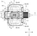
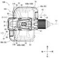
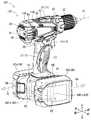
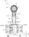
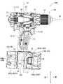
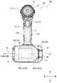
次に、本発明に係る第1の実施の形態を図1〜図9を参照しながら説明する。図1に示す符号10は、本発明に係る電動工具に相当するドライバドリルである。すなわち、図1は、第1の実施の形態のドライバドリル10の外観全体を示す斜視図である。図2は、図1に示すドライバドリル10を側面で視た側面図である。図3は、図1に示すドライバドリル10を上側から視た平面図である。図4は、図1に示すドライバドリル10を下側から視た平面図である。図5は、図1に示すドライバドリル10の半割り内部構造を示す内部構造図である。図6は、図5の(VI)-(VI)断面矢視を示す内部構造図である。図7は、バッテリ装着部60にスライドさせて装着される充電式バッテリ80の斜視図である。図8は、図4のバッテリ端子接続部600を拡大して示す平面図である。図9は、電動モータ25の回路構造を模式化して概念的に示す概念回路図である。なお、以下の説明では、図中に記載される方向を用いてドライバドリル10を説明する。より詳しく言えば、このようなドライバドリル10の前後上下左右はモータ軸26の配設位置を鑑みて設定される。このモータ軸26が延びる方向がドライバドリル10の前後方向として規定される。具体的には、モータ軸26に対してスピンドル50が配設される側が、ドライバドリル10における相対的な前側を指している。また、ハンドル部13に対してモータ軸26が配設される側が、ドライバドリル10における相対的な上側を指している。つまり、この反対側となる充電式バッテリ80の装着側が下側として規定される。このような前後上下に基づき、このドライバドリル10の左右方向が規定されている。なお、図示符号X1は、モータ軸26の軸線である。
このドライバドリル10は、ユーザが手で持って螺子締め作業等を行うための手持ち式の螺子締め工具である。このドライバドリル10は、本発明に係る電動工具に相当する。このドライバドリル10は、供給電力の電圧が36Vに設定されるハイパワータイプのドライバドリルである。このドライバドリル10は、充電式バッテリ80から供給される電力により駆動する電動工具である。このため、このドライバドリル10は、充電式バッテリ80がスライドさせて装着される工具本体100を備える。
すなわち、このドライバドリル10は、充電式バッテリ80からの供給電力により電動モータ25にて回転駆動力を発生させる。この回転駆動力は、後に説明する減速機構と動力伝達遮断機構とを介してスピンドル50に伝達される。このスピンドル50には、適宜のビット(不図示)が取り付けられるチャック52が設けられている。なお、この不図示のビットは、本発明に係る先端工具に相当する。また、このチャック52は、本発明に係る先端工具取付部に相当する。[First Embodiment]
Next, a first embodiment according to the present invention will be described with reference to FIGS. The code |
The
That is, the
工具本体100は、概略、ハウジング11と各種の内装部品とにより構成される。このハウジング11は、2つ割りにされた左ハウジング11Aと右ハウジング11Bとを合体させることにより構成される。また、このハウジング11は、機能的にグリップハウジング部12と、本体ハウジング部21とに区分けすることができる。グリップハウジング部12は、このドライバドリル10のハンドル部13を形成する。ハンドル部13は、ピストルのハンドルを模した形状にて形成されている。このため、グリップハウジング部12は、上下方向で適宜に延びるように形成される。
このグリップハウジング部12の上部には操作スイッチ14が設けられている。操作スイッチ14は、図5に示すように、スイッチ本体15と、操作ボタン部16とを備える。スイッチ本体15は、内装されるグリップハウジング部12にて支持される。このスイッチ本体15は、広く利用される接点スイッチにて構成されている。操作ボタン部16は、前後方向に移動可能にグリップハウジング部12に支持されている。この操作ボタン部16は、ハンドル部13の握り方向に沿った押込み操作がされることにより、スイッチ本体15の接点をオンとするように設けられている。接点がオンとされたスイッチ本体15は、スイッチオンとする旨の信号をコントローラ18に入力する。なお、操作ボタン部16が押込み操作されていない場合には、不図示の付勢ばねにより操作ボタン部16の押込みは解除され、スイッチ本体15の接点はオフとされる。なお、ハンドル部13のグリップ形状としては、ユーザにて手握りされた際に、中指、薬指および小指により握れるように更に人指し指で操作スイッチ14を引き操作できるように、形状設定がなされている。
また、このグリップハウジング部12の上端かつ前端の部分には、LED照明装置17が設けられている。このLED照明装置17は、操作スイッチ14のスイッチオン操作により、作業部分を照射する。The
An
Further, an
このグリップハウジング部12の上側には、このグリップハウジング部12と一体に連接される本体ハウジング部21が設けられている。この本体ハウジング部21は、前後方向に適宜に延びるように形成される。この本体ハウジング部21の内部には、ドライバドリル10としての駆動するための各種の内装部品が装置される。なお、この本体ハウジング部21の最後部には、本体ハウジング部21の最後部の開口状態を閉塞する後部カバー35が取り付けられている。
本体ハウジング部21の内部には、後部から前部に向けて、電動モータ25と、遊星歯車減速機構41と、クラッチ機構45とを備える。電動モータ25は、モータ軸26を回転駆動させる。このモータ軸26は、後側ベアリング31と前側ベアリング32とに、回転可能に支持されている。なお、後側ベアリング31は、後部カバー35により支持されている。また、前側ベアリング32は、ブラケット部材37を介して本体ハウジング部21に支持されている。つまり、このモータ軸26は、ハンドル部13の上側に設けられ且つ前後方向に延びるようになっている。
電動モータ25は、供給電力によりモータ軸26を回転駆動させる。この電動モータ25は、所謂ブラシモータで構成され、ステータ27と、ロータ28と、コンミテータ29とを備える。ステータ27は、本体ハウジング部21にて支持される永久磁石となっている。ロータ28は、コイルが巻回されることにより形成される。このロータ28の回転軸としてモータ軸26が設定されている。モータ軸26のうちロータ28の後側には、冷却ファン33が取り付けられている。この冷却ファン33の後側には、カーボンを支持するためのカーボン保持具30が設けられている。このカーボン保持具30は、本体ハウジング部21にて支持される。
モータ軸26に取り付けられた冷却ファン33は、モータ軸26の回転駆動を受けて送風する。この送風は、本体ハウジング部21に設けられる前側吸気孔38と、後部カバー35に設けられる後側吸気孔39と、後に説明する連接拡大部70に設けられる通風孔72と、から外気を吸気する。また、このように吸気された外気は、ハウジング11の内部を通って各種の部材を冷却した後に、本体ハウジング部21に設けられる排気孔40から外部に排気される。On the upper side of the
An
The
The cooling
電動モータ25の前側には、減速機構と動力伝達遮断機構とが設けられている。また、これら減速機構と動力伝達遮断機構との前側には、これら減速機構と動力伝達遮断機構とを介して伝達された回転駆動を出力するスピンドル50が設けられている。すなわち、電動モータ25の前側には、減速機構としての遊星歯車減速機構41と、動力伝達遮断機構としてのクラッチ機構45とが、設けられている。
遊星歯車減速機構41は、上記した電動モータ25によるモータ軸26の回転駆動を減速させる。このため、この遊星歯車減速機構41は、モータ軸26の回転駆動が入力されるように構成される。また、この遊星歯車減速機構41は、このモータ軸26の回転駆動を減速させた回転駆動を出力するように構成される。この遊星歯車減速機構41の構成は、各種の特許文献にて開示されるが、開示特許文献の1つとしては『特願2011−83935(特開2012−218088)』が挙げられる。この開示特許文献では、振動ドライバドリルにおける減速機構の構成として遊星歯車減速機構が設けられている。また、本体ハウジング部21の上部には、この遊星歯車減速機構41に関する変速レバー43が設けられている。この変速レバー43を前後方向でスライド操作すると、遊星歯車減速機構41による減速比率を適宜の比率に変更することができる。
クラッチ機構45は、上記した遊星歯車減速機構41から出力される回転トルクが所定以上の回転トルクとなった場合に、この遊星歯車減速機構41から出力される回転駆動のスピンドル50への動力伝達を遮断する。このクラッチ機構45の構成は、各種の特許文献にて開示されるが、開示特許文献の1つとしても上記と同様の『特願2011−83935(特開2012−218088)』が挙げられる。この開示特許文献では、振動ドライバドリルにおける動力伝達遮断機構の構成としてクラッチ機構が設けられている。また、本体ハウジング部21の前端には、このクラッチ機構45に関するトルク調節リング47が設けられている。このトルク調節リング47を回転操作すると、クラッチ機構45により動力伝達を遮断する回転トルクを適宜の回転トルクに変更することができる。
このクラッチ機構45の前側には、上記した電動モータ25のモータ軸26から伝達される回転駆動力を外部に出力するスピンドル50が設けられている。このスピンドル50には、上記したようにチャック52が取り付けられている。A reduction mechanism and a power transmission cutoff mechanism are provided on the front side of the
The planetary gear
The
A
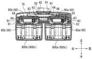
上記したグリップハウジング部12の下部には、バッテリ装着部60が設けられている。このバッテリ装着部60は、充電式バッテリ80がスライドさせて装着されるように構成される。つまり、グリップハウジング部12は、下側のバッテリ装着部60を支持するように、2つ充電式バッテリ80a,80bを接続可能とするための連接拡大部70が設けられている。この連接拡大部70には、図4に示すように、2つのバッテリ装着部60a,60bが設けられている。つまり、2つのバッテリ装着部60a,60bのそれぞれには、スライドさせることにより装着される充電式バッテリ80a,80bが取り付けられる。この充電式バッテリ80a,80bは、図7に示すように、広く汎用される供給電力の電圧が18Vに設定される充電式バッテリ80である。この充電式バッテリ80は、スライドさせることによってバッテリ装着部60に装着されるいわゆるスライド式装着型の充電式バッテリとなっている。このため、この充電式バッテリ80の図示上面(接続端子配置面)側には、スライド装着させるための構造および電気的接続がなされる構造が設けられている。
図7に示すように、充電式バッテリ80の図示上面側には、スライド装着させるための構造として、対をなすスライドガイド部81,82が設けられている。また、この充電式バッテリ80の図示上面側には、電気的接続がなされる構造として、正極側端子83と負極側端子84と信号側端子85とが設けられている。また、この充電式バッテリ80の図示上面側には、充電式バッテリ80をスライド装着させて電気的接続がなされた際に、この状態にて充電式バッテリ80をバッテリ装着部60に対して係合させた状態とする雄フック87が設けられている。また、この充電式バッテリ80の取り外し方向側には、上記した雄フック87を操作するための押しボタン88が設けられている。この押しボタン88は雄フック87と連結している。この押しボタン88を押し操作することで、雄フック87が動作して充電式バッテリ80の内部に収納される。これにより、充電式バッテリ80がバッテリ装着部60に対して係合しない状態となり、充電式バッテリ80をバッテリ装着部60から取り外せるようになる。なお、図7に記載される符号Lは、この充電式バッテリ80の長手方向の長さを示している。また、図7に記載される符号Wは、この充電式バッテリ80の幅方向の長さを示している。また、図7に記載される符号Hは、この充電式バッテリ80の高さ方向の長さを示している。つまり、この充電式バッテリ80の外形寸法は、長手方向の長さL>幅方向の長さW>高さ方向の長さH、という大小関係にある略直方体形状を有して形成されている。A
As shown in FIG. 7, a pair of
次に、上記した充電式バッテリ80をスライドさせて装着させるバッテリ装着部60について説明する。図4および図8に示すように、このバッテリ装着部60は、上記した充電式バッテリ80をスライドさせて装着される構造を有する。このため、上記した充電式バッテリ80に対応する装着構造を有して構成される。すなわち、バッテリ装着部60は、図4および図8に示すように、上記した充電式バッテリ80をスライド装着させるための構造、および上記した充電式バッテリ80を電気的接続をする構造が設けられている。図4に示すように、このバッテリ装着部60には、スライド装着させるための構造として、対をなすスライドガイド受部61,62が設けられている。また、図8に示すように、このバッテリ装着部60には、電気的接続がなされる構造として、正極側端子63と負極側端子64と信号側端子65とを備えるバッテリ端子接続部600が設けられている。また、図4および図7に示すように、このバッテリ装着部60には、充電式バッテリ80をスライド装着させて電気的接続がなされた際に、この状態の充電式バッテリ80がバッテリ装着部60にロックされる。つまり、バッテリ装着部60には、この状態の充電式バッテリ80の雄フック87が係合する雌部(凹み)66が設けられている。 Next, the
このように第1および第2のバッテリ装着部60a,60bに装着された充電式バッテリ80a,80bは、コントローラ18により制御される。すなわち、ドライバドリル10の電動モータ25の回転駆動は、図9に示す概念回路図のようにコントローラ18により制御されている。すなわち、コントローラ18は、操作スイッチ14およびシャント抵抗181(コントローラ18の一部)からの入力信号を受けて、FET(field-effect transistor)回路182(コントローラ18の一部)に出力信号を送る。これにより、コントローラ18は、電動モータ25の回転駆動を制御している。この際、第1および第2のバッテリ装着部60a,60bに装着される充電式バッテリ80a,80bは、直列方向の接続となるように回路設計されている。このため、充電式バッテリ80a,80bから供給される電力は、第1および第2のバッテリ装着部60a,60bを介して電圧が『36V』となる直列接続構造となるように設定されている。なお、このコントローラ18は、従前から利用されている電動モータ25の駆動を制御するコントローラのほか、2つのバッテリ装着部60a,60bに装着された2つの充電式バッテリ80a,80bから電力供給を制御するコントローラの、両方の機能が組み込まれている。このコントローラ18は、上記した連接拡大部70とグリップハウジング部12との両方に亘る範囲に設置されている。 Thus, the
次に、連接拡大部70に設けられる第1バッテリ装着部60aと第2バッテリ装着部60bとについて図4等を参照しながら説明する。なお、この連接拡大部70は、図示するように2つのバッテリ装着部60(60a,60b)を配設することができるように上下方向および平面方向に適宜に拡がって形成されている。この第1バッテリ装着部60aと第2バッテリ装着部60bとは、この連接拡大部70に対して左右方向でずらされた並列配置関係にて設けられている。このため、これら第1および第2のバッテリ装着部60a,60bに対する充電式バッテリ80a,80bのスライド装着方向は、両方とも前から後に向けてスライドさせることにより取り付けられるように設定されている。つまり、これら第1バッテリ装着部60aと第2バッテリ装着部60bとは、モータ軸26の軸線に対して対称となる位置にそれぞれ1つずつ配置されるように2つ設けられるようになっている。
図示符号X3にて示す仮想線は、第1バッテリ装着部60aに対して充電式バッテリ80aがスライド装着される軸線を示している。また、図示符号X4にて示す仮想線は、第2バッテリ装着部60bに対して充電式バッテリ80bがスライド装着される軸線を示している。なお、これら第1および第2のバッテリ装着部60a,60bは、上記したバッテリ装着部60の構造にて構成されている。これら軸線X3と軸線X4とは、互いに平行となるように設定されている。つまり、第1の実施の形態のバッテリ装着部60a,60bは、2つの充電式バッテリ80a,80bが並列にスライドさせて装着できるように、グリップハウジング部12の下部に設けられる連接拡大部70に対して設けられている。Next, the 1st
An imaginary line indicated by a reference symbol X3 indicates an axis on which the
つまり、これら第1および第2のバッテリ装着部60a,60bに対しての充電式バッテリ80a,80bのスライド装着させる方向は、図示符号X3および図示符号X4に示すように、互いに平行となる方向に設定されている。なお、これら第1および第2のバッテリ装着部60a,60bは、グリップハウジング部12に対してモータ軸16の軸線X1に対して、互いに左右対称位置にそれぞれ1つずつ配置されるように設けられている。
また、これら2つの第1および第2のバッテリ装着部60a,60bに装着される2つの充電式バッテリ80a,80bの合成重心の位置X5は、2つの充電式バッテリ80a,80bが取り外された工具本体100の重心の鉛直軸線X2の延長上に位置するようになっている。言い換えれば、2つの充電式バッテリ80a,80bが装着される前と、2つの充電式バッテリ80a,80bが装着された後とでは、工具本体100の重心の鉛直軸線X2の位置は、なるべく変わりないように設定されている。なお、この工具本体100の重心の鉛直軸線X2は、ハンドル部13を手握りした際のドライバドリル10の前後重量のバランスにおいて良好とされる重力方向に一致する。
なお、上記した連接拡大部70の側面には、この連接拡大部70の内部と外部とを貫通させる通風孔72が設けられている。この通風孔72は、上記した冷却ファン33による送風によって外気を吸気する孔となっている。この通風孔72から連接拡大部70の内部に吸気された外気は、上記したコントローラ18を冷却しつつ、連接拡大部70の内部、グリップハウジング部12の内部、本体ハウジング部21の内部へと、順次送られていく。そして、このように送られた風は、排気孔40から外部に排気される。That is, the direction in which the
The position X5 of the combined center of gravity of the two
Note that a
この第1の実施の形態のドライバドリル10によれば、次の作用効果を奏することができる。すなわち、上記した実施の形態のドライバドリル10によれば、2つの充電式バッテリ80a,80bを装着可能とするバッテリ装着部60a,60bが2つ設けられているので、ドライバドリル10として利用するにあたって電圧を高く設定したり供給容量を大きく設定したりする要請に応じることができる。また、このドライバドリル10によれば、2つのバッテリ装着部60a,60bは、スライド装着タイプのバッテリ装着部として構成されるので、2つのバッテリ装着部60a,60bは、スライドさせることにより装着されるスライド装着タイプの充電式バッテリ80a,80bに対応させることができる。したがって、ドライバドリル10として利用するにあたって電圧を高く設定したり供給容量を大きく設定したりする要請に応じることができつつ、汎用性に優れた充電式バッテリ80を利用することができる。さらに、上記した実施の形態のドライバドリル10によれば、第1および第2のバッテリ装着部60a,60bは、モータ軸26の軸線X1に対して対称となる位置にそれぞれ1つずつ配置されるように2つ設けられている。これによって、これら2つの第1および第2のバッテリ装着部60a,60bに充電式バッテリ80a,80bを装着させた場合でも、このドライバドリル10の左右の重量バランスをバランスさせることができる。したがって、手で持って螺子締め作業等を行うにあたって、左右のバランスに優れたドライバドリル10としての取回しの良さも維持することができる。 According to the
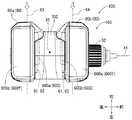
また、上記した実施の形態のドライバドリル10によれば、2つの第1および第2のバッテリ装着部60a,60bに装着された充電式バッテリ80a,80bの合成重心X5は、これら2つの充電式バッテリ80a,80bが取り外された工具本体100の重心の鉛直軸線X2上に位置される。これによって、充電式バッテリ80a,80bが取り付けられた状態でも、ドライバドリル10の本来の取回しの良さに差が生じない工具とすることができる。また、上記した実施の形態のドライバドリル10によれば、これら2つのバッテリ装着部60a,60bのそれぞれにスライド装着された2つの充電式バッテリ80a,80bの下面800a,800bのそれぞれが互いに同一平面をなすように、これら2つのバッテリ装着部60a,60bのそれぞれの位置が設定されている。これによって、スライド装着された2つの充電式バッテリ80a,80bの下面800a,800bのそれぞれは、互いに面一をなす共通下面800cをなすこととなる。したがって、ドライバドリル10を置いておきたい場合には、面一をなす共通下面800cを載置面に対面させて置けば、このドライバドリル10を安定して置いておくことができる。 Further, according to the
[第2の実施の形態]
次に、上記した第1の実施の形態の変形例となる第2の実施の形態について図10〜図13を参照しながら説明する。なお、この第2の実施の形態を含み、以下に説明する他の実施の形態にあっては、上記した第1の実施の形態のドライバドリル10のうちバッテリ装着部60の配設構成のみが相違するものとなっている。このため、上記した第1の実施の形態と略同様に構成される箇所については、上記した第1の実施の形態の説明において付した符号と同一の符号を図面に付して、その説明については省略するものとする。
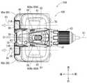
この第2の実施の形態のドライバドリル10Aは、上記した第1の実施の形態のドライバドリル10と比較して、充電式バッテリ80a,80bのスライドして装着させる方向が、いずれとも逆になった例である。このため、この第2の実施の形態の第1バッテリ装着部60Aa(60A)と第2バッテリ装着部60Ab(60A)とは、両方とも第1の実施の形態の第1バッテリ装着部60a(60)と第2バッテリ装着部60b(60)とは逆向きとなって配設されている。この第2の実施の形態のドライバドリル10Aのように構成した場合であっても、上記した第1の実施の形態のドライバドリル10と略同様の作用効果を奏することができる。ただ、この第2の実施の形態のドライバドリル10Aでは、右手でハンドル部13を握りながら充電式バッテリ80が取り付けられているか否かの目視確認できるので、上記した第1の実施の形態のドライバドリル10のよりも行い易い。逆に言えば、左手でハンドル部13を握りながら右手で充電式バッテリ80を取り付けたり取り外したりするにあたっては、この両手を向かい合わせるようにして充電式バッテリ80の取付け取外しを行うことができる観点から、上記した第1の実施の形態のドライバドリル10のほうが行い易い。[Second Embodiment]
Next, a second embodiment that is a modification of the first embodiment described above will be described with reference to FIGS. In addition, in other embodiments described below including the second embodiment, only the arrangement configuration of the
In the
[第3の実施の形態]
次に、上記した第1の実施の形態の変形例となる第3の実施の形態について図14〜図17を参照しながら説明する。
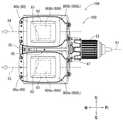
この第2の実施の形態のドライバドリル10Bは、上記した第1および第2の実施の形態のドライバドリル10,10Aと比較して、充電式バッテリ80a,80bのスライドして装着させる方向が、片側だけ逆になった例である。このため、この第3の実施の形態の第1バッテリ装着部60Ba(60B)については、第1の実施の形態の第1バッテリ装着部60a(60)と同様に構成され、この第3の実施の形態の第2バッテリ装着部60Bb(60B)については、第2の実施の形態の第2バッテリ装着部60b(60)と同様に構成される。この第3の実施の形態のドライバドリル10Bのように構成した場合であっても、上記した第1の実施の形態のドライバドリル10と略同様の作用効果を奏することができる。ただ、この第3の実施の形態のドライバドリル10Bでは、並列される充電式バッテリ80a,80bの装着方向が対向方向となるので、充電式バッテリ80の側面が握り易くなるので、充電式バッテリ80を取り付けたり取り外したりするのが行い易くなる。[Third Embodiment]
Next, a third embodiment, which is a modification of the above-described first embodiment, will be described with reference to FIGS.
Compared with the driver drills 10 and 10A of the first and second embodiments described above, the
[第4の実施の形態]
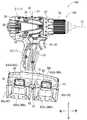
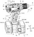
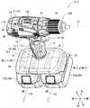
次に、上記した第1の実施の形態の変形例となる第4の実施の形態について図18〜図21を参照しながら説明する。この第4の実施の形態のドライバドリル10Cは、上記した第1の実施の形態のドライバドリル10と比較して、第1バッテリ装着部60Ca(60C)と第2バッテリ装着部60Cb(60C)とが設けられる連接拡大部70C全体を、グリップハウジング部12に対して右側に90度回転させるようにした例である。このため、この第4の実施の形態の第1バッテリ装着部60Ca(60C)と第2バッテリ装着部60Cb(60C)については、連接拡大部70Cに対して前後方向でずらされた並列配置関係にて設けられている。このため、これら第1および第2のバッテリ装着部60Ca,60Cbに対する充電式バッテリ80a,80bのスライド装着方向は、両方とも右から左に向けてスライドさせることにより取り付けられるように設定されている。これら第1バッテリ装着部60Caと第2バッテリ装着部60Cbとは、モータ軸26が延びる前後方向で並べられて2つ設けられている。このため、これら第1バッテリ装着部60Caと第2バッテリ装着部60Cbとは、充電式バッテリ80a,80bのスライド装着させる方向がモータ軸26の軸線X1に対して交差する方向となるように2つ設けられるようになっている。
このドライバドリル10Cによれば、ここで第1および第2のバッテリ装着部60Ca,60Cbは、モータ軸26が延びる前後方向で並べられて2つ設けられているので、これら第1および第2のバッテリ装着部60Ca,60Cbに装着される充電式バッテリ80a,80bの嵩張りを前後方向で拡げることとなる。ここで、ドライバドリル10Cのモータ軸26は前後方向に延びるように設定されているので、これら充電式バッテリ80a,80bの嵩張りをモータ軸26が延びる方向に合わせることができる。したがって、充電式バッテリ80a,80bの嵩張りは、ドライバドリル10Cとして必要とされるモータ軸26の延びる方向に従わせるので、充電式バッテリ80a,80bを装着されたドライバドリル10C全体の大きさも抑えることができる。これによって、手で持って螺子締め作業等を行うにあたっての、ドライバドリル10Cとしての取回しの良さを維持することができる。[Fourth Embodiment]
Next, a fourth embodiment, which is a modification of the above-described first embodiment, will be described with reference to FIGS. Compared with the
According to the driver drill 10C, since the first and second battery mounting portions 60Ca and 60Cb are provided in two in the front-rear direction in which the
さらに、図19に示すように、これら第1および第2のバッテリ装着部60Ca,60Cbに装着された2つの充電式バッテリ80a,80bの合成重心の位置X5は、2つの充電式バッテリ80a,80bが取り外された工具本体100の重心の鉛直軸線X2上に配置される。これによって、充電式バッテリ80a,80bが取り付けられた状態でも、ドライバドリル10Cの本来の取回しの良さに差が生じない工具とすることができる。また、上記した実施の形態のドライバドリル10Cによれば、これら2つのバッテリ装着部60a,60bのそれぞれにスライド装着された2つの充電式バッテリ80a,80bの下面800a,800bのそれぞれが互いに同一平面をなすように、これら2つのバッテリ装着部60a,60bのそれぞれの位置が設定されている。これによって、スライド装着された2つの充電式バッテリ80a,80bの下面800a,800bのそれぞれは、互いに面一をなす共通下面800cをなすこととなる。したがって、ドライバドリル10Cを置いておきたい場合には、面一をなす共通下面800cを載置面に対面させて置けば、このドライバドリル10Cを安定して置いておくことができる。また、このドライバドリル10Cによれば、左手でハンドル部13を握りながら右手で充電式バッテリ80を取り付けたり取り外したりするにあたっては、この両手を向かい合わせるようにして充電式バッテリ80の取付け取外しを行うことができる観点から行い易いものとなっている。 Further, as shown in FIG. 19, the position X5 of the combined center of gravity of the two
[第5の実施の形態]
次に、上記した第4の実施の形態の変形例となる第5の実施の形態について図22〜図25を参照しながら説明する。この第5の実施の形態のドライバドリル10Dは、上記した第4の実施の形態のドライバドリル10Cと比較して、充電式バッテリ80a,80bのスライドして装着させる方向が、片側だけ逆になった例である。このため、この第5の実施の形態の第2バッテリ装着部60Db(60D)については、第4の実施の形態の第2バッテリ装着部60Cb(60C)と同様に構成され、この第5の実施の形態の第1バッテリ装着部60Da(60D)については、第4の実施の形態の第1バッテリ装着部60Ca(60C)とは逆になるように構成される。この第5の実施の形態のドライバドリル10Dのように構成した場合であっても、上記した第4の実施の形態のドライバドリル10Cと略同様の作用効果を奏することができる。ただ、この第5の実施の形態のドライバドリル10Dでは、並列される充電式バッテリ80a,80bの装着方向が対向方向となるので、このドライバドリル10Dの左右の重量バランスをバランスさせることができる。したがって、手で持って螺子締め作業等を行うにあたって、左右のバランスに優れたドライバドリル10Dとしての取回しの良さも維持することができる。[Fifth Embodiment]
Next, a fifth embodiment, which is a modification of the above-described fourth embodiment, will be described with reference to FIGS. In the
[第6の実施の形態]
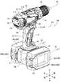
次に、上記した第1および第4の実施の形態とは相違する第6の実施の形態について図26〜図29を参照しながら説明する。この第6の実施の形態のドライバドリル10Eは、上記した第1の実施の形態のドライバドリル10と比較して、充電式バッテリ80a,80bを横向きにして前から後にスライド装着させるように構成される例である。具体的には、この第6の実施の形態の第1バッテリ装着部60Ea(60E)と第2バッテリ装着部60Eb(60E)については、連接拡大部70Eに対して左右方向でずらされた並列配置関係にて設けられている。つまり、これら第1バッテリ装着部60Eaと第2バッテリ装着部60Ebとは、モータ軸26の軸線X1に対して、互いに左右対称位置にそれぞれ1つずつ配置されるように設けられている。言い換えれば、これら第1バッテリ装着部60Eaと第2バッテリ装着部60Ebとは、充電式バッテリ80a,80bの接続端子配置面同士で、グリップハウジング部12の連接拡大部70Eを挟み込むように設けられている。これら第1および第2のバッテリ装着部60Ea,60Ebは、互いに反対側となる両側面に面して設けられる。このため、これら第1および第2のバッテリ装着部60Ea,60Ebにスライド装着された充電式バッテリ80a,80bは横置きにされている。なお、これら第1および第2のバッテリ装着部60Ea,60Ebに対しての充電式バッテリ80a,80bのスライド装着方向は、両方とも前から後に向けてスライドさせることにより取り付けられるように設定されている。[Sixth Embodiment]
Next, a sixth embodiment different from the first and fourth embodiments described above will be described with reference to FIGS. The
このドライバドリル10Eによれば、上記した第1の実施の形態のドライバドリル10と略同様の作用効果を奏することができる。なお、このドライバドリル10Eによれば、これら2つのバッテリ装着部60a,60bのそれぞれにスライド装着された2つの充電式バッテリ80a,80bの側面800d,800eのそれぞれが互いに同一平面をなすように、これら2つのバッテリ装着部60a,60bのそれぞれの位置が設定されている。これによって、スライド装着された2つの充電式バッテリ80a,80bの下面800d,800eのそれぞれは、互いに面一をなす共通下面800fをなすこととなる。したがって、ドライバドリル10Eを置いておきたい場合には、面一をなす共通下面800fを載置面に対面させて置けば、このドライバドリル10Eを安定して置いておくことができる。また、このドライバドリル10Eによれば、左手でハンドル部13を握りながら右手で充電式バッテリ80を取り付けたり取り外したりするにあたっては、この両手を向かい合わせるようにして充電式バッテリ80の取付け取外しを行うことができる観点から行い易いものとなっている。 According to this
[第7の実施の形態]
次に、上記した第6の実施の形態の変形例となる第7の実施の形態について図30〜図33を参照しながら説明する。この第7の実施の形態のドライバドリル10Fは、上記した第6の実施の形態のドライバドリル10Eと比較して、充電式バッテリ80a,80bのスライドして装着させる方向が、片側だけ逆になった例である。このため、この第7の実施の形態の第1バッテリ装着部60Fa(60F)については、第6の実施の形態の第1バッテリ装着部60Ea(60E)とは逆になるように構成され、この第7の実施の形態の第2バッテリ装着部60Fb(60F)については、第6の実施の形態の第2バッテリ装着部60Eb(60E)と同様に構成される。この第7の実施の形態のドライバドリル10Fように構成した場合であっても、上記した第6の実施の形態のドライバドリル10Eと略同様の作用効果を奏することができる。ただ、この第7の実施の形態のドライバドリル10Fでは、並列される充電式バッテリ80a,80bの装着方向が対向方向となるので、互いに面一をなす共通下面800fは、下面800d,800eを前後にずらされる範囲におよぶ。これによって、ドライバドリル10Fを、より一層安定して置いておくことができる。[Seventh Embodiment]
Next, a seventh embodiment, which is a modification of the above-described sixth embodiment, will be described with reference to FIGS. In the
[第8の実施の形態]
次に、上記した第6の実施の形態の変形例となる第8の実施の形態について図34〜図39を参照しながら説明する。
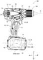
この第8の実施の形態のドライバドリル10Gは、上記した第6の実施の形態のドライバドリル10Eと比較して、第1バッテリ装着部60Ga(60G)と第2バッテリ装着部60Gb(60G)とが設けられる連接拡大部70G全体を、グリップハウジング部12に対して右側に90度回転させるようにした例である。このため、この第8の実施の形態の第1バッテリ装着部60Ga(60G)と第2バッテリ装着部60Gb(60G)については、連接拡大部70Gに対して前後方向でずらされた並列配置関係にて設けられている。このため、これら第1および第2のバッテリ装着部60Ga,60Gbに対する充電式バッテリ80a,80bのスライド装着方向は、両方とも右から左に向けてスライドさせることにより取り付けられるように設定されている。
これら第1バッテリ装着部60Gaと第2バッテリ装着部60Gbとは、モータ軸26が延びる前後方向で並べられて2つ設けられている。このため、これら第1バッテリ装着部60Gaと第2バッテリ装着部60Gbとは、充電式バッテリ80a,80bのスライド装着させる方向がモータ軸26の軸線X1に対して交差する方向となるように2つ設けられるようになっている。
このドライバドリル10Gによれば、ここで第1および第2のバッテリ装着部60Ga,60Gbは、モータ軸26が延びる前後方向で並べられて2つ設けられているので、これら第1および第2のバッテリ装着部60Ga,60Gbに装着される充電式バッテリ80a,80bの嵩張りを前後方向で拡げることとなる。ここで、ドライバドリル10Gのモータ軸26は前後方向に延びるように設定されているので、これら充電式バッテリ80a,80bの嵩張りをモータ軸26が延びる方向に合わせることができる。したがって、充電式バッテリ80a,80bの嵩張りは、ドライバドリル10Gとして必要とされるモータ軸26の延びる方向に従わせるので、充電式バッテリ80a,80bを装着されたドライバドリル10G全体の大きさも抑えることができる。これによって、手で持って螺子締め作業等を行うにあたっての、ドライバドリル10Gとしての取回しの良さを維持することができる。つまり、このドライバドリル10Gでは、上記した第4の実施の形態のドライバドリル10Cと、上記した第6の実施の形態のドライバドリル10Eとを組み合わせたような作用効果を奏することができる。[Eighth Embodiment]
Next, an eighth embodiment, which is a modification of the above-described sixth embodiment, will be described with reference to FIGS.
The
The first battery mounting portion 60Ga and the second battery mounting portion 60Gb are provided in a line in the front-rear direction in which the
According to the
[第9の実施の形態]
次に、上記した第8の実施の形態の変形例となる第9の実施の形態について図40〜図45を参照しながら説明する。この第9の実施の形態のドライバドリル10Hは、上記した第8の実施の形態のドライバドリル10Gと比較して、充電式バッテリ80a,80bのスライドして装着させる方向が、片側だけ逆になった例である。このため、この第9の実施の形態の第1バッテリ装着部60Ha(60H)については、第8の実施の形態の第1バッテリ装着部60Ga(60G)とは逆になるように構成され、この第9の実施の形態の第2バッテリ装着部60Hb(60H)については、第8の実施の形態の第2バッテリ装着部60Gb(60G)と同様に構成される。この第9の実施の形態のドライバドリル10Hのように構成した場合であっても、上記した第8の実施の形態のドライバドリル10Gと略同様の作用効果を奏することができる。ただ、この第9の実施の形態のドライバドリル10Hでは、並列される充電式バッテリ80a,80bの装着方向が対向方向となるので、このドライバドリル10Hの左右の重量バランスをバランスさせることができる。したがって、手で持って螺子締め作業等を行うにあたって、左右のバランスに優れたドライバドリル10Hとしての取回しの良さも維持することができる。さらに、互いに面一をなす共通下面800fは、下面800d,800eを左右にずらされる範囲におよぶ。これによって、ドライバドリル10Hを、より一層安定して置いておくことができる。[Ninth Embodiment]
Next, a ninth embodiment, which is a modification of the above-described eighth embodiment, will be described with reference to FIGS. In the
[第10の実施の形態]
次に、上記した第1の実施の形態の変形例となる第10の実施の形態について図46〜図53を参照しながら説明する。なお、図46は、第10の実施の形態のドライバドリル10Iの外観全体を示す斜視図である。図47は、図46に示すドライバドリル10Iを側面で視た側面図である。図48は、図46に示すドライバドリル10Iの半割り内部構造を示す内部構造図である。図49は、図48の(XXXXIX)部分を拡大して示す内部構造図である。図50は、図48の(XXXXX)-(XXXXX)断面矢視を示す内部構造図である。図51は、回転機構90の上面拡大図である。図52は、回転機構90の回転構造91を示す断面図である。図53は、バッテリ装着部60Iを90度回転させた図46に示すドライバドリル10Iの外観全体を示す斜視図である。
ところで、この第10の実施の形態のドライバドリル10Iにあっては、上記した第1の実施の形態のドライバドリル10の連接拡大部70の上側のグリップハウジング部12Iの下部に回転機構90が設けられている。この点において、この第10の実施の形態のドライバドリル10Iは、上記した第1の実施の形態のドライバドリル10と相違するものとなっている。このため、この第10の実施の形態のドライバドリル10Iにおいて、上記した第1の実施の形態と略同様に構成される箇所については、上記した第1の実施の形態の説明において付した符号と同一の符号を図面に付して、その説明については省略するものとする。[Tenth embodiment]
Next, a tenth embodiment, which is a modification of the above-described first embodiment, will be described with reference to FIGS. 46 to 53. FIG. 46 is a perspective view showing the entire appearance of the driver drill 10I according to the tenth embodiment. 47 is a side view of the driver drill 10I shown in FIG. 46 as viewed from the side. FIG. 48 is an internal structure diagram showing a halved internal structure of driver drill 10I shown in FIG. FIG. 49 is an internal structure diagram showing, on an enlarged scale, the (XXXXIX) portion of FIG. FIG. 50 is an internal structure diagram showing the (XXXXX)-(XXXXX) cross-sectional arrow of FIG. FIG. 51 is an enlarged top view of the
By the way, in the driver drill 10I according to the tenth embodiment, a
具体的には、図47に示すように、グリップハウジング部12Iの下部には、回転機構90が設けられている。この回転機構90は、グリップハウジング部12Iに対して連接拡大部70Iが相対的に回転できるようにする機構である。このバッテリ装着部60I(60Ia,60Ib)が設けられる連接拡大部70Iは、ハンドル部13のグリップ形状の延在方向に沿った回転軸を有してハンドル部13に対しての相対的な向きが変わるようにグリップハウジング部12Iに支持されている。このため、連接拡大部70Iがグリップハウジング部12Iに対して相対的に回転する回転軸は、ハンドル部13が延在される方向に沿ったものとなっている。このため、回転機構90は、グリップハウジング部12Iに対して連接拡大部70Iを前後左右平面で相対回転させて変位させるようになっている。すなわち、回転機構90は、回転構造91と係合構造93とを有して構成される。回転構造91は、グリップハウジング部12Iに対して連接拡大部70Iを相対回転可能とする構造である。具体的には、図52に示すように、連接拡大部70Iには、上側に突き出される環状内フランジ部911が設けられている。また、グリップハウジング部12Iの下端には、周方向溝形部912が設けられている。この環状内フランジ部911は、内周側に突き出されるフランジ形状が設けられている。また、周方向溝形部912には、環状内フランジ部911が嵌合可能な、周方向に沿って嵌合可能な溝形状が設けられている。これによって、連接拡大部70Iは、グリップハウジング部12Iに対して相対的に回転させることができるようになっている。 Specifically, as shown in FIG. 47, a
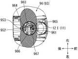
また、係合構造93は、図49に示す雄形機構95と、図50に示す雌形機構96とを備える。雄形機構95は、連接拡大部70Iに対して設けられている。この雄形機構95は、図49に示すように、連接拡大部70Iに固定される軸部951と、この軸部951に回動可能に軸支持される係合部材952と、この係合部材952を回動付勢する板ばね部957とを備える。係合部材952は、軸部951を支点に上下方向に回動できるようになっている。係合部材952は、支点と軸部951とは反対側に係合先端部953が設けられている。この係合先端部953は、次に説明する雌形機構96に設けられる係合孔961〜965に嵌合可能にされる部分である。この係合部材952の軸部951と係合先端部953との間には、操作部954が設けられている。この操作部954は、この係合部材952を下側に押込み操作できるように外部露出される部分に設定されている。このように軸部951により回動可能に支持される係合部材952は、板ばね部957より上側に付勢されている。この板ばね部957は、係合部材952の下側から当てる当接部958が設けられている。このようにして、この当接部958を係合部材952の下側から当てることにより、係合部材952の操作部954を外部に操作可能に露出させ、さらに係合先端部953を雌形機構96に設けられる係合孔963〜967に嵌合させておくことができる。逆に、係合部材952の操作部954を下側に押込み操作すると、雌形機構96に設けられる係合孔963〜967に対しての係合先端部953の嵌合は外れることとなる。 Further, the
これに対して、雌形機構96は、グリップハウジング部12Iに対して設けられている。この雌形機構96は、図50に示すように、環状をなす環状板部961に対して、周方向後側に均等間隔で5つの係合孔963〜967が設けられている。この係合孔963〜967は、上記した係合部材952に設けられる係合先端部953を嵌合可能とする矩形の孔にて形成されている。なお、この係合孔963〜967のいずれに対しても、係合部材952に設けられる係合先端部953を嵌合させることができる。つまり、グリップハウジング部12Iに対して連接拡大部70Iを相対回転させて、この相対回転させた位置で係合孔963〜967の一つに係合部材952の係合先端部953を嵌合させる。そうすると、このグリップハウジング部12Iに対しての連接拡大部70Iの相対位置で、両者を固定することができる。なお、係合孔965に係合先端部953を嵌合させている状態が、図46に示す連接拡大部70Iの相対位置となる。これに対し、係合孔967に係合先端部953を嵌合させている状態が、図53に示す連接拡大部70Iの相対位置となる。このようにして、グリップハウジング部12Iに対しての連接拡大部70Iの相対位置は、180度回転させることができる。
この第10の実施の形態のドライバドリル10Iによれば、上記した第1の実施の形態のドライバドリル10と略同様の作用効果を奏することができる上、さらに次のような作用効果を奏することができる。すなわち、この第10の実施の形態のドライバドリル10Iによれば、バッテリ装着部60I(60Ia,60Ib)のハンドル部13に対する相対的な向きが変えることができるので、工具の用途や収納に応じてバッテリ装着部60I(60Ia,60Ib)の位置を適宜に変更することができる。On the other hand, the
According to the driver drill 10I of the tenth embodiment, substantially the same operational effects as the above-described
なお、本発明に係る電動工具としては、上記したドライバドリルの例に限定されるものではなく、電動ドライバ、電動ドリル、ドライバドリル、振動ドライバドリル、インパクトドライバドリル等、手で持って螺子締め作業や孔開け作業を行うための手持ち式の電動工具であれば、上記した実施の形態の構成についてを適宜応用するようにして組み込まれるものであってよい。つまり、手持ち式の電動工具としては、例えばディスクサンダ、ポリッシャ等の研削、研磨、磨き、つや出し等の各種作業を行う各種の手持ち式の電動工具を、上記した実施の形態の例として応用することができる。
また、上記した実施の形態における充電式バッテリ80a,80bは、電圧18Vに設定されるものとなっていた。しかしながら、本発明に係る充電式バッテリの電圧としては、これに限定されることなく、10Vや14V等の適宜の電圧にて設計される充電式バッテリ(二次電池)を利用することができる。また、これら2つの充電式バッテリ80a,80bから供給される電力は、電圧を上げることのみならず、供給容量(全ての充電量)を高めるものであってもよい。つまり、充電式バッテリ80から供給される電力の電圧を上げるための構成に限定されることなく、充電式バッテリ80から供給される電力の供給容量を上げるための適宜の構成としてもよい。また、充電式バッテリの電圧としては、この例に限定されることなく、10Vや14V等の適宜の電圧にて設定されるものであってもよい。The power tool according to the present invention is not limited to the example of the driver drill described above, and is screwed by holding it by hand, such as an electric driver, electric drill, driver drill, vibration driver drill, impact driver drill, and the like. If it is a hand-held power tool for performing a drilling operation, it may be incorporated by appropriately applying the configuration of the embodiment described above. In other words, as a hand-held power tool, for example, various hand-held power tools that perform various operations such as grinding, polishing, polishing, and polishing of a disk sander, polisher, etc. are applied as examples of the above-described embodiments. Can do.
Moreover, the
10,10A,10B,10C,10D,10E,10F,10G,10H,10I ドライバドリル(電動工具)
100 工具本体
11 ハウジング
11A 左ハウジング
11B 右ハウジング
12 グリップハウジング部
13 ハンドル部
14 操作スイッチ
15 スイッチ本体
16 操作ボタン部
17 照明装置
18 コントローラ
21 本体ハウジング部
25 電動モータ
26 モータ軸
27 ステータ
28 ロータ
29 コンミテータ
30 カーボン保持具
31 後側ベアリング
32 前側ベアリング
33 冷却ファン
35 後部カバー
37 ブラケット部材
40 コントローラ
41 遊星歯車減速機構
43 変速レバー
45 クラッチ機構
47 トルク調節リング
50 スピンドル
52 チャック(先端工具取付部)
60(60a,60b) バッテリ装着部
600 バッテリ端子接続部
61,62 スライドガイド受部
63 正極側端子
64 負極側端子
65 信号側端子
80(80a,80b) 充電式バッテリ
800a,800b 充電式バッテリの下面
800c 共通下面
800d,800e 充電式バッテリの側面
800f 共通下面
81,82 スライドガイド部
83 正極側端子
84 負極側端子
85 信号側端子
87 雄フック
88 押しボタン
90 回転機構
91 回転構造
911 環状内フランジ部
912 周方向溝形部
93 係合構造
95 雄形機構
951 軸部
952 係合部材
953 係合先端部
954 操作部
957 板ばね部
958 当接部
96 雌形機構
961 環状板部
963〜967 係合孔
L 長手方向の長さ
W 幅方向の長さ
H 高さ方向の長さ
X1 モータ軸の延在方向を中心にした軸線
X2 充電式バッテリが取り外された工具本体の重心の鉛直軸線
X3 第1バッテリ装着部の装着方向軸線
X4 第2バッテリ装着部の装着方向軸線
X5 2つの充電式バッテリの合成重心の位置10, 10A, 10B, 10C, 10D, 10E, 10F, 10G, 10H, 10I Driver drill (power tool)
DESCRIPTION OF
60 (60a, 60b)
Claims (6)
Translated fromJapanese前記バッテリ装着部は、前記モータ軸が延びる前後方向に並べられて2つ設けられている、ことを特徴とする電動工具。A battery mounting portion on which the rechargeable battery is slid and mounted, a handle portion formed while supporting the battery mounting portion on the upper side of the battery mounting portion, and provided in the upper side of the handle portion and extending in the front-rear direction An electric tool having an electric motor for rotationally driving a motor shaft, and a tip tool mounting portion that is rotated by receiving rotational driving of the motor shaft on the front side of the motor shaft,
The battery mounting unit is provided with two battery tools arranged in the front-rear direction in which the motor shaft extends.
前記充電式バッテリには、当該充電式バッテリを前記バッテリ装着部から取外し操作するための押しボタンが設置されている、ことを特徴とする電動工具。The power tool according to claim 1,
The rechargeable battery is provided with a push button for removing and operating the rechargeable battery from the battery mounting portion .
前記充電式バッテリは、前記モータ軸が延びる前後方向に並べられて設けられたバッテリ装着部に左右方向にスライドさせて取付けられる、ことを特徴とする電動工具。The power tool according to claim 1,
The rechargeable battery is attached to a battery mounting portion that is arranged in the front-rear direction in which the motor shaft extends and is slid in the left-right direction .
前記バッテリ装着部に取り付けられた2つの充電式バッテリの下面は面一で、共通下面である、ことを特徴とする電動工具。The power tool according to claim 1,
The electric tool characterized bythe bottom surfaces of the two rechargeable batteries attached to the battery mounting part being flush with each other and a common lower surface .
前記バッテリ装着部が、スライドガイド受部を4つ有し、
該4つのスライドガイド受部は、前後方向に並んで配設されている、ことを特徴とする電動工具。
The power tool according to claim 1,
The battery mounting portion has four slide guide receiving portions,
The power tool characterized in that the four slide guide receiving portions are arranged side by side in thefront-rear direction .
前記バッテリ装着部が、スライドガイド受部を4つ有し、
該4つのスライドガイド受部は、上下方向及び前後方向に2つずつ並んで配設されている、ことを特徴とする電動工具。The power tool according to claim 1,
Thebattery mounting portion has four slide guide receiving portions,
The four slide guide receiving portions are arranged two by two in the up-down direction and the front-rear direction.
Priority Applications (4)
| Application Number | Priority Date | Filing Date | Title |
|---|---|---|---|
| JP2013018882AJP6033698B2 (en) | 2013-02-01 | 2013-02-01 | Electric tool |
| PCT/JP2013/084603WO2014119188A1 (en) | 2013-02-01 | 2013-12-25 | Electric power tool |
| DE112013006567.3TDE112013006567T5 (en) | 2013-02-01 | 2013-12-25 | Electric power tool |
| US14/762,634US20150367497A1 (en) | 2013-02-01 | 2013-12-25 | Electrical power tool |
Applications Claiming Priority (1)
| Application Number | Priority Date | Filing Date | Title |
|---|---|---|---|
| JP2013018882AJP6033698B2 (en) | 2013-02-01 | 2013-02-01 | Electric tool |
Related Child Applications (1)
| Application Number | Title | Priority Date | Filing Date |
|---|---|---|---|
| JP2016206627ADivisionJP6258435B2 (en) | 2016-10-21 | 2016-10-21 | Electric tool |
Publications (2)
| Publication Number | Publication Date |
|---|---|
| JP2014148022A JP2014148022A (en) | 2014-08-21 |
| JP6033698B2true JP6033698B2 (en) | 2016-11-30 |
Family
ID=51261912
Family Applications (1)
| Application Number | Title | Priority Date | Filing Date |
|---|---|---|---|
| JP2013018882AActiveJP6033698B2 (en) | 2013-02-01 | 2013-02-01 | Electric tool |
Country Status (4)
| Country | Link |
|---|---|
| US (1) | US20150367497A1 (en) |
| JP (1) | JP6033698B2 (en) |
| DE (1) | DE112013006567T5 (en) |
| WO (1) | WO2014119188A1 (en) |
Cited By (1)
| Publication number | Priority date | Publication date | Assignee | Title |
|---|---|---|---|---|
| JP2017007091A (en)* | 2016-10-21 | 2017-01-12 | 株式会社マキタ | Electric tool |
Families Citing this family (348)
| Publication number | Priority date | Publication date | Assignee | Title |
|---|---|---|---|---|
| US9060770B2 (en) | 2003-05-20 | 2015-06-23 | Ethicon Endo-Surgery, Inc. | Robotically-driven surgical instrument with E-beam driver |
| US20070084897A1 (en) | 2003-05-20 | 2007-04-19 | Shelton Frederick E Iv | Articulating surgical stapling instrument incorporating a two-piece e-beam firing mechanism |
| US8215531B2 (en) | 2004-07-28 | 2012-07-10 | Ethicon Endo-Surgery, Inc. | Surgical stapling instrument having a medical substance dispenser |
| US9072535B2 (en) | 2011-05-27 | 2015-07-07 | Ethicon Endo-Surgery, Inc. | Surgical stapling instruments with rotatable staple deployment arrangements |
| US11998198B2 (en) | 2004-07-28 | 2024-06-04 | Cilag Gmbh International | Surgical stapling instrument incorporating a two-piece E-beam firing mechanism |
| US11890012B2 (en) | 2004-07-28 | 2024-02-06 | Cilag Gmbh International | Staple cartridge comprising cartridge body and attached support |
| US11246590B2 (en) | 2005-08-31 | 2022-02-15 | Cilag Gmbh International | Staple cartridge including staple drivers having different unfired heights |
| US7934630B2 (en) | 2005-08-31 | 2011-05-03 | Ethicon Endo-Surgery, Inc. | Staple cartridges for forming staples having differing formed staple heights |
| US9237891B2 (en) | 2005-08-31 | 2016-01-19 | Ethicon Endo-Surgery, Inc. | Robotically-controlled surgical stapling devices that produce formed staples having different lengths |
| US7669746B2 (en) | 2005-08-31 | 2010-03-02 | Ethicon Endo-Surgery, Inc. | Staple cartridges for forming staples having differing formed staple heights |
| US10159482B2 (en) | 2005-08-31 | 2018-12-25 | Ethicon Llc | Fastener cartridge assembly comprising a fixed anvil and different staple heights |
| US11484312B2 (en) | 2005-08-31 | 2022-11-01 | Cilag Gmbh International | Staple cartridge comprising a staple driver arrangement |
| US20070106317A1 (en) | 2005-11-09 | 2007-05-10 | Shelton Frederick E Iv | Hydraulically and electrically actuated articulation joints for surgical instruments |
| US8820603B2 (en) | 2006-01-31 | 2014-09-02 | Ethicon Endo-Surgery, Inc. | Accessing data stored in a memory of a surgical instrument |
| US11278279B2 (en) | 2006-01-31 | 2022-03-22 | Cilag Gmbh International | Surgical instrument assembly |
| US20110295295A1 (en) | 2006-01-31 | 2011-12-01 | Ethicon Endo-Surgery, Inc. | Robotically-controlled surgical instrument having recording capabilities |
| US11224427B2 (en) | 2006-01-31 | 2022-01-18 | Cilag Gmbh International | Surgical stapling system including a console and retraction assembly |
| US8708213B2 (en) | 2006-01-31 | 2014-04-29 | Ethicon Endo-Surgery, Inc. | Surgical instrument having a feedback system |
| US7845537B2 (en) | 2006-01-31 | 2010-12-07 | Ethicon Endo-Surgery, Inc. | Surgical instrument having recording capabilities |
| US8186555B2 (en) | 2006-01-31 | 2012-05-29 | Ethicon Endo-Surgery, Inc. | Motor-driven surgical cutting and fastening instrument with mechanical closure system |
| US11793518B2 (en) | 2006-01-31 | 2023-10-24 | Cilag Gmbh International | Powered surgical instruments with firing system lockout arrangements |
| US7753904B2 (en) | 2006-01-31 | 2010-07-13 | Ethicon Endo-Surgery, Inc. | Endoscopic surgical instrument with a handle that can articulate with respect to the shaft |
| US20120292367A1 (en) | 2006-01-31 | 2012-11-22 | Ethicon Endo-Surgery, Inc. | Robotically-controlled end effector |
| US8992422B2 (en) | 2006-03-23 | 2015-03-31 | Ethicon Endo-Surgery, Inc. | Robotically-controlled endoscopic accessory channel |
| US8322455B2 (en) | 2006-06-27 | 2012-12-04 | Ethicon Endo-Surgery, Inc. | Manually driven surgical cutting and fastening instrument |
| US10568652B2 (en) | 2006-09-29 | 2020-02-25 | Ethicon Llc | Surgical staples having attached drivers of different heights and stapling instruments for deploying the same |
| US11980366B2 (en) | 2006-10-03 | 2024-05-14 | Cilag Gmbh International | Surgical instrument |
| US11291441B2 (en) | 2007-01-10 | 2022-04-05 | Cilag Gmbh International | Surgical instrument with wireless communication between control unit and remote sensor |
| US8632535B2 (en) | 2007-01-10 | 2014-01-21 | Ethicon Endo-Surgery, Inc. | Interlock and surgical instrument including same |
| US8684253B2 (en) | 2007-01-10 | 2014-04-01 | Ethicon Endo-Surgery, Inc. | Surgical instrument with wireless communication between a control unit of a robotic system and remote sensor |
| US20080169333A1 (en) | 2007-01-11 | 2008-07-17 | Shelton Frederick E | Surgical stapler end effector with tapered distal end |
| US7673782B2 (en) | 2007-03-15 | 2010-03-09 | Ethicon Endo-Surgery, Inc. | Surgical stapling instrument having a releasable buttress material |
| US11564682B2 (en) | 2007-06-04 | 2023-01-31 | Cilag Gmbh International | Surgical stapler device |
| US8931682B2 (en) | 2007-06-04 | 2015-01-13 | Ethicon Endo-Surgery, Inc. | Robotically-controlled shaft based rotary drive systems for surgical instruments |
| US7753245B2 (en) | 2007-06-22 | 2010-07-13 | Ethicon Endo-Surgery, Inc. | Surgical stapling instruments |
| US11849941B2 (en) | 2007-06-29 | 2023-12-26 | Cilag Gmbh International | Staple cartridge having staple cavities extending at a transverse angle relative to a longitudinal cartridge axis |
| US11986183B2 (en) | 2008-02-14 | 2024-05-21 | Cilag Gmbh International | Surgical cutting and fastening instrument comprising a plurality of sensors to measure an electrical parameter |
| US8636736B2 (en) | 2008-02-14 | 2014-01-28 | Ethicon Endo-Surgery, Inc. | Motorized surgical cutting and fastening instrument |
| JP5410110B2 (en) | 2008-02-14 | 2014-02-05 | エシコン・エンド−サージェリィ・インコーポレイテッド | Surgical cutting / fixing instrument with RF electrode |
| US7819298B2 (en) | 2008-02-14 | 2010-10-26 | Ethicon Endo-Surgery, Inc. | Surgical stapling apparatus with control features operable with one hand |
| US9179912B2 (en) | 2008-02-14 | 2015-11-10 | Ethicon Endo-Surgery, Inc. | Robotically-controlled motorized surgical cutting and fastening instrument |
| US7866527B2 (en) | 2008-02-14 | 2011-01-11 | Ethicon Endo-Surgery, Inc. | Surgical stapling apparatus with interlockable firing system |
| US8573465B2 (en) | 2008-02-14 | 2013-11-05 | Ethicon Endo-Surgery, Inc. | Robotically-controlled surgical end effector system with rotary actuated closure systems |
| US9585657B2 (en) | 2008-02-15 | 2017-03-07 | Ethicon Endo-Surgery, Llc | Actuator for releasing a layer of material from a surgical end effector |
| EP2110921B1 (en) | 2008-04-14 | 2013-06-19 | Stanley Black & Decker, Inc. | Battery management system for a cordless tool |
| US8210411B2 (en) | 2008-09-23 | 2012-07-03 | Ethicon Endo-Surgery, Inc. | Motor-driven surgical cutting instrument |
| US11648005B2 (en) | 2008-09-23 | 2023-05-16 | Cilag Gmbh International | Robotically-controlled motorized surgical instrument with an end effector |
| US9386983B2 (en) | 2008-09-23 | 2016-07-12 | Ethicon Endo-Surgery, Llc | Robotically-controlled motorized surgical instrument |
| US9005230B2 (en) | 2008-09-23 | 2015-04-14 | Ethicon Endo-Surgery, Inc. | Motorized surgical instrument |
| US8608045B2 (en) | 2008-10-10 | 2013-12-17 | Ethicon Endo-Sugery, Inc. | Powered surgical cutting and stapling apparatus with manually retractable firing system |
| US8517239B2 (en) | 2009-02-05 | 2013-08-27 | Ethicon Endo-Surgery, Inc. | Surgical stapling instrument comprising a magnetic element driver |
| US8851354B2 (en) | 2009-12-24 | 2014-10-07 | Ethicon Endo-Surgery, Inc. | Surgical cutting instrument that analyzes tissue thickness |
| US8220688B2 (en) | 2009-12-24 | 2012-07-17 | Ethicon Endo-Surgery, Inc. | Motor-driven surgical cutting instrument with electric actuator directional control assembly |
| US8783543B2 (en) | 2010-07-30 | 2014-07-22 | Ethicon Endo-Surgery, Inc. | Tissue acquisition arrangements and methods for surgical stapling devices |
| US9016542B2 (en) | 2010-09-30 | 2015-04-28 | Ethicon Endo-Surgery, Inc. | Staple cartridge comprising compressible distortion resistant components |
| US12213666B2 (en) | 2010-09-30 | 2025-02-04 | Cilag Gmbh International | Tissue thickness compensator comprising layers |
| US10945731B2 (en) | 2010-09-30 | 2021-03-16 | Ethicon Llc | Tissue thickness compensator comprising controlled release and expansion |
| US9386988B2 (en) | 2010-09-30 | 2016-07-12 | Ethicon End-Surgery, LLC | Retainer assembly including a tissue thickness compensator |
| US11812965B2 (en) | 2010-09-30 | 2023-11-14 | Cilag Gmbh International | Layer of material for a surgical end effector |
| US9351730B2 (en) | 2011-04-29 | 2016-05-31 | Ethicon Endo-Surgery, Llc | Tissue thickness compensator comprising channels |
| US11925354B2 (en) | 2010-09-30 | 2024-03-12 | Cilag Gmbh International | Staple cartridge comprising staples positioned within a compressible portion thereof |
| US9788834B2 (en) | 2010-09-30 | 2017-10-17 | Ethicon Llc | Layer comprising deployable attachment members |
| US11298125B2 (en) | 2010-09-30 | 2022-04-12 | Cilag Gmbh International | Tissue stapler having a thickness compensator |
| US9629814B2 (en) | 2010-09-30 | 2017-04-25 | Ethicon Endo-Surgery, Llc | Tissue thickness compensator configured to redistribute compressive forces |
| US8695866B2 (en) | 2010-10-01 | 2014-04-15 | Ethicon Endo-Surgery, Inc. | Surgical instrument having a power control circuit |
| AU2012250197B2 (en) | 2011-04-29 | 2017-08-10 | Ethicon Endo-Surgery, Inc. | Staple cartridge comprising staples positioned within a compressible portion thereof |
| US11207064B2 (en) | 2011-05-27 | 2021-12-28 | Cilag Gmbh International | Automated end effector component reloading system for use with a robotic system |
| MX358135B (en) | 2012-03-28 | 2018-08-06 | Ethicon Endo Surgery Inc | Tissue thickness compensator comprising a plurality of layers. |
| BR112014024098B1 (en) | 2012-03-28 | 2021-05-25 | Ethicon Endo-Surgery, Inc. | staple cartridge |
| US9101358B2 (en) | 2012-06-15 | 2015-08-11 | Ethicon Endo-Surgery, Inc. | Articulatable surgical instrument comprising a firing drive |
| US20140001231A1 (en) | 2012-06-28 | 2014-01-02 | Ethicon Endo-Surgery, Inc. | Firing system lockout arrangements for surgical instruments |
| BR112014032776B1 (en) | 2012-06-28 | 2021-09-08 | Ethicon Endo-Surgery, Inc | SURGICAL INSTRUMENT SYSTEM AND SURGICAL KIT FOR USE WITH A SURGICAL INSTRUMENT SYSTEM |
| JP6290201B2 (en) | 2012-06-28 | 2018-03-07 | エシコン・エンド−サージェリィ・インコーポレイテッドEthicon Endo−Surgery,Inc. | Lockout for empty clip cartridge |
| US9282974B2 (en) | 2012-06-28 | 2016-03-15 | Ethicon Endo-Surgery, Llc | Empty clip cartridge lockout |
| US11278284B2 (en) | 2012-06-28 | 2022-03-22 | Cilag Gmbh International | Rotary drive arrangements for surgical instruments |
| US12383267B2 (en) | 2012-06-28 | 2025-08-12 | Cilag Gmbh International | Robotically powered surgical device with manually-actuatable reversing system |
| US9408606B2 (en) | 2012-06-28 | 2016-08-09 | Ethicon Endo-Surgery, Llc | Robotically powered surgical device with manually-actuatable reversing system |
| US9289256B2 (en) | 2012-06-28 | 2016-03-22 | Ethicon Endo-Surgery, Llc | Surgical end effectors having angled tissue-contacting surfaces |
| US20150328764A1 (en) | 2013-02-01 | 2015-11-19 | Makita Corporation | Power tool |
| BR112015021082B1 (en) | 2013-03-01 | 2022-05-10 | Ethicon Endo-Surgery, Inc | surgical instrument |
| RU2672520C2 (en) | 2013-03-01 | 2018-11-15 | Этикон Эндо-Серджери, Инк. | Hingedly turnable surgical instruments with conducting ways for signal transfer |
| US9629629B2 (en) | 2013-03-14 | 2017-04-25 | Ethicon Endo-Surgey, LLC | Control systems for surgical instruments |
| BR112015026109B1 (en) | 2013-04-16 | 2022-02-22 | Ethicon Endo-Surgery, Inc | surgical instrument |
| US9826976B2 (en) | 2013-04-16 | 2017-11-28 | Ethicon Llc | Motor driven surgical instruments with lockable dual drive shafts |
| US9775609B2 (en) | 2013-08-23 | 2017-10-03 | Ethicon Llc | Tamper proof circuit for surgical instrument battery pack |
| MX369362B (en) | 2013-08-23 | 2019-11-06 | Ethicon Endo Surgery Llc | Firing member retraction devices for powered surgical instruments. |
| WO2015061370A1 (en) | 2013-10-21 | 2015-04-30 | Milwaukee Electric Tool Corporation | Adapter for power tool devices |
| US20150272580A1 (en) | 2014-03-26 | 2015-10-01 | Ethicon Endo-Surgery, Inc. | Verification of number of battery exchanges/procedure count |
| US12232723B2 (en) | 2014-03-26 | 2025-02-25 | Cilag Gmbh International | Systems and methods for controlling a segmented circuit |
| US10013049B2 (en) | 2014-03-26 | 2018-07-03 | Ethicon Llc | Power management through sleep options of segmented circuit and wake up control |
| BR112016021943B1 (en) | 2014-03-26 | 2022-06-14 | Ethicon Endo-Surgery, Llc | SURGICAL INSTRUMENT FOR USE BY AN OPERATOR IN A SURGICAL PROCEDURE |
| JP6328473B2 (en)* | 2014-04-09 | 2018-05-23 | 株式会社マキタ | Electric tool |
| CN106456176B (en) | 2014-04-16 | 2019-06-28 | 伊西康内外科有限责任公司 | Fastener Cartridge Including Extensions With Different Configurations |
| CN106456159B (en) | 2014-04-16 | 2019-03-08 | 伊西康内外科有限责任公司 | Fastener Cartridge Assembly and Nail Retainer Cover Arrangement |
| US10327764B2 (en) | 2014-09-26 | 2019-06-25 | Ethicon Llc | Method for creating a flexible staple line |
| BR112016023825B1 (en) | 2014-04-16 | 2022-08-02 | Ethicon Endo-Surgery, Llc | STAPLE CARTRIDGE FOR USE WITH A SURGICAL STAPLER AND STAPLE CARTRIDGE FOR USE WITH A SURGICAL INSTRUMENT |
| US20150297225A1 (en) | 2014-04-16 | 2015-10-22 | Ethicon Endo-Surgery, Inc. | Fastener cartridges including extensions having different configurations |
| US9673738B2 (en) | 2014-05-16 | 2017-06-06 | Techtronic Power Tools Technology Limited | Multi-battery pack for power tools |
| CN108616154B (en) | 2014-05-18 | 2021-09-14 | 百得有限公司 | Electric tool system |
| US9893384B2 (en) | 2014-05-18 | 2018-02-13 | Black & Decker Inc. | Transport system for convertible battery pack |
| JP6345523B2 (en)* | 2014-07-23 | 2018-06-20 | 株式会社やまびこ | Battery powered work machine |
| US11311294B2 (en) | 2014-09-05 | 2022-04-26 | Cilag Gmbh International | Powered medical device including measurement of closure state of jaws |
| US10135242B2 (en) | 2014-09-05 | 2018-11-20 | Ethicon Llc | Smart cartridge wake up operation and data retention |
| BR112017004361B1 (en) | 2014-09-05 | 2023-04-11 | Ethicon Llc | ELECTRONIC SYSTEM FOR A SURGICAL INSTRUMENT |
| US10105142B2 (en) | 2014-09-18 | 2018-10-23 | Ethicon Llc | Surgical stapler with plurality of cutting elements |
| CN107427300B (en) | 2014-09-26 | 2020-12-04 | 伊西康有限责任公司 | Surgical suture buttresses and auxiliary materials |
| US11523821B2 (en) | 2014-09-26 | 2022-12-13 | Cilag Gmbh International | Method for creating a flexible staple line |
| US9924944B2 (en) | 2014-10-16 | 2018-03-27 | Ethicon Llc | Staple cartridge comprising an adjunct material |
| CN104617853A (en)* | 2014-10-28 | 2015-05-13 | 常州格力博有限公司 | Pruning machine speed regulation control method |
| US11141153B2 (en) | 2014-10-29 | 2021-10-12 | Cilag Gmbh International | Staple cartridges comprising driver arrangements |
| US10517594B2 (en) | 2014-10-29 | 2019-12-31 | Ethicon Llc | Cartridge assemblies for surgical staplers |
| JP6408870B2 (en)* | 2014-11-05 | 2018-10-17 | 株式会社マキタ | Electric tool |
| US9844376B2 (en) | 2014-11-06 | 2017-12-19 | Ethicon Llc | Staple cartridge comprising a releasable adjunct material |
| US10736636B2 (en) | 2014-12-10 | 2020-08-11 | Ethicon Llc | Articulatable surgical instrument system |
| US9943309B2 (en) | 2014-12-18 | 2018-04-17 | Ethicon Llc | Surgical instruments with articulatable end effectors and movable firing beam support arrangements |
| US9987000B2 (en) | 2014-12-18 | 2018-06-05 | Ethicon Llc | Surgical instrument assembly comprising a flexible articulation system |
| US9844374B2 (en) | 2014-12-18 | 2017-12-19 | Ethicon Llc | Surgical instrument systems comprising an articulatable end effector and means for adjusting the firing stroke of a firing member |
| MX389118B (en) | 2014-12-18 | 2025-03-20 | Ethicon Llc | SURGICAL INSTRUMENT WITH AN ANVIL THAT CAN BE SELECTIVELY MOVED ON A DISCRETE, NON-MOBILE AXIS RELATIVE TO A STAPLE CARTRIDGE. |
| US10085748B2 (en) | 2014-12-18 | 2018-10-02 | Ethicon Llc | Locking arrangements for detachable shaft assemblies with articulatable surgical end effectors |
| US9844375B2 (en) | 2014-12-18 | 2017-12-19 | Ethicon Llc | Drive arrangements for articulatable surgical instruments |
| US11154301B2 (en) | 2015-02-27 | 2021-10-26 | Cilag Gmbh International | Modular stapling assembly |
| US9993248B2 (en) | 2015-03-06 | 2018-06-12 | Ethicon Endo-Surgery, Llc | Smart sensors with local signal processing |
| JP2020121162A (en) | 2015-03-06 | 2020-08-13 | エシコン エルエルシーEthicon LLC | Time dependent evaluation of sensor data to determine stability element, creep element and viscoelastic element of measurement |
| US10441279B2 (en) | 2015-03-06 | 2019-10-15 | Ethicon Llc | Multiple level thresholds to modify operation of powered surgical instruments |
| US10548504B2 (en) | 2015-03-06 | 2020-02-04 | Ethicon Llc | Overlaid multi sensor radio frequency (RF) electrode system to measure tissue compression |
| US10433844B2 (en) | 2015-03-31 | 2019-10-08 | Ethicon Llc | Surgical instrument with selectively disengageable threaded drive systems |
| CN106137530B (en)* | 2015-04-22 | 2024-10-22 | 泰克曼(南京)安全防护设备有限公司 | Lock catch matching structure of electric air purifying respirator of automatic dimming welding mask |
| EP3846492A1 (en)* | 2015-05-04 | 2021-07-07 | Milwaukee Electric Tool Corporation | Power tool and method for wireless communication |
| US10350743B2 (en)* | 2015-09-08 | 2019-07-16 | Chervon (Hk) Limited | Handheld electric tool |
| US10105139B2 (en) | 2015-09-23 | 2018-10-23 | Ethicon Llc | Surgical stapler having downstream current-based motor control |
| US10238386B2 (en) | 2015-09-23 | 2019-03-26 | Ethicon Llc | Surgical stapler having motor control based on an electrical parameter related to a motor current |
| US10299878B2 (en) | 2015-09-25 | 2019-05-28 | Ethicon Llc | Implantable adjunct systems for determining adjunct skew |
| US10433846B2 (en) | 2015-09-30 | 2019-10-08 | Ethicon Llc | Compressible adjunct with crossing spacer fibers |
| US10478188B2 (en) | 2015-09-30 | 2019-11-19 | Ethicon Llc | Implantable layer comprising a constricted configuration |
| US11890015B2 (en) | 2015-09-30 | 2024-02-06 | Cilag Gmbh International | Compressible adjunct with crossing spacer fibers |
| DE102015226084A1 (en)* | 2015-12-18 | 2017-06-22 | Robert Bosch Gmbh | Hand tool machine with a communication interface |
| DE102015226088A1 (en) | 2015-12-18 | 2017-06-22 | Robert Bosch Gmbh | Hand tool machine with a gear shift unit |
| US10292704B2 (en) | 2015-12-30 | 2019-05-21 | Ethicon Llc | Mechanisms for compensating for battery pack failure in powered surgical instruments |
| US10265068B2 (en) | 2015-12-30 | 2019-04-23 | Ethicon Llc | Surgical instruments with separable motors and motor control circuits |
| US11213293B2 (en) | 2016-02-09 | 2022-01-04 | Cilag Gmbh International | Articulatable surgical instruments with single articulation link arrangements |
| BR112018016098B1 (en) | 2016-02-09 | 2023-02-23 | Ethicon Llc | SURGICAL INSTRUMENT |
| US10448948B2 (en) | 2016-02-12 | 2019-10-22 | Ethicon Llc | Mechanisms for compensating for drivetrain failure in powered surgical instruments |
| US11224426B2 (en) | 2016-02-12 | 2022-01-18 | Cilag Gmbh International | Mechanisms for compensating for drivetrain failure in powered surgical instruments |
| US11607239B2 (en) | 2016-04-15 | 2023-03-21 | Cilag Gmbh International | Systems and methods for controlling a surgical stapling and cutting instrument |
| US11179150B2 (en) | 2016-04-15 | 2021-11-23 | Cilag Gmbh International | Systems and methods for controlling a surgical stapling and cutting instrument |
| US10828028B2 (en) | 2016-04-15 | 2020-11-10 | Ethicon Llc | Surgical instrument with multiple program responses during a firing motion |
| US10357247B2 (en) | 2016-04-15 | 2019-07-23 | Ethicon Llc | Surgical instrument with multiple program responses during a firing motion |
| US10456137B2 (en) | 2016-04-15 | 2019-10-29 | Ethicon Llc | Staple formation detection mechanisms |
| US10426467B2 (en) | 2016-04-15 | 2019-10-01 | Ethicon Llc | Surgical instrument with detection sensors |
| US10492783B2 (en) | 2016-04-15 | 2019-12-03 | Ethicon, Llc | Surgical instrument with improved stop/start control during a firing motion |
| JP2017193044A (en)* | 2016-04-18 | 2017-10-26 | 株式会社Tjmデザイン | Electric tool |
| US11317917B2 (en) | 2016-04-18 | 2022-05-03 | Cilag Gmbh International | Surgical stapling system comprising a lockable firing assembly |
| US10363037B2 (en) | 2016-04-18 | 2019-07-30 | Ethicon Llc | Surgical instrument system comprising a magnetic lockout |
| US20170296173A1 (en) | 2016-04-18 | 2017-10-19 | Ethicon Endo-Surgery, Llc | Method for operating a surgical instrument |
| JP6320453B2 (en)* | 2016-05-13 | 2018-05-09 | 株式会社マキタ | Electric tool set |
| US10500000B2 (en) | 2016-08-16 | 2019-12-10 | Ethicon Llc | Surgical tool with manual control of end effector jaws |
| DE102016118805A1 (en)* | 2016-10-05 | 2018-04-05 | Metabowerke Gmbh | Electric hand tool |
| US10542982B2 (en) | 2016-12-21 | 2020-01-28 | Ethicon Llc | Shaft assembly comprising first and second articulation lockouts |
| US10813638B2 (en) | 2016-12-21 | 2020-10-27 | Ethicon Llc | Surgical end effectors with expandable tissue stop arrangements |
| JP2020501815A (en) | 2016-12-21 | 2020-01-23 | エシコン エルエルシーEthicon LLC | Surgical stapling system |
| US20180168615A1 (en) | 2016-12-21 | 2018-06-21 | Ethicon Endo-Surgery, Llc | Method of deforming staples from two different types of staple cartridges with the same surgical stapling instrument |
| JP7010956B2 (en) | 2016-12-21 | 2022-01-26 | エシコン エルエルシー | How to staple tissue |
| US11090048B2 (en) | 2016-12-21 | 2021-08-17 | Cilag Gmbh International | Method for resetting a fuse of a surgical instrument shaft |
| CN110087565A (en) | 2016-12-21 | 2019-08-02 | 爱惜康有限责任公司 | Surgical stapling system |
| US20180168625A1 (en) | 2016-12-21 | 2018-06-21 | Ethicon Endo-Surgery, Llc | Surgical stapling instruments with smart staple cartridges |
| US10582928B2 (en) | 2016-12-21 | 2020-03-10 | Ethicon Llc | Articulation lock arrangements for locking an end effector in an articulated position in response to actuation of a jaw closure system |
| US10980536B2 (en) | 2016-12-21 | 2021-04-20 | Ethicon Llc | No-cartridge and spent cartridge lockout arrangements for surgical staplers |
| US11419606B2 (en) | 2016-12-21 | 2022-08-23 | Cilag Gmbh International | Shaft assembly comprising a clutch configured to adapt the output of a rotary firing member to two different systems |
| US10973516B2 (en) | 2016-12-21 | 2021-04-13 | Ethicon Llc | Surgical end effectors and adaptable firing members therefor |
| JP6983893B2 (en) | 2016-12-21 | 2021-12-17 | エシコン エルエルシーEthicon LLC | Lockout configuration for surgical end effectors and replaceable tool assemblies |
| JP7010957B2 (en) | 2016-12-21 | 2022-01-26 | エシコン エルエルシー | Shaft assembly with lockout |
| MX2019007295A (en) | 2016-12-21 | 2019-10-15 | Ethicon Llc | Surgical instrument system comprising an end effector lockout and a firing assembly lockout. |
| EP3560062A4 (en) | 2016-12-23 | 2020-06-24 | Black & Decker Inc. | CORDLESS ELECTRIC TOOL SYSTEM |
| US11084006B2 (en) | 2017-03-23 | 2021-08-10 | Milwaukee Electric Tool Corporation | Mud mixer |
| US10881399B2 (en) | 2017-06-20 | 2021-01-05 | Ethicon Llc | Techniques for adaptive control of motor velocity of a surgical stapling and cutting instrument |
| US11382638B2 (en) | 2017-06-20 | 2022-07-12 | Cilag Gmbh International | Closed loop feedback control of motor velocity of a surgical stapling and cutting instrument based on measured time over a specified displacement distance |
| US11517325B2 (en) | 2017-06-20 | 2022-12-06 | Cilag Gmbh International | Closed loop feedback control of motor velocity of a surgical stapling and cutting instrument based on measured displacement distance traveled over a specified time interval |
| US10307170B2 (en) | 2017-06-20 | 2019-06-04 | Ethicon Llc | Method for closed loop control of motor velocity of a surgical stapling and cutting instrument |
| US11653914B2 (en) | 2017-06-20 | 2023-05-23 | Cilag Gmbh International | Systems and methods for controlling motor velocity of a surgical stapling and cutting instrument according to articulation angle of end effector |
| US10779820B2 (en) | 2017-06-20 | 2020-09-22 | Ethicon Llc | Systems and methods for controlling motor speed according to user input for a surgical instrument |
| US10993716B2 (en) | 2017-06-27 | 2021-05-04 | Ethicon Llc | Surgical anvil arrangements |
| US11266405B2 (en) | 2017-06-27 | 2022-03-08 | Cilag Gmbh International | Surgical anvil manufacturing methods |
| US11090049B2 (en) | 2017-06-27 | 2021-08-17 | Cilag Gmbh International | Staple forming pocket arrangements |
| US11324503B2 (en) | 2017-06-27 | 2022-05-10 | Cilag Gmbh International | Surgical firing member arrangements |
| US11484310B2 (en) | 2017-06-28 | 2022-11-01 | Cilag Gmbh International | Surgical instrument comprising a shaft including a closure tube profile |
| US10765427B2 (en) | 2017-06-28 | 2020-09-08 | Ethicon Llc | Method for articulating a surgical instrument |
| US10758232B2 (en) | 2017-06-28 | 2020-09-01 | Ethicon Llc | Surgical instrument with positive jaw opening features |
| US11246592B2 (en) | 2017-06-28 | 2022-02-15 | Cilag Gmbh International | Surgical instrument comprising an articulation system lockable to a frame |
| USD906355S1 (en) | 2017-06-28 | 2020-12-29 | Ethicon Llc | Display screen or portion thereof with a graphical user interface for a surgical instrument |
| US11259805B2 (en) | 2017-06-28 | 2022-03-01 | Cilag Gmbh International | Surgical instrument comprising firing member supports |
| US11564686B2 (en) | 2017-06-28 | 2023-01-31 | Cilag Gmbh International | Surgical shaft assemblies with flexible interfaces |
| EP3420947B1 (en) | 2017-06-28 | 2022-05-25 | Cilag GmbH International | Surgical instrument comprising selectively actuatable rotatable couplers |
| US10932772B2 (en) | 2017-06-29 | 2021-03-02 | Ethicon Llc | Methods for closed loop velocity control for robotic surgical instrument |
| US11471155B2 (en) | 2017-08-03 | 2022-10-18 | Cilag Gmbh International | Surgical system bailout |
| US11974742B2 (en) | 2017-08-03 | 2024-05-07 | Cilag Gmbh International | Surgical system comprising an articulation bailout |
| US11304695B2 (en) | 2017-08-03 | 2022-04-19 | Cilag Gmbh International | Surgical system shaft interconnection |
| US11944300B2 (en) | 2017-08-03 | 2024-04-02 | Cilag Gmbh International | Method for operating a surgical system bailout |
| US10743872B2 (en) | 2017-09-29 | 2020-08-18 | Ethicon Llc | System and methods for controlling a display of a surgical instrument |
| US11399829B2 (en) | 2017-09-29 | 2022-08-02 | Cilag Gmbh International | Systems and methods of initiating a power shutdown mode for a surgical instrument |
| US11134944B2 (en) | 2017-10-30 | 2021-10-05 | Cilag Gmbh International | Surgical stapler knife motion controls |
| US10842490B2 (en) | 2017-10-31 | 2020-11-24 | Ethicon Llc | Cartridge body design with force reduction based on firing completion |
| DE102017222906A1 (en)* | 2017-12-15 | 2019-06-19 | Robert Bosch Gmbh | Drive module and tool module system with a drive module |
| US10779826B2 (en) | 2017-12-15 | 2020-09-22 | Ethicon Llc | Methods of operating surgical end effectors |
| US10835330B2 (en) | 2017-12-19 | 2020-11-17 | Ethicon Llc | Method for determining the position of a rotatable jaw of a surgical instrument attachment assembly |
| US11179151B2 (en) | 2017-12-21 | 2021-11-23 | Cilag Gmbh International | Surgical instrument comprising a display |
| US11311290B2 (en) | 2017-12-21 | 2022-04-26 | Cilag Gmbh International | Surgical instrument comprising an end effector dampener |
| US12336705B2 (en) | 2017-12-21 | 2025-06-24 | Cilag Gmbh International | Continuous use self-propelled stapling instrument |
| US11207065B2 (en) | 2018-08-20 | 2021-12-28 | Cilag Gmbh International | Method for fabricating surgical stapler anvils |
| US11291440B2 (en) | 2018-08-20 | 2022-04-05 | Cilag Gmbh International | Method for operating a powered articulatable surgical instrument |
| US11324501B2 (en) | 2018-08-20 | 2022-05-10 | Cilag Gmbh International | Surgical stapling devices with improved closure members |
| US20200054321A1 (en) | 2018-08-20 | 2020-02-20 | Ethicon Llc | Surgical instruments with progressive jaw closure arrangements |
| US11253256B2 (en) | 2018-08-20 | 2022-02-22 | Cilag Gmbh International | Articulatable motor powered surgical instruments with dedicated articulation motor arrangements |
| JP6761838B2 (en)* | 2018-08-30 | 2020-09-30 | 株式会社マキタ | Electric impact tool |
| US11621531B2 (en) | 2018-09-28 | 2023-04-04 | Hubbell Incorporated | Power tool with crimp localization |
| US11172929B2 (en) | 2019-03-25 | 2021-11-16 | Cilag Gmbh International | Articulation drive arrangements for surgical systems |
| US11696761B2 (en) | 2019-03-25 | 2023-07-11 | Cilag Gmbh International | Firing drive arrangements for surgical systems |
| US11147553B2 (en) | 2019-03-25 | 2021-10-19 | Cilag Gmbh International | Firing drive arrangements for surgical systems |
| US11426251B2 (en) | 2019-04-30 | 2022-08-30 | Cilag Gmbh International | Articulation directional lights on a surgical instrument |
| US11471157B2 (en) | 2019-04-30 | 2022-10-18 | Cilag Gmbh International | Articulation control mapping for a surgical instrument |
| US11253254B2 (en) | 2019-04-30 | 2022-02-22 | Cilag Gmbh International | Shaft rotation actuator on a surgical instrument |
| US11432816B2 (en) | 2019-04-30 | 2022-09-06 | Cilag Gmbh International | Articulation pin for a surgical instrument |
| US11452528B2 (en) | 2019-04-30 | 2022-09-27 | Cilag Gmbh International | Articulation actuators for a surgical instrument |
| US11648009B2 (en) | 2019-04-30 | 2023-05-16 | Cilag Gmbh International | Rotatable jaw tip for a surgical instrument |
| US11903581B2 (en) | 2019-04-30 | 2024-02-20 | Cilag Gmbh International | Methods for stapling tissue using a surgical instrument |
| USD911802S1 (en) | 2019-06-12 | 2021-03-02 | Techtronic Cordless Gp | Interface of a power tool |
| USD937759S1 (en) | 2019-06-12 | 2021-12-07 | Techtronic Cordless Gp | Terminal block of a battery pack |
| USD937761S1 (en) | 2019-06-12 | 2021-12-07 | Techtronic Cordless Gp | Terminal block of a battery pack |
| USD937195S1 (en) | 2019-06-12 | 2021-11-30 | Techtronic Cordless Gp | Interface of a battery pack |
| USD937760S1 (en) | 2019-06-12 | 2021-12-07 | Techtronic Cordless Gp | Terminal block of a battery pack |
| AU2019451585B2 (en) | 2019-06-20 | 2024-02-08 | Nanjing Chervon Industry Co., Ltd. | Battery pack and combination of a power tool and the battery pack |
| US11291451B2 (en) | 2019-06-28 | 2022-04-05 | Cilag Gmbh International | Surgical instrument with battery compatibility verification functionality |
| US11478241B2 (en) | 2019-06-28 | 2022-10-25 | Cilag Gmbh International | Staple cartridge including projections |
| US11298127B2 (en) | 2019-06-28 | 2022-04-12 | Cilag GmbH Interational | Surgical stapling system having a lockout mechanism for an incompatible cartridge |
| US11298132B2 (en) | 2019-06-28 | 2022-04-12 | Cilag GmbH Inlernational | Staple cartridge including a honeycomb extension |
| US11376098B2 (en) | 2019-06-28 | 2022-07-05 | Cilag Gmbh International | Surgical instrument system comprising an RFID system |
| US11246678B2 (en) | 2019-06-28 | 2022-02-15 | Cilag Gmbh International | Surgical stapling system having a frangible RFID tag |
| US11660163B2 (en) | 2019-06-28 | 2023-05-30 | Cilag Gmbh International | Surgical system with RFID tags for updating motor assembly parameters |
| US11771419B2 (en) | 2019-06-28 | 2023-10-03 | Cilag Gmbh International | Packaging for a replaceable component of a surgical stapling system |
| US11464601B2 (en) | 2019-06-28 | 2022-10-11 | Cilag Gmbh International | Surgical instrument comprising an RFID system for tracking a movable component |
| US11523822B2 (en) | 2019-06-28 | 2022-12-13 | Cilag Gmbh International | Battery pack including a circuit interrupter |
| US11853835B2 (en) | 2019-06-28 | 2023-12-26 | Cilag Gmbh International | RFID identification systems for surgical instruments |
| US11553971B2 (en) | 2019-06-28 | 2023-01-17 | Cilag Gmbh International | Surgical RFID assemblies for display and communication |
| US11399837B2 (en) | 2019-06-28 | 2022-08-02 | Cilag Gmbh International | Mechanisms for motor control adjustments of a motorized surgical instrument |
| US11224497B2 (en) | 2019-06-28 | 2022-01-18 | Cilag Gmbh International | Surgical systems with multiple RFID tags |
| US11259803B2 (en) | 2019-06-28 | 2022-03-01 | Cilag Gmbh International | Surgical stapling system having an information encryption protocol |
| US11497492B2 (en) | 2019-06-28 | 2022-11-15 | Cilag Gmbh International | Surgical instrument including an articulation lock |
| US11684434B2 (en) | 2019-06-28 | 2023-06-27 | Cilag Gmbh International | Surgical RFID assemblies for instrument operational setting control |
| US11627959B2 (en) | 2019-06-28 | 2023-04-18 | Cilag Gmbh International | Surgical instruments including manual and powered system lockouts |
| US12004740B2 (en) | 2019-06-28 | 2024-06-11 | Cilag Gmbh International | Surgical stapling system having an information decryption protocol |
| US11426167B2 (en) | 2019-06-28 | 2022-08-30 | Cilag Gmbh International | Mechanisms for proper anvil attachment surgical stapling head assembly |
| US11638587B2 (en) | 2019-06-28 | 2023-05-02 | Cilag Gmbh International | RFID identification systems for surgical instruments |
| US11361176B2 (en) | 2019-06-28 | 2022-06-14 | Cilag Gmbh International | Surgical RFID assemblies for compatibility detection |
| US11241235B2 (en) | 2019-06-28 | 2022-02-08 | Cilag Gmbh International | Method of using multiple RFID chips with a surgical assembly |
| US11575176B2 (en)* | 2019-08-09 | 2023-02-07 | Techtronic Cordlesss GP | Battery pack |
| US11145929B2 (en) | 2019-08-09 | 2021-10-12 | Techtronic Cordless Gp | Battery pack |
| US11670819B2 (en) | 2019-08-09 | 2023-06-06 | Techtronic Cordless Gp | Battery pack including staggered battery pack terminals |
| US11701111B2 (en) | 2019-12-19 | 2023-07-18 | Cilag Gmbh International | Method for operating a surgical stapling instrument |
| US11504122B2 (en) | 2019-12-19 | 2022-11-22 | Cilag Gmbh International | Surgical instrument comprising a nested firing member |
| US11607219B2 (en) | 2019-12-19 | 2023-03-21 | Cilag Gmbh International | Staple cartridge comprising a detachable tissue cutting knife |
| US11291447B2 (en) | 2019-12-19 | 2022-04-05 | Cilag Gmbh International | Stapling instrument comprising independent jaw closing and staple firing systems |
| US11844520B2 (en) | 2019-12-19 | 2023-12-19 | Cilag Gmbh International | Staple cartridge comprising driver retention members |
| US11931033B2 (en) | 2019-12-19 | 2024-03-19 | Cilag Gmbh International | Staple cartridge comprising a latch lockout |
| US11529137B2 (en) | 2019-12-19 | 2022-12-20 | Cilag Gmbh International | Staple cartridge comprising driver retention members |
| US11446029B2 (en) | 2019-12-19 | 2022-09-20 | Cilag Gmbh International | Staple cartridge comprising projections extending from a curved deck surface |
| US12035913B2 (en) | 2019-12-19 | 2024-07-16 | Cilag Gmbh International | Staple cartridge comprising a deployable knife |
| US11559304B2 (en) | 2019-12-19 | 2023-01-24 | Cilag Gmbh International | Surgical instrument comprising a rapid closure mechanism |
| US11464512B2 (en) | 2019-12-19 | 2022-10-11 | Cilag Gmbh International | Staple cartridge comprising a curved deck surface |
| US11529139B2 (en) | 2019-12-19 | 2022-12-20 | Cilag Gmbh International | Motor driven surgical instrument |
| US11234698B2 (en) | 2019-12-19 | 2022-02-01 | Cilag Gmbh International | Stapling system comprising a clamp lockout and a firing lockout |
| US11304696B2 (en) | 2019-12-19 | 2022-04-19 | Cilag Gmbh International | Surgical instrument comprising a powered articulation system |
| US11911032B2 (en) | 2019-12-19 | 2024-02-27 | Cilag Gmbh International | Staple cartridge comprising a seating cam |
| US11576672B2 (en) | 2019-12-19 | 2023-02-14 | Cilag Gmbh International | Surgical instrument comprising a closure system including a closure member and an opening member driven by a drive screw |
| EP3875223A1 (en)* | 2020-03-02 | 2021-09-08 | Hilti Aktiengesellschaft | Machine tool with protective guard device for batteries |
| USD966512S1 (en) | 2020-06-02 | 2022-10-11 | Cilag Gmbh International | Staple cartridge |
| USD974560S1 (en) | 2020-06-02 | 2023-01-03 | Cilag Gmbh International | Staple cartridge |
| USD976401S1 (en) | 2020-06-02 | 2023-01-24 | Cilag Gmbh International | Staple cartridge |
| USD975851S1 (en) | 2020-06-02 | 2023-01-17 | Cilag Gmbh International | Staple cartridge |
| USD975850S1 (en) | 2020-06-02 | 2023-01-17 | Cilag Gmbh International | Staple cartridge |
| USD975278S1 (en) | 2020-06-02 | 2023-01-10 | Cilag Gmbh International | Staple cartridge |
| USD967421S1 (en) | 2020-06-02 | 2022-10-18 | Cilag Gmbh International | Staple cartridge |
| EP4147299A4 (en)* | 2020-06-18 | 2023-12-06 | Globe (Jiangsu) Co., Ltd. | Power tool and power tool system |
| CN115917454A (en) | 2020-06-21 | 2023-04-04 | 哈勃股份有限公司 | Power tools with images of crimping |
| US11871925B2 (en) | 2020-07-28 | 2024-01-16 | Cilag Gmbh International | Surgical instruments with dual spherical articulation joint arrangements |
| US11844518B2 (en) | 2020-10-29 | 2023-12-19 | Cilag Gmbh International | Method for operating a surgical instrument |
| US11452526B2 (en) | 2020-10-29 | 2022-09-27 | Cilag Gmbh International | Surgical instrument comprising a staged voltage regulation start-up system |
| US11896217B2 (en) | 2020-10-29 | 2024-02-13 | Cilag Gmbh International | Surgical instrument comprising an articulation lock |
| USD980425S1 (en) | 2020-10-29 | 2023-03-07 | Cilag Gmbh International | Surgical instrument assembly |
| US11534259B2 (en) | 2020-10-29 | 2022-12-27 | Cilag Gmbh International | Surgical instrument comprising an articulation indicator |
| US11517390B2 (en) | 2020-10-29 | 2022-12-06 | Cilag Gmbh International | Surgical instrument comprising a limited travel switch |
| USD1013170S1 (en) | 2020-10-29 | 2024-01-30 | Cilag Gmbh International | Surgical instrument assembly |
| US11779330B2 (en) | 2020-10-29 | 2023-10-10 | Cilag Gmbh International | Surgical instrument comprising a jaw alignment system |
| US12053175B2 (en) | 2020-10-29 | 2024-08-06 | Cilag Gmbh International | Surgical instrument comprising a stowed closure actuator stop |
| US11931025B2 (en) | 2020-10-29 | 2024-03-19 | Cilag Gmbh International | Surgical instrument comprising a releasable closure drive lock |
| US11717289B2 (en) | 2020-10-29 | 2023-08-08 | Cilag Gmbh International | Surgical instrument comprising an indicator which indicates that an articulation drive is actuatable |
| US11617577B2 (en) | 2020-10-29 | 2023-04-04 | Cilag Gmbh International | Surgical instrument comprising a sensor configured to sense whether an articulation drive of the surgical instrument is actuatable |
| US11737751B2 (en) | 2020-12-02 | 2023-08-29 | Cilag Gmbh International | Devices and methods of managing energy dissipated within sterile barriers of surgical instrument housings |
| US11653915B2 (en) | 2020-12-02 | 2023-05-23 | Cilag Gmbh International | Surgical instruments with sled location detection and adjustment features |
| US11944296B2 (en) | 2020-12-02 | 2024-04-02 | Cilag Gmbh International | Powered surgical instruments with external connectors |
| US11744581B2 (en) | 2020-12-02 | 2023-09-05 | Cilag Gmbh International | Powered surgical instruments with multi-phase tissue treatment |
| US11627960B2 (en) | 2020-12-02 | 2023-04-18 | Cilag Gmbh International | Powered surgical instruments with smart reload with separately attachable exteriorly mounted wiring connections |
| US11890010B2 (en) | 2020-12-02 | 2024-02-06 | Cllag GmbH International | Dual-sided reinforced reload for surgical instruments |
| US11653920B2 (en) | 2020-12-02 | 2023-05-23 | Cilag Gmbh International | Powered surgical instruments with communication interfaces through sterile barrier |
| US11678882B2 (en) | 2020-12-02 | 2023-06-20 | Cilag Gmbh International | Surgical instruments with interactive features to remedy incidental sled movements |
| US11849943B2 (en) | 2020-12-02 | 2023-12-26 | Cilag Gmbh International | Surgical instrument with cartridge release mechanisms |
| US11696757B2 (en) | 2021-02-26 | 2023-07-11 | Cilag Gmbh International | Monitoring of internal systems to detect and track cartridge motion status |
| US11723657B2 (en) | 2021-02-26 | 2023-08-15 | Cilag Gmbh International | Adjustable communication based on available bandwidth and power capacity |
| US11980362B2 (en) | 2021-02-26 | 2024-05-14 | Cilag Gmbh International | Surgical instrument system comprising a power transfer coil |
| US12324580B2 (en) | 2021-02-26 | 2025-06-10 | Cilag Gmbh International | Method of powering and communicating with a staple cartridge |
| US12108951B2 (en) | 2021-02-26 | 2024-10-08 | Cilag Gmbh International | Staple cartridge comprising a sensing array and a temperature control system |
| US11730473B2 (en) | 2021-02-26 | 2023-08-22 | Cilag Gmbh International | Monitoring of manufacturing life-cycle |
| US11812964B2 (en) | 2021-02-26 | 2023-11-14 | Cilag Gmbh International | Staple cartridge comprising a power management circuit |
| US11749877B2 (en) | 2021-02-26 | 2023-09-05 | Cilag Gmbh International | Stapling instrument comprising a signal antenna |
| US11925349B2 (en) | 2021-02-26 | 2024-03-12 | Cilag Gmbh International | Adjustment to transfer parameters to improve available power |
| US11793514B2 (en) | 2021-02-26 | 2023-10-24 | Cilag Gmbh International | Staple cartridge comprising sensor array which may be embedded in cartridge body |
| US11744583B2 (en) | 2021-02-26 | 2023-09-05 | Cilag Gmbh International | Distal communication array to tune frequency of RF systems |
| US11950777B2 (en) | 2021-02-26 | 2024-04-09 | Cilag Gmbh International | Staple cartridge comprising an information access control system |
| US11751869B2 (en) | 2021-02-26 | 2023-09-12 | Cilag Gmbh International | Monitoring of multiple sensors over time to detect moving characteristics of tissue |
| US11950779B2 (en) | 2021-02-26 | 2024-04-09 | Cilag Gmbh International | Method of powering and communicating with a staple cartridge |
| US11701113B2 (en) | 2021-02-26 | 2023-07-18 | Cilag Gmbh International | Stapling instrument comprising a separate power antenna and a data transfer antenna |
| US11717291B2 (en) | 2021-03-22 | 2023-08-08 | Cilag Gmbh International | Staple cartridge comprising staples configured to apply different tissue compression |
| US11737749B2 (en) | 2021-03-22 | 2023-08-29 | Cilag Gmbh International | Surgical stapling instrument comprising a retraction system |
| US11759202B2 (en) | 2021-03-22 | 2023-09-19 | Cilag Gmbh International | Staple cartridge comprising an implantable layer |
| US11826012B2 (en) | 2021-03-22 | 2023-11-28 | Cilag Gmbh International | Stapling instrument comprising a pulsed motor-driven firing rack |
| US11723658B2 (en) | 2021-03-22 | 2023-08-15 | Cilag Gmbh International | Staple cartridge comprising a firing lockout |
| US11826042B2 (en) | 2021-03-22 | 2023-11-28 | Cilag Gmbh International | Surgical instrument comprising a firing drive including a selectable leverage mechanism |
| US11806011B2 (en) | 2021-03-22 | 2023-11-07 | Cilag Gmbh International | Stapling instrument comprising tissue compression systems |
| US11832816B2 (en) | 2021-03-24 | 2023-12-05 | Cilag Gmbh International | Surgical stapling assembly comprising nonplanar staples and planar staples |
| US12102323B2 (en) | 2021-03-24 | 2024-10-01 | Cilag Gmbh International | Rotary-driven surgical stapling assembly comprising a floatable component |
| US11903582B2 (en) | 2021-03-24 | 2024-02-20 | Cilag Gmbh International | Leveraging surfaces for cartridge installation |
| US11786239B2 (en) | 2021-03-24 | 2023-10-17 | Cilag Gmbh International | Surgical instrument articulation joint arrangements comprising multiple moving linkage features |
| US11896219B2 (en) | 2021-03-24 | 2024-02-13 | Cilag Gmbh International | Mating features between drivers and underside of a cartridge deck |
| US11944336B2 (en) | 2021-03-24 | 2024-04-02 | Cilag Gmbh International | Joint arrangements for multi-planar alignment and support of operational drive shafts in articulatable surgical instruments |
| US11744603B2 (en) | 2021-03-24 | 2023-09-05 | Cilag Gmbh International | Multi-axis pivot joints for surgical instruments and methods for manufacturing same |
| US11793516B2 (en) | 2021-03-24 | 2023-10-24 | Cilag Gmbh International | Surgical staple cartridge comprising longitudinal support beam |
| US11849945B2 (en) | 2021-03-24 | 2023-12-26 | Cilag Gmbh International | Rotary-driven surgical stapling assembly comprising eccentrically driven firing member |
| US11896218B2 (en) | 2021-03-24 | 2024-02-13 | Cilag Gmbh International | Method of using a powered stapling device |
| US11857183B2 (en) | 2021-03-24 | 2024-01-02 | Cilag Gmbh International | Stapling assembly components having metal substrates and plastic bodies |
| US11849944B2 (en) | 2021-03-24 | 2023-12-26 | Cilag Gmbh International | Drivers for fastener cartridge assemblies having rotary drive screws |
| US11786243B2 (en) | 2021-03-24 | 2023-10-17 | Cilag Gmbh International | Firing members having flexible portions for adapting to a load during a surgical firing stroke |
| US11826047B2 (en) | 2021-05-28 | 2023-11-28 | Cilag Gmbh International | Stapling instrument comprising jaw mounts |
| US11957337B2 (en) | 2021-10-18 | 2024-04-16 | Cilag Gmbh International | Surgical stapling assembly with offset ramped drive surfaces |
| US11980363B2 (en) | 2021-10-18 | 2024-05-14 | Cilag Gmbh International | Row-to-row staple array variations |
| US11877745B2 (en) | 2021-10-18 | 2024-01-23 | Cilag Gmbh International | Surgical stapling assembly having longitudinally-repeating staple leg clusters |
| US12239317B2 (en) | 2021-10-18 | 2025-03-04 | Cilag Gmbh International | Anvil comprising an arrangement of forming pockets proximal to tissue stop |
| US12432790B2 (en) | 2021-10-28 | 2025-09-30 | Cilag Gmbh International | Method and device for transmitting UART communications over a security short range wireless communication |
| US12089841B2 (en) | 2021-10-28 | 2024-09-17 | Cilag CmbH International | Staple cartridge identification systems |
| US11937816B2 (en) | 2021-10-28 | 2024-03-26 | Cilag Gmbh International | Electrical lead arrangements for surgical instruments |
| WO2025155344A1 (en)* | 2024-01-18 | 2025-07-24 | Black & Decker Inc. | Cordless power tool system |
Family Cites Families (9)
| Publication number | Priority date | Publication date | Assignee | Title |
|---|---|---|---|---|
| US4084123A (en)* | 1975-08-25 | 1978-04-11 | Disston, Inc. | Cordless electric devices having rechargeable battery pack(s) |
| DE3844093A1 (en)* | 1988-12-28 | 1990-07-05 | Metabowerke Kg | ELECTRIC HAND TOOL WITH INDEPENDENT POWER SUPPLY |
| SE465211B (en)* | 1990-01-10 | 1991-08-12 | Bahco Verktyg Ab | BATTERY POWERED CRAFT |
| US9776296B2 (en)* | 2008-05-09 | 2017-10-03 | Milwaukee Electric Tool Corporation | Power tool dust collector |
| DE102008040061A1 (en)* | 2008-07-02 | 2010-01-07 | Robert Bosch Gmbh | Power tool |
| JP5432761B2 (en)* | 2010-02-12 | 2014-03-05 | 株式会社マキタ | Electric tool powered by multiple battery packs |
| JP5461221B2 (en)* | 2010-02-12 | 2014-04-02 | 株式会社マキタ | Electric tool powered by multiple battery packs |
| US9630310B2 (en)* | 2013-02-01 | 2017-04-25 | Makita Corporation | Electric tool |
| US9764399B2 (en)* | 2013-02-01 | 2017-09-19 | Makita Corporation | Cutting tool |
- 2013
- 2013-02-01JPJP2013018882Apatent/JP6033698B2/enactiveActive
- 2013-12-25USUS14/762,634patent/US20150367497A1/ennot_activeAbandoned
- 2013-12-25WOPCT/JP2013/084603patent/WO2014119188A1/enactiveApplication Filing
- 2013-12-25DEDE112013006567.3Tpatent/DE112013006567T5/enactivePending
Cited By (1)
| Publication number | Priority date | Publication date | Assignee | Title |
|---|---|---|---|---|
| JP2017007091A (en)* | 2016-10-21 | 2017-01-12 | 株式会社マキタ | Electric tool |
Also Published As
| Publication number | Publication date |
|---|---|
| DE112013006567T5 (en) | 2015-10-22 |
| US20150367497A1 (en) | 2015-12-24 |
| WO2014119188A1 (en) | 2014-08-07 |
| JP2014148022A (en) | 2014-08-21 |
Similar Documents
| Publication | Publication Date | Title |
|---|---|---|
| JP6033698B2 (en) | Electric tool | |
| JP6043195B2 (en) | Electric tool | |
| US10821577B2 (en) | Power tool | |
| US20170326720A1 (en) | Power tool | |
| US20200047319A1 (en) | Power tool | |
| JP6408870B2 (en) | Electric tool | |
| WO2014119211A1 (en) | Cutting tool | |
| JP6059032B2 (en) | Electric tool | |
| WO2014119181A1 (en) | Blower | |
| JP6328473B2 (en) | Electric tool | |
| JP6258435B2 (en) | Electric tool | |
| JP2018001361A (en) | Charging type electric tool | |
| US20110081846A1 (en) | Internal rotation type direct motor-drive portable angle grinder | |
| JP2018183874A (en) | Power tool | |
| JP2014079874A (en) | Power tool | |
| US20250153319A1 (en) | Power tool and impact driver | |
| JP6379157B2 (en) | Handheld electric disc grinder | |
| JP2003145447A (en) | Electrically-driven tool | |
| JP2018118380A (en) | Impact driver, driver drill, power tool | |
| JP5463907B2 (en) | Electric tool | |
| JP5605685B2 (en) | Electric tool | |
| JP5709087B2 (en) | Electric tool | |
| JP6417250B2 (en) | Electric tool | |
| JP2017042912A (en) | Electric tool | |
| JP2011194484A (en) | Power tool |
Legal Events
| Date | Code | Title | Description |
|---|---|---|---|
| A621 | Written request for application examination | Free format text:JAPANESE INTERMEDIATE CODE: A621 Effective date:20150825 | |
| A131 | Notification of reasons for refusal | Free format text:JAPANESE INTERMEDIATE CODE: A131 Effective date:20160705 | |
| A521 | Request for written amendment filed | Free format text:JAPANESE INTERMEDIATE CODE: A523 Effective date:20160803 | |
| A131 | Notification of reasons for refusal | Free format text:JAPANESE INTERMEDIATE CODE: A131 Effective date:20160830 | |
| A521 | Request for written amendment filed | Free format text:JAPANESE INTERMEDIATE CODE: A523 Effective date:20160907 | |
| TRDD | Decision of grant or rejection written | ||
| A01 | Written decision to grant a patent or to grant a registration (utility model) | Free format text:JAPANESE INTERMEDIATE CODE: A01 Effective date:20161004 | |
| A61 | First payment of annual fees (during grant procedure) | Free format text:JAPANESE INTERMEDIATE CODE: A61 Effective date:20161026 | |
| R150 | Certificate of patent or registration of utility model | Ref document number:6033698 Country of ref document:JP Free format text:JAPANESE INTERMEDIATE CODE: R150 | |
| R250 | Receipt of annual fees | Free format text:JAPANESE INTERMEDIATE CODE: R250 | |
| R250 | Receipt of annual fees | Free format text:JAPANESE INTERMEDIATE CODE: R250 | |
| R250 | Receipt of annual fees | Free format text:JAPANESE INTERMEDIATE CODE: R250 | |
| R250 | Receipt of annual fees | Free format text:JAPANESE INTERMEDIATE CODE: R250 | |
| R250 | Receipt of annual fees | Free format text:JAPANESE INTERMEDIATE CODE: R250 | |
| R250 | Receipt of annual fees | Free format text:JAPANESE INTERMEDIATE CODE: R250 |