JP6033643B2 - Variable channel width virtual impactor - Google Patents
Variable channel width virtual impactorDownload PDFInfo
- Publication number
- JP6033643B2 JP6033643B2JP2012245823AJP2012245823AJP6033643B2JP 6033643 B2JP6033643 B2JP 6033643B2JP 2012245823 AJP2012245823 AJP 2012245823AJP 2012245823 AJP2012245823 AJP 2012245823AJP 6033643 B2JP6033643 B2JP 6033643B2
- Authority
- JP
- Japan
- Prior art keywords
- flow path
- virtual impactor
- width
- flow
- particles
- Prior art date
- Legal status (The legal status is an assumption and is not a legal conclusion. Google has not performed a legal analysis and makes no representation as to the accuracy of the status listed.)
- Expired - Fee Related
Links
Images


Classifications
- G—PHYSICS
- G01—MEASURING; TESTING
- G01N—INVESTIGATING OR ANALYSING MATERIALS BY DETERMINING THEIR CHEMICAL OR PHYSICAL PROPERTIES
- G01N15/00—Investigating characteristics of particles; Investigating permeability, pore-volume or surface-area of porous materials
- G01N15/06—Investigating concentration of particle suspensions
- G01N15/0606—Investigating concentration of particle suspensions by collecting particles on a support
- G01N15/0618—Investigating concentration of particle suspensions by collecting particles on a support of the filter type
- G—PHYSICS
- G01—MEASURING; TESTING
- G01N—INVESTIGATING OR ANALYSING MATERIALS BY DETERMINING THEIR CHEMICAL OR PHYSICAL PROPERTIES
- G01N15/00—Investigating characteristics of particles; Investigating permeability, pore-volume or surface-area of porous materials
- G01N15/02—Investigating particle size or size distribution
- G01N15/0255—Investigating particle size or size distribution with mechanical, e.g. inertial, classification, and investigation of sorted collections
- B—PERFORMING OPERATIONS; TRANSPORTING
- B01—PHYSICAL OR CHEMICAL PROCESSES OR APPARATUS IN GENERAL
- B01D—SEPARATION
- B01D45/00—Separating dispersed particles from gases or vapours by gravity, inertia, or centrifugal forces
- B01D45/04—Separating dispersed particles from gases or vapours by gravity, inertia, or centrifugal forces by utilising inertia
- G—PHYSICS
- G01—MEASURING; TESTING
- G01N—INVESTIGATING OR ANALYSING MATERIALS BY DETERMINING THEIR CHEMICAL OR PHYSICAL PROPERTIES
- G01N15/00—Investigating characteristics of particles; Investigating permeability, pore-volume or surface-area of porous materials
- G01N15/02—Investigating particle size or size distribution
- G01N15/0255—Investigating particle size or size distribution with mechanical, e.g. inertial, classification, and investigation of sorted collections
- G01N2015/0261—Investigating particle size or size distribution with mechanical, e.g. inertial, classification, and investigation of sorted collections using impactors
Landscapes
- Chemical & Material Sciences (AREA)
- Dispersion Chemistry (AREA)
- Physics & Mathematics (AREA)
- Health & Medical Sciences (AREA)
- Life Sciences & Earth Sciences (AREA)
- Analytical Chemistry (AREA)
- Biochemistry (AREA)
- General Health & Medical Sciences (AREA)
- General Physics & Mathematics (AREA)
- Immunology (AREA)
- Pathology (AREA)
- Sampling And Sample Adjustment (AREA)
- Chemical Kinetics & Catalysis (AREA)
Description
Translated fromJapanese本発明は、流体中の粒子を濃縮したり、流体中の粒子を粒子径で分別したりする際に使用されるバーチャルインパクタの改良と、改良されたバーチャルインパクタを用いる粒子検出システム(装置)に関する。 The present invention relates to an improvement of a virtual impactor used when concentrating particles in a fluid or sorting particles in a fluid by particle size, and a particle detection system (apparatus) using the improved virtual impactor. .
気中や液中の粒子を検出する検出装置は、食品、薬品、及び一般工業製品の製造現場、研究現場、屋内環境計測(アレルギ物質検査)、大気汚染微粒子観測等の多くの場面で必要とされている。検出装置が検出対象とすべき気中や液中の存在は、単なる物理的な存在としての微粒子(例えば、ダニの死骸、糞、花粉、硫化物等)だけではなく、例えば、細菌、真菌(カビ)、マイコプラズマ等の微生物粒子も検出対象に含まれる。 Detectors that detect particles in the air or liquid are required in many situations such as food, medicine, and general industrial product manufacturing sites, research sites, indoor environment measurement (allergic substance inspection), and air pollution particulate observation. Has been. Presence in the air and liquid that should be detected by the detection device is not only fine particles (e.g., mite carcasses, feces, pollen, sulfides) as physical existence, but also bacteria, fungi ( Microbe particles such as mold) and mycoplasma are also included in the detection target.
例えば、大気中を浮遊する微粒子や微生物を検出する場合には、フィルタによって捕集し、直接あるいは培養(微生物)して観察することが可能であるが、リアルタイム処理の点で劣る。そこで、粒子に検査光を照射し、分散光や蛍光を検出する光学式の粒子検出装置(例えば、特許文献1)が開発されている。粒子を検出すると電気信号が出力されるのでリアルタイム処理に好適である。 For example, when detecting fine particles or microorganisms floating in the atmosphere, they can be collected by a filter and observed directly or cultured (microorganisms), but they are inferior in real-time processing. Therefore, an optical particle detection device (for example, Patent Document 1) that irradiates particles with inspection light and detects dispersed light and fluorescence has been developed. When particles are detected, an electrical signal is output, which is suitable for real-time processing.
上記粒子検出装置における分析対象気体の検査量を増やす(あるいは粒子の分析効率を高める)ために、検査対象の相対的に大きい量の気体中の粒子を相対的に少ない量の気体流中に集める(濃縮する)手段が実施することが考えられている。濃縮手段は、例えば、粒子を所定の分粒径に分離する分粒装置の閾値を粒子と気体分子との間に設定することによって得られる。濃縮手段(あるいは分粒装置)としては、インパクタ方式(慣性衝突型)、サイクロン方式(遠心分離型)、バーチャルインパクタ方式等がある。 In order to increase the inspection amount of the analysis target gas in the particle detection apparatus (or increase the analysis efficiency of the particles), particles in a relatively large amount of gas to be inspected are collected in a relatively small amount of gas flow. It is envisaged that means (concentrate) will be implemented. The concentration means can be obtained, for example, by setting a threshold of a sizing device that separates particles into a predetermined particle size between the particles and gas molecules. Concentration means (or a sizing device) includes an impactor method (inertial collision type), a cyclone method (centrifugation type), a virtual impactor method, and the like.
例えば、バーチャルインパクタ方式(仮想慣性衝突型)は、インパクタ方式における衝突板を取り去り、代わりに対向ノズルを設け、噴出ノズルから加速された粒子の中で粗大粒子は対向ノズル内を通して捕捉され、微小粒子と分離されるものである(後述)。例えば非特許文献1には、このような濃縮方法の例が開示されている。
また、特許文献2には分粒装置(サイクロン、バーチャルインパクタ)の流量(流速)を複数段階に設定したり、粒子選択特性を異にする複数の分粒装置の出力を選択したりすることによって対象粒子の大きさ、蛍光の有無などによって検出粒子(微生物、アレルゲン等)を特定する例が開示されている。For example, in the virtual impactor method (virtual inertial collision type), the impact plate in the impactor method is removed, and a counter nozzle is provided in place. (Which will be described later). For example, Non-Patent
Further, in
しかしながら、バーチャルインパクタはバーチャルインパクタの物理的仕様(バーチャルインパクタの流路幅、処理流量等)によって選別に好適な粒子が決まっている。バーチャルインパクタを使用する場合には、例えば、粒子の大きさによる分離条件の設定のためにバーチャルインパクタに流れる気体流速(流量)を所定値に設定することによって所定粒径の粒子に作用する慣性力を決めて、粒子の濃縮や粒子分離を行う。 However, in the virtual impactor, particles suitable for sorting are determined by the physical specifications of the virtual impactor (the flow width of the virtual impactor, the processing flow rate, etc.). In the case of using a virtual impactor, for example, an inertial force acting on particles having a predetermined particle diameter by setting a gas flow velocity (flow rate) flowing through the virtual impactor to a predetermined value in order to set a separation condition depending on the particle size. Determine the particle concentration and particle separation.
このため、バーチャルインパクタに所定の吸気圧の設定(調整)を行うために、バーチャルインパクタの他に別途、所定の流量スペックを有する空気ポンプと気体流量の設定・調整を行うためのレギュレータ(圧力調整装置)が必要である。レギュレータは比較的に高価であり、圧力損失も発生し、その分ポンプの吸引圧を有効利用できない。
また、気体流量を所定値に設定し、形状の異なる複数のバーチャルインパクタを設置して出力される粒子径を選択可能に構成した場合(例えば、引用文献2、図33参照)にも、バーチャルインパクタ等の数が増えてコストが増加する。For this reason, in order to set (adjust) the predetermined intake pressure in the virtual impactor, in addition to the virtual impactor, an air pump having a predetermined flow specification and a regulator (pressure adjustment for setting and adjusting the gas flow rate) Device). The regulator is relatively expensive and also causes a pressure loss, so that the suction pressure of the pump cannot be effectively used.
Also, when the gas flow rate is set to a predetermined value and a plurality of virtual impactors having different shapes are installed and the particle diameter to be output can be selected (for example, refer to Cited
よって、本発明は、圧力調整装置等の外部装置を使用することなく、濃縮対象である粒子を含む空気流の処理流量を調節できるようにしたバーチャルインパクタ(粒子濃縮装置)を提供することを目的としている。
また、本発明は粒子径の分別の選別基準を可変に構成することによって複数の分粒装置を必要としないバーチャルインパクタ(分粒装置)を提供することを目的としている。Therefore, an object of the present invention isto provide a virtual impactor (particle concentrating device) that can adjust the processing flow rate of an air flow including particles to be concentrated without using an external device such as a pressure adjusting device. It is said.
Another object of the present invention isto provide a virtual impactor (sizing device) that does not require a plurality of sizing devices by variably configuring the sorting criteria for sorting the particle size.
上記課題を解決する本願のバーチャルインパクタの一態様は、粒子を含む流体を流す第1の流路と、上記第1の流路と交差する部分を有して上記流体の一部を分岐させる第2の流路と、を備えるバーチャルインパクタであって、上記第1の流路及び上記第2の流路の交差部で流路の幅を変化させて上記流体の断面積を所望値に設定する流路幅調整手段を備え、上記流路幅調整手段は、マトリクス状に配置された4つの流路構成部材と、上記4つの流路構成部材の両面を挟持する天板及び底板と、上記流路構成部材相互間の離間距離を設定する距離調整手段と、を備えたことを特徴とする。One aspect of the virtual impactor of the present application to solve theabove SL problem diverts a first flow path for flowing a fluid containing particles, a portion of the fluid have a portion crossing the first flow path A virtual impactor comprising: a second flow path, wherein a cross-sectional area of the fluid is set to a desired value by changing a width of the flow path at an intersection of the first flow path and the second flow path. The flow path width adjusting means includesfour flow path component members arranged in a matrix, a top plate and a bottom plate that sandwich both surfaces of the four flow path component members, and And a distance adjusting means for setting a separation distance between the flow path component members .
このように構成したことにより、バーチャルインパクタで上記各流路の断面積を調整して、気体流量を所望値に設定させることが可能となり、流量を設定・調整するレギュレータを省略することや、レギュレータにおける圧力損失をなくすことが可能となる。装置の製造コストや設置コストを低減することが可能となる。また、第1の流路及び上記第2の流路の交差部で流路の幅を変化させて流体の断面積を所望値に設定することが可能となる。With this configuration, it is possible to adjust the cross-sectional area of each flow path with the virtual impactor and set the gas flow rate to a desired value, omitting the regulator that sets and adjusts the flow rate, It is possible to eliminate the pressure loss in It becomes possible to reduce the manufacturing cost and installation cost of the apparatus.In addition, the cross-sectional area of the fluid can be set to a desired value by changing the width of the flow path at the intersection of the first flow path and the second flow path.
好ましくは、上記第1の流路の上記交差部に上記第2の流路を介して噴射ノズル及び対向ノズルが形成される。それにより、バーチャルインパクタとして機能する。 Preferably, an injection nozzle and a counter nozzle are formed at the intersection of the first flow path via the second flow path. Thereby, it functions as a virtual impactor.
本発明のバーチャルインパクタによれば、バーチャルインパクタ内の流路の幅(流体の断面積)を調整して、当該流路の流量を要求される値に設定することが可能となる。 According to the virtual impactor of the present invention, it is possible to set the flow rate of the flow path to a required value by adjusting the width of the flow path (fluid cross-sectional area) in the virtual impactor.
以下、本発明を実施するための好適な実施形態について図面を参照しながら説明する。本発明の実施形態は、気中の微生物粒子を検出して測定する気中粒子検出装置に適用したものであるが、本発明の適用形態の単なる例示に過ぎず、本発明を限定するものではない。例えば、液中の微生物粒子を検出して測定する液中粒子検出装置にも適用することが可能である。 DESCRIPTION OF EXEMPLARY EMBODIMENTS Hereinafter, preferred embodiments for carrying out the invention will be described with reference to the drawings. The embodiment of the present invention is applied to an air particle detection device that detects and measures airborne microbial particles, but is merely an exemplification of the application form of the present invention, and does not limit the present invention. Absent. For example, the present invention can be applied to an in-liquid particle detection apparatus that detects and measures microbial particles in the liquid.
(比較例)
まず、通常のバーチャルインパクタについて説明する。図11はバーチャルインパクタの原理を示す説明図である。図12はバーチャルインパクタの物理的な構成例を示すものである。(Comparative example)
First, a normal virtual impactor will be described. FIG. 11 is an explanatory diagram showing the principle of the virtual impactor. FIG. 12 shows a physical configuration example of the virtual impactor.
図11において、気体中の浮遊粒子には検出対象である微生物等の粒子が含まれる。装置の中央部では、上部の気体が下方に吸引されて径が減少する噴出ノズルによって加速され、この気体に含まれる粒子は慣性力によって下方に直進する。噴出ノズルと対向ノズルのギャップ部では水平方向に気体が吸引されて排気される。この結果、粒子の質量は粒子を運ぶ気体分子の質量よりも大きいので、慣性力によってギャップ部を超えて直進して対向ノズルに吸引される。気体分子や質量の差が小さい粒子はギャップ部で吸引されて水平方向に移動して排気される。その結果、浮遊粒子を含む気体のうち、側方への排気を免れて対向ノズル内に至った気体は浮遊粒子が濃縮された状態(濃縮粒子)となって下方側に取り出される。 In FIG. 11, suspended particles in the gas include particles such as microorganisms to be detected. In the central portion of the apparatus, the upper gas is sucked downward and accelerated by a jet nozzle whose diameter decreases, and the particles contained in this gas go straight downward due to inertial force. Gas is sucked and exhausted in the horizontal direction at the gap between the ejection nozzle and the counter nozzle. As a result, since the mass of the particles is larger than the mass of the gas molecules carrying the particles, the particles proceed straight beyond the gap due to inertial force and are sucked by the opposing nozzle. Gas molecules and particles having a small difference in mass are sucked in the gap, moved in the horizontal direction, and exhausted. As a result, of the gas containing suspended particles, the gas that escapes to the side and reaches the opposite nozzle is extracted in a state where the suspended particles are concentrated (concentrated particles).
図12に示されるように、流入量QOの気体の一部は噴出ノズルの噴出口(口径W1)からギャップ(幅S)を経て対向ノズルの吸入口(口径W2)を通って対向ノズル内に吸引され、副流量Qmとなる。この副流量Qmには粒子が多数含まれる。流入量QOの気体の他の部分はギャップ(幅S)で水平方向に吸引されて主流量QMとなる。副流量Qm及び主流量QMは図示しないポンプによって吸引される。副流量Qm<主流量QMに設定されて副流量Qmには粒子が濃縮される。副流量Qmは粒子検出器に送られる。As shown in FIG. 12, a part of the gas of the inflow amount QO is opposed from the jet nozzle (caliber W1 ) through the gap (width S) through the suction nozzle (caliber W2 ) of the counter nozzle. It sucked into the nozzle, the secondary flow Qm. The auxiliary flow rate Qm contains a large number of particles. The other part of the gas of the inflow quantity QO is sucked in the horizontal direction by the gap (width S) and becomes the main flow rate QM. Secondary flow Qm and main flow QM is sucked by the pump (not shown). The auxiliary flow rate Qm <the main flow rate QM is set, and particles are concentrated in the auxiliary flow rate Qm . Secondary flow Qm is sent to the particle detector.
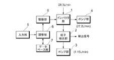
図13は、上記比較例のバーチャルインパクタを用いた粒子検出装置の構成例を説明するブロック図である。粒子検出装置は、バーチャルインパクタ(粒子濃縮装置)91、粒子検出部92、レギュレータ部93、ポンプ部94によって構成されている。気中の粒子はバーチャルインパクタ91によって濃縮されて分散光式の粒子検出部92に供給され、気体(副流)中の無機粒子や微生物粒子等を検出される。粒子検出部92内には図示しないエアポンプが内蔵されており、検査対象の気体を内部に吸引して検査済みの気体を外部に排気する。バーチャルインパクタ91で分離された気体(主流)は、排気圧を調整するレギュレータ93及び空気ポンプ94を経て排気される。 FIG. 13 is a block diagram illustrating a configuration example of a particle detection apparatus using the virtual impactor of the comparative example. The particle detection device includes a virtual impactor (particle concentration device) 91, a
このような構成によって、例えば、バーチャルインパクタ91に流入空気28.3[リットル/分]が導入されると、粒子が濃縮された副流1.15〔リットル/分〕が粒検出部92に導入され、粒子が除去された主流27.2〔リットル/分〕が排気される。よって、粒子検出部92は流入空気28.3[リットル/分]に相当する粒子検出を1.15〔リットル/分〕の気体で行うことになり、検出効率が良い。 With such a configuration, for example, when inflow air 28.3 [liter / minute] is introduced into the
(実施例)
上述した比較例の構成では、バーチャルインパクタ部91から吸引する気体の量を一定量とするためエアポンプの他に流量を調節するレギュレータを使用している(図13参照)。実施例では、このレギュレータ部93の機能をバーチャルインパクタ部91に持たせて、レギュレータ部93を不要とする。(Example)
In the configuration of the comparative example described above, a regulator that adjusts the flow rate is used in addition to the air pump in order to keep the amount of gas sucked from the
本発明のバーチャルインパクタ(粒子濃縮装置)は、サンプリングした浮遊粒子を含む気体が通過する流路の幅W1、及び粒子を含まない(粒子数が少ない)気体を排気する流路の幅S、粒子を含む(粒子数が多い)気体を排気する流路の幅W2、を適宜に調整できるようにした可変幅構造を有し、これにより、処理流量を調整することができるようにする。より具体的には、流路を構成する構成部品の位置を変化させることにより各流路の最小幅部分(例えば、ノズル部分)を調整可能とする。
なお、本発明のバーチャルインパクタは粒子を大きさで分別する場合にも使用することができる。この場合、第1の大きさに分類されるべき粒子を含む気体が通過する流路及び第2の大きさに分類されるべき粒子を含む気体が通過する流路の各流路を構成する構成部品の位置を変化させることにより各流路の幅を変化させる。The virtual impactor (particle concentrator) of the present invention includes a width W1 of a flow path through which a gas containing sampled suspended particles passes, and a width S of a flow path for exhausting a gas not containing particles (the number of particles is small), It has a variable width structure in which the width W2 of the flow path for exhausting the gas containing particles (the number of particles) can be adjusted as appropriate, and the process flow rate can be adjusted. More specifically, the minimum width portion (for example, the nozzle portion) of each flow path can be adjusted by changing the positions of the components constituting the flow path.
The virtual impactor of the present invention can also be used when particles are sorted by size. In this case, the structure which comprises each flow path of the flow path through which the gas containing the particle | grains which should be classified into the 1st size passes, and the flow path through which the gas containing the particle | grains which should be classified into the 2nd magnitude | size passes. The width of each flow path is changed by changing the position of the part.
(実施例1)
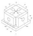
図1は、本発明の実施形態に係る可変流路幅のバーチャルインパクタの外観構成を説明する斜視図である。この例では、手操作によって流路幅を調整できるように構成している。なお、作図上の便宜から天板140を透明として内部が見えるように表示している。
同図に示すバーチャルインパクタ1(粒子濃縮装置)は、概略、4つの流路構成部材111〜114と、4つのネジ121〜124と、4つの側板131〜134と、天板140と、底板150と、を具備する。4つの流路構成部材111〜114は「田」の字状に配置され、中央部の4つ部材の角部が近接する部分は流路の交差部100となっている。交差部100では、第1の流路と第2の流路が交差する。例えば、図の右上から左下に向かってサンプリングした浮遊粒子(検体微粒子)を含む気体が通過する第1の流路が設定される。第1の流路の入口は側板131の貫通孔131a、その出口は側板134の貫通孔134aとなっている。また、図の左上が右下に向かって第1の流路と交差して第1の流路の気体の一部の排気(吸い出し)を行う第2の流路が設定される。第2の流路の一方の排気口は側板132の貫通孔132aとなっている。また、第2の流路の他方の排気口は側板133の貫通孔133aとなっている。Example 1
FIG. 1 is a perspective view illustrating an external configuration of a virtual impactor having a variable flow path width according to an embodiment of the present invention. In this example, the channel width can be adjusted manually. For convenience of drawing, the
The virtual impactor 1 (particle concentrating device) shown in the figure is roughly composed of four
交差部100では流路構成部材111〜114相互間が接近して流路が狭くなっており、交差部100から離れたところでは流路が広くなっている。流路が狭くなっている部分(隙間部)はいわゆるノズルとして機能する。例えば、流路構成部材111と112とが構成する隙間部は噴射ノズルに相当する。流路構成部材113と114とが構成する隙間部は対向ノズルに相当する。流路構成部材111及び112と流路構成部材113及び114とが構成する隙間部は噴射ノズルと対向ノズルのギャップ(離間距離)に相当する。 At the
図1に示すバーチャルインパクタ1は、概略、立方体状の外形をしている。尤もこの形状に限定されるものではない。4つの流路構成部材111〜114の周囲を囲む側板131〜134の各々には気体の流路を外部に導出する貫通孔が形成されている。4つの流路構成部材111〜114は、第1及び第2の流路の側壁を形成しており、手動で操作・調整できる流路構成部材間の距離によって各流路の幅が設定される。各流路構成部材111〜114の配置位置が決定されると流路構成部材111〜114は側板131〜134に示されるネジ穴部分で側板にネジ(図示せず)によって固定される。組み立てられた流路構成部材111〜114及び側板131〜134に天板及び底板150が取り付けられる。なお、底板150の一部は摺動(スライド)可能に構成され、調整の便宜が図られる。 The
バーチャルインパクタ1の組み立て後の流路幅の調整は、例えば、図1に示す、天板140と底板150とを流路構成部材111〜1114に密着させる4つのネジ121〜124を適宜に緩め、調整の対象となる流路構成部材を側板に固定しているネジを緩めて流路幅の調整を行う。調整後は各ネジを締める。ユーザは、このようにして、手動により流路構成部材の位置を微調整して交差部100の各流路の幅(流体の断面積)を設定・調整して、必要な所定の各流路幅を実現することができる。
なお、手作業による調整の際、ギャップを設定するシムゲージや適当な工具を使用して調整の容易化が図られているが、後述の実施例のように予めギャップを機械的な可変構造(例えば、ネジによる部材の進退構造、カム機構など)とすると調整がより容易になる。The adjustment of the flow path width after the assembly of the
In addition, in manual adjustment, adjustment is facilitated by using a shim gauge for setting the gap or an appropriate tool. However, the gap is mechanically variable in advance (for example, as in the embodiments described later). The adjustment can be made easier by using a screw advance / retreat structure, a cam mechanism, or the like.
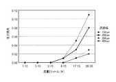
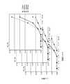
図2は、バーチャルインパクタ1の主流量について流量対圧力損失特性を複数の(主流量の)流路幅Sについて計測した例である。副流の流量は主流の流量に比べて流量が十分に少ない量であるので影響は少ない(図13の参考例の流量参照)。図2において、菱形のサンプリング点のグラフは流路幅Sを150μmに設定した例、四角形のサンプリング点のグラフは流路幅Sを200μmに設定した例、三角形のサンプリング点のグラフは流路幅Sを300μmに設定した例、バツ印形のサンプリング点のグラフは流路幅Sを400μmに設定した例である。なお、サンプリング点が重なる部分は広い流路のサンプリング点で表示している。このグラフより、概略、以下のようなことが判る。参考例のように流量が5〔リットル/分〕以下のような少ない場合(例えば、副流の流量が該当する)には、いずれの流路幅でも圧力損失は生じない。流量が9〔リットル/分〕を超えると流路の幅が400μmよりも狭いと圧損が生じ始める。そして、参考例の主流の流量に相当する、流量が主流に相当する27〔リットル/分〕程度の流量範囲では主流の流路幅Sの減少に対応して圧力損失が発生する。よって、バーチャルインパクタ1の流路構成部材の位置調整によって主流の流路幅を変えることによって主流の流量を調整・設定することが可能であることが判る。 FIG. 2 is an example in which the flow rate vs. pressure loss characteristic is measured for a plurality of (main flow rate) channel widths S for the main flow rate of the
上述したように、バーチャルインパクタ1の構造はバーチャルインパクタのノズル間ギャップ部(図12参照)に相当する交差部100が主流と副流の2つの流路の交差部として構成されるので、副流(小流量)に対してバーチャルインパクタの噴射ノズル及び対向ノズルとして機能し、主流(大流量)に対して流路の絞り(流路幅制限)として機能する。このため、バーチャルインパクタ1を一定の流量範囲で主流のレギュレータとして機能させることが可能であり、それにより既述レギュレータ部93を省略することが可能となる。実施例のバーチャルインパクタ1は従来バーチャルインパクタと異なって流路幅が可変構造であり、使用者による調整が可能である。 As described above, the structure of the
(実施例2)
図3は、流路幅を自動的に調整可能としたバーチャルインパクタの第2の実施例を示す斜視図である。同図において図1と対応する部分には同一符号を付し、かかる部分の説明は省略する。図3に示す例においては、インパクタバーチャルインパクタ1の天板140を外した状態で示している。
この実施例では、側板131、132、及び134内に流路構成部材111〜114の移動機構が設けられている。移動機構は制御装置におけるアクチュータに相当する。(Example 2)
FIG. 3 is a perspective view showing a second embodiment of the virtual impactor in which the flow path width can be automatically adjusted. In the figure, parts corresponding to those in FIG. 1 are denoted by the same reference numerals, and description thereof will be omitted. In the example shown in FIG. 3, the
In this embodiment, movement mechanisms for the
図4は、移動機構の要部を説明する説明図であり、図3のバーチャルインパクタを上方から見た状態で示している。バーチャルインパクタ1の基本フレームとなる底板150上の上側半分の領域に第1のサブフレーム152が固定配置され、下側半分の領域に第2のサブフレーム154が上下方向(図中のy方向)に移動可能に配置される。サブフレーム154の移動は底板150上の摺動路(図示せず)に沿って行われる。第1のサブフレーム152の左側領域に流路構成部材111が配置され、右側領域に流路構成部材112が配置される。例えば、流路構成部材111はサブフレーム152に固定され、流路構成部材112はサブフレーム152上の摺動路(図示せず)に沿って左右方向(図中のx方向)に移動可能に取り付けられる。第2のサブフレーム154の左側領域に流路構成部材113が配置され、右側領域に流路構成部材114が配置される。例えば、流路構成部材113及び流路構成部材114はサブフレーム154上の摺動路(図示せず)に沿って左右方向(図中のx方向)に移動可能に取り付けられる。 FIG. 4 is an explanatory diagram for explaining a main part of the moving mechanism, and shows the virtual impactor of FIG. 3 as viewed from above. The
流路構成部材113及び流路構成部材114相互間に移動機構161が接続され、流路構成部材113及び流路構成部材114相互間は接近したり、離間したりするように動作する。流路構成部材111及び流路構成部材112相互間に移動機構162が接続され、流路構成部材111に流路構成部材112が接近したり、離間したりするように動作する。
また、第1のサブフレーム152と第2のサブフレーム154の相互間が移動機構163によって接続される。移動機構163の動作によってサブフレーム152にサブフレーム154が接近したり、離間したりするように動作する。移動機構161〜163は、モータ、ポテンショメータ、送りネジ、フレーム固定ナットなどによって構成され、外部から供給される電気信号によってモータの回転角が制御されてサブフレーム154や流路構成部材112〜114の移動量が調整・設定される。微小変位を与えるアクチュータ(移動機構)としては、印加電圧に対応した形状歪み変位を発生する圧電体、油圧(流体)モータ、シリンダ等を使用するものであっても良い。The
Further, the moving
図4に示すように、流路構成部材111及び112と流路構成部材113及び114との相互間に設定される主流の流路幅S(あるいはサブフレーム152と154との隙間S)は移動機構163の動作によって設定される。また、流路構成部材111及び112相互間に設定される気体供給流路の幅W1は移動機構162によって調整・設定される。流路構成部材113及び114相互間に副流の流路の幅W2は移動機構163の動作によって設定される。As shown in FIG. 4, the mainstream channel width S (or the gap S between the
(実施例3)
図5は、他の実施例を示している。同図において、図4と対応する部分には同一符号を付し、かかる部分の説明は省略する。
この例では、図12に示すようなノズルの断面と類似の形状の流路構成部材111〜114が基板に取り付けられ、当該基板の部分に移動機構が接続されている。このような構成であっても、流路の幅を調整することができる。Example 3
FIG. 5 shows another embodiment. In the figure, parts corresponding to those in FIG. 4 are denoted by the same reference numerals, and description thereof will be omitted.
In this example, flow
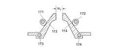
(実施例4)
図6は、他の実施例を示している。この実施例では、図示しないモータによって回転角度駆動されるカム機構171、172によって流路構成部材113、114が支点173,175を中心に揺動することによって流路構成部材113,114間の流路幅を調整・設定する構成としている。
このようにして、バーチャルインパクタの主流の流路の幅や副流の流路の幅を調整することが可能となる。主流の流路の幅を調整することによって主流の流量を調整することが可能となる。また、副流の流路の幅を調整することによって分流する粒子の大きさや濃縮対象の粒子の大きさ等を調整することが可能となる。Example 4
FIG. 6 shows another embodiment. In this embodiment, the flow
In this way, it is possible to adjust the width of the main flow path and the width of the sub flow path of the virtual impactor. By adjusting the width of the main flow path, the main flow rate can be adjusted. Further, by adjusting the width of the flow path of the side flow, it is possible to adjust the size of the particles to be diverted, the size of the particles to be concentrated, and the like.
(実施例5)
図7は、上述した可変流路幅のバーチャルインパクタを備える粒子検出装置の例を説明する説明図である。この例では、いわゆるフィードフォワード方式でバーチャルインパクタの流路幅を調整している。
同図において、粒子検出装置は、上述したバーチャルインパクタ部(粒子濃縮装置)1、粒子検出部2、エアポンプ(副流を吸引する第1のポンプ)、エアポンプ4(主流を吸引する第2のポンプ)、入力部5、調整部(コンピュータ・システム)6、データベース部7、及び駆動部8等を備えて構成される。粒子検出部2は、例えば、既述WO 2010/080643号公報で開示されたような散乱光・蛍光検出式の粒子検出器であり、微粒子・微生物をリアルタイムで検出する。データベース部7は、指定される動作条件(例えば、粒子の分粒、粒子の濃縮など)を実現する各部のパラメータの値を予め記憶している。(Example 5)
FIG. 7 is an explanatory diagram illustrating an example of a particle detection apparatus including the virtual impactor having the variable flow path width described above. In this example, the flow width of the virtual impactor is adjusted by a so-called feedforward method.
In the figure, the particle detector includes a virtual impactor unit (particle concentrator) 1, a
データベース部7は、例えば、図9に示すように、各ポンプ部のエアポンプの吸入圧力[kPa]対排気流量(排気速度)〔リットル/分〕の関係を記憶しており、ポンプモータ(図示せず)への供給電力によって所定の吸入圧力値を設定すると、ポンプ単体における排気流量が設定される。これにより、ポンプ部4によってバーチャルインパクタ1の主流の流量の概略値を設定することができる。更に、バーチャルインパクタ1の流路幅Sを調整することよって主流の流量QMを調整することができる。同様に、ポンプ部3によってバーチャルインパクタ1の副流の流量を設定することができる。副流の流量Qmは全流入量QO(=QM+Qm)の、例えば、1/10以下であることが多い(これに限定されない。)。全流量が大きい場合には相対的に副流の流量による主流の流量への影響は少ない。For example, as shown in FIG. 9, the
また、データベース部7は、例えば、図10に示すように、バーチャルインパクタ1の流路幅W1,W2についての複数の条件下で流路幅Sを複数に設定した場合の流量対圧力損失特性等も多数記憶している。このようなデータを参照することによって主流の流量、副流の流量をより正確に調整・設定することが可能となる。Further, for example, as shown in FIG. 10, the
使用者はキーボードなどを含む入力部5を介して動作条件を設定する。調整部6は指定された動作条件に対応するデータベース部7に記録された各部の制御パラメータ情報を参照して駆動部8を動作させバーチャルインパクタ1部内の移動機構161から163のアクチュエータ(モータなど)を動作させて動作条件に対応するバーチャルインパクタ部1の第1の流路の幅(W1,W2)、第2の流路の幅(S)を設定する。また、エアポンプ部3、エアポンプ部4を動作させてバーチャルインパクタ1の副流、主流の流量を設定する。各部の設定によってバーチャルインパクタ部1は、例えば、粒子濃縮器として機能する。バーチャルインパクタ部1から粒子が濃縮された副流が粒子検出器2に供給され、気体中の粒子が検出される。The user sets operating conditions via the
なお、バーチャルインパクタ1(図3、図4参照)の第1の流路の幅の設定は、入力気体の噴出ノズル口の流路幅W1、対向ノズルの吸入口の流路幅W2の設定に相当する。また、第2の流路の幅の設定は、噴出ノズルと対向ノズル間のギャップ(離間距離)Sに相当する。上記第1の流路で、粒子検出部2とポンプ部3との間の圧力(但し、流路入口との差圧とする)を測定することで、該第1の流路の流量を確認することができる。同様に、上記第2の流路で、バーチャルインパクタ1とポンプ4との間の圧力(但し、流路入口との差圧とする)を測定することで、該第2の流路の流量を確認することができる。
このようにして、フィードフォワード方式でバーチャルインパクタの流路幅等が調整される。The width of the first flow path of the virtual impactor 1 (see FIGS. 3 and 4) is determined by setting the flow path width W1 of the input gas ejection nozzle port and the flow path width W2 of the suction port of the counter nozzle. Corresponds to the setting. The setting of the width of the second flow path corresponds to the gap (separation distance) S between the ejection nozzle and the counter nozzle. The flow rate of the first flow path is confirmed by measuring the pressure between the
In this way, the flow width of the virtual impactor is adjusted by the feed forward method.
(実施例6)
図8は、可変流路幅のバーチャルインパクタを備える粒子検出装置の例を説明する説明図である。この例では、いわゆるフィードバック方式でバーチャルインパクタの流路幅を既定値(目標値)に調整している。図8において図7と対応する部分には同一符号を付し、かかる部分の説明は省略する。(Example 6)
FIG. 8 is an explanatory diagram for explaining an example of a particle detection apparatus including a virtual impactor having a variable flow path width. In this example, the channel width of the virtual impactor is adjusted to a predetermined value (target value) by a so-called feedback method. 8, parts corresponding to those in FIG. 7 are denoted by the same reference numerals, and description thereof is omitted.
この実施例では、粒子検出装置は、実施例5の構成、すなわち、バーチャルインパクタ部(粒子濃縮装置)1、粒子検出部2、エアポンプ(第1のポンプ)、エアポンプ4(第2のポンプ)、入力部5、制御部(コンピュータ・システム)6、データベース部7、及び駆動部8等の構成に加えて流量/流圧検出計(以下、単に、「検出器」という。)11及び12を備えている。流路内の気体流量及び気体流の圧力(流圧)を検出する計器は市販品を使用することができる。 In this embodiment, the particle detection device has the same configuration as in
検出器11はバーチャルインパクタ1とポンプ部4との間の流路に挿入されバーチャルインパクタ1から排気される主流の流量及び流圧を検出する(検出器11は第2の検出手段に相当する。)。流量値/流圧値の検出値は電気信号(第1の検出信号)として制御部6に送信される。これにより、制御部6は、現在の主流の流量・流圧を正確に把握することができる。検出器12は粒子検出器2とポンプ部3との間の流路に挿入されバーチャルインパクタ1から排気される副流の流量及び流圧を検出する(検出器12は第1の検出手段に相当する。)。流量値/流圧値の検出値は電気信号(第2の検出信号)として制御部6に送信される。制御部6は、現在の副流の流量・流圧を正確に把握することができる。粒子検出器2はバーチャルインパクタ1から排気される副流の気体中の粒子数と、その粒子径を検出する。粒子の検出値は電気信号(第3の検出信号)として制御部6に送信される。制御部6は、現在の副流の気体中の粒子数と、その粒子径を正確に把握することができる。制御部6は、現在の副流の粒子数とその粒子径が予め副流の気体に予定されている範囲内であるか、粒子が検出されているかどうかなどを判断する。それにより、バーチャルインパクタ1の調整における適正判断の一つの指標とされる。不具合があれば、バーチャルインパクタ1を再調整の対象とする。また、外部に信号を送出してオペレータなどに注意を喚起することができる(図示せず。)。 The
制御部6は、上述した調整部の各部機構を入力条件に対応して設定する機能に加えて、一旦設定したバーチャルインパクタ1の流路幅W1、W2、Sを上述した第1及び第2の検出信号に基づいて所定条件を満たすように誤差分に応じて再調整する。また、必要により、各ポンプ部の吸入量調整も行う。制御部6は、常時第1乃至第3の検出信号を監視し、粒子検出装置における動作条件が目標状態に維持されるように制御を行う。In addition to the function of setting each mechanism of the adjusting unit corresponding to the input condition, the
以上説明したように、流路幅の決まっている(流路幅固定)バーチャルインパクタ(比較例のバーチャルインパクタ)を使用した場合には、所定流量の気体の吸引を正確に行うためにエアポンプとレギュレータが必要であるところ、実施例のように可変流路幅構成のバーチャルインパクタを使用することによってレギュレータを不要とすることが可能となる。また、レギュレータにおける圧力損失がなくなるのでその分ポンプの吸引圧力を下げ電力消費を下げることが可能となる。また、節約した電力あるいは吸引パワーを他の部分で利用することが可能となる。 As described above, when using a virtual impactor with a fixed flow path width (fixed flow path width) (a virtual impactor of a comparative example), an air pump and a regulator are used to accurately suck a predetermined flow rate of gas. However, it is possible to eliminate the need for a regulator by using a virtual impactor having a variable flow path width configuration as in the embodiment. Further, since the pressure loss in the regulator is eliminated, the suction pressure of the pump can be lowered correspondingly, and the power consumption can be reduced. Further, the saved power or suction power can be used in other parts.
また、バーチャルインパクタの副流における流路幅W1,W2、排気流量等を可変とすることによってバーチャルインパクタの粒子の大きさ(質量)の選択特性を可変にすることができる。それにより、複数のバーチャルインパクタの出力を選択する構成とせずとも1つのバーチャルインパクタで粒子の大きさを選択(分粒)することが可能となる。In addition, the selection characteristics of the particle size (mass) of the virtual impactor can be made variable by making the flow path widths W1 , W2 , the exhaust flow rate, etc. in the subflow of the virtual impactor variable. Accordingly, it is possible to select (size) the particle size with one virtual impactor without selecting the output of a plurality of virtual impactors.
実施例の可変流路幅バーチャルインパクタを使用することによってバーチャルインパクタで気体中の粒子を濃縮して粒子検出を行うことが可能となる。 By using the variable channel width virtual impactor of the embodiment, it is possible to detect particles by concentrating particles in the gas with the virtual impactor.
また、実施例の可変流路幅バーチャルインパクタを使用することによって1つのバーチャルインパクタで気体中の粒子の大きさを異なる基準値で分別することが可能になるので、基準値の異なる複数のバーチャルインパクタの出力を選択する場合と比べると、装置を安価に構成することが可能となる。 Further, by using the variable channel width virtual impactor of the embodiment, it becomes possible to classify the size of particles in the gas by different reference values with one virtual impactor, and therefore, a plurality of virtual impactors having different reference values. As compared with the case of selecting the output, it is possible to configure the apparatus at a low cost.
1 バーチャルインパクタ(粒子濃縮装置、粒子分別装置)、2 粒子検出部、3,4 ポンプ部、5 入力部、6 調整部(あるいは制御部)、7 データベース部、100 交差部、W1 噴出ノズルの出口(流路)幅、W2 対向ノズルの入口(副流の流路)幅、S 噴出ノズル及び対向ノズル間の離間距離(主流の流路幅)1 Virtual impactor (particle concentrator, particle separator), 2 particle detector, 3, 4 pump unit, 5 input unit, 6 adjustment unit (or control unit), 7 database unit, 100 crossing unit, W1 jet nozzle Outlet (flow path) width, W2 counter nozzle inlet (secondary flow path) width, S separation distance between jet nozzle and counter nozzle (main flow path width)
Claims (2)
Translated fromJapanese前記第1の流路と交差する部分を有して前記流体の一部を分岐させる第2の流路と、を備えるバーチャルインパクタであって、
前記第1の流路及び前記第2の流路の交差部で流路の幅を変化させて前記流体の断面積を所望値に設定する流路幅調整手段を備え、
前記流路幅調整手段は、
マトリクス状に配置された4つの流路構成部材と、
前記4つの流路構成部材の両面を挟持する天板及び底板と、
前記流路構成部材相互間の離間距離を設定する距離調整手段と、を備えるバーチャルインパクタ。A first flow path for flowing a fluid containing particles;
A virtual impactor comprising: a second flow path having a portion intersecting the first flow path and branching a part of the fluid;
A flow path width adjusting means for setting a cross-sectional area of the fluid to a desired value by changing a width of the flow path at an intersection of the first flow path and the second flow path;
The flow path width adjusting means includes
Four flow path components arranged in a matrix;
A top plate and a bottom plate that sandwich both surfaces of the four flow path component members;
A virtual impactor comprising: distance adjusting means for setting a separation distance between the flow path component members.
Priority Applications (2)
| Application Number | Priority Date | Filing Date | Title |
|---|---|---|---|
| JP2012245823AJP6033643B2 (en) | 2012-11-07 | 2012-11-07 | Variable channel width virtual impactor |
| US14/074,211US9146188B2 (en) | 2012-11-07 | 2013-11-07 | Variable flow path width virtual impactor and particle detecting device |
Applications Claiming Priority (1)
| Application Number | Priority Date | Filing Date | Title |
|---|---|---|---|
| JP2012245823AJP6033643B2 (en) | 2012-11-07 | 2012-11-07 | Variable channel width virtual impactor |
Publications (2)
| Publication Number | Publication Date |
|---|---|
| JP2014095571A JP2014095571A (en) | 2014-05-22 |
| JP6033643B2true JP6033643B2 (en) | 2016-11-30 |
Family
ID=50621115
Family Applications (1)
| Application Number | Title | Priority Date | Filing Date |
|---|---|---|---|
| JP2012245823AExpired - Fee RelatedJP6033643B2 (en) | 2012-11-07 | 2012-11-07 | Variable channel width virtual impactor |
Country Status (2)
| Country | Link |
|---|---|
| US (1) | US9146188B2 (en) |
| JP (1) | JP6033643B2 (en) |
Families Citing this family (13)
| Publication number | Priority date | Publication date | Assignee | Title |
|---|---|---|---|---|
| EP3435059A1 (en)* | 2017-07-27 | 2019-01-30 | Nederlandse Organisatie voor toegepast- natuurwetenschappelijk onderzoek TNO | A particle detection device and a method for detecting airborne particles |
| US11380438B2 (en) | 2017-09-27 | 2022-07-05 | Honeywell International Inc. | Respiration-vocalization data collection system for air quality determination |
| US10876949B2 (en) | 2019-04-26 | 2020-12-29 | Honeywell International Inc. | Flow device and associated method and system |
| US10794810B1 (en) | 2019-08-02 | 2020-10-06 | Honeywell International Inc. | Fluid composition sensor device and method of using the same |
| US11221288B2 (en)* | 2020-01-21 | 2022-01-11 | Honeywell International Inc. | Fluid composition sensor device and method of using the same |
| US11391613B2 (en) | 2020-02-14 | 2022-07-19 | Honeywell International Inc. | Fluid composition sensor device and method of using the same |
| US11181456B2 (en) | 2020-02-14 | 2021-11-23 | Honeywell International Inc. | Fluid composition sensor device and method of using the same |
| US11333593B2 (en) | 2020-02-14 | 2022-05-17 | Honeywell International Inc. | Fluid composition sensor device and method of using the same |
| US12111257B2 (en) | 2020-08-26 | 2024-10-08 | Honeywell International Inc. | Fluid composition sensor device and method of using the same |
| US11835432B2 (en) | 2020-10-26 | 2023-12-05 | Honeywell International Inc. | Fluid composition sensor device and method of using the same |
| KR102504962B1 (en)* | 2021-03-25 | 2023-03-02 | 울산과학기술원 | Design method of virtual impactor based on compressed flow |
| US12281976B2 (en) | 2021-05-13 | 2025-04-22 | Honeywell International Inc. | In situ fluid sampling device and method of using the same |
| DE102023202570A1 (en) | 2023-03-22 | 2024-09-26 | Robert Bosch Gesellschaft mit beschränkter Haftung | Water separator and fuel cell system |
Family Cites Families (6)
| Publication number | Priority date | Publication date | Assignee | Title |
|---|---|---|---|---|
| US5006227A (en)* | 1989-06-26 | 1991-04-09 | Msp Corporation | Volumetric flow controller for aerosol classifier |
| US5425802A (en)* | 1993-05-05 | 1995-06-20 | The United States Of American As Represented By The Administrator Of Environmental Protection Agency | Virtual impactor for removing particles from an airstream and method for using same |
| US20040038385A1 (en)* | 2002-08-26 | 2004-02-26 | Langlois Richard G. | System for autonomous monitoring of bioagents |
| JP2004089898A (en)* | 2002-09-02 | 2004-03-25 | Hyogo Prefecture | Method and apparatus for isolating suspended particle in fluid |
| WO2010080643A1 (en) | 2008-12-18 | 2010-07-15 | Biovigilant Systems, Inc. | Integrated microbial collector |
| JP5755949B2 (en) | 2010-12-14 | 2015-07-29 | シャープ株式会社 | Detection apparatus and detection method |
- 2012
- 2012-11-07JPJP2012245823Apatent/JP6033643B2/ennot_activeExpired - Fee Related
- 2013
- 2013-11-07USUS14/074,211patent/US9146188B2/ennot_activeExpired - Fee Related
Also Published As
| Publication number | Publication date |
|---|---|
| US20140123730A1 (en) | 2014-05-08 |
| JP2014095571A (en) | 2014-05-22 |
| US9146188B2 (en) | 2015-09-29 |
Similar Documents
| Publication | Publication Date | Title |
|---|---|---|
| JP6033643B2 (en) | Variable channel width virtual impactor | |
| US9541488B2 (en) | Particle sampling and measurement in the ambient air | |
| US9810558B2 (en) | Pressure-based airflow sensing in particle impactor systems | |
| JP4959975B2 (en) | Collection device, bioconcentration device, and method for collecting and concentrating biological factors | |
| WO2014115409A1 (en) | Fine particle fractionation device, fine particle fractionation method and program | |
| US6386015B1 (en) | Apparatus to collect, classify, concentrate, and characterize gas-borne particles | |
| EP3035030B1 (en) | Particle fractionation device, particle fractionation method, and program | |
| US9482620B2 (en) | Portable particle spectrometer | |
| TW201621294A (en) | Microfluidic-based real-time detector for fine particulate matter | |
| US12090478B2 (en) | Microfluidic particle analysis device | |
| US7521673B2 (en) | Wide range, very high resolution differential mobility analyzer (DMA) | |
| KR102564702B1 (en) | Fine dust sensor and its method | |
| NL2023680B1 (en) | Air sampler device for particle concentration sensor | |
| JP2003177085A (en) | Dry process grain size distribution-measuring apparatus | |
| US20090223874A1 (en) | Apparatus for particle sorting by fluidic vectoring | |
| WO2018089674A1 (en) | Particulate matter sensor | |
| JP2018521312A (en) | Particle sensor and particle sensing method | |
| Haglund et al. | A circumferential slot virtual impactor | |
| JP6876795B2 (en) | Microfabrication sorting device for particulate matter monitoring | |
| Borhani Jebeli et al. | A new cyclone design with adjustable inlet angle and external geometry for optimal PM10 removal | |
| KR100948715B1 (en) | Particle sorting method capable of controlling the target fractional particle size, particle sorting unit for performing the same, manufacturing method thereof and particle sorting apparatus | |
| CN106605091B (en) | Apparatus for controlling airflow and systems and methods for using the same | |
| JP2021185343A (en) | Multiple sampler device | |
| JP6965953B2 (en) | Microchip and fine particle analyzer | |
| Wang et al. | A Micro Aerosol Sensor for PM1 Concentration Detection Based on 3D Printed Virtual Impactor and SAW Sensor |
Legal Events
| Date | Code | Title | Description |
|---|---|---|---|
| A621 | Written request for application examination | Free format text:JAPANESE INTERMEDIATE CODE: A621 Effective date:20150916 | |
| A977 | Report on retrieval | Free format text:JAPANESE INTERMEDIATE CODE: A971007 Effective date:20160721 | |
| A131 | Notification of reasons for refusal | Free format text:JAPANESE INTERMEDIATE CODE: A131 Effective date:20160725 | |
| A521 | Request for written amendment filed | Free format text:JAPANESE INTERMEDIATE CODE: A523 Effective date:20160908 | |
| TRDD | Decision of grant or rejection written | ||
| A01 | Written decision to grant a patent or to grant a registration (utility model) | Free format text:JAPANESE INTERMEDIATE CODE: A01 Effective date:20160929 | |
| A61 | First payment of annual fees (during grant procedure) | Free format text:JAPANESE INTERMEDIATE CODE: A61 Effective date:20161026 | |
| R150 | Certificate of patent or registration of utility model | Ref document number:6033643 Country of ref document:JP Free format text:JAPANESE INTERMEDIATE CODE: R150 | |
| LAPS | Cancellation because of no payment of annual fees |