JP6033544B2 - container - Google Patents
containerDownload PDFInfo
- Publication number
- JP6033544B2 JP6033544B2JP2011271196AJP2011271196AJP6033544B2JP 6033544 B2JP6033544 B2JP 6033544B2JP 2011271196 AJP2011271196 AJP 2011271196AJP 2011271196 AJP2011271196 AJP 2011271196AJP 6033544 B2JP6033544 B2JP 6033544B2
- Authority
- JP
- Japan
- Prior art keywords
- sheet
- film
- base sheet
- container
- bag
- Prior art date
- Legal status (The legal status is an assumption and is not a legal conclusion. Google has not performed a legal analysis and makes no representation as to the accuracy of the status listed.)
- Expired - Fee Related
Links
- 238000001179sorption measurementMethods0.000claimsdescription102
- 239000003463adsorbentSubstances0.000claimsdescription96
- 230000001070adhesive effectEffects0.000claimsdescription34
- 239000000853adhesiveSubstances0.000claimsdescription30
- 239000010419fine particleSubstances0.000claimsdescription8
- 239000011148porous materialSubstances0.000claimsdescription6
- 230000000274adsorptive effectEffects0.000description40
- 238000004519manufacturing processMethods0.000description15
- 239000011248coating agentSubstances0.000description12
- 238000000576coating methodMethods0.000description12
- 230000001877deodorizing effectEffects0.000description11
- 230000000694effectsEffects0.000description11
- 238000007789sealingMethods0.000description11
- 239000000123paperSubstances0.000description10
- 230000035699permeabilityEffects0.000description9
- -1shirasu balloonChemical compound0.000description9
- 239000004698PolyethyleneSubstances0.000description8
- 239000002245particleSubstances0.000description8
- 229920000573polyethylenePolymers0.000description7
- OKTJSMMVPCPJKN-UHFFFAOYSA-NCarbonChemical compound[C]OKTJSMMVPCPJKN-UHFFFAOYSA-N0.000description6
- 230000015572biosynthetic processEffects0.000description6
- 239000007789gasSubstances0.000description6
- 239000000463materialSubstances0.000description6
- 239000003973paintSubstances0.000description6
- 239000000126substanceSubstances0.000description6
- XLYOFNOQVPJJNP-UHFFFAOYSA-NwaterChemical compoundOXLYOFNOQVPJJNP-UHFFFAOYSA-N0.000description6
- VYPSYNLAJGMNEJ-UHFFFAOYSA-NSilicium dioxideChemical compoundO=[Si]=OVYPSYNLAJGMNEJ-UHFFFAOYSA-N0.000description4
- 229910021536ZeoliteInorganic materials0.000description3
- 239000011230binding agentSubstances0.000description3
- HNPSIPDUKPIQMN-UHFFFAOYSA-Ndioxosilane;oxo(oxoalumanyloxy)alumaneChemical compoundO=[Si]=O.O=[Al]O[Al]=OHNPSIPDUKPIQMN-UHFFFAOYSA-N0.000description3
- 229920006267polyester filmPolymers0.000description3
- 239000010457zeoliteSubstances0.000description3
- 239000005909KieselgurSubstances0.000description2
- 239000000654additiveSubstances0.000description2
- 239000000440bentoniteSubstances0.000description2
- 229910000278bentoniteInorganic materials0.000description2
- SVPXDRXYRYOSEX-UHFFFAOYSA-NbentoquatamChemical compoundO.O=[Si]=O.O=[Al]O[Al]=OSVPXDRXYRYOSEX-UHFFFAOYSA-N0.000description2
- 239000000919ceramicSubstances0.000description2
- 238000000034methodMethods0.000description2
- 229920000728polyesterPolymers0.000description2
- 239000011347resinSubstances0.000description2
- 229920005989resinPolymers0.000description2
- 238000005096rolling processMethods0.000description2
- 239000000741silica gelSubstances0.000description2
- 229910002027silica gelInorganic materials0.000description2
- 238000009423ventilationMethods0.000description2
- 230000004308accommodationEffects0.000description1
- 239000004566building materialSubstances0.000description1
- 239000013256coordination polymerSubstances0.000description1
- 238000004332deodorizationMethods0.000description1
- 230000001747exhibiting effectEffects0.000description1
- 239000002655kraft paperSubstances0.000description1
- 239000005001laminate filmSubstances0.000description1
- 238000004806packaging method and processMethods0.000description1
Images


Landscapes
- Separation Of Gases By Adsorption (AREA)
- Solid-Sorbent Or Filter-Aiding Compositions (AREA)
- Bag Frames (AREA)
- Wrappers (AREA)
- Disinfection, Sterilisation Or Deodorisation Of Air (AREA)
Description
Translated fromJapanese本発明は、吸着性シート及びその製造方法、並びに、前記吸着性シートを用いた容器に関するものである。 The present invention relates to an adsorbent sheet, a method for producing the same, and a container using the adsorbent sheet.
従来から、臭気成分や水蒸気などの気体中の微粒子を吸着可能な塗料として、活性炭やゼオライトなどの多孔性物質を樹脂等のバインダーで結合した塗料が提供されている(例えば、下記特許文献1,2)。 Conventionally, as a paint capable of adsorbing fine particles in gases such as odor components and water vapor, a paint in which a porous substance such as activated carbon or zeolite is bound with a binder such as a resin has been provided (for example,
しかしながら、前記従来の塗料は、建材や家具等に塗布ローラーや塗工機で塗布しなければならず、取り扱いが不便であった。 However, the conventional paints have to be applied to building materials and furniture with an application roller or a coating machine, which is inconvenient to handle.
本発明は、このような事情に鑑みてなされたもので、臭気成分や水蒸気などの気体中の微粒子を吸着可能でありながら取り扱いが便利である部材及びその製造方法、並びに、前記部材を用いた容器を提供することを目的とする。 The present invention has been made in view of such circumstances, and a member that can adsorb fine particles in a gas such as an odor component or water vapor, and is easy to handle, and a manufacturing method thereof, and the member are used. The purpose is to provide a container.
前記課題を解決するための手段として、以下の各態様を提示する。第1の態様による吸着性シートは、ベースシートと、前記ベースシートの少なくとも一方の面に形成され、多孔性物質を含む吸着層と、を備えたものである。 The following aspects are presented as means for solving the problems. The adsorbent sheet according to the first aspect includes a base sheet and an adsorbing layer formed on at least one surface of the base sheet and containing a porous material.
この第1の態様では、多孔性物質を含む吸着層を備えているので、前記吸着層によって、臭気成分や水蒸気などの気体中の微粒子を吸着可能である。そして、前記第1の態様による吸着性シートは、吸着層がベースシートに形成されており、シートという部材として構成されているので、その取り扱いが容易になる。 In this 1st aspect, since the adsorption layer containing a porous substance is provided, fine particles in gas, such as an odor component and water vapor, can be adsorbed by the adsorption layer. And since the adsorption layer by the said 1st aspect has the adsorption layer formed in the base sheet and is comprised as a member called a sheet | seat, the handling becomes easy.
前記第1の態様において、前記多孔性物質は、活性炭、ゼオライト、シラスバルーン、ベントナイト、珪藻土、シリカゲル及びセラミクスのうちから選ばれた1種以上からなるものであってもよい。 In the first aspect, the porous material may be one or more selected from activated carbon, zeolite, shirasu balloon, bentonite, diatomaceous earth, silica gel, and ceramics.
第9の態様による吸着性シートは、前記第1乃至第8のいずれかの態様において、前記吸着層は、前記ベースシートの前記一方の面及び他方の面に形成されたものである。 In the adsorbent sheet according to the ninth aspect, in any one of the first to eighth aspects, the adsorbing layer is formed on the one surface and the other surface of the base sheet.
第2の態様による吸着性シートは、前記第1の態様において、前記吸着層は、前記ベースシートの前記一方の面の一部の領域には形成されていないものである。 The adsorbent sheet according to a second aspect is the adsorbent sheet according to the first aspect, wherein the adsorbing layer is not formed in a partial region of the one surface of the base sheet.
この第2の態様によれば、吸着層がベースシートの前記一方の面の一部の領域には形成されていないので、その領域を接着箇所とすることで、吸着層の接着特性を考慮しないで当該吸着性シートを接着することができるという利点が得られる。 According to the second aspect, since the adsorption layer is not formed in a partial area of the one surface of the base sheet, the adhesion characteristic of the adsorption layer is not taken into consideration by setting the area as an adhesion portion. The advantage that the adsorbent sheet can be adhered is obtained.
第3の態様による吸着性シートは、前記第2の態様において、前記ベースシートは、少なくとも前記一方の面側にヒートシール性を有するフィルムを有し、前記一部の領域から前記フィルムが露出したものである。 The adsorbent sheet according to a third aspect is the above-described second aspect, wherein the base sheet has a film having heat sealability on at least one of the surfaces, and the film is exposed from the partial region. Is.
この第3の態様によれば、ベースシートの前記一方の面の一部の領域から露出したベースシートを構成するフィルムが、ヒートシール性を有しているので、その領域をヒートシールによる接着箇所とすることで、当該吸着性シートのヒートシールによる接着が可能となるという利点が得られる。もっとも、この第3の態様による吸着性シートにおいて、その領域を接着箇所とする場合も、ベースシートを構成する前記フィルムを接着剤で接着してもよい。 According to the third aspect, since the film constituting the base sheet exposed from the partial region of the one surface of the base sheet has heat sealability, the region is bonded to the region by heat sealing. By doing, the advantage that the adhesion | attachment by the heat seal of the said adsorbent sheet | seat is attained is acquired. However, in the adsorptive sheet according to the third aspect, the film constituting the base sheet may be adhered with an adhesive even when the region is used as an adhesion location.
なお、前記第2及び第3の態様による吸着性シートを接着剤で接着する場合、吸着層がベースシートの前記一方の面の一部の領域には形成されていないので、吸着層が形成されていないベースシートの領域を接着箇所とすることで、ベースシートの接着箇所との関係で接着剤の種類等を選定することができ、前記吸着層との関係で接着剤の種類等を選定する必要がなくなる。このため、吸着層の接着特性を考慮する必要がなくなるので、好ましい。 When adhering the adsorbent sheets according to the second and third aspects with an adhesive, the adsorbing layer is not formed because the adsorbing layer is not formed in a partial region of the one surface of the base sheet. By setting the area of the base sheet that is not used as the bonding location, the type of adhesive can be selected in relation to the bonding location of the base sheet, and the type of adhesive etc. can be selected in relation to the adsorption layer There is no need. For this reason, it is not necessary to consider the adhesive properties of the adsorption layer, which is preferable.
第4の態様による吸着性シートは、前記第1の態様において、前記ベースシートの前記一方の面に形成された前記吸着層上に形成された、通気性を有するフィルムを備えたものである。 An adsorbent sheet according to a fourth aspect includes the air permeable film formed on the adsorption layer formed on the one surface of the base sheet in the first aspect.
この第4の態様によれば、通気性を有するフィルムが吸着層上に形成されているので、前記フィルムの通気特性によって、吸着層による吸着速度等の吸着特性を調整することができるという利点が得られる。また、通気性を有するフィルムが吸着層上に形成されているので、吸着性シートに何らかの物が触れたとしても、当該物が吸着層に直接に触れるのを防止することができるという利点も得られる。したがって、例えば、当該吸着性シートを用いて袋等の容器を構成し、その際に前記フィルムが当該容器の内側に位置するようにした場合において、その容器内に収容する収容物が吸着層に直接に触れずにすむ。このため、前記収容物が、食品などの、吸着層に直接に触れないことが好ましいような物であっても、当該容器内に収容することができる。 According to the fourth aspect, since the air-permeable film is formed on the adsorption layer, there is an advantage that the adsorption characteristics such as the adsorption speed by the adsorption layer can be adjusted by the ventilation characteristics of the film. can get. In addition, since an air permeable film is formed on the adsorption layer, even if something touches the adsorptive sheet, there is an advantage that it can be prevented from directly touching the adsorption layer. It is done. Therefore, for example, when a container such as a bag is configured using the adsorbent sheet, and the film is positioned inside the container at that time, the contents to be accommodated in the container are the adsorbed layer. Don't touch it directly. For this reason, even if it is a thing which it is preferable that the said accommodation does not touch an adsorption layer directly, such as a foodstuff, it can be accommodated in the said container.
第5の態様による吸着性シートは、前記第4の態様において、前記フィルムは、多孔性フィルムであるものである。 The adsorptive sheet according to a fifth aspect is the fourth aspect, in which the film is a porous film.
この第5の態様による吸着性シートは、前記フィルムが多孔性フィルムであるので、フィルム材料自体がポリエステルなどのように通気性を有していなくても、その多孔性により通気性が付与される。もっとも、前記第5の態様において、前記フィルムは、そのフィルム材料自体がポリエチレンなどのように通気性を有していてもよい。なお、前記第4の態様では、前記フィルムは多孔性フィルムに限らない。この場合、前記フィルムを、ポリエチレンなどのように通気性を有する材料で構成すればよい。 In the adsorptive sheet according to the fifth aspect, since the film is a porous film, even if the film material itself does not have air permeability such as polyester, the air permeability is imparted by the porosity. . But in the said 5th aspect, the film material itself may have air permeability like polyethylene etc. in the said 5th aspect. In the fourth aspect, the film is not limited to a porous film. In this case, the film may be made of a material having air permeability such as polyethylene.
第6の態様による吸着性シートは、前記第4又は第5の態様において、前記フィルムは、ヒートシール性を有するものである。 The adsorptive sheet according to the sixth aspect is the film according to the fourth or fifth aspect, wherein the film has heat sealability.
この第6の態様によれば、前記フィルムがヒートシール性を有しているので、前記フィルムによってヒートシールによる接着が可能となるという利点が得られる。もっとも、この第6の態様による吸着性シートの場合も、前記フィルムの一部を他所に接着剤で接着してもよい。なお、前記第4及び第5の態様では、前記フィルムはヒートシール性を有していなくてもよい。この場合において、当該吸着性シートを接着する必要がある場合には、前記フィルムの一部を他所に接着剤で接着すればよい。 According to the sixth aspect, since the film has heat sealability, the film can be bonded by heat seal. However, also in the case of the adsorptive sheet according to the sixth aspect, a part of the film may be adhered to another place with an adhesive. In the fourth and fifth aspects, the film may not have heat sealability. In this case, when it is necessary to adhere the adsorbent sheet, a part of the film may be adhered to another place with an adhesive.
なお、前記第4乃至第6の態様による吸着性シートを接着剤で接着する場合、前記フィルムが形成されているので、前記フィルムとの関係で接着剤の種類等を選定することができ、前記吸着層との関係で接着剤の種類等を選定する必要がなくなる。このため、吸着層の接着特性を考慮する必要がなくなるので、好ましい。 In addition, when adhering the adsorptive sheet according to the fourth to sixth aspects with an adhesive, since the film is formed, the type of adhesive or the like can be selected in relation to the film, There is no need to select the type of adhesive in relation to the adsorption layer. For this reason, it is not necessary to consider the adhesive properties of the adsorption layer, which is preferable.
前記第3又は第6の態様において、前記フィルムは、ポリエチレンフィルム又はポリエステルフィルムであってもよい。 In the third or sixth aspect, the film may be a polyethylene film or a polyester film.
第7の態様による吸着性シートは、前記第1乃至第6のいずれかの態様において、前記吸着層は、前記ベースシートの前記一方の面及び他方の面に形成されたものである。 In the adsorbent sheet according to the seventh aspect, in any one of the first to sixth aspects, the adsorbing layer is formed on the one surface and the other surface of the base sheet.
この第7の態様によれば、ベースシートの両面に吸着層が形成されているので、例えば、当該吸着性シートを丸めて靴内に入れて靴の内部を脱臭するような場合には、脱臭性能などの吸着性能をより高めることができる。また、第7の態様によれば、ベースシートの両面に吸着層が形成されているので、例えば、当該吸着性シートを用いて容器を構成するような場合には、一方の面側の吸着層が容器内部空間の粒子に対する吸着効果を発揮するとともに、他方の面側の吸着層が容器外部空間の粒子に対する吸着効果を発揮し、容器の内外に対する吸着効果を同時に得ることができる。したがって、例えば、当該吸着性シートで食品等を収容する袋を構成した場合、その食品等を収容した袋を冷蔵庫内に入れると、当該袋の内部空間に対する脱臭効果と、当該袋の外部空間である冷蔵庫内の空間に対する脱臭効果を、同時に得ることができる。また、例えば、当該吸着性シートで一足の靴を収容する靴箱を構成した場合、その一足の靴を収容した靴箱を、何足もの靴を収容する下駄箱内に入れると、当該靴箱の内部空間に対する脱臭効果と、当該靴箱の外部空間である下駄箱内の空間に対する脱臭効果を、同時に得ることができる。 According to the seventh aspect, since the adsorbing layers are formed on both surfaces of the base sheet, for example, when the adsorbing sheet is rolled and placed in the shoe to deodorize the inside of the shoe, the deodorizing is performed. Adsorption performance such as performance can be further enhanced. Further, according to the seventh aspect, since the adsorption layers are formed on both surfaces of the base sheet, for example, in the case where a container is configured using the adsorbent sheet, the adsorption layer on one surface side. Exhibits the effect of adsorbing particles in the inner space of the container, and the adsorption layer on the other side exhibits the effect of adsorbing particles in the outer space of the container, so that the effect of adsorbing the inside and outside of the container can be obtained simultaneously. Therefore, for example, when a bag containing food or the like is configured with the adsorbent sheet, when the bag containing the food or the like is placed in a refrigerator, the deodorizing effect on the internal space of the bag and the external space of the bag The deodorizing effect with respect to the space in a certain refrigerator can be acquired simultaneously. Further, for example, when a shoe box that accommodates a pair of shoes is configured by the adsorbent sheet, when the shoe box that accommodates the pair of shoes is placed in a clog box that accommodates a number of shoes, the interior space of the shoe box And the deodorizing effect on the space inside the shoe box which is the outer space of the shoe box can be obtained at the same time.
第8の態様による吸着性シートの製造方法は、前記第1乃至第7のいずれかの態様による吸着性シートを製造する方法であって、前記ベースシートの前記一方の面に前記吸着層を印刷により形成する段階を備えたものである。 The method for producing an adsorbent sheet according to an eighth aspect is a method for producing the adsorbent sheet according to any one of the first to seventh aspects, wherein the adsorbing layer is printed on the one surface of the base sheet. Is provided.
前記印刷に用いる版は、凸版、凹版、平版、孔版などいずれの版を用いてもよいが、比較的厚さの厚い印刷が容易である凹版を用いることが好ましい。前記印刷に用いるインクとしては、特に限定されるものではなく、多孔性物質を含む公知の吸着性塗料をそのまま用いてもよいし、転写特性等の印刷適正をより高めるべく、粘度やバインダーの種類や添加剤等を適宜変更してもよい。 The plate used for the printing may be any plate such as a relief plate, an intaglio plate, a lithographic plate, and a stencil plate, but it is preferable to use an intaglio plate that is relatively easy to print. The ink used for the printing is not particularly limited, and a known adsorptive paint containing a porous material may be used as it is, and the viscosity and the kind of binder to further improve the printing suitability such as transfer characteristics. And additives may be appropriately changed.
この第8の態様によれば、吸着層を印刷により形成するので、吸着層をエアナイフコーター等の塗工機を用いて塗工により形成する場合に比べて、小ロットかつ短納期の製造が可能となるとともに、吸着層の部分的な形成も容易となる。もっとも、前記第1乃至第7の態様による吸着性シートを製造する場合、吸着層をエアナイフコーター等の塗工機を用いて塗工により形成してもよい。 According to the eighth aspect, since the adsorption layer is formed by printing, it is possible to manufacture in a small lot and in a short delivery time compared to the case where the adsorption layer is formed by coating using a coating machine such as an air knife coater. In addition, partial formation of the adsorption layer is facilitated. But when manufacturing the adsorptive sheet by the said 1st thru | or 7th aspect, you may form an adsorption layer by coating using coating machines, such as an air knife coater.
第9の態様による容器は、前記第1乃至第7のいずれかの態様による記載の吸着性シートを用いて構成された容器であって、前記ベースシートの前記一方の面に形成された前記吸着層が前記容器の内部空間に連通するように、前記吸着性シートが用いられたものである。 A container according to a ninth aspect is a container configured using the absorptive sheet according to any one of the first to seventh aspects, and the adsorption formed on the one surface of the base sheet. The adsorbent sheet is used so that the layer communicates with the internal space of the container.
この第9の態様によれば、容器自体に、当該容器の内部空間に対する脱臭機能等の吸着機能を付与することができる。したがって、当該容器を開封した際の臭気を低減することができる。もっとも、前記第1乃至第7の態様によるシートは、必ずしも容器を構成するために用いる必要はなく、例えば、シートのまま任意の容器内に入れたり靴の中に入れたりして容器内や靴内などを脱臭したり、当該シートを壁紙等として構成してもよい。 According to the ninth aspect, an adsorption function such as a deodorizing function for the internal space of the container can be imparted to the container itself. Therefore, the odor at the time of opening the said container can be reduced. However, the sheets according to the first to seventh aspects are not necessarily used to form a container. For example, the sheet may be placed in an arbitrary container or in a shoe as it is in a container or in a shoe. The inside may be deodorized, or the sheet may be configured as wallpaper or the like.
第10の態様による容器は、前記第2又は第3の態様による吸着性シートを用いて構成された容器であって、前記ベースシートの前記一方の面に形成された前記吸着層が前記容器の内部空間に連通するように、前記吸着性シートが用いられ、前記一部の領域から露出した前記フィルムの一部が、他の箇所に、接着剤で接着されるかあるいはヒートシールされたものである。 A container according to a tenth aspect is a container configured using the adsorptive sheet according to the second or third aspect, wherein the adsorption layer formed on the one surface of the base sheet is the container. The adsorbent sheet is used so as to communicate with an internal space, and a part of the film exposed from the part of the region is adhered to another part with an adhesive or heat sealed. is there.
この第10の態様によれば、前記第9の態様と同様の利点が得られる。また、この第10の態様によれば、前記一部の領域から露出した前記フィルムの一部が接着剤で接着されるかあるいはヒートシールされているので、吸着層の接着特性と無関係に当該吸着性シートの接着を実現することができる。 According to the tenth aspect, the same advantages as in the ninth aspect can be obtained. Further, according to the tenth aspect, since the part of the film exposed from the part of the region is adhered with an adhesive or heat sealed, the adsorption is performed regardless of the adhesion characteristic of the adsorption layer. Adhesive sheet can be realized.
第11の態様による容器は、前記第6の態様による吸着性シートを用いて構成された容器であって、前記ベースシートの前記一方の面に形成された前記吸着層が前記容器の内部空間に連通するように、前記吸着性シートが用いられ、前記フィルムの一部が他の箇所にヒートシールされたものである。 A container according to an eleventh aspect is a container configured using the adsorptive sheet according to the sixth aspect, wherein the adsorption layer formed on the one surface of the base sheet is formed in the internal space of the container. The adsorbent sheet is used so as to communicate, and a part of the film is heat-sealed at another location.
この第11の態様によれば、前記第9の態様と同様の利点が得られる。また、この第11の態様によれば、前記吸着性シートが用いられ、前記フィルムの一部が他の箇所にヒートシールされているので、吸着層に対する直接のヒートシールが困難であるにも拘わらず、当該吸着性シートのヒートシールによる接着を実現することができる。 According to the eleventh aspect, the same advantages as in the ninth aspect can be obtained. Further, according to the eleventh aspect, since the adsorptive sheet is used and a part of the film is heat-sealed to another part, it is difficult to directly heat-seal the adsorbing layer. It is possible to realize adhesion by heat sealing of the adsorbent sheet.
第12の態様による容器は、前記第7の態様による吸着性シートを用いて構成された容器であって、前記ベースシートの前記一方の面に形成された前記吸着層が前記容器の内部空間に連通するとともに、前記ベースシートの前記他方の面に形成された前記吸着層が前記容器の外部空間に連通するように、前記吸着性シートが用いられたものである。 A container according to a twelfth aspect is a container configured using the absorptive sheet according to the seventh aspect, wherein the adsorption layer formed on the one surface of the base sheet is formed in the internal space of the container. The adsorbent sheet is used so that the adsorbing layer formed on the other surface of the base sheet communicates with the external space of the container while communicating.
この第12の態様によれば、前記第7の態様に関連して説明したように、一方の面側の吸着層が容器内部空間の粒子に対する吸着効果を発揮するとともに、他方の面側の吸着層が容器外部空間の粒子に対する吸着効果を発揮し、容器の内外に対する吸着効果を同時に得ることができる。 According to the twelfth aspect, as described in relation to the seventh aspect, the adsorption layer on one surface side exhibits an adsorption effect on particles in the inner space of the container, and the adsorption on the other surface side. The layer exerts an adsorption effect on the particles in the outer space of the container and can simultaneously obtain an adsorption effect on the inside and outside of the container.
なお、前記第9乃至第12の態様による容器の具体例としては、袋や箱を挙げることができるが、これらに限定されるものではない。 Specific examples of the containers according to the ninth to twelfth aspects include bags and boxes, but are not limited thereto.
本発明によれば、臭気成分や水蒸気などの気体中の微粒子を吸着可能でありながら取り扱いが便利である部材及びその製造方法、並びに、前記部材を用いた容器を提供することができる。 ADVANTAGE OF THE INVENTION According to this invention, the member which can adsorb | suck the fine particles in gas, such as an odor component and water vapor | steam, and its manufacturing method, its manufacturing method, and the container using the said member can be provided.
以下、本発明による吸着性シート及びその製造方法並びに容器について、図面を参照して説明する。 Hereinafter, an adsorptive sheet according to the present invention, a manufacturing method thereof, and a container will be described with reference to the drawings.
[第1の実施の形態]
図1は、本発明の第1の実施の形態による吸着性シート1を模式的に示す概略断面図である。[First Embodiment]
FIG. 1 is a schematic cross-sectional view schematically showing an
本実施の形態による吸着性シート1は、ベースシート2と、ベースシート2の一方の面(図1中の上面)に形成された吸着層3と、を備えている。 The
本実施の形態では、ベースシート2は、クラフト紙等の紙11で構成されている。もっとも、ベースシート2は、紙11に限らず、例えば、合成紙、樹脂フィルム、ラミネートフィルム等を用いることができる。ベースシート2は、可撓性を持つシートのみならず、厚紙等の比較的合成の高いシートであってもよい。 In the present embodiment, the
吸着層3は、多孔性物質を有し、臭気成分や水蒸気などの気体中の微粒子を吸着可能な層である。前記多孔性物質は、例えば、活性炭、ゼオライト、シラスバルーン、ベントナイト、珪藻土、シリカゲル及びセラミクスのうちから選ばれた1種以上からなる。 The
吸着層3は、例えば、多孔性物質を含む公知の吸着性塗料を塗布した層であってもよい。また、吸着層3は、例えば、多孔性物質を含むインクを印刷した層であってもよい。この印刷に用いるインクとしては、特に限定されるものではなく、多孔性物質を含む公知の吸着性塗料をそのまま用いてもよいし、転写特性等の印刷適正をより高めるべく、粘度やバインダーの種類や添加剤等を適宜変更してもよい。 The
本実施の形態では、吸着層3は、ベースシート2の上面の全面に形成されている。 In the present embodiment, the
本実施の形態による吸着性シート1は、ベースシート2の上面に吸着層3を、塗布ローラーやエアナイフコーター等の塗工機を用いて塗工により形成する段階(塗工による吸着層3の形成段階)を行うことによって、製造することができる。あるいは、本実施の形態による吸着性シート1は、ベースシート2の上面に吸着層3を、印刷により形成する段階(印刷による吸着層3の形成段階)を行うことによって、製造することができる。前記印刷に用いる版は、凸版、凹版、平版、孔版などいずれの版を用いてもよいが、比較的厚さの厚い印刷が容易である凹版を用いることが好ましい。印刷により吸着層3を形成する場合、複数回印刷を重ねることで、吸着層3を厚くしてもよい。後述する各実施の形態による吸着性シートを製造する場合にも、塗工による吸着層3の形成段階又は印刷による吸着層3の形成段階が行われる。 The
印刷による吸着層3の形成段階では、吸着層3を印刷により形成するので、吸着層3をエアナイフコーター等の塗工機を用いて塗工により形成する場合に比べて、小ロットかつ短納期の製造が可能となるので、好ましい。また、吸着層3を印刷により形成すると、吸着層3の部分的な形成も容易となる。したがって、後述する第2、第3、第7及び第8の実施の形態による吸着性シート21,31,71,81(吸着層3が一部の領域Rに形成されない吸着性シート)の製造において、印刷による吸着層3の形成段階を採用することが、特に好ましい。 In the formation stage of the
本実施の形態による吸着性シート1では、多孔性物質を含む吸着層3を備えているので、吸着層3によって、臭気成分や水蒸気などの気体中の微粒子を吸着可能である。そして、本実施の形態による吸着性シート1は、吸着層3がベースシート2に形成されており、シートという部材として構成されているので、その取り扱いが容易になる。 Since the
本実施の形態による吸着性シート1は、脱臭効果等を望む箇所に、設置すればよい。例えば、本実施の形態による吸着性シート1は、所定の大きさにして丸めて靴内に入れて靴の内部を脱臭することができる。また、本実施の形態による吸着性シート1は、例えば、壁紙等として用いることもできる。 What is necessary is just to install the
[第2の実施の形態]
図2は、本発明の第2の実施の形態による吸着性シート21を模式的に示す概略断面図である。図2において、図1中の要素と同一又は対応する要素には同一符号を付し、その重複する説明は省略する。[Second Embodiment]
FIG. 2 is a schematic cross-sectional view schematically showing the
本実施の形態による吸着性シート21が前記第1の実施の形態による吸着性シート1と異なる所は、前記第1の実施の形態では、吸着層3がベースシート2の上面の全面に形成されているのに対し、本実施の形態では、吸着層3がベースシート2の上面の一部の領域Rには形成されていない点である。 The difference between the
本実施の形態によれば、前記第1の実施の形態と同様の利点が得られる。また、本実施の形態によれば、吸着層3がベースシート2の上面の一部の領域Rには形成されていないので、その領域Rを接着剤による接着箇所とすることで、吸着層3の接着特性を考慮しないで当該吸着性シート21を接着することができるという利点が得られる。 According to the present embodiment, the same advantages as those of the first embodiment can be obtained. Moreover, according to this Embodiment, since the
[第3の実施の形態]
図3は、本発明の第2の実施の形態による吸着性シート31を模式的に示す概略断面図である。図3において、図2中の要素と同一又は対応する要素には同一符号を付し、その重複する説明は省略する。[Third Embodiment]
FIG. 3 is a schematic cross-sectional view schematically showing the
本実施の形態による吸着性シート31が前記第2の実施の形態による吸着性シート21と異なる所は、前記第2の実施の形態では、ベースシート2が紙11のみで構成されているのに対し、本実施の形態では、ベースシート2が紙11と、その上面に形成されたヒートシール性を有するフィルム12とから構成され、領域Rからフィルム12が露出している点である。 The difference between the
ヒートシール性を有するフィルム12としては、例えば、ポリエチレンフィルム(PEフィルム)やポリエステルフィルム(CPフィルム)などを用いることができる。 As the
本実施の形態では、ベースシート2は、少なくとも上面側(吸着層3が形成される面側)にヒートシール性を有するフィルム12を有していればよく、例えば、ベースシート2をフィルム12のみで構成してもよい。 In this Embodiment, the
本実施の形態によれば、前記第2の実施の形態と同様の利点が得られる。また、本実施の形態によれば、ベースシート2の上面の一部の領域Rから露出したベースシート2を構成するフィルム12がヒートシール性を有しているので、その領域Rをヒートシールによる接着箇所とすることで、当該吸着性シート31のヒートシールによる接着が可能となるという利点が得られる。もっとも、本実施の形態による吸着性シート31において、その領域Rを接着箇所とする場合も、ベースシート2を構成するフィルム12を接着剤で接着してもよい。 According to the present embodiment, advantages similar to those of the second embodiment can be obtained. Moreover, according to this Embodiment, since the
なお、本実施の形態による吸着性シート31や前記第2の実施の形態による吸着性シート21を接着剤で接着する場合、吸着層3がベースシート2の上面の一部の領域Rには形成されていないので、吸着層3が形成されていないベースシート2の領域Rを接着箇所とすることで、ベースシート2の接着箇所との関係で接着剤の種類等を選定することができ、吸着層3との関係で接着剤の種類等を選定する必要がなくなる。このため、吸着層3の接着特性を考慮する必要がなくなるので、好ましい。 When adsorbing the adsorbing
[第4の実施の形態]
図4は、本発明の第4の実施の形態による吸着性シート41を模式的に示す概略断面図である。図4において、図1中の要素と同一又は対応する要素には同一符号を付し、その重複する説明は省略する。[Fourth Embodiment]
FIG. 4 is a schematic cross-sectional view schematically showing the
本実施の形態による吸着性シート41が前記第1の実施の形態による吸着性シート1と異なる所は、本実施の形態では、吸着層3の上に、通気性を有するフィルムとして材料自体が通気性を有するフィルム42が形成されている点である。本実施の形態では、フィルム42としてヒートシール性を有するフィルムが用いられ、例えばポリエチレンフィルムが用いられている。 The difference between the
本実施の形態によれば、前記第1の実施の形態と同様の利点が得られる。また、本実施の形態によれば、通気性を有するフィルム42が吸着層3上に形成されているので、フィルム42の通気特性によって、吸着層3による吸着速度等の吸着特性を調整することができるという利点が得られる。また、通気性を有するフィルム42が吸着層3上に形成されているので、吸着性シート41に何らかの物が触れたとしても、当該物が吸着層3に直接に触れるのを防止することができるという利点も得られる。したがって、例えば、後述する第14の実施の形態による袋141のように、当該吸着性シート41を用いて袋等の容器を構成し、その際にフィルム42が当該容器の内側に位置するようにした場合において、その容器内に収容する収容物が吸着層3に直接に触れずにすむ。このため、前記収容物が、食品などの、吸着層3に直接に触れないことが好ましいような物であっても、当該容器内に収容することができる。 According to the present embodiment, the same advantages as those of the first embodiment can be obtained. Further, according to the present embodiment, since the air-
また、本実施の形態によれば、フィルム42がヒートシール性を有しているので、フィルム42によってヒートシールによる接着が可能となるという利点が得られる。もっとも、本実施の形態による吸着性シート41の場合も、フィルム42の一部を他所に接着剤で接着してもよい。なお、本実施の形態では、フィルム42は、ヒートシール性を有していなくてもよい。この場合において、当該吸着性シート41を接着する必要がある場合には、フィルム42の一部を他所に接着剤で接着すればよい。 Moreover, according to this Embodiment, since the
なお、本実施の形態による吸着性シートを接着剤で接着する場合、フィルム42が形成されているので、フィルム42との関係で接着剤の種類等を選定することができ、吸着層3との関係で接着剤の種類等を選定する必要がなくなる。このため、吸着層3の接着特性を考慮する必要がなくなるので、好ましい。 In addition, when adhering the adsorptive sheet according to the present embodiment with an adhesive, since the
[第5の実施の形態]
図5は、本発明の第5の実施の形態による吸着性シート51を模式的に示す概略断面図である。図5において、図4中の要素と同一又は対応する要素には同一符号を付し、その重複する説明は省略する。[Fifth Embodiment]
FIG. 5 is a schematic cross-sectional view schematically showing an
本実施の形態による吸着性シート51が前記第4の実施の形態による吸着性シート41と異なる所は、本実施の形態では、吸着層3の上に、通気性を有するフィルムとして、フィルム42に代えて多孔性フィルム52が形成されている点である。 The difference between the
多孔性フィルム52は、多数の微細な孔52aが形成され、その多孔性により通気性を有している。よって、多孔性フィルム52のフィルム材料自体がポリエステルなどのように通気性を有していなくても、その多孔性により通気性が付与される。もっとも、多孔性フィルム52は、そのフィルム材料自体がポリエチレンなどのように通気性を有していてもよい。多孔性フィルム52としては、公知の種々の多孔性フィルムを用いることができ、例えば、特公平6−61858号公報に開示された製造方法により製造されたフィルムを用いることができる。 The
本実施の形態では、多孔性フィルム52としてヒートシール性を有するフィルムが用いられ、例えば、ポリエステルフィルム又はポリエチレンフィルムが用いられている。 In the present embodiment, a film having heat sealing properties is used as the
本実施の形態によれば、前記第4の実施の形態と同様の利点が得られる。 According to the present embodiment, the same advantages as in the fourth embodiment can be obtained.
[第6乃至第10の実施の形態]
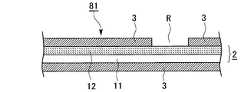
図6は、本発明の第6の実施の形態による吸着性シート61を模式的に示す概略断面図である。図7は、本発明の第7の実施の形態による吸着性シート71を模式的に示す概略断面図である。図8は、本発明の第8の実施の形態による吸着性シート81を模式的に示す概略断面図である。図9は、本発明の第9の実施の形態による吸着性シート91を模式的に示す概略断面図である。図10は、本発明の第10の実施の形態による吸着性シート71を模式的に示す概略断面図である。図6乃至図10において、図1乃至図5中の要素と同一又は対応する要素には同一符号を付し、その重複する説明は省略する。[Sixth to Tenth Embodiments]
FIG. 6 is a schematic sectional view schematically showing an
第6乃至第10の実施の形態による吸着性シート61,71,81,91,101は、それぞれ前記第1乃至第5の実施の形態による吸着性シート1,21,31,41,51において、ベースシート2の下面にも吸着層3を形成したものである。 The
第6乃至第10の実施の形態によれば、前記第1乃至第5の実施の形態とそれぞれ同様の利点が得られる。また、第6乃至第10の実施の形態によれば、ベースシート2の両面に吸着層3が形成されているので、例えば、当該吸着性シート61,71,81,91,101を丸めて靴内に入れて靴の内部を脱臭するような場合には、脱臭性能などの吸着性能をより高めることができる。さらに、第6乃至第10の実施の形態によれば、ベースシート2の両面に吸着層3が形成されているので、例えば、後述する第16乃至第20の実施の形態による袋161,171,181,191,201のように、当該吸着性シート61,71,81,91,101を用いて容器を構成するような場合には、一方の面側の吸着層3が容器内部空間の粒子に対する吸着効果を発揮するとともに、他方の面側の吸着層3が容器外部空間の粒子に対する吸着効果を発揮し、容器の内外に対する吸着効果を同時に得ることができる。したがって、例えば、当該吸着性シートで食品等を収容する袋を構成した場合、その食品等を収容した袋を冷蔵庫内に入れると、当該袋の内部空間に対する脱臭効果と、当該袋の外部空間である冷蔵庫内の空間に対する脱臭効果を、同時に得ることができる。また、例えば、当該吸着性シートで一足の靴を収容する紙箱と同様の靴箱を構成した場合、その一足の靴を収容した靴箱を、何足もの靴を収容する下駄箱内に入れると、当該靴箱の内部空間に対する脱臭効果と、当該靴箱の外部空間である下駄箱内の空間に対する脱臭効果を、同時に得ることができる。 According to the sixth to tenth embodiments, advantages similar to those of the first to fifth embodiments can be obtained. In addition, according to the sixth to tenth embodiments, since the adsorption layers 3 are formed on both surfaces of the
[第11の実施の形態]
図11は、本発明の第11の実施の形態による容器としての袋(3方シール袋)111を模式的に示す表側上方から見た概略斜視図である。図12は、図11中のA−A’線に沿った概略断面図である。図12において、図3中の要素と同一又は対応する要素には同一符号を付し、その重複する説明は省略する。[Eleventh embodiment]
FIG. 11 is a schematic perspective view of a bag (three-side seal bag) 111 as a container according to an eleventh embodiment of the present invention, as viewed from the upper front side. FIG. 12 is a schematic cross-sectional view along the line AA ′ in FIG. 12, elements that are the same as or correspond to those in FIG. 3 are given the same reference numerals, and redundant descriptions thereof are omitted.
本実施の形態による袋111は、前述した図3に示す吸着性シート31からなる表側の吸着性シート31Aと、図3に示す吸着性シート31からなる裏側の吸着性シート31Bとが重ね合わされ、左辺に沿った部分112、下辺に沿った部分113及び右辺に沿った部分114がヒートシールされ、上辺に沿った部分115はヒートシールされずに上辺が開口され、いわゆる3方シール袋となっている。 In the
表側の吸着性シート31Aの吸着層3側及び裏側の吸着性シート31Bの吸着層3側が、袋111の内側に向けられている。表側の吸着性シート31Aの各部分112〜115は、図3中の領域Rに相当し、そこには吸着層3は形成されていない。裏側の吸着性シート31Bの各部分112〜115は、図3中の領域Rに相当し、そこには吸着層3は形成されていない。各部分112〜114において、表側の吸着性シート31Aのフィルム12と裏側の吸着性シート31Bのフィルム12とが対面し、その間がヒートシールにより溶着されている。部分115において、表側の吸着性シート31Aのフィルム12と裏側の吸着性シート31Bのフィルム12とが対面しているが、その間はヒートシールされていない。表側の吸着性シート31Aの吸着層3と裏側の吸着性シート31Bの吸着層3との間に、内部空間が生ずる。図12では、両吸着層3間が重なっていて、内部空間が生じていない状態で示している。 The
図13は、図3に示す吸着性シート31を本実施の形態による袋111の製造に用いられるように構成したものであって、ロール状に巻き取られたものを模式的に示す概略斜視図である。図13では、3つの袋111に相当する部分が表れている。図13において、112R,113R,114R,115Rは、表側の吸着性シート31Aの各部分112〜115にそれぞれ対応する領域(吸着層3が形成されていない領域)を示し、112R’,113R’,114R’,115R’は、裏側の吸着性シート31Bの各部分112〜115にそれぞれ対応する領域(吸着層3が形成されていない領域)を示している。 FIG. 13 is a schematic perspective view schematically showing the
吸着性シート31をロールから巻き出しながら、吸着性シート31を中心線Lで図13中で谷折りに折り曲げて重ね合わせ、領域112R及び112R’のフィルム12同士、領域113R及び113R’のフィルム12同士、並びに、領域114R及び114R’のフィルム12同士をヒートシールする。その後、各袋111に切り分ける。これにより、本実施の形態による袋111を製造することができる。 While the
本実施の形態による袋111は、給袋方式の場合には、袋の製造業者等により製造され収容物の製造業者等へ供給されるものである。そして、給袋方式の場合には、収容物の製造業者等において、袋111内に上辺の開口から収容物を入れた後に、上辺に沿った部分115をヒートシールし、収容物の使用者の手元に届く最終形態である袋詰め体が完成する。自動包装方式の場合は、収納物の製造業者等において、図13に示す吸着性シート31から図11及び図12に示す袋体を製袋しながら、収容物の充填、更には上辺に沿った部分115のヒートシールを連続して行うものである。 In the case of the bag supply method, the
本実施の形態によれば、袋111自体に、当該袋111の内部空間に対する脱臭機能等の吸着機能を付与することができる。したがって、当該袋111を開封した際の臭気を低減することができる。 According to the present embodiment, an adsorption function such as a deodorizing function for the internal space of the
[第12の実施の形態]
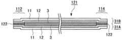
図14は、本発明の第12の実施の形態による容器としての袋(3方シール袋)121を模式的に示す概略断面図であり、図12に対応している。図14において、図12中の要素と同一又は対応する要素には同一符号を付し、その重複する説明は省略する。[Twelfth embodiment]
FIG. 14 is a schematic sectional view schematically showing a bag (three-side seal bag) 121 as a container according to the twelfth embodiment of the present invention, and corresponds to FIG. 14, elements that are the same as or correspond to those in FIG. 12 are given the same reference numerals, and redundant descriptions thereof are omitted.
本実施の形態による袋121が、前記第11の実施の形態による袋111と異なる所は、領域112R及び112R’のフィルム12同士、領域113R及び113R’のフィルム12同士、並びに、領域114R及び114R’のフィルム12同士が、ヒートシールに代えて、接着剤122により接着されている点である。 The
本実施の形態による袋121を製造する場合には、例えば、吸着性シート31を中心線Lで折り曲げて重ね合わせる前に、領域112R,113R,114Rに接着剤122を印刷等により形成すればよい。 In the case of manufacturing the
本実施の形態によっても、前記第11の実施の形態と同様の利点が得られる。 Also in this embodiment, the same advantages as those in the eleventh embodiment can be obtained.
[第13の実施の形態]
図15は、本発明の第13の実施の形態による容器としての袋(3方シール袋)131を模式的に示す概略断面図であり、図12に対応している。図15において、図2及び図12中の要素と同一又は対応する要素には同一符号を付し、その重複する説明は省略する。[Thirteenth embodiment]
FIG. 15 is a schematic cross-sectional view schematically showing a bag (three-side seal bag) 131 as a container according to the thirteenth embodiment of the present invention, and corresponds to FIG. 15, elements that are the same as or correspond to those in FIGS. 2 and 12 are given the same reference numerals, and redundant descriptions thereof are omitted.
本実施の形態による袋131は、前述した図2に示す吸着性シート21からなる表側の吸着性シート21Aと、図2に示す吸着性シート21からなる裏側の吸着性シート21Bとが重ね合わされ、左辺に沿った部分112、下辺に沿った部分113及び右辺に沿った部分114が接着剤132により接着され、上辺に沿った部分115(図示せず)は接着されずに上辺が開口され、いわゆる3方シール袋となっている。 In the
表側の吸着性シート21Aの吸着層3側及び裏側の吸着性シート21Bの吸着層3側が、袋131の内側に向けられている。表側の吸着性シート21Aの各部分112〜115は、図2中の領域Rに相当し、そこには吸着層3は形成されていない。裏側の吸着性シート21Bの各部分112〜115は、図2中の領域Rに相当し、そこには吸着層3は形成されていない。各部分112〜114において、表側の吸着性シート21Aの紙11と裏側の吸着性シート21Bの紙11とが対面し、その間が接着剤132により接着されている。部分115において、表側の吸着性シート21Aの紙11と裏側の吸着性シート21Bの紙11とが対面しているが、その間は接着されていない。表側の吸着性シート21Aの吸着層3と裏側の吸着性シート21Bの吸着層3との間に、内部空間が生ずる。図15では、両吸着層3間が重なっていて、内部空間が生じていない状態で示している。 The
本実施の形態によっても、前記第11の実施の形態と同様の利点が得られる。 Also in this embodiment, the same advantages as those in the eleventh embodiment can be obtained.
[第14の実施の形態]
図16は、本発明の第14の実施の形態による容器としての袋(3方シール袋)141を模式的に示す概略断面図であり、図12に対応している。図16において、図4及び図12中の要素と同一又は対応する要素には同一符号を付し、その重複する説明は省略する。[Fourteenth embodiment]
FIG. 16 is a schematic cross-sectional view schematically showing a bag (three-side sealed bag) 141 as a container according to the fourteenth embodiment of the present invention, and corresponds to FIG. 16, elements that are the same as or correspond to those in FIGS. 4 and 12 are given the same reference numerals, and redundant descriptions thereof are omitted.
本実施の形態による袋141は、前述した図4に示す吸着性シート41からなる表側の吸着性シート41Aと、図4に示す吸着性シート41からなる裏側の吸着性シート41Bとが重ね合わされ、左辺に沿った部分112、下辺に沿った部分113及び右辺に沿った部分114がヒートシールされ、上辺に沿った部分115(図示せず)はヒートシールされずに上辺が開口され、いわゆる3方シール袋となっている。 In the
表側の吸着性シート41Aのフィルム42側及び裏側の吸着性シート41Bのフィルム42側が、袋151の内側に向けられている。各部分112〜114において、表側の吸着性シート41Aのフィルム42と裏側の吸着性シート41Bのフィルム42とが対面し、その間がヒートシールにより溶着されている。部分115において、表側の吸着性シート41Aのフィルム42と裏側の吸着性シート41Bのフィルム42とが対面しているが、その間はヒートシールされていない。表側の吸着性シート41Aのフィルム42と裏側の吸着性シート41Bのフィルム42との間に、内部空間が生ずる。図16では、両フィルム42間が重なっていて、内部空間が生じていない状態で示している。 The
本実施の形態によっても、前記第11の実施の形態と同様の利点が得られる。 Also in this embodiment, the same advantages as those in the eleventh embodiment can be obtained.
[第15の実施の形態]
図17は、本発明の第15の実施の形態による容器としての袋(3方シール袋)151を模式的に示す概略断面図であり、図12に対応している。図17において、図16中の要素と同一又は対応する要素には同一符号を付し、その重複する説明は省略する。[Fifteenth embodiment]
FIG. 17 is a schematic cross-sectional view schematically showing a bag (three-side seal bag) 151 as a container according to the fifteenth embodiment of the present invention, and corresponds to FIG. 17, elements that are the same as or correspond to those in FIG. 16 are given the same reference numerals, and redundant descriptions thereof are omitted.
本実施の形態による袋151が、前記第14の実施の形態による袋141と異なる所は、部分112のフィルム42同士、部分113のフィルム42同士、並びに、部分114のフィルム42同士が、ヒートシールに代えて、接着剤152により接着されている点である。 The
本実施の形態によっても、前記第14の実施の形態と同様の利点が得られる。 Also in this embodiment, the same advantages as those in the fourteenth embodiment can be obtained.
なお、前記第14及び第15の実施の形態による袋141,151において、図4に示す吸着性シート41に代えて、図5に示す吸着性シート51を用いてもよい。この場合、図16や図17において、フィルム42が多孔性フィルム52に置き換わることになる。 In the
[第16乃至第20の実施の形態]
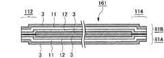
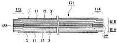
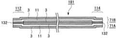
図18は、本発明の第16の実施の形態による容器としての袋(3方シール袋)161を模式的に示す概略断面図であり、図12に対応している。図19は、本発明の第17の実施の形態による容器としての袋(3方シール袋)171を模式的に示す概略断面図であり、図14に対応している。図20は、本発明の第18の実施の形態による容器としての袋(3方シール袋)181を模式的に示す概略断面図であり、図15に対応している。図21は、本発明の第19の実施の形態による容器としての袋(3方シール袋)191を模式的に示す概略断面図であり、図16に対応している。図22は、本発明の第20の実施の形態による容器としての袋(3方シール袋)201を模式的に示す概略断面図であり、図17に対応している。[Sixteenth to twentieth embodiments]
FIG. 18 is a schematic cross-sectional view schematically showing a bag (three-side sealed bag) 161 as a container according to the sixteenth embodiment of the present invention, and corresponds to FIG. FIG. 19 is a schematic sectional view schematically showing a bag (three-side seal bag) 171 as a container according to the seventeenth embodiment of the present invention, and corresponds to FIG. FIG. 20 is a schematic cross-sectional view schematically showing a bag (3-way seal bag) 181 as a container according to the eighteenth embodiment of the present invention, and corresponds to FIG. FIG. 21 is a schematic cross-sectional view schematically showing a bag (3-way seal bag) 191 as a container according to the nineteenth embodiment of the present invention, and corresponds to FIG. FIG. 22 is a schematic cross-sectional view schematically showing a bag (three-side seal bag) 201 as a container according to the twentieth embodiment of the present invention, and corresponds to FIG.
図18乃至図22において、図7乃至図9、図12、並びに図14乃至図17中の要素と同一又は対応する要素には同一符号を付し、その重複する説明は省略する。 18 to 22, the same or corresponding elements as those in FIGS. 7 to 9, 12, and 14 to 17 are denoted by the same reference numerals, and redundant description thereof is omitted.
図18に示す袋161は、図12に示す袋111において、図3に示す吸着性シート31(表側及び裏側の吸着性シート31A,31B)に代えて、図8に示す吸着性シート81(表側及び裏側の吸着性シート81A,81B)が用いられたものである。 The
図19に示す袋171は、図14に示す袋121において、図3に示す吸着性シート31(表側及び裏側の吸着性シート31A,31B)に代えて、図8に示す吸着性シート81(表側及び裏側の吸着性シート81A,81B)が用いられたものである。 The
図20に示す袋181は、図15に示す袋111において、図2に示す吸着性シート21(表側及び裏側の吸着性シート21A,21B)に代えて、図7に示す吸着性シート71(表側及び裏側の吸着性シート71A,71B)が用いられたものである。 A
図21に示す袋191は、図16に示す袋141において、図4に示す吸着性シート41(表側及び裏側の吸着性シート41A,41B)に代えて、図9に示す吸着性シート91(表側及び裏側の吸着性シート91A,91B)が用いられたものである。 The
図22に示す袋201は、図17に示す袋151において、図4に示す吸着性シート41(表側及び裏側の吸着性シート41A,41B)に代えて、図9に示す吸着性シート91(表側及び裏側の吸着性シート91A,91B)が用いられたものである。 The
これらの袋161,171,181,191,201では、一方の面側の吸着層3が袋内部空間の粒子に対する吸着効果を発揮するとともに、他方の面側の吸着層3が袋外部空間の粒子に対する吸着効果を発揮し、袋の内外に対する吸着効果を同時に得ることができる。 In these
なお、図21及び図22にそれぞれ示す袋191,201において、図9に示す吸着性シート91に代えて、図10に示す吸着性シート101を用いてもよい。この場合、図21や図22において、フィルム42が多孔性フィルム52に置き換わることになる。 Note that, in the
以上、本発明の各実施の形態について説明したが、本発明はこれらの実施の形態に限定されるものではない。 Although the embodiments of the present invention have been described above, the present invention is not limited to these embodiments.
例えば、本発明による容器は、3方シール袋以外の種々の袋や、箱などの他の形式の容器であってもよい。 For example, the container according to the present invention may be various types of bags other than a three-side seal bag, and other types of containers such as a box.
1,21,31,41,51,61,71,81,91,101 吸着性シート
2 ベース
3 吸着層
111,121,131,141,151,161,171,181,191,201 袋1, 21, 31, 41, 51, 61, 71, 81, 91, 101
Claims (9)
Translated fromJapanese前記吸着性シートは、前記ベースシートの前記一方の面に形成された前記吸着層が前記ベースシートに対して前記容器の内部空間の側に位置するとともに、前記ベースシートの前記他方の面に形成された前記吸着層が前記ベースシートに対して前記容器の外部空間の側に位置するように、用いられ、
前記ベースシートの前記一方の面に形成された前記吸着層が前記容器の前記内部空間の気体中の微粒子を吸着するとともに、前記ベースシートの前記他方の面に形成された前記吸着層が前記容器の前記外部空間の気体中の微粒子を吸着し、
当該容器は、前記内部空間内に靴が収容された状態で下駄箱内に入れられる容器であることを特徴とする容器。A container constituted by using an adsorbent sheet comprising a base sheet and an adsorbing layer formed on one surface and the other surface of the base sheet and containing a porous material,
The adsorbent sheet is formed on the other surface of the base sheet while the adsorbing layer formed on the one surface of the base sheet is positioned on the inner space side of the container with respect to the base sheet. The adsorbed layer is used so as to be located on the outer space side of the container with respect to the base sheet,
The adsorption layer formed on the one surface of the base sheet adsorbs fine particles in the gas in the internal space of the container, and the adsorption layer formed on the other surface of the base sheet is the container.adsorbing the fine particles in gas in the externalspace,
The said container is a container put in a clog box in the state in which the shoes were accommodated in the said internal space, The container characterized by the above-mentioned .
前記一部の領域から露出した前記ベースシートが、他の箇所に、接着剤で接着されたことを特徴とする請求項1記載の容器。The adsorption layer is not formed in a partial region of the one surface of the base sheet,
The container according to claim 1, wherein the base sheet exposed from the partial region is adhered to another portion with an adhesive.
前記ベースシートは、少なくとも前記一方の面側にヒートシール性を有するフィルムを有し、
前記一部の領域から露出した前記ベースシートが、他の箇所に、接着剤で接着されるかあるいはヒートシールされたことを特徴とする請求項1記載の容器。The adsorption layer is not formed in a partial region of the one surface of the base sheet,
The base sheet has a film having heat sealability on at least the one surface side,
The container according to claim 1, wherein the base sheet exposed from the partial region is adhered to another portion with an adhesive or heat sealed.
前記ベースシートの前記一方の面に形成された前記吸着層は、前記フィルムを介して前記内部空間に面することを特徴とする請求項1記載の容器。The adsorbent sheet includes a breathable film formed on the adsorbing layer formed on the one surface of the base sheet,
The container according to claim 1, wherein the adsorption layer formed on the one surface of the base sheet faces the internal space through the film.
前記フィルムの一部が他の箇所にヒートシールされるかあるいは接着剤で接着されたことを特徴とする請求項4又は5記載の容器。The film has heat sealability,
6. A container according to claim 4 or 5, wherein a part of the film is heat-sealed to another portion or bonded with an adhesive.
Priority Applications (1)
| Application Number | Priority Date | Filing Date | Title |
|---|---|---|---|
| JP2011271196AJP6033544B2 (en) | 2011-12-12 | 2011-12-12 | container |
Applications Claiming Priority (1)
| Application Number | Priority Date | Filing Date | Title |
|---|---|---|---|
| JP2011271196AJP6033544B2 (en) | 2011-12-12 | 2011-12-12 | container |
Publications (2)
| Publication Number | Publication Date |
|---|---|
| JP2013121573A JP2013121573A (en) | 2013-06-20 |
| JP6033544B2true JP6033544B2 (en) | 2016-11-30 |
Family
ID=48773883
Family Applications (1)
| Application Number | Title | Priority Date | Filing Date |
|---|---|---|---|
| JP2011271196AExpired - Fee RelatedJP6033544B2 (en) | 2011-12-12 | 2011-12-12 | container |
Country Status (1)
| Country | Link |
|---|---|
| JP (1) | JP6033544B2 (en) |
Family Cites Families (17)
| Publication number | Priority date | Publication date | Assignee | Title |
|---|---|---|---|---|
| JPS55104678U (en)* | 1979-01-29 | 1980-07-22 | ||
| JPS58124219U (en)* | 1983-01-10 | 1983-08-24 | 犬井 治 | Deodorizing sheet |
| JPS6434441A (en)* | 1987-07-29 | 1989-02-03 | Dainippon Printing Co Ltd | Water-and moisture-absorbing sheet |
| JPH01137731U (en)* | 1988-03-11 | 1989-09-20 | ||
| JPH079822Y2 (en)* | 1988-12-15 | 1995-03-08 | 中国パール販売株式会社 | Transport container |
| JP2610602B2 (en)* | 1989-08-04 | 1997-05-14 | 丸三産業株式会社 | Manufacturing method of filter media |
| JPH0563630U (en)* | 1992-02-04 | 1993-08-24 | 松下電工株式会社 | Dust removal type deodorant filter |
| JPH06340036A (en)* | 1992-11-10 | 1994-12-13 | Goyo Paper Working Co Ltd | Packing material for food container and production thereof |
| JP2003000687A (en)* | 2001-06-22 | 2003-01-07 | Daihatsu Motor Co Ltd | Deodorizing sheet, method for producing deodorizing sheet, and sheet member |
| JP2003135126A (en)* | 2001-10-31 | 2003-05-13 | Warashina Fukushikai | Footwear storage bag |
| JP2005029168A (en)* | 2003-07-07 | 2005-02-03 | Fukuoka Marumoto Kk | Shoes storage case |
| US7816285B2 (en)* | 2004-12-23 | 2010-10-19 | Kimberly-Clark Worldwide, Inc. | Patterned application of activated carbon ink |
| JP2007015698A (en)* | 2005-07-05 | 2007-01-25 | Kojima Press Co Ltd | Protective cover for seat |
| JP2007023395A (en)* | 2005-07-13 | 2007-02-01 | Tokushu Paper Mfg Co Ltd | Pollutant gas removing paper |
| JP4254812B2 (en)* | 2006-05-30 | 2009-04-15 | トヨタ紡織株式会社 | Duct and manufacturing method thereof |
| JP2008264210A (en)* | 2007-04-20 | 2008-11-06 | Shigeki Yokoyama | Powdered tea/bamboo charcoal sheet, moving body interior fixture and facility interior fixture |
| JP5549142B2 (en)* | 2008-07-30 | 2014-07-16 | ダイニック株式会社 | Adsorption filter material and air cleaner |
- 2011
- 2011-12-12JPJP2011271196Apatent/JP6033544B2/ennot_activeExpired - Fee Related
Also Published As
| Publication number | Publication date |
|---|---|
| JP2013121573A (en) | 2013-06-20 |
Similar Documents
| Publication | Publication Date | Title |
|---|---|---|
| JP2008545598A (en) | Bag with leak prevention function | |
| CA2821802A1 (en) | Flexible bag material | |
| AU2011348533A1 (en) | Flexible bag material | |
| JP2011168330A (en) | Composite container | |
| JP6487421B2 (en) | Foil wrapped vacuum insulation | |
| US20130105471A1 (en) | System and apparatus for a flexible moisture absorbent microwave package | |
| JP5911311B2 (en) | Moisture-proof bag for easy deaeration | |
| JP2024003243A (en) | packaging bag | |
| KR20150003704U (en) | Pouch container of standing type | |
| JP5174476B2 (en) | Alcohol volatilizer | |
| JP6033544B2 (en) | container | |
| JP6862408B2 (en) | Storage bag and storage bag manufacturing method | |
| EP3083436B1 (en) | Wrapper for soap bar | |
| JP2019081556A (en) | Two chamber sterilization bag | |
| JP5584485B2 (en) | Packaging for granular products | |
| JP2008213875A (en) | Multi-chamber bag and package | |
| JP5493017B2 (en) | Double packaging bag | |
| JP2012250736A (en) | Packaging bag | |
| JP3179051U (en) | Food packaging | |
| JP5492514B2 (en) | Alcohol volatilizer | |
| JP5189572B2 (en) | Double packaging bag | |
| JP2011073723A (en) | Alcoholic volatilization agent | |
| JP2008126172A (en) | Self reaction label type oxygen scavenger | |
| KR101134011B1 (en) | Porous vinyl bag and method for production thereof | |
| CN214825860U (en) | Multi-layer film preservation and anti-mold bag |
Legal Events
| Date | Code | Title | Description |
|---|---|---|---|
| A621 | Written request for application examination | Free format text:JAPANESE INTERMEDIATE CODE: A621 Effective date:20141203 | |
| A977 | Report on retrieval | Free format text:JAPANESE INTERMEDIATE CODE: A971007 Effective date:20151002 | |
| A131 | Notification of reasons for refusal | Free format text:JAPANESE INTERMEDIATE CODE: A131 Effective date:20151013 | |
| A521 | Request for written amendment filed | Free format text:JAPANESE INTERMEDIATE CODE: A523 Effective date:20151213 | |
| A131 | Notification of reasons for refusal | Free format text:JAPANESE INTERMEDIATE CODE: A131 Effective date:20160517 | |
| A521 | Request for written amendment filed | Free format text:JAPANESE INTERMEDIATE CODE: A523 Effective date:20160704 | |
| TRDD | Decision of grant or rejection written | ||
| A01 | Written decision to grant a patent or to grant a registration (utility model) | Free format text:JAPANESE INTERMEDIATE CODE: A01 Effective date:20161025 | |
| A61 | First payment of annual fees (during grant procedure) | Free format text:JAPANESE INTERMEDIATE CODE: A61 Effective date:20161026 | |
| R150 | Certificate of patent or registration of utility model | Ref document number:6033544 Country of ref document:JP Free format text:JAPANESE INTERMEDIATE CODE: R150 | |
| R250 | Receipt of annual fees | Free format text:JAPANESE INTERMEDIATE CODE: R250 | |
| R250 | Receipt of annual fees | Free format text:JAPANESE INTERMEDIATE CODE: R250 | |
| LAPS | Cancellation because of no payment of annual fees |