JP6033312B2 - Self-centered patient temperature control catheter - Google Patents
Self-centered patient temperature control catheterDownload PDFInfo
- Publication number
- JP6033312B2 JP6033312B2JP2014533634AJP2014533634AJP6033312B2JP 6033312 B2JP6033312 B2JP 6033312B2JP 2014533634 AJP2014533634 AJP 2014533634AJP 2014533634 AJP2014533634 AJP 2014533634AJP 6033312 B2JP6033312 B2JP 6033312B2
- Authority
- JP
- Japan
- Prior art keywords
- catheter
- coil
- working fluid
- patient
- heat exchange
- Prior art date
- Legal status (The legal status is an assumption and is not a legal conclusion. Google has not performed a legal analysis and makes no representation as to the accuracy of the status listed.)
- Active
Links
- 239000012530fluidSubstances0.000claimsdescription58
- 210000004204blood vesselAnatomy0.000claimsdescription32
- 230000017531blood circulationEffects0.000claimsdescription6
- 239000008280bloodSubstances0.000description10
- 210000004369bloodAnatomy0.000description10
- 238000004891communicationMethods0.000description8
- 238000010586diagramMethods0.000description6
- FAPWRFPIFSIZLT-UHFFFAOYSA-MSodium chlorideChemical compound[Na+].[Cl-]FAPWRFPIFSIZLT-UHFFFAOYSA-M0.000description5
- 239000011780sodium chlorideSubstances0.000description5
- 238000000034methodMethods0.000description4
- 239000000523sampleSubstances0.000description4
- 239000012781shape memory materialSubstances0.000description4
- 230000002631hypothermal effectEffects0.000description3
- HLXZNVUGXRDIFK-UHFFFAOYSA-Nnickel titaniumChemical compound[Ti].[Ti].[Ti].[Ti].[Ti].[Ti].[Ti].[Ti].[Ti].[Ti].[Ti].[Ni].[Ni].[Ni].[Ni].[Ni].[Ni].[Ni].[Ni].[Ni].[Ni].[Ni].[Ni].[Ni].[Ni]HLXZNVUGXRDIFK-UHFFFAOYSA-N0.000description3
- 229910001000nickel titaniumInorganic materials0.000description3
- 230000036760body temperatureEffects0.000description2
- 239000002826coolantSubstances0.000description2
- 238000001816coolingMethods0.000description2
- 239000003814drugSubstances0.000description2
- 229940079593drugDrugs0.000description2
- 238000002594fluoroscopyMethods0.000description2
- 238000003780insertionMethods0.000description2
- 230000037431insertionEffects0.000description2
- 239000003550markerSubstances0.000description2
- 239000002184metalSubstances0.000description2
- 238000001356surgical procedureMethods0.000description2
- 201000006474Brain IschemiaDiseases0.000description1
- 206010008111Cerebral haemorrhageDiseases0.000description1
- 208000010496Heart ArrestDiseases0.000description1
- 206010019280Heart failuresDiseases0.000description1
- 206010020843HyperthermiaDiseases0.000description1
- 206010037660PyrexiaDiseases0.000description1
- 229910000831SteelInorganic materials0.000description1
- 208000006011StrokeDiseases0.000description1
- 208000032851Subarachnoid HemorrhageDiseases0.000description1
- 208000030886Traumatic Brain injuryDiseases0.000description1
- 206010000891acute myocardial infarctionDiseases0.000description1
- QVGXLLKOCUKJST-UHFFFAOYSA-Natomic oxygenChemical compound[O]QVGXLLKOCUKJST-UHFFFAOYSA-N0.000description1
- 208000029028brain injuryDiseases0.000description1
- -1but not limited toSubstances0.000description1
- 210000003109clavicleAnatomy0.000description1
- 230000036757core body temperatureEffects0.000description1
- 230000008878couplingEffects0.000description1
- 238000010168coupling processMethods0.000description1
- 238000005859coupling reactionMethods0.000description1
- 210000004013groinAnatomy0.000description1
- 238000010438heat treatmentMethods0.000description1
- 208000021760high feverDiseases0.000description1
- 230000036031hyperthermiaEffects0.000description1
- 238000001802infusionMethods0.000description1
- 238000002347injectionMethods0.000description1
- 239000007924injectionSubstances0.000description1
- 208000020658intracerebral hemorrhageDiseases0.000description1
- 238000012544monitoring processMethods0.000description1
- 208000010125myocardial infarctionDiseases0.000description1
- 229910052760oxygenInorganic materials0.000description1
- 239000001301oxygenSubstances0.000description1
- 229920000642polymerPolymers0.000description1
- 230000001105regulatory effectEffects0.000description1
- 238000007789sealingMethods0.000description1
- 239000002904solventSubstances0.000description1
- 208000020431spinal cord injuryDiseases0.000description1
- 239000010959steelSubstances0.000description1
- 230000001225therapeutic effectEffects0.000description1
- 230000009529traumatic brain injuryEffects0.000description1
- 210000005166vasculatureAnatomy0.000description1
- 210000001631vena cava inferiorAnatomy0.000description1
- 210000002620vena cava superiorAnatomy0.000description1
- 238000010792warmingMethods0.000description1
- 238000003466weldingMethods0.000description1
Images


Classifications
- A—HUMAN NECESSITIES
- A61—MEDICAL OR VETERINARY SCIENCE; HYGIENE
- A61F—FILTERS IMPLANTABLE INTO BLOOD VESSELS; PROSTHESES; DEVICES PROVIDING PATENCY TO, OR PREVENTING COLLAPSING OF, TUBULAR STRUCTURES OF THE BODY, e.g. STENTS; ORTHOPAEDIC, NURSING OR CONTRACEPTIVE DEVICES; FOMENTATION; TREATMENT OR PROTECTION OF EYES OR EARS; BANDAGES, DRESSINGS OR ABSORBENT PADS; FIRST-AID KITS
- A61F7/00—Heating or cooling appliances for medical or therapeutic treatment of the human body
- A61F7/12—Devices for heating or cooling internal body cavities
- A—HUMAN NECESSITIES
- A61—MEDICAL OR VETERINARY SCIENCE; HYGIENE
- A61F—FILTERS IMPLANTABLE INTO BLOOD VESSELS; PROSTHESES; DEVICES PROVIDING PATENCY TO, OR PREVENTING COLLAPSING OF, TUBULAR STRUCTURES OF THE BODY, e.g. STENTS; ORTHOPAEDIC, NURSING OR CONTRACEPTIVE DEVICES; FOMENTATION; TREATMENT OR PROTECTION OF EYES OR EARS; BANDAGES, DRESSINGS OR ABSORBENT PADS; FIRST-AID KITS
- A61F7/00—Heating or cooling appliances for medical or therapeutic treatment of the human body
- A61F2007/0054—Heating or cooling appliances for medical or therapeutic treatment of the human body with a closed fluid circuit, e.g. hot water
- A—HUMAN NECESSITIES
- A61—MEDICAL OR VETERINARY SCIENCE; HYGIENE
- A61F—FILTERS IMPLANTABLE INTO BLOOD VESSELS; PROSTHESES; DEVICES PROVIDING PATENCY TO, OR PREVENTING COLLAPSING OF, TUBULAR STRUCTURES OF THE BODY, e.g. STENTS; ORTHOPAEDIC, NURSING OR CONTRACEPTIVE DEVICES; FOMENTATION; TREATMENT OR PROTECTION OF EYES OR EARS; BANDAGES, DRESSINGS OR ABSORBENT PADS; FIRST-AID KITS
- A61F7/00—Heating or cooling appliances for medical or therapeutic treatment of the human body
- A61F7/12—Devices for heating or cooling internal body cavities
- A61F2007/126—Devices for heating or cooling internal body cavities for invasive application, e.g. for introducing into blood vessels
Landscapes
- Health & Medical Sciences (AREA)
- Vascular Medicine (AREA)
- Thermal Sciences (AREA)
- Engineering & Computer Science (AREA)
- Biomedical Technology (AREA)
- Heart & Thoracic Surgery (AREA)
- Physics & Mathematics (AREA)
- Life Sciences & Earth Sciences (AREA)
- Animal Behavior & Ethology (AREA)
- General Health & Medical Sciences (AREA)
- Public Health (AREA)
- Veterinary Medicine (AREA)
- Thermotherapy And Cooling Therapy Devices (AREA)
Description
Translated fromJapanese本出願は、概して、患者体温制御システムに関する。 The present application relates generally to patient temperature control systems.
脳卒中または心臓発作または心拍停止により引き起こされる重度の脳損傷または虚血を患っている患者に関して、患者が正常体温(37℃)以下に冷やされる場合、医学的転帰が改善されることが発見されている。さらに、このような患者に関して、例え低体温を誘導しないことが決定されているとしても、高体温(発熱)を防ぐことは重要であることも認められている。さらに、CABG手術後などの特定の適用において、低体温患者を再び温めることが望まれ得る。 For patients suffering from severe brain injury or ischemia caused by stroke or heart attack or cardiac arrest, it has been discovered that medical outcomes are improved when patients are cooled below normal body temperature (37 ° C) Yes. Furthermore, it has also been recognized that for such patients it is important to prevent hyperthermia (fever) even if it has been decided not to induce hypothermia. In addition, in certain applications, such as after CABG surgery, it may be desirable to rewarm hypothermic patients.
現在の適用により認識されているように、温度を調節する際の上述の利点は、患者の静脈系に入れられる閉ループ熱交換カテーテルを使用し、そのカテーテルを介して生理食塩水などの作用流体を循環させ、カテーテルに接続される外部熱交換器において必要に応じて作用流体を加温または冷却することにより患者の全身を冷却または加温することにより実現され得る。以下の特許文献(それらの全ては本明細書に参照により組み込まれる)は、このような目的のための様々な血管内カテーテル/システム/方法を開示している:特許文献1および特許文献2(3ローブ(tri−lobe)カテーテル)、特許文献3および特許文献4(ベローズを有する金属カテーテル)、特許文献5および特許文献6(直線でなく、螺旋形でない、熱交換素子を有するカテーテル)、特許文献7、特許文献8、特許文献9、および特許文献10(複数の熱交換バルーンを有するカテーテル)、特許文献11、特許文献12、特許文献13、特許文献14、および特許文献15(カテーテルのための熱交換システム)、特許文献16(様々な熱交換カテーテル)。 As recognized by current applications, the above-mentioned advantages in regulating temperature are achieved by using a closed-loop heat exchange catheter that is placed in the patient's venous system through which a working fluid such as saline is passed. It can be realized by cooling or warming the whole body of the patient by circulating and heating or cooling the working fluid as required in an external heat exchanger connected to the catheter. The following patent documents (all of which are incorporated herein by reference) disclose various intravascular catheters / systems / methods for such purposes: US Pat. 3 lobes (tri-lobe catheters), US Pat. Nos. 5,047,028 and 4,049,400 (metal catheters with bellows), US Pat. Literature 7, Patent Literature 8, Patent Literature 9, and Patent Literature 10 (catheter having a plurality of heat exchange balloons), Patent Literature 11,
したがって、カテーテルは、少なくとも1つの作用流体供給管腔および少なくとも1つの作用流体戻り管腔を備える。カテーテルが配置される患者と熱交換するように作用流体は供給管腔および戻り管腔を循環する。少なくとも1つの管腔は互いに同軸に離間している複数のコイルにより規定される。さらに、少なくとも1つの第1のコイルは、カテーテルが配置される血管の壁と接触するように作用流体で膨張する大きなコイルであり、血管は、血管内の血液の流れを塞がないようにコイルを通して流れることができる。したがって、作用流体は患者と熱交換するようにコイルを通して連続的に流れることができる。 The catheter thus comprises at least one working fluid supply lumen and at least one working fluid return lumen. The working fluid circulates in the supply and return lumens so as to exchange heat with the patient in which the catheter is placed. At least one lumen is defined by a plurality of coils that are coaxially spaced from one another. In addition, the at least one first coil is a large coil that is inflated with a working fluid to contact the wall of the blood vessel in which the catheter is placed, and the blood vessel is coiled so as not to block the blood flow in the blood vessel. Can flow through. Thus, the working fluid can flow continuously through the coil to exchange heat with the patient.
一部の実施形態において、第2の複数のコイルは大きいコイルに対して小さいコイルであってもよく、小さいコイルは、作用流体で膨張する場合、血管の壁と接触しない。なおさらに、所望の場合、少なくとも1つの管腔は、本明細書に記載される少なくとも1つの小さいコイルにより互いから離間している複数の大きなコイルを規定できる。また、所望の場合、少なくとも1つの管腔は、コイルと同軸である直線状の管を規定してもよく、コイルと流体連結する。非限定的な実施形態において、直線状の管はコイルを通して延びてもよいか、または必要に応じてコイルの外側に配置されてもよい。 In some embodiments, the second plurality of coils may be a small coil relative to a large coil, and the small coil does not contact the vessel wall when inflated with a working fluid. Still further, if desired, the at least one lumen can define a plurality of large coils that are spaced apart from each other by at least one small coil described herein. Also, if desired, the at least one lumen may define a straight tube that is coaxial with the coil and is in fluid communication with the coil. In a non-limiting embodiment, the straight tube may extend through the coil or may be placed outside the coil as needed.
一部の非限定的な実施形態において、コイルは作用流体供給路内にあってもよく、直線状の管は作用流体戻り路の少なくとも一部を規定してもよい。他の非限定的な実施形態において、コイルは作用流体戻り路内にあってもよく、直線状の管は作用流体供給路の少なくとも一部を規定してもよい。 In some non-limiting embodiments, the coil may be in the working fluid supply path and the straight tube may define at least a portion of the working fluid return path. In other non-limiting embodiments, the coil may be in the working fluid return path and the straight tube may define at least a portion of the working fluid supply path.
さらに別の態様において、カテーテルは作用流体供給管腔および戻り管腔を備える。カテーテルが配置される患者と熱交換するように作用流体は供給管腔および戻り管腔を循環する。カテーテルはまた、カテーテルに沿って長手方向に配置され、カテーテルと係合する少なくとも1つの拡張可能なワイヤを含む。ワイヤは、血管内にカテーテルの熱交換領域を中心にするように、カテーテルが配置される血管の壁に対して拡張可能である。一つの例において、少なくとも1つのワイヤは、半径方向に拡張した構造に変形可能であるメッシュに配置される複数のワイヤを含み、メッシュは、カテーテルが配置される血管の内壁と接し、血管を流れる血液は、カテーテルを通してメッシュ内に流れることを著しく妨げず、メッシュは半径方向に折り畳まれる構造であり、メッシュは、患者からのカテーテルの進入および後退を容易にするように熱交換素子に対して配置されるか、または熱交換素子から狭い間隔で離間している。 In yet another aspect, the catheter comprises a working fluid supply lumen and a return lumen. The working fluid circulates in the supply and return lumens so as to exchange heat with the patient in which the catheter is placed. The catheter also includes at least one expandable wire disposed longitudinally along the catheter and engaging the catheter. The wire is expandable relative to the wall of the blood vessel in which the catheter is placed so that it is centered within the blood vessel at the heat exchange area of the catheter. In one example, the at least one wire includes a plurality of wires disposed in a mesh that is deformable into a radially expanded structure, the mesh contacts an inner wall of the blood vessel in which the catheter is disposed and flows through the blood vessel. Blood is not significantly impeded from flowing through the catheter into the mesh, the mesh is a structure that is folded radially, and the mesh is positioned against the heat exchange element to facilitate entry and withdrawal of the catheter from the patient. Or spaced from the heat exchange element at a narrow distance.
構造および動作の両方に関して、本発明の詳細は同様の部分に同様の符号が付与されている添付の図面を参照して最適に理解され得る。 The details of the invention, both in terms of structure and operation, may be best understood with reference to the accompanying drawings, in which like parts are given like reference numerals.
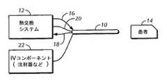
最初に図1を参照すると、血管内温度管理カテーテル10は、患者の中核体温フィードバック信号に応答する治療パラダイムに従ってカテーテル10を通って循環する作用流体の温度を制御するために本明細書に参照されている特許の1つ以上に記載されている論理を実行するプロセッサを備えるカテーテル体温制御システム12と流体連結している。本発明の原理によれば、カテーテル10は、そのカテーテルを使用して患者14における治療低体温を誘導するために使用され得、限定されないが、生理食塩水などの冷却剤が、身体内に入らないように、冷却剤は閉ループ内で循環する。このような治療は、脳卒中、心不全(蘇生後)、急性心筋梗塞、脊髄損傷、および外傷性脳損傷のために示されてもよい。カテーテル10はまた、例えば、バイパス手術または熱傷処置後、患者を加温するため、および例えば、くも膜下出血または脳内出血を患っている患者における異常高熱に対処するために使用されてもよい。 Referring initially to FIG. 1, an intravascular
示されるように、作用流体は、示されるカテーテル10の近位端に接続される供給ライン16および戻りライン18を介して熱交換システム12とカテーテル10との間を循環できる。カテーテルの遠位領域におけるカテーテルを担持する温度センサから患者体温信号が、電線路20を介して、または所望の場合、無線でシステム12に提供され得る。あるいは、患者体温信号は、患者14の体温を測定する別の食道プローブまたは直腸プローブまたは鼓膜センサまたは膀胱プローブまたは他の体温プローブからシステム12に提供されてもよい。本明細書で使用される場合、カテーテルについての「近位」および「遠位」はシステム12に対してであることが留意されるべきである。 As shown, working fluid can circulate between the
作用流体が循環する内側供給管腔および戻り管腔に加えて、カテーテル10はまた、患者に薬剤を注入するための注射器またはIVバッグなどのIVコンポーネント22、あるいは患者のパラメータをモニタリングするための酸素または圧力モニタなどの機器に接続可能である1つ以上の注入管腔を有してもよい。 In addition to the inner supply and return lumens through which the working fluid circulates, the
カテーテル10は、典型的に、患者14の血管系、より好ましくは鼠径部挿入点を通る下大静脈または首(頸部または鎖骨下部)挿入点を通る上大静脈などの患者14の静脈系に配置されてもよい。 The
次に、図2〜9を参照すると、図1を参照して記載されている例示的なカテーテルの特定の態様および/またはコンポーネントは明確さのために図2〜9において省略されていることは理解され、これらの態様および/またはコンポーネントは依然として、非限定的な実施形態において図2〜9に参照して記載されているカテーテル内に存在してもよい。例えば、図1に参照して記載されているIVコンポーネント、温度センサ、および電線路は図2〜9に示されていないが、これらの図に示される非限定的な実施形態において依然として含まれてもよい。 2-9, certain aspects and / or components of the exemplary catheter described with reference to FIG. 1 are omitted in FIGS. 2-9 for clarity. It will be appreciated that these aspects and / or components may still be present in the catheter described in reference to FIGS. 2-9 in non-limiting embodiments. For example, the IV components, temperature sensors, and electrical lines described with reference to FIG. 1 are not shown in FIGS. 2-9, but are still included in the non-limiting embodiments shown in these figures. Also good.
さらに、本明細書に記載されるカテーテルの遠位熱交換領域は、限定されないが、非限定的な実施形態においてニチノールなどの形状記憶材料から作製されてもよいことが理解される。また、非限定的な実施形態において、本明細書に開示される形状記憶材料は、本発明の原理に従って拡張および縮小できる。しかしながら、本明細書に開示されている熱交換領域は、図2〜6のカテーテルの遠位領域が患者と熱交換するために患者内に柔軟に配置され得るように非限定的な実施形態においてフレキシブルおよび/または柔軟であってもよいことはさらに理解される。例えば、本明細書に記載されているカテーテルは、カテーテルが配置される患者の部分の表面領域に対して一定の角度で患者に柔軟に侵入できる。それにも関らず、他の非限定的な実施形態において、熱交換領域32は所望の場合、剛性であってもよい。 Further, it is understood that the distal heat exchange region of the catheter described herein may be made from a shape memory material such as, but not limited to, nitinol in a non-limiting embodiment. Also, in non-limiting embodiments, the shape memory materials disclosed herein can be expanded and contracted according to the principles of the present invention. However, the heat exchange region disclosed herein is in a non-limiting embodiment so that the distal region of the catheter of FIGS. 2-6 can be flexibly positioned within the patient for heat exchange with the patient. It is further understood that it may be flexible and / or flexible. For example, the catheter described herein can flexibly enter a patient at a fixed angle relative to the surface area of the portion of the patient on which the catheter is placed. Nevertheless, in other non-limiting embodiments, the
ここで特に図2を参照して、本発明の原理に従って軸方向に互いに離間しているコイルを有する、患者内に配置されていな状態の血管内温度管理カテーテルの概略図が示される。このように、カテーテル24は、本発明の原理に従って熱交換システム30と流体連結している作用流体供給管腔26および作用流体戻り管腔28を有する。限定されないが、生理食塩水などの作用流体は、カテーテル24が配置される患者38と熱交換するために管腔26および28を通して循環できる。 With particular reference now to FIG. 2, there is shown a schematic diagram of an intravascular temperature management catheter in an undeployed state within a patient having coils axially spaced from one another in accordance with the principles of the present invention. Thus, the
図2から見られ得るように、管腔26および28の少なくとも1つは軸方向に互いに離間している複数のコイル32により規定され、ここで、少なくとも1つの大きなコイル34は、カテーテルが配置される血管(血管は図2には示していない)の壁に接触するように作用流体で膨張できる。図2はまた、少なくとも1つの小さなコイル36を示し、その小さなコイル36のサイズは大きなコイル34に対してである。小さなコイル36は、患者38に配置され、示した非限定的な実施形態において作用流体で膨張する場合、血管の壁と接触しなくてもよい。 As can be seen from FIG. 2, at least one of the
しかしながら、カテーテル24が、小さなコイル36の少なくとも1つにより互いに離間している複数の大きなコイル34を有し得ることは図2の非限定的な実施形態から理解され得る。したがって、一部の実施形態において、1つの大きなコイル34および1つの小さなコイル36のみであってもよいが、図2は、作用流体がコイル32を通して連続的に流れることができるように複数の大きなコイル34および複数の小さなコイル36を示す。さらに、小さなコイル36は、全ての小さなコイル36が大きなコイル34より依然として小さければ、様々なサイズであってもよいことが図2から理解される。 However, it can be seen from the non-limiting embodiment of FIG. 2 that the
さらに図2を参照して、カテーテル24はまた、非限定的な実施形態においてコイル32と同軸で、コイル32と流体連結していてもよい直線状の管40を有してもよい。図2に示されるように、大きなコイル34および小さなコイル36は作用流体供給経路26内にあるが、直線状の管40は作用流体戻り経路28の少なくとも一部を規定する。しかしながら、他の非限定的な実施形態において、直線状の管が本発明の原理に係る作用流体供給経路の少なくとも一部を規定し得る状態で、大きなコイルおよび小さなコイルが作用流体戻り経路内にあってもよいことは理解される。 Still referring to FIG. 2, the
図3に移って、図2を参照して記載した血管内温度管理カテーテル24の概略図が示され、ここで、カテーテル24は患者38の血管42内に配置される。したがって、カテーテル24は依然として、熱交換システム30と流体連結する供給管腔26および戻り管腔28(および示した非限定的な実施形態における管腔28により規定される直線状の管40)を有する。カテーテル24はまた、複数のコイル32が互いに軸方向に離間するように大きなコイル34および小さなコイル36を有する。 Turning to FIG. 3, a schematic diagram of the intravascular
血管42の壁44に大きなコイル34が接触するように、コイル32が作用流体で膨張し、カテーテル24が血管42内の小さなコイル36を中心にするように配置されることは図3から理解され得る。図3からさらに理解され得るように、小さなコイル36は、血管42内に配置され、作用流体で膨張している状態で、血管42の壁44と接触しなくてもよい。したがって、血液は、血流矢印46により示されるようにコイル32を通して連続的に流れて、患者38と熱交換することができる。コイル32は、それらが、患者38と熱交換する最適なコイル表面積を依然として提供しながら、血管42を通る血液の流れを遮断しないように種々のサイズであってもよいこともまた理解され得る。 It can be seen from FIG. 3 that the
ここで図4を参照すると、本発明の原理に係るカテーテルの別の実施形態が示される。具体的には、図4は、血管の壁に対して拡張可能な少なくとも1つのワイヤを有する、患者に配置されていない状態の血管内温度管理カテーテルの概略図であり、カテーテルは、患者と熱交換するカテーテルの熱交換領域を中心にするように配置される。 Referring now to FIG. 4, another embodiment of a catheter according to the principles of the present invention is shown. Specifically, FIG. 4 is a schematic illustration of an intravascular temperature management catheter in an undeployed state with at least one wire that is expandable against the vessel wall, where the catheter and the Centered on the heat exchange area of the catheter to be exchanged.
このように、図4に示されるように、カテーテル48は、本発明の原理に係る熱交換システム54と流体連結する作用流体供給管腔50および作用流体戻り管腔52を有する。限定されないが、生理食塩水などの作用流体は、カテーテル48が配置される患者56と熱交換するように管腔50および52を通して循環できる。カテーテル48はまた、カテーテル48に沿って長手方向に配置され、カテーテル48と係合する少なくとも1つの拡張可能なワイヤ58を備える。血管(図示せず)内にカテーテル48の熱交換領域60を中心にするように、ワイヤ58が患者56に配置される場合、ワイヤ58が患者56の血管の壁に対して拡張可能であることは理解される。複数のワイヤ58を図4に示し、その複数のワイヤ58は熱交換領域60の同じ長手方向部分に沿って係合することは留意すべきである。 Thus, as shown in FIG. 4, the
本明細書で理解されるように、ワイヤ58は、限定されないが、ニチノールなどの形状記憶物質から作製されてもよい。さらに、ワイヤ58が血管の壁に対して拡張される場合、熱交換領域60は実質的にワイヤ58と同軸であり得ることは理解され、これは以下に記載する図5においてさらに理解され得る。しかしながら、他の非限定的な実施形態において、ワイヤ58の一部が患者の血管の壁に対して拡張できる限り、ワイヤ58は熱交換領域60と実質的に同軸であることを必要としない。 As understood herein, the
このように、図5は、図4を参照して記載される血管内温度管理カテーテル48の概略図を示し、ここで、カテーテル48は患者56の血管62内に配置される。カテーテル48は依然として、熱交換システム54と流体連結する管腔50および52を有する。カテーテル48はまた、カテーテル48に沿ってほぼ長手方向に配置され、カテーテル48と係合し得るワイヤ58を有する。 Thus, FIG. 5 shows a schematic diagram of an intravascular
ワイヤ58の一部は、血管62内に熱交換領域60を中心にするように患者の血管62の壁64に対して拡張することは図5から理解され得る。このように、血液は、血流矢印66により示されるように、熱交換領域60を通過するときに、その熱交換領域60と接触できる。 It can be seen from FIG. 5 that a portion of the
ここで図6を参照すると、図4および5を参照して記載されているものと同様のカテーテルの代替の非限定的な実施形態が示される。図6はまた、カテーテルの熱交換領域を中心にするように、カテーテルが配置される血管の壁に対して拡張可能な少なくとも1つのワイヤを有する血管内温度管理カテーテルを示す。しかしながら、図6に示したカテーテルは、熱交換領域に交互に長手方向に沿った複数のワイヤを備え、1つのワイヤのみが熱交換領域の1つの長手方向部分のみと係合する。 Referring now to FIG. 6, an alternative non-limiting embodiment of a catheter similar to that described with reference to FIGS. 4 and 5 is shown. FIG. 6 also shows an intravascular temperature management catheter having at least one wire that is expandable relative to the wall of the blood vessel in which the catheter is placed, centered on the heat exchange area of the catheter. However, the catheter shown in FIG. 6 comprises a plurality of wires alternately along the longitudinal direction in the heat exchange region, with only one wire engaging only one longitudinal portion of the heat exchange region.
このように、図6に示すように、カテーテル68は、本発明の原理に係る熱交換システム74と流体連結する作用流体供給管腔70および作用流体戻り管腔72を有する。限定されないが、生理食塩水などの作用流体は、カテーテル68が配置される患者76と熱交換するように管腔70および72を通って循環できる。カテーテル68はまた、カテーテル68に沿って長手方向に配置され、カテーテル68と係合する拡張可能なワイヤ78を備える。ワイヤ78が、血管(図示せず)内にカテーテル68の熱交換領域80を中心にするように患者76に配置される場合、ワイヤ78は患者76の血管の壁に対して拡張可能であることは理解される。 Thus, as shown in FIG. 6, the
本明細書中で理解されるように、ワイヤ78は本発明の原理に従って形状記憶物質から作製されてもよい。さらに、ワイヤ78が血管の壁に対して拡張する場合、熱交換領域80はワイヤ78と実質的に同軸であってもよいことは理解され、これは以下に記載するように図7を参照してさらに理解され得る。しかしながら、他の非限定的な実施形態において、ワイヤ78の一部が患者の血管の壁に対して拡張できる限り、ワイヤ78は熱交換領域80と実質的に同軸であることを必要としないことが理解される。 As understood herein, the
図4および5を参照して記載した実施形態と対照的に、ここで、ワイヤ78は、熱交換領域80に長手方向に沿って交互にあり、1つのワイヤのみが熱交換領域80の1つの長手方向部分のみに含まれることは図6から理解され得る。長手方向に交互のワイヤ78はまた、図7を参照して見られることができ、この図7は、患者76の血管に配置されている状態のカテーテル68の概略図である。 In contrast to the embodiment described with reference to FIGS. 4 and 5, here the
したがって、図7に示したカテーテル68は依然として、熱交換システム74と流体連結する管腔70および72を有する。カテーテル68はまた、カテーテル68に沿ってほぼ長手方向に配置され、カテーテル68と係合するワイヤ78を有し、1つのワイヤ78のみが熱交換領域80の特定の長手方向部分に沿って係合する。 Accordingly, the
図5と同様に、ワイヤ78の一部が、患者の血管82の壁84に対して拡張できることは図7から理解され得る。したがって、血液は、患者76と熱交換するために、血流矢印86により示すように、熱交換領域80を通過するときに、その熱交換領域80と接触できる。しかしながら、図5の実施形態と対照的に、図7に示した非限定的な実施形態は、熱交換領域80に長手方向に交互に沿ったワイヤ78を有し、血管82内に熱交換領域80を依然として中心にしながら、1つのワイヤのみが熱交換領域80の一部のみと係合する。 Similar to FIG. 5, it can be seen from FIG. 7 that a portion of the
図8に移り、本発明の原理に係る方法の工程がフローチャートとして示される。ブロック88で開始し、本明細書に開示される少なくとも1つの自己中心的な管腔を有するカテーテルは患者に配置され、それにより患者は加温または冷却され得る。次いで、ブロック90において、カテーテルに流体接続される熱交換システムが、管腔を通る作用流体を循環するように作動され、カテーテルが配置される血管の壁に対して管腔の1つにより規定される少なくとも1つの大きなコイルを接触するように管腔は膨張する。管腔の少なくとも1つにより規定される少なくとも1つの小さなコイルもまた、血管内で中心にされる。したがって、血液は本発明の原理に従ってコイルを流れることができ、熱が管腔と血液との間で移動する。 Turning to FIG. 8, the steps of the method according to the principles of the present invention are shown as a flowchart. Beginning at
図9は、カテーテルの近位部分におけるカテーテルハブ106に配置される作用流体供給ポート102および戻りポート104を有するカテーテル100を示す。ガイドワイヤポートおよび1つ以上の注入ポートを備える、さらなる貫通ポート108が設けられてもよい。ポート102、104、108は、本体110を通して延びるカテーテル本体110内で結合する管腔を有する。貫通ポート108と結合する管腔の場合、結合する管腔は、患者の血流内に薬剤を注入するため、または患者の血流から流体を取り除くためのカテーテルの遠位部分112における出口ポートで終端する。遠位部分112は、血液と、供給ポート102に侵入する作用流体との間の熱を交換するための1つ以上の熱交換素子114を備えてもよく、作用流体は供給管腔および熱交換素子を通って循環し、戻りポート104から出て行く。限定されないが、熱交換素子114は膨張可能なバルーン、交互金属ベローズおよび波形部分などであってもよい。 FIG. 9 shows a
図9に示すように、編組線、例えば鋼線、ポリマー鎖、ニチノールなどから作製された管状メッシュ116が、遠位部分112およびその上の熱交換素子114を囲む。メッシュ116は図9に示した半径方向に拡張する構造の間で動いてもよく、メッシュ116は遠位部分112が配置される血管118の内壁と接し、血管を通って流れる血液が熱交換素子114を通ってメッシュ116内に流れるのを著しく妨げず、メッシュ116は半径方向に折り畳まれる構造であり(図10)、メッシュ116は、患者からのカテーテル100の進入および後退を容易にするように熱交換素子114に対して配置されるか、または熱交換素子114から狭い間隔で離間している。 As shown in FIG. 9, a
この目的を達成するために、メッシュ116の遠位端部120は、示したようにカテーテル100の遠位端にしっかりと固定される。この固定は、限定されないが、溶剤結合、rf封止、超音波溶接などによりなされ得る。所望の場合、マーカーバンド122が、例えば蛍光透視を使用してカテーテルの位置を可視化するためにカテーテルの遠位部に沿って配置されてもよい。 To accomplish this goal, the
一方で、メッシュ116の近位端部124は、オペレータ128の近位で終端する、カテーテル100の本体を囲み得る軸方向に移動可能なシース126にしっかりと固定される。オペレータ128は、遠位部120から離れたメッシュ116の近位部124を引っ張るようにして人により近位に移動され得、図10の半径方向に折り畳まれた構造へメッシュ116を動かす。さらに再び、オペレータ128は、遠位部120の方へメッシュ116の近位部124を押すことで人により遠位に移動されてもよく、図9に示した半径方向に拡張した構造へメッシュ116を動かす。この構造において、メッシュ116を画定する編組線は、血管の壁に対して再び開き、血液が流れ、同時に血管内のカテーテルシステムを中心にする。所望の場合、マーカーバンド130は、例えば蛍光透視を使用してカテーテルの位置を可視化するためにメッシュの近位部124に沿って配置されてもよい。 On the other hand, the
特定の自己中心的な患者体温制御カテーテルを本明細書に詳細に示し、記載したが、本発明に含まれる主題は特許請求の範囲のみにより制限されることは理解される。
While certain self-centered patient temperature control catheters have been shown and described in detail herein, it is understood that the subject matter encompassed by the present invention is limited only by the claims.
Claims (5)
Translated fromJapanese少なくとも1つの管腔が、互いに軸方向に離間している複数のコイルにより規定され、
少なくとも1つの第1のコイルが、カテーテルが配置される血管の壁と接触するように作用流体で膨張する大きなコイルであり、血管内の血液の流れを塞がないように前記コイルを通して血液が流れ、
少なくとも1つの第2のコイルが、前記作用流体で膨張した場合、前記血管の前記壁に接触しない小さなコイルであり、
少なくとも1つの第3のコイルが、前記血管の前記壁に接触するように前記作用流体で膨張する前記第2のコイルよりも大きなコイルであり、
前記第2のコイルは、前記第1のコイルおよび前記第3のコイルの間にある、カテーテル。A working fluid supply lumen and a return lumen through which working fluid circulates to exchange heat with a patient in which the catheter is placed;
At least one lumen is defined by a plurality of coils spaced axially from one another;
At least one first coil is a large coil that is inflated with a working fluid to contact the wall of the blood vessel in which the catheter is placed, and blood flows through the coil so as not to block the blood flow in the blood vessel. ,
At least one second coil is a small coil that does not contact the wall of the blood vessel when inflated with the working fluid;
At least one third coil is largerthan the second coil that expands with the working fluid so as to contact the wall of the blood vessel;
The catheter, wherein the second coil is between the first coil and the third coil.
Applications Claiming Priority (5)
| Application Number | Priority Date | Filing Date | Title |
|---|---|---|---|
| US13/247,122US9314370B2 (en) | 2011-09-28 | 2011-09-28 | Self-centering patient temperature control catheter |
| US13/247,122 | 2011-09-28 | ||
| US13/625,998 | 2012-09-25 | ||
| PCT/US2012/056997WO2013048988A1 (en) | 2011-09-28 | 2012-09-25 | Self-centering patient temperature control catheter |
| US13/625,998US9402764B2 (en) | 2011-09-28 | 2012-09-25 | Self-centering patient temperature control catheter |
Publications (2)
| Publication Number | Publication Date |
|---|---|
| JP2014527900A JP2014527900A (en) | 2014-10-23 |
| JP6033312B2true JP6033312B2 (en) | 2016-11-30 |
Family
ID=47912106
Family Applications (1)
| Application Number | Title | Priority Date | Filing Date |
|---|---|---|---|
| JP2014533634AActiveJP6033312B2 (en) | 2011-09-28 | 2012-09-25 | Self-centered patient temperature control catheter |
Country Status (4)
| Country | Link |
|---|---|
| US (3) | US9314370B2 (en) |
| EP (1) | EP2760356B1 (en) |
| JP (1) | JP6033312B2 (en) |
| WO (1) | WO2013048988A1 (en) |
Families Citing this family (23)
| Publication number | Priority date | Publication date | Assignee | Title |
|---|---|---|---|---|
| US9662243B2 (en)* | 2011-09-30 | 2017-05-30 | Zoll Circulation, Inc. | Heat exchange catheters with bi-directional fluid flow and their methods of manufacture and use |
| ITVR20120122A1 (en)* | 2012-06-08 | 2013-12-09 | Bbs Srl | vitreous |
| US9801756B2 (en) | 2012-09-28 | 2017-10-31 | Zoll Circulation, Inc. | Intravascular heat exchange catheter and system with RFID coupling |
| US9241827B2 (en)* | 2012-09-28 | 2016-01-26 | Zoll Circulation, Inc. | Intravascular heat exchange catheter with multiple spaced apart discrete coolant loops |
| DE102013112650B4 (en) | 2013-11-15 | 2018-03-08 | Acandis Gmbh & Co. Kg | Balloon catheter with a catheter tube and a balloon and balloon catheter for endovascular tempering of blood |
| US9474644B2 (en) | 2014-02-07 | 2016-10-25 | Zoll Circulation, Inc. | Heat exchange system for patient temperature control with multiple coolant chambers for multiple heat exchange modalities |
| US10792185B2 (en) | 2014-02-14 | 2020-10-06 | Zoll Circulation, Inc. | Fluid cassette with polymeric membranes and integral inlet and outlet tubes for patient heat exchange system |
| US11033424B2 (en) | 2014-02-14 | 2021-06-15 | Zoll Circulation, Inc. | Fluid cassette with tensioned polymeric membranes for patient heat exchange system |
| US10500088B2 (en) | 2014-02-14 | 2019-12-10 | Zoll Circulation, Inc. | Patient heat exchange system with two and only two fluid loops |
| US11359620B2 (en) | 2015-04-01 | 2022-06-14 | Zoll Circulation, Inc. | Heat exchange system for patient temperature control with easy loading high performance peristaltic pump |
| US9784263B2 (en) | 2014-11-06 | 2017-10-10 | Zoll Circulation, Inc. | Heat exchange system for patient temperature control with easy loading high performance peristaltic pump |
| US11213423B2 (en) | 2015-03-31 | 2022-01-04 | Zoll Circulation, Inc. | Proximal mounting of temperature sensor in intravascular temperature management catheter |
| US10537465B2 (en) | 2015-03-31 | 2020-01-21 | Zoll Circulation, Inc. | Cold plate design in heat exchanger for intravascular temperature management catheter and/or heat exchange pad |
| US10022265B2 (en) | 2015-04-01 | 2018-07-17 | Zoll Circulation, Inc. | Working fluid cassette with hinged plenum or enclosure for interfacing heat exchanger with intravascular temperature management catheter |
| US10737076B2 (en) | 2016-12-21 | 2020-08-11 | Integra LifeSciences Switzerland Sárl | Self-offsetting implantable catheter system |
| US11116657B2 (en) | 2017-02-02 | 2021-09-14 | Zoll Circulation, Inc. | Devices, systems and methods for endovascular temperature control |
| US11185440B2 (en) | 2017-02-02 | 2021-11-30 | Zoll Circulation, Inc. | Devices, systems and methods for endovascular temperature control |
| US11337851B2 (en) | 2017-02-02 | 2022-05-24 | Zoll Circulation, Inc. | Devices, systems and methods for endovascular temperature control |
| US11497648B2 (en) | 2017-05-12 | 2022-11-15 | Zoll Circulation, Inc. | Advanced systems and methods for patient body temperature control |
| US11992433B2 (en) | 2017-05-12 | 2024-05-28 | Zoll Circulation, Inc. | Advanced systems and methods for patient body temperature control |
| US11865035B2 (en) | 2019-03-29 | 2024-01-09 | Zoll Circulation, Inc. | Transport battery for use with portable thermal management system |
| EP4294490A4 (en)* | 2021-02-19 | 2025-01-01 | ZOLL Circulation, Inc. | CATHETER AND SYSTEMS FOR DIRECT INJECTION OF A GAS-ENRICHED LIQUID INTO A PATIENT |
| JP7666874B2 (en) | 2021-03-31 | 2025-04-22 | ゾール サーキュレイション インコーポレイテッド | Temperature Control System |
Family Cites Families (175)
| Publication number | Priority date | Publication date | Assignee | Title |
|---|---|---|---|---|
| US1459112A (en) | 1922-02-23 | 1923-06-19 | Charles F Mehl | Invalid bed |
| US1857031A (en) | 1929-08-02 | 1932-05-03 | Schaffer Edward | Combined hoist and conveyer |
| GB659339A (en) | 1948-04-26 | 1951-10-24 | Bengt Rudolf Dahlberg | Improvements in apparatus for lifting, temporarily supporting and transferring persons in a reclining position |
| US2673987A (en) | 1951-10-22 | 1954-04-06 | James L Upshaw | Invalid carrier with rotatable chair |
| US3225191A (en) | 1962-06-01 | 1965-12-21 | Industrial Dynamics Co | Infrared liquid level inspection system |
| US3425419A (en) | 1964-08-08 | 1969-02-04 | Angelo Actis Dato | Method of lowering and raising the temperature of the human body |
| US3369549A (en) | 1965-10-05 | 1968-02-20 | Thomas A. Armao | Capsule probe having thermoelectric heat exchange means therein |
| US3504674A (en) | 1966-12-22 | 1970-04-07 | Emil S Swenson | Method and apparatus for performing hypothermia |
| GB1183185A (en) | 1967-03-06 | 1970-03-04 | Sp K B Poluprovodnikovykh Prib | Apparatus for Controlling the Temperature of a Living Body |
| US3744555A (en) | 1971-11-12 | 1973-07-10 | Gen Electric | Automatic control of liquid cooling garment by cutaneous and external auditory meatus temperatures |
| US3726269A (en) | 1971-11-24 | 1973-04-10 | W Webster | Cardiovascular catheter for thermal dilution measurement |
| US3751077A (en) | 1972-02-28 | 1973-08-07 | Imp Eastman Corp | Welded sleeve fitting |
| NL7414546A (en) | 1973-11-15 | 1975-05-20 | Rhone Poulenc Sa | SMOOTH HEATING TUBE AND PROCESS FOR MANUFACTURING IT. |
| JPS5247636B2 (en) | 1973-12-15 | 1977-12-03 | ||
| US3937224A (en) | 1974-04-11 | 1976-02-10 | Uecker Ronald L | Colostomy catheter |
| US4126132A (en) | 1975-07-28 | 1978-11-21 | Andros Incorporated | Intravenous and intra arterial delivery system |
| US4065264A (en) | 1976-05-10 | 1977-12-27 | Shiley Laboratories, Inc. | Blood oxygenator with integral heat exchanger for regulating the temperature of blood in an extracorporeal circuit |
| US4103511A (en) | 1976-10-04 | 1978-08-01 | Firma Kress Elektrik Gmbh & Co. | Connecting arrangement for a machine tool |
| US4173228A (en) | 1977-05-16 | 1979-11-06 | Applied Medical Devices | Catheter locating device |
| US4181132A (en) | 1977-05-31 | 1980-01-01 | Parks Leon C | Method and apparatus for effecting hyperthermic treatment |
| US4153048A (en) | 1977-09-14 | 1979-05-08 | Cleveland Clinic Foundation | Thermodilution catheter and method |
| US4259961A (en) | 1979-01-24 | 1981-04-07 | Hood Iii Andrew G | Cooling pad |
| US4298006A (en) | 1980-04-30 | 1981-11-03 | Research Against Cancer, Inc. | Systemic hyperthermia with improved temperature sensing apparatus and method |
| US4532414A (en) | 1980-05-12 | 1985-07-30 | Data Chem., Inc. | Controlled temperature blood warming apparatus |
| US4459468A (en) | 1982-04-14 | 1984-07-10 | Bailey David F | Temperature control fluid circulating system |
| US5370675A (en) | 1992-08-12 | 1994-12-06 | Vidamed, Inc. | Medical probe device and method |
| US4581017B1 (en) | 1983-03-07 | 1994-05-17 | Bard Inc C R | Catheter systems |
| US4554793A (en) | 1983-06-09 | 1985-11-26 | General Eastern Instruments Corporation | Controlled power converter for thermoelectric heat pump drive |
| JPS6028085A (en) | 1983-07-25 | 1985-02-13 | Canon Inc | Head drive device in recording or playback equipment |
| US4672962A (en) | 1983-09-28 | 1987-06-16 | Cordis Corporation | Plaque softening method |
| US4653987A (en) | 1984-07-06 | 1987-03-31 | Tsuyoshi Tsuji | Finger peristaltic infusion pump |
| US4638436A (en) | 1984-09-24 | 1987-01-20 | Labthermics Technologies, Inc. | Temperature control and analysis system for hyperthermia treatment |
| US4661094A (en) | 1985-05-03 | 1987-04-28 | Advanced Cardiovascular Systems | Perfusion catheter and method |
| SE8504501D0 (en) | 1985-09-30 | 1985-09-30 | Astra Meditec Ab | METHOD OF FORMING AN IMPROVED HYDROPHILIC COATING ON A POLYMER SURFACE |
| CH668192A5 (en) | 1985-11-29 | 1988-12-15 | Schneider Medintag Ag | CATHETER FOR TREATING NARROW BODIES, FOR EXAMPLE IN A BLOOD VESSEL. |
| US4665391A (en) | 1986-02-27 | 1987-05-12 | Warner-Lambert Company | Empty container detector |
| US4754752A (en) | 1986-07-28 | 1988-07-05 | Robert Ginsburg | Vascular catheter |
| US4763654A (en) | 1986-09-10 | 1988-08-16 | Jang G David | Tandem independently inflatable/deflatable multiple diameter balloon angioplasty catheter systems and method of use |
| JPS63159300A (en) | 1986-12-23 | 1988-07-02 | Shin Etsu Chem Co Ltd | Method for producing silicon carbide whiskers |
| US4813855A (en) | 1987-06-26 | 1989-03-21 | Tek-Aids Inc. | Peristaltic pump |
| JPS6446056U (en) | 1987-09-17 | 1989-03-22 | ||
| US4860744A (en) | 1987-11-02 | 1989-08-29 | Raj K. Anand | Thermoelectrically controlled heat medical catheter |
| GB2212262B (en) | 1987-11-09 | 1992-07-22 | Solinst Canada Ltd | Liquid level detector |
| US4852567A (en) | 1988-01-21 | 1989-08-01 | C. R. Bard, Inc. | Laser tipped catheter |
| US4941475A (en) | 1988-08-30 | 1990-07-17 | Spectramed, Inc. | Thermodilution by heat exchange |
| JPH03502732A (en) | 1988-10-20 | 1991-06-20 | コナックス バッファロウ コーポレーション | optical level sensor |
| FR2693116B1 (en) | 1992-07-06 | 1995-04-28 | Technomed Int Sa | Urethral probe and apparatus for the therapeutic treatment of prostate tissue by thermotherapy. |
| US5174285A (en) | 1990-01-08 | 1992-12-29 | Lake Shore Medical Development Partners Ltd. | Localized heat transfer device |
| US5342301A (en) | 1992-08-13 | 1994-08-30 | Advanced Polymers Incorporated | Multi-lumen balloons and catheters made therewith |
| US5624392A (en) | 1990-05-11 | 1997-04-29 | Saab; Mark A. | Heat transfer catheters and methods of making and using same |
| US5092841A (en) | 1990-05-17 | 1992-03-03 | Wayne State University | Method for treating an arterial wall injured during angioplasty |
| US5507792A (en) | 1990-09-05 | 1996-04-16 | Breg, Inc. | Therapeutic treatment device having a heat transfer element and a pump for circulating a treatment fluid therethrough |
| US5584804A (en) | 1990-10-10 | 1996-12-17 | Life Resuscitation Technologies, Inc. | Brain resuscitation and organ preservation device and method for performing the same |
| US5195965A (en) | 1991-03-07 | 1993-03-23 | Shantha Totada R | Method and apparatus for localized treatment of human viral infections and cancers |
| JP3091253B2 (en) | 1991-04-25 | 2000-09-25 | オリンパス光学工業株式会社 | Thermal treatment equipment |
| US5192274A (en) | 1991-05-08 | 1993-03-09 | Bierman Steven F | Anchor pad for catheterization system |
| US5542928A (en) | 1991-05-17 | 1996-08-06 | Innerdyne, Inc. | Method and device for thermal ablation having improved heat transfer |
| US5211631A (en) | 1991-07-24 | 1993-05-18 | Sheaff Charles M | Patient warming apparatus |
| GB9118670D0 (en) | 1991-08-30 | 1991-10-16 | Mcnicholas Thomas A | Surgical devices and uses thereof |
| US5304214A (en) | 1992-01-21 | 1994-04-19 | Med Institute, Inc. | Transurethral ablation catheter |
| US6059825A (en) | 1992-03-05 | 2000-05-09 | Angiodynamics, Inc. | Clot filter |
| US5281215A (en) | 1992-04-16 | 1994-01-25 | Implemed, Inc. | Cryogenic catheter |
| US5269758A (en) | 1992-04-29 | 1993-12-14 | Taheri Syde A | Intravascular catheter and method for treatment of hypothermia |
| DE4221390C1 (en) | 1992-06-30 | 1993-04-01 | Haindl, Hans, Dr.Med., 3015 Wennigsen, De | |
| KR940010455B1 (en) | 1992-09-24 | 1994-10-22 | 김영길 | Copper alloy and making method thereof |
| US5403281A (en) | 1992-09-25 | 1995-04-04 | Minnesota Mining And Manufacturing Company | Inline heat exchanger and cardioplegia system |
| US6325067B1 (en) | 1992-12-03 | 2001-12-04 | Wesley D. Sterman | Methods and systems for performing thoracoscopic coronary bypass and other procedures |
| US5437673A (en) | 1993-02-04 | 1995-08-01 | Cryomedical Sciences, Inc. | Closed circulation tissue warming apparatus and method of using the same in prostate surgery |
| US6620188B1 (en) | 1998-08-24 | 2003-09-16 | Radiant Medical, Inc. | Methods and apparatus for regional and whole body temperature modification |
| US5486208A (en) | 1993-02-10 | 1996-01-23 | Ginsburg; Robert | Method and apparatus for controlling a patient's body temperature by in situ blood temperature modification |
| US5837003A (en) | 1993-02-10 | 1998-11-17 | Radiant Medical, Inc. | Method and apparatus for controlling a patient's body temperature by in situ blood temperature modification |
| US5383856A (en) | 1993-03-19 | 1995-01-24 | Bersin; Robert M. | Helical spiral balloon catheter |
| US5626618A (en) | 1993-09-24 | 1997-05-06 | The Ohio State University | Mechanical adjunct to cardiopulmonary resuscitation (CPR), and an electrical adjunct to defibrillation countershock, cardiac pacing, and cardiac monitoring |
| US6716216B1 (en) | 1998-08-14 | 2004-04-06 | Kyphon Inc. | Systems and methods for treating vertebral bodies |
| JP3442863B2 (en) | 1994-06-10 | 2003-09-02 | 隆 松浦 | Patient bed with release frame and moving device for release frame |
| US5716386A (en) | 1994-06-27 | 1998-02-10 | The Ohio State University | Non-invasive aortic impingement and core and cerebral temperature manipulation |
| US5458639A (en) | 1994-08-05 | 1995-10-17 | Medtronic, Inc. | Catheter balloon distal bond |
| EP0698940B1 (en) | 1994-08-24 | 2000-06-14 | Sumitomo Wiring Systems, Ltd. | Wiring circuit for an electrical connection box, method and apparatus for forming the wiring circuit |
| US5486207A (en) | 1994-09-20 | 1996-01-23 | Mahawili; Imad | Thermal pad for portable body heating/cooling system and method of use |
| US5895418A (en) | 1994-09-30 | 1999-04-20 | Saringer Research Inc. | Device for producing cold therapy |
| US5531714A (en) | 1994-11-01 | 1996-07-02 | M. Patricia Lange | Self-guiding, multifunctional visceral catheter |
| US5634907A (en) | 1994-12-22 | 1997-06-03 | Sandoz Nutrition Ltd. | System for detection of fluid infusion |
| US5980561A (en) | 1995-03-01 | 1999-11-09 | Kolen; Paul T. | Applying thermal therapy to living tissue |
| DE19531935A1 (en) | 1995-08-17 | 1997-02-20 | Panagiotis Tsolkas | Device for whole body hyperthermia treatment |
| US5730720A (en) | 1995-08-18 | 1998-03-24 | Ip Scientific, Inc. | Perfusion hyperthermia treatment system and method |
| US5701905A (en) | 1995-11-13 | 1997-12-30 | Localmed, Inc. | Guide catheter with sensing element |
| DE29602173U1 (en) | 1996-02-08 | 1997-06-26 | B. Braun Melsungen Ag, 34212 Melsungen | Application device for medical liquids |
| US5733319A (en) | 1996-04-25 | 1998-03-31 | Urologix, Inc. | Liquid coolant supply system |
| US5676670A (en) | 1996-06-14 | 1997-10-14 | Beth Israel Deaconess Medical Center | Catheter apparatus and method for creating a vascular bypass in-vivo |
| US5776079A (en) | 1996-08-06 | 1998-07-07 | Cook Incorporated | Retrograde-antegrade catheterization guide wire |
| US6146141A (en) | 1996-10-02 | 2000-11-14 | Schumann; Edgar | Laser pistol |
| US6124452A (en) | 1997-12-19 | 2000-09-26 | University Of Nebraska-Lincoln | Octafluoro-meso-tetraarylporphyrins and methods for making these compounds |
| US5849016A (en) | 1996-12-03 | 1998-12-15 | Suhr; William S. | Catheter exchange method and apparatus |
| US5788647A (en) | 1997-01-24 | 1998-08-04 | Eggers; Philip E. | Method, system and apparatus for evaluating hemodynamic parameters |
| US6110097A (en) | 1997-03-06 | 2000-08-29 | Scimed Life Systems, Inc. | Perfusion balloon catheter with radioactive source |
| WO1998040017A2 (en) | 1997-03-12 | 1998-09-17 | Advanced Closure Systems, Inc. | Vascular sealing device |
| US7027869B2 (en) | 1998-01-07 | 2006-04-11 | Asthmatx, Inc. | Method for treating an asthma attack |
| JPH10305103A (en) | 1997-05-08 | 1998-11-17 | Nippon Sherwood Medical Ind Ltd | Catheter fixture |
| US5862675A (en) | 1997-05-30 | 1999-01-26 | Mainstream Engineering Corporation | Electrically-driven cooling/heating system utilizing circulated liquid |
| US5908407A (en) | 1997-07-25 | 1999-06-01 | Neuroperfusion, Inc. | Retroperfusion catheter apparatus and method |
| US6283940B1 (en) | 1997-08-29 | 2001-09-04 | S. Grant Mulholland | Catheter |
| US6110139A (en) | 1997-10-21 | 2000-08-29 | Loubser; Paul Gerhard | Retrograde perfusion monitoring and control system |
| AU1712599A (en) | 1997-12-08 | 1999-06-28 | Cardeon Corporation | Aortic catheter and methods for inducing cardioplegic arrest and for selective aortic perfusion |
| US6843800B1 (en) | 1998-01-23 | 2005-01-18 | Innercool Therapies, Inc. | Patient temperature regulation method and apparatus |
| US6096068A (en) | 1998-01-23 | 2000-08-01 | Innercool Therapies, Inc. | Selective organ cooling catheter and method of using the same |
| US7371254B2 (en)* | 1998-01-23 | 2008-05-13 | Innercool Therapies, Inc. | Medical procedure |
| US6231595B1 (en) | 1998-03-31 | 2001-05-15 | Innercool Therapies, Inc. | Circulating fluid hypothermia method and apparatus |
| US6719779B2 (en) | 2000-11-07 | 2004-04-13 | Innercool Therapies, Inc. | Circulation set for temperature-controlled catheter and method of using the same |
| US6558412B2 (en)* | 1998-01-23 | 2003-05-06 | Innercool Therapies, Inc. | Selective organ hypothermia method and apparatus |
| US6051019A (en) | 1998-01-23 | 2000-04-18 | Del Mar Medical Technologies, Inc. | Selective organ hypothermia method and apparatus |
| US6254626B1 (en)* | 1998-03-24 | 2001-07-03 | Innercool Therapies, Inc. | Articulation device for selective organ cooling apparatus |
| US6261312B1 (en) | 1998-06-23 | 2001-07-17 | Innercool Therapies, Inc. | Inflatable catheter for selective organ heating and cooling and method of using the same |
| US6464716B1 (en) | 1998-01-23 | 2002-10-15 | Innercool Therapies, Inc. | Selective organ cooling apparatus and method |
| US6042559A (en) | 1998-02-24 | 2000-03-28 | Innercool Therapies, Inc. | Insulated catheter for selective organ perfusion |
| US6599312B2 (en) | 1998-03-24 | 2003-07-29 | Innercool Therapies, Inc. | Isolated selective organ cooling apparatus |
| US6520933B1 (en) | 1998-04-21 | 2003-02-18 | Alsius Corporation | Central venous line cooling catheter having a spiral-shaped heat exchange member |
| US6149670A (en) | 1999-03-11 | 2000-11-21 | Alsius Corporation | Method and system for treating cardiac arrest using hypothermia |
| US6589271B1 (en) | 1998-04-21 | 2003-07-08 | Alsius Corporations | Indwelling heat exchange catheter |
| US6126684A (en) | 1998-04-21 | 2000-10-03 | The Regents Of The University Of California | Indwelling heat exchange catheter and method of using same |
| US6645234B2 (en)* | 1998-04-21 | 2003-11-11 | Alsius Corporation | Cardiovascular guiding catheter with heat exchange properties and methods of use |
| US6530946B1 (en) | 1998-04-21 | 2003-03-11 | Alsius Corporation | Indwelling heat exchange heat pipe catheter and method of using same |
| US7255709B2 (en) | 1998-04-21 | 2007-08-14 | Alsius Corporation | Intravascular heat exchange catheter with temperature sensor |
| US6338727B1 (en) | 1998-08-13 | 2002-01-15 | Alsius Corporation | Indwelling heat exchange catheter and method of using same |
| US6450990B1 (en) | 1998-08-13 | 2002-09-17 | Alsius Corporation | Catheter with multiple heating/cooling fibers employing fiber spreading features |
| US6312461B1 (en) | 1998-08-21 | 2001-11-06 | John D. Unsworth | Shape memory tubular stent |
| US6428563B1 (en) | 2000-01-21 | 2002-08-06 | Radiant Medical, Inc. | Heat exchange catheter with improved insulated region |
| US6610083B2 (en) | 1998-08-24 | 2003-08-26 | Radiant Medical, Inc. | Multiple lumen heat exchange catheters |
| US6146411A (en) | 1998-12-24 | 2000-11-14 | Alsius Corporation | Cooling system for indwelling heat exchange catheter |
| DE60023118T2 (en) | 1999-01-04 | 2006-07-13 | Medivance, Inc., Louisville | IMPROVED COOLING / HEATING CUSHION AND SYSTEM |
| US6299599B1 (en) | 1999-02-19 | 2001-10-09 | Alsius Corporation | Dual balloon central venous line catheter temperature control system |
| US6019783A (en) | 1999-03-02 | 2000-02-01 | Alsius Corporation | Cooling system for therapeutic catheter |
| US6702811B2 (en) | 1999-04-05 | 2004-03-09 | Medtronic, Inc. | Ablation catheter assembly with radially decreasing helix and method of use |
| US6148634A (en) | 1999-04-26 | 2000-11-21 | 3M Innovative Properties Company | Multistage rapid product refrigeration apparatus and method |
| US6436071B1 (en) | 1999-06-08 | 2002-08-20 | The Trustees Of Columbia University In The City Of New York | Intravascular systems for corporeal cooling |
| US20030236496A1 (en) | 1999-08-03 | 2003-12-25 | Samson Wilfred J. | Aortic catheter with porous aortic arch balloon and methods for selective aortic perfusion |
| US6231594B1 (en) | 1999-08-11 | 2001-05-15 | Radiant Medical, Inc. | Method of controlling body temperature while reducing shivering |
| US6264679B1 (en) | 1999-08-20 | 2001-07-24 | Radiant Medical, Inc. | Heat exchange catheter with discrete heat exchange elements |
| US20040089058A1 (en) | 1999-09-09 | 2004-05-13 | De Haan Peter Hillebrand | Sensor for detecting the presence of moisture |
| US6554791B1 (en) | 1999-09-29 | 2003-04-29 | Smisson-Cartledge Biomedical, Llc | Rapid infusion system |
| WO2001041708A2 (en) | 1999-12-07 | 2001-06-14 | Alsius Corporation | Method and system for treating stroke using hypothermia |
| WO2001043661A2 (en) | 1999-12-14 | 2001-06-21 | Radiant Medical, Inc. | Method for reducing myocardial infarct by applicaton of intravascular hypothermia |
| US6383144B1 (en) | 2000-01-18 | 2002-05-07 | Edwards Lifesciences Corporation | Devices and methods for measuring temperature of a patient |
| US6624679B2 (en) | 2000-01-31 | 2003-09-23 | Stmicroelectronics S.R.L. | Stabilized delay circuit |
| AU2001238434B2 (en) | 2000-02-28 | 2006-01-19 | Radiant Medical, Inc. | Disposable cassette for intravascular heat exchange catheter |
| US6485500B1 (en) | 2000-03-21 | 2002-11-26 | Advanced Cardiovascular Systems, Inc. | Emboli protection system |
| US6849072B2 (en) | 2000-04-07 | 2005-02-01 | The General Hospital Corporation | Methods and apparatus for thermally affecting tissue |
| WO2001083001A1 (en) | 2000-05-02 | 2001-11-08 | Vasca, Inc. | Methods and devices for draining fluids in and out of the body |
| US6551309B1 (en) | 2000-09-14 | 2003-04-22 | Cryoflex, Inc. | Dual action cryoprobe and methods of using the same |
| US6719723B2 (en) | 2000-12-06 | 2004-04-13 | Innercool Therapies, Inc. | Multipurpose catheter assembly |
| WO2002047577A2 (en) | 2000-12-15 | 2002-06-20 | Alsius Corporation | Radio frequency patient heating system |
| US6544282B1 (en) | 2001-02-21 | 2003-04-08 | Radiant Medical, Inc. | Inhibition of platelet activation, aggregation and/or adhesion by hypothermia |
| WO2002078513A2 (en) | 2001-03-30 | 2002-10-10 | Augmentech, Inc. | Patient incontinence/position monitoring apparatus and method of use thereof |
| US6699269B2 (en) | 2001-04-30 | 2004-03-02 | Rohit K. Khanna | Selective brain and spinal cord hypothermia method and apparatus |
| US7057273B2 (en) | 2001-05-15 | 2006-06-06 | Gem Services, Inc. | Surface mount package |
| US6752786B2 (en) | 2001-05-31 | 2004-06-22 | Radiant Medical, Inc. | Moving heat exchange catheter system |
| US6706060B2 (en) | 2001-06-05 | 2004-03-16 | Alsius Corporation | Heat exchange catheter |
| US6679906B2 (en) | 2001-07-13 | 2004-01-20 | Radiant Medical, Inc. | Catheter system with on-board temperature probe |
| GB0125294D0 (en) | 2001-10-22 | 2001-12-12 | Bickford Smith Philip | Medical small-bore tubing connectors |
| US20030153845A1 (en) | 2002-02-11 | 2003-08-14 | Jeremy Emken | Centering brachytherapy catheter |
| US6685733B1 (en) | 2002-04-10 | 2004-02-03 | Radiant Medical, Inc. | Methods and systems for reducing substance-induced renal damage |
| US6969399B2 (en) | 2002-07-11 | 2005-11-29 | Life Recovery Systems Hd, Llc | Apparatus for altering the body temperature of a patient |
| CA2497181C (en) | 2002-09-12 | 2013-08-13 | Radiant Medical, Inc. | System and method for determining and controlling core body temperature |
| US6887263B2 (en) | 2002-10-18 | 2005-05-03 | Radiant Medical, Inc. | Valved connector assembly and sterility barriers for heat exchange catheters and other closed loop catheters |
| US6799342B1 (en) | 2003-05-27 | 2004-10-05 | Robert G. Jarmon | Method and apparatus for supporting a body |
| US20050156744A1 (en) | 2003-09-02 | 2005-07-21 | Pires Harold G. | Diaper wetness annunciator system |
| FR2863162B1 (en) | 2003-12-05 | 2006-12-08 | Vygon | MALE FITTINGS AND FEMALE FITTINGS FOR REALIZING LIQUID TRANSMISSION CONNECTIONS, IN PARTICULAR FOR ENTERALE NUTRITION LINES |
| US20060004417A1 (en) | 2004-06-30 | 2006-01-05 | Cvrx, Inc. | Baroreflex activation for arrhythmia treatment |
| US7708715B2 (en) | 2005-03-21 | 2010-05-04 | Boston Scientific Scimed, Inc. | Tissue approximation device |
| US7822485B2 (en) | 2006-09-25 | 2010-10-26 | Zoll Circulation, Inc. | Method and apparatus for spinal cooling |
| US20090264988A1 (en)* | 2008-04-18 | 2009-10-22 | Medtronic Vascular, Inc. | Stent Graft Delivery System Including Support for Fenestration in Situ and a Mechanism for Modeling |
| US8162879B2 (en) | 2008-09-22 | 2012-04-24 | Tyco Healthcare Group Lp | Double balloon catheter and methods for homogeneous drug delivery using the same |
| US9579150B2 (en) | 2011-04-08 | 2017-02-28 | Covidien Lp | Microwave ablation instrument with interchangeable antenna probe |
| US10045881B2 (en) | 2011-09-28 | 2018-08-14 | Zoll Circulation, Inc. | Patient temperature control catheter with helical heat exchange paths |
| US8888832B2 (en) | 2011-09-28 | 2014-11-18 | Zoll Circulation, Inc. | System and method for doubled use of patient temperature control catheter |
| US9662243B2 (en) | 2011-09-30 | 2017-05-30 | Zoll Circulation, Inc. | Heat exchange catheters with bi-directional fluid flow and their methods of manufacture and use |
- 2011
- 2011-09-28USUS13/247,122patent/US9314370B2/enactiveActive
- 2012
- 2012-09-25JPJP2014533634Apatent/JP6033312B2/enactiveActive
- 2012-09-25EPEP12837381.8Apatent/EP2760356B1/enactiveActive
- 2012-09-25USUS13/625,998patent/US9402764B2/enactiveActive
- 2012-09-25WOPCT/US2012/056997patent/WO2013048988A1/enactiveApplication Filing
- 2015
- 2015-03-13USUS14/656,915patent/US20150182377A1/ennot_activeAbandoned
Also Published As
| Publication number | Publication date |
|---|---|
| WO2013048988A1 (en) | 2013-04-04 |
| EP2760356A4 (en) | 2015-05-20 |
| US20150182377A1 (en) | 2015-07-02 |
| JP2014527900A (en) | 2014-10-23 |
| US9402764B2 (en) | 2016-08-02 |
| US20130079859A1 (en) | 2013-03-28 |
| EP2760356B1 (en) | 2016-07-06 |
| US20130079856A1 (en) | 2013-03-28 |
| EP2760356A1 (en) | 2014-08-06 |
| US9314370B2 (en) | 2016-04-19 |
Similar Documents
| Publication | Publication Date | Title |
|---|---|---|
| JP6033312B2 (en) | Self-centered patient temperature control catheter | |
| US12127971B2 (en) | Patient temperature control catheter with helical heat exchange paths | |
| US10596029B2 (en) | Intravascular heat exchange catheter with rib cage-like coolant path | |
| EP3562449B1 (en) | High efficiency heat exchange catheters for control of patient body temperature | |
| US9717625B2 (en) | Intravascular heat exchange catheter with non-round coiled coolant path | |
| US9241827B2 (en) | Intravascular heat exchange catheter with multiple spaced apart discrete coolant loops | |
| JP5763843B2 (en) | Patient temperature control catheter with outer sleeve cooled by inner sleeve | |
| JP6043357B2 (en) | Transatrial patient temperature control catheter | |
| JP5905969B2 (en) | System and method for dual use of a patient temperature control catheter | |
| AU2007242941A1 (en) | Methods and apparatus for regional and whole body temperature modification |
Legal Events
| Date | Code | Title | Description |
|---|---|---|---|
| A621 | Written request for application examination | Free format text:JAPANESE INTERMEDIATE CODE: A621 Effective date:20140804 | |
| A977 | Report on retrieval | Free format text:JAPANESE INTERMEDIATE CODE: A971007 Effective date:20150715 | |
| A131 | Notification of reasons for refusal | Free format text:JAPANESE INTERMEDIATE CODE: A131 Effective date:20150804 | |
| A521 | Request for written amendment filed | Free format text:JAPANESE INTERMEDIATE CODE: A523 Effective date:20151104 | |
| A02 | Decision of refusal | Free format text:JAPANESE INTERMEDIATE CODE: A02 Effective date:20160426 | |
| A521 | Request for written amendment filed | Free format text:JAPANESE INTERMEDIATE CODE: A523 Effective date:20160823 | |
| A911 | Transfer to examiner for re-examination before appeal (zenchi) | Free format text:JAPANESE INTERMEDIATE CODE: A911 Effective date:20160831 | |
| TRDD | Decision of grant or rejection written | ||
| A01 | Written decision to grant a patent or to grant a registration (utility model) | Free format text:JAPANESE INTERMEDIATE CODE: A01 Effective date:20161004 | |
| A61 | First payment of annual fees (during grant procedure) | Free format text:JAPANESE INTERMEDIATE CODE: A61 Effective date:20161025 | |
| R150 | Certificate of patent or registration of utility model | Ref document number:6033312 Country of ref document:JP Free format text:JAPANESE INTERMEDIATE CODE: R150 | |
| R250 | Receipt of annual fees | Free format text:JAPANESE INTERMEDIATE CODE: R250 | |
| R250 | Receipt of annual fees | Free format text:JAPANESE INTERMEDIATE CODE: R250 | |
| R250 | Receipt of annual fees | Free format text:JAPANESE INTERMEDIATE CODE: R250 | |
| R250 | Receipt of annual fees | Free format text:JAPANESE INTERMEDIATE CODE: R250 | |
| R250 | Receipt of annual fees | Free format text:JAPANESE INTERMEDIATE CODE: R250 | |
| R250 | Receipt of annual fees | Free format text:JAPANESE INTERMEDIATE CODE: R250 |