JP6032486B2 - Power management system and power management method - Google Patents
Power management system and power management methodDownload PDFInfo
- Publication number
- JP6032486B2 JP6032486B2JP2013052494AJP2013052494AJP6032486B2JP 6032486 B2JP6032486 B2JP 6032486B2JP 2013052494 AJP2013052494 AJP 2013052494AJP 2013052494 AJP2013052494 AJP 2013052494AJP 6032486 B2JP6032486 B2JP 6032486B2
- Authority
- JP
- Japan
- Prior art keywords
- storage battery
- power
- frequency
- compensation
- load
- Prior art date
- Legal status (The legal status is an assumption and is not a legal conclusion. Google has not performed a legal analysis and makes no representation as to the accuracy of the status listed.)
- Active
Links
Images


Landscapes
- Supply And Distribution Of Alternating Current (AREA)
Description
Translated fromJapanese本発明は、ピーク電力削減量を最大化する電力管理システム、電力管理方法に関する。 The present invention relates to a power management system and a power management method for maximizing a peak power reduction amount.
近年、電力需要が伸びる重負荷期の夏期、及び冬期の電力逼迫により、需要家側には、積極的なピーク電力削減が求められている。また、分散型電源に対する固定買取制度の開始や、環境負荷低減などの観点から太陽光発電の導入機運が高まっている。分散型電源を有するシステムとしては、例えば下記の特許文献1に記載されたシステムがある。このような背景から、電力ピーク時間帯に太陽光発電を用いてピーク電力を削減することが期待されている。しかしながら、太陽光発電等の自然エネルギーは、天候次第で大きく出力が変動するため、確実にピーク電力を削減できるとは限らない。 In recent years, due to the tightening of power during the heavy load season in summer and winter when the demand for power is increasing, the customers have been required to actively reduce peak power. In addition, the introduction of photovoltaic power generation is increasing from the perspective of starting a fixed purchase system for distributed power sources and reducing environmental impact. As a system having a distributed power source, for example, there is a system described in
この対策として、太陽光発電と蓄電池とで構成されるマイクログリッドが開発、実用化されている。ここで、図9は、マイクログリッドの蓄電池の負荷変動補償の一例を示す図である。この図において、横軸は時刻、縦軸は建物の消費電力を表している。このマイクログリッドの蓄電池は、建物の負荷変動に蓄電池出力を追従させることで、電力会社からの買電電力の変動を抑制する(以下、負荷変動補償と呼ぶ)制御を行っている。ここで、符号aは、負荷変動補償前の負荷電力(建物内における負荷電力)を表しており、符号bは、負荷変動補償後の買電電力(負荷変動補償を行った場合に消費される買電電力)を表している。この図においては、10時から16時までの間において、蓄電池からの電力も必要に応じて建物に供給することで、負荷の急増時や、太陽光発電の出力減少時には、蓄電池から放電が行われ、ピーク電力を削減することができる。例えば、符号aにおけるピーク値と符号bにおけるピーク値との差(ピーク電力削減量)に示すように、ピーク電力を削減することができる。 As a countermeasure, a microgrid composed of photovoltaic power generation and a storage battery has been developed and put into practical use. Here, FIG. 9 is a diagram illustrating an example of load variation compensation of a microgrid storage battery. In this figure, the horizontal axis represents time and the vertical axis represents power consumption of the building. The microgrid storage battery performs control (hereinafter referred to as load fluctuation compensation) to suppress fluctuations in the purchased power from the power company by causing the output of the storage battery to follow the load fluctuation of the building. Here, symbol a represents load power before load variation compensation (load power in a building), and symbol b is consumed when purchased power after load variation compensation (load variation compensation is performed). Power purchase). In this figure, during the period from 10:00 to 16:00, power from the storage battery is supplied to the building as necessary, so that when the load suddenly increases or the output of the solar power generation decreases, the storage battery discharges. The peak power can be reduced. For example, the peak power can be reduced as indicated by the difference (peak power reduction amount) between the peak value at symbol a and the peak value at symbol b.
ところで、建物の負荷変動は、様々な周波数成分で構成されているため、与えられた蓄電池容量で最大限のピーク電力削減量を得るためには、蓄電池で補償すべき負荷変動の周波数帯域(以下、補償帯域と呼ぶ)を適切に決定することが重要である。上述した従来技術では、シミュレーションや、実運転などを繰り返し行い、ピーク電力削減効果の大きい補償帯域を、試行錯誤的に決定していたため、多大な労力と時間がかかっていた。 By the way, since the load fluctuation of the building is composed of various frequency components, in order to obtain the maximum peak power reduction amount with a given storage battery capacity, the frequency band of the load fluctuation to be compensated by the storage battery (hereinafter referred to as the frequency fluctuation) It is important to appropriately determine the compensation band. In the above-described conventional technology, simulation and actual operation are repeatedly performed, and a compensation band having a large peak power reduction effect is determined by trial and error, which requires a lot of labor and time.
そのため、日々異なる気象条件等で負荷電力パターンが変化した場合における補償帯域の再設定が困難であり、同じ補償帯域を使用し続けていた。また、あらかじめ補償帯域を広く設定すると、実効蓄電池容量を上回り、運用途中で蓄電池容量が枯渇する場合があった。これらの理由により、毎日の運用において実効蓄電池容量で最大限のピーク電力削減量を得られていないという問題がある。 Therefore, it is difficult to reset the compensation band when the load power pattern changes due to different weather conditions every day, and the same compensation band has been used continuously. In addition, if the compensation band is set wide in advance, the effective storage battery capacity may be exceeded, and the storage battery capacity may be exhausted during operation. For these reasons, there is a problem that the maximum peak power reduction amount cannot be obtained with the effective storage battery capacity in daily operation.
本発明は、このような事情を考慮してなされたものであり、その目的は、与えられた蓄電池容量に対してピーク電力削減量が最大となる補償帯域を、高速、かつ最適に決定することができる電力管理システム、電力管理方法を提供することにある。 The present invention has been made in view of such circumstances, and its purpose is to determine a compensation band at which the peak power reduction amount is maximum for a given storage battery capacity at high speed and optimally. It is to provide a power management system and a power management method.
上述した課題を解決するために、本発明は、発電装置が発電した発電電力と商用の電力系統から供給される買電電力とに基づいて蓄電池の出力を制御する電力管理システムであって、制御対象日の気象情報と類似した気象情報に対応付けられて記録されている負荷電力の過去実績データを取得する負荷電力取得部と、前記負荷電力取得部によって取得した過去実績データに基づいて、前記蓄電池の補償周波数帯域を決定する補償帯域決定部と、前記補償帯域決定部によって決定された前記蓄電池の補償周波数帯域と、前記買電電力、及び前記蓄電池の出力の合計とに基づいて負荷電力を推定し、該推定した負荷電力に基づいて前記蓄電池の出力を制御する蓄電池制御部とを備え、前記補償帯域決定部は、前記負荷電力の過去実績データから離散フーリエ変換によって各周波数の振幅を算出し、該振幅と周波数とに基づいて、低域遮断周波数と負荷変動補償に必要な蓄電池容量との関係を求め、2点の線形補間により、実効蓄電池容量で最も補償帯域を広くとれる低域遮断周波数を決定することを特徴とする。In order to solve the above-described problems, the present invention is a power management system that controls the output of a storage battery based on generated power generated by a power generation device and purchased power supplied from a commercial power system. Based on the past power data acquired by the load power acquisition unit, the load power acquisition unit that acquires the past power data of the load power recorded in association with the weather information similar to the weather information of the target day, A compensation band determining unit that determines a compensation frequency band of the storage battery, a compensation frequency band of the storage battery determined by the compensation band determination unit, the purchased power, and a load power based on a total of the output of the storage battery estimated, and a battery control unit for controlling the output of the storage battery based on the load electric power theestimated, the compensation range determining unit away from the past record data of the load power The amplitude of each frequency is calculated by Fourier transform, and the relationship between the low-frequency cutoff frequency and the storage battery capacity necessary for load fluctuation compensation is obtained based on the amplitude and frequency, and the effective storage battery capacity is calculated by two-point linear interpolation. It characterized thatyou determine broadly take low cut-off frequency of the most compensation range.
本発明は、上記の発明において、前記負荷電力取得部は、気象情報とその気象情報を有する日の負荷電力データとを対応付けて蓄積する過去実績データ蓄積部と、制御対象日の気象情報を取得する気象情報取得部と、前記気象情報取得部によって取得した制御対象日の気象情報と類似した気象情報に対応付けられて記録されている負荷電力データを、前記過去実績データ蓄積部から取得する気象類似日負荷電力データ取得部とを備えることを特徴とする。 According to the present invention, in the above invention, the load power acquisition unit stores the past performance data storage unit that stores the weather information and the load power data of the day having the weather information in association with each other, and the weather information of the control target day. Acquires the load power data recorded in association with the weather information similar to the weather information similar to the weather information acquired by the weather information acquisition unit and the weather information acquisition unit acquired from the past performance data storage unit. And a weather-like daily load power data acquisition unit.
本発明は、上記の発明において、前記蓄電池制御部は、前記補償帯域決定部によって決定された前記蓄電池の補償周波数帯域に基づいて、前記買電電力と前記蓄電池の出力との合計値をフィルタリングすることで、前記蓄電池の出力を制御する蓄電池出力指令値を出力することを特徴とする。 According to the present invention, in the above invention, the storage battery control unit filters a total value of the purchased power and the output of the storage battery based on the compensation frequency band of the storage battery determined by the compensation band determination unit. Thus, a storage battery output command value for controlling the output of the storage battery is output.
また、上述した課題を解決するために、本発明は、発電装置が発電した発電電力と商用の電力系統から供給される買電電力とに基づいて蓄電池の出力を制御する電力管理方法であって、制御対象日の気象情報と類似した気象情報に対応付けられて記録されている負荷電力の過去実績データを取得するステップと、前記取得した過去実績データに基づいて、前記蓄電池の補償周波数帯域を決定するステップと、前記決定された前記蓄電池の補償周波数帯域と、前記買電電力、及び前記蓄電池の出力の合計とに基づいて負荷電力を推定し、該推定した負荷電力に基づいて前記蓄電池の出力を制御するステップとを備え、前記補償周波数帯域を決定するステップは、前記負荷電力の過去実績データから離散フーリエ変換によって各周波数の振幅を算出し、該振幅と周波数とに基づいて、低域遮断周波数と負荷変動補償に必要な蓄電池容量との関係を求め、2点の線形補間により、実効蓄電池容量で最も補償帯域を広くとれる低域遮断周波数を決定することを特徴とする。In order to solve the above-described problem, the present invention is a power management method for controlling the output of a storage battery based on generated power generated by a power generation device and purchased power supplied from a commercial power system. A step of acquiring past performance data of load power recorded in association with weather information similar to the weather information of the control target date, and a compensation frequency band of the storage battery based on the acquired past performance data Determining a load power based on the determined step, the determined compensation frequency band of the storage battery, the purchased power, and the output of the storage battery, and based on the estimated load power of the storage battery and a step of controlling theoutput, determining the compensation frequency band, calculate the amplitude of each frequency by a discrete Fourier transform from the past record data of the load power Based on the amplitude and frequency, the relationship between the low-frequency cutoff frequency and the storage battery capacity required for load fluctuation compensation is obtained, and the low-frequency cutoff that allows the widest compensation band with the effective storage battery capacity is obtained by two-point linear interpolation. and features thatyou determine the frequency.
この発明によれば、与えられた蓄電池容量に対してピーク電力削減量が最大となる補償帯域を、高速、かつ最適に決定することができる。 According to the present invention, the compensation band that maximizes the peak power reduction amount for a given storage battery capacity can be determined at high speed and optimally.
以下、本発明の一実施形態を、図面を参照して説明する。 Hereinafter, an embodiment of the present invention will be described with reference to the drawings.
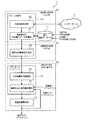
図1は、本実施形態の電力管理システム1の構成を示すブロック図である。本発明は、蓄電池によるピーク電力削減効果を向上させる電力管理システムとして、与えられた蓄電池容量に対してピーク電力削減量が最大となる補償帯域の上下限周波数を、高速、かつ最適に決定する機能(以下、補償帯域決定機能と呼ぶ)を備えている。上下限周波数は、上記補償帯域の上限(高域側)の周波数と下限(低域側)の周波数とを表し、以下、高域・低域遮断周波数と称することもある。 FIG. 1 is a block diagram showing the configuration of the
図1において、電力管理システム1は、システム演算部10と、過去実績データDB(データベース)11と、リアルタイムコントローラ12と、定置用蓄電池部13とからなる。システム演算部10は、気象情報取得部20と気象類似日負荷電力データ取得部21と蓄電池補償帯域決定部22とを有する。リアルタイムコントローラ12は、決定補償帯域格納部30と、蓄電池出力指令値計算部31とを有する。 In FIG. 1, the
また、上記気象情報取得部20と、気象類似日負荷電力データ取得部21と、過去実績データDB11とで負荷電力取得部40として構成することもできる。また、蓄電池補償帯域決定部22は、補償帯域決定部(補償帯域決定機能)41として構成することもできる。また、決定補償帯域格納部30と、蓄電池出力指令値計算部31と、定置用蓄電池部13とで、蓄電池制御部42として構成することもできる。 Moreover, it can also comprise as the load electric
負荷電力取得部40は、制御対象日の前日に翌日(制御対象日)の気象情報と類似した気象情報に対応付けられて記録されている負荷電力の過去実績データ(平日、土日・祝日に対応)を取得する(1日1回)。より具体的には、過去実績データDB11は、外部に設けられたシステムから、負荷電力の履歴と、太陽光発電装置によって発電された電力を表すPV発電電力と、天気、温度、湿度等を含む気象情報とを対応づけて記憶する。気象情報取得部20は、インターネット2を介して天気、温度、湿度等を含む気象情報を外部に接続された気象情報提供サーバ等から取得する。気象類似日負荷電力データ取得部21は、気象情報取得部20によって取得した気象情報に類似する気象情報が対応づけられた負荷電力のデータやPV発電電力のデータを、過去実績データとして過去実績データDB11から取得する。気象情報が類似するか否かの判定は、例えば、天気(天候)が同じであり、お互いの温度と湿度とが、それぞれ所定の範囲内にあれば類似すると判定し、天気が異なったり、天気が同じであっても、お互いの温度と湿度との少なくともいずれかが、所定の範囲外である場合には、類似しないと判定する。 The load
補償帯域決定部41(蓄電池補償帯域決定部22)は、負荷電力取得部40が取得した過去実績データを用いて、高域・低域遮断周波数を決定する。すなわち、蓄電池補償帯域決定部22は、時刻の経過と負荷電力との関係を表す負荷電力プロファイルのうち、ある時刻の範囲における負荷電力プロファイルから、あるいは、過去の類似する電力プロファイルや、シミュレーション結果などを解析することで、その負荷電力プロファイルに対応する最適な蓄電池の補償周波数帯域(低域遮断周波数、及び高域遮断周波数)を求める。高域遮断周波数については、短周期の速い変動を補償してもピーク電力削減効果が小さいことから固定値として、以下の手順で低域遮断周波数を決定する。 The compensation band determination unit 41 (storage battery compensation band determination unit 22) determines the high-frequency / low-frequency cutoff frequency using the past performance data acquired by the load
補償帯域決定部41は、負荷電力を周波数解析することで補償帯域を特定するため、負荷電力の過去実績データから、数式(1)の離散フーリエ変換の公式を用いて、負荷電力の各周波数fkにおける実数部R(fk)、虚数部I(fk)を計算し、数式(2)から、負荷電力の各周波数の振幅|X(fk)|[kW]を求める。負荷電力のサンプリング間隔Δt、サンプル数Nから、基本周波数f1は、数式(3)から求められ、ナイキスト周波数fsは、数式(4)から求められる。kは、サンプル数Nのうちいずれであるかを表す値である。tは、時間を表す。x(t)は、負荷電力を表す。X(fk)は、周波数fkにおける負荷電力を表す。In order to identify the compensation band by performing frequency analysis of the load power, the compensation

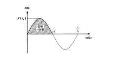
図2は、本実施形態において、低域遮断周波数の決定方法を説明するための概念図である。この図において、縦軸は振幅、横軸は時間を表す。補償帯域決定部41は、離散フーリエ変換で求めた振幅|X(fk)|と周波数fkとを用いて、数式(5)より正弦波の半周期分を時間積分したもの(=面積;図2参照)を、数式(6)のように、高域遮断周波数まで積算することで、低域遮断周波数と負荷変動補償に必要な蓄電池容量との関係を求める。そして、実効蓄電池容量(電池残量(SOC)の使用範囲として定める下限値から上限値までに対応する容量)で最も補償帯域を広くとれる低域遮断周波数を2点の線形補間により決定する。例えば、補償帯域決定部41は、上述のような補償帯域を決定する処理を1日1回実行する。FIG. 2 is a conceptual diagram for explaining a method of determining a low cut-off frequency in the present embodiment. In this figure, the vertical axis represents amplitude and the horizontal axis represents time. The compensation
次に、蓄電池制御部42が行う蓄電池制御処理について説明する。蓄電池制御部42は、例えば、蓄電池制御処理を制御周期1秒として実行する。蓄電池制御部42は、所定の蓄電池制御のアルゴリズムに従って、リアルタイム制御で、様々な周波数成分を持つ負荷電力の変動(買電電力と蓄電池出力との合計)に基づいて負荷電力の推定を行い、補償帯域決定部41によって決定された補償周波数帯域の変動を抽出して蓄電池出力指令を解き、蓄電池出力指令値を出力する(制御周期1秒)。 Next, a storage battery control process performed by the storage
より具体的には、決定補償帯域格納部30は、蓄電池補償帯域決定部22で決定した高域・低域遮断周波数を決定される毎に格納する。蓄電池出力指令値計算部31は、決定補償帯域格納部30からの高域・低域遮断周波数と、買電電力、及び蓄電池出力の合計とに基づいて、負荷電力を推定し、該推定した負荷電力に基づいて前記蓄電池の出力を制御するための蓄電池出力指令値を算出する。定置用蓄電池部13は、上記蓄電池出力指令値計算部31からの蓄電池出力指令値に従って、自身の内部に設けられた蓄電池の出力を制御する。 More specifically, the determined compensation
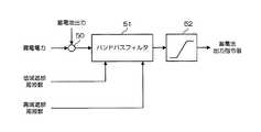
図3は、本実施形態による、蓄電池制御(蓄電池出力指令値計算部31の構成)を説明するブロック図である。蓄電池出力指令値計算部31は、加算器50と、バンドパスフィルタ51と、リミッタ52とから構成される。加算器50は、買電電力と蓄電池出力とを加算する。バンドパスフィルタ51は、低域遮断周波数と高域遮断周波数に従って、加算器50から供給される買電電力と蓄電池出力との合計値をフィルタリングする。リミッタ52は、バンドパスフィルタ51から供給される出力信号の振幅を制限し、蓄電池出力指令値として出力する。すなわち、蓄電池出力指令値計算部31では、様々な周波数成分を持つ負荷電力の変動(加算器50で加算した買電電力と蓄電池出力との合計)を、図3に示すバンドパスフィルタ51に通すことで、補償帯域の変動を抽出して蓄電池出力指令を解き、蓄電池出力指令値として出力する。この制御により、図9に示すような負荷変動補償を実現する。 FIG. 3 is a block diagram illustrating storage battery control (configuration of the storage battery output command value calculation unit 31) according to the present embodiment. The storage battery output command
なお、太陽光発電は、発電電力等を任意に制御できない電源であるので、本実施形態による制御では負の値をもつ負荷として取り扱い、図3に示す制御系に組み込まない。 Since solar power generation is a power source that cannot arbitrarily control generated power and the like, it is handled as a load having a negative value in the control according to the present embodiment, and is not incorporated into the control system shown in FIG.
次に、上述した実施形態による電力管理システム1の効果について説明する。
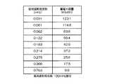
電力管理システム1の電源設備は、太陽光発電(定格出力14.3kW)と鉛蓄電池(定格出力90kW、定格容量163kWh)で構成されており、一般負荷、防災負荷、重要負荷(合計400kW程度)が接続されている。鉛蓄電池の定格蓄電池容量は、163kWhだが、蓄電池の長寿命化を考慮して電池残量(SOC)の使用範囲を30%から95%と設定しており、実効蓄電池容量は、106kWhである。Next, effects of the
The
(負荷電力取得)
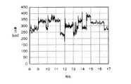
図4は、冬期の代表的な負荷電力プロファイルの一例を示す図である。この図において、縦軸は電力(負荷電力)、横軸は時刻を表しており、この図に示すような負荷電力(業務時間帯8時〜17時を対象)を気象類似日の実績データとして過去実績データDB11から取得したと仮定する。(Load power acquisition)
FIG. 4 is a diagram illustrating an example of a typical load power profile in winter. In this figure, the vertical axis represents power (load power) and the horizontal axis represents time, and load power as shown in this figure (for business hours of 8:00 to 17:00) is used as actual data on weather-like days. Suppose that it acquired from past performance data DB11.
(補償帯域決定)
高域遮断周波数については100mHzに予め決定して固定値として用い、低域遮断周波数を決定した。
図5は、図4の負荷電力を離散フーリエ変換した結果を示す図である。この図において、縦軸は負荷電力の振幅を表し、横軸は負荷電力の周波数を表す。負荷電力のサンプリング間隔Δtは1秒、サンプル数Nは2の基数になるよう、8時から17時6分7秒までを用いた。このため、サンプル数N、サンプリング間隔Δtから基本周波数f1は、数式(3)から0.031mHz、ナイキスト周波数fsは、数式(4)から500mHzとして得られる。図5では、0.031mHz刻みでナイキスト周波数500mHzまでの各周波数の振幅が観測されている。(Compensation band determination)
The high-frequency cutoff frequency was determined in advance as 100 mHz and used as a fixed value, and the low-frequency cutoff frequency was determined.
FIG. 5 is a diagram illustrating a result of discrete Fourier transform of the load power of FIG. In this figure, the vertical axis represents the load power amplitude, and the horizontal axis represents the load power frequency. The load power sampling interval Δt was 1 second, and the number of samples N was from 2 o'clock to 17: 6: 7 so that the radix was 2. For this reason, the basic frequency f1 is obtained from Equation (3) as 0.031 mHz, and the Nyquist frequency fs is obtained as 500 mHz from Equation (4) from the number of samples N and the sampling interval Δt. In FIG. 5, the amplitude of each frequency up to the Nyquist frequency of 500 mHz is observed in increments of 0.031 mHz.
離散フーリエ変換で求めた振幅|X(fk)|と周波数fkを用いて、数式(6)に従って、高域遮断周波数100mHz(数式(6)中のkは3276に相当)まで積算することで、低域遮断周波数と負荷変動補償に必要な蓄電池容量との関係を求める。Using the amplitude | X (fk ) | obtained by the discrete Fourier transform and the frequency fk , accumulating up to a high cut-off frequency of 100 mHz (k in Equation (6) corresponds to 3276) according to Equation (6). Thus, the relationship between the low-frequency cutoff frequency and the storage battery capacity necessary for load fluctuation compensation is obtained.
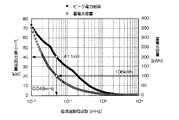
図6は、本実施形態において、低域遮断周波数と負荷変動補償に必要な蓄電池容量との関係の一例を示す図である。実効蓄電池容量が106kWhである場合、最も補償帯域を広くとれる低域遮断周波数は、この図を参照すると、0.061mHzから0.092mHzの間にあるので、この2点の線形補間を行うことで低域遮断周波数を0.066mHzに決定する。これらの計算は、一般的な表計算ソフトウェア等を用いて簡単に計算できるレベルのため、短時間で済む。 FIG. 6 is a diagram illustrating an example of the relationship between the low cutoff frequency and the storage battery capacity necessary for load variation compensation in the present embodiment. When the effective storage battery capacity is 106 kWh, referring to this figure, the low cut-off frequency that allows the widest compensation band is between 0.061 mHz and 0.092 mHz. The low cut-off frequency is determined to be 0.066 mHz. Since these calculations are at a level that can be easily calculated using general spreadsheet software or the like, a short time is required.
(蓄電池制御結果)
補償帯域決定で決定した高域・低域遮断周波数がピーク電力削減量を最大化する補償帯域であることを確認するために、MATLAB/Simulink(マトラボ(マットラブ)/シミュリンク)を用いてシミュレーションを行う。実機に実装した制御系と同一のモデルを、MATLAB/Simulink上に構築して負荷電力に対する蓄電池出力を模擬した。本実施形態では、シミュレーション結果を真値とみなす。また、シミュレーションには、図4に示した過去の実績データをリアルタイムの負荷電力として用いる。(Storage battery control result)
Simulation using MATLAB / Simlink (Matlab / Simlink) to confirm that the high / low cut-off frequency determined in compensation band determination is the compensation band that maximizes peak power reduction. I do. The same model as the control system implemented in the actual machine was built on MATLAB / Simulink to simulate the battery output relative to the load power. In the present embodiment, the simulation result is regarded as a true value. In the simulation, the past performance data shown in FIG. 4 is used as real-time load power.
図7は、本実施形態において、シミュレーションによるピーク電力削減量の算出結果を示す図であり、図7(A)は、瞬時電力での負荷変動補償結果を表し、図7(B)は、30分平均値での負荷変動補償結果を表している。図7(A)、図7(B)において、それぞれ、縦軸は電力、横軸は時刻を表す。また、図7(A)、(B)は、低域遮断周波数を0.066mHzとし、高域遮断周波数を100mHzとしたときのシミュレーション結果を示している。 FIG. 7 is a diagram showing the calculation result of the peak power reduction amount by simulation in this embodiment, FIG. 7A shows the load fluctuation compensation result with instantaneous power, and FIG. It shows the load fluctuation compensation result in the fractional average value. 7A and 7B, the vertical axis represents power, and the horizontal axis represents time. 7A and 7B show simulation results when the low-frequency cutoff frequency is 0.066 mHz and the high-frequency cutoff frequency is 100 mHz.
ピーク電力は、瞬時電力ではなく、30分間の平均値より算出されるため、図7(B)から、ピーク電力削減量は、35.2kWと推定される。また、必要となる蓄電池容量は、図7(A)に示す蓄電池出力の時間積分値の最大値であるので79.1kWhとして得ることができ、これは実効蓄電池容量106kWを下回っている。 Since the peak power is calculated not from the instantaneous power but from the average value for 30 minutes, the peak power reduction amount is estimated to be 35.2 kW from FIG. 7B. Moreover, since the required storage battery capacity is the maximum value of the time integration value of the storage battery output shown in FIG. 7A, it can be obtained as 79.1 kWh, which is lower than the effective storage battery capacity 106 kW.
図8は、同様のシミュレーションを用いて、低域遮断周波数を0.001mHz刻みで試行錯誤的に変化させたときのピーク電力削減量と蓄電池容量の推移を示す図である。この図において、縦軸はピーク電力削減量を表し、横軸は低域遮断周波数を表している。また、この図においては、高域遮断周波数を100mHzに固定した場合について図示されている。0.01mHzから10mHzまで変化させたときのシミュレーション時間は、約6時間であり、試行錯誤的であるため時間がかかる。図8に示すように、実効蓄電池容量は、106kWhなので、低域遮断周波数が0.048mHzのとき、ピーク電力削減量は、最大で41.1kWと計算される。0.066mHzのときのピーク電力削減量と比べると、5.9kWしか誤差が生じておらず、本実施形態による電力管理システム1によって十分な精度で、高速に低域遮断周波数(補償帯域)を取得することができるといえる。このように、本実施形態の電力管理システム1によれば、日々異なる負荷電力に応じて実効蓄電池容量で、最大限のピーク電力削減量が得られる運用が可能となる。 FIG. 8 is a diagram showing the transition of the peak power reduction amount and the storage battery capacity when the low cut-off frequency is changed by trial and error in increments of 0.001 mHz using the same simulation. In this figure, the vertical axis represents the peak power reduction amount, and the horizontal axis represents the low-frequency cutoff frequency. Further, in this figure, the case where the high-frequency cutoff frequency is fixed to 100 mHz is illustrated. The simulation time when changing from 0.01 mHz to 10 mHz is about 6 hours, which takes time because it is trial and error. As shown in FIG. 8, since the effective storage battery capacity is 106 kWh, when the low cut-off frequency is 0.048 mHz, the peak power reduction amount is calculated as 41.1 kW at the maximum. Compared with the peak power reduction amount at 0.066 mHz, there is only an error of 5.9 kW, and the
1 電力管理システム
2 インターネット
10 システム演算部
11 過去実績データDB
12 リアルタイムコントローラ
13 定置用蓄電池部
20 気象情報取得部
21 気象類似日負荷電力データ取得部
22 蓄電池補償帯域決定部
30 決定補償帯域格納部
31 蓄電池出力指令値計算部
40 負荷電力取得部
41 補償帯域決定部
42 蓄電池制御部1
DESCRIPTION OF
Claims (4)
Translated fromJapanese制御対象日の気象情報と類似した気象情報に対応付けられて記録されている負荷電力の過去実績データを取得する負荷電力取得部と、
前記負荷電力取得部によって取得した過去実績データに基づいて、前記蓄電池の補償周波数帯域を決定する補償帯域決定部と、
前記補償帯域決定部によって決定された前記蓄電池の補償周波数帯域と、前記買電電力、及び前記蓄電池の出力の合計とに基づいて負荷電力を推定し、該推定した負荷電力に基づいて前記蓄電池の出力を制御する蓄電池制御部と
を備え、
前記補償帯域決定部は、前記負荷電力の過去実績データから離散フーリエ変換によって各周波数の振幅を算出し、該振幅と周波数とに基づいて、低域遮断周波数と負荷変動補償に必要な蓄電池容量との関係を求め、2点の線形補間により、実効蓄電池容量で最も補償帯域を広くとれる低域遮断周波数を決定することを特徴とする電力管理システム。A power management system that controls the output of the storage battery based on the generated power generated by the power generation device and the purchased power supplied from a commercial power system,
A load power acquisition unit that acquires past performance data of load power recorded in association with weather information similar to the weather information of the control target day;
Based on past performance data acquired by the load power acquisition unit, a compensation band determination unit that determines a compensation frequency band of the storage battery,
Estimating load power based on the compensation frequency band of the storage battery determined by the compensation band determination unit, the purchased power, and the total output of the storage battery, and based on the estimated load power of the storage battery A storage battery control unit for controlling the output,
The compensation band determining unit calculates the amplitude of each frequency by discrete Fourier transform from the past performance data of the load power, and based on the amplitude and frequency, a low-frequency cutoff frequency and a storage battery capacity necessary for load fluctuation compensation, of the determined relationship, the two points the linear interpolation, the power management system characterized thatyou determine broadly take low cut-off frequency of the most compensation range with the effective battery capacity.
気象情報とその気象情報を有する日の負荷電力データとを対応付けて蓄積する過去実績データ蓄積部と、
制御対象日の気象情報を取得する気象情報取得部と、
前記気象情報取得部によって取得した制御対象日の気象情報と類似した気象情報に対応付けられて記録されている負荷電力データを、前記過去実績データ蓄積部から取得する気象類似日負荷電力データ取得部と
を備えることを特徴とする請求項1に記載の電力管理システム。The load power acquisition unit
Past performance data storage unit for storing weather information and load power data of the day having the weather information in association with each other;
A weather information acquisition unit for acquiring weather information on the control target day;
A weather-similar-day load power data acquisition unit that acquires, from the past performance data storage unit, load power data recorded in association with weather information similar to the weather information of the control target date acquired by the weather information acquisition unit The power management system according to claim 1, further comprising:
ことを特徴とする請求項1または請求項2に記載の電力管理システム。The storage battery control unit controls the output of the storage battery by filtering the total value of the purchased power and the output of the storage battery based on the compensation frequency band of the storage battery determined by the compensation band determination unit. The power management system according to claim 1or 2 , wherein a storage battery output command value is output.
制御対象日の気象情報と類似した気象情報に対応付けられて記録されている負荷電力の過去実績データを取得するステップと、
前記取得した過去実績データに基づいて、前記蓄電池の補償周波数帯域を決定するステップと、
前記決定された前記蓄電池の補償周波数帯域と、前記買電電力、及び前記蓄電池の出力の合計とに基づいて負荷電力を推定し、該推定した負荷電力に基づいて前記蓄電池の出力を制御するステップと
を備え、
前記補償周波数帯域を決定するステップは、前記負荷電力の過去実績データから離散フーリエ変換によって各周波数の振幅を算出し、該振幅と周波数とに基づいて、低域遮断周波数と負荷変動補償に必要な蓄電池容量との関係を求め、2点の線形補間により、実効蓄電池容量で最も補償帯域を広くとれる低域遮断周波数を決定することを特徴とする電力管理方法。A power management method for controlling the output of a storage battery based on generated power generated by a power generation device and purchased power supplied from a commercial power system,
Obtaining past performance data of load power recorded in association with weather information similar to the weather information of the control target day;
Determining a compensation frequency band of the storage battery based on the acquired past performance data;
Estimating load power based on the determined compensation frequency band of the storage battery, the purchased power, and the output of the storage battery, and controlling the output of the storage battery based on the estimated load power It equipped with adoor,
The step of determining the compensation frequency band calculates the amplitude of each frequency by discrete Fourier transform from the past performance data of the load power, and based on the amplitude and frequency, is necessary for low-frequency cutoff frequency and load fluctuation compensation obtained relation between battery capacity, by the two-point linear interpolation, power management method, wherein thatyou determine broadly take low cut-off frequency of the most compensation range with the effective battery capacity.
Priority Applications (1)
| Application Number | Priority Date | Filing Date | Title |
|---|---|---|---|
| JP2013052494AJP6032486B2 (en) | 2013-03-14 | 2013-03-14 | Power management system and power management method |
Applications Claiming Priority (1)
| Application Number | Priority Date | Filing Date | Title |
|---|---|---|---|
| JP2013052494AJP6032486B2 (en) | 2013-03-14 | 2013-03-14 | Power management system and power management method |
Publications (2)
| Publication Number | Publication Date |
|---|---|
| JP2014180134A JP2014180134A (en) | 2014-09-25 |
| JP6032486B2true JP6032486B2 (en) | 2016-11-30 |
Family
ID=51699496
Family Applications (1)
| Application Number | Title | Priority Date | Filing Date |
|---|---|---|---|
| JP2013052494AActiveJP6032486B2 (en) | 2013-03-14 | 2013-03-14 | Power management system and power management method |
Country Status (1)
| Country | Link |
|---|---|
| JP (1) | JP6032486B2 (en) |
Families Citing this family (7)
| Publication number | Priority date | Publication date | Assignee | Title |
|---|---|---|---|---|
| JP6555504B2 (en)* | 2015-01-13 | 2019-08-07 | 清水建設株式会社 | Power management system and power management method |
| JP6555505B2 (en)* | 2015-01-13 | 2019-08-07 | 清水建設株式会社 | Power management system and power management method |
| JP6544554B2 (en)* | 2015-01-13 | 2019-07-17 | 清水建設株式会社 | Power management system, power management method |
| JP6524515B2 (en)* | 2015-02-24 | 2019-06-05 | 清水建設株式会社 | POWER MANAGEMENT SYSTEM AND POWER MANAGEMENT METHOD |
| JP6404747B2 (en)* | 2015-03-02 | 2018-10-17 | 愛知電機株式会社 | Design method of power transfer function in power leveling system and calculation method of storage battery capacity in power leveling system |
| JP6432780B2 (en)* | 2015-03-03 | 2018-12-05 | 清水建設株式会社 | Power management system and power management method |
| JP6481823B2 (en)* | 2015-04-30 | 2019-03-13 | 清水建設株式会社 | Power management system and power management method |
Family Cites Families (4)
| Publication number | Priority date | Publication date | Assignee | Title |
|---|---|---|---|---|
| JP4858799B2 (en)* | 2005-03-02 | 2012-01-18 | 清水建設株式会社 | Control method of distributed power supply |
| JP2011101553A (en)* | 2009-11-09 | 2011-05-19 | Shimizu Corp | Energy storage system |
| JP2011114944A (en)* | 2009-11-26 | 2011-06-09 | Fuji Electric Systems Co Ltd | Power demand estimation device, and program of the same |
| JP5626563B2 (en)* | 2010-05-31 | 2014-11-19 | 清水建設株式会社 | Power system |
- 2013
- 2013-03-14JPJP2013052494Apatent/JP6032486B2/enactiveActive
Also Published As
| Publication number | Publication date |
|---|---|
| JP2014180134A (en) | 2014-09-25 |
Similar Documents
| Publication | Publication Date | Title |
|---|---|---|
| JP6032486B2 (en) | Power management system and power management method | |
| Tang et al. | Estimation and validation of characteristic load profile through smart grid trials in a medium voltage distribution network | |
| CN109687447B (en) | Electric power energy consumption prediction method and device | |
| CN114140176A (en) | A method and device for predicting the adjustable capacity of a load gathering platform | |
| CN111242805A (en) | Method and device for calculating growth rate of electricity consumption | |
| CN120222437A (en) | Distributed energy storage power system optimization scheduling method and system | |
| CN119324466B (en) | Time sequence power grid planning method based on new energy consumption rate | |
| CN119209652B (en) | Water-light-storage-integration-based energy charge and discharge control method and system | |
| CN116169791A (en) | Power grid operation safety detection system containing pumped storage power station | |
| CN109345147B (en) | A method, system and device for evaluating the operating efficiency of a distribution network transformer | |
| JP6372690B2 (en) | Power management system and power management method | |
| CN118889499B (en) | Load tracking method, device, electronic equipment and medium based on energy storage EMS system | |
| JP2015032067A (en) | Storage battery introduction effect evaluation device, storage battery introduction effect evaluation method, and program | |
| KR20220157577A (en) | Solar pv capacity estimation method and apparatuses operating the same | |
| Hassan et al. | A comparison of the forecast performance of double seasonal ARIMA and double seasonal ARFIMA models of electricity load demand | |
| JP6555504B2 (en) | Power management system and power management method | |
| Schaede et al. | Electric energy storages–a method for specification, design and assessment | |
| CN117937522B (en) | Power energy-saving control method of power control cabinet, control cabinet and storage medium | |
| CN115940138B (en) | User load short-term prediction method and system based on high-frequency data | |
| JP6555505B2 (en) | Power management system and power management method | |
| CN120433215B (en) | A deep well pump operation frequency conversion control method and system | |
| CN120030263B (en) | A method, device and medium for locating abnormal line loss in a transformer area based on multi-dimensional analysis | |
| CN113985125B (en) | Method, device and equipment for calculating electric quantity with few abnormal current climbing | |
| CN119582348B (en) | Electric power energy consumption monitoring method | |
| JP6524515B2 (en) | POWER MANAGEMENT SYSTEM AND POWER MANAGEMENT METHOD |
Legal Events
| Date | Code | Title | Description |
|---|---|---|---|
| A621 | Written request for application examination | Free format text:JAPANESE INTERMEDIATE CODE: A621 Effective date:20151118 | |
| A977 | Report on retrieval | Free format text:JAPANESE INTERMEDIATE CODE: A971007 Effective date:20160707 | |
| A131 | Notification of reasons for refusal | Free format text:JAPANESE INTERMEDIATE CODE: A131 Effective date:20160712 | |
| A521 | Written amendment | Free format text:JAPANESE INTERMEDIATE CODE: A523 Effective date:20160830 | |
| TRDD | Decision of grant or rejection written | ||
| A01 | Written decision to grant a patent or to grant a registration (utility model) | Free format text:JAPANESE INTERMEDIATE CODE: A01 Effective date:20160920 | |
| A61 | First payment of annual fees (during grant procedure) | Free format text:JAPANESE INTERMEDIATE CODE: A61 Effective date:20161012 | |
| R150 | Certificate of patent or registration of utility model | Ref document number:6032486 Country of ref document:JP Free format text:JAPANESE INTERMEDIATE CODE: R150 |