JP6029521B2 - Photoacoustic wave measuring apparatus, method, program, and recording medium - Google Patents
Photoacoustic wave measuring apparatus, method, program, and recording mediumDownload PDFInfo
- Publication number
- JP6029521B2 JP6029521B2JP2013084519AJP2013084519AJP6029521B2JP 6029521 B2JP6029521 B2JP 6029521B2JP 2013084519 AJP2013084519 AJP 2013084519AJP 2013084519 AJP2013084519 AJP 2013084519AJP 6029521 B2JP6029521 B2JP 6029521B2
- Authority
- JP
- Japan
- Prior art keywords
- photoacoustic wave
- electrical signal
- measurement
- photoacoustic
- measuring
- Prior art date
- Legal status (The legal status is an assumption and is not a legal conclusion. Google has not performed a legal analysis and makes no representation as to the accuracy of the status listed.)
- Active
Links
- 238000000034methodMethods0.000titleclaimsdescription19
- 238000005259measurementMethods0.000claimsdescription169
- 238000001514detection methodMethods0.000claimsdescription79
- 239000008280bloodSubstances0.000description104
- 210000004369bloodAnatomy0.000description104
- 239000013307optical fiberSubstances0.000description40
- 230000000630rising effectEffects0.000description9
- 210000004204blood vesselAnatomy0.000description8
- 238000010586diagramMethods0.000description7
- 230000004048modificationEffects0.000description6
- 238000012986modificationMethods0.000description6
- 125000006850spacer groupChemical group0.000description3
- 239000000463materialSubstances0.000description2
- 210000001015abdomenAnatomy0.000description1
- 230000000694effectsEffects0.000description1
- 230000001902propagating effectEffects0.000description1
Images


Classifications
- A—HUMAN NECESSITIES
- A61—MEDICAL OR VETERINARY SCIENCE; HYGIENE
- A61B—DIAGNOSIS; SURGERY; IDENTIFICATION
- A61B5/00—Measuring for diagnostic purposes; Identification of persons
- A61B5/0093—Detecting, measuring or recording by applying one single type of energy and measuring its conversion into another type of energy
- A61B5/0095—Detecting, measuring or recording by applying one single type of energy and measuring its conversion into another type of energy by applying light and detecting acoustic waves, i.e. photoacoustic measurements
- A—HUMAN NECESSITIES
- A61—MEDICAL OR VETERINARY SCIENCE; HYGIENE
- A61B—DIAGNOSIS; SURGERY; IDENTIFICATION
- A61B5/00—Measuring for diagnostic purposes; Identification of persons
- A61B5/48—Other medical applications
- A61B5/4887—Locating particular structures in or on the body
- A61B5/489—Blood vessels
Landscapes
- Health & Medical Sciences (AREA)
- Life Sciences & Earth Sciences (AREA)
- Physics & Mathematics (AREA)
- Molecular Biology (AREA)
- Animal Behavior & Ethology (AREA)
- Pathology (AREA)
- Engineering & Computer Science (AREA)
- Biomedical Technology (AREA)
- Heart & Thoracic Surgery (AREA)
- Medical Informatics (AREA)
- Veterinary Medicine (AREA)
- Surgery (AREA)
- Biophysics (AREA)
- General Health & Medical Sciences (AREA)
- Public Health (AREA)
- Acoustics & Sound (AREA)
- Vascular Medicine (AREA)
- Ultra Sonic Daignosis Equipment (AREA)
- Investigating Or Analyzing Materials By The Use Of Ultrasonic Waves (AREA)
- Measurement Of Velocity Or Position Using Acoustic Or Ultrasonic Waves (AREA)
Description
Translated fromJapanese本発明は、光音響センサを用いたターゲットの位置測定に関する。 The present invention relates to target position measurement using a photoacoustic sensor.
従来より、2個以上の光音響センサを用いて光音響波を検出することにより、測定対象を測定することが知られている(例えば、特許文献1を参照)。光音響センサは、光を測定対象に照射する。すると、測定対象内のターゲットに光が吸収される。これにより、ターゲット(光音響波発生部分)が光音響波を発生する。この光音響波を光音響センサが検出する。ターゲットの真上に光音響センサが位置すると、光音響波を検出できる。これにより、ターゲットの位置を測定することができる。 Conventionally, it is known to measure a measurement object by detecting a photoacoustic wave using two or more photoacoustic sensors (see, for example, Patent Document 1). A photoacoustic sensor irradiates light to a measuring object. Then, light is absorbed by the target in the measurement target. As a result, the target (photoacoustic wave generation portion) generates a photoacoustic wave. A photoacoustic sensor detects this photoacoustic wave. When the photoacoustic sensor is positioned directly above the target, a photoacoustic wave can be detected. Thereby, the position of the target can be measured.
しかしながら、ターゲット(光音響波発生部分)が発生する光音響波は、ターゲットの真上にのみ伝搬するわけではなく、ターゲットの斜め上方にも伝搬する。よって、光音響センサがターゲットの斜め上方に伝搬する光音響波を検出してしまった場合、光音響センサの真下にはターゲットが無い。このような場合には、ターゲットの位置の測定に誤差が生じる。 However, the photoacoustic wave generated by the target (photoacoustic wave generating portion) does not propagate only directly above the target, but also propagates obliquely above the target. Therefore, when the photoacoustic sensor detects a photoacoustic wave propagating obliquely above the target, there is no target directly under the photoacoustic sensor. In such a case, an error occurs in the measurement of the target position.
そこで、本発明は、光音響測定器による光音響波発生部分の位置の測定を正確に行うことを課題とする。 Therefore, an object of the present invention is to accurately measure the position of a photoacoustic wave generation portion by a photoacoustic measuring instrument.
本発明にかかる光音響波測定装置は、光を出力する光出力部と、前記光により前記測定対象において発生した光音響波を受けて電気信号に変換する複数の光音響波検知部とを有する光音響波測定器から前記電気信号を受ける光音響波測定装置であって、前記光音響波検知部の各々が出力する前記電気信号の時間のずれが所定範囲内にあるかを判定する時間ずれ判定部と、前記時間ずれ判定部により、前記電気信号の時間のずれが前記所定範囲内にあると判定された場合に、前記測定対象において前記光音響波が発生した光音響波発生部分の位置を測定する位置測定部とを備えるように構成される。 A photoacoustic wave measurement device according to the present invention includes a light output unit that outputs light, and a plurality of photoacoustic wave detection units that receive a photoacoustic wave generated in the measurement target by the light and convert the light into an electric signal. A photoacoustic wave measurement device that receives the electrical signal from a photoacoustic wave measuring instrument, wherein the time shift determines whether a time shift of the electrical signal output by each of the photoacoustic wave detection units is within a predetermined range. The position of the photoacoustic wave generation portion where the photoacoustic wave is generated in the measurement target when the determination unit and the time shift determination unit determine that the time shift of the electrical signal is within the predetermined range. And a position measuring unit for measuring.
上記のように構成された光音響波測定装置によれば、光を出力する光出力部と、前記光により前記測定対象において発生した光音響波を受けて電気信号に変換する複数の光音響波検知部とを有する光音響波測定器から前記電気信号を受ける光音響波測定装置が提供される。時間ずれ判定部が、前記光音響波検知部の各々が出力する前記電気信号の時間のずれが所定範囲内にあるかを判定する。位置測定部が、前記時間ずれ判定部により、前記電気信号の時間のずれが前記所定範囲内にあると判定された場合に、前記測定対象において前記光音響波が発生した光音響波発生部分の位置を測定する。 According to the photoacoustic wave measuring apparatus configured as described above, a light output unit that outputs light, and a plurality of photoacoustic waves that receive the photoacoustic wave generated in the measurement object by the light and convert the photoacoustic wave into an electrical signal. There is provided a photoacoustic wave measuring apparatus that receives the electric signal from a photoacoustic wave measuring instrument having a detection unit. A time shift determination unit determines whether a time shift of the electrical signal output from each of the photoacoustic wave detection units is within a predetermined range. When the position measurement unit determines that the time shift of the electrical signal is within the predetermined range by the time shift determination unit, the photoacoustic wave generation portion where the photoacoustic wave is generated in the measurement target Measure the position.
なお、本発明にかかる光音響波測定装置は、前記位置測定部が、前記光出力部の延長線上に前記光音響波発生部分が存在するものとして、前記光音響波発生部分の位置を測定するようにしてもよい。 In the photoacoustic wave measurement apparatus according to the present invention, the position measurement unit measures the position of the photoacoustic wave generation part on the assumption that the photoacoustic wave generation part exists on an extension line of the light output unit. You may do it.
なお、本発明にかかる光音響波測定装置は、前記所定範囲が、0以上かつ所定の時間閾値以下の範囲であるようにしてもよい。 In the photoacoustic wave measuring apparatus according to the present invention, the predetermined range may be a range of 0 or more and a predetermined time threshold or less.
なお、本発明にかかる光音響波測定装置は、前記所定範囲が、前記光出力部の延長線上に前記光音響波発生部分が存在したと仮定した場合の前記光音響波検知部の各々が出力する前記電気信号の時間のずれを含むようにしてもよい。 In the photoacoustic wave measurement device according to the present invention, each of the photoacoustic wave detection units outputs the predetermined range when it is assumed that the photoacoustic wave generation part exists on an extension line of the light output unit. The time difference of the electrical signal may be included.
なお、本発明にかかる光音響波測定装置は、前記所定範囲が0を含まないようにしてもよい。 In the photoacoustic wave measuring apparatus according to the present invention, the predetermined range may not include zero.
なお、本発明にかかる光音響波測定装置は、前記光音響波検知部の各々が出力する前記電気信号の大きさと、所定の大きさ閾値との大小関係を判定する大きさ判定部を備え、前記位置測定部が、前記大きさ判定部により、前記電気信号の大きさが前記大きさ閾値を超えていると判定され、かつ、前記時間ずれ判定部により、前記電気信号の時間のずれが前記所定範囲内にあると判定された場合に、前記測定対象において前記光音響波が発生した光音響波発生部分の位置を測定するようにしてもよい。 The photoacoustic wave measurement device according to the present invention includes a magnitude determination unit that determines the magnitude relationship between the magnitude of the electrical signal output from each of the photoacoustic wave detection units and a predetermined magnitude threshold, The position measuring unit is determined by the magnitude determining unit that the magnitude of the electrical signal exceeds the magnitude threshold, and the time lag judging unit is configured to detect a time lag of the electrical signal. When it is determined to be within a predetermined range, the position of the photoacoustic wave generation portion where the photoacoustic wave is generated in the measurement target may be measured.
本発明は、光を出力する光出力部と、前記光により前記測定対象において発生した光音響波を受けて電気信号に変換する複数の光音響波検知部とを有する光音響波測定器から前記電気信号を受けて光音響波を測定する光音響波測定方法であって、前記光音響波検知部の各々が出力する前記電気信号の時間のずれが所定範囲内にあるかを判定する時間ずれ判定工程と、前記時間ずれ判定工程により、前記電気信号の時間のずれが前記所定範囲内にあると判定された場合に、前記測定対象において前記光音響波が発生した光音響波発生部分の位置を測定する位置測定工程とを備えた光音響波測定方法である。 The present invention relates to a photoacoustic wave measuring instrument comprising: a light output unit that outputs light; and a plurality of photoacoustic wave detection units that receive a photoacoustic wave generated in the measurement target by the light and convert the photoacoustic wave into an electrical signal. A photoacoustic wave measuring method for measuring a photoacoustic wave in response to an electric signal, wherein a time shift for determining whether a time shift of the electric signal output from each of the photoacoustic wave detection units is within a predetermined range The position of the photoacoustic wave generation portion where the photoacoustic wave is generated in the measurement object when it is determined by the determination step and the time shift determination step that the time shift of the electrical signal is within the predetermined range. It is a photoacoustic wave measuring method provided with the position measurement process of measuring.
本発明は、光を出力する光出力部と、前記光により前記測定対象において発生した光音響波を受けて電気信号に変換する複数の光音響波検知部とを有する光音響波測定器から前記電気信号を受けて光音響波を測定する光音響波測定処理をコンピュータに実行させるためのプログラムであって、前記光音響波測定処理は、前記光音響波検知部の各々が出力する前記電気信号の時間のずれが所定範囲内にあるかを判定する時間ずれ判定工程と、前記時間ずれ判定工程により、前記電気信号の時間のずれが前記所定範囲内にあると判定された場合に、前記測定対象において前記光音響波が発生した光音響波発生部分の位置を測定する位置測定工程とを備えたプログラムである。 The present invention relates to a photoacoustic wave measuring instrument comprising: a light output unit that outputs light; and a plurality of photoacoustic wave detection units that receive a photoacoustic wave generated in the measurement target by the light and convert the photoacoustic wave into an electrical signal. A program for causing a computer to execute a photoacoustic wave measurement process for measuring a photoacoustic wave in response to an electric signal, wherein the photoacoustic wave measurement process is performed by each of the photoacoustic wave detection units. When the time lag determination step for determining whether the time lag of the electric signal is within a predetermined range and the time lag determination step determine that the time lag of the electrical signal is within the predetermined range, the measurement And a position measuring step for measuring a position of a photoacoustic wave generation portion where the photoacoustic wave is generated in the object.
本発明は、光を出力する光出力部と、前記光により前記測定対象において発生した光音響波を受けて電気信号に変換する複数の光音響波検知部とを有する光音響波測定器から前記電気信号を受けて光音響波を測定する光音響波測定処理をコンピュータに実行させるためのプログラムを記録したコンピュータによって読み取り可能な記録媒体であって、前記光音響波測定処理は、前記光音響波検知部の各々が出力する前記電気信号の時間のずれが所定範囲内にあるかを判定する時間ずれ判定工程と、前記時間ずれ判定工程により、前記電気信号の時間のずれが前記所定範囲内にあると判定された場合に、前記測定対象において前記光音響波が発生した光音響波発生部分の位置を測定する位置測定工程とを備えた記録媒体である。 The present invention relates to a photoacoustic wave measuring instrument comprising: a light output unit that outputs light; and a plurality of photoacoustic wave detection units that receive a photoacoustic wave generated in the measurement target by the light and convert the photoacoustic wave into an electrical signal. A computer-readable recording medium storing a program for causing a computer to execute a photoacoustic wave measurement process for measuring a photoacoustic wave in response to an electric signal, wherein the photoacoustic wave measurement process includes the photoacoustic wave measurement process. A time lag determining step for determining whether a time lag of the electrical signal output by each of the detection units is within a predetermined range, and a time lag determining step, the time lag of the electric signal is within the predetermined range. And a position measuring step of measuring a position of a photoacoustic wave generation portion where the photoacoustic wave is generated in the measurement target when it is determined to be present.
以下、本発明の実施形態を図面を参照しながら説明する。 Embodiments of the present invention will be described below with reference to the drawings.
第一の実施形態
図1は、本発明の第一の実施形態にかかる光音響波測定器1の断面図である。図2は、本発明の第一の実施形態にかかる光音響波測定器1の平面図である。光音響波測定器1は、光音響波検知部11、12、光ファイバ(光出力部)20を備える。光音響波測定器1は、測定対象2に接しており、測定対象2の上を例えば左から右に走査する。First Embodiment FIG. 1 is a cross-sectional view of a photoacoustic
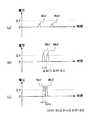
図1(a)が、血液2aから遠くに位置する光音響波測定器1を示す。図1(a)に図示の光音響波測定器1を右に走査すると、図1(b)に示すように、血液2aからやや遠くに位置するようになる。図1(b)に図示の光音響波測定器1を右に走査すると、図1(c)に示すように、血液2aの真上に位置するようになる。 Fig.1 (a) shows the photoacoustic
光ファイバ(光出力部)20は、光(例えば、パルス光Pであるが連続光とすることも考えられる)を出力する。なお、光ファイバ20は、光音響波測定器1の外部のパルス光源(図示省略)に接続されている。光ファイバ20は、光音響波測定器1を貫通する。また、光ファイバ20が出力するパルス光Pは、図示の便宜上、図1(c)の場合のみ図示している。 The optical fiber (light output unit) 20 outputs light (for example, pulsed light P but may be continuous light). The
測定対象2は、例えば人間の指の腹である。測定対象2には血管内の血液2aがあり、血管内の血液2aがパルス光Pを受けると、光音響波Wa1、Wa2(図1(a)参照)、光音響波Wb1、Wb2(図1(b)参照)、光音響波Wc1、Wc2(図1(c)参照)を発生する。 The
光音響波検知部11、12は、光音響波Wa1、Wa2、Wb1、Wb2、Wc1、Wc2を受けて、電気信号(例えば、電圧)に変換する。光音響波検知部11、12は、複数あるものとする。例えば、図1および図2に図示したように、光音響波検知部11、12は、2個あるものとする。 The photoacoustic
光音響波検知部11、12は、それぞれが、図示省略した周知のバッキング材、圧電素子、電極およびスペーサを有する。スペーサは測定対象2に接し、電極はスペーサに載せられ、圧電素子は電極に載せられ、バッキング材は圧電素子に載せられている。光音響波Wa1、Wa2、Wb1、Wb2、Wc1、Wc2が、圧電素子により電気信号(例えば、電圧)に変換され、電極を介して、外部に取り出される。 Each of the photoacoustic
なお、図2を参照して、光音響波検知部11、12は、光ファイバ20から、走査方向に、共に距離X0だけ離れている。 2, the photoacoustic
図3は、本発明の第一の実施形態にかかる光音響波測定装置40の構成を示す機能ブロック図である。光音響波測定装置40は、電気信号測定部41、42、大きさ判定部44、時間ずれ判定部46、位置測定部48を備える。光音響波測定装置40は、光音響波測定器1の光音響波検知部11、12から電気信号を受ける。 FIG. 3 is a functional block diagram showing the configuration of the photoacoustic
電気信号測定部41は、光音響波検知部11から電気信号を受け、その測定結果(例えば、時間と電圧との関係)を出力する(図4のWa1、Wb1、Wc1参照)。電気信号測定部42は、光音響波検知部12から電気信号を受け、その測定結果(例えば、時間と電圧との関係)を出力する(図4のWa2、Wb2、Wc2参照)。 The electrical
大きさ判定部44は、光音響波検知部11、12の各々が出力する電気信号の測定結果を、電気信号測定部41、42から受ける。そして、大きさ判定部44は、電気信号測定部41、42から受けた測定結果から、光音響波検知部11、12の各々が出力する電気信号の大きさと、所定の大きさ閾値ΔVとの大小関係を判定する。 The
例えば、大きさ判定部44は、光音響波検知部11、12の各々が出力する電気信号の大きさが、いずれも所定の大きさ閾値ΔVを超えているか否か(またはΔV以上か否か)を判定する。 For example, the
ここで、光音響波検知部11、12の各々が出力する電気信号の大きさが、いずれも所定の大きさ閾値ΔVを超えていると判定された場合は、大きさ判定部44は、電気信号測定部41、42から受けた測定結果を、時間ずれ判定部46に与える。 Here, when it is determined that the magnitudes of the electrical signals output from the photoacoustic
一方、光音響波検知部11、12の各々が出力する電気信号の大きさのいずれか一つ以上が、所定の大きさ閾値ΔV以下であると判定された場合(図4(a)参照)は、大きさ判定部44は、電気信号測定部41、42から受けた測定結果を、時間ずれ判定部46に与えない。この場合、大きさ判定部44は、光音響波測定器1が血液2aから遠くに位置する旨の判定結果(図1(a)参照)を出力するようにしてもよい。 On the other hand, when it is determined that any one or more of the magnitudes of the electrical signals output from the photoacoustic
時間ずれ判定部46は、大きさ判定部44を介して、電気信号測定部41、42から測定結果を受ける。そして、時間ずれ判定部46は、電気信号測定部41、42から受けた測定結果から、光音響波検知部11、12の各々が出力する電気信号の時間のずれが所定範囲内(例えば、0以上かつ所定の時間閾値Δt以下)にあるかを判定する。 The time
例えば、時間ずれ判定部46は、光音響波検知部11、12の各々が出力する電気信号の立ち上がり時点の時間のずれが、0以上かつ所定の時間閾値Δt以下か否か(または0以上かつΔt未満か否か)を判定する。 For example, the time
ここで、光音響波検知部11、12の各々が出力する電気信号の立ち上がり時点の時間のずれΔtcが、0以上かつ所定の時間閾値Δt以下であると判定された場合(図4(c)参照)は、時間ずれ判定部46は、光音響波測定器1が血液2aの真上に位置する旨の判定結果(図1(c)参照)を位置測定部48に出力する。 Here, when it is determined that the time lag Δtc at the rising point of the electrical signal output from each of the photoacoustic
一方、光音響波検知部11、12の各々が出力する電気信号の立ち上がり時点の時間のずれΔtbが、所定の時間閾値Δtを超えると判定された場合(図4(b)参照)は、時間ずれ判定部46は、位置測定部48に特に何も出力しない。この場合、時間ずれ判定部46は、光音響波測定器1が血液2aからやや遠くに位置する旨の判定結果(図1(b)参照)を出力するようにしてもよい。 On the other hand, when it is determined that the time lag Δtb at the rising time of the electrical signal output from each of the photoacoustic
なお、時間ずれ判定部46が、光音響波測定器1が血液2aの真上に位置する旨の判定結果(図1(c)参照)を位置測定部48に与えるということは、大きさ判定部44により、光音響波検知部11、12の各々が出力する電気信号の大きさが大きさ閾値ΔVを超えていると判定され、かつ、時間ずれ判定部46により、光音響波検知部11、12の各々が出力する電気信号の時間のずれが所定範囲内(0以上かつ所定の時間閾値Δt以下)にあると判定されたということを意味する。 The time
位置測定部48は、時間ずれ判定部46から光音響波測定器1が血液2aの真上に位置する旨の判定結果(図1(c)参照)を受けた場合に、測定対象2において光音響波Wc1、Wc2が発生した血液2a(光音響波発生部分)の位置を測定する。 When the
この場合、位置測定部48は、光ファイバ(光出力部)20の延長線上(例えば、真下)に血液2a(光音響波発生部分)が存在するものとして、血液2a(光音響波発生部分)の位置を測定する。位置測定部48は、電気信号測定部41、42から測定結果を受け、血液2a(光音響波発生部分)の位置を測定する。例えば、測定対象2の表面を基準とした血液2aの深さdを測定することができる。電気信号測定部41、42から受けた測定結果から、血液2aから光音響波検知部11に光音響波Wc1が到達するのにかかった時間と、血液2aから光音響波検知部12に光音響波Wc2が到達するのにかかった時間とが共にTであったことが分かったとする。すると、測定対象2内における光音響波の速度をVsとした場合、(T×Vs)2=d2+X02となる。X0およびVsは既知であるため、血液2aの深さdを求めることができる。In this case, the
次に、本発明の第一の実施形態の動作を説明する。 Next, the operation of the first embodiment of the present invention will be described.
まず、動作説明の前に、図1(a)、図1(b)および図1(c)における光音響波測定器1の血液2aに対する位置関係と、電気信号を大きさ閾値ΔVおよび時間閾値Δtと比較した結果との関係を表1に示す。 First, before explaining the operation, the positional relationship of the photoacoustic

ここで、外部のパルス光源(図示省略)がパルス光Pを発し、パルス光Pが光ファイバ20から出力される。パルス光Pは、測定対象2に与えられる。 Here, an external pulse light source (not shown) emits pulsed light P, and the pulsed light P is output from the
パルス光Pは測定対象2の血管内の血液2aに到達する。すると、血管内の血液2aがパルス光Pを吸収し、血管内の血液2aから疎密波(光音響波Wa1、Wa2)が出力される。 The pulsed light P reaches the
光音響波Wa1、Wa2は、測定対象2を透過し、光音響波検知部11、12に到達する。光音響波検知部11、12は、光音響波Wa1、Wa2による圧力を、電気信号(例えば、電圧)に変換する。この電圧が、光音響波測定装置40の電気信号測定部41、42に与えられる。 The photoacoustic waves Wa1 and Wa2 pass through the
図4は、第一の実施形態にかかる光音響波測定装置40の電気信号測定部41、42の測定結果である時間と電圧との関係を示す図であり、図1(a)における光音響波測定器1から得られた電気信号の測定結果(図4(a))、図1(b)における光音響波測定器1から得られた電気信号の測定結果(図4(b))および図1(c)における光音響波測定器1から得られた電気信号の測定結果(図4(c))を示す図である。 FIG. 4 is a diagram showing the relationship between time and voltage, which is a measurement result of the electrical
(a)光音響波測定器1が血液2aから遠い場合
図1(a)に示すように、光音響波測定器1は、血液2aから遠い。よって、光音響波Wa1、Wa2は微弱であり、光音響波Wa1、Wa2から得られた電気信号(電圧)の大きさも小さく、いずれも大きさ閾値ΔV以下である(図4(a)参照)。(A) When the photoacoustic
この場合、大きさ判定部44は、電気信号測定部41、42から受けた測定結果を、時間ずれ判定部46に与えない。大きさ判定部44は、光音響波測定器1が血液2aから遠くに位置する旨の判定結果(図1(a)参照)を出力する。 In this case, the
(b)光音響波測定器1が血液2aからやや遠い場合
図1(a)に示す状態から、光音響波測定器1を走査すると、図1(b)に示すように、光音響波測定器1は血液2aからやや遠くに位置するようになる。(B) When the photoacoustic
図1(b)に示すように、光音響波測定器1は、血液2aからやや遠いものの、図1(a)に示す状態よりは血液2aに近くなる。よって、光音響波Wb1、Wb2は、光音響波Wa1、Wa2よりも強くなり、光音響波Wb1、Wb2から得られた電気信号(電圧)の大きさが、いずれも大きさ閾値ΔVを超える(図4(b)参照)。 As shown in FIG. 1B, the photoacoustic
この場合、大きさ判定部44は、電気信号測定部41、42から受けた測定結果を、時間ずれ判定部46に与える。 In this case, the
図1(b)に示すように、光音響波測定器1は、血液2aからやや遠いため、光音響波Wb1の進行する距離と、光音響波Wb2の進行する距離との差異は無視できない。よって、光音響波Wb1が光音響波検知部11に到達する時間と、光音響波Wb2が光音響波検知部12に到達する時間との差異も無視できない。これにより、図4(b)を参照して、光音響波Wb1、Wb2から得られた電気信号の立ち上がり時点の時間のずれΔtbは無視できない(例えば、所定の時間閾値Δtを超える)。 As shown in FIG. 1B, since the photoacoustic
この場合、時間ずれ判定部46は、位置測定部48に特に何も出力しない。時間ずれ判定部46は、光音響波測定器1が血液2aからやや遠くに位置する旨の判定結果(図1(b)参照)を出力する。 In this case, the time
(c)光音響波測定器1が血液2aの真上にある場合
図1(b)に示す状態から、光音響波測定器1を走査すると、図1(c)に示すように、光音響波測定器1は血液2aの真上に位置するようになる。(C) When the photoacoustic
図1(c)に示すように、光音響波測定器1は、図1(a)に示す状態よりも血液2aに近くなる。よって、光音響波Wc1、Wc2は、光音響波Wa1、Wa2よりも強くなり、光音響波Wc1、Wc2から得られた電気信号(電圧)の大きさが、いずれも大きさ閾値ΔVを超える(図4(c)参照)。 As shown in FIG. 1C, the photoacoustic
この場合、大きさ判定部44は、電気信号測定部41、42から受けた測定結果を、時間ずれ判定部46に与える。 In this case, the
図1(c)に示すように、光音響波測定器1は、血液2aの真上にある。しかも、図2を参照して、光音響波検知部11と光ファイバ20との距離と、光音響波検知部12と光ファイバ20との距離とは共にX0であり等しい。このため、光音響波Wc1の進行する距離と、光音響波Wc2の進行する距離とは等しい。よって、光音響波Wc1が光音響波検知部11に到達する時間と、光音響波Wc2が光音響波検知部12に到達する時間とは等しい。これにより、図4(c)を参照して、光音響波Wc1、Wc2から得られた電気信号の立ち上がり時点の時間のずれΔtcは無視できるほど小さい(例えば、所定の時間閾値Δt以下である)。 As shown in FIG. 1 (c), the photoacoustic
この場合、時間ずれ判定部46は、光音響波測定器1が血液2aの真上に位置する旨の判定結果(図1(c)参照)を位置測定部48に出力する。位置測定部48は、光ファイバ20の延長線上(例えば、真下)に血液2a(光音響波発生部分)が存在するものとして、血液2a(光音響波発生部分)の位置を測定する。位置測定部48は、電気信号測定部41、42から測定結果を受け、血液2a(光音響波発生部分)の位置を測定する(例えば、血液2aの深さdを測定する)。 In this case, the time
第一の実施形態によれば、光音響波測定器1の光ファイバ20の延長線上(例えば、真下)に血液2a(光音響波発生部分)が存在するか(図1(c)参照)、しないか(図1(a)、(b)参照)を判定することができる。 According to the first embodiment, whether
しかも、光音響波測定装置40は、光音響波測定器1の光ファイバ20の延長線上に血液2aが存在するものとして、位置測定部48が血液2aの位置を測定する。ここで、光音響波測定装置40は、実際に光音響波測定器1の光ファイバ20の延長線上に血液2aが存在する場合(図1(c)参照)に、かかる測定を行う。よって、光音響測定器1による血液2aの位置の測定を正確に行うことができる。 Moreover, in the photoacoustic
なお、第一の実施形態において、光音響波測定装置40が大きさ判定部44を備えるものとして説明してきた。しかし、光音響波測定装置40が大きさ判定部44を備えない変形例も考えられる。 In the first embodiment, the photoacoustic
図9は、本発明の第一の実施形態の変形例にかかる光音響波測定装置40の構成を示す機能ブロック図である。本発明の第一の実施形態の変形例にかかる光音響波測定装置40は、電気信号測定部41、42、時間ずれ判定部46、位置測定部48を備える。 FIG. 9 is a functional block diagram showing a configuration of the photoacoustic
電気信号測定部41、42、位置測定部48は、第一の実施形態(図3参照)と同様であり説明を省略する。 The electric
時間ずれ判定部46は、電気信号測定部41、42から直接(大きさ判定部44を介さないで)、測定結果を受ける。時間ずれ判定部46による判定法は、第一の実施形態と同様であり説明を省略する。 The time
ただし、時間ずれ判定部46により、光音響波検知部11、12の各々が出力する電気信号の立ち上がり時点の時間のずれΔtbが、所定の時間閾値Δtを超えると判定された場合は、時間ずれ判定部46は、光音響波測定器1が血液2aから遠くに位置する(図1(a)参照)か、またはやや遠くに位置する(図1(b)参照)のどちらかである旨の判定結果を出力する。光音響波測定器1が血液2aから、やや遠くに位置する場合(図1(b)参照)であってもΔtbがΔtを超えるのであるから、光音響波測定器1が血液2aから遠くに位置する場合(図1(a)参照)であれば、Δtbはさらに大きくなり、なおさらΔtbがΔtを超えることとなる。 However, if the time
なお、光音響波測定器1が血液2aから遠くに位置する場合(図1(a)参照)、光音響波Wa1、Wa2は微弱である。しかし、電気信号測定部41、42によってS/N比の高い精度のよい測定が可能であれば、光音響波測定器1が血液2aから遠くに位置する場合であっても、光音響波検知部11、12の各々が出力する電気信号の立ち上がり時点の時間のずれを測定することができ、時間ずれ判定部46による判定が行える。 In addition, when the photoacoustic
第一の実施形態の変形例にかかる光音響波測定装置40によっても、第一の実施形態と同様な効果を奏する。なお、他の実施形態においても、光音響波測定装置40が大きさ判定部44を備えないような変形例による測定が可能である。 The photoacoustic
第二の実施形態
第二の実施形態は、光音響波検知部11、12と、光ファイバ20との距離が、それぞれ異なる点(図5(b)参照)が、第一の実施形態と異なる。Second Embodiment The second embodiment is different from the first embodiment in that the distances between the photoacoustic
図5は、本発明の第二の実施形態にかかる光音響波測定器1の断面図(図5(a))、平面図(図5(b))である。光音響波測定器1は、光音響波検知部11、12、光ファイバ(光出力部)20を備える。以下、第一の実施形態にかかる光音響波測定器1と同様な部分は、同一の番号を付して説明を省略する。 FIG. 5 is a cross-sectional view (FIG. 5A) and a plan view (FIG. 5B) of the photoacoustic
光ファイバ(光出力部)20は、第一の実施形態と同様であり、説明を省略する。光音響波検知部11、12も、第一の実施形態と同様である。ただし、光音響波検知部11、12の位置が、第一の実施形態と異なる。 The optical fiber (light output unit) 20 is the same as in the first embodiment, and a description thereof is omitted. The photoacoustic
すなわち、光音響波検知部11は、光ファイバ20から、走査方向に、距離X2だけ離れている。光音響波検知部12は、光ファイバ20から、走査方向に、距離X1だけ離れている。なお、X1とX2とは異なる。 That is, the photoacoustic
図5(a)は、光音響波測定器1の光ファイバ20が血液2aの真上に位置する状態を図示している。dは、測定対象2の表面を基準とした血液2aの深さである。 FIG. 5A illustrates a state in which the
血液2aから光音響波検知部11までの距離は、d2+X22の平方根である。血液2aから光音響波検知部12までの距離は、d2+X12の平方根である。すると、血液2aから光音響波検知部11に光音響波Wc1が到達するのにかかった時間と、血液2aから光音響波検知部12に光音響波Wc2が到達するのにかかった時間とのずれΔt0は、測定対象2内における光音響波の速度をVsとした場合、((d2+X22の平方根)−(d2+X12の平方根))/Vsとなる。ただし、上記の式によりΔt0を求める場合、血液2aの深さdは、ある程度のばらつきがあるため、おおよその代表的な値を用いることが考えられる。または、X1およびX2がdよりもかなり大きい場合は、dを無視し、(X2−X1)/VsをΔt0とすることも考えられる。The distance from the
なお、血液2aから光音響波検知部11に光音響波Wc1が到達するのにかかった時間と、血液2aから光音響波検知部12に光音響波Wc2が到達するのにかかった時間とのずれは、光音響波検知部11、12の各々が出力する電気信号の時間のずれとして現れる。 The time taken for the photoacoustic wave Wc1 to reach the
すなわち、Δt0は、光ファイバ20の延長線上に血液2a(光音響波発生部分)が存在したと仮定した場合の光音響波検知部11、12の各々が出力する電気信号の時間のずれである。 That is, Δt0 is a time lag of the electrical signal output from each of the photoacoustic
本発明の第二の実施形態にかかる光音響波測定装置40は、電気信号測定部41、42、大きさ判定部44、時間ずれ判定部46、位置測定部48を備える。本発明の第二の実施形態にかかる光音響波測定装置40の構成は、第一の実施形態と同様であり(図3参照)、図示を省略する。以下、第一の実施形態にかかる光音響波測定装置40と同様な部分は、同一の番号を付して説明を省略する。 The photoacoustic
電気信号測定部41、42および大きさ判定部44は、第一の実施形態と同様であり説明を省略する。 The electric
時間ずれ判定部46は、電気信号測定部41、42から受けた測定結果から、光音響波検知部11、12の各々が出力する電気信号の時間のずれが所定範囲内(例えば、所定の時間閾値をΔtとした場合、(Δt0−Δt)以上かつ(Δt0+Δt)以下)にあるかを判定する。Δt0は、この所定範囲の内にある。すなわち、この所定範囲は、Δt0を含んでいる。なお、Δt0−Δt>0であってもよい。すなわち、この所定範囲が0を含まないようにしてもよい。 Based on the measurement results received from the electrical
例えば、時間ずれ判定部46は、光音響波検知部11、12の各々が出力する電気信号の立ち上がり時点の時間のずれが、(Δt0−Δt)以上かつ(Δt0+Δt)以下か否か(または(Δt0−Δt)を超えかつ(Δt0+Δt)未満か否か)を判定する。 For example, the time
ここで、光音響波検知部11、12の各々が出力する電気信号の立ち上がり時点の時間のずれΔtcが、(Δt0−Δt)以上かつ(Δt0+Δt)以下であると判定された場合(図7(c)参照)は、時間ずれ判定部46は、光音響波測定器1の光ファイバ20が血液2aの真上に位置する旨の判定結果(図6(c)参照)を位置測定部48に出力する。光音響波測定器1の光ファイバ20が血液2aの真上に位置する場合、理想的には、Δtc=Δt0であるが、測定誤差および血液2aの深さdのばらつきなどを考慮して、Δt0−Δt≦Δtc≦Δt0+Δtであれば、光音響波測定器1の光ファイバ20が血液2aの真上に位置する状態であると判断するものとする。 Here, when it is determined that the time lag Δtc at the rising point of the electrical signal output from each of the photoacoustic
一方、光音響波検知部11、12の各々が出力する電気信号の立ち上がり時点の時間のずれΔtbが、(Δt0−Δt)未満または(Δt0+Δt)を超えると判定された場合(図7(b)参照)は、時間ずれ判定部46は、位置測定部48に特に何も出力しない。この場合、時間ずれ判定部46は、光音響波測定器1が血液2aからやや遠くに位置する旨の判定結果(図6(b)参照)を出力するようにしてもよい。 On the other hand, when it is determined that the time difference Δtb at the rising time of the electrical signal output from each of the photoacoustic
なお、時間ずれ判定部46が、光音響波測定器1の光ファイバ20が血液2aの真上に位置する旨の判定結果(図6(c)参照)を位置測定部48に与えるということは、大きさ判定部44により、光音響波検知部11、12の各々が出力する電気信号の大きさが大きさ閾値ΔVを超えていると判定され、かつ、時間ずれ判定部46により、光音響波検知部11、12の各々が出力する電気信号の時間のずれが所定範囲内((Δt0−Δt)以上かつ(Δt0+Δt)以下)にあると判定されたということを意味する。 Note that the time
位置測定部48は、時間ずれ判定部46から光音響波測定器1の光ファイバ20が血液2aの真上に位置する旨の判定結果(図6(c)参照)を受けた場合に、測定対象2において光音響波Wc1、Wc2が発生した血液2a(光音響波発生部分)の位置を測定する。 The
この場合、位置測定部48は、光ファイバ(光出力部)20の延長線上(例えば、真下)に血液2a(光音響波発生部分)が存在するものとして、血液2a(光音響波発生部分)の位置を測定する。位置測定部48は、電気信号測定部41、42から測定結果を受け、血液2a(光音響波発生部分)の位置を測定する。例えば、測定対象2の表面を基準とした血液2aの深さdを測定することができる。電気信号測定部41(42)から受けた測定結果から、血液2aから光音響波検知部11(12)に光音響波Wc1(Wc2)が到達するのにかかった時間が、T1(T2)であったことが分かったとする。すると、測定対象2内における光音響波の速度をVsとした場合、(T1×Vs)2=d2+X22((T2×Vs)2=d2+X12)となる。X2(X1)およびVsは既知であるため、血液2aの深さdを求めることができる。In this case, the
次に、本発明の第二の実施形態の動作を説明する。 Next, the operation of the second embodiment of the present invention will be described.
図6は、本発明の第二の実施形態にかかる光音響波測定器1を測定対象2に沿って走査しているときの光音響波測定器1の断面図である。 FIG. 6 is a cross-sectional view of the photoacoustic
光音響波測定器1を走査し始めたときは、図6(a)に示すように、光音響波測定器1は血液2aから遠くに位置する。 When scanning of the photoacoustic
ここで、外部のパルス光源(図示省略)がパルス光Pを発し、パルス光Pが光ファイバ20から出力される。パルス光Pは、測定対象2に与えられる。 Here, an external pulse light source (not shown) emits pulsed light P, and the pulsed light P is output from the
パルス光Pは測定対象2の血管内の血液2aに到達する。すると、血管内の血液2aがパルス光Pを吸収し、血管内の血液2aから疎密波(光音響波Wa1、Wa2)が出力される。 The pulsed light P reaches the
光音響波Wa1、Wa2は、測定対象2を透過し、光音響波検知部11、12に到達する。光音響波検知部11、12は、光音響波Wa1、Wa2による圧力を、電気信号(例えば、電圧)に変換する。この電圧が、光音響波測定装置40の電気信号測定部41、42に与えられる。 The photoacoustic waves Wa1 and Wa2 pass through the
図7は、第二の実施形態にかかる光音響波測定装置40の電気信号測定部41、42の測定結果である時間と電圧との関係を示す図であり、図6(a)における光音響波測定器1から得られた電気信号の測定結果(図7(a))、図6(b)における光音響波測定器1から得られた電気信号の測定結果(図7(b))および図6(c)における光音響波測定器1から得られた電気信号の測定結果(図7(c))を示す図である。 FIG. 7 is a diagram showing the relationship between time and voltage, which is a measurement result of the electrical
(a)光音響波測定器1が血液2aから遠い場合
図6(a)に示すように、光音響波測定器1は、血液2aから遠い。よって、光音響波Wa1、Wa2は微弱であり、光音響波Wa1、Wa2から得られた電気信号(電圧)の大きさも小さく、いずれも大きさ閾値ΔV以下である(図7(a)参照)。(A) When the photoacoustic
この場合、大きさ判定部44は、電気信号測定部41、42から受けた測定結果を、時間ずれ判定部46に与えない。大きさ判定部44は、光音響波測定器1が血液2aから遠くに位置する旨の判定結果(図6(a)参照)を出力する。 In this case, the
(b)光音響波測定器1が血液2aからやや遠い場合
図6(a)に示す状態から、光音響波測定器1を走査すると、図6(b)に示すように、光音響波測定器1は血液2aからやや遠くに位置するようになる。(B) When the photoacoustic
図6(b)に示すように、光音響波測定器1は、血液2aからやや遠いものの、図6(a)に示す状態よりは血液2aに近くなる。よって、光音響波Wb1、Wb2は、光音響波Wa1、Wa2よりも強くなり、光音響波Wb1、Wb2から得られた電気信号(電圧)の大きさが、いずれも大きさ閾値ΔVを超える(図7(b)参照)。 As shown in FIG. 6B, the photoacoustic
この場合、大きさ判定部44は、電気信号測定部41、42から受けた測定結果を、時間ずれ判定部46に与える。 In this case, the
図7(b)に示すように、光音響波測定器1は、血液2aからやや遠いため、光音響波Wb1の進行する距離と、光音響波Wb2の進行する距離との差異は無視できない。よって、光音響波Wb1が光音響波検知部11に到達する時間と、光音響波Wb2が光音響波検知部12に到達する時間との差異も無視できない。これにより、図4(b)を参照して、光音響波Wb1、Wb2から得られた電気信号の立ち上がり時点の時間のずれΔtbは無視できない(例えば、(Δt0+Δt)を超える)。 As shown in FIG. 7B, since the photoacoustic
この場合、時間ずれ判定部46は、位置測定部48に特に何も出力しない。時間ずれ判定部46は、光音響波測定器1が血液2aからやや遠くに位置する旨の判定結果(図6(b)参照)を出力する。 In this case, the time
(c)光音響波測定器1の光ファイバ20が血液2aの真上にある場合
図6(b)に示す状態から、光音響波測定器1を走査すると、図6(c)に示すように、光音響波測定器1の光ファイバ20は血液2aの真上に位置するようになる。(C) When the
図6(c)に示すように、光音響波測定器1は、図6(a)に示す状態よりも血液2aに近くなる。よって、光音響波Wc1、Wc2は、光音響波Wa1、Wa2よりも強くなり、光音響波Wc1、Wc2から得られた電気信号(電圧)の大きさが、いずれも大きさ閾値ΔVを超える(図7(c)参照)。 As shown in FIG. 6C, the photoacoustic
この場合、大きさ判定部44は、電気信号測定部41、42から受けた測定結果を、時間ずれ判定部46に与える。 In this case, the
図6(c)に示すように、光音響波測定器1の光ファイバ20は、血液2aの真上にある。ここで、図5を参照して、光音響波検知部11と光ファイバ20との距離はX2であり、光音響波検知部12と光ファイバ20との距離はX1であり、X1とX2とは異なる。このため、光音響波Wc1の進行する距離と、光音響波Wc2の進行する距離とは異なる。よって、光音響波Wc1が光音響波検知部11に到達する時間と、光音響波Wc2が光音響波検知部12に到達する時間とは異なる。両者の時間のずれは、先に説明したとおり、Δt0である。 As shown in FIG. 6 (c), the
これにより、図7(c)を参照して、光音響波Wc1、Wc2から得られた電気信号の立ち上がり時点の時間のずれΔtcは、ほぼΔt0に等しい(例えば、Δt0−Δt≦Δtc≦Δt0+Δtである)。 Thereby, referring to FIG. 7C, the time lag Δtc at the time of rising of the electrical signals obtained from the photoacoustic waves Wc1 and Wc2 is substantially equal to Δt0 (for example, Δt0−Δt ≦ Δtc ≦ Δt0 + Δt). is there).
この場合、時間ずれ判定部46は、光音響波測定器1の光ファイバ20が血液2aの真上に位置する旨の判定結果(図7(c)参照)を位置測定部48に出力する。位置測定部48は、光ファイバ20の延長線上(例えば、真下)に血液2a(光音響波発生部分)が存在するものとして、血液2a(光音響波発生部分)の位置を測定する。位置測定部48は、電気信号測定部41、42から測定結果を受け、血液2a(光音響波発生部分)の位置を測定する(例えば、血液2aの深さdを測定する)。 In this case, the time
第二の実施形態によれば、光音響波測定器1の光ファイバ20の延長線上(例えば、真下)に血液2a(光音響波発生部分)が存在するか(図7(c)参照)、しないか(図7(a)、(b)参照)を判定することができる。 According to the second embodiment, whether
しかも、光音響波測定装置40は、光音響波測定器1の光ファイバ20の延長線上に血液2aが存在するものとして、位置測定部48が血液2aの位置を測定する。ここで、光音響波測定装置40は、実際に光音響波測定器1の光ファイバ20の延長線上に血液2aが存在する場合(図6(c)参照)に、かかる測定を行う。よって、光音響測定器1による血液2aの位置の測定を正確に行うことができる。 Moreover, in the photoacoustic
なお、上記の実施形態では、光音響波測定器1が光音響波検知部11、12を2個有するものとして説明してきた。しかし、光音響波測定器1が光音響波検知部を3個以上有していてもよい。 In the above embodiment, the photoacoustic
図8は、光音響波測定器1が光音響波検知部を3個有するときの光音響波測定器1の平面図(図8(a))、4個有するときの光音響波測定器1の平面図(図8(b))である。 FIG. 8 is a plan view of the photoacoustic
図8(a)および図8(b)に示すように、光ファイバ20を3個の光音響波検知部11、12、13または4個の光音響波検知部11、12、13、14で包囲するようにする。このような光音響波測定器1を用いても、上記と同様に、光音響測定器1による血液2aの位置の測定を正確に行うことができる。 As shown in FIG. 8A and FIG. 8B, the
また、上記の実施形態は、以下のようにして実現できる。CPU、ハードディスク、メディア(フロッピー(登録商標)ディスク、CD−ROMなど)読み取り装置を備えたコンピュータに、上記の各部分、例えば、光音響波測定装置40を実現するプログラムを記録したメディアを読み取らせて、ハードディスクにインストールする。このような方法でも、上記の機能を実現できる。 Moreover, said embodiment is realizable as follows. A computer having a CPU, a hard disk, and a medium (floppy (registered trademark) disk, CD-ROM, etc.) reader reads the above-described parts, for example, a medium on which a program for realizing the photoacoustic
P パルス光
Wa1、Wa2、Wb1、Wb2、Wc1、Wc2 光音響波
ΔV 大きさ閾値
Δt 時間閾値
1 光音響波測定器
2 測定対象
2a 血液
11、12、13、14 光音響波検知部
20 光ファイバ(光出力部)
40 光音響波測定装置
41、42 電気信号測定部
44 大きさ判定部
46 時間ずれ判定部
48 位置測定部P pulse light Wa1, Wa2, Wb1, Wb2, Wc1, Wc2 Photoacoustic wave ΔV magnitude threshold
40 Photoacoustic
Claims (9)
Translated fromJapanese前記光音響波検知部の各々が出力する前記電気信号の時間のずれが所定範囲内にあるかを判定する時間ずれ判定部と、
前記時間ずれ判定部により、前記電気信号の時間のずれが前記所定範囲内にあると判定された場合に、前記測定対象において前記光音響波が発生した光音響波発生部分の位置を測定する位置測定部と、
を備えた光音響波測定装置。Light that receives the electrical signal from a photoacoustic wave measuring instrument that has a light output unit that outputs light and a plurality of photoacoustic wave detection units that receive a photoacoustic wave generated in the measurement target by the light and convert the light into an electrical signal An acoustic wave measuring device comprising:
A time lag determining unit for determining whether a time lag of the electrical signal output by each of the photoacoustic wave detecting units is within a predetermined range;
A position for measuring the position of the photoacoustic wave generation portion where the photoacoustic wave is generated in the measurement object when the time shift determination unit determines that the time shift of the electrical signal is within the predetermined range. A measuring section;
A photoacoustic wave measuring apparatus.
前記位置測定部が、前記光出力部の延長線上に前記光音響波発生部分が存在するものとして、前記光音響波発生部分の位置を測定する、
光音響波測定装置。The photoacoustic wave measurementapparatus according to claim 1,
The position measurement unit measures the position of the photoacoustic wave generation part, assuming that the photoacoustic wave generation part exists on an extension line of the light output unit,
Photoacoustic wave measuring device.
前記所定範囲が、0以上かつ所定の時間閾値以下の範囲である、
光音響波測定装置。The photoacoustic wave measuringapparatus according to claim 1 or 2,
The predetermined range is a range of 0 or more and a predetermined time threshold or less,
Photoacoustic wave measuring device.
前記所定範囲が、
前記光出力部の延長線上に前記光音響波発生部分が存在したと仮定した場合の前記光音響波検知部の各々が出力する前記電気信号の時間のずれを含む、
光音響波測定装置。The photoacoustic wave measuringapparatus according to claim 1 or 2,
The predetermined range is
Including a time lag of the electrical signal output by each of the photoacoustic wave detection units when it is assumed that the photoacoustic wave generation part exists on an extension line of the light output unit,
Photoacoustic wave measuring device.
前記所定範囲が0を含まない、
光音響波測定装置。The photoacoustic wave measurementdevice according to claim 4,
The predetermined range does not include 0;
Photoacoustic wave measuring device.
前記光音響波検知部の各々が出力する前記電気信号の大きさと、所定の大きさ閾値との大小関係を判定する大きさ判定部を備え、
前記位置測定部が、前記大きさ判定部により、前記電気信号の大きさが前記大きさ閾値を超えていると判定され、かつ、前記時間ずれ判定部により、前記電気信号の時間のずれが前記所定範囲内にあると判定された場合に、前記測定対象において前記光音響波が発生した光音響波発生部分の位置を測定する、
光音響波測定装置。The photoacoustic wave measurementapparatus according to claim 1,
A magnitude determination unit that determines the magnitude relationship between the magnitude of the electrical signal output by each of the photoacoustic wave detection units and a predetermined magnitude threshold;
The position measuring unit is determined by the magnitude determining unit that the magnitude of the electrical signal exceeds the magnitude threshold, and the time lag judging unit is configured to detect a time lag of the electrical signal. Measuring the position of the photoacoustic wave generation portion where the photoacoustic wave is generated in the measurement object when it is determined that the measurement object is within a predetermined range;
Photoacoustic wave measuring device.
前記光音響波検知部の各々が出力する前記電気信号の時間のずれが所定範囲内にあるかを判定する時間ずれ判定工程と、
前記時間ずれ判定工程により、前記電気信号の時間のずれが前記所定範囲内にあると判定された場合に、前記測定対象において前記光音響波が発生した光音響波発生部分の位置を測定する位置測定工程と、
を備えた光音響波測定方法。Receiving the electrical signal from a photoacoustic wave measuring instrument having a light output unit that outputs light and a plurality of photoacoustic wave detection units that receive the photoacoustic wave generated in the measurement target by the light and convert the light into an electrical signal A photoacoustic wave measuring method for measuring a photoacoustic wave,
A time lag determination step for determining whether a time lag of the electrical signal output from each of the photoacoustic wave detectors is within a predetermined range;
The position for measuring the position of the photoacoustic wave generation portion where the photoacoustic wave is generated in the measurement object when the time shift of the electrical signal is determined to be within the predetermined range by the time shift determination step. Measuring process;
A photoacoustic wave measuring method comprising:
前記光音響波測定処理は、
前記光音響波検知部の各々が出力する前記電気信号の時間のずれが所定範囲内にあるかを判定する時間ずれ判定工程と、
前記時間ずれ判定工程により、前記電気信号の時間のずれが前記所定範囲内にあると判定された場合に、前記測定対象において前記光音響波が発生した光音響波発生部分の位置を測定する位置測定工程と、
を備えたプログラム。Receiving the electrical signal from a photoacoustic wave measuring instrument having a light output unit that outputs light and a plurality of photoacoustic wave detection units that receive the photoacoustic wave generated in the measurement target by the light and convert the light into an electrical signal A program for causing a computer to execute a photoacoustic wave measurement process for measuring a photoacoustic wave,
The photoacoustic wave measurement process is:
A time lag determination step for determining whether a time lag of the electrical signal output from each of the photoacoustic wave detectors is within a predetermined range;
The position for measuring the position of the photoacoustic wave generation portion where the photoacoustic wave is generated in the measurement object when the time shift of the electrical signal is determined to be within the predetermined range by the time shift determination step. Measuring process;
A program with
前記光音響波測定処理は、
前記光音響波検知部の各々が出力する前記電気信号の時間のずれが所定範囲内にあるかを判定する時間ずれ判定工程と、
前記時間ずれ判定工程により、前記電気信号の時間のずれが前記所定範囲内にあると判定された場合に、前記測定対象において前記光音響波が発生した光音響波発生部分の位置を測定する位置測定工程と、
を備えた記録媒体。Receiving the electrical signal from a photoacoustic wave measuring instrument having a light output unit that outputs light and a plurality of photoacoustic wave detection units that receive the photoacoustic wave generated in the measurement target by the light and convert the light into an electrical signal A computer-readable recording medium storing a program for causing a computer to execute photoacoustic wave measurement processing for measuring a photoacoustic wave,
The photoacoustic wave measurement process is:
A time lag determination step for determining whether a time lag of the electrical signal output from each of the photoacoustic wave detectors is within a predetermined range;
The position for measuring the position of the photoacoustic wave generation portion where the photoacoustic wave is generated in the measurement object when the time shift of the electrical signal is determined to be within the predetermined range by the time shift determination step. Measuring process;
A recording medium comprising:
Priority Applications (2)
| Application Number | Priority Date | Filing Date | Title |
|---|---|---|---|
| JP2013084519AJP6029521B2 (en) | 2013-04-15 | 2013-04-15 | Photoacoustic wave measuring apparatus, method, program, and recording medium |
| US14/245,256US20140309515A1 (en) | 2013-04-15 | 2014-04-04 | Photoacoustic wave measurement device, method, and recording medium |
Applications Claiming Priority (1)
| Application Number | Priority Date | Filing Date | Title |
|---|---|---|---|
| JP2013084519AJP6029521B2 (en) | 2013-04-15 | 2013-04-15 | Photoacoustic wave measuring apparatus, method, program, and recording medium |
Publications (2)
| Publication Number | Publication Date |
|---|---|
| JP2014204868A JP2014204868A (en) | 2014-10-30 |
| JP6029521B2true JP6029521B2 (en) | 2016-11-24 |
Family
ID=51687252
Family Applications (1)
| Application Number | Title | Priority Date | Filing Date |
|---|---|---|---|
| JP2013084519AActiveJP6029521B2 (en) | 2013-04-15 | 2013-04-15 | Photoacoustic wave measuring apparatus, method, program, and recording medium |
Country Status (2)
| Country | Link |
|---|---|
| US (1) | US20140309515A1 (en) |
| JP (1) | JP6029521B2 (en) |
Families Citing this family (5)
| Publication number | Priority date | Publication date | Assignee | Title |
|---|---|---|---|---|
| CN104168833B (en) | 2012-06-04 | 2016-03-09 | 株式会社爱德万测试 | Photoacoustic wave measuring device and method |
| WO2013183400A1 (en) | 2012-06-04 | 2013-12-12 | 株式会社アドバンテスト | Photoacoustic wave measurement device |
| EP2887059A4 (en) | 2012-08-20 | 2016-01-20 | Advantest Corp | Photoacoustic wave meter |
| JP6161941B2 (en)* | 2013-04-15 | 2017-07-12 | 株式会社アドバンテスト | Photoacoustic wave measuring instrument, photoacoustic wave measuring apparatus, method, program, and recording medium |
| JP7428597B2 (en)* | 2020-06-18 | 2024-02-06 | 株式会社アドバンテスト | Optical ultrasound measuring device, method, program, recording medium |
Family Cites Families (8)
| Publication number | Priority date | Publication date | Assignee | Title |
|---|---|---|---|---|
| JPS60108043A (en)* | 1983-11-18 | 1985-06-13 | キヤノン株式会社 | Blood vessel position indicating device |
| JPH02174854A (en)* | 1988-12-27 | 1990-07-06 | Akai Electric Co Ltd | Vein searching apparatus |
| JP4656809B2 (en)* | 2002-12-24 | 2011-03-23 | オリンパス株式会社 | Photoacoustic signal detection head and detection apparatus provided with the same |
| EP1635696A2 (en)* | 2003-06-09 | 2006-03-22 | Glucon Inc. | Wearable glucometer |
| EP1711101A1 (en)* | 2004-01-15 | 2006-10-18 | Glucon Inc. | Wearable glucometer |
| JP5675142B2 (en)* | 2010-03-29 | 2015-02-25 | キヤノン株式会社 | Subject information acquisition apparatus, subject information acquisition method, and program for executing subject information acquisition method |
| JP5627328B2 (en)* | 2010-07-28 | 2014-11-19 | キヤノン株式会社 | Photoacoustic diagnostic equipment |
| JP2014161428A (en)* | 2013-02-22 | 2014-09-08 | Fujifilm Corp | Photoacoustic measuring apparatus and photoacoustic measuring method |
- 2013
- 2013-04-15JPJP2013084519Apatent/JP6029521B2/enactiveActive
- 2014
- 2014-04-04USUS14/245,256patent/US20140309515A1/ennot_activeAbandoned
Also Published As
| Publication number | Publication date |
|---|---|
| US20140309515A1 (en) | 2014-10-16 |
| JP2014204868A (en) | 2014-10-30 |
Similar Documents
| Publication | Publication Date | Title |
|---|---|---|
| JP6029521B2 (en) | Photoacoustic wave measuring apparatus, method, program, and recording medium | |
| JP6139234B2 (en) | Photoacoustic wave measuring instrument | |
| JP5634404B2 (en) | Ultrasonic detector | |
| JP7264770B2 (en) | ULTRASOUND INSPECTION SYSTEM AND ULTRASOUND INSPECTION METHOD | |
| TWI793693B (en) | Ultrasonic inspection device and ultrasonic inspection method | |
| EP3199946B1 (en) | Deformation detecting device | |
| US11073498B2 (en) | Detection system, detection device, and detection method | |
| TW201418712A (en) | Imaging method and system for detecting motion state of object by using ultra-wideband radar | |
| EP2856943B1 (en) | Photoacoustic wave measurement device | |
| US11163033B2 (en) | Ultrasonic measurement device and measurement method | |
| JP2022000609A (en) | Ultrasonic inspection device and ultrasonic inspection method | |
| US10670715B2 (en) | Ultrasonic sensor and control method thereof | |
| CN106645415A (en) | Ultrasonic image device | |
| US10900987B2 (en) | Robust particle velocity measurement | |
| US8560253B2 (en) | Material hardness distribution display system and material hardness distribution display method | |
| JP2005134131A (en) | Capacitance type distance measuring instrument | |
| KR20070033062A (en) | Laser-guided ultrasonic inspection apparatus for measuring defects of an object and its implementation method | |
| JP4591858B2 (en) | Ultrasonic liquid flow rate sensor | |
| JP2009139188A (en) | Ultrasonic apparatus for measuring surface roughness and method therefor | |
| 박승규 et al. | Depth detection of a thin aluminum plate in laser ultrasonic testing using a confocal fabry-perot laser interferometer | |
| JP6463653B2 (en) | Ultrasonic flaw detector and ultrasonic probe moving distance detection method | |
| KR102083599B1 (en) | Apparatus and method for measuring thickness of construction | |
| JP2015135292A (en) | displacement sensor and displacement measurement method | |
| JP2009068875A (en) | Acceleration detection device, acceleration detection method, and electronic device | |
| JP2018109523A (en) | Ultrasonic flaw detector and ultrasonic flaw detection method |
Legal Events
| Date | Code | Title | Description |
|---|---|---|---|
| A621 | Written request for application examination | Free format text:JAPANESE INTERMEDIATE CODE: A621 Effective date:20150929 | |
| A977 | Report on retrieval | Free format text:JAPANESE INTERMEDIATE CODE: A971007 Effective date:20160826 | |
| A131 | Notification of reasons for refusal | Free format text:JAPANESE INTERMEDIATE CODE: A131 Effective date:20160902 | |
| A521 | Request for written amendment filed | Free format text:JAPANESE INTERMEDIATE CODE: A523 Effective date:20160916 | |
| TRDD | Decision of grant or rejection written | ||
| A01 | Written decision to grant a patent or to grant a registration (utility model) | Free format text:JAPANESE INTERMEDIATE CODE: A01 Effective date:20161007 | |
| A61 | First payment of annual fees (during grant procedure) | Free format text:JAPANESE INTERMEDIATE CODE: A61 Effective date:20161018 | |
| R150 | Certificate of patent or registration of utility model | Ref document number:6029521 Country of ref document:JP Free format text:JAPANESE INTERMEDIATE CODE: R150 | |
| R250 | Receipt of annual fees | Free format text:JAPANESE INTERMEDIATE CODE: R250 | |
| R250 | Receipt of annual fees | Free format text:JAPANESE INTERMEDIATE CODE: R250 | |
| R250 | Receipt of annual fees | Free format text:JAPANESE INTERMEDIATE CODE: R250 | |
| R250 | Receipt of annual fees | Free format text:JAPANESE INTERMEDIATE CODE: R250 | |
| R250 | Receipt of annual fees | Free format text:JAPANESE INTERMEDIATE CODE: R250 | |
| R250 | Receipt of annual fees | Free format text:JAPANESE INTERMEDIATE CODE: R250 |