JP6026978B2 - Dust collector - Google Patents
Dust collectorDownload PDFInfo
- Publication number
- JP6026978B2 JP6026978B2JP2013184802AJP2013184802AJP6026978B2JP 6026978 B2JP6026978 B2JP 6026978B2JP 2013184802 AJP2013184802 AJP 2013184802AJP 2013184802 AJP2013184802 AJP 2013184802AJP 6026978 B2JP6026978 B2JP 6026978B2
- Authority
- JP
- Japan
- Prior art keywords
- filter
- mounting plate
- dust collector
- chamber
- plate
- Prior art date
- Legal status (The legal status is an assumption and is not a legal conclusion. Google has not performed a legal analysis and makes no representation as to the accuracy of the status listed.)
- Active
Links
Images


Landscapes
- Filtering Of Dispersed Particles In Gases (AREA)
Description
Translated fromJapanese本発明は、乾式の集塵機に関するものである。 The present invention relates to a dry dust collector.
気体中に浮遊する粉塵やヒューム等の微細な粒子を気体から分離する集塵機では、フィルタに捕集されてフィルタ表面に付着した付着物が増加すると、圧力損失が増大し捕集効率が低下する。そのため、フィルタ表面の付着物がある程度の量に達した時点で、付着物を除去する処理が行われる。この処理は、手作業で行われることもあるが、労力負担が大きく作業効率が悪い。また、フィルタの濾過面とは反対側から高圧のエアを吹き付けて付着物を除去する「逆洗」も、一般的に行われている。この場合、エアの逆流を防止するために、フィルタの濾過面の外側から吸引しつつエアを吹き付ける必要があり、作業効率が悪い。 In a dust collector that separates fine particles such as dust and fume floating in the gas from the gas, when the amount of deposits collected by the filter and attached to the filter surface increases, the pressure loss increases and the collection efficiency decreases. Therefore, when the amount of deposits on the filter surface reaches a certain amount, a process for removing the deposits is performed. Although this process may be performed manually, it is labor intensive and inefficient. In addition, “backwashing” in which high-pressure air is blown from the side opposite to the filtration surface of the filter to remove deposits is also generally performed. In this case, in order to prevent the backflow of air, it is necessary to blow air while sucking from the outside of the filtration surface of the filter, and work efficiency is poor.
そこで、本出願人は過去に、付着物を除去する機構をフィルタが備えている集塵機を提案している(特許文献1参照)。これは、フィルタ材をジグザグに折り畳んで円筒状としたプリーツ型のフィルタであって、外表面で粉塵等を捕集するフィルタの内部空間に回転軸を挿通し、この回転軸から径方向に突片を突出させたものである。この突片は、フィルタに内側から干渉する程度に突出させている。このような構成により、回転軸を回転させると、これに伴って回転する突片によってフィルタが内側から叩かれる。その結果、付着物は弾かれるようにフィルタ表面から離脱するため、効率よく付着物をフィルタから除去することができる。 Therefore, the present applicant has previously proposed a dust collector in which a filter is provided with a mechanism for removing deposits (see Patent Document 1). This is a pleated filter that folds the filter material in a zigzag shape and has a cylindrical shape. A rotary shaft is inserted into the internal space of the filter that collects dust and the like on the outer surface, and projects radially from the rotary shaft. A piece is projected. The protruding piece protrudes to the extent that it interferes with the filter from the inside. With such a configuration, when the rotating shaft is rotated, the filter is struck from the inside by the projecting piece rotating along with the rotating shaft. As a result, the deposits are detached from the filter surface so as to be repelled, so that the deposits can be efficiently removed from the filter.
しかしながら、上記の技術では、付着物の除去処理の繰り返しに伴い、突片との接触によってフィルタが損傷しやすい点で、改善の余地があった。 However, in the above technique, there is room for improvement in that the filter is easily damaged due to contact with the projecting piece as the deposit removal process is repeated.
そこで、本発明は、上記の実情に鑑み、フィルタを損傷するおそれを低減して、効率よくフィルタから付着物を除去することができる集塵機の提供を、課題とするものである。 Then, this invention makes it a subject to provide the dust collector which reduces the possibility of damaging a filter and can remove a deposit | attachment from a filter efficiently in view of said situation.
上記の課題を解決するため、本発明にかかる集塵機は、「フィルタ室の天面に伸縮部材を介して上下動自在に吊下げ支持されている筒状のフィルタと、フィルタ室の底面にコイルバネを介して上下動自在に支持されており、前記フィルタを載置している載置プレートと、該載置プレートに上下振動を付与する振動装置と、を具備しており、前記フィルタは、前記載置プレートに固着されることなく載置されていることにより、前記載置プレートの上下振動に伴い、前記載置プレートとの間に空隙を生じ、前記載置プレート上で跳ねるように上下動し前記載置プレートに衝突するものであることを特徴とする」ものである。In order to solve the above-described problems, the dust collector according to the present invention includes: a cylindrical filter that is suspended and supported on the top surface of the filter chamber via an elastic member and a coil spring on the bottom surface of the filter chamber. through being vertically movably supported, a mounting plate that is placed on the filter,and includes a vibration device for impartingvertical vibration to the placing locationplate, wherein the filter is pre-described By being mounted without being fixed to the mounting plate, a vertical space is created between the mounting plate and the vertical movement of the mounting plate, and the vertical movement of the mounting plate so that it jumps on the mounting plate. It is characterized in that it collides with the mounting plate described above .
「伸縮部材」としては、蛇腹管、摺動自在に嵌め合わされていると共に抜け止めされた内管と外管の組み合わせ、を例示することができる。筒状のフィルタは、フィルタを通過したエアを排出させるために、或いは、フィルタを通過させるエアを供給するために、フィルタの内部空間と連通させる管材と連結することになるが、蛇腹管や内管と外管の組み合わせは、これらの管材を兼ねることができる。或いは、「伸縮部材」として、コイルバネを使用することができる。この場合は、可撓性の管材など、フィルタの上下動に追随できる管材をフィルタの内部空間と連通させればよい。 Examples of the “expandable member” include a bellows tube and a combination of an inner tube and an outer tube that are slidably fitted and prevented from coming off. The cylindrical filter is connected to a pipe material communicating with the internal space of the filter in order to exhaust the air that has passed through the filter or to supply air that passes through the filter. The combination of the pipe and the outer pipe can also serve as these pipe materials. Alternatively, a coil spring can be used as the “expandable member”. In this case, a tube material that can follow the vertical movement of the filter, such as a flexible tube material, may be communicated with the internal space of the filter.
「振動装置」としては、圧縮空気の供給によりピストンを上下運動させて振動を発生させるエア式の振動装置、電磁石への通電のON・OFFにより発生する力を増幅する電磁式の振動装置、回転軸に偏心して錘を設けたモータ、等を使用可能である。 “Vibration devices” include pneumatic vibration devices that generate vibration by moving the piston up and down by supplying compressed air, electromagnetic vibration devices that amplify the force generated by turning on and off the electromagnet, and rotation It is possible to use a motor or the like that is eccentric to the shaft and provided with a weight.
本構成の集塵機では、フィルタの付着物を除去する処理に際して、振動装置を作動させる。これにより、載置プレートに振動が付与され、フィルタ室の底面に上下動自在に支持されている載置プレートが上下に振動する。載置プレートの上には、フィルタが載置されているため、載置プレートが上昇する際に、載置プレートに押し上げられるように、伸縮部材を押し縮めながらフィルタが上昇する。フィルタは載置プレートの上に単に載置されているだけであり、載置プレートに固着されてはいないので、載置プレートが下降するのに付随して下降することはなく、自重により下降する。そのため、振動装置によって細かに振動させられる載置プレートとは下降のタイミングがずれて、再び上昇した載置プレートと大きな衝撃を伴って衝突する。従って、フィルタは載置プレートの上で、跳ねるように上下動する。 In the dust collector having this configuration, the vibration device is operated in the process of removing the deposits on the filter. As a result, vibration is applied to the mounting plate, and the mounting plate supported on the bottom surface of the filter chamber so as to be movable up and down vibrates up and down. Since the filter is placed on the placement plate, the filter rises while the telescopic member is compressed so that the placement plate is pushed up when the placement plate is raised. Since the filter is merely mounted on the mounting plate, and is not fixed to the mounting plate, the filter does not descend as the mounting plate descends, and is lowered by its own weight. . For this reason, the lowering timing shifts from the mounting plate that is vibrated finely by the vibration device, and collides with the rising mounting plate again with a large impact. Therefore, the filter moves up and down so as to bounce on the mounting plate.
すなわち、フィルタが載置プレートに固着されている場合は、振動装置による振動の付与に伴い、フィルタは載置プレートと共に細かく振動するだけであるのに対し、本発明ではフィルタを載置プレートに単に載置されている構成としているため、大きな衝撃を伴ってフィルタと載置プレートとが衝突する。これにより、フィルタに付着した付着物を、効率良く離脱させることができる。 That is, when the filter is fixed to the mounting plate, the filter only vibrates finely with the mounting plate as vibration is applied by the vibration device, whereas in the present invention, the filter is simply attached to the mounting plate. Since it is set as the structure currently mounted, a filter and a mounting plate collide with a big impact. Thereby, the deposit | attachment adhering to the filter can be removed efficiently.
そして、フィルタを上下動させることにより、フィルタ全体に衝撃を与える構成であるため、局部的にフィルタに突片を接触させていた従来技術とは異なり、フィルタの損傷を低減して、付着物を除去することができる。 And since it is the structure which gives an impact to the whole filter by moving the filter up and down, unlike the prior art in which the projecting piece is locally in contact with the filter, damage to the filter is reduced, Can be removed.
ここで、載置プレートは、コイルバネを介してフィルタ室の底面に支持されているため、フィルタと大きな衝撃で衝突しても、その衝撃は集塵機の他の部分に伝わりにくい。つまり、コイルバネは、載置プレートの上下動を許容する構成であると共に、載置プレートに作用する衝撃の他の部分への伝導を抑制している。 Here, since the mounting plate is supported on the bottom surface of the filter chamber via the coil spring, even if it collides with the filter with a large impact, the impact is difficult to be transmitted to other parts of the dust collector. That is, the coil spring is configured to allow the mounting plate to move up and down, and suppresses conduction to other portions of the impact acting on the mounting plate.
また、フィルタは、伸縮部材を介してフィルタ室の天面に支持されているため、載置プレートと大きな衝撃で衝突しても、その衝撃は集塵機の他の部分に伝わりにくい。つまり、伸縮部材は、フィルタの上下動を許容する構成であると共に、フィルタに作用する衝撃の他の部分への伝導を抑制している。 Further, since the filter is supported on the top surface of the filter chamber via the elastic member, even if it collides with the mounting plate with a large impact, the impact is not easily transmitted to the other part of the dust collector. That is, the elastic member is configured to allow the filter to move up and down, and suppresses conduction to other parts of the impact acting on the filter.
本発明にかかる集塵機は、上記構成に加え、「前記載置プレートには、複数の貫通孔部が穿設されている」ものとすることができる。 In addition to the above-described configuration, the dust collector according to the present invention may be “a plurality of through holes are formed in the mounting plate”.
付着物がフィルタから離脱すると、フィルタが載置されている載置プレートの上に付着物が落下する可能性がある。これに対し、本構成では載置プレートに、複数の貫通孔部を設けているため、落下した付着物が載置プレートの上に堆積することなく、フィルタ室の底面に落下する。 When the deposits are detached from the filter, the deposits may fall on the mounting plate on which the filter is mounted. On the other hand, in this structure, since the mounting plate is provided with a plurality of through-hole portions, the fallen deposits fall on the bottom surface of the filter chamber without accumulating on the mounting plate.
本発明にかかる集塵機は、「フィルタ室の天面に伸縮部材を介して上下動自在に吊下げ支持されている筒状のフィルタと、フィルタ室の底面にコイルバネを介して上下動自在に支持されており、前記フィルタを載置している載置プレートと、該載置プレートに振動を付与する振動装置と、有底筒状で上方に開口し、フィルタ室の底面に固定されている下ケースと、有底筒状で下方に開口し、前記下ケースに摺動自在に嵌め合わされていると共に、底部が前記載置プレートに固着されている上ケースとを具備し、前記コイルバネは、前記上ケース及び前記下ケースの内部空間に収容されている」ものとすることができる。The dust collector according to the present invention includes:a cylindrical filter that is suspended and supported on the top surface of the filter chamber via an elastic member, and a bottom surface of the filter chamber that is supported to be movable up and down via a coil spring. A mounting plate on which the filter is mounted, a vibration device for applying vibration to the mounting plate, a bottomed cylindrical shape that opens upward, and is fixed to the bottom surface of the filter chamber If, opened downward in a bottomed cylindrical shape, with being slidably fitted in the lower case, the bottom isimmediately Beian upper case which is fixed to the placing plate, the coil spring, the It can be “accommodated in the internal space of the upper case and the lower case”.
載置プレートを上下動自在に支持しているコイルバネは、軸方向に対して湾曲するように撓むおそれがある。これに対し、本構成の集塵機では、摺動自在に嵌め合わされた上ケース及び下ケースの内部空間にコイルバネが収容されているため、コイルバネが伸縮する作用を損なうことなく、コイルバネが軸方向に対して湾曲するように撓むおそれが低減されている。これにより、コイルバネの姿勢を保持することができ、ひいては、載置プレートの姿勢を安定させることができる。なお、下ケースは、フィルタ室の底面に直接固定されている構成であっても、他の部材を介してフィルタ室の底面に固定されている構成であっても良い。 The coil spring that supports the mounting plate so as to move up and down may bend so as to bend in the axial direction. On the other hand, in the dust collector of this configuration, since the coil spring is housed in the inner space of the upper case and the lower case that are slidably fitted together, the coil spring can move in the axial direction without impairing the expansion and contraction of the coil spring. The risk of bending to be bent is reduced. Thereby, the attitude | position of a coil spring can be hold | maintained and by extension, the attitude | position of a mounting plate can be stabilized. The lower case may be configured to be directly fixed to the bottom surface of the filter chamber or may be configured to be fixed to the bottom surface of the filter chamber via another member.
以上のように、本発明の効果として、フィルタを損傷するおそれを低減して、効率よくフィルタから付着物を除去することができる集塵機を、提供することができる。 As described above, as an effect of the present invention, it is possible to provide a dust collector that can reduce the risk of damaging the filter and efficiently remove the deposits from the filter.
以下、本発明の一実施形態である集塵機1について、図1乃至図3を用いて説明する。ここでは、レーザ加工、アーク溶接、プラズマ加工等により生じたヒュームを含むエアから、ヒューム等を分離・除去する集塵機1に、本発明を適用した場合を例示する。 Hereinafter, a
本実施形態の集塵機1は、図1に示すように、ボックス状のケーシング50を有しており、ケーシング50内の空間は、前処理室51、フィルタ室52、バッファ室53、吸気室54、及び、付着物回収室55に区画されている。 As shown in FIG. 1, the
前処理室51には、レーザ加工等のヒュームの発生する作業場に一端が開口したダクト(図示しない)の他端が接続される導入ダクト61が設けられており、この導入ダクト61の下流端は、ヒュームの微細な粒子を互いに衝突させて造粒し、フレーク状とする造粒装置71に接続されている。造粒装置71の下流側には、フィルタ室52と連通する接続ダクト62が接続されている。 The
フィルタ室52には、複数の円筒形のフィルタ10が天面52aから垂下されており、フィルタ10の内部空間は天面52aを貫通する開口部63を介して、バッファ室53と連通している。バッファ室53は、天面53aを貫通する吸気口64を介して、吸気室54と連通している。吸気室54には、モータ74mの駆動によりエアを吸引する吸気装置74が設けられていると共に、集塵機1の外部空間に開口する排気口65が設けられている。 A plurality of
このような構成により、作業場のエアは吸気室54の吸気装置74によって、導入ダクト61を介して集塵機1の内部に吸引され、前処理室51を経てフィルタ室52に流入し、フィルタ10を通過してフィルタ10の内部空間からバッファ室53に流入し、更に吸気室54内に吸引され、排気口65を介して外部に排出される。この過程で、作業場から排出されたエアに含まれるヒューム等は、前処理室51の造粒装置71で造粒された後、フィルタ室52のフィルタ10によって捕集される。 With such a configuration, the air in the workplace is sucked into the
フィルタ10によって捕集されたヒューム等は、フィルタ10の外表面に付着する。この付着物がある程度の量に達した時点で、後述する付着物除去処理を行うことにより、付着物はフィルタ10の外表面から離脱し、フィルタ室52の底面上に落下する。 The fumes and the like collected by the
フィルタ室52の底面には、フィルタ室52の下方の付着物回収室55の内部に向かって傾斜したホッパ75が設けられており、ホッパ75の先端の廃棄口66は図示しない開閉弁によって通常は閉じられている。従って、フィルタ10から除去された付着物は、ホッパ75の傾斜面に沿って滑り落ち、閉じられた廃棄口66の上に堆積する。 A
廃棄口66の下方には、付着物を回収するための容器76が、引き出し自在のトレー77の上に載置されている。容器76及びトレー77は、昇降可能な容器台78に載置されており、容器台78を上昇させると容器76の上端開口を廃棄口66に密着させることができる。この状態で開閉弁の操作によって廃棄口66を開くと、堆積した付着物は落下して容器76内に収容される。そして、容器台78を降下させ、トレー77を引き出すことにより、容器76内に回収された付着物を集塵機1の外部に取り出すことができる。 A
次に、フィルタ10、及び、フィルタ10から付着物を除去するための構成について、主に図2を用いて詳細に説明する。フィルタ10は、フィルタ材をジグザグ状に折り畳み円筒状としたものであり、軸方向のプリーツが複数並設されている。フィルタ10の両端には、それぞれ円環状のキャップ11に嵌め込まれており、これにより、フィルタ10の形状が保持されると共に、フィルタの両端が保護されている。なお、フィルタ材としては、ポリエステル、ポリプロピレン、アクリル等の樹脂、ガラス織布、不織布などを使用可能である。 Next, the
フィルタ10は、フィルタ室52の天面52aに蛇腹管15を介して上下動自在に吊下げ支持されている。蛇腹管15の内部空間は、フィルタ10の内部空間と気密に連通していると共に、天面52aを貫通する開口部63に気密に連通している。本実施形態では、9つのフィルタ10が3個×3列に設けられている。ここで、蛇腹管15が本発明の「伸縮部材」に相当する。 The
これらのフィルタ10は、フィルタ室52の底面52bに上下動自在に支持された載置プレート20の上に載置されている。具体的には、載置プレート20は、細長い長方形の板体21が、その底面に固着された函体22で補強された形状である。板体21には、函体22と重畳しない部分で多数の貫通孔部(図示しない)が穿設されている。また、板体21は、一対の長辺に沿って上方に延出した縁部23を有している。 These
一方、フィルタ室52の底面52bからは上方に向かってシャフト31が立設されており、シャフト31の上端には平板状のケース受け台32が固着されている。このケース受け台32の上面には、有底筒状で上方に開口した下ケース33が固着されている。この下ケース33は、有底筒状で下方に開口した上ケース34と摺動自在に嵌め合わされており、上ケース34は、載置プレート20の函体22の底面に固着されている。上ケース34と下ケース33によって閉塞された内部空間には、コイルバネ35が収容されている。 On the other hand, a
このような構成により、載置プレート20はコイルバネ35の弾性により、フィルタ室52の底面52bに上下動自在に支持されている。そして、載置プレート20の板体21の上に、フィルタ10が載置されている。フィルタ10の下端は載置プレート20には固着されておらず、フィルタ10の下端は載置プレート20に単に接触しているのみである。本実施形態では、一つの載置プレート20に3個(一列)のフィルタ10が載置されており、載置プレート20は両端側で、上記のシャフト31、ケース受け台32、下ケース33、上ケース34、及び、コイルバネ35の一式によってそれぞれ支持されている。 With this configuration, the mounting
それぞれの載置プレート20の底面の中央には、載置プレート20に振動を与える振動装置37が取り付けられている。本実施形態では、圧縮空気の供給によりピストンが上下運動して振動を発生させる振動装置37を使用している。 At the center of the bottom surface of each mounting
エアに含まれるヒューム等をフィルタ10によって捕集する通常の操業時には、この振動装置37は作動させない。上述のように、吸気装置74によってフィルタ室52に吸引されたエアは、フィルタ10を通過してフィルタ10の内部空間に入り、その際にフィルタ10によってヒューム等がエアから分離される。ヒューム等が分離された清浄なエアは、蛇腹管15を通り開口部63を介してバッファ室53に流入する。バッファ室53の底面53bには、フィルタ10の数に応じて9つの開口部63が開口しているが、これらの開口部63から流入したエアはバッファ室53の空間で広がることにより、9つの開口部63それぞれから流入したエアの流れに偏りが生じることなく、一つの吸気口64から吸気室54にスムーズに流入する。 The
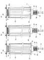
フィルタ10によってエアから分離されたヒューム等は、フィルタ10の外表面に付着し、フィルタ10の使用に伴い付着物は増加する。付着物がある程度の量に達した状態で、或いは、フィルタ10の使用時間が所定時間に達した段階で、集塵機1内へのエアの導入を停止し、フィルタ10から付着物を除去する処理を行う。以下、この処理について主に図3を用いて説明する。なお、図3は、説明の便宜上、フィルタ10や載置プレート20等の動きを誇張して図示している。また、図3では、上ケース及び下ケース部分のみを断面図で表している。 The fumes and the like separated from the air by the
フィルタ10から付着物を除去する処理に際しては、振動装置37を作動させる。これにより、振動装置37が底部に取り付けられている載置プレート20に振動が付与され、載置プレート20は上下に振動する。このとき、載置プレート20に固着されている上ケース34は、下ケース33に対して摺動しつつ上下に移動し、コイルバネ35は、上ケース34及び下ケース33の内部空間の高さに応じて伸縮する(図3(a),(b)参照)。 In the process of removing the deposits from the
載置プレート20の上には、フィルタ10が載置されているため、載置プレート20が上昇する際は、載置プレート20に押し上げられるように、フィルタ10は蛇腹管15を押し縮めながら上昇する(図3(b)参照)。フィルタ10は載置プレート20の上に単に載置されていただけであり、載置プレート20に固着されてはいないので、載置プレート20が下降するのに付随して下降することはなく、自重により下降する。そのため、振動装置37によって細かに振動させられる載置プレート20とは下降のタイミングがずれて、載置プレート20とフィルタ10の下端との間に空隙が生じる瞬間が存在する(図3(c)参照)。これにより、再び上昇した載置プレート20と、大きな衝撃を伴って衝突することとなり、フィルタ10は載置プレート20の上で跳ねるように上下動する。 Since the
すなわち、フィルタ10が載置プレート20に固着されている場合は、振動装置37による振動の付与に伴い、フィルタ10は載置プレート20と共に細かく振動するだけであるのに対し、本実施形態ではフィルタ10を載置プレート20に固着されていない構成としたため、大きな衝撃を伴って載置プレート20と衝突する。これにより、フィルタ10に付着した付着物を、効率良く離脱させることができる。 That is, when the
なお、載置プレート20の板体21は縁部23を有しているため、このようにフィルタ10が跳ねるように大きく上下動しても、フィルタ10が載置プレート20から外れることがない。また、載置プレート20の板体21には多数の貫通孔部が穿設されているため、フィルタ10から離脱した付着物は、貫通孔部を介してフィルタ室52の底面に落下し、ホッパ75の傾斜面に沿って滑り落ちて廃棄口66の上に堆積する。 In addition, since the
そして、載置プレート20は、コイルバネ35を介してフィルタ室52の底面52bに支持されているため、フィルタ10と大きな衝撃で衝突しても、その衝撃はケーシング50を介して集塵機1の他の部分に伝わりにくい。つまり、コイルバネ35は、載置プレート20の上下動を許容する構成であると共に、載置プレート20に作用する衝撃の他の部分への伝導を抑制している。 Since the mounting
また、フィルタ10は、蛇腹管15を介してフィルタ室52の天面52aに支持されているため、載置プレート20と大きな衝撃で衝突しても、その衝撃はケーシング50を介して集塵機1の他の部分に伝わりにくい。つまり、蛇腹管15は、フィルタ10の内部空間をバッファ室53と連通させる構成であり、且つ、フィルタ10の上下動を許容する構成であると共に、フィルタ10に作用する衝撃の他の部分への伝導を抑制している。 Further, since the
以上のように、本実施形態の集塵機1によれば、フィルタ10に下方から載置プレート20を衝突させ、衝撃を与えることにより、フィルタ10から付着物を効率良く除去することができる。そして、フィルタ10を上下動させることにより、フィルタ10全体に衝撃を与える構成であるため、局部的にフィルタ10に突片を接触させていた従来技術とは異なり、フィルタ10の損傷を低減して、付着物を除去することができる。特に、本実施形態では、載置プレート20に衝突するフィルタ10の下端には、フィルタ10を保護するキャップ11が嵌め込まれているため、フィルタ10がより損傷しにくいものとなっている。 As described above, according to the
また、載置プレート20はコイルバネ35によって上下動自在にフィルタ室52の底面52bに支持されており、フィルタ10は蛇腹管15によって上下動自在にフィルタ室52の天面に吊下げ支持されているため、フィルタ10と載置プレート20とが大きな衝撃で衝突しても、その衝撃がケーシング50を介して集塵機1の他の部分に伝わりにくいものとなっている。 The mounting
以上、本発明について好適な実施形態を挙げて説明したが、本発明は上記の実施形態に限定されるものではなく、本発明の要旨を逸脱しない範囲において、種々の改良及び設計の変更が可能である。 Although the present invention has been described with reference to the preferred embodiments, the present invention is not limited to the above-described embodiments, and various improvements and design changes can be made without departing from the scope of the present invention. It is.
例えば、上記の実施形態では、9つのフィルタ10が3個×3列に設けられ、一つの載置プレート20に3個(一列)のフィルタ10が載置される場合を例示したが、フィルタの個数や載置プレートの個数との関係は、これに限定されるものではない。 For example, in the above embodiment, nine
また、上記では、レーザ加工、アーク溶接、プラズマ加工等により生じたヒュームを含むエアをフィルタ10で濾過する集塵機1を例示したが、これに限定されず、一般粉塵や金属粉末などの粗粉塵を含むエアを処理する集塵機に、本発明を適用することができる。 Moreover, although the
1 集塵機
10 フィルタ
15 蛇腹管(伸縮部材)
20 載置プレート
33 下ケース
34 上ケース
35 コイルバネ
37 振動装置
52 フィルタ室
52a 天面(フィルタ室の天面)
52b 底面(フィルタ室の底面)1
20
52b Bottom (bottom of filter chamber)
Claims (3)
Translated fromJapaneseフィルタ室の底面にコイルバネを介して上下動自在に支持されており、前記フィルタを載置している載置プレートと、
該載置プレートに上下振動を付与する振動装置と、を具備しており、
前記フィルタは、前記載置プレートに固着されることなく載置されていることにより、前記載置プレートの上下振動に伴い、前記載置プレートとの間に空隙を生じ、前記載置プレート上で跳ねるように上下動し前記載置プレートに衝突するものである
ことを特徴とする集塵機。A cylindrical filter that is suspended and supported on the top surface of the filter chamber via an elastic member so as to freely move up and down;
A bottom plate of the filter chamber is supported through a coil spring so as to be movable up and down, and a mounting plate on which the filter is mounted;
A vibration device for impartingvertical vibration to the placing locationplate,which comprises a,
Since the filter is mounted without being fixed to the mounting plate, a gap is formed between the filter and the mounting plate due to vertical vibration of the mounting plate. A dust collectorthat moves up and down so as to bounce and collides with the mounting plate .
ことを特徴とする請求項1に記載の集塵機。The dust collector according to claim 1, wherein the mounting plate has a plurality of through holes.
フィルタ室の底面にコイルバネを介して上下動自在に支持されており、前記フィルタを載置している載置プレートと、
該載置プレートに振動を付与する振動装置と、
有底筒状で上方に開口し、フィルタ室の底面に固定されている下ケースと、
有底筒状で下方に開口し、前記下ケースに摺動自在に嵌め合わされていると共に、底部が前記載置プレートに固着されている上ケースとを具備し、
前記コイルバネは、前記上ケース及び前記下ケースの内部空間に収容されている
ことを特徴とする集塵機。A cylindrical filter that is suspended and supported on the top surface of the filter chamber via an elastic member so as to freely move up and down;
A bottom plate of the filter chamber is supported through a coil spring so as to be movable up and down, and a mounting plate on which the filter is mounted;
A vibration device for applying vibration to the mounting plate;
A bottom case that opens upward in a cylindrical shape with a bottom, and is fixed to the bottom surface of the filter chamber;
Downwardly opening bottomed cylindrical, with is slidably fitted in the lower case, andimmediately Beithe upper case bottom is fixed to the placing plate,
The coil spring is tothat precipitator unit, characterized in that it is housed in the internal space of the upper case and the lower case.
Priority Applications (1)
| Application Number | Priority Date | Filing Date | Title |
|---|---|---|---|
| JP2013184802AJP6026978B2 (en) | 2013-09-06 | 2013-09-06 | Dust collector |
Applications Claiming Priority (1)
| Application Number | Priority Date | Filing Date | Title |
|---|---|---|---|
| JP2013184802AJP6026978B2 (en) | 2013-09-06 | 2013-09-06 | Dust collector |
Publications (2)
| Publication Number | Publication Date |
|---|---|
| JP2015051391A JP2015051391A (en) | 2015-03-19 |
| JP6026978B2true JP6026978B2 (en) | 2016-11-16 |
Family
ID=52700838
Family Applications (1)
| Application Number | Title | Priority Date | Filing Date |
|---|---|---|---|
| JP2013184802AActiveJP6026978B2 (en) | 2013-09-06 | 2013-09-06 | Dust collector |
Country Status (1)
| Country | Link |
|---|---|
| JP (1) | JP6026978B2 (en) |
Families Citing this family (6)
| Publication number | Priority date | Publication date | Assignee | Title |
|---|---|---|---|---|
| AR106558A1 (en)* | 2015-11-03 | 2018-01-24 | Spraying Systems Co | APPARATUS AND SPRAY DRYING METHOD |
| KR101681865B1 (en)* | 2016-03-30 | 2016-12-01 | 박정훈 | Free fraction filter device and the control method |
| WO2018051666A1 (en)* | 2016-09-15 | 2018-03-22 | ソニー株式会社 | Projection-type image display apparatus, filter device, control device, and control method |
| CN107398127A (en)* | 2017-09-13 | 2017-11-28 | 大唐珲春发电厂 | Compressed air purifying filter |
| CN109458812A (en)* | 2018-11-25 | 2019-03-12 | 江苏普杰环保科技有限公司 | A kind of granule materials drying dust pelletizing system |
| JP7633663B2 (en)* | 2021-06-02 | 2025-02-20 | 株式会社エーエス | Classifiers and Classifier Groups |
Family Cites Families (3)
| Publication number | Priority date | Publication date | Assignee | Title |
|---|---|---|---|---|
| JPS5133360A (en)* | 1974-09-14 | 1976-03-22 | Kyuji Kobayashi | Shujinyofuirutaanomezumarinoboshi oyobi jokyosochi |
| JP3843401B2 (en)* | 1996-12-07 | 2006-11-08 | 前島 文夫 | Incinerator and incinerator for assembly |
| JP2005313041A (en)* | 2004-04-27 | 2005-11-10 | Furukawa Co Ltd | Dust collector |
- 2013
- 2013-09-06JPJP2013184802Apatent/JP6026978B2/enactiveActive
Also Published As
| Publication number | Publication date |
|---|---|
| JP2015051391A (en) | 2015-03-19 |
Similar Documents
| Publication | Publication Date | Title |
|---|---|---|
| JP6026978B2 (en) | Dust collector | |
| CN202724905U (en) | Bag-type dust collector | |
| JP6384918B2 (en) | Dust collector | |
| CN107511005A (en) | Filter bag dust removal equipment | |
| JP2012217976A (en) | Cleaning device of dust collection body | |
| KR20170025522A (en) | Dust cleaning apparatus | |
| CN102784526B (en) | Bag dust remover | |
| KR101899461B1 (en) | The sand blaster for wood with dust removal equipment | |
| CN201693458U (en) | Grinder dust collector | |
| CN203777834U (en) | Backflushing cloth-bag pulse dust removal device | |
| CN103282096B (en) | Dust arrester | |
| CN108479216B (en) | Stepping air suction ash removal dust remover | |
| JP5776632B2 (en) | Air filter regeneration method and air filter regeneration device | |
| CN113573793B (en) | Cleaning device and cleaning method for dust collector | |
| US6280491B1 (en) | Cartridge filter | |
| KR20130137921A (en) | Dust collector | |
| CN211913075U (en) | Bag-type dust collector | |
| JP2016087774A (en) | Dust collector | |
| CN219167955U (en) | Dust removing device | |
| JP3214995U (en) | Dust collector | |
| CN117679858A (en) | Bag type pulse dust collector | |
| CN202724897U (en) | Mechanical vibration bag type dust collector | |
| KR200485512Y1 (en) | Movable-type dust collector for removing of dust from electric transformer of railway vehicles. | |
| KR20140124658A (en) | Filtering device and the vacuum cleaner having it | |
| JP3153489U (en) | Dust collector |
Legal Events
| Date | Code | Title | Description |
|---|---|---|---|
| A621 | Written request for application examination | Free format text:JAPANESE INTERMEDIATE CODE: A621 Effective date:20150423 | |
| A977 | Report on retrieval | Free format text:JAPANESE INTERMEDIATE CODE: A971007 Effective date:20160304 | |
| A131 | Notification of reasons for refusal | Free format text:JAPANESE INTERMEDIATE CODE: A131 Effective date:20160315 | |
| A521 | Request for written amendment filed | Free format text:JAPANESE INTERMEDIATE CODE: A523 Effective date:20160509 Free format text:JAPANESE INTERMEDIATE CODE: A821 Effective date:20160509 | |
| TRDD | Decision of grant or rejection written | ||
| A01 | Written decision to grant a patent or to grant a registration (utility model) | Free format text:JAPANESE INTERMEDIATE CODE: A01 Effective date:20161004 | |
| A61 | First payment of annual fees (during grant procedure) | Free format text:JAPANESE INTERMEDIATE CODE: A61 Effective date:20161013 | |
| R150 | Certificate of patent or registration of utility model | Ref document number:6026978 Country of ref document:JP Free format text:JAPANESE INTERMEDIATE CODE: R150 | |
| R250 | Receipt of annual fees | Free format text:JAPANESE INTERMEDIATE CODE: R250 | |
| R250 | Receipt of annual fees | Free format text:JAPANESE INTERMEDIATE CODE: R250 | |
| R250 | Receipt of annual fees | Free format text:JAPANESE INTERMEDIATE CODE: R250 |