JP6024446B2 - Impact tools - Google Patents
Impact toolsDownload PDFInfo
- Publication number
- JP6024446B2 JP6024446B2JP2012280363AJP2012280363AJP6024446B2JP 6024446 B2JP6024446 B2JP 6024446B2JP 2012280363 AJP2012280363 AJP 2012280363AJP 2012280363 AJP2012280363 AJP 2012280363AJP 6024446 B2JP6024446 B2JP 6024446B2
- Authority
- JP
- Japan
- Prior art keywords
- duty ratio
- motor
- current
- hammer
- impact tool
- Prior art date
- Legal status (The legal status is an assumption and is not a legal conclusion. Google has not performed a legal analysis and makes no representation as to the accuracy of the status listed.)
- Active
Links
Images


Classifications
- B—PERFORMING OPERATIONS; TRANSPORTING
- B25—HAND TOOLS; PORTABLE POWER-DRIVEN TOOLS; MANIPULATORS
- B25B—TOOLS OR BENCH DEVICES NOT OTHERWISE PROVIDED FOR, FOR FASTENING, CONNECTING, DISENGAGING OR HOLDING
- B25B21/00—Portable power-driven screw or nut setting or loosening tools; Attachments for drilling apparatus serving the same purpose
- B25B21/02—Portable power-driven screw or nut setting or loosening tools; Attachments for drilling apparatus serving the same purpose with means for imparting impact to screwdriver blade or nut socket
- B25B21/026—Impact clutches
- B—PERFORMING OPERATIONS; TRANSPORTING
- B25—HAND TOOLS; PORTABLE POWER-DRIVEN TOOLS; MANIPULATORS
- B25B—TOOLS OR BENCH DEVICES NOT OTHERWISE PROVIDED FOR, FOR FASTENING, CONNECTING, DISENGAGING OR HOLDING
- B25B23/00—Details of, or accessories for, spanners, wrenches, screwdrivers
- B25B23/14—Arrangement of torque limiters or torque indicators in wrenches or screwdrivers
- B25B23/147—Arrangement of torque limiters or torque indicators in wrenches or screwdrivers specially adapted for electrically operated wrenches or screwdrivers
- B25B23/1475—Arrangement of torque limiters or torque indicators in wrenches or screwdrivers specially adapted for electrically operated wrenches or screwdrivers for impact wrenches or screwdrivers
Landscapes
- Engineering & Computer Science (AREA)
- Mechanical Engineering (AREA)
- Portable Power Tools In General (AREA)
- Details Of Spanners, Wrenches, And Screw Drivers And Accessories (AREA)
Description
Translated fromJapanese本発明はインパクト工具に関し、特に、駆動源として用いられるモータの制御方法を改良したインパクト工具に関する。 The present invention relates to an impact tool, and more particularly, to an impact tool having an improved control method for a motor used as a drive source.
手持ち式のインパクト工具、特にバッテリに蓄電された電気エネルギーにて駆動するコードレスタイプのインパクト工具が広く用いられている。ドリルやドライバ等の先端工具をモータによって回転駆動して所要の作業を行うインパクト工具においては、例えば特許文献1に開示されているように、バッテリを用いてブラシレスDCモータを駆動する。ブラシレスDCモータは、ブラシ(整流用刷子)の無いDC(直流)モータであり、コイル(巻線)をロータ側に、永久磁石をステータ側に用い、インバータで駆動された電力を所定のコイルへ順次通電することによりロータを回転させる。ブラシレスモータはブラシ付きモータに比べて高効率であり、充電可能な二次電池を使用しつつ高い出力を得ることが可能となる。また、モータの回転駆動のためのスイッチング素子を搭載した回路を有するので、電子制御により高度なモータの回転制御が容易となる。 Hand-held impact tools, particularly cordless impact tools that are driven by electrical energy stored in a battery, are widely used. In an impact tool that performs a required operation by rotating a tip tool such as a drill or a driver with a motor, a brushless DC motor is driven using a battery, as disclosed in, for example,
ブラシレスDCモータは、永久磁石を備えたロータ(回転子)と、3相巻線等の複数相の電機子巻線(固定子巻線)を備えたステータ(固定子)を含み、ロータの永久磁石の磁力を検出してロータ位置を検出する複数のホールICより構成された位置検出素子と、電池パック等から供給される直流電圧をFET(電界効果トランジスタ)やIGBT(絶縁ゲート・バイポーラ・トランジスタ)等の半導体スイッチング素子を用いてスイッチングして各相の固定子巻線への通電を切換えてロータを駆動するインバータ回路と共に実装される。複数の位置検出素子は複数相の電機子巻線に対応しており、各位置検出素子によるロータの位置検出結果に基づいて各相の電機子巻線の通電タイミングを設定する。 The brushless DC motor includes a rotor (rotor) having permanent magnets and a stator (stator) having a plurality of armature windings (stator windings) such as three-phase windings. A position detection element composed of a plurality of Hall ICs that detect the magnetic position of the magnet to detect the rotor position, and a DC voltage supplied from a battery pack or the like is applied to an FET (field effect transistor) or an IGBT (insulated gate bipolar transistor). It is mounted with an inverter circuit that drives the rotor by switching using a semiconductor switching element such as) to switch the energization to the stator windings of each phase. The plurality of position detection elements correspond to the armature windings of a plurality of phases, and the energization timing of the armature windings of each phase is set based on the rotor position detection result by each position detection element.
図12は従来のインパクト工具におけるモータ電流、PWM駆動信号のデューティ比、締付トルクの関係を示すグラフである。ここで時刻t0にて作業者がトリガを引くことによりモータの回転が開始させてネジ等の締め付け作業を行う。この際のPWM駆動信号のデューティ比202は100%である。図12(3)が締め付けトルク値(N/m)であり、時間が経過すると共に締付トルク値203が徐々に上昇する。そして締め付け部材からの反力が所定のトルク値以上になるとアンビルに対してハンマが後退することによりアンビルとハンマの係合関係が外れ、その係合関係が外れるとハンマは前方に移動しながら回転することにより時刻t1においてアンビルに衝突し、アンビルに対して強い締め付けトルクを発生させる。この際のモータを駆動するインバータ回路に供給されるPWMデューティ比は図12(2)のデューティ比202に示すように100%のまま、つまりフルパワー状態である。このようなモータの駆動制御におけるモータ電流を示すのが図12(1)のモータ電流201である。モータ電流201はハンマの後退に応じて矢印201aのように急激に上昇して係合状態が外れる手前にてピーク電流(矢印201b)に到達し、係合状態が外れると急低下して矢印201cにて打撃を行うことにより再び係合状態となるためモータ電流201は再び増加し始める。FIG. 12 is a graph showing the relationship between the motor current, the duty ratio of the PWM drive signal, and the tightening torque in a conventional impact tool. Here, when the operator pulls the trigger at time t0, the rotation of the motor is started to perform the tightening operation of the screw or the like. The
ここで図13を用いてインパクト工具におけるハンマとアンビルを含む打撃部の動きと、モータ電流の増減関係を説明する。スピンドルに設けられるカム機構の作用により前後退をするハンマ210は、アンビル220からの反力が少ないうちは当接状態を保ったまま回転するが、反力が大きくなるとハンマ210はカム機構のスピンドルカム溝に沿ってスプリングを圧縮しながら矢印231のようにモータ側(図13では上側)へと後退を始める(図13(A))。そして、ハンマ210の後退動によってハンマ210の凸部がアンビル220を乗り越えて両者の係合が解除されると、ハンマ210は、スピンドルの回転力により矢印232のように回転しながら、スプリングに蓄積されていた弾性エネルギーとカム機構の作用によって矢印233のように前方に急速に加速されつつ前方へ移動する(図13(B))。そしてハンマ210の凸部がアンビル220に衝突することにより再び係合して矢印234のように一体に回転し始める(図13(C))。このとき、強力な回転打撃力がアンビル220に加えられる。この際のモータ電流240(単位A)を示すのが下側の曲線であり、カム機構のスピンドルカム溝に沿ってスプリングを圧縮しながら矢印231のように後方に移動するときにモータ電流240が矢印240aのようにピークに達する。そして(B)のようにハンマ210とアンビル220の係合状態が外れると、ハンマ210には反力が作用しないため負荷が軽くなりモータ電流201は矢印240bのように低下する。そして、矢印240cようにモータ電流240がほぼ低下した付近で打撃が行われる。尚、図12で示した201bから201cは、図13の矢印240aから240cの部分に相当する。 Here, the movement of the striking part including the hammer and the anvil in the impact tool and the increase / decrease relationship of the motor current will be described with reference to FIG. The
再び図12に戻る。図12の時刻t1、矢印201cの時点において打撃が行われた場合、ねじ締め部材が短いネジの場合は、図12(3)の矢印203aのように1回目の打撃でいきなり設定トルク値TNを超えてしまうことがある。しかしながら、設定トルク値に到達しても自動停止しない電動工具の場合には、作業者がトリガを離す前にさらに数回打撃してしまうことがありうる。例えば、図12(3)の例では時刻t2にて2回目の打撃が行われ、この際のモータ電流は201c〜201fのように増減する。この際、場合によってはネジ山を壊してしまったり、ネジ頭をねじ切ってしまったりする恐れがある。Returning again to FIG. When the impact is performed at time t1 in FIG. 12 and at the time of the
ところで、近年インパクト工具の出力の増加化が図られており、工具サイズを小さくしつつ高い回転速度、高い締め付けトルクを得ることができるようになってきた。しかしながら、高い締め付けトルクを実現することはねじ締め作業等において最初の打撃の時に必要以上に強い打撃を与えてしまうことになり、ネジを痛めてしまう恐れが一層高くなる。この対策としては衝撃を小さくしようとしてモータの回転速度を低下させた状態で締め付けを行うことが考えられるが、そうすると締め付け全体に要する時間が長くなってしまい作業効率の低下につながる。 Incidentally, in recent years, the output of impact tools has been increased, and it has become possible to obtain a high rotational speed and a high tightening torque while reducing the tool size. However, realization of a high tightening torque will give a stronger impact than necessary at the time of the first impact in a screw tightening operation or the like, and the risk of damaging the screw is further increased. As a countermeasure, it is conceivable to perform tightening while reducing the rotational speed of the motor in order to reduce the impact. However, if this is done, the time required for the entire tightening becomes longer, leading to a reduction in work efficiency.
本発明は上記背景に鑑みてなされたもので、その目的とするところは、小さいネジやなべネジ等であっても精度良く高速に締め付けることができるインパクト工具を提供することにある。 The present invention has been made in view of the above background, and an object of the present invention is to provide an impact tool that can be tightened with high accuracy and high speed even with a small screw or a pan screw.
本発明の別の目的は、締め付け効率の低下することなく打撃の際のネジ頭の破損を防止することができるインパクト工具を提供することにある。 Another object of the present invention is to provide an impact tool that can prevent the screw head from being damaged at the time of impact without lowering the tightening efficiency.
本発明のさらに別の目的は、下穴機能付きのセルフドリリングねじやタッピングビスを効率良く締め付けることができるインパクト工具を提供することにある。 Still another object of the present invention is to provide an impact tool capable of efficiently tightening a self-drilling screw having a pilot hole function or a tapping screw.
本願において開示される発明のうち、代表的なものの特徴を説明すれば、次の通りである。
本発明の一つの特徴によれば、モータと、半導体スイッチング素子を用いてモータへ供給する駆動電力を制御する制御手段と、モータの回転力により先端工具を連続的に又は断続的に駆動するものであってハンマとアンビルを含む打撃機構を有するインパクト工具において、制御手段はトリガが引かれたら半導体スイッチング素子を高デューティ比で駆動し、ハンマによるアンビルの最初の打撃が行われる前にデューティ比を低くして低デューティ比にて打撃を行うようにモータを駆動する。デューティ比の切り替えは、ハンマとアンビルとの係合が外れる前に行われ、特に好ましくはハンマが後退し始める直前、例えば打撃の行われる1/4回転以上1回転未満前に行われると良い。ここで高デューティ比と低デューティ比は、トリガをフルに引いた場合の上限値の設定であって、トリガの引き具合によってデューティ比は、0より高デューティ比の範囲内で、もしくは、0より低デューティ比の範囲内で制御手段により設定される。Of the inventions disclosed in the present application, typical features will be described as follows.
According to one aspect of the present invention, the motor, the control means for controlling the drive power supplied to the motor using the semiconductor switching element, and the tip tool is driven continuously or intermittently by the rotational force of the motor. In an impact tool having a striking mechanism including a hammer and an anvil, the control means drives the semiconductor switching element at a high duty ratio when the trigger is pulled, and sets the duty ratio before the first striking of the anvil by the hammer. The motor is driven so as to make a hit with a low duty ratio at a low value. Switching of the duty ratio is performed before the engagement between the hammer and the anvil is released, and particularly preferably, it is performed immediately before the hammer starts to retreat, for example, a quarter rotation or more and less than one rotation before the hammer is performed. Here, the high duty ratio and the low duty ratio are setting of the upper limit value when the trigger is fully pulled, and the duty ratio is within a range of the duty ratio higher than 0 or from 0 depending on how the trigger is pulled. It is set by the control means within the range of the low duty ratio.
本発明の他の特徴によれば、モータまたは半導体スイッチング素子に流れる電流値を検出する電流検出手段を設け、制御手段は電流値が第1の閾値を最初に超えた時点で高デューティ比から低デューティ比に切り替えるように制御する。モータはブラシレスDCモータとするのが好ましく、半導体スイッチング素子を複数用いたインバータ回路によりブラシレスモータを駆動すると良い。高デューティ比は80〜100%の範囲で設定され、低デューティ比は設定された高デューティ比の60%以下の値に設定されると良い。締め付け完了によるモータの回転停止は、作業者がトリガを戻すことで行っても良いし、制御手段によって電流値が第1の閾値よりも高い第2の閾値を超えたことを検出した時点でモータの駆動を自動的に停止させても良い。According to another feature of the invention, there is provided a current detecting means for detecting a current value flowing through the motor or the semiconductor switching element, and the controlmeans reduces the high duty ratio from the high duty ratio when the current value first exceeds the first threshold value. Control to switch to the duty ratio. The motor is preferably a brushless DC motor, and the brushless motor may be driven by an inverter circuit using a plurality of semiconductor switching elements. The high duty ratio is set in a range of 80 to 100%, and the low duty ratio is preferably set to a value that is 60% or less of the set high duty ratio. Stopping the rotation of the motor upon completion of tightening may be performed by the operator returning the trigger, or when the controlmeans detects that the current value has exceeded a second threshold valuehigher than the first threshold value. May be automatically stopped.
本発明のさらに他の特徴によれば、低デューティ比に切り替えた後に、電流検出手段により検出される電流値が第1の閾値以下の場合に、低デューティ比を所定の比率で連続して増加させ(但し、増加後のデューティ比は高デューティ比を越えない)、(b)電流検出手段により検出される電流値が第1の閾値を再び超えた場合は、デューティ比を低デューティ比に再び戻し、以降、(a)と(b)の手順を繰り返すようにした。 According to still another feature of the present invention, the low duty ratio is continuously increased at a predetermined ratio when the current value detected by the current detection means is equal to or lower than the first threshold after switching to the low duty ratio. (However, the increased duty ratio does not exceed the high duty ratio.) (B) When the current value detected by the current detection means exceeds the first threshold value again, the duty ratio is changed to the low duty ratio again. After that, the procedures of (a) and (b) were repeated.
本発明のさらに他の特徴によれば、低デューティ比に切り替えた後に、電流検出手段により検出される電流値が第1の閾値よりも十分低い第3の閾値以下になった場合に、低デューティ比を高いデューティ比に戻し、ハンマによるアンビルの次の打撃が行われる前に低デューティ比に切り替えて以降の打撃を行うようにモータを駆動する。 According to still another aspect of the present invention, when the current value detected by the current detection means becomes equal to or lower than a third threshold value that is sufficiently lower than the first threshold value after switching to a low duty ratio, the low duty ratio is set. The ratio is returned to the high duty ratio, and the motor is driven so as to perform the subsequent hitting by switching to the low duty ratio before the next hitting of the anvil by the hammer.
請求項1の発明によれば、制御手段はトリガが引かれたら高デューティ比で駆動するものの、最初の打撃直前に低デューティ比に切り替えて以降の打撃を行うので、高出力モータを用いたインパクトドライバにて短いネジや下穴機能付きのセルフドリリングねじを用いる場合であっても、作業スピードを低減すること無く、ネジ頭やネジ溝を破損したり、被締付材側を痛めてしまうことを効果的に防止できる。この結果、高出力型モータを採用することができる上にモータの省電力化を図ることができ、さらにはインパクト工具の信頼性及び寿命を向上できる。
請求項2の発明によれば、デューティ比の切り替えは、ハンマとアンビルとの係合が外れる前に行われるので、打撃が行われるまでは最大速度にて締め付けを行い、打撃の際には確実にデューティ比を低減させて適切な打撃力にてインパクト打撃を行うことができる。通常、係合が外れた直後には電流が下がってしまい、その後にデューティを下げても既にハンマがスプリングの力で加速し始めており初回の打撃力がほとんど小さくならないが、請求項2の発明によれば係合が外れる前にデューティ比の切り替えを行うので、最初の打撃時には低デューティ比による打撃を行うことができる。
請求項3の発明によれば、デューティ比の切り替えは、ハンマが後退し始める前に行われるので、デューティ比の低減による締め付け速度の低下を防止することができる。ここでハンマが後退し始めてからデューティ比を下げようとすると、係合が外れるまでの時間が非常に短いため、十分にモータの速度が低下しない可能性があるが、請求項3の発明によれば早めにデューティ比を下げることでモータの速度を十分に低下させることができる。
請求項4の発明によれば、インバータ回路駆動のブラシレスモータを用いるので、デューティ比の制御によりきめ細かな締め付け制御を行うことができる。
請求項5の発明によれば、高デューティ比は80〜100%の範囲で設定され、低デューティ比は設定された高デューティ比の60%以下の値に設定されるので、締め付けトルク不足を生ずること無く規定のトルクにて確実に締め付け作業を完遂できる。According to the first aspect of the present invention, although the control means is driven at a high duty ratio when the trigger is pulled, the control means performs the subsequent impact by switching to the low duty ratio immediately before the first impact, so that the impact using the high output motor is achieved. Even when using a short screw or a self-drilling screw with a pilot hole function in a screwdriver, the screw head or groove may be damaged or the material to be tightened may be damaged without reducing the work speed. Can be effectively prevented. As a result, it is possible to employ a high-output motor, to save power in the motor, and to improve the reliability and life of the impact tool.
According to the invention of
According to the invention of
According to the invention of
According to the invention of
請求項6の発明によれば、制御手段は電流検出装置により検出された電流値が第1の閾値を最初に超えた時点で高デューティ比から低デューティ比に切り替えるので、特別な検出センサを別途準備することなく打撃の行われる直前にデューティ比を切り替えることができる。
請求項7の発明によれば、制御手段は電流値が第2の閾値を超えた時点でモータの駆動を停止させるので、締め付け不足又は締め付け過多を防止できる。
請求項8の発明によれば、低デューティ比に落とした後に、所定の比率にて徐々にデューティ比を上昇させるので、最初に低デューティ比に落とした後には、モータ電流のピーク値を追跡すること無く簡単な処理にてデューティ比の変動制御を行うことができ、低い処理能力のマイコンを用いた制御手段であっても本発明の処理を実現できる。
請求項9の発明によれば、低デューティ比に切り替えた後に電流値が第1の閾値よりも十分低い第3の閾値以下になった場合に再び高デューティ比に戻すので、外乱等の何らかの要因により電流値が一時的に上昇した場合であっても正常に締め付け動作を完了させることができ、締め付け不足の発生を防止できる。
According to the invention of
According to the seventh aspect of the present invention, the controlmeans stops driving the motor when the current value exceeds the second threshold value, so that insufficient tightening or excessive tightening can be prevented.
According to the eighth aspect of the invention, since the duty ratio is gradually increased at a predetermined ratio after being lowered to the low duty ratio, the peak value of the motor current is traced after the duty ratio is first lowered to the low duty ratio. Therefore, the duty ratio fluctuation control can be performed with simple processing, and the processing of the present invention can be realized even with controlmeans using a microcomputer with low processing capability.
According to the ninth aspect of the present invention, when the current value falls below the third threshold value sufficiently lower than the first threshold value after switching to the low duty ratio, the high duty ratio is restored again. Thus, even when the current value temporarily increases, the tightening operation can be completed normally, and the occurrence of insufficient tightening can be prevented.
本発明の上記及び他の目的ならびに新規な特徴は、以下の明細書の記載及び図面から明らかになるであろう。 The above and other objects and novel features of the present invention will become apparent from the following description and drawings.
以下、本発明の実施例を図面に基づいて説明する。尚、以下の説明において、上下、前後の方向は、図1の矢印に示した方向として説明する。 Embodiments of the present invention will be described below with reference to the drawings. In the following description, the vertical and forward / backward directions will be described as directions indicated by arrows in FIG.
図1は、本発明に係るインパクト工具1の内部構造を示す図である。インパクト工具1は、充電可能なバッテリ9を電源とし、モータ3を駆動源として回転打撃機構21を駆動し、出力軸であるアンビル30に回転力と打撃力を与え、スリーブ31の取付穴30aに保持されるドライバビット等の図示しない先端工具に回転打撃力を間欠的に伝達してネジ締めやボルト締め等の作業を行う。ブラシレスDC方式のモータ3は、側面視で略T字状の形状を成すハウジング2の筒状の胴体部2a内に収容される。モータ3の回転軸12は、ハウジング2の胴体部2aの中央部付近に設けられる軸受19aと後端側の軸受19bによって回転可能に保持され、モータ3の前方には、回転軸12と同軸に取り付けられモータ3と同期して回転するロータファン13が設けられ、モータ3の後方には、モータ3を駆動するためのインバータ回路基板4が配設される。ロータファン13によって起こされる空気流は、空気取入孔17a、17b及びインバータ回路基板4の周囲のハウジング部分に形成されたスロット(図示せず)からハウジング2の内部に取り込まれ、主にロータ3aとステータ3bの間を通過するように流れ、ロータファン13の後方から吸引されてロータファン13の径方向外側に流れ、ロータファン13の周囲のハウジング部分に形成された図示しないスロットからハウジング2の外部に排出される。インバータ回路基板4はモータ3の外形とほぼ同形の円形の両面基板であり、この基板上にはFET等の複数のスイッチング素子5や、ホールIC等の位置検出素子33が搭載される。 FIG. 1 is a diagram showing an internal structure of an
ロータ3aと軸受19aの間には、スリーブ14とロータファン13が回転軸12と同軸上に取り付けられる。ロータ3aは、マグネット15によって形成される磁路を形成するもので、例えば4つの平板状のスロットが形成された薄い金属板の積層により構成される。スリーブ14は、ロータファン13とロータ3aが空転せずに回るようにする接続部材で、例えばプラスチックによって形成される。スリーブ14の外周部には、必要に応じてバランス修正用溝(図示せず)を形成する。ロータファン13は、例えばプラスチックのモールドにより一体成形されるもので、後方の内周側から空気を吸引し、前方側の半径方向外側に排出する、いわば遠心ファンであり、回転軸12が貫通する貫通穴の周囲から放射状に延びる複数のブレードを有する。ロータ3aと軸受19bの間には、プラスチック製のスペーサ35が設けられる。スペーサ35の形状は略円筒形で、軸受19bとロータ3aとの間の間隔を設定する。この間隔はインバータ回路基板4(図1)を同軸上に配置するためと、スイッチング素子5を冷却する空気流の流路として必要とされる空間を形成するために必要とされるものである。 Between the
ハウジング2の胴体部2aから略直角に一体に延びるハンドル部2b内の上部にはスイッチトリガ(SWトリガ)6が配設され、スイッチトリガ6の下方にはスイッチ基板7が設けられる。スイッチトリガ6の上方には、モータ3の回転方向を切り替えるための正逆切替レバー10が設けられる。ハンドル部2b内の下部には、スイッチトリガ6の引き動作によって前記モータ3の速度を制御する機能を備えた制御回路基板8が収容され、この制御回路基板8は、バッテリ9とスイッチトリガ6に電気的に接続される。制御回路基板8は、信号線11bを介してインバータ回路基板4と接続される。ハンドル部2bの下方には、ニカド電池、リチウムイオン電池等を含んで構成されるバッテリ9が着脱可能に装着される。バッテリ9は例えばリチウムイオン電池等の複数本の二次電池をパック化したもので、バッテリ9を充電するときは、インパクト工具1からバッテリ9を取り外して、図示しない専用の充電器に装着することにより充電される。 A switch trigger (SW trigger) 6 is disposed in an upper portion of the
回転打撃機構21は、遊星歯車減速機構22とスピンドル27とハンマ24を備え、後端が軸受20、前端がメタル29により保持される。スイッチトリガ6が引かれてモータ3が起動されると、正逆切替レバー10で設定された方向にモータ3が回転を始め、その回転力は遊星歯車減速機構22によって減速されてスピンドル27に伝達され、スピンドル27が所定の速度で回転駆動される。ここで、スピンドル27とハンマ24とはカム機構によって連結され、このカム機構は、スピンドル27の外周面に形成されたV字状のスピンドルカム溝25と、ハンマ24の内周面に形成されたハンマカム溝28と、これらのカム溝25、28に係合するボール26によって構成される。 The
ハンマ24は、スプリング23によって常に前方に付勢されており、静止時にはボール26とカム溝25、28との係合によってアンビル30の端面とは隙間を隔てた位置にある。そして、ハンマ24とアンビル30の相対向する回転平面上の2箇所には図示しない凸部がそれぞれ対称的に形成されている。スピンドル27が回転駆動されると、その回転はカム機構を介してハンマ24に伝達され、ハンマ24が半回転しないうちにハンマ24の凸部がアンビル30の凸部に係合してアンビル30を回転させるが、そのときの係合反力によってスピンドル27とハンマ24との間に相対回転が生ずると、ハンマ24はカム機構のスピンドルカム溝25に沿ってスプリング23を圧縮しながらモータ3側へと後退を始める。 The
そして、ハンマ24の後退動によってハンマ24の凸部がアンビル30の凸部を乗り越えて両者の係合が解除されると、ハンマ24は、スピンドル27の回転力に加え、スプリング23に蓄積されていた弾性エネルギーとカム機構の作用によって回転方向及び前方に急速に加速されつつ、スプリング23の付勢力によって前方へ移動し、その凸部がアンビル30の凸部に再び係合して一体に回転し始める。このとき、強力な回転打撃力がアンビル30に加えられるため、アンビル30の取付穴30aに装着される図示しない先端工具を介してネジに回転打撃力が伝達される。以後、同様の動作が繰り返されて先端工具からネジに回転打撃力が間欠的に繰り返し伝達され、例えば、ネジが木材等の図示しない被締めつけ材にねじ込まれる。 When the protrusion of the
次に図2を用いて、本実施例に係るインバータ回路基板4を説明する。図2は、インバータ回路基板4を示す図であり、(1)はインパクト工具1の後側から見た背面図であり、(2)は側面から見た側面図である。インバータ回路基板4は、例えばガラエポ (ガラス繊維をエポキシ樹脂で固めたもの)で構成され、モータ3の外形とほぼ同形の略円形であり、中央にはスペーサ35を貫通させるための穴4aが形成される。インバータ回路基板4の周囲には、4つのねじ穴4bが形成され、このねじ穴4bを貫通するねじによって、インバータ回路基板4がステータ3bに固定される。インバータ回路基板4には、穴4aを囲むように6つのスイッチング素子5が取り付けられる。本実施例ではスイッチング素子5として薄型のFETを用いたが、通常サイズのFETであっても良い。 Next, the
スイッチング素子5は厚さが非常に薄いので、本実施例においては、基板上に寝かせた状態で、表面実装(SMT:Surface mount technology)によってスイッチング素子5をインバータ回路基板4に取り付ける。尚、図示していないが、インバータ回路基板4の6つのスイッチング素子5全体を覆うように、シリコンなどの樹脂をコーティングすることが望ましい。インバータ回路基板4は両面基板となっており、その前面側には3つの位置検出素子33(図2(2)では2つだけ図示)と、サーミスタ34等の電子素子が搭載される。インバータ回路基板4は、モータ3と同形の円よりも下方にやや突出する形状であり、その突出した部分に複数の貫通穴4dが形成され、前面側から信号線11bが貫通されて後面側においてはんだ付け38bにより固定される。同様に電源線11aも前面側からインバータ回路基板4の貫通穴4cを貫通されて、後面側においてはんだ付け38aにより固定される。尚、信号線11bと電源線11aのインバータ回路基板4への固定は、基板上に固定されるコネクタを介しても良い。 Since the
次に、図3を用いてモータ3の駆動制御系の構成と作用を説明する。図3はモータの駆動制御系の構成を示すブロック図であり、本実施例では、モータ3は3相のブラシレスDCモータで構成される。 Next, the configuration and operation of the drive control system of the
モータ3は、いわゆるインナーロータ型で、一対のN極およびS極を含むマグネット15(永久磁石)を埋め込んで構成されたロータ3aと、ロータ3aの回転位置を検出するために60°毎に配置された3つの位置検出素子33と、位置検出素子33からの位置検出信号に基づいて電気角120°の電流の通電区間に制御されるスター結線された3相巻線U、V、Wからなるステータ3bを含んで構成される。なお、本実施例では、ロータ3aの位置検出は、ホールIC等の位置検出素子33を用いて電磁結合的に行っているが、電機子巻線の誘起起電圧(逆起電力)を、フィルタを通して論理信号として取出すことによってロータ3aの位置を検出するセンサレス方式を採用することもできる。 The
インバータ回路基板4に搭載されるインバータ回路は、3相ブリッジ形式に接続された6個のFET(以下、単に「トランジスタ」という。)Q1〜Q6と、フライホイールダイオード(図示なし)から構成され、インバータ回路基板4に搭載される。温度検出用素子(サーミスタ)34は、インバータ回路基板4上のトランジスタに近接する位置に固定される。ブリッジ接続された6個のトランジスタQ1〜Q6の各ゲートは制御信号出力回路48に接続され、また、6個のトランジスタQ1〜Q6のソースまたはドレインはスター結線された電機子巻線U、VおよびWに接続される。これによって、6個のトランジスタQ1〜Q6は、制御信号出力回路48から出力されたスイッチング素子駆動信号によってスイッチング動作を行い、インバータ回路に印加されるバッテリ9の直流電圧を、3相(U相、V相、W相)交流電圧Vu、Vv、Vwとして、電機子巻線U、V、Wへ電力を供給する。 The inverter circuit mounted on the
制御回路基板8には、演算部40、電流検出回路41、電圧検出回路42、印加電圧設定回路43、回転方向設定回路44、回転子位置検出回路45、回転数検出回路46、温度検出回路47、及び制御信号出力回路48が搭載される。演算部40は、図示されていないが、処理プログラムとデータに基づいて駆動信号を出力するためのCPU、後述するフローチャートに相当するプログラムや制御データを記憶するためのROM、データを一時記憶するためのRAM、タイマ等を含むマイコンによって構成される。電流検出回路41はシャント抵抗36の両端電圧を測定することによりモータ3に流れる電流を検出する電圧検出手段であって、検出電流は演算部40に入力される。電圧検出回路42はバッテリ9のバッテリ電圧を検出するための回路であり、検出された検出電圧は演算部40に入力される。 The
印加電圧設定回路43は、スイッチトリガ6の移動ストロークに応答してモータ3の印加電圧、すなわちPWM信号のデューティ比を設定するための回路である。回転方向設定回路44は、モータの正逆切替レバー10による正方向回転または逆方向回転の操作を検出してモータ3の回転方向を設定するための回路である。回転子位置検出回路45は、3つの位置検出素子33の出力信号に基づいてロータ3aとステータ3bの電機子巻線U、V、Wとの関係位置を検出するための回路である。回転数検出回路46は、単位時間内にカウントされる回転子位置検出回路45からの検出信号の数に基づいてモータの回転数を検出する回路である。制御信号出力回路48は、演算部40からの出力に基づいてトランジスタQ1〜Q6にPWM信号を供給する。PWM信号のパルス幅の制御によって各電機子巻線U、V、Wへ供給する電力を調整して設定した回転方向へのモータ3の回転数を制御することができる。 The applied
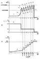
次に、図4のグラフを用いて本実施例のインパクト工具におけるモータ電流、PWM駆動信号のデューティ比、締付トルクの関係を説明する。(1)〜(3)の各グラフは横軸が時間(ミリ秒)であり、互いの横軸を合わせて図示している。本実施例においては、インパクト工具1を用いて、短いねじ又は短いセルフドリリングねじを締め付ける場合の例であって、時刻t0において作業者がスイッチトリガ6を引くことによりモータ3が始動し、それによってアンビル30に所定の締付トルク53が発生する。ネジが着座すると締付材から受けるトルクの反力が増大し、ハンマ24の後退動によってハンマ24の凸部がアンビル30の凸部を乗り越えて両者の係合が解除される。この結果、ハンマ24はスプリング23に蓄積されていた弾性エネルギーとカム機構の作用によって時刻t2においてアンビル30の凸部を打撃する。この最初の打撃に至るまでのモータ電流51の変動を示すのが図4(1)であり、矢印51bから51dまでのモータ電流51の変動が図13のモータ電流240の変動に相当する。ここで、ハンマ24の打撃の前でハンマ24が後ろに後退する時のモータ電流51が最大となり(矢印51c)、モータ3にかかる負荷が最大となり電流値がピークに達する。Next, the relationship among the motor current, the duty ratio of the PWM drive signal, and the tightening torque in the impact tool of this embodiment will be described with reference to the graph of FIG. In the graphs (1) to (3), the horizontal axis represents time (milliseconds), and the horizontal axes are shown together. In this embodiment, the
本実施例では、このモータ電流51が所定の閾値(第1の閾値)たる電流閾値I1を越えたら図4(2)の時刻t1のようにPWM(Pulse Width Modulation)制御のデューティ比52の制限値を100%から40%に低下させる。この電流閾値I1は、高めに設定されていたデューティ比を低めに切り替えるタイミングを設定するための作業判別用の閾値である。このようにデューティ比52を100%から40%に低下させることによりモータ電流51の推移は矢印51bから矢印51cに至るようになる。尚、仮に時刻t1においてデューティ比52を落とさずに100%のままとすると、モータ電流は点線54のように急上昇し、1回目の打撃(時刻t2)直後にモータ3を停止させるための電流閾値(第2の閾値)ISTOPを越える恐れがある。この場合締め付けられるねじに対して急激に打撃をしてしまう結果、ねじ頭を痛める恐れがある。本実施例では、1回目の打撃が起こる直前である時刻t1の時点でデューティ比52を100%から40%に低下させるため、打撃前はモータのフルパワーによる素早い締め付けを行い、打撃の所定回転前(本実施例では1/4回転〜1回転前であって例えば1/2回転程度前)においてデューティ比を落として以降の打撃を行うようにした。In the present embodiment, when the motor current 51 exceeds a current threshold value I1 that is a predetermined threshold value (first threshold value), a
このように時刻t1においてデューティ比を40%に低下させるため、以降の打撃を適正な強さにて行うことができ、その際のモータ電流51はハンマ24(図1参照)の回転位置、前後位置に応じて矢印51dから51hのように変動しながら複数回の打撃が行なわれる。この際の締付トルク53は1回目の打撃(時刻t2)、2回目の打撃(時刻t3)が行われるにつれて矢印53a、53bのように徐々に増大し、3回目の打撃(時刻t4)が行われた後には矢印53cのように締め付け設定トルク値Tnを越えるため締め付けが完了する。本実施例では締め付け完了をモータ電流51の監視により演算部40(図3参照)が行うように構成した。そのためモータ3の回転を停止させる判別の電流閾値ISTOPを設定し、矢印51iのように時刻t5においてモータ電流51が電流閾値ISTOPを越えたことを検出したら、演算部40はインバータ回路に供給する制御信号を停止させてモータ3の回転を停止する。本実施例の制御によれば、たとえ短いネジであったとしてもインパクト打撃を強く行って1回で終了させるのでは無く、適正な打撃で時刻t2、t3、t4のように複数回に分けて行うのでネジ頭を痛めること無く確実に締め付け作業を完了させることができる。To reduce this way the duty ratio at the time t1 to 40%, can be carried out subsequent to hit at a proper intensity, the motor current 51 during the rotation position of the hammer 24 (see FIG. 1), A plurality of hits are made while fluctuating as indicated by arrows 51d to 51h according to the front and rear positions. The tightening
次に図5に長いねじ又は長いセルフドリリングねじを締め付ける場合の、インパクト工具におけるモータ電流、PWM駆動信号のデューティ比、締付トルクの関係を説明する。演算部40において制御する制御方法は図4の場合と同じで有り、ネジの長さが長いために締め付け完了までに必要な打撃数が多くなるだけである。先ず、時刻t0にてモータ3の回転が開始されると、ねじの締め付け状況に応じてモータ電流61が上昇し、ネジの締め付けが所定の段階(例えば着座、セルフドリリングねじ、セルフタッピングビスにおいて下穴機能部の通過)になるとネジから受ける負荷が上昇するため、矢印61aのように急に上昇し、時刻t1にて電流閾値I1を越えるため、演算部40はPWMのデューティ比を100%から40%に低下させる。その後、ハンマ24が後退することにより矢印61cのように最大になった後にハンマ24とアンビルとの係合状態が外れるためモータ電流61が低下し、最も低下した付近(矢印61d)にて1回目の打撃が行われる。この際の締め付けトルク値は矢印63aのように上昇する。同様の打撃を時刻t3、t4、t5、t6と行い、その際のモータ電流は矢印61e〜61lのように増減する。この際のピーク電流は矢印61e、61g、61i、61k、61mとなるがそれらは停止判別電流閾値ISTOPを越えていない。その際の締付トルク値は、矢印63b、63c、63d、63eのように段階的に増大していく。そして時刻t7において6回目の打撃が行われると矢印61oに示すように時刻t8にて停止判別電流閾値ISTOPを越えるために演算部40はモータ3の回転を停止させる。このように6回目の打撃によって締付トルク値63は矢印63fのように設定トルク値Tnを越えるため締め付け動作が完了する。Next, FIG. 5 illustrates the relationship between the motor current, the duty ratio of the PWM drive signal, and the tightening torque in the impact tool when a long screw or a long self-drilling screw is tightened. The control method controlled in the
以上のように、本実施例では連続してデューティ比100%で打撃を行うのでは無く、1回目の打撃の前に低デューティ比40%に切り替えてから以降の打撃が行われるようにした。このように打撃は必ず低いデューティ比で行うようにしたので、初回の打撃でいきなり設定トルク値TNを越えること無く、複数回の打撃により確実に締め付けを完了させることができる。尚、本実施例では高デューティ比と低デューティ比の組み合わせを100%と40%としたが、高デューティ比は80〜100%の範囲で設定して、低デューティ比は設定された高デューティ比の60%以下の値にするように、例えば90%、30%というようにその他のデューティ比の組み合わせとなるように設定しても良い。As described above, in this embodiment, instead of continuously striking at a duty ratio of 100%, the subsequent striking is performed after switching to a low duty ratio of 40% before the first striking. In this way, the impact is always performed with a low duty ratio, so that the tightening can be reliably completed by a plurality of impacts without suddenly exceeding the set torque valueTN in the first impact. In this embodiment, the combination of the high duty ratio and the low duty ratio is 100% and 40%. However, the high duty ratio is set in the range of 80 to 100%, and the low duty ratio is set to the set high duty ratio. For example, 90% or 30% may be set so as to be a combination of other duty ratios.
次に図6のフローチャートを用いて、インパクト工具1による締め付け作業を行う際のモータ制御用のデューティ比の設定手順について説明する。図6で示す制御手順は、例えば、マイクロプロセッサを有する演算部40においてコンピュータプログラムを実行することによりソフトウェア的に実現できる。まず、演算部40は作業者によってスイッチトリガ6が引かれてONになったか否かを検出し、引かれたらステップ72に進む(ステップ71)。ステップ71でスイッチトリガ6が引かれたことを検出したら、演算部40はPWMデューティ値の上限値を100%に設定し(ステップ72)、スイッチトリガ6の操作量を検出する(ステップ73)。次に演算部40は作業者によってスイッチトリガ6が離されてOFFになったか否かを検出し(ステップ74)、引かれたままならステップ75に進み、離された場合はモータ3を停止して(ステップ81)、ステップ71に戻る。次に演算部40は検出されたスイッチトリガ6の操作量に応じてPMWデューティ値を設定する(ステップ75)。ここでは操作量に応じたPMWデューティ値は、例えば(最大PMWデューティ値)×(操作量(%))で設定できる。次に演算部40は、電流検出回路41の出力を用いてモータ電流値Iを検出する(ステップ76)。次に演算部40は、PWMデューティ比の設定値(上限値)が100%の設定であって検出されたモータ電流Iが作業判別電流閾値I1以上かを判定する(ステップ77)。ここで、モータ電流Iが作業判別電流閾値I1以上の場合は、PWMデューティ比の最大値を40%に設定してステップ78に進む(ステップ82)。モータ電流Iが作業判別電流閾値I1未満の場合は、PWMデューティ比の最大値を変更せずにステップ78に進む。Next, the procedure for setting the duty ratio for motor control when performing the tightening operation with the
次に演算部40は、検出されたモータ電流値Iが停止判別電流閾値ISTOP以上であるかどうかを判定し、閾値ISTOP以上の場合はステップ79にてモータを停止してステップ71に戻る(ステップ77)。閾値ISTOP未満の場合はステップ73に戻る(ステップ78)。以上の処理を繰り返すことにより、最初の打撃が行われる直前までは高デューティ比による回転を行い、打撃開始の1回転未満以内の直前において低デューティ比に切り替えるようにして打撃を行うので、ネジの破損を防止できる上に複数回の打撃によって確実に締付設定トルクにて締め付けを行うことができる。また、打撃の際に必要以上に高いトルクを発生させないようにモータ3を駆動するので、高出力のモータ3を用いた場合であっても電動工具の耐久性を大幅に向上させることができる。さらに、打撃を行う際のモータ3の消費電力を削減することができるので、バッテリ寿命を伸ばすことができる。Next, the
次に図7〜図9を用いて本発明の第2の実施例について説明する。第2の実施例においては、最初の打撃が行われる直前に高デューティ比を下げることは同じであるが、低デューティ比に下げた後であって、モータ電流が電流閾値I1以下の状態を維持している間はデューティ値を所定の比率で徐々に上げる制御を行うものである。Next, a second embodiment of the present invention will be described with reference to FIGS. In the second embodiment, it is the same that the high duty ratio is lowered immediately before the first impact is performed, but after the low duty ratio is lowered, the motor current is less than the current threshold I1. While this is maintained, control is performed to gradually increase the duty value at a predetermined ratio.
図7は第2の実施例のインパクト工具におけるモータ電流、PWM駆動信号のデューティ比、締付トルクの関係を説明する。(1)〜(3)の各グラフは横軸が時間(ミリ秒)であり、互いの横軸を合わせて図示している。本実施例においては、インパクト工具1を用いて、短いねじを締め付ける場合の例であって、時刻t0において作業者がスイッチトリガ6を引くことによりモータ3が始動し、それによってアンビル30に所定の締付トルク93が発生する。この際のハンマ24とアンビル30の動作は図4と同じであり、時刻t3においてハンマ24がアンビル30を打撃する。この最初の打撃に至るまでのモータ電流91の変動を示すのが図7(1)である。ここでハンマ24が最初に後退する時のモータ電流91がピークとなり(矢印91c)、モータ3にかかる負荷が最大となる。本実施例では、このモータ電流91が所定の電流I1を越えたら図7(2)の時刻t1のようにPWM制御のデューティ比92を100%から40%に低下させる。デューティ比92を40%に低下させるとモータ電流91が矢印91bから矢印91cに至るように変化し、時刻t3付近で最初の打撃が行われる。その後は原則的にデューティ比を40%付近に維持したままにするが、本実施例では時間の経過と共にわずかにデューティ比を上昇させるようにした。例えば、図7(2)の図において時刻t2からt4までは一定の比率にてわずかに上昇させるようにした。しかしながら時刻t4において再びモータ電流91が第1の閾値I1を越えたため、上昇させたデューティ比をリセットして40%に戻している。次に時刻t5において再びモータ電流91が第1の閾値I1を下回ったため時間の経過と共にわずかにデューティ比を上昇させる(時刻t5〜t7)。以降の処理を繰り返して2回目の打撃(時刻t6)、3回目の打撃(時刻t8)が行われるにつれて矢印93b、93cのように締付トルク93がと徐々に増大し、時刻t9にてモータ電流91が電流閾値ISTOPを越えたため締め付けを完了する。本実施例の制御によれば、第1の閾値I1を最初に越えた以降の処理において、第1の閾値I1を越えたらデューティ比のわずかな増加、第1の閾値I1を下回ったら低デューティ比(40%)にセットと比較的単純な演算処理で実現できるので、ピーク電流を保持するための記憶領域を確保する必要が無く処理能力が低いマイコンであっても本実施例による処理を実現できる。FIG. 7 explains the relationship between the motor current, the duty ratio of the PWM drive signal, and the tightening torque in the impact tool of the second embodiment. In the graphs (1) to (3), the horizontal axis represents time (milliseconds), and the horizontal axes are shown together. In this embodiment, the
図8は第2の実施例のインパクト工具におけるモータ電流、PWM駆動信号のデューティ比、締付トルクの関係を説明する。(1)〜(3)の各グラフは横軸が時間(ミリ秒)であり、互いの横軸を合わせて図示している。本実施例においては、インパクト工具1を用いて、長いネジやセルフドリリングねじ等を締め付ける場合の例であって、時刻t0において作業者がスイッチトリガ6を引くことによりモータ3が始動し、それによってアンビル30に所定の締付トルク103が発生する。この際のハンマ24とアンビル30の動作は図4と同じであり、時刻t3においてハンマ24がアンビル30を打撃する。この最初の打撃に至るまでのモータ電流101の変動を示すのが図8(1)である。ここでハンマ24が最初に後退する時のモータ電流101がピークとなり(矢印101c)、モータ3にかかる負荷が最大となる。本実施例では、このモータ電流101が所定の電流I1を越えたら図8(2)の時刻t1のようにPWM制御のデューティ比102を100%から40%に低下させる。デューティ比102を40%に低下させるとモータ電流101が矢印101bから矢印101cに至るように変化し、時刻t3付近で最初の打撃が行われる。その後は原則的にデューティ比を40%付近に維持したままにするが、本実施例では時間の経過と共にわずかにデューティ比を上昇させるようにした。例えば、図8(2)の図において時刻t2からt4までは一定の比率にてわずかに上昇させるようにした。しかしながら時刻t4において再びモータ電流101が第1の閾値I1を越えたため、上昇させたデューティ比をリセットして40%に戻している。次に時刻t5において再びモータ電流91が第1の閾値I1を下回ったため時間の経過と共にわずかにデューティ比を上昇させる(時刻t5〜t7)。次に、時刻t8の打撃の前に再びモータ電流101が第1の閾値I1を越えたため上昇させたデューティ比をリセットして40%に戻しているが、次の打撃直前にはモータ電流101が第1の閾値I1を上回ったままである。従って、この際はデューティ比を上昇させることはせずに、時刻t7以降はデューティ比を40%に固定したままとする。以降の処理を繰り返して6回目の打撃(時刻t11)までに矢印103a〜103fのように締付トルク103がと徐々に増大し、時刻t12にてモータ電流101が電流閾値ISTOPを越えたため締め付けを完了する。FIG. 8 illustrates the relationship among the motor current, the duty ratio of the PWM drive signal, and the tightening torque in the impact tool of the second embodiment. In the graphs (1) to (3), the horizontal axis represents time (milliseconds), and the horizontal axes are shown together. In the present embodiment, by using the
次に図9のフローチャートを用いて、第2の実施例における締め付け作業を行う際のモータ制御用のデューティ比の設定手順について説明する。図9で示す制御手順も、例えば、マイクロプロセッサを有する演算部40においてコンピュータプログラムを実行することによりソフトウェア的に実現できる。まず、演算部40は作業者によってスイッチトリガ6が引かれてONになったか否かを検出し、引かれたらステップ112に進む(ステップ111)。ステップ111でスイッチトリガ6が引かれたことを検出したら、演算部40はPWMデューティ値の上限値を100%に設定し(ステップ112)、スイッチトリガ6の操作量を検出する(ステップ113)。次に演算部40は作業者によってスイッチトリガ6が離されてOFFになったか否かを検出し(ステップ114)、引かれたままならステップ115に進み、離された場合はモータ3を停止して(ステップ125)、ステップ111に戻る。 Next, the procedure for setting the duty ratio for motor control when performing the tightening operation in the second embodiment will be described with reference to the flowchart of FIG. The control procedure shown in FIG. 9 can also be realized by software, for example, by executing a computer program in the
次に演算部40は検出されたスイッチトリガ6の操作量に応じてPMWデューティ値を設定する(ステップ115)。ここでは操作量に応じたPMWデューティ値は、例えば(最大PMWデューティ値)×(操作量(%))で設定できる。次に演算部40は、電流検出回路41の出力を用いてモータ電流値Iを検出する(ステップ116)。次に演算部40は、PWMデューティ比の設定値(上限値)が100%の設定であって検出されたモータ電流Iが作業判別電流閾値I1以上かを判定する(ステップ117)。ここで、モータ電流Iが作業判別電流閾値I1以上の場合は、パワーダウン制御フラグをセットして(ステップ126)、PWMデューティ比の最大値を40%に設定してステップ122に進む(ステップ127)。ここで、パワーダウン制御フラグは、モータ電流Iが作業判別電流閾値I1未満の場合にONにされる制御フラグであって、演算部40に含まれるマイコンによるコンピュータプログラムの実行に用いられるものである。ステップ117においてモータ電流Iが作業判別電流閾値I1未満の場合は、パワーダウン制御フラグをチェックして、フラグが既に設定されているか否かを判定する(ステップ118)。パワーダウン制御フラグを検出した場合は、前回設定したPWMデューティ比の値に0.1%を加算し(ステップ119)、現在のPWMデューティ比の値が100%であるかを判定する(ステップ120)。ここでPWMデューティ比の値が100%の場合は、パワーダウン制御フラグをクリアし(ステップ121)、ステップ122に進む。ステップ120でPWMデューティ比の値が100%でない場合はステップ122に進む。ステップ118において、パワーダウンフラグを検出した場合は、前回のPWMデューティ比の値に1%を加算してステップ122に進む(ステップ128)。Next, the
次に演算部40は、検出されたモータ電流値Iが停止判別電流閾値ISTOP以上であるかどうかを判定し、閾値ISTOP以上の場合はステップ123にてモータを停止してステップ111に戻る(ステップ122)。閾値ISTOP未満の場合はステップ113に戻る(ステップ122)。以上の処理を繰り返すことにより、最初の打撃が行われる直前までは高デューティ比による回転を行い、打撃開始の1回転未満以内において低デューティ比に切り替えるようにして打撃を行う。また、低デューティ比に切り替えた後であってもモータ電流Iが作業判別電流閾値I1以下の場合には、所定の時間間隔(本フローチャートの処理が行われるタイムインターバル毎)にデューティ比を徐々に上昇させるようにしたので、フローチャートの処理が実行されるその時々のモータ電流値Iに応じて40%にするか、加算するかのいずれかの処理を行えば良いので、モータ電流値Iのピーク電流を保存するためのメモリ領域の確保が不要であるうえに、デューティ比が急激に上がったり下がったりを繰り返すことがなく、打撃が不安定になることを防止できる。Next, the
次に図10及び図11を用いて本願発明の第3の実施例を説明する。第3の実施例は第1の実施例に対してさらに、低デューティ比から高デューティに戻す制御を追加したものである。図10は長いねじを締め付ける場合の、インパクト工具におけるモータ電流、PWM駆動信号のデューティ比、締付トルクの関係を説明する図である。先ず、時刻t0にてモータ3の回転が開始されると、ねじの締め付け状況に応じて矢印131aのようにモータ電流131が急に上昇し、時刻t1にて電流閾値I1を越えるため、演算部40はPWMのデューティ比を100%から40%に低下させる。しかしながら、その後矢印131cのようにモータ電流131がピークに到達した後に矢印131dのようにモータ電流131が急激に低下して復帰電流閾値(第3の閾値)IRを下回る場合がある。これはねじ山に鉄粉がかみこむなどして、何らかの原因により着座前にモータ電流Iが上がってしまう現象であるが、その場合はモータ3にかかる負荷トルクとモータ電流131は上がるものの、着座はしていないので、ねじが相手材を締め付けているトルク(締付トルク133)は矢印133aのようにほとんど変動していない。従って第3の実施例ではモータ電流131が復帰電流閾値(第3の閾値)IRを下回った場合は着座等に起因してモータ電流131が電流閾値I1を越えたものでは無いと判定し、演算部40は復帰電流閾値(第3の閾値)IRを下回った時刻t2においてデューティ比を100%に戻してモータ3の駆動を行う。Next, a third embodiment of the present invention will be described with reference to FIGS. In the third embodiment, control for returning from a low duty ratio to a high duty is added to the first embodiment. FIG. 10 is a diagram for explaining the relationship among the motor current, the duty ratio of the PWM drive signal, and the tightening torque in the impact tool when a long screw is tightened. First, when the rotation of the
次に、締め付けが進行するにつれてモータ電流131が再び上昇して矢印131eのように時刻t3にて電流閾値I1を再び越えたら演算部40はPWMのデューティ比を再び100%から40%に低下させる。この後、ハンマ24が後退することにより矢印131fのようにモータ電流131が最大になった後にハンマ24とアンビルとの係合状態が外れるためモータ電流131が低下し、最も低下した付近(矢印131g)の時刻t4にて1回目の打撃が行われる。この際の締め付けトルク値は矢印133bのように上昇する。同様の打撃を時刻t5、t6と行い、その際のモータ電流は矢印131h〜131kのように増減し、時刻t7において矢印131lに示すように停止判別電流閾値ISTOPを越えるために演算部40はモータ3の回転を停止させる。尚、デューティ比の復帰電流閾値(第3の閾値)IRは、打撃開始後のモータ電流131が下降時(矢印131g、131i、131k)の時に容易に下回らないように電流閾値I1に対して十分小さく設定しておくと良い。Next, the
図11は、本発明の第3の実施例のインパクト工具1を用いて締め付け作業を行う際のデューティ比の設定手順を示すフローチャートである。まず、演算部40は作業者によってスイッチトリガ6が引かれてONになったか否かを検出し、引かれたらステップ142に進む(ステップ141)。ステップ141でスイッチトリガ6が引かれたことを検出したら、演算部40はPWMデューティ値の上限値を100%に設定し(ステップ142)、スイッチトリガ6の操作量を検出する(ステップ143)。次に演算部40は作業者によってスイッチトリガ6が離されてOFFになったか否かを検出し(ステップ144)、引かれたままならステップ145に進み、離された場合はモータ3を停止して(ステップ157)、ステップ141に戻る。次に演算部40は検出されたスイッチトリガ6の操作量に応じてPMWデューティ値を設定し(ステップ145)、電流検出回路41の出力を用いてモータ電流値Iを検出する(ステップ146)。 FIG. 11 is a flowchart showing a procedure for setting a duty ratio when performing a tightening operation using the
次に演算部は、検出されたモータ電流Iが作業判別電流閾値I1以上かを判定する(ステップ147)。モータ電流Iが作業判別電流閾値I1以上の場合は、PWMデューティ比の最大値を40%に設定してステップ153に進む(ステップ158)。ステップ148で演算部は、検出されたモータ電流Iが復帰電流閾値IR以下かを判定する(ステップ148)。モータ電流Iが復帰電流閾値IR以上の場合はステップ154に進み、以下の場合は、検出したモータ電流値Iを演算部に含まれる電流値メモリに記憶する(ステップ149)。電流値メモリは、演算部に含まれるRAM等の一時記憶メモリを利用することができ、検出された時間の経過時間をカウントするための情報も併せて格納すると良い。次に演算部は、モータ電流ピーク検出タイマによって、モータ電流Iが復帰電流閾値IR以下になった時点からの経過時間を測定し、その時間が一定時間経過したかを判定する(ステップ150)。ここで、一定時間を経過していない場合はステップ154に進み、経過していたら、電流値メモリに格納された複数のモータ電流値を読み出す(ステップ151)。次に演算部40は読み出したモータ電流値Iが連続して復帰電流閾値IR以下であるかを判定し、連続して復帰電流閾値IR以下の場合はPWMデューティ値の設定値を100%に設定し(ステップ153)、連続して復帰電流閾値IR以下でない場合はステップ158に進む。次に演算部40は、検出されたモータ電流値Iが停止判別電流閾値ISTOP以上であるかどうかを判定し、閾値ISTOP以上の場合はステップ155にてモータを停止してステップ141に戻る。閾値ISTOP未満の場合はステップ143に戻る(ステップ154)。Then calculating unit determines whether the detected motor current I work discriminating current threshold I1 or more (step 147). If the motor current I is working determined current thresholdI 1 or more, the process proceeds to step 153 to set the maximum value of the PWM duty ratio of 40% (step 158). Calculation unit in
このように本実施例では何らかの原因によってモータ電流値Iが瞬間的に復帰電流閾値IR以下になっても直ちにデューティ比を100%に復帰させずに、ピーク電流Iを観察してステップ152にて連続して復帰電流閾値IR以下が続いたことを確認して初めてデューティ比を100%に復帰させるようにした。この結果ノイズや外乱等の影響によるでデューティ比の変動を効果的に防止ですることができる。尚、図10で説明した時刻t2でのデューティ比の切り替えでは、復帰電流閾値IR以下が連続したことを観察していないような制御に見えるが0に近い時間という意味であって、この連続する時間(一定時間)をどの程度に設定するかは、インパクト工具の特性等を考慮の上適宜設定すればよい。Thus the immediate duty ratio be equal to or less than the motor current value I is instantaneously restored current threshold IR for some reason in the present embodiment, without returning to 100%, in
以上の処理を繰り返すことにより、最初の打撃が行われる直前までは高デューティ比による回転を行い、打撃開始の1回転未満以内の直前において低デューティ比に切り替えるようにして打撃を行うので、ネジの破損を防止できる上に複数回の打撃によって確実に締付設定トルクにて締め付けを行うことができる。また、打撃の際に必要以上に高いトルクを発生させないようにモータ3を駆動するので、高出力のモータ3を用いた場合であっても電動工具の耐久性を大幅に向上させることができる。さらに、打撃を行う際のモータ3の消費電力を削減することができるので、バッテリ寿命を伸ばすことができる。尚、第3の実施例では復帰電流閾値IR以下の場合だけその状態が連続したことを観察するようにしたが、作業判別電流閾値I1以上の電流値の検出についても同様に連続的に観察するように構成しても良い。By repeating the above processing, rotation is performed with a high duty ratio until immediately before the first impact is performed, and impact is performed by switching to a low duty ratio immediately before the start of impact within less than one rotation. In addition to preventing breakage, it is possible to securely perform tightening with a set tightening torque by multiple hits. In addition, since the
以上のように、第3の実施例ではデューティ比100%から40%に低下させた後であっても、何らかの不慮の要因でモータ電流131が上がっただけであったと考えられる場合は、再びデューティ比を100%に戻して以降の締め付け動作を継続するので、締め付け速度の低下を最小に抑えることができる。 As described above, in the third embodiment, even after the duty ratio is decreased from 100% to 40%, if it is considered that the motor current 131 has only increased due to some unforeseen factor, the duty is again set. Since the subsequent tightening operation is continued after returning the ratio to 100%, a decrease in the tightening speed can be minimized.
以上、本発明を実施例に基づいて説明したが、本発明は上述の実施例に限定されるものではなく、その趣旨を逸脱しない範囲内で種々の変更が可能である。例えば、上述の実施例ではバッテリで駆動されるインパクト工具の例を用いて説明したが、本発明はコードレスタイプのインパクト工具に限られず、商用電源を用いたインパクト工具であっても同様に適用できる。また、打撃の際の駆動電力の調整を、PWM制御のデューティ比の調整で行うようにしたが、それ以外にでも何らかの方法により打撃の際のモータに印加する電圧又は/及び電流を変更するようにしても良い。 As mentioned above, although this invention was demonstrated based on the Example, this invention is not limited to the above-mentioned Example, A various change is possible within the range which does not deviate from the meaning. For example, in the above-described embodiments, description has been made using an example of an impact tool driven by a battery. However, the present invention is not limited to a cordless impact tool, and can be similarly applied to an impact tool using a commercial power source. . In addition, the adjustment of the drive power at the time of impact is performed by adjusting the duty ratio of the PWM control, but other than that, the voltage or / and the current applied to the motor at the time of impact are changed by some method. Anyway.
1 インパクト工具 2 ハウジング
2a 胴体部 2b ハンドル部
3 モータ 3a ロータ
3b ステータ 4 インバータ回路基板
4a、4b 穴 4c、4d 貫通穴
5 スイッチング素子 6 スイッチトリガ
7 スイッチ基板 8 制御回路基板
9 バッテリ 10 正逆切替レバー
11a 電源線 11b 信号線
12 回転軸 13 ロータファン
14 スリーブ 15 マグネット
17a 空気取入孔 19a、19b、20 軸受
21 回転打撃機構 22 遊星歯車減速機構
23 スプリング 24 ハンマ
25 スピンドルカム溝 26 ボール
27 スピンドル 28 ハンマカム溝
29 メタル 30 アンビル
30a 取付穴 31 スリーブ
33 位置検出素子 34 サーミスタ
35 スペーサ 36 シャント抵抗
40 演算部 41 電流検出回路
42 電圧検出回路 43 印加電圧設定回路
44 回転方向設定回路 45 回転子位置検出回路
46 回転数検出回路 47 温度検出回路
48 制御信号出力回路 51 モータ電流
52 デューティ比 53 締付トルク
61 モータ電流 63 締付トルク値
91 モータ電流 92 デューティ比
93 締付トルク 100 デューティ比
101 モータ電流 102 デューティ比
103 締付トルク 120 電気角
131 モータ電流 201 モータ電流
202 デューティ比 203 締付トルク値
210 ハンマ 220 アンビル
240 モータ電流DESCRIPTION OF
Claims (9)
Translated fromJapanese前記制御手段はトリガが引かれたら前記半導体スイッチング素子を高デューティ比で駆動し、
前記ハンマによる前記アンビルの最初の打撃が行われる前に前記デューティ比を低くして低デューティ比にて打撃を行うように前記モータを駆動することを特徴とするインパクト工具。A motor, control means for controlling drive power supplied to the motor using a semiconductor switching element, and a tool for continuously or intermittently driving a tip tool by the rotational force of the motor, including a hammer and an anvil An impact tool having a striking mechanism,
When the trigger is pulled, the control means drives the semiconductor switching element with a high duty ratio,
An impact tool, wherein the motor is driven so that the duty ratio is lowered and the motor is hit at a low duty ratio before the first hit of the anvil by the hammer.
前記半導体スイッチング素子を複数用いたインバータ回路により前記ブラシレスモータを駆動することを特徴とする請求項1から3のいずれか一項に記載のインパクト工具。The impact tool according to any one of claims 1 to 3, wherein the brushless motor is driven by an inverter circuit using a plurality of the semiconductor switching elements.
前記低デューティ比は設定された高デューティ比の60%以下の値に設定されることを特徴とする請求項1から3のいずれか一項に記載のインパクト工具。The impact tool according to any one of claims 1 to 3, wherein the low duty ratio is set to a value equal to or less than 60% of a set high duty ratio.
前記制御手段は前記電流値が、前記ハンマの後退し始める前の第1の閾値を最初に超えた時点で高デューティ比から低デューティ比に切り替えるように制御することを特徴とする請求項1から5のいずれか一項に記載のインパクト工具。A current detecting means for detecting a current value flowing through the motor or the semiconductor switching element;
The controlmeans controls to switch from a high duty ratio to a low duty ratio when the current value first exceeds a first threshold valuebefore the hammer starts to retract. The impact tool according to any one of5 .
(b)前記電流検出手段により検出される電流値が前記第1の閾値を再び超えた場合は、デューティ比を前記低デューティ比に再び戻し、
(c)前記(a)と(b)の手順を繰り返すことを特徴とする請求項7に記載のインパクト工具。(A) After switching to the low duty ratio, when the current value detected by the current detection means is equal to or less than the first threshold value, the low duty ratio is setwithin a range not exceeding the high duty ratio . Increase continuously in ratio,
(B) If the current value detected by the current detection means exceeds the first threshold again, the duty ratio is returned to the low duty ratio,
(C) The impact tool according to claim7 , wherein the steps (a) and (b) are repeated.
前記ハンマによる前記アンビルの次の打撃が行われる前に前記低デューティ比に切り替えて打撃を行うように前記モータを駆動することを特徴とする請求項7又は8に記載のインパクト工具。After the switching to the low duty ratio, when the current value detected by the current detection means becomes equal to or lower than a third threshold value sufficiently lower than the first threshold value, the low duty ratio is returned to the high duty ratio. ,
The impact tool according to claim7 or 8, characterized in that for driving the motor so as to perform the blow by switching tothe low duty ratio before the next blow of the anvil by the hammer takes place.
Priority Applications (8)
| Application Number | Priority Date | Filing Date | Title |
|---|---|---|---|
| JP2012280363AJP6024446B2 (en) | 2012-12-22 | 2012-12-22 | Impact tools |
| PL13821000TPL2934820T3 (en) | 2012-12-22 | 2013-12-18 | Impact tool and method of controlling impact tool |
| PCT/JP2013/084773WO2014098256A1 (en) | 2012-12-22 | 2013-12-18 | Impact tool and method of controlling impact tool |
| EP13821000.0AEP2934820B1 (en) | 2012-12-22 | 2013-12-18 | Impact tool and method of controlling impact tool |
| CN201380073641.3ACN105073344B (en) | 2012-12-22 | 2013-12-18 | Impact tool and method of controlling impact tool |
| US14/653,074US10562160B2 (en) | 2012-12-22 | 2013-12-18 | Impact tool and method of controlling impact tool |
| ES13821000TES2855112T3 (en) | 2012-12-22 | 2013-12-18 | Impact tool and method of controlling an impact tool |
| US16/792,253US11440166B2 (en) | 2012-12-22 | 2020-02-16 | Impact tool and method of controlling impact tool |
Applications Claiming Priority (1)
| Application Number | Priority Date | Filing Date | Title |
|---|---|---|---|
| JP2012280363AJP6024446B2 (en) | 2012-12-22 | 2012-12-22 | Impact tools |
Publications (2)
| Publication Number | Publication Date |
|---|---|
| JP2014121765A JP2014121765A (en) | 2014-07-03 |
| JP6024446B2true JP6024446B2 (en) | 2016-11-16 |
Family
ID=49955468
Family Applications (1)
| Application Number | Title | Priority Date | Filing Date |
|---|---|---|---|
| JP2012280363AActiveJP6024446B2 (en) | 2012-12-22 | 2012-12-22 | Impact tools |
Country Status (7)
| Country | Link |
|---|---|
| US (2) | US10562160B2 (en) |
| EP (1) | EP2934820B1 (en) |
| JP (1) | JP6024446B2 (en) |
| CN (1) | CN105073344B (en) |
| ES (1) | ES2855112T3 (en) |
| PL (1) | PL2934820T3 (en) |
| WO (1) | WO2014098256A1 (en) |
Families Citing this family (458)
| Publication number | Priority date | Publication date | Assignee | Title |
|---|---|---|---|---|
| US20070084897A1 (en) | 2003-05-20 | 2007-04-19 | Shelton Frederick E Iv | Articulating surgical stapling instrument incorporating a two-piece e-beam firing mechanism |
| US9060770B2 (en) | 2003-05-20 | 2015-06-23 | Ethicon Endo-Surgery, Inc. | Robotically-driven surgical instrument with E-beam driver |
| US9072535B2 (en) | 2011-05-27 | 2015-07-07 | Ethicon Endo-Surgery, Inc. | Surgical stapling instruments with rotatable staple deployment arrangements |
| US11890012B2 (en) | 2004-07-28 | 2024-02-06 | Cilag Gmbh International | Staple cartridge comprising cartridge body and attached support |
| US11998198B2 (en) | 2004-07-28 | 2024-06-04 | Cilag Gmbh International | Surgical stapling instrument incorporating a two-piece E-beam firing mechanism |
| US8215531B2 (en) | 2004-07-28 | 2012-07-10 | Ethicon Endo-Surgery, Inc. | Surgical stapling instrument having a medical substance dispenser |
| US11246590B2 (en) | 2005-08-31 | 2022-02-15 | Cilag Gmbh International | Staple cartridge including staple drivers having different unfired heights |
| US9237891B2 (en) | 2005-08-31 | 2016-01-19 | Ethicon Endo-Surgery, Inc. | Robotically-controlled surgical stapling devices that produce formed staples having different lengths |
| US10159482B2 (en) | 2005-08-31 | 2018-12-25 | Ethicon Llc | Fastener cartridge assembly comprising a fixed anvil and different staple heights |
| US7934630B2 (en) | 2005-08-31 | 2011-05-03 | Ethicon Endo-Surgery, Inc. | Staple cartridges for forming staples having differing formed staple heights |
| US11484312B2 (en) | 2005-08-31 | 2022-11-01 | Cilag Gmbh International | Staple cartridge comprising a staple driver arrangement |
| US7669746B2 (en) | 2005-08-31 | 2010-03-02 | Ethicon Endo-Surgery, Inc. | Staple cartridges for forming staples having differing formed staple heights |
| US20070106317A1 (en) | 2005-11-09 | 2007-05-10 | Shelton Frederick E Iv | Hydraulically and electrically actuated articulation joints for surgical instruments |
| US8708213B2 (en) | 2006-01-31 | 2014-04-29 | Ethicon Endo-Surgery, Inc. | Surgical instrument having a feedback system |
| US8820603B2 (en) | 2006-01-31 | 2014-09-02 | Ethicon Endo-Surgery, Inc. | Accessing data stored in a memory of a surgical instrument |
| US7845537B2 (en) | 2006-01-31 | 2010-12-07 | Ethicon Endo-Surgery, Inc. | Surgical instrument having recording capabilities |
| US20110295295A1 (en) | 2006-01-31 | 2011-12-01 | Ethicon Endo-Surgery, Inc. | Robotically-controlled surgical instrument having recording capabilities |
| US11224427B2 (en) | 2006-01-31 | 2022-01-18 | Cilag Gmbh International | Surgical stapling system including a console and retraction assembly |
| US7753904B2 (en) | 2006-01-31 | 2010-07-13 | Ethicon Endo-Surgery, Inc. | Endoscopic surgical instrument with a handle that can articulate with respect to the shaft |
| US20110024477A1 (en) | 2009-02-06 | 2011-02-03 | Hall Steven G | Driven Surgical Stapler Improvements |
| US20120292367A1 (en) | 2006-01-31 | 2012-11-22 | Ethicon Endo-Surgery, Inc. | Robotically-controlled end effector |
| US11793518B2 (en) | 2006-01-31 | 2023-10-24 | Cilag Gmbh International | Powered surgical instruments with firing system lockout arrangements |
| US8186555B2 (en) | 2006-01-31 | 2012-05-29 | Ethicon Endo-Surgery, Inc. | Motor-driven surgical cutting and fastening instrument with mechanical closure system |
| US11278279B2 (en) | 2006-01-31 | 2022-03-22 | Cilag Gmbh International | Surgical instrument assembly |
| US8992422B2 (en) | 2006-03-23 | 2015-03-31 | Ethicon Endo-Surgery, Inc. | Robotically-controlled endoscopic accessory channel |
| US8322455B2 (en) | 2006-06-27 | 2012-12-04 | Ethicon Endo-Surgery, Inc. | Manually driven surgical cutting and fastening instrument |
| US7506791B2 (en) | 2006-09-29 | 2009-03-24 | Ethicon Endo-Surgery, Inc. | Surgical stapling instrument with mechanical mechanism for limiting maximum tissue compression |
| US10568652B2 (en) | 2006-09-29 | 2020-02-25 | Ethicon Llc | Surgical staples having attached drivers of different heights and stapling instruments for deploying the same |
| US11980366B2 (en) | 2006-10-03 | 2024-05-14 | Cilag Gmbh International | Surgical instrument |
| US8632535B2 (en) | 2007-01-10 | 2014-01-21 | Ethicon Endo-Surgery, Inc. | Interlock and surgical instrument including same |
| US8684253B2 (en) | 2007-01-10 | 2014-04-01 | Ethicon Endo-Surgery, Inc. | Surgical instrument with wireless communication between a control unit of a robotic system and remote sensor |
| US8652120B2 (en) | 2007-01-10 | 2014-02-18 | Ethicon Endo-Surgery, Inc. | Surgical instrument with wireless communication between control unit and sensor transponders |
| US11291441B2 (en) | 2007-01-10 | 2022-04-05 | Cilag Gmbh International | Surgical instrument with wireless communication between control unit and remote sensor |
| US11039836B2 (en) | 2007-01-11 | 2021-06-22 | Cilag Gmbh International | Staple cartridge for use with a surgical stapling instrument |
| US20080169333A1 (en) | 2007-01-11 | 2008-07-17 | Shelton Frederick E | Surgical stapler end effector with tapered distal end |
| US7673782B2 (en) | 2007-03-15 | 2010-03-09 | Ethicon Endo-Surgery, Inc. | Surgical stapling instrument having a releasable buttress material |
| US8893946B2 (en) | 2007-03-28 | 2014-11-25 | Ethicon Endo-Surgery, Inc. | Laparoscopic tissue thickness and clamp load measuring devices |
| US8931682B2 (en) | 2007-06-04 | 2015-01-13 | Ethicon Endo-Surgery, Inc. | Robotically-controlled shaft based rotary drive systems for surgical instruments |
| US11564682B2 (en) | 2007-06-04 | 2023-01-31 | Cilag Gmbh International | Surgical stapler device |
| US7753245B2 (en) | 2007-06-22 | 2010-07-13 | Ethicon Endo-Surgery, Inc. | Surgical stapling instruments |
| US11849941B2 (en) | 2007-06-29 | 2023-12-26 | Cilag Gmbh International | Staple cartridge having staple cavities extending at a transverse angle relative to a longitudinal cartridge axis |
| US8758391B2 (en) | 2008-02-14 | 2014-06-24 | Ethicon Endo-Surgery, Inc. | Interchangeable tools for surgical instruments |
| US7819298B2 (en) | 2008-02-14 | 2010-10-26 | Ethicon Endo-Surgery, Inc. | Surgical stapling apparatus with control features operable with one hand |
| US7866527B2 (en) | 2008-02-14 | 2011-01-11 | Ethicon Endo-Surgery, Inc. | Surgical stapling apparatus with interlockable firing system |
| US8636736B2 (en) | 2008-02-14 | 2014-01-28 | Ethicon Endo-Surgery, Inc. | Motorized surgical cutting and fastening instrument |
| US11986183B2 (en) | 2008-02-14 | 2024-05-21 | Cilag Gmbh International | Surgical cutting and fastening instrument comprising a plurality of sensors to measure an electrical parameter |
| US9179912B2 (en) | 2008-02-14 | 2015-11-10 | Ethicon Endo-Surgery, Inc. | Robotically-controlled motorized surgical cutting and fastening instrument |
| US8573465B2 (en) | 2008-02-14 | 2013-11-05 | Ethicon Endo-Surgery, Inc. | Robotically-controlled surgical end effector system with rotary actuated closure systems |
| JP5410110B2 (en) | 2008-02-14 | 2014-02-05 | エシコン・エンド−サージェリィ・インコーポレイテッド | Surgical cutting / fixing instrument with RF electrode |
| US9585657B2 (en) | 2008-02-15 | 2017-03-07 | Ethicon Endo-Surgery, Llc | Actuator for releasing a layer of material from a surgical end effector |
| US11272927B2 (en) | 2008-02-15 | 2022-03-15 | Cilag Gmbh International | Layer arrangements for surgical staple cartridges |
| US8269612B2 (en) | 2008-07-10 | 2012-09-18 | Black & Decker Inc. | Communication protocol for remotely controlled laser devices |
| US9386983B2 (en) | 2008-09-23 | 2016-07-12 | Ethicon Endo-Surgery, Llc | Robotically-controlled motorized surgical instrument |
| US11648005B2 (en) | 2008-09-23 | 2023-05-16 | Cilag Gmbh International | Robotically-controlled motorized surgical instrument with an end effector |
| US9005230B2 (en) | 2008-09-23 | 2015-04-14 | Ethicon Endo-Surgery, Inc. | Motorized surgical instrument |
| US8210411B2 (en) | 2008-09-23 | 2012-07-03 | Ethicon Endo-Surgery, Inc. | Motor-driven surgical cutting instrument |
| US8608045B2 (en) | 2008-10-10 | 2013-12-17 | Ethicon Endo-Sugery, Inc. | Powered surgical cutting and stapling apparatus with manually retractable firing system |
| US8517239B2 (en) | 2009-02-05 | 2013-08-27 | Ethicon Endo-Surgery, Inc. | Surgical stapling instrument comprising a magnetic element driver |
| RU2525225C2 (en) | 2009-02-06 | 2014-08-10 | Этикон Эндо-Серджери, Инк. | Improvement of drive surgical suturing instrument |
| US8444036B2 (en) | 2009-02-06 | 2013-05-21 | Ethicon Endo-Surgery, Inc. | Motor driven surgical fastener device with mechanisms for adjusting a tissue gap within the end effector |
| US8851354B2 (en) | 2009-12-24 | 2014-10-07 | Ethicon Endo-Surgery, Inc. | Surgical cutting instrument that analyzes tissue thickness |
| US8220688B2 (en) | 2009-12-24 | 2012-07-17 | Ethicon Endo-Surgery, Inc. | Motor-driven surgical cutting instrument with electric actuator directional control assembly |
| US8783543B2 (en) | 2010-07-30 | 2014-07-22 | Ethicon Endo-Surgery, Inc. | Tissue acquisition arrangements and methods for surgical stapling devices |
| US9386988B2 (en) | 2010-09-30 | 2016-07-12 | Ethicon End-Surgery, LLC | Retainer assembly including a tissue thickness compensator |
| US9364233B2 (en) | 2010-09-30 | 2016-06-14 | Ethicon Endo-Surgery, Llc | Tissue thickness compensators for circular surgical staplers |
| US11812965B2 (en) | 2010-09-30 | 2023-11-14 | Cilag Gmbh International | Layer of material for a surgical end effector |
| US10945731B2 (en) | 2010-09-30 | 2021-03-16 | Ethicon Llc | Tissue thickness compensator comprising controlled release and expansion |
| US9629814B2 (en) | 2010-09-30 | 2017-04-25 | Ethicon Endo-Surgery, Llc | Tissue thickness compensator configured to redistribute compressive forces |
| US9788834B2 (en) | 2010-09-30 | 2017-10-17 | Ethicon Llc | Layer comprising deployable attachment members |
| US11298125B2 (en) | 2010-09-30 | 2022-04-12 | Cilag Gmbh International | Tissue stapler having a thickness compensator |
| US12213666B2 (en) | 2010-09-30 | 2025-02-04 | Cilag Gmbh International | Tissue thickness compensator comprising layers |
| US9351730B2 (en) | 2011-04-29 | 2016-05-31 | Ethicon Endo-Surgery, Llc | Tissue thickness compensator comprising channels |
| US9232941B2 (en) | 2010-09-30 | 2016-01-12 | Ethicon Endo-Surgery, Inc. | Tissue thickness compensator comprising a reservoir |
| US9016542B2 (en) | 2010-09-30 | 2015-04-28 | Ethicon Endo-Surgery, Inc. | Staple cartridge comprising compressible distortion resistant components |
| US11925354B2 (en) | 2010-09-30 | 2024-03-12 | Cilag Gmbh International | Staple cartridge comprising staples positioned within a compressible portion thereof |
| US8695866B2 (en) | 2010-10-01 | 2014-04-15 | Ethicon Endo-Surgery, Inc. | Surgical instrument having a power control circuit |
| AU2012250197B2 (en) | 2011-04-29 | 2017-08-10 | Ethicon Endo-Surgery, Inc. | Staple cartridge comprising staples positioned within a compressible portion thereof |
| US11207064B2 (en) | 2011-05-27 | 2021-12-28 | Cilag Gmbh International | Automated end effector component reloading system for use with a robotic system |
| US9908182B2 (en) | 2012-01-30 | 2018-03-06 | Black & Decker Inc. | Remote programming of a power tool |
| US9044230B2 (en) | 2012-02-13 | 2015-06-02 | Ethicon Endo-Surgery, Inc. | Surgical cutting and fastening instrument with apparatus for determining cartridge and firing motion status |
| MX358135B (en) | 2012-03-28 | 2018-08-06 | Ethicon Endo Surgery Inc | Tissue thickness compensator comprising a plurality of layers. |
| BR112014024098B1 (en) | 2012-03-28 | 2021-05-25 | Ethicon Endo-Surgery, Inc. | staple cartridge |
| JP6224070B2 (en) | 2012-03-28 | 2017-11-01 | エシコン・エンド−サージェリィ・インコーポレイテッドEthicon Endo−Surgery,Inc. | Retainer assembly including tissue thickness compensator |
| US20130327552A1 (en) | 2012-06-08 | 2013-12-12 | Black & Decker Inc. | Power tool having multiple operating modes |
| US9101358B2 (en) | 2012-06-15 | 2015-08-11 | Ethicon Endo-Surgery, Inc. | Articulatable surgical instrument comprising a firing drive |
| US20140005718A1 (en) | 2012-06-28 | 2014-01-02 | Ethicon Endo-Surgery, Inc. | Multi-functional powered surgical device with external dissection features |
| JP6290201B2 (en) | 2012-06-28 | 2018-03-07 | エシコン・エンド−サージェリィ・インコーポレイテッドEthicon Endo−Surgery,Inc. | Lockout for empty clip cartridge |
| US20140001231A1 (en) | 2012-06-28 | 2014-01-02 | Ethicon Endo-Surgery, Inc. | Firing system lockout arrangements for surgical instruments |
| US9408606B2 (en) | 2012-06-28 | 2016-08-09 | Ethicon Endo-Surgery, Llc | Robotically powered surgical device with manually-actuatable reversing system |
| US11278284B2 (en) | 2012-06-28 | 2022-03-22 | Cilag Gmbh International | Rotary drive arrangements for surgical instruments |
| US9289256B2 (en) | 2012-06-28 | 2016-03-22 | Ethicon Endo-Surgery, Llc | Surgical end effectors having angled tissue-contacting surfaces |
| US9282974B2 (en) | 2012-06-28 | 2016-03-15 | Ethicon Endo-Surgery, Llc | Empty clip cartridge lockout |
| BR112014032776B1 (en) | 2012-06-28 | 2021-09-08 | Ethicon Endo-Surgery, Inc | SURGICAL INSTRUMENT SYSTEM AND SURGICAL KIT FOR USE WITH A SURGICAL INSTRUMENT SYSTEM |
| US12383267B2 (en) | 2012-06-28 | 2025-08-12 | Cilag Gmbh International | Robotically powered surgical device with manually-actuatable reversing system |
| JP2014091196A (en) | 2012-11-05 | 2014-05-19 | Makita Corp | Driving tool |
| RU2672520C2 (en) | 2013-03-01 | 2018-11-15 | Этикон Эндо-Серджери, Инк. | Hingedly turnable surgical instruments with conducting ways for signal transfer |
| BR112015021082B1 (en) | 2013-03-01 | 2022-05-10 | Ethicon Endo-Surgery, Inc | surgical instrument |
| US9808244B2 (en) | 2013-03-14 | 2017-11-07 | Ethicon Llc | Sensor arrangements for absolute positioning system for surgical instruments |
| US9629629B2 (en) | 2013-03-14 | 2017-04-25 | Ethicon Endo-Surgey, LLC | Control systems for surgical instruments |
| BR112015026109B1 (en) | 2013-04-16 | 2022-02-22 | Ethicon Endo-Surgery, Inc | surgical instrument |
| US9826976B2 (en) | 2013-04-16 | 2017-11-28 | Ethicon Llc | Motor driven surgical instruments with lockable dual drive shafts |
| DE202014102422U1 (en)* | 2013-05-31 | 2014-08-08 | Hitachi Koki Co., Ltd. | Electric power tools |
| MX369362B (en) | 2013-08-23 | 2019-11-06 | Ethicon Endo Surgery Llc | Firing member retraction devices for powered surgical instruments. |
| US9775609B2 (en) | 2013-08-23 | 2017-10-03 | Ethicon Llc | Tamper proof circuit for surgical instrument battery pack |
| US9962161B2 (en) | 2014-02-12 | 2018-05-08 | Ethicon Llc | Deliverable surgical instrument |
| JP6462004B2 (en) | 2014-02-24 | 2019-01-30 | エシコン エルエルシー | Fastening system with launcher lockout |
| JP6304533B2 (en)* | 2014-03-04 | 2018-04-04 | パナソニックIpマネジメント株式会社 | Impact rotary tool |
| JP6170455B2 (en)* | 2014-03-20 | 2017-07-26 | 日立オートモティブシステムズ株式会社 | Brushless motor control device and control method |
| US10004497B2 (en) | 2014-03-26 | 2018-06-26 | Ethicon Llc | Interface systems for use with surgical instruments |
| US10013049B2 (en) | 2014-03-26 | 2018-07-03 | Ethicon Llc | Power management through sleep options of segmented circuit and wake up control |
| BR112016021943B1 (en) | 2014-03-26 | 2022-06-14 | Ethicon Endo-Surgery, Llc | SURGICAL INSTRUMENT FOR USE BY AN OPERATOR IN A SURGICAL PROCEDURE |
| US12232723B2 (en) | 2014-03-26 | 2025-02-25 | Cilag Gmbh International | Systems and methods for controlling a segmented circuit |
| US20150272580A1 (en) | 2014-03-26 | 2015-10-01 | Ethicon Endo-Surgery, Inc. | Verification of number of battery exchanges/procedure count |
| US20150297225A1 (en) | 2014-04-16 | 2015-10-22 | Ethicon Endo-Surgery, Inc. | Fastener cartridges including extensions having different configurations |
| CN106456176B (en) | 2014-04-16 | 2019-06-28 | 伊西康内外科有限责任公司 | Fastener Cartridge Including Extensions With Different Configurations |
| US10327764B2 (en) | 2014-09-26 | 2019-06-25 | Ethicon Llc | Method for creating a flexible staple line |
| CN106456159B (en) | 2014-04-16 | 2019-03-08 | 伊西康内外科有限责任公司 | Fastener Cartridge Assembly and Nail Retainer Cover Arrangement |
| US10470768B2 (en) | 2014-04-16 | 2019-11-12 | Ethicon Llc | Fastener cartridge including a layer attached thereto |
| JP6284417B2 (en)* | 2014-04-16 | 2018-02-28 | 株式会社マキタ | Driving tool |
| BR112016023825B1 (en) | 2014-04-16 | 2022-08-02 | Ethicon Endo-Surgery, Llc | STAPLE CARTRIDGE FOR USE WITH A SURGICAL STAPLER AND STAPLE CARTRIDGE FOR USE WITH A SURGICAL INSTRUMENT |
| US10135242B2 (en) | 2014-09-05 | 2018-11-20 | Ethicon Llc | Smart cartridge wake up operation and data retention |
| US11311294B2 (en) | 2014-09-05 | 2022-04-26 | Cilag Gmbh International | Powered medical device including measurement of closure state of jaws |
| BR112017004361B1 (en) | 2014-09-05 | 2023-04-11 | Ethicon Llc | ELECTRONIC SYSTEM FOR A SURGICAL INSTRUMENT |
| US10105142B2 (en) | 2014-09-18 | 2018-10-23 | Ethicon Llc | Surgical stapler with plurality of cutting elements |
| US11523821B2 (en) | 2014-09-26 | 2022-12-13 | Cilag Gmbh International | Method for creating a flexible staple line |
| CN107427300B (en) | 2014-09-26 | 2020-12-04 | 伊西康有限责任公司 | Surgical suture buttresses and auxiliary materials |
| US10076325B2 (en) | 2014-10-13 | 2018-09-18 | Ethicon Llc | Surgical stapling apparatus comprising a tissue stop |
| US9924944B2 (en) | 2014-10-16 | 2018-03-27 | Ethicon Llc | Staple cartridge comprising an adjunct material |
| US10517594B2 (en) | 2014-10-29 | 2019-12-31 | Ethicon Llc | Cartridge assemblies for surgical staplers |
| US11141153B2 (en) | 2014-10-29 | 2021-10-12 | Cilag Gmbh International | Staple cartridges comprising driver arrangements |
| US20160121467A1 (en)* | 2014-10-31 | 2016-05-05 | Black & Decker Inc. | Impact Driver Control System |
| US9844376B2 (en) | 2014-11-06 | 2017-12-19 | Ethicon Llc | Staple cartridge comprising a releasable adjunct material |
| US10736636B2 (en) | 2014-12-10 | 2020-08-11 | Ethicon Llc | Articulatable surgical instrument system |
| US9844374B2 (en) | 2014-12-18 | 2017-12-19 | Ethicon Llc | Surgical instrument systems comprising an articulatable end effector and means for adjusting the firing stroke of a firing member |
| US9943309B2 (en) | 2014-12-18 | 2018-04-17 | Ethicon Llc | Surgical instruments with articulatable end effectors and movable firing beam support arrangements |
| US9844375B2 (en) | 2014-12-18 | 2017-12-19 | Ethicon Llc | Drive arrangements for articulatable surgical instruments |
| MX389118B (en) | 2014-12-18 | 2025-03-20 | Ethicon Llc | SURGICAL INSTRUMENT WITH AN ANVIL THAT CAN BE SELECTIVELY MOVED ON A DISCRETE, NON-MOBILE AXIS RELATIVE TO A STAPLE CARTRIDGE. |
| US9987000B2 (en) | 2014-12-18 | 2018-06-05 | Ethicon Llc | Surgical instrument assembly comprising a flexible articulation system |
| US10085748B2 (en) | 2014-12-18 | 2018-10-02 | Ethicon Llc | Locking arrangements for detachable shaft assemblies with articulatable surgical end effectors |
| DE102015201573A1 (en)* | 2015-01-29 | 2016-08-04 | Robert Bosch Gmbh | Impact device, in particular for an impact wrench |
| US11154301B2 (en) | 2015-02-27 | 2021-10-26 | Cilag Gmbh International | Modular stapling assembly |
| US10159483B2 (en) | 2015-02-27 | 2018-12-25 | Ethicon Llc | Surgical apparatus configured to track an end-of-life parameter |
| US10406662B2 (en) | 2015-02-27 | 2019-09-10 | Black & Decker Inc. | Impact tool with control mode |
| US10548504B2 (en) | 2015-03-06 | 2020-02-04 | Ethicon Llc | Overlaid multi sensor radio frequency (RF) electrode system to measure tissue compression |
| JP2020121162A (en) | 2015-03-06 | 2020-08-13 | エシコン エルエルシーEthicon LLC | Time dependent evaluation of sensor data to determine stability element, creep element and viscoelastic element of measurement |
| US10617412B2 (en) | 2015-03-06 | 2020-04-14 | Ethicon Llc | System for detecting the mis-insertion of a staple cartridge into a surgical stapler |
| US9901342B2 (en) | 2015-03-06 | 2018-02-27 | Ethicon Endo-Surgery, Llc | Signal and power communication system positioned on a rotatable shaft |
| US10687806B2 (en) | 2015-03-06 | 2020-06-23 | Ethicon Llc | Adaptive tissue compression techniques to adjust closure rates for multiple tissue types |
| US9924961B2 (en) | 2015-03-06 | 2018-03-27 | Ethicon Endo-Surgery, Llc | Interactive feedback system for powered surgical instruments |
| US9808246B2 (en) | 2015-03-06 | 2017-11-07 | Ethicon Endo-Surgery, Llc | Method of operating a powered surgical instrument |
| US9993248B2 (en) | 2015-03-06 | 2018-06-12 | Ethicon Endo-Surgery, Llc | Smart sensors with local signal processing |
| US10245033B2 (en) | 2015-03-06 | 2019-04-02 | Ethicon Llc | Surgical instrument comprising a lockable battery housing |
| US10441279B2 (en) | 2015-03-06 | 2019-10-15 | Ethicon Llc | Multiple level thresholds to modify operation of powered surgical instruments |
| US10433844B2 (en) | 2015-03-31 | 2019-10-08 | Ethicon Llc | Surgical instrument with selectively disengageable threaded drive systems |
| WO2016196918A1 (en) | 2015-06-05 | 2016-12-08 | Ingersoll-Rand Company | Power tool user interfaces |
| CN107635726A (en)* | 2015-06-05 | 2018-01-26 | 英古所连公司 | Power tool with user's selectively actuatable pattern |
| US11260517B2 (en) | 2015-06-05 | 2022-03-01 | Ingersoll-Rand Industrial U.S., Inc. | Power tool housings |
| WO2016196979A1 (en) | 2015-06-05 | 2016-12-08 | Ingersoll-Rand Company | Impact tools with ring gear alignment features |
| WO2016196984A1 (en)* | 2015-06-05 | 2016-12-08 | Ingersoll-Rand Company | Power tools with user-selectable operational modes |
| US10835249B2 (en) | 2015-08-17 | 2020-11-17 | Ethicon Llc | Implantable layers for a surgical instrument |
| JP6701653B2 (en)* | 2015-09-18 | 2020-05-27 | マックス株式会社 | Electric tool |
| US10327769B2 (en) | 2015-09-23 | 2019-06-25 | Ethicon Llc | Surgical stapler having motor control based on a drive system component |
| US10238386B2 (en) | 2015-09-23 | 2019-03-26 | Ethicon Llc | Surgical stapler having motor control based on an electrical parameter related to a motor current |
| US10105139B2 (en) | 2015-09-23 | 2018-10-23 | Ethicon Llc | Surgical stapler having downstream current-based motor control |
| US10363036B2 (en) | 2015-09-23 | 2019-07-30 | Ethicon Llc | Surgical stapler having force-based motor control |
| US10299878B2 (en) | 2015-09-25 | 2019-05-28 | Ethicon Llc | Implantable adjunct systems for determining adjunct skew |
| US10980539B2 (en) | 2015-09-30 | 2021-04-20 | Ethicon Llc | Implantable adjunct comprising bonded layers |
| US10433846B2 (en) | 2015-09-30 | 2019-10-08 | Ethicon Llc | Compressible adjunct with crossing spacer fibers |
| US10478188B2 (en) | 2015-09-30 | 2019-11-19 | Ethicon Llc | Implantable layer comprising a constricted configuration |
| US11890015B2 (en) | 2015-09-30 | 2024-02-06 | Cilag Gmbh International | Compressible adjunct with crossing spacer fibers |
| US10292704B2 (en) | 2015-12-30 | 2019-05-21 | Ethicon Llc | Mechanisms for compensating for battery pack failure in powered surgical instruments |
| US10368865B2 (en) | 2015-12-30 | 2019-08-06 | Ethicon Llc | Mechanisms for compensating for drivetrain failure in powered surgical instruments |
| US10265068B2 (en) | 2015-12-30 | 2019-04-23 | Ethicon Llc | Surgical instruments with separable motors and motor control circuits |
| JP6558737B2 (en)* | 2016-01-29 | 2019-08-14 | パナソニックIpマネジメント株式会社 | Impact rotary tool |
| BR112018016098B1 (en) | 2016-02-09 | 2023-02-23 | Ethicon Llc | SURGICAL INSTRUMENT |
| US11213293B2 (en) | 2016-02-09 | 2022-01-04 | Cilag Gmbh International | Articulatable surgical instruments with single articulation link arrangements |
| US10413291B2 (en) | 2016-02-09 | 2019-09-17 | Ethicon Llc | Surgical instrument articulation mechanism with slotted secondary constraint |
| US10258331B2 (en) | 2016-02-12 | 2019-04-16 | Ethicon Llc | Mechanisms for compensating for drivetrain failure in powered surgical instruments |
| US11224426B2 (en) | 2016-02-12 | 2022-01-18 | Cilag Gmbh International | Mechanisms for compensating for drivetrain failure in powered surgical instruments |
| US10448948B2 (en) | 2016-02-12 | 2019-10-22 | Ethicon Llc | Mechanisms for compensating for drivetrain failure in powered surgical instruments |
| US10413297B2 (en) | 2016-04-01 | 2019-09-17 | Ethicon Llc | Surgical stapling system configured to apply annular rows of staples having different heights |
| US10617413B2 (en) | 2016-04-01 | 2020-04-14 | Ethicon Llc | Closure system arrangements for surgical cutting and stapling devices with separate and distinct firing shafts |
| US10456137B2 (en) | 2016-04-15 | 2019-10-29 | Ethicon Llc | Staple formation detection mechanisms |
| US10405859B2 (en) | 2016-04-15 | 2019-09-10 | Ethicon Llc | Surgical instrument with adjustable stop/start control during a firing motion |
| US11179150B2 (en) | 2016-04-15 | 2021-11-23 | Cilag Gmbh International | Systems and methods for controlling a surgical stapling and cutting instrument |
| US10335145B2 (en) | 2016-04-15 | 2019-07-02 | Ethicon Llc | Modular surgical instrument with configurable operating mode |
| US10357247B2 (en) | 2016-04-15 | 2019-07-23 | Ethicon Llc | Surgical instrument with multiple program responses during a firing motion |
| US11607239B2 (en) | 2016-04-15 | 2023-03-21 | Cilag Gmbh International | Systems and methods for controlling a surgical stapling and cutting instrument |
| US10426467B2 (en) | 2016-04-15 | 2019-10-01 | Ethicon Llc | Surgical instrument with detection sensors |
| US10492783B2 (en) | 2016-04-15 | 2019-12-03 | Ethicon, Llc | Surgical instrument with improved stop/start control during a firing motion |
| US10828028B2 (en) | 2016-04-15 | 2020-11-10 | Ethicon Llc | Surgical instrument with multiple program responses during a firing motion |
| US10363037B2 (en) | 2016-04-18 | 2019-07-30 | Ethicon Llc | Surgical instrument system comprising a magnetic lockout |
| US11317917B2 (en) | 2016-04-18 | 2022-05-03 | Cilag Gmbh International | Surgical stapling system comprising a lockable firing assembly |
| US20170296173A1 (en) | 2016-04-18 | 2017-10-19 | Ethicon Endo-Surgery, Llc | Method for operating a surgical instrument |
| US10500000B2 (en) | 2016-08-16 | 2019-12-10 | Ethicon Llc | Surgical tool with manual control of end effector jaws |
| JP7010957B2 (en) | 2016-12-21 | 2022-01-26 | エシコン エルエルシー | Shaft assembly with lockout |
| US11090048B2 (en) | 2016-12-21 | 2021-08-17 | Cilag Gmbh International | Method for resetting a fuse of a surgical instrument shaft |
| US10485543B2 (en) | 2016-12-21 | 2019-11-26 | Ethicon Llc | Anvil having a knife slot width |
| US20180168615A1 (en) | 2016-12-21 | 2018-06-21 | Ethicon Endo-Surgery, Llc | Method of deforming staples from two different types of staple cartridges with the same surgical stapling instrument |
| US10542982B2 (en) | 2016-12-21 | 2020-01-28 | Ethicon Llc | Shaft assembly comprising first and second articulation lockouts |
| US10758229B2 (en) | 2016-12-21 | 2020-09-01 | Ethicon Llc | Surgical instrument comprising improved jaw control |
| US10695055B2 (en) | 2016-12-21 | 2020-06-30 | Ethicon Llc | Firing assembly comprising a lockout |
| US10898186B2 (en) | 2016-12-21 | 2021-01-26 | Ethicon Llc | Staple forming pocket arrangements comprising primary sidewalls and pocket sidewalls |
| US10582928B2 (en) | 2016-12-21 | 2020-03-10 | Ethicon Llc | Articulation lock arrangements for locking an end effector in an articulated position in response to actuation of a jaw closure system |
| CN110087565A (en) | 2016-12-21 | 2019-08-02 | 爱惜康有限责任公司 | Surgical stapling system |
| US10813638B2 (en) | 2016-12-21 | 2020-10-27 | Ethicon Llc | Surgical end effectors with expandable tissue stop arrangements |
| US10973516B2 (en) | 2016-12-21 | 2021-04-13 | Ethicon Llc | Surgical end effectors and adaptable firing members therefor |
| JP2020501815A (en) | 2016-12-21 | 2020-01-23 | エシコン エルエルシーEthicon LLC | Surgical stapling system |
| US11419606B2 (en) | 2016-12-21 | 2022-08-23 | Cilag Gmbh International | Shaft assembly comprising a clutch configured to adapt the output of a rotary firing member to two different systems |
| JP7010956B2 (en) | 2016-12-21 | 2022-01-26 | エシコン エルエルシー | How to staple tissue |
| MX2019007295A (en) | 2016-12-21 | 2019-10-15 | Ethicon Llc | Surgical instrument system comprising an end effector lockout and a firing assembly lockout. |
| US10426471B2 (en) | 2016-12-21 | 2019-10-01 | Ethicon Llc | Surgical instrument with multiple failure response modes |
| JP6983893B2 (en) | 2016-12-21 | 2021-12-17 | エシコン エルエルシーEthicon LLC | Lockout configuration for surgical end effectors and replaceable tool assemblies |
| US10980536B2 (en) | 2016-12-21 | 2021-04-20 | Ethicon Llc | No-cartridge and spent cartridge lockout arrangements for surgical staplers |
| US11134942B2 (en) | 2016-12-21 | 2021-10-05 | Cilag Gmbh International | Surgical stapling instruments and staple-forming anvils |
| US10568625B2 (en) | 2016-12-21 | 2020-02-25 | Ethicon Llc | Staple cartridges and arrangements of staples and staple cavities therein |
| US20180168625A1 (en) | 2016-12-21 | 2018-06-21 | Ethicon Endo-Surgery, Llc | Surgical stapling instruments with smart staple cartridges |
| CN110636921B (en)* | 2017-05-17 | 2021-06-15 | 阿特拉斯·科普柯工业技术公司 | Electric pulse tool |
| JPWO2018230141A1 (en)* | 2017-06-16 | 2020-04-02 | パナソニックIpマネジメント株式会社 | Impact power tools |
| US10390841B2 (en) | 2017-06-20 | 2019-08-27 | Ethicon Llc | Control of motor velocity of a surgical stapling and cutting instrument based on angle of articulation |
| US11090046B2 (en) | 2017-06-20 | 2021-08-17 | Cilag Gmbh International | Systems and methods for controlling displacement member motion of a surgical stapling and cutting instrument |
| US10888321B2 (en) | 2017-06-20 | 2021-01-12 | Ethicon Llc | Systems and methods for controlling velocity of a displacement member of a surgical stapling and cutting instrument |
| US10307170B2 (en) | 2017-06-20 | 2019-06-04 | Ethicon Llc | Method for closed loop control of motor velocity of a surgical stapling and cutting instrument |
| US10779820B2 (en) | 2017-06-20 | 2020-09-22 | Ethicon Llc | Systems and methods for controlling motor speed according to user input for a surgical instrument |
| US11071554B2 (en) | 2017-06-20 | 2021-07-27 | Cilag Gmbh International | Closed loop feedback control of motor velocity of a surgical stapling and cutting instrument based on magnitude of velocity error measurements |
| US10624633B2 (en) | 2017-06-20 | 2020-04-21 | Ethicon Llc | Systems and methods for controlling motor velocity of a surgical stapling and cutting instrument |
| US10881399B2 (en) | 2017-06-20 | 2021-01-05 | Ethicon Llc | Techniques for adaptive control of motor velocity of a surgical stapling and cutting instrument |
| US10813639B2 (en) | 2017-06-20 | 2020-10-27 | Ethicon Llc | Closed loop feedback control of motor velocity of a surgical stapling and cutting instrument based on system conditions |
| USD879808S1 (en) | 2017-06-20 | 2020-03-31 | Ethicon Llc | Display panel with graphical user interface |
| US10881396B2 (en)* | 2017-06-20 | 2021-01-05 | Ethicon Llc | Surgical instrument with variable duration trigger arrangement |
| US11517325B2 (en) | 2017-06-20 | 2022-12-06 | Cilag Gmbh International | Closed loop feedback control of motor velocity of a surgical stapling and cutting instrument based on measured displacement distance traveled over a specified time interval |
| US10980537B2 (en) | 2017-06-20 | 2021-04-20 | Ethicon Llc | Closed loop feedback control of motor velocity of a surgical stapling and cutting instrument based on measured time over a specified number of shaft rotations |
| US11382638B2 (en) | 2017-06-20 | 2022-07-12 | Cilag Gmbh International | Closed loop feedback control of motor velocity of a surgical stapling and cutting instrument based on measured time over a specified displacement distance |
| US10646220B2 (en) | 2017-06-20 | 2020-05-12 | Ethicon Llc | Systems and methods for controlling displacement member velocity for a surgical instrument |
| US11653914B2 (en) | 2017-06-20 | 2023-05-23 | Cilag Gmbh International | Systems and methods for controlling motor velocity of a surgical stapling and cutting instrument according to articulation angle of end effector |
| USD879809S1 (en) | 2017-06-20 | 2020-03-31 | Ethicon Llc | Display panel with changeable graphical user interface |
| US10368864B2 (en) | 2017-06-20 | 2019-08-06 | Ethicon Llc | Systems and methods for controlling displaying motor velocity for a surgical instrument |
| USD890784S1 (en) | 2017-06-20 | 2020-07-21 | Ethicon Llc | Display panel with changeable graphical user interface |
| US10327767B2 (en) | 2017-06-20 | 2019-06-25 | Ethicon Llc | Control of motor velocity of a surgical stapling and cutting instrument based on angle of articulation |
| US11266405B2 (en) | 2017-06-27 | 2022-03-08 | Cilag Gmbh International | Surgical anvil manufacturing methods |
| US11090049B2 (en) | 2017-06-27 | 2021-08-17 | Cilag Gmbh International | Staple forming pocket arrangements |
| US11324503B2 (en) | 2017-06-27 | 2022-05-10 | Cilag Gmbh International | Surgical firing member arrangements |
| US10856869B2 (en) | 2017-06-27 | 2020-12-08 | Ethicon Llc | Surgical anvil arrangements |
| US10772629B2 (en) | 2017-06-27 | 2020-09-15 | Ethicon Llc | Surgical anvil arrangements |
| US10993716B2 (en) | 2017-06-27 | 2021-05-04 | Ethicon Llc | Surgical anvil arrangements |
| US10903685B2 (en) | 2017-06-28 | 2021-01-26 | Ethicon Llc | Surgical shaft assemblies with slip ring assemblies forming capacitive channels |
| EP3420947B1 (en) | 2017-06-28 | 2022-05-25 | Cilag GmbH International | Surgical instrument comprising selectively actuatable rotatable couplers |
| US10716614B2 (en) | 2017-06-28 | 2020-07-21 | Ethicon Llc | Surgical shaft assemblies with slip ring assemblies with increased contact pressure |
| US11259805B2 (en) | 2017-06-28 | 2022-03-01 | Cilag Gmbh International | Surgical instrument comprising firing member supports |
| US10758232B2 (en) | 2017-06-28 | 2020-09-01 | Ethicon Llc | Surgical instrument with positive jaw opening features |
| USD851762S1 (en) | 2017-06-28 | 2019-06-18 | Ethicon Llc | Anvil |
| US11246592B2 (en) | 2017-06-28 | 2022-02-15 | Cilag Gmbh International | Surgical instrument comprising an articulation system lockable to a frame |
| USD854151S1 (en) | 2017-06-28 | 2019-07-16 | Ethicon Llc | Surgical instrument shaft |
| US11564686B2 (en) | 2017-06-28 | 2023-01-31 | Cilag Gmbh International | Surgical shaft assemblies with flexible interfaces |
| USD869655S1 (en) | 2017-06-28 | 2019-12-10 | Ethicon Llc | Surgical fastener cartridge |
| US10765427B2 (en) | 2017-06-28 | 2020-09-08 | Ethicon Llc | Method for articulating a surgical instrument |
| US11484310B2 (en) | 2017-06-28 | 2022-11-01 | Cilag Gmbh International | Surgical instrument comprising a shaft including a closure tube profile |
| USD906355S1 (en) | 2017-06-28 | 2020-12-29 | Ethicon Llc | Display screen or portion thereof with a graphical user interface for a surgical instrument |
| US10932772B2 (en) | 2017-06-29 | 2021-03-02 | Ethicon Llc | Methods for closed loop velocity control for robotic surgical instrument |
| US10258418B2 (en) | 2017-06-29 | 2019-04-16 | Ethicon Llc | System for controlling articulation forces |
| US11007022B2 (en) | 2017-06-29 | 2021-05-18 | Ethicon Llc | Closed loop velocity control techniques based on sensed tissue parameters for robotic surgical instrument |
| US10898183B2 (en) | 2017-06-29 | 2021-01-26 | Ethicon Llc | Robotic surgical instrument with closed loop feedback techniques for advancement of closure member during firing |
| US10398434B2 (en) | 2017-06-29 | 2019-09-03 | Ethicon Llc | Closed loop velocity control of closure member for robotic surgical instrument |
| US11097405B2 (en) | 2017-07-31 | 2021-08-24 | Ingersoll-Rand Industrial U.S., Inc. | Impact tool angular velocity measurement system |
| US11471155B2 (en) | 2017-08-03 | 2022-10-18 | Cilag Gmbh International | Surgical system bailout |
| US11974742B2 (en) | 2017-08-03 | 2024-05-07 | Cilag Gmbh International | Surgical system comprising an articulation bailout |
| US11304695B2 (en) | 2017-08-03 | 2022-04-19 | Cilag Gmbh International | Surgical system shaft interconnection |
| US11944300B2 (en) | 2017-08-03 | 2024-04-02 | Cilag Gmbh International | Method for operating a surgical system bailout |
| USD917500S1 (en) | 2017-09-29 | 2021-04-27 | Ethicon Llc | Display screen or portion thereof with graphical user interface |
| US11399829B2 (en) | 2017-09-29 | 2022-08-02 | Cilag Gmbh International | Systems and methods of initiating a power shutdown mode for a surgical instrument |
| USD907647S1 (en) | 2017-09-29 | 2021-01-12 | Ethicon Llc | Display screen or portion thereof with animated graphical user interface |
| USD907648S1 (en) | 2017-09-29 | 2021-01-12 | Ethicon Llc | Display screen or portion thereof with animated graphical user interface |
| US10765429B2 (en) | 2017-09-29 | 2020-09-08 | Ethicon Llc | Systems and methods for providing alerts according to the operational state of a surgical instrument |
| US10743872B2 (en) | 2017-09-29 | 2020-08-18 | Ethicon Llc | System and methods for controlling a display of a surgical instrument |
| US10729501B2 (en) | 2017-09-29 | 2020-08-04 | Ethicon Llc | Systems and methods for language selection of a surgical instrument |
| US10796471B2 (en) | 2017-09-29 | 2020-10-06 | Ethicon Llc | Systems and methods of displaying a knife position for a surgical instrument |
| US11134944B2 (en) | 2017-10-30 | 2021-10-05 | Cilag Gmbh International | Surgical stapler knife motion controls |
| US11090075B2 (en) | 2017-10-30 | 2021-08-17 | Cilag Gmbh International | Articulation features for surgical end effector |
| US10842490B2 (en) | 2017-10-31 | 2020-11-24 | Ethicon Llc | Cartridge body design with force reduction based on firing completion |
| US10779903B2 (en) | 2017-10-31 | 2020-09-22 | Ethicon Llc | Positive shaft rotation lock activated by jaw closure |
| US10779826B2 (en) | 2017-12-15 | 2020-09-22 | Ethicon Llc | Methods of operating surgical end effectors |
| US10966718B2 (en) | 2017-12-15 | 2021-04-06 | Ethicon Llc | Dynamic clamping assemblies with improved wear characteristics for use in connection with electromechanical surgical instruments |
| US11033267B2 (en) | 2017-12-15 | 2021-06-15 | Ethicon Llc | Systems and methods of controlling a clamping member firing rate of a surgical instrument |
| US10743874B2 (en) | 2017-12-15 | 2020-08-18 | Ethicon Llc | Sealed adapters for use with electromechanical surgical instruments |
| US10743875B2 (en) | 2017-12-15 | 2020-08-18 | Ethicon Llc | Surgical end effectors with jaw stiffener arrangements configured to permit monitoring of firing member |
| US11006955B2 (en) | 2017-12-15 | 2021-05-18 | Ethicon Llc | End effectors with positive jaw opening features for use with adapters for electromechanical surgical instruments |
| US11071543B2 (en) | 2017-12-15 | 2021-07-27 | Cilag Gmbh International | Surgical end effectors with clamping assemblies configured to increase jaw aperture ranges |
| US10687813B2 (en) | 2017-12-15 | 2020-06-23 | Ethicon Llc | Adapters with firing stroke sensing arrangements for use in connection with electromechanical surgical instruments |
| US10869666B2 (en) | 2017-12-15 | 2020-12-22 | Ethicon Llc | Adapters with control systems for controlling multiple motors of an electromechanical surgical instrument |
| US10779825B2 (en) | 2017-12-15 | 2020-09-22 | Ethicon Llc | Adapters with end effector position sensing and control arrangements for use in connection with electromechanical surgical instruments |
| US11197670B2 (en) | 2017-12-15 | 2021-12-14 | Cilag Gmbh International | Surgical end effectors with pivotal jaws configured to touch at their respective distal ends when fully closed |
| US10828033B2 (en) | 2017-12-15 | 2020-11-10 | Ethicon Llc | Handheld electromechanical surgical instruments with improved motor control arrangements for positioning components of an adapter coupled thereto |
| US10716565B2 (en) | 2017-12-19 | 2020-07-21 | Ethicon Llc | Surgical instruments with dual articulation drivers |
| US10729509B2 (en) | 2017-12-19 | 2020-08-04 | Ethicon Llc | Surgical instrument comprising closure and firing locking mechanism |
| USD910847S1 (en) | 2017-12-19 | 2021-02-16 | Ethicon Llc | Surgical instrument assembly |
| US10835330B2 (en) | 2017-12-19 | 2020-11-17 | Ethicon Llc | Method for determining the position of a rotatable jaw of a surgical instrument attachment assembly |
| US11045270B2 (en) | 2017-12-19 | 2021-06-29 | Cilag Gmbh International | Robotic attachment comprising exterior drive actuator |
| US11020112B2 (en) | 2017-12-19 | 2021-06-01 | Ethicon Llc | Surgical tools configured for interchangeable use with different controller interfaces |
| US11179151B2 (en) | 2017-12-21 | 2021-11-23 | Cilag Gmbh International | Surgical instrument comprising a display |
| US12336705B2 (en) | 2017-12-21 | 2025-06-24 | Cilag Gmbh International | Continuous use self-propelled stapling instrument |
| US11076853B2 (en) | 2017-12-21 | 2021-08-03 | Cilag Gmbh International | Systems and methods of displaying a knife position during transection for a surgical instrument |
| US11129680B2 (en) | 2017-12-21 | 2021-09-28 | Cilag Gmbh International | Surgical instrument comprising a projector |
| US11311290B2 (en) | 2017-12-21 | 2022-04-26 | Cilag Gmbh International | Surgical instrument comprising an end effector dampener |
| US11318589B2 (en)* | 2018-02-19 | 2022-05-03 | Milwaukee Electric Tool Corporation | Impact tool |
| US10987784B2 (en) | 2018-02-23 | 2021-04-27 | Ingersoll-Rand Industrial U.S., Inc. | Cordless impact tool with brushless, sensorless, motor and drive |
| US11247321B2 (en)* | 2018-04-20 | 2022-02-15 | Ingersoll-Rand Industrial U.S., Inc. | Impact tools with rigidly coupled impact mechanisms |
| US11083458B2 (en) | 2018-08-20 | 2021-08-10 | Cilag Gmbh International | Powered surgical instruments with clutching arrangements to convert linear drive motions to rotary drive motions |
| US10842492B2 (en) | 2018-08-20 | 2020-11-24 | Ethicon Llc | Powered articulatable surgical instruments with clutching and locking arrangements for linking an articulation drive system to a firing drive system |
| US11324501B2 (en) | 2018-08-20 | 2022-05-10 | Cilag Gmbh International | Surgical stapling devices with improved closure members |
| US11291440B2 (en) | 2018-08-20 | 2022-04-05 | Cilag Gmbh International | Method for operating a powered articulatable surgical instrument |
| US20200054321A1 (en) | 2018-08-20 | 2020-02-20 | Ethicon Llc | Surgical instruments with progressive jaw closure arrangements |
| US10779821B2 (en) | 2018-08-20 | 2020-09-22 | Ethicon Llc | Surgical stapler anvils with tissue stop features configured to avoid tissue pinch |
| US10912559B2 (en) | 2018-08-20 | 2021-02-09 | Ethicon Llc | Reinforced deformable anvil tip for surgical stapler anvil |
| US11207065B2 (en) | 2018-08-20 | 2021-12-28 | Cilag Gmbh International | Method for fabricating surgical stapler anvils |
| USD914878S1 (en) | 2018-08-20 | 2021-03-30 | Ethicon Llc | Surgical instrument anvil |
| US11253256B2 (en) | 2018-08-20 | 2022-02-22 | Cilag Gmbh International | Articulatable motor powered surgical instruments with dedicated articulation motor arrangements |
| US11045192B2 (en) | 2018-08-20 | 2021-06-29 | Cilag Gmbh International | Fabricating techniques for surgical stapler anvils |
| US10856870B2 (en) | 2018-08-20 | 2020-12-08 | Ethicon Llc | Switching arrangements for motor powered articulatable surgical instruments |
| US11039834B2 (en) | 2018-08-20 | 2021-06-22 | Cilag Gmbh International | Surgical stapler anvils with staple directing protrusions and tissue stability features |
| EP3894136A4 (en)* | 2018-12-10 | 2023-01-11 | Milwaukee Electric Tool Corporation | HIGH TORQUE IMPACT TOOL |
| EP3898101A4 (en)* | 2018-12-21 | 2022-11-30 | Milwaukee Electric Tool Corporation | HIGH TORQUE IMPACT TOOL |
| US11198325B2 (en)* | 2019-01-14 | 2021-12-14 | Dino Paoli S.R.L. | Impact tool |
| US11172929B2 (en) | 2019-03-25 | 2021-11-16 | Cilag Gmbh International | Articulation drive arrangements for surgical systems |
| US11147551B2 (en) | 2019-03-25 | 2021-10-19 | Cilag Gmbh International | Firing drive arrangements for surgical systems |
| US11696761B2 (en) | 2019-03-25 | 2023-07-11 | Cilag Gmbh International | Firing drive arrangements for surgical systems |
| US11147553B2 (en) | 2019-03-25 | 2021-10-19 | Cilag Gmbh International | Firing drive arrangements for surgical systems |
| US11426251B2 (en) | 2019-04-30 | 2022-08-30 | Cilag Gmbh International | Articulation directional lights on a surgical instrument |
| US11471157B2 (en) | 2019-04-30 | 2022-10-18 | Cilag Gmbh International | Articulation control mapping for a surgical instrument |
| US11253254B2 (en) | 2019-04-30 | 2022-02-22 | Cilag Gmbh International | Shaft rotation actuator on a surgical instrument |
| US11903581B2 (en) | 2019-04-30 | 2024-02-20 | Cilag Gmbh International | Methods for stapling tissue using a surgical instrument |
| US11452528B2 (en) | 2019-04-30 | 2022-09-27 | Cilag Gmbh International | Articulation actuators for a surgical instrument |
| US11432816B2 (en) | 2019-04-30 | 2022-09-06 | Cilag Gmbh International | Articulation pin for a surgical instrument |
| US11648009B2 (en) | 2019-04-30 | 2023-05-16 | Cilag Gmbh International | Rotatable jaw tip for a surgical instrument |
| CN112140066B (en)* | 2019-06-11 | 2024-04-09 | 苏州宝时得电动工具有限公司 | Electric tool |
| US11224497B2 (en) | 2019-06-28 | 2022-01-18 | Cilag Gmbh International | Surgical systems with multiple RFID tags |
| US11241235B2 (en) | 2019-06-28 | 2022-02-08 | Cilag Gmbh International | Method of using multiple RFID chips with a surgical assembly |
| US11660163B2 (en) | 2019-06-28 | 2023-05-30 | Cilag Gmbh International | Surgical system with RFID tags for updating motor assembly parameters |
| US11246678B2 (en) | 2019-06-28 | 2022-02-15 | Cilag Gmbh International | Surgical stapling system having a frangible RFID tag |
| US11426167B2 (en) | 2019-06-28 | 2022-08-30 | Cilag Gmbh International | Mechanisms for proper anvil attachment surgical stapling head assembly |
| US11298127B2 (en) | 2019-06-28 | 2022-04-12 | Cilag GmbH Interational | Surgical stapling system having a lockout mechanism for an incompatible cartridge |
| US11051807B2 (en) | 2019-06-28 | 2021-07-06 | Cilag Gmbh International | Packaging assembly including a particulate trap |
| US11464601B2 (en) | 2019-06-28 | 2022-10-11 | Cilag Gmbh International | Surgical instrument comprising an RFID system for tracking a movable component |
| US11684434B2 (en) | 2019-06-28 | 2023-06-27 | Cilag Gmbh International | Surgical RFID assemblies for instrument operational setting control |
| US11523822B2 (en) | 2019-06-28 | 2022-12-13 | Cilag Gmbh International | Battery pack including a circuit interrupter |
| US12004740B2 (en) | 2019-06-28 | 2024-06-11 | Cilag Gmbh International | Surgical stapling system having an information decryption protocol |
| US11298132B2 (en) | 2019-06-28 | 2022-04-12 | Cilag GmbH Inlernational | Staple cartridge including a honeycomb extension |
| US11627959B2 (en) | 2019-06-28 | 2023-04-18 | Cilag Gmbh International | Surgical instruments including manual and powered system lockouts |
| US11478241B2 (en) | 2019-06-28 | 2022-10-25 | Cilag Gmbh International | Staple cartridge including projections |
| US11259803B2 (en) | 2019-06-28 | 2022-03-01 | Cilag Gmbh International | Surgical stapling system having an information encryption protocol |
| US11399837B2 (en) | 2019-06-28 | 2022-08-02 | Cilag Gmbh International | Mechanisms for motor control adjustments of a motorized surgical instrument |
| US11291451B2 (en) | 2019-06-28 | 2022-04-05 | Cilag Gmbh International | Surgical instrument with battery compatibility verification functionality |
| US11497492B2 (en) | 2019-06-28 | 2022-11-15 | Cilag Gmbh International | Surgical instrument including an articulation lock |
| US11638587B2 (en) | 2019-06-28 | 2023-05-02 | Cilag Gmbh International | RFID identification systems for surgical instruments |
| US11376098B2 (en) | 2019-06-28 | 2022-07-05 | Cilag Gmbh International | Surgical instrument system comprising an RFID system |
| US11771419B2 (en) | 2019-06-28 | 2023-10-03 | Cilag Gmbh International | Packaging for a replaceable component of a surgical stapling system |
| US11219455B2 (en) | 2019-06-28 | 2022-01-11 | Cilag Gmbh International | Surgical instrument including a lockout key |
| US11553971B2 (en) | 2019-06-28 | 2023-01-17 | Cilag Gmbh International | Surgical RFID assemblies for display and communication |
| JP7320419B2 (en)* | 2019-09-27 | 2023-08-03 | 株式会社マキタ | rotary impact tool |
| JP7386027B2 (en)* | 2019-09-27 | 2023-11-24 | 株式会社マキタ | rotary impact tool |
| CN114731132A (en)* | 2019-11-28 | 2022-07-08 | 株式会社丰田自动织机 | Control device for electric motor |
| US11844520B2 (en) | 2019-12-19 | 2023-12-19 | Cilag Gmbh International | Staple cartridge comprising driver retention members |
| US11504122B2 (en) | 2019-12-19 | 2022-11-22 | Cilag Gmbh International | Surgical instrument comprising a nested firing member |
| US11529137B2 (en) | 2019-12-19 | 2022-12-20 | Cilag Gmbh International | Staple cartridge comprising driver retention members |
| US11576672B2 (en) | 2019-12-19 | 2023-02-14 | Cilag Gmbh International | Surgical instrument comprising a closure system including a closure member and an opening member driven by a drive screw |
| US11446029B2 (en) | 2019-12-19 | 2022-09-20 | Cilag Gmbh International | Staple cartridge comprising projections extending from a curved deck surface |
| US11559304B2 (en) | 2019-12-19 | 2023-01-24 | Cilag Gmbh International | Surgical instrument comprising a rapid closure mechanism |
| US11304696B2 (en) | 2019-12-19 | 2022-04-19 | Cilag Gmbh International | Surgical instrument comprising a powered articulation system |
| US11464512B2 (en) | 2019-12-19 | 2022-10-11 | Cilag Gmbh International | Staple cartridge comprising a curved deck surface |
| US11607219B2 (en) | 2019-12-19 | 2023-03-21 | Cilag Gmbh International | Staple cartridge comprising a detachable tissue cutting knife |
| US11701111B2 (en) | 2019-12-19 | 2023-07-18 | Cilag Gmbh International | Method for operating a surgical stapling instrument |
| US12035913B2 (en) | 2019-12-19 | 2024-07-16 | Cilag Gmbh International | Staple cartridge comprising a deployable knife |
| US11529139B2 (en) | 2019-12-19 | 2022-12-20 | Cilag Gmbh International | Motor driven surgical instrument |
| US11234698B2 (en) | 2019-12-19 | 2022-02-01 | Cilag Gmbh International | Stapling system comprising a clamp lockout and a firing lockout |
| US11911032B2 (en) | 2019-12-19 | 2024-02-27 | Cilag Gmbh International | Staple cartridge comprising a seating cam |
| US11291447B2 (en) | 2019-12-19 | 2022-04-05 | Cilag Gmbh International | Stapling instrument comprising independent jaw closing and staple firing systems |
| US11931033B2 (en) | 2019-12-19 | 2024-03-19 | Cilag Gmbh International | Staple cartridge comprising a latch lockout |
| US12157208B2 (en) | 2020-02-24 | 2024-12-03 | Milwaukee Electric Tool Corporation | Impact tool |
| USD948978S1 (en) | 2020-03-17 | 2022-04-19 | Milwaukee Electric Tool Corporation | Rotary impact wrench |
| WO2021241111A1 (en) | 2020-05-29 | 2021-12-02 | 工機ホールディングス株式会社 | Fastening tool |
| USD975851S1 (en) | 2020-06-02 | 2023-01-17 | Cilag Gmbh International | Staple cartridge |
| USD976401S1 (en) | 2020-06-02 | 2023-01-24 | Cilag Gmbh International | Staple cartridge |
| USD974560S1 (en) | 2020-06-02 | 2023-01-03 | Cilag Gmbh International | Staple cartridge |
| USD966512S1 (en) | 2020-06-02 | 2022-10-11 | Cilag Gmbh International | Staple cartridge |
| USD975850S1 (en) | 2020-06-02 | 2023-01-17 | Cilag Gmbh International | Staple cartridge |
| USD975278S1 (en) | 2020-06-02 | 2023-01-10 | Cilag Gmbh International | Staple cartridge |
| USD967421S1 (en) | 2020-06-02 | 2022-10-18 | Cilag Gmbh International | Staple cartridge |
| US11871925B2 (en) | 2020-07-28 | 2024-01-16 | Cilag Gmbh International | Surgical instruments with dual spherical articulation joint arrangements |
| US11896217B2 (en) | 2020-10-29 | 2024-02-13 | Cilag Gmbh International | Surgical instrument comprising an articulation lock |
| USD1013170S1 (en) | 2020-10-29 | 2024-01-30 | Cilag Gmbh International | Surgical instrument assembly |
| US11534259B2 (en) | 2020-10-29 | 2022-12-27 | Cilag Gmbh International | Surgical instrument comprising an articulation indicator |
| JP1684709S (en)* | 2020-10-29 | 2021-05-10 | ||
| US11717289B2 (en) | 2020-10-29 | 2023-08-08 | Cilag Gmbh International | Surgical instrument comprising an indicator which indicates that an articulation drive is actuatable |
| US11452526B2 (en) | 2020-10-29 | 2022-09-27 | Cilag Gmbh International | Surgical instrument comprising a staged voltage regulation start-up system |
| US12053175B2 (en) | 2020-10-29 | 2024-08-06 | Cilag Gmbh International | Surgical instrument comprising a stowed closure actuator stop |
| US11617577B2 (en) | 2020-10-29 | 2023-04-04 | Cilag Gmbh International | Surgical instrument comprising a sensor configured to sense whether an articulation drive of the surgical instrument is actuatable |
| US11779330B2 (en) | 2020-10-29 | 2023-10-10 | Cilag Gmbh International | Surgical instrument comprising a jaw alignment system |
| US11844518B2 (en) | 2020-10-29 | 2023-12-19 | Cilag Gmbh International | Method for operating a surgical instrument |
| USD980425S1 (en) | 2020-10-29 | 2023-03-07 | Cilag Gmbh International | Surgical instrument assembly |
| US11517390B2 (en) | 2020-10-29 | 2022-12-06 | Cilag Gmbh International | Surgical instrument comprising a limited travel switch |
| US11931025B2 (en) | 2020-10-29 | 2024-03-19 | Cilag Gmbh International | Surgical instrument comprising a releasable closure drive lock |
| CN112757230B (en)* | 2020-11-24 | 2022-07-19 | 惠州拓邦电气技术有限公司 | Electric hammer and control method thereof |
| US11678882B2 (en) | 2020-12-02 | 2023-06-20 | Cilag Gmbh International | Surgical instruments with interactive features to remedy incidental sled movements |
| US11890010B2 (en) | 2020-12-02 | 2024-02-06 | Cllag GmbH International | Dual-sided reinforced reload for surgical instruments |
| US11737751B2 (en) | 2020-12-02 | 2023-08-29 | Cilag Gmbh International | Devices and methods of managing energy dissipated within sterile barriers of surgical instrument housings |
| US11627960B2 (en) | 2020-12-02 | 2023-04-18 | Cilag Gmbh International | Powered surgical instruments with smart reload with separately attachable exteriorly mounted wiring connections |
| US11744581B2 (en) | 2020-12-02 | 2023-09-05 | Cilag Gmbh International | Powered surgical instruments with multi-phase tissue treatment |
| US11849943B2 (en) | 2020-12-02 | 2023-12-26 | Cilag Gmbh International | Surgical instrument with cartridge release mechanisms |
| US11653915B2 (en) | 2020-12-02 | 2023-05-23 | Cilag Gmbh International | Surgical instruments with sled location detection and adjustment features |
| US11653920B2 (en) | 2020-12-02 | 2023-05-23 | Cilag Gmbh International | Powered surgical instruments with communication interfaces through sterile barrier |
| US11944296B2 (en) | 2020-12-02 | 2024-04-02 | Cilag Gmbh International | Powered surgical instruments with external connectors |
| EP4263138A1 (en) | 2020-12-18 | 2023-10-25 | Black & Decker Inc. | Impact tools and control modes |
| FR3118434B1 (en)* | 2020-12-24 | 2023-06-02 | Renault Georges Ets | Vacuum pilot impact screwing-unscrewing device |
| US11749877B2 (en) | 2021-02-26 | 2023-09-05 | Cilag Gmbh International | Stapling instrument comprising a signal antenna |
| US11730473B2 (en) | 2021-02-26 | 2023-08-22 | Cilag Gmbh International | Monitoring of manufacturing life-cycle |
| US11793514B2 (en) | 2021-02-26 | 2023-10-24 | Cilag Gmbh International | Staple cartridge comprising sensor array which may be embedded in cartridge body |
| US11696757B2 (en) | 2021-02-26 | 2023-07-11 | Cilag Gmbh International | Monitoring of internal systems to detect and track cartridge motion status |
| US11744583B2 (en) | 2021-02-26 | 2023-09-05 | Cilag Gmbh International | Distal communication array to tune frequency of RF systems |
| US11751869B2 (en) | 2021-02-26 | 2023-09-12 | Cilag Gmbh International | Monitoring of multiple sensors over time to detect moving characteristics of tissue |
| US11812964B2 (en) | 2021-02-26 | 2023-11-14 | Cilag Gmbh International | Staple cartridge comprising a power management circuit |
| US11950779B2 (en) | 2021-02-26 | 2024-04-09 | Cilag Gmbh International | Method of powering and communicating with a staple cartridge |
| US12324580B2 (en) | 2021-02-26 | 2025-06-10 | Cilag Gmbh International | Method of powering and communicating with a staple cartridge |
| US12108951B2 (en) | 2021-02-26 | 2024-10-08 | Cilag Gmbh International | Staple cartridge comprising a sensing array and a temperature control system |
| US11980362B2 (en) | 2021-02-26 | 2024-05-14 | Cilag Gmbh International | Surgical instrument system comprising a power transfer coil |
| US11701113B2 (en) | 2021-02-26 | 2023-07-18 | Cilag Gmbh International | Stapling instrument comprising a separate power antenna and a data transfer antenna |
| US11950777B2 (en) | 2021-02-26 | 2024-04-09 | Cilag Gmbh International | Staple cartridge comprising an information access control system |
| US11925349B2 (en) | 2021-02-26 | 2024-03-12 | Cilag Gmbh International | Adjustment to transfer parameters to improve available power |
| US11723657B2 (en) | 2021-02-26 | 2023-08-15 | Cilag Gmbh International | Adjustable communication based on available bandwidth and power capacity |
| US11717291B2 (en) | 2021-03-22 | 2023-08-08 | Cilag Gmbh International | Staple cartridge comprising staples configured to apply different tissue compression |
| US11737749B2 (en) | 2021-03-22 | 2023-08-29 | Cilag Gmbh International | Surgical stapling instrument comprising a retraction system |
| US11826042B2 (en) | 2021-03-22 | 2023-11-28 | Cilag Gmbh International | Surgical instrument comprising a firing drive including a selectable leverage mechanism |
| US11759202B2 (en) | 2021-03-22 | 2023-09-19 | Cilag Gmbh International | Staple cartridge comprising an implantable layer |
| US11806011B2 (en) | 2021-03-22 | 2023-11-07 | Cilag Gmbh International | Stapling instrument comprising tissue compression systems |
| US11723658B2 (en) | 2021-03-22 | 2023-08-15 | Cilag Gmbh International | Staple cartridge comprising a firing lockout |
| US11826012B2 (en) | 2021-03-22 | 2023-11-28 | Cilag Gmbh International | Stapling instrument comprising a pulsed motor-driven firing rack |
| US11944336B2 (en) | 2021-03-24 | 2024-04-02 | Cilag Gmbh International | Joint arrangements for multi-planar alignment and support of operational drive shafts in articulatable surgical instruments |
| US11744603B2 (en) | 2021-03-24 | 2023-09-05 | Cilag Gmbh International | Multi-axis pivot joints for surgical instruments and methods for manufacturing same |
| US11849944B2 (en) | 2021-03-24 | 2023-12-26 | Cilag Gmbh International | Drivers for fastener cartridge assemblies having rotary drive screws |
| US11896218B2 (en) | 2021-03-24 | 2024-02-13 | Cilag Gmbh International | Method of using a powered stapling device |
| US11832816B2 (en) | 2021-03-24 | 2023-12-05 | Cilag Gmbh International | Surgical stapling assembly comprising nonplanar staples and planar staples |
| US11896219B2 (en) | 2021-03-24 | 2024-02-13 | Cilag Gmbh International | Mating features between drivers and underside of a cartridge deck |
| US12102323B2 (en) | 2021-03-24 | 2024-10-01 | Cilag Gmbh International | Rotary-driven surgical stapling assembly comprising a floatable component |
| US11903582B2 (en) | 2021-03-24 | 2024-02-20 | Cilag Gmbh International | Leveraging surfaces for cartridge installation |
| US11849945B2 (en) | 2021-03-24 | 2023-12-26 | Cilag Gmbh International | Rotary-driven surgical stapling assembly comprising eccentrically driven firing member |
| US11786239B2 (en) | 2021-03-24 | 2023-10-17 | Cilag Gmbh International | Surgical instrument articulation joint arrangements comprising multiple moving linkage features |
| US11793516B2 (en) | 2021-03-24 | 2023-10-24 | Cilag Gmbh International | Surgical staple cartridge comprising longitudinal support beam |
| US11857183B2 (en) | 2021-03-24 | 2024-01-02 | Cilag Gmbh International | Stapling assembly components having metal substrates and plastic bodies |
| US11786243B2 (en) | 2021-03-24 | 2023-10-17 | Cilag Gmbh International | Firing members having flexible portions for adapting to a load during a surgical firing stroke |
| US11826047B2 (en) | 2021-05-28 | 2023-11-28 | Cilag Gmbh International | Stapling instrument comprising jaw mounts |
| US11980363B2 (en) | 2021-10-18 | 2024-05-14 | Cilag Gmbh International | Row-to-row staple array variations |
| US11957337B2 (en) | 2021-10-18 | 2024-04-16 | Cilag Gmbh International | Surgical stapling assembly with offset ramped drive surfaces |
| US12239317B2 (en) | 2021-10-18 | 2025-03-04 | Cilag Gmbh International | Anvil comprising an arrangement of forming pockets proximal to tissue stop |
| US11877745B2 (en) | 2021-10-18 | 2024-01-23 | Cilag Gmbh International | Surgical stapling assembly having longitudinally-repeating staple leg clusters |
| US12089841B2 (en) | 2021-10-28 | 2024-09-17 | Cilag CmbH International | Staple cartridge identification systems |
| US12432790B2 (en) | 2021-10-28 | 2025-09-30 | Cilag Gmbh International | Method and device for transmitting UART communications over a security short range wireless communication |
| US11937816B2 (en) | 2021-10-28 | 2024-03-26 | Cilag Gmbh International | Electrical lead arrangements for surgical instruments |
| US12226884B2 (en) | 2021-11-29 | 2025-02-18 | Ingersoll-Rand Industrial U.S., Inc. | High resolution anvil angle sensor |
| KR102550894B1 (en)* | 2021-12-20 | 2023-07-05 | 계양전기 주식회사 | Power tools with under-tightening control |
| CN119910605A (en)* | 2023-10-25 | 2025-05-02 | 南京泉峰科技有限公司 | Impact Tools |
Family Cites Families (23)
| Publication number | Priority date | Publication date | Assignee | Title |
|---|---|---|---|---|
| JPS6374576A (en)* | 1986-09-13 | 1988-04-05 | 松下電工株式会社 | Impact wrench |
| JP3456949B2 (en)* | 2000-06-19 | 2003-10-14 | 株式会社エスティック | Method and apparatus for controlling screw tightening device |
| DE10041632A1 (en)* | 2000-08-24 | 2002-03-07 | Hilti Ag | Electric hand tool device with safety coupling |
| JP4051417B2 (en)* | 2002-08-07 | 2008-02-27 | 日本電産シバウラ株式会社 | Impact tightening power tool |
| DE10341975A1 (en)* | 2003-09-11 | 2005-04-21 | Bosch Gmbh Robert | Torque limiting device for an electric motor |
| JP4400519B2 (en)* | 2005-06-30 | 2010-01-20 | パナソニック電工株式会社 | Impact rotary tool |
| US7551411B2 (en)* | 2005-10-12 | 2009-06-23 | Black & Decker Inc. | Control and protection methodologies for a motor control module |
| JP5009673B2 (en)* | 2007-04-13 | 2012-08-22 | 株式会社マキタ | Motor control device and electric tool using the same |
| JP5333881B2 (en)* | 2007-04-27 | 2013-11-06 | 日立工機株式会社 | Electric tool |
| JP5242974B2 (en)* | 2007-08-24 | 2013-07-24 | 株式会社マキタ | Electric tool |
| EP2190628B1 (en)* | 2007-09-21 | 2016-03-23 | Hitachi Koki CO., LTD. | Impact tool |
| JP5376392B2 (en)* | 2008-02-14 | 2013-12-25 | 日立工機株式会社 | Electric tool |
| JP5182562B2 (en)* | 2008-02-29 | 2013-04-17 | 日立工機株式会社 | Electric tool |
| JP5126515B2 (en)* | 2008-05-08 | 2013-01-23 | 日立工機株式会社 | Oil pulse tool |
| JP5403328B2 (en)* | 2009-02-02 | 2014-01-29 | 日立工機株式会社 | Electric drilling tool |
| JP5408535B2 (en)* | 2009-07-10 | 2014-02-05 | 日立工機株式会社 | Electric tool |
| MX2012001210A (en)* | 2009-07-29 | 2012-03-26 | Hitachi Koki Kk | Impact tool. |
| JP5483086B2 (en)* | 2010-02-22 | 2014-05-07 | 日立工機株式会社 | Impact tools |
| JP5486435B2 (en) | 2010-08-17 | 2014-05-07 | パナソニック株式会社 | Impact rotary tool |
| JP5648970B2 (en)* | 2010-11-30 | 2015-01-07 | 日立工機株式会社 | Impact tools |
| US20120234566A1 (en)* | 2010-11-30 | 2012-09-20 | Hitachi Koki Co., Ltd., | Impact tool |
| JP5621980B2 (en)* | 2010-12-29 | 2014-11-12 | 日立工機株式会社 | Impact tools |
| US8674640B2 (en)* | 2011-01-05 | 2014-03-18 | Makita Corporation | Electric power tool |
- 2012
- 2012-12-22JPJP2012280363Apatent/JP6024446B2/enactiveActive
- 2013
- 2013-12-18CNCN201380073641.3Apatent/CN105073344B/enactiveActive
- 2013-12-18ESES13821000Tpatent/ES2855112T3/enactiveActive
- 2013-12-18PLPL13821000Tpatent/PL2934820T3/enunknown
- 2013-12-18EPEP13821000.0Apatent/EP2934820B1/enactiveActive
- 2013-12-18WOPCT/JP2013/084773patent/WO2014098256A1/enactiveApplication Filing
- 2013-12-18USUS14/653,074patent/US10562160B2/enactiveActive
- 2020
- 2020-02-16USUS16/792,253patent/US11440166B2/enactiveActive
Also Published As
| Publication number | Publication date |
|---|---|
| PL2934820T3 (en) | 2021-07-19 |
| WO2014098256A1 (en) | 2014-06-26 |
| US11440166B2 (en) | 2022-09-13 |
| US10562160B2 (en) | 2020-02-18 |
| CN105073344B (en) | 2017-09-19 |
| ES2855112T3 (en) | 2021-09-23 |
| JP2014121765A (en) | 2014-07-03 |
| US20200180125A1 (en) | 2020-06-11 |
| CN105073344A (en) | 2015-11-18 |
| EP2934820A1 (en) | 2015-10-28 |
| EP2934820B1 (en) | 2021-02-03 |
| US20150336249A1 (en) | 2015-11-26 |
Similar Documents
| Publication | Publication Date | Title |
|---|---|---|
| JP6024446B2 (en) | Impact tools | |
| JP6032289B2 (en) | Impact tools | |
| US10183384B2 (en) | Power tool | |
| US10171011B2 (en) | Electric tool | |
| JP5942500B2 (en) | Electric tool | |
| JP5327514B2 (en) | Electric tool | |
| JP5376392B2 (en) | Electric tool | |
| US8074731B2 (en) | Impact tool | |
| JP2021008018A (en) | Impact tool | |
| JP2011005588A (en) | Power tool | |
| JP2015009289A (en) | Electric tool | |
| EP4190493B1 (en) | Impact tool, method for controlling the impact tool and program | |
| JP2017213619A (en) | tool |
Legal Events
| Date | Code | Title | Description |
|---|---|---|---|
| A621 | Written request for application examination | Free format text:JAPANESE INTERMEDIATE CODE: A621 Effective date:20150828 | |
| RD02 | Notification of acceptance of power of attorney | Free format text:JAPANESE INTERMEDIATE CODE: A7422 Effective date:20160331 | |
| A131 | Notification of reasons for refusal | Free format text:JAPANESE INTERMEDIATE CODE: A131 Effective date:20160712 | |
| A521 | Request for written amendment filed | Free format text:JAPANESE INTERMEDIATE CODE: A523 Effective date:20160819 | |
| TRDD | Decision of grant or rejection written | ||
| A01 | Written decision to grant a patent or to grant a registration (utility model) | Free format text:JAPANESE INTERMEDIATE CODE: A01 Effective date:20160913 | |
| A61 | First payment of annual fees (during grant procedure) | Free format text:JAPANESE INTERMEDIATE CODE: A61 Effective date:20160926 | |
| R150 | Certificate of patent or registration of utility model | Ref document number:6024446 Country of ref document:JP Free format text:JAPANESE INTERMEDIATE CODE: R150 | |
| S533 | Written request for registration of change of name | Free format text:JAPANESE INTERMEDIATE CODE: R313533 | |
| R350 | Written notification of registration of transfer | Free format text:JAPANESE INTERMEDIATE CODE: R350 |