JP6024357B2 - Air tightness test equipment for heat exchanger tube bundles - Google Patents
Air tightness test equipment for heat exchanger tube bundlesDownload PDFInfo
- Publication number
- JP6024357B2 JP6024357B2JP2012221363AJP2012221363AJP6024357B2JP 6024357 B2JP6024357 B2JP 6024357B2JP 2012221363 AJP2012221363 AJP 2012221363AJP 2012221363 AJP2012221363 AJP 2012221363AJP 6024357 B2JP6024357 B2JP 6024357B2
- Authority
- JP
- Japan
- Prior art keywords
- tube
- main body
- heat exchanger
- tube bundle
- plate
- Prior art date
- Legal status (The legal status is an assumption and is not a legal conclusion. Google has not performed a legal analysis and makes no representation as to the accuracy of the status listed.)
- Expired - Fee Related
Links
Images


Classifications
- G—PHYSICS
- G01—MEASURING; TESTING
- G01M—TESTING STATIC OR DYNAMIC BALANCE OF MACHINES OR STRUCTURES; TESTING OF STRUCTURES OR APPARATUS, NOT OTHERWISE PROVIDED FOR
- G01M3/00—Investigating fluid-tightness of structures
- G01M3/02—Investigating fluid-tightness of structures by using fluid or vacuum
- G01M3/04—Investigating fluid-tightness of structures by using fluid or vacuum by detecting the presence of fluid at the leakage point
- G01M3/12—Investigating fluid-tightness of structures by using fluid or vacuum by detecting the presence of fluid at the leakage point by observing elastic covers or coatings, e.g. soapy water
- G01M3/14—Investigating fluid-tightness of structures by using fluid or vacuum by detecting the presence of fluid at the leakage point by observing elastic covers or coatings, e.g. soapy water for pipes, cables or tubes; for pipe joints or seals; for valves; for welds; for containers, e.g. radiators
- F—MECHANICAL ENGINEERING; LIGHTING; HEATING; WEAPONS; BLASTING
- F28—HEAT EXCHANGE IN GENERAL
- F28D—HEAT-EXCHANGE APPARATUS, NOT PROVIDED FOR IN ANOTHER SUBCLASS, IN WHICH THE HEAT-EXCHANGE MEDIA DO NOT COME INTO DIRECT CONTACT
- F28D7/00—Heat-exchange apparatus having stationary tubular conduit assemblies for both heat-exchange media, the media being in contact with different sides of a conduit wall
- F28D7/06—Heat-exchange apparatus having stationary tubular conduit assemblies for both heat-exchange media, the media being in contact with different sides of a conduit wall the conduits having a single U-bend
- F—MECHANICAL ENGINEERING; LIGHTING; HEATING; WEAPONS; BLASTING
- F28—HEAT EXCHANGE IN GENERAL
- F28D—HEAT-EXCHANGE APPARATUS, NOT PROVIDED FOR IN ANOTHER SUBCLASS, IN WHICH THE HEAT-EXCHANGE MEDIA DO NOT COME INTO DIRECT CONTACT
- F28D7/00—Heat-exchange apparatus having stationary tubular conduit assemblies for both heat-exchange media, the media being in contact with different sides of a conduit wall
- F28D7/16—Heat-exchange apparatus having stationary tubular conduit assemblies for both heat-exchange media, the media being in contact with different sides of a conduit wall the conduits being arranged in parallel spaced relation
- F—MECHANICAL ENGINEERING; LIGHTING; HEATING; WEAPONS; BLASTING
- F28—HEAT EXCHANGE IN GENERAL
- F28F—DETAILS OF HEAT-EXCHANGE AND HEAT-TRANSFER APPARATUS, OF GENERAL APPLICATION
- F28F9/00—Casings; Header boxes; Auxiliary supports for elements; Auxiliary members within casings
- F28F9/02—Header boxes; End plates
- F28F9/0246—Arrangements for connecting header boxes with flow lines
- F28F9/0248—Arrangements for sealing connectors to header boxes
- F—MECHANICAL ENGINEERING; LIGHTING; HEATING; WEAPONS; BLASTING
- F28—HEAT EXCHANGE IN GENERAL
- F28F—DETAILS OF HEAT-EXCHANGE AND HEAT-TRANSFER APPARATUS, OF GENERAL APPLICATION
- F28F2230/00—Sealing means
Landscapes
- Engineering & Computer Science (AREA)
- Physics & Mathematics (AREA)
- Thermal Sciences (AREA)
- Mechanical Engineering (AREA)
- General Engineering & Computer Science (AREA)
- General Physics & Mathematics (AREA)
- Examining Or Testing Airtightness (AREA)
- Heat-Exchange Devices With Radiators And Conduit Assemblies (AREA)
Description
Translated fromJapanese本発明は、複数本の伝熱管と、これら伝熱管の端部を固定する管板との間の気密性を検査するための熱交換器用管束の気密試験装置に関するものである。 The present invention relates to an airtightness test apparatus for a heat exchanger tube bundle for inspecting airtightness between a plurality of heat transfer tubes and a tube plate for fixing the end portions of these heat transfer tubes.
図10は、多管式熱交換器の一種である従来のフローティング・ヘッド式(FLOATING HEAD TYPE)の熱交換器を示すもので、図中符号1が円筒状のシェルである。
このシェル1は、内部に熱交換器用管束(以下、管束と略す。)2が収納されて、一端部が蓋体3によって塞がれるとともに、他端部にヘッダ4が設けられたものである。FIG. 10 shows a conventional FLOATING HEAD TYPE heat exchanger, which is a kind of multi-tube heat exchanger, and
The
この管束2は、多数本の伝熱管(図ではそのうちの2本のみを示す。)5が所定の間隔をおいて並列的に配置されたもので、軸線方向に間隔をおいて配置された複数枚のバッフル(図示を略す。)に挿通されて位置決めされるとともに、両端部に配置された円板状の管板6に固定されて一体化されたものである。ここで、伝熱管5の両端部は、図10(b)に示すように、各々管板6に穿設された孔部6a内に挿入されて当該部分が拡管されることにより、管板6に気密的に固定されている。 This
そして、シェルの一端部側に位置する管束2の管板6外面には、鏡板状の小ヘッダ7が接合されることにより伝熱管5内と連通する空間7aが形成されている。他方、シェル1の上記他端部のフランジ1aには、管板6を間に挟んで円筒状のヘッダ4の一方のフランジ4aが気密的に取り付けられている。このヘッダ4は、他方のフランジ4bが塞ぎ板8によって封じられるとともに、内部には、内部を径方向に偶数分割(図では2分割の場合を示す。)する仕切板9が設けられている。 A space 7 a communicating with the inside of the
そして、ヘッダ4の外周部に、仕切板9によって分割された一方の空間9aに連通する被加熱(または冷却)流体の入口管10が接続され、他方の空間9bに連通する被加熱(または冷却)流体の出口管11が接続されることにより、入口管10から空間9a→仕切板9下方の伝熱管5→空間7a→仕切板9上方の伝熱管5→空間9b→出口管11に至る被加熱(または冷却)流体の流路が形成されている。 An
他方、シェル1の一端部側の外周には、当該シェル内に加熱(または冷却)媒体の入口管12が接続されるとともに、他端部側の外周には、上記加熱(または冷却)媒体の出口管13が接続されている。これにより、入口管12からシェル1に供給された加熱(または冷却)媒体によって、伝熱管5内を流れる被加熱(または冷却)流体を加熱(または冷却)するようになっている。 On the other hand, an
また、図11は、Uチューブ式(U-TUBE TYPE)と呼ばれる従来の他の多管式熱交換器を示すもので、この熱交換器が上述したフローティング・ヘッド式の熱交換器と異なる点は、主として管束14の構成にある。 FIG. 11 shows another conventional multi-tubular heat exchanger called U-tube type (U-TUBE TYPE). This heat exchanger is different from the above-mentioned floating head type heat exchanger. Is mainly in the configuration of the
すなわち、この管束14においては、伝熱管15として、仕切板9の下側に位置するものと上側に位置するものとが、各々シェル1の上記一端部側において円弧状に連結されたUチューブが用いられている。これにより、シェル1の他端部側のみに伝熱管15の端部を気密的に固定する管板16が設けられている。 That is, in this
一般的に、このような熱交換器にあっては、長期間にわたる使用によって伝熱管5、15に腐食が生じることから、一定期間使用後に、上記管束2、14を新しいものと交換している。この際に、シェル1内においては、管束2、14の管板6、16によって、被加熱(または冷却)流体の流路空間と加熱(または冷却)媒体の流路空間とが仕切られている。このため、新たな管束2、14は、熱交換器の実運転前に、新たな管束2、14における管板6、16の孔部6aと伝熱管5、15との間の気密性を試験することが、JIS B 8249あるいは下記非特許文献1に示す熱交換器の標準仕様において要求されている。 Generally, in such a heat exchanger, since the
図13は、下記非特許文献1において規定されている従来の管束の気密試験装置を示すもので、シェル1を模した円筒状の本体20と、この本体20のフランジ20aに取り付けられたテストリング21とを備えたもので、図中左側端部においては、本体20内に収納された管束2、14の管板6、16の外周面とテストリング21の内周面との間にグランドパッキン22を介装し、さらにパッキングランド23をボルト24によってテストリング21側に締め付けることにより管板6、16の外周面をシールし、図中右側端部においては、本体20のフランジ20bにテストリング62を用いてパッキン(ガスケット)63と管板6をはさみ、締め付けることにより当該部分をシールしたうえで、本体20内に水あるいは気体を注入、加圧して、目視により管板6、16の孔部6aと伝熱管5、15との間からの漏れの有無を確認するものである。 FIG. 13 shows a conventional tube bundle airtightness test apparatus defined in Non-Patent
ところで、新たな管束2、14の気密試験を、シェル1を模した本体20を製作せずに行う場合には、既設の熱交換器のシェル1を用いて気密試験を行う必要があるが、既設の熱交換器は装置の定修工事の時期に入らないと、使用することができない。このような場合には、現地にて初めて新たな管束2、14に圧力を作用させることになり、管板6、16の孔部6aと伝熱管5、15との間から漏れが生じた場合には、補修作業のために作業員、日数等において定修工事に多大な問題を生じる。 By the way, when the airtight test of the
したがって、新たな管束2、14は、その製作工場において気密試験を行うべきであるが、試験体となる管束2、14は、使用される熱交換器の仕様によって、管板6、16の外径寸法や伝熱管5、15の長さ寸法および本数等の諸元が異なる。このため、上記構成からなる従来の管束の気密試験装置においては、試験する管束2、14における管板6、16の外径寸法や伝熱管5、15の長さ寸法に応じて、その都度シェル1を模した円筒状の本体20およびテストリング21、62を製作して上記気密試験を行っている。 Therefore, the
このため、多種の熱交換器について、管束2、14の気密試験を行う場合には、予め種類に対応した多数の本体20およびテストリング21、62を作成するとともに、これら多数のテストリング21の保管場所を確保する必要があり、試験費用が嵩んで経済性に劣るとともに、本体20およびテストリング21、62の保守管理にも多大の手間を要するという問題点があった。 For this reason, when performing an airtight test on the
本発明は、上記事情に鑑みてなされたものであり、多様な寸法の管束に対する気密試験あるいは耐圧試験を1つの試験装置によって行うことができ、よって経済性に優れるとともに保管場所の確保や保守管理も容易になる熱交換器用管束の気密試験装置を提供することを課題とするものである。 The present invention has been made in view of the above circumstances, and can perform a hermetic test or a pressure resistance test on tube bundles of various dimensions with a single test apparatus, and thus is excellent in economic efficiency and secures a storage location and is maintained. It is an object of the present invention to provide an air tightness test apparatus for a heat exchanger tube bundle that can be easily achieved.
上記課題を解決するため、請求項1に記載の発明は、並列的に配置されたUチューブからなる複数本の伝熱管と、これら伝熱管の開口側の端部に配置された管板とを備え、上記管板に形成された孔部に上記伝熱管の上記端部が挿入されて固定された熱交換器用管束の上記伝熱管の上記端部と上記管板の孔部との間の気密性を試験するための装置であって、一端部側の開口から上記管板を突出させて内部に上記熱交換用管束を収納するとともに他端部が塞がれた筒状の本体と、この本体の上記一端部に当該本体の軸線方向に移動自在に設けられたシール蓋体と、上記管板の外周部に設けられて上記シール蓋体の内面との間を気密に封じる第1のシール部材と、上記シール蓋体と上記本体の外面との間を気密に封じる第2のシール部材とを備えてなり、かつ上記シール蓋体は、上記第1のシール部材が設けられた上記内面が、上記本体から軸線方向に離間する方向に向けて漸次縮径する円錐筒状の傾斜面によって形成されていることを特徴とするものである。In order to solve the above-mentioned problem, the invention described in
また、請求項2に記載の発明は、並列的に配置された複数本の伝熱管と、これら伝熱管の端部に配置された管板とを備え、上記管板に形成された孔部に上記伝熱管の上記端部が挿入されて固定された熱交換器用管束の上記伝熱管の上記端部と上記管板の孔部との間の気密性を試験するための装置であって、両端部の開口から各々上記管板を突出させて内部に上記熱交換用管束を収納する筒状の本体と、この本体の各々の上記端部に当該本体の軸線方向に移動自在に設けられたシール蓋体と、上記管板の外周部に設けられて上記シール蓋体の内面との間を気密に封じる第1のシール部材と、上記シール蓋体と上記本体の外面との間を気密に封じる第2のシール部材とを備えてなり、かつ各々の上記シール蓋体は、上記第1のシール部材が設けられた上記内面が、上記本体から軸線方向に離間する方向に向けて漸次縮径する円錐筒状の傾斜面によって形成されていることを特徴とするものである。The invention according to
さらに、請求項3に記載の発明は、請求項1または2に記載の発明において、上記本体と上記熱交換器用管束との間には、当該熱交換器用管束の軸線を、上記本体の軸線と一致させるための芯出し手段が介装されていることを特徴とするものである。 Furthermore, the invention according to claim 3 is the invention according to claim 1 or 2, wherein the axis of the heat exchanger tube bundle is arranged between the main body and the heat exchanger tube bundle, and the axis of the main body. The centering means for making it correspond is provided.
また、請求項4に記載の発明は、請求項1〜3のいずれかに記載の発明において、上記第1のシール部材は、上記管板の外周面に配置されて上記シール蓋体の内面との間を気密に封じるOリングであることを特徴とするものである。 The invention according to
請求項1〜4のいずれかに記載の発明によれば、本体の端部に、シール蓋体を上記本体の軸線方向に移動自在に設けるとともに、シール蓋体の内面に、上記本体から軸線方向に離間するに従って漸次縮径する円錐筒状の傾斜面を形成しているために、上記端部側の開口から管板を突出させて本体内に収納された管束に対して、シール蓋体を軸線方向に移動させることにより、容易に当該シール蓋体の内面を管束の管板の外周部に臨ませて、第1のシール部材によって気密に封じることができる。According to the invention described in any one of
したがって、気密試験の対象となる複数の管束の管板の径や伝熱管の長さ寸法が互いに異なることにより、本体からシール蓋体内へと延出する管板の外周部の位置が変わった場合においても、シール蓋体を軸線方向に移動させるだけで、容易にその内面を管板の外周部に臨ませて対応することが可能になる。この結果、多様な寸法の管束に対する気密試験や耐圧試験を1つの試験装置によって行うことができ、よって経済性に優れるとともに保管場所の確保や保守管理も容易になる。 Therefore, when the position of the outer periphery of the tube plate that extends from the main body into the seal lid changes due to the difference in the diameter of the tube plate of the plurality of tube bundles subject to the hermetic test and the length of the heat transfer tube In this case, it is possible to easily cope with the inner surface of the seal plate facing the outer peripheral portion of the tube sheet only by moving the seal lid in the axial direction. As a result, an airtight test and a pressure resistance test for tube bundles of various sizes can be performed with a single test apparatus, so that it is excellent in economic efficiency and secures a storage place and facilitates maintenance management.
また、請求項3に記載の発明によれば、本体と管束との間に、管束の軸線を上記本体の軸線と一致させるための芯出し手段を設けているために、事前に上記芯出し手段によって管束の軸線を本体の軸線と一致させておくことにより、単にシール蓋体を軸線方向に移動させるのみで、全周にわたって内面と管板の間隔を均一にして、これら間を第1のシール部材によって容易かつ確実にシールすることができる。 According to the invention described in claim 3, since the centering means for aligning the axis of the tube bundle with the axis of the main body is provided between the main body and the tube bundle, the centering means is provided in advance. By making the axis of the tube bundle coincide with the axis of the main body by simply moving the seal lid in the axial direction, the distance between the inner surface and the tube plate is made uniform over the entire circumference, and the first seal is formed between them. The member can be easily and reliably sealed.
図1〜図8は、本発明に係る管束の気密試験装置を、図10に示したフローティング・ヘッド式の熱交換器の管束2の気密試験を行うものに適用した一実施形態を示すもので、管束2の構成については、図10に示したものと同一であるため、以下同一符号を付してその説明を簡略化する。 1 to 8 show an embodiment in which the tube bundle hermeticity testing apparatus according to the present invention is applied to the
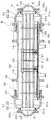
先ず、図1〜図5に示すように、この気密試験装置は、円筒状の本体30と、この本体30の両端開口部に各々配置されたシール蓋体31と、このシール蓋体31の内面31aと管束2の管板6の外周との間を気密に封じるOリング(第1のシール部材)32と、シール蓋体31の内面31bと本体30の外面との間を気密に封じるグランドパッキン(第2のシール部材)33とから概略構成されたものである。 First, as shown in FIGS. 1 to 5, the airtight test apparatus includes a cylindrical
本体30は、内部に管束2が収納されるもので、軸線C方向の長さ寸法がこの気密試験装置によって試験される管束2の長さ寸法よりも短く形成されることにより、管板6を両端開口から外方に突出させた状態で当該管束2を収納するように設計されている。そして、この本体30の両端部に、各々上記シール蓋体31が上記軸線C方向に移動自在に設けられている。 The
このシール蓋体31は、本体30の外周との間に第2のシール部材33を介装可能な間隔を形成して囲繞する円筒状のスライドシェル34と、このスライドシェル34の先端部に一体に形成されて本体30から軸線C方向に離間する方向に向けて漸次縮径する円錐筒状のコニカル35とから構成されたもので、コニカル35の頂部には、上記円錐筒が切頭されることにより、目視検査用の開口部36が形成されている。 The
これにより、シール蓋体31におけるスライドシェル34の内面31bは、本体30の外面に沿う円筒状に形成されている。また、シール蓋体31におけるコニカル35の内面31aは、本体30から軸線C方向に離間する方向に向けて漸次軸線C側に接近する傾斜面によって形成されている。なお、コニカル35の内面31aの軸線Cに対する傾斜角度は、小さ過ぎると管板6外周に当接させるまでの移動距離が極端に長くなり、逆に大き過ぎるとコニカル35に作用する荷重が過大になることから、45±5°の範囲に設定することが好ましい。 Thereby, the inner surface 31 b of the
そして、スライドシェル34の外周に連結フランジ37が立設されるとともに、この連結フランジ37から所定間隔をおいた本体30の外周に、当該連結フランジ37と対向する連結フランジ38が立設され、これら連結フランジ37,38間には、スライドシェル34の移動・固定操作を行うための複数本の連結ボルト39が設けられている。 A
さらに、コニカル35は、軸線C方向に2分割されており、基端部35aに対して先端部35bがフランジ部35cにおいて着脱自在に設けられている。
そして、管板6の外周部に、シール蓋体31のコニカル35の内面31aとの間を気密に封じる上記Oリング32が設けられている。Furthermore, the conical 35 is divided into two in the direction of the axis C, and a
The O-
すなわち、図2に示すように、管板6の外周面には、断面L字状のパッキン押さえ40がボルト41aおよびナット41bによって取り付けられ、このパッキン押さえ40の外面側にOリング32が配置されている。なお、図中符号42は、コニカル35が管板6に当接する際に当該管板6を保護するための当て板である。 That is, as shown in FIG. 2, a packing
ここで、パッキン押さえ40の取付位置は、シール蓋体31を軸線C方向に移動させてコニカル35が当て板42に当接した状態で、パッキン押さえ40およびコニカル35の内面31aからOリング32に圧縮力が作用することにより、このOリング32が僅かに変形して位置決め・固定される位置に設定されている。 Here, the mounting position of the
他方、図3に示すように、シール蓋体31のスライドシェル34の内面31bと、本体30の外面との間に、上記グランドパッキン33が介装されている。そして、スライドシェル34の先端部には、スライドシェル34の板面と平行にボルト43が突設され、このボルト43にL字状のパッキン押さえ44が相対移動自在に設けられている。このパッキン押さえ44は、先端部が本体30の外面とスライドシェル34との間に挿入されてグランドパッキン33の一側に配置されるとともに、ボルト43には、パッキン押さえ44の位置調整・固定用のナット45が螺合されている。 On the other hand, as shown in FIG. 3, the gland packing 33 is interposed between the inner surface 31 b of the
また、スライドシェル34の本体30との対向面には、グランドパッキン33の他側に配置されるストッパ46が固定されている。そして、ナット45を締め付けてグランドパッキン33をパッキン押さえ44とストッパ46によって挟持することにより、シール蓋体31におけるスライドシェル34の内面31bと本体30の外面との間を気密に封じるようになっている。 A
そして、この気密試験装置においては、図4および図5に示すように、管束2を本体30内に搬入および位置決めして支持するための支持装置が備えられている。
これらの図において、符号50は、管束2を本体30の底面上に支持するためのスライディングプレートである。このスライディングプレート50は、その外面が本体30の内面と同じ曲率の円弧面であって、かつ長さ寸法が本体30の軸線C方向の長さ寸法と略等しい帯板状に形成されている。In this airtightness test apparatus, as shown in FIGS. 4 and 5, a support device for carrying the
In these drawings,
このスライディングプレート50の上面には、長手方向の4箇所に各々一対の管束サポート51が立設されている。ここで、各々の箇所における一対の管束サポート51は、図5に示すように、軸線Cを間の挟んだ左右の下方から管束2を支持するように、スライディングプレート50の幅方向の両端部に配置されている。 On the upper surface of the sliding
また、長手方向に隣接する2つの管束サポート51間に、管束2の軸線を本体30の軸線Cと一致させるための調整板(芯出し手段)52が架け渡されてボルト結合されている。そして、軸線Cを挟んで対向するこれら一対の調整板52上に、複数(図では3枚)の管束2のバッフル18が載置されている。ちなみに、調整板52は、管束2のバッフル18を載置した際に、管束2の軸線が本体30の軸線Cと一致する高さ寸法となるように、気密試験を行う管束2ごとに予め製作されたものである。 An adjustment plate (centering means) 52 for causing the axis of the
さらに、軸線C方向の中央の2箇所に設けられた管束サポート51には、各々管束固定バンド用のラグ53が設けられている。また、本体30の底面には、スライディングプレート50の両側に配置されて当該スライディングプレート50の移動を案内するとともに、周方向への位置ブレを防ぐためのサイドストッパ54が固定されている。 Furthermore, the
なお、図中符号55は、管束2を収納した後に、本体30の開口部近傍に水平に仮設されることにより、管束2を水平方向に支持するためのサポートバーである。また、スライディングプレート50の長手方向の両端部、すなわち本体30の開口部近傍であって作業者が操作可能な位置には、各々スライディングプレート50をジャッキアップ可能な一対のジャッキボルト(芯出し手段)56が、軸線Cを通る鉛直線を間に挟んで左右に配置されている。 In addition, the code |
次いで、図6〜図8に基づいて、気密試験時における上記構成からなる気密試験装置への管束2の設置手順について説明する。
先ず、図6(a)に示すように、気密試験を行う管束2に当て板Bを施してワイヤWによって吊り上げ、同図(b)に示すように、バッフル18を支持装置の調整板52上に載置した後に、図5および図6(c)に示すように、一端部を一方のラグ53に連結した管束固定用バンド61をバッフル18の外周に巻回して、他端部を他方のラグ53に連結することにより、管束2を支持装置上に固定する。この際に、バッフル18の上部外周には、保護用の当て板60を介装することが好ましい。Next, a procedure for installing the
First, as shown in FIG. 6 (a), a baffle plate B is applied to the
次いで、図7に示すように、クレーンとリフトあるいはウインチ等を用いて、支持装置上に固定された管束2を本体30内に挿入する。そして、図8に示すように、管束2の管板6を両端部から突出させた状態で本体30内に位置決めした後に、さらに管束2の軸線が本体30の軸線Cと一致していることを確認する。この際に、管束2の軸線が本体30の軸線Cと一致するように調整板52を製作してあるために、大きな芯ズレが生じるおそれは無いものの、若干の芯出し調整が必要な場合には、ジャッキボルト56によってスライディングプレート50を本体30に対して上下させることにより芯出しを行う。 Next, as shown in FIG. 7, the
これと併行して、管束2の管板6の外周に、パッキン押さえ40およびOリング32を取り付ける。また、本体30の外周には、グランドパッキン33およびパッキン押さえ44を取り付ける。 At the same time, a
次に、本体30の両方の端部において、シール蓋体31を送り込む。この際に、スライドシェル34の先端部に突設したボルト43を、パッキン押さえ44に穿設した孔部内に挿入して行く。そして、コニカル35の内面31aがOリング32に当たった位置において、本体30の連結フランジ38とシール蓋体31のスライドシェル34の連結フランジ37間に設けられた連結ボルト39を締め込んで、Oリング32を幾分変形させて固定する。 Next, the
次いで、グランドパッキン33のパッキン押さえ44に挿入したボルト43にナット45を螺合させて締め付けることにより、グランドパッキン33によって、本体30の外面とシール蓋体31のスライドシェル34の内面31bとの間を気密に封じる。 Next, a
このようにして、気密試験装置内に管束2を設置した後に、本体30内に加圧した流体(一般に、耐圧試験の場合は水、気密試験の場合は空気)を注入し、開口部36から目視によって管板6の孔部6aと伝熱管5との間からの漏れの有無を確認する。なお、図1に示すように、管束2の寸法諸元によって、管板6の外周がシール蓋体31のコニカル35の基端部35a側の内面31aに当接している場合には、フランジ部35cのボルトを外して先端部35bを取り外すことにより、開口部36を広くして目視による試験を一層容易に行うことが可能である。 In this way, after the
以上のように、上記構成からなる管束の気密試験装置によれば、本体30の両端部に、各々シール蓋体31を本体30の軸線C方向に移動自在に設けるとともに、シール蓋体31のコニカル35の内面31aに、軸線に対する傾斜角度が45±5°の傾斜面を形成しているために、各々の端部の開口から管板6を突出させて本体30内に収納された管束2に対して、シール蓋体31を軸線方向に移動させることにより、容易にコニカル35の内面31aを管束2の管板6に取り付けたOリング32によって気密に封じることができる。 As described above, according to the tube bundle hermeticity testing apparatus configured as described above, the
したがって、気密試験の対象となる複数の管束2における管板6の径や伝熱管5の長さ寸法が互いに異なることにより、本体30からシール蓋体31内へと延出する管板6の外周部の位置が変わった場合においても、シール蓋体31を軸線C方向に移動させるだけで、容易にその内面31aを管板6の外周部に臨ませて対応することが可能になる。この結果、多様な寸法の管束2に対する気密試験を1つの試験装置によって行うことができ、よって経済性に優れるとともに保管場所の確保や保守管理も容易になる。 Therefore, the outer circumference of the
また、管束2を支持装置上に固定して、本体30内に挿入しているために、設置作業が容易になるとともに、当該支持装置のスライディングプレート50と管束2のバッフル18との間に、予め管束2の軸線を本体30Cの軸線と一致させる寸法に調整しておいた調整板52を介装しているために、シール蓋体31を軸線C方向に移動させるのみで、全周にわたって内面31aと管板6の間隔を均一にして、Oリング32により容易かつ確実にシールすることができる。 Further, since the
さらに、コニカル52を軸線C方向に2分割し、基端部35aに対して先端部35bを取り外し可能にしているために、Oリング32が基端部35a側の内面31aと当接している場合には、先端部35bを取り外すことにより、開口部36を広く確保して、目視の便宜を図ることができる。ちなみに、上記コニカル35を軸線C方向に3分割以上すれば、管板6の外径寸法に応じて、より細かく目視用の開口部36の広さを調整することが可能になる。 Further, when the conical 52 is divided into two in the direction of the axis C and the
また、上記調整板52に加えて、スライディングプレート50に芯出し用のジャッキボルト56を設けているために、より正確な芯出しを行うことが可能になる。しかも、当該ジャッキボルト56を、極力Oリング32の近傍となる本体30の端部に設けているために、これらジャッキボルト56によって行った芯出しを、正しくOリング32の位置に反映させることができる。 In addition to the
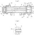
なお、上記実施形態においては、本発明に係る気密試験装置を、図10に示したフローティング・ヘッド式の熱交換器の管束2の気密試験を行うものに適用した場合に付いてのみ説明したが、本発明は、図11に示したUチューブ式の多管式熱交換器の管束14に対する気密試験装置を行うものにも適用することが可能である。 In the above embodiment, the airtightness test apparatus according to the present invention has been described only when it is applied to the airtightness test of the
この場合には、伝熱管15がUチューブであり、よって管束14の一端部側にのみ管板16が設けられていることから、図12の模式図に示すように、本体30の一端部側を鏡板65等によって塞ぎ、管板16を突出させた他端部のみに、上記構成からなるシール蓋体31を設けた気密試験装置とすることにより、同様に気密試験を行うことが可能である。 In this case, since the
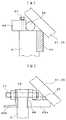
また、上記実施形態においては、図2に示したように、管板6の外周面に断面L字状のパッキン押さえ40をボルト41aおよびナット41bによって取り付け、このパッキン押さえ40の外面側にOリング32を配置した場合についてのみ説明したが、これに限るものではなく、例えば図9(a)に示すように、管板6の厚さ寸法が小さい場合には、当該管板6の外周面に立方体状の金物66をボルト67によって固定し、この金物66の外面側にOリング32を配置することもできる。 In the above embodiment, as shown in FIG. 2, a
さらに、管束2の形式によっては、その管板6が図10に示したシェル1のフランジ1aおよびヘッダ4のフランジ4aに挿通されたボルトによって、いわゆる3枚締めによって固定されるものがある。このような管板6においては、上記ボルトが挿通されるボルト穴が穿設されているため、単に管板6の外周とシール蓋体31のコニカル35との間にOリング32を介装したのみでは、両者間の気密性を確保することができない。 Further, depending on the type of the
このような場合には、図9(b)に示すように、管板6の両端面の外周部に、ガスケット68を介して一対のシーリングリング69a、69bを配置し、当該シーリングリング69a、69bおよび管板6のボルト穴70に挿通したボルト71を締め付けるとともに、シーリングリング69aの外周に、シール蓋体31のコニカル35との間を気密に封じるOリング32を配置すればよい。すなわち、本発明において、シール蓋体の内面との間を気密に封じる第1のシール部材(Oリング32)を管板の外周部に設ける、とはこのような場合も含むものである。 In such a case, as shown in FIG. 9 (b), a pair of sealing
また、芯出し手段についても、上記実施形態において示した調整板52に限定されるものではなく、当該調整板52に代えて、例えばジャッキボルト等を設置することにより、同様に管束2の軸線を本体30の軸線Cと一致させる芯出しを行うことができる。 Further, the centering means is not limited to the
2、14 熱交換器用管束
5、15 伝熱管
6、16 管板
6a 孔部
30 本体
31 シール蓋体
32 Oリング(第1のシール部材)
33 グランドパッキン(第2のシール部材)
35 コニカル
31a 内面(傾斜面)
52 調整板(芯出し手段)
C 軸線2, 14 Heat
33 Gland packing (second seal member)
35 Conical 31a Inner surface (inclined surface)
52 Adjustment plate (centering means)
C axis
Claims (4)
Translated fromJapanese一端部側の開口から上記管板を突出させて内部に上記熱交換用管束を収納するとともに他端部が塞がれた筒状の本体と、この本体の上記一端部に当該本体の軸線方向に移動自在に設けられたシール蓋体と、上記管板の外周部に設けられて上記シール蓋体の内面との間を気密に封じる第1のシール部材と、上記シール蓋体と上記本体の外面との間を気密に封じる第2のシール部材とを備えてなり、
かつ上記シール蓋体は、上記第1のシール部材が設けられた上記内面が、上記本体から軸線方向に離間する方向に向けて漸次縮径する円錐筒状の傾斜面によって形成されていることを特徴とする熱交換器用管束の気密試験装置。A plurality of heat transfer tubes made ofU-tubes arranged in parallel, and a tube plate disposed atan end portionon the opening side of these heat transfer tubes, the hole of the heat transfer tube being formed in the hole formed in the tube plate an apparatus for testing the air-tightness betweenthe end of the heat transfer tube and the hole of the tube plate of the heat exchanger tube bundleto the end portion is fixedly inserted,
A tubular main body in which the tube sheet is protruded from the opening on one end side to house the heat exchange tube bundle and the other end is closed, and the one end of the main body is in the axial direction of the main body A first sealing member that is provided on the outer periphery of the tube plate and hermetically seals between the inner surface of the sealing lid, the sealing lid, and the main body. A second sealing member that hermetically seals between the outer surface,
The seal lidis formed by aconical cylindrical inclined surfacewhose inner surfaceprovided with the first seal member is graduallyreduced in diameter in a direction away from the main body in the axial direction. A hermetic test device for heat exchanger tube bundles.
両端部の開口から各々上記管板を突出させて内部に上記熱交換用管束を収納する筒状の本体と、この本体の各々の上記端部に当該本体の軸線方向に移動自在に設けられたシール蓋体と、上記管板の外周部に設けられて上記シール蓋体の内面との間を気密に封じる第1のシール部材と、上記シール蓋体と上記本体の外面との間を気密に封じる第2のシール部材とを備えてなり、
かつ各々の上記シール蓋体は、上記第1のシール部材が設けられた上記内面が、上記本体から軸線方向に離間する方向に向けて漸次縮径する円錐筒状の傾斜面によって形成されていることを特徴とする熱交換器用管束の気密試験装置。A plurality of heat exchanger tubes which are parallel disposed, and a tube plate arranged on the end of these heat transfer tubes, andthe end of the heat transfer tube is inserted into a hole formed in the tube plate an apparatus for testing the air-tightness betweenthe end portion and the hole of the tube plate of the heat transfer tube of the fixed heat exchanger tube bundle,
A tubular main body for projecting the tube sheet from the openings at both ends to house the heat exchanging tube bundle inside, and provided at each end of the main body so as to be movable in the axial direction of the main body. A first sealing member that is provided on the outer peripheral portion of the tube plate and hermetically seals between the inner surface of the seal lid, and an airtight between the seal lid and the outer surface of the main body; A second sealing member for sealing,
Each of the seal lidsis formed by aconical cylindrical inclined surfacein which the inner surfaceprovided with the first seal member is graduallyreduced in diameter in a direction away from the main body in the axial direction. An air tightness test apparatus for heat exchanger tube bundles.
Priority Applications (3)
| Application Number | Priority Date | Filing Date | Title |
|---|---|---|---|
| JP2012221363AJP6024357B2 (en) | 2012-10-03 | 2012-10-03 | Air tightness test equipment for heat exchanger tube bundles |
| KR1020130106755AKR20140043862A (en) | 2012-10-03 | 2013-09-05 | Leak testing apparatus of tube bundle for heat exchanger |
| CN201310455768.3ACN103712752B (en) | 2012-10-03 | 2013-09-30 | The air tightness tester of heat exchanger pipe beam |
Applications Claiming Priority (1)
| Application Number | Priority Date | Filing Date | Title |
|---|---|---|---|
| JP2012221363AJP6024357B2 (en) | 2012-10-03 | 2012-10-03 | Air tightness test equipment for heat exchanger tube bundles |
Publications (2)
| Publication Number | Publication Date |
|---|---|
| JP2014074613A JP2014074613A (en) | 2014-04-24 |
| JP6024357B2true JP6024357B2 (en) | 2016-11-16 |
Family
ID=50405905
Family Applications (1)
| Application Number | Title | Priority Date | Filing Date |
|---|---|---|---|
| JP2012221363AExpired - Fee RelatedJP6024357B2 (en) | 2012-10-03 | 2012-10-03 | Air tightness test equipment for heat exchanger tube bundles |
Country Status (3)
| Country | Link |
|---|---|
| JP (1) | JP6024357B2 (en) |
| KR (1) | KR20140043862A (en) |
| CN (1) | CN103712752B (en) |
Families Citing this family (13)
| Publication number | Priority date | Publication date | Assignee | Title |
|---|---|---|---|---|
| CN105675222A (en)* | 2014-11-20 | 2016-06-15 | 无锡小天鹅股份有限公司 | Detection tool for clothes dryer condenser |
| CN105203269A (en)* | 2015-09-16 | 2015-12-30 | 东方电气(广州)重型机器有限公司 | Heat exchange tube and tube plate seal-welding helium leakage-detection device |
| CN105758593B (en)* | 2016-05-17 | 2018-05-29 | 中广核检测技术有限公司 | Method for positioning and detecting water leakage is quantified using nuclear boiler heat-transfer pipe helium mass spectrum leak detection equipment |
| KR102089205B1 (en)* | 2016-07-07 | 2020-03-13 | 주식회사 발카 | Practice device and practice method of seal construction |
| CN107192515B (en)* | 2017-07-07 | 2023-06-16 | 上海长园电子材料有限公司 | Sealing detection device for heat exchange tube of heat exchanger |
| CN108020386A (en)* | 2018-01-24 | 2018-05-11 | 青岛达能环保设备股份有限公司 | The pre- leak detection system of large-scale low-temperature economizer |
| CN113566614B (en)* | 2020-04-28 | 2024-06-18 | 杭州科百特科技有限公司 | Heat exchange equipment and manufacturing method thereof |
| CN111693222B (en)* | 2020-05-08 | 2022-08-26 | 中国船舶重工集团公司第七二五研究所 | Helium mass spectrum leak detection method for detecting sealing performance of printed plate heat exchanger |
| CN111879619B (en)* | 2020-07-14 | 2023-10-03 | 东方电气(广州)重型机器有限公司 | Quick pressure test device of tube bank subassembly |
| CN114486308B (en)* | 2021-12-30 | 2024-05-10 | 北京动力机械研究所 | Heat exchange characteristic experimental method for micro tube bundle |
| CN115077818A (en)* | 2022-07-21 | 2022-09-20 | 斯必高空气冷却技术(张家口)有限公司 | A heat exchanger tube bundle single-tube leak detection device and a heat exchanger tube bundle leak detection and blocking method |
| CN116412974B (en)* | 2023-06-09 | 2023-10-31 | 江苏奥琳斯邦装备科技股份有限公司 | Sealing detection device for heat exchanger |
| CN116818221B (en)* | 2023-08-29 | 2023-11-10 | 西安航宇动力控制科技有限公司 | Microminiature electric gear fuel pump tightness detection system |
Family Cites Families (6)
| Publication number | Priority date | Publication date | Assignee | Title |
|---|---|---|---|---|
| US4199975A (en)* | 1976-04-12 | 1980-04-29 | Westinghouse Electric Corp. | Method and apparatus for locating a defective tube of a liquid metal-to-water tube type heat exchanger |
| JPS62165541U (en)* | 1986-04-11 | 1987-10-21 | ||
| JPS6358226A (en)* | 1986-08-29 | 1988-03-14 | Toshiba Corp | Leak testing device for shell and tube heat exchanger |
| JPH075391Y2 (en)* | 1989-09-29 | 1995-02-08 | 出光エンジニアリング株式会社 | Tube bundle tester for heat exchanger |
| JPH08304219A (en)* | 1995-05-12 | 1996-11-22 | Hitachi Ltd | Apparatus and method for inspecting heat transfer tube of heat exchanger |
| CN202177490U (en)* | 2011-07-18 | 2012-03-28 | 天津舜天达天然气有限公司 | Inflating tool for hunting leak of tube-type heat exchanger |
- 2012
- 2012-10-03JPJP2012221363Apatent/JP6024357B2/ennot_activeExpired - Fee Related
- 2013
- 2013-09-05KRKR1020130106755Apatent/KR20140043862A/ennot_activeCeased
- 2013-09-30CNCN201310455768.3Apatent/CN103712752B/enactiveActive
Also Published As
| Publication number | Publication date |
|---|---|
| KR20140043862A (en) | 2014-04-11 |
| CN103712752A (en) | 2014-04-09 |
| CN103712752B (en) | 2017-06-30 |
| JP2014074613A (en) | 2014-04-24 |
Similar Documents
| Publication | Publication Date | Title |
|---|---|---|
| JP6024357B2 (en) | Air tightness test equipment for heat exchanger tube bundles | |
| US20210199393A1 (en) | Heat exchanger closure assemblies and methods of using and installing the same | |
| US4197907A (en) | Floating head support system for shell and tube heat exchanger | |
| CN105486460B (en) | A kind of pressure testing system for movable tube sheets heat exchanger | |
| CN105606308B (en) | A kind of split type pressure testing system for movable tube sheets heat exchanger | |
| KR101789912B1 (en) | Installation structure for tube ends of heat exchanger and heat exchanger having the same | |
| CN101701657B (en) | Device and method for repairing expansion joint of gas pipeline | |
| US10663230B2 (en) | True countercurrent heat exchanger with sealing arrangement | |
| KR200439965Y1 (en) | Heat exchanger leak tester | |
| US4750554A (en) | Internal tube sheet sealing apparatus assembly for tubular heat exchangers | |
| CN112923759A (en) | Vertical heat exchanger | |
| KR20200001697A (en) | Apparatus and method for testing leakage of heat exchanger with tube bundle | |
| CN208254746U (en) | Pressure test tool | |
| CN204007221U (en) | A kind of single tube journey movable tube sheets heat exchanger with expansion joint guider | |
| CN107084887B (en) | Detachable tube bundle tube side reliability pressure testing device | |
| GB2524260A (en) | Air cooler for hydrogen process application having special header design and repair procedure | |
| CN219995977U (en) | Single tube Cheng Fu head type heat exchanger | |
| CN210802821U (en) | U-shaped pipe pressing leakage detection test device | |
| CN209672882U (en) | Shell and tube cooler with online leakage detection and leak stopping maintenance function | |
| CN213120203U (en) | Heat exchanger tube box structure and heat exchanger | |
| CN110067909B (en) | Sealing device and method for emergency maintenance of pipeline | |
| JPH0449510Y2 (en) | ||
| CN110143375B (en) | Anti-leakage structure capable of absorbing thermal expansion | |
| JPH0596765U (en) | Tube heat exchanger | |
| Singla | Special Flange Joints Used in Floating-Head Shell-and-Tube Heat Exchangers. |
Legal Events
| Date | Code | Title | Description |
|---|---|---|---|
| A621 | Written request for application examination | Free format text:JAPANESE INTERMEDIATE CODE: A621 Effective date:20150424 | |
| A977 | Report on retrieval | Free format text:JAPANESE INTERMEDIATE CODE: A971007 Effective date:20160218 | |
| A131 | Notification of reasons for refusal | Free format text:JAPANESE INTERMEDIATE CODE: A131 Effective date:20160301 | |
| A521 | Request for written amendment filed | Free format text:JAPANESE INTERMEDIATE CODE: A523 Effective date:20160425 | |
| TRDD | Decision of grant or rejection written | ||
| A01 | Written decision to grant a patent or to grant a registration (utility model) | Free format text:JAPANESE INTERMEDIATE CODE: A01 Effective date:20160913 | |
| A61 | First payment of annual fees (during grant procedure) | Free format text:JAPANESE INTERMEDIATE CODE: A61 Effective date:20160926 | |
| R150 | Certificate of patent or registration of utility model | Ref document number:6024357 Country of ref document:JP Free format text:JAPANESE INTERMEDIATE CODE: R150 | |
| R250 | Receipt of annual fees | Free format text:JAPANESE INTERMEDIATE CODE: R250 | |
| R250 | Receipt of annual fees | Free format text:JAPANESE INTERMEDIATE CODE: R250 | |
| R250 | Receipt of annual fees | Free format text:JAPANESE INTERMEDIATE CODE: R250 | |
| R250 | Receipt of annual fees | Free format text:JAPANESE INTERMEDIATE CODE: R250 | |
| R250 | Receipt of annual fees | Free format text:JAPANESE INTERMEDIATE CODE: R250 | |
| LAPS | Cancellation because of no payment of annual fees |