JP6023785B2 - Wireless power transmission control method and wireless power transmission device - Google Patents
Wireless power transmission control method and wireless power transmission deviceDownload PDFInfo
- Publication number
- JP6023785B2 JP6023785B2JP2014501005AJP2014501005AJP6023785B2JP 6023785 B2JP6023785 B2JP 6023785B2JP 2014501005 AJP2014501005 AJP 2014501005AJP 2014501005 AJP2014501005 AJP 2014501005AJP 6023785 B2JP6023785 B2JP 6023785B2
- Authority
- JP
- Japan
- Prior art keywords
- source
- power
- resonator
- unit
- target device
- Prior art date
- Legal status (The legal status is an assumption and is not a legal conclusion. Google has not performed a legal analysis and makes no representation as to the accuracy of the status listed.)
- Expired - Fee Related
Links
Images


Classifications
- H—ELECTRICITY
- H02—GENERATION; CONVERSION OR DISTRIBUTION OF ELECTRIC POWER
- H02J—CIRCUIT ARRANGEMENTS OR SYSTEMS FOR SUPPLYING OR DISTRIBUTING ELECTRIC POWER; SYSTEMS FOR STORING ELECTRIC ENERGY
- H02J50/00—Circuit arrangements or systems for wireless supply or distribution of electric power
- H02J50/10—Circuit arrangements or systems for wireless supply or distribution of electric power using inductive coupling
- H02J50/12—Circuit arrangements or systems for wireless supply or distribution of electric power using inductive coupling of the resonant type
- G—PHYSICS
- G01—MEASURING; TESTING
- G01R—MEASURING ELECTRIC VARIABLES; MEASURING MAGNETIC VARIABLES
- G01R23/00—Arrangements for measuring frequencies; Arrangements for analysing frequency spectra
- G01R23/02—Arrangements for measuring frequency, e.g. pulse repetition rate; Arrangements for measuring period of current or voltage
- G01R23/04—Arrangements for measuring frequency, e.g. pulse repetition rate; Arrangements for measuring period of current or voltage adapted for measuring in circuits having distributed constants
- G—PHYSICS
- G01—MEASURING; TESTING
- G01R—MEASURING ELECTRIC VARIABLES; MEASURING MAGNETIC VARIABLES
- G01R27/00—Arrangements for measuring resistance, reactance, impedance, or electric characteristics derived therefrom
- G01R27/02—Measuring real or complex resistance, reactance, impedance, or other two-pole characteristics derived therefrom, e.g. time constant
- G01R27/04—Measuring real or complex resistance, reactance, impedance, or other two-pole characteristics derived therefrom, e.g. time constant in circuits having distributed constants, e.g. having very long conductors or involving high frequencies
- H—ELECTRICITY
- H02—GENERATION; CONVERSION OR DISTRIBUTION OF ELECTRIC POWER
- H02J—CIRCUIT ARRANGEMENTS OR SYSTEMS FOR SUPPLYING OR DISTRIBUTING ELECTRIC POWER; SYSTEMS FOR STORING ELECTRIC ENERGY
- H02J50/00—Circuit arrangements or systems for wireless supply or distribution of electric power
- H02J50/40—Circuit arrangements or systems for wireless supply or distribution of electric power using two or more transmitting or receiving devices
- H02J50/402—Circuit arrangements or systems for wireless supply or distribution of electric power using two or more transmitting or receiving devices the two or more transmitting or the two or more receiving devices being integrated in the same unit, e.g. power mats with several coils or antennas with several sub-antennas
- H—ELECTRICITY
- H02—GENERATION; CONVERSION OR DISTRIBUTION OF ELECTRIC POWER
- H02J—CIRCUIT ARRANGEMENTS OR SYSTEMS FOR SUPPLYING OR DISTRIBUTING ELECTRIC POWER; SYSTEMS FOR STORING ELECTRIC ENERGY
- H02J50/00—Circuit arrangements or systems for wireless supply or distribution of electric power
- H02J50/50—Circuit arrangements or systems for wireless supply or distribution of electric power using additional energy repeaters between transmitting devices and receiving devices
- H—ELECTRICITY
- H02—GENERATION; CONVERSION OR DISTRIBUTION OF ELECTRIC POWER
- H02J—CIRCUIT ARRANGEMENTS OR SYSTEMS FOR SUPPLYING OR DISTRIBUTING ELECTRIC POWER; SYSTEMS FOR STORING ELECTRIC ENERGY
- H02J50/00—Circuit arrangements or systems for wireless supply or distribution of electric power
- H02J50/80—Circuit arrangements or systems for wireless supply or distribution of electric power involving the exchange of data, concerning supply or distribution of electric power, between transmitting devices and receiving devices
- H—ELECTRICITY
- H02—GENERATION; CONVERSION OR DISTRIBUTION OF ELECTRIC POWER
- H02J—CIRCUIT ARRANGEMENTS OR SYSTEMS FOR SUPPLYING OR DISTRIBUTING ELECTRIC POWER; SYSTEMS FOR STORING ELECTRIC ENERGY
- H02J50/00—Circuit arrangements or systems for wireless supply or distribution of electric power
- H02J50/90—Circuit arrangements or systems for wireless supply or distribution of electric power involving detection or optimisation of position, e.g. alignment
- H—ELECTRICITY
- H02—GENERATION; CONVERSION OR DISTRIBUTION OF ELECTRIC POWER
- H02J—CIRCUIT ARRANGEMENTS OR SYSTEMS FOR SUPPLYING OR DISTRIBUTING ELECTRIC POWER; SYSTEMS FOR STORING ELECTRIC ENERGY
- H02J7/00—Circuit arrangements for charging or depolarising batteries or for supplying loads from batteries
- H02J7/0013—Circuit arrangements for charging or depolarising batteries or for supplying loads from batteries acting upon several batteries simultaneously or sequentially
- H—ELECTRICITY
- H02—GENERATION; CONVERSION OR DISTRIBUTION OF ELECTRIC POWER
- H02J—CIRCUIT ARRANGEMENTS OR SYSTEMS FOR SUPPLYING OR DISTRIBUTING ELECTRIC POWER; SYSTEMS FOR STORING ELECTRIC ENERGY
- H02J7/00—Circuit arrangements for charging or depolarising batteries or for supplying loads from batteries
- H02J7/0042—Circuit arrangements for charging or depolarising batteries or for supplying loads from batteries characterised by the mechanical construction
- H02J7/0045—Circuit arrangements for charging or depolarising batteries or for supplying loads from batteries characterised by the mechanical construction concerning the insertion or the connection of the batteries
- H—ELECTRICITY
- H02—GENERATION; CONVERSION OR DISTRIBUTION OF ELECTRIC POWER
- H02J—CIRCUIT ARRANGEMENTS OR SYSTEMS FOR SUPPLYING OR DISTRIBUTING ELECTRIC POWER; SYSTEMS FOR STORING ELECTRIC ENERGY
- H02J7/00—Circuit arrangements for charging or depolarising batteries or for supplying loads from batteries
- H02J7/0042—Circuit arrangements for charging or depolarising batteries or for supplying loads from batteries characterised by the mechanical construction
- H02J7/0044—Circuit arrangements for charging or depolarising batteries or for supplying loads from batteries characterised by the mechanical construction specially adapted for holding portable devices containing batteries
Landscapes
- Engineering & Computer Science (AREA)
- Power Engineering (AREA)
- Computer Networks & Wireless Communication (AREA)
- Physics & Mathematics (AREA)
- General Physics & Mathematics (AREA)
- Charge And Discharge Circuits For Batteries Or The Like (AREA)
- Transmitters (AREA)
Description
Translated fromJapanese以下の開示は、無線電力送信の制御方法、及び無線電力送信装置に関する。The following disclosure relates to awireless power transmission control method and a wireless power transmission apparatus .
無線電力は、電磁結合によって無線電力送信装置から無線電力受信装置に伝えられるエネルギーを意味する。
したがって、無線電力送信システムは、電力を無線で送信するソース装置と電力を無線で受信するターゲット装置を含む。
ここで、ソース装置は無線電力送信装置と称する。また、ターゲット装置は無線電力受信装置と称する。The wireless power means energy transmitted from the wireless power transmitting device to the wireless power receiving device by electromagnetic coupling.
Accordingly, the wireless power transmission system includes a source device that wirelessly transmits power and a target device that wirelessly receives power.
Here, the source device is referred to as a wireless power transmission device. The target device is referred to as a wireless power receiving device.
ソース装置は、ソース共振器を備え、ターゲット装置はターゲット共振器を備える。
ソース共振器とターゲット共振器との間に電磁結合又は共振カップリングが形成される。無線環境の特性上、ソース共振器及びターゲット共振器の間の距離が時間によって変わる可能性が高く、両共振器の整合条件も変化し得る。
これにより電力送信の効率が減少することがある。The source device includes a source resonator, and the target device includes a target resonator.
An electromagnetic coupling or resonant coupling is formed between the source resonator and the target resonator. Due to the characteristics of the wireless environment, the distance between the source resonator and the target resonator is likely to change with time, and the matching conditions of both resonators may also change.
This may reduce power transmission efficiency.
本発明は上記従来の無線電力送信システムを鑑みてなされたものであって、本発明の目的は、複数の無線電力受信装置へ効率的に電力を送信することのできる無線電力送信システムを提供することにある。 The present invention has been made in view of the above-described conventional wireless power transmission system, and an object of the present invention is to provide a wireless power transmission system capable of efficiently transmitting power to a plurality of wireless power receiving apparatuses. There is.
本発明の一態様によれば無線電力送信の制御方法は、電力を無線で受信する複数のターゲット装置を検出するステップと、前記複数のターゲット装置の内の1つ以上に送信する電力に基づくか、又は前記複数のターゲット装置の内の1つ以上の識別子(ID)情報に基づくか、又はその両方に基づいて、複数のソース共振部からいずれか1つのソース共振部を選択するステップと、前記選択されたソース共振部を用いてターゲット装置に電力を無線で送信するステップとを有し、前記選択するステップは、第1ソース共振部に隣接する第1ターゲット装置に送信する電力P1と、第2ソース共振部に隣接する第2ターゲット装置に送信する電力P2を確認するステップと、前記電力P2より前記電力P1が予め設定された値よりも大きければ、前記第1ソース共振部を選択し、前記電力P1より前記電力P2が前記予め設定された値よりも大きければ、前記第2ソース共振部を選択するステップと、を含むことを特徴とする。According to an aspect of the present invention, is a wireless power transmission control method based on detecting a plurality of target devices that receive power wirelessly andpower transmitted to one or more of the plurality of target devices. Selecting any one source resonator from a plurality of source resonators basedon one or more identifier (ID) information of the plurality of target devices , or both, andhave a transmitting power wirelessly to the target device using the source resonator unitselected, said selecting step includes a power P1 to be transmitted to the first target device adjacent to the first source resonating portion, the A step of confirming the power P2 transmitted to the second target device adjacent to the two-source resonance unit, and if the power P1 is greater than a preset value from the power P2 Wherein the first select source resonator unit, if the power P2 from the power P1 is greater than said preset value, characterized in thatit comprises the steps of: selecting the second source resonating unit.
前記複数のターゲット装置を検出するステップは、ウェイクアップリクエスト信号をブロードキャストするステップと、前記複数のターゲット装置の内の1つ以上から前記ウェイクアップリクエスト信号に応答する1つ以上の応答信号を受信するステップとを含み、前記1つ以上の応答信号は、当該ターゲット装置の識別子(ID)情報、又は当該ターゲット装置で用いられる電力に関する情報、又はその両方を含むことが好ましい。
前記複数のターゲット装置を検出するステップは、複数のソース共振部を用いてウェイクアップリクエスト信号をブロードキャストするステップと、前記複数のターゲット装置から前記ウェイクアップリクエスト信号に応答する1つ以上の応答信号を受信するステップと、を含むことが好ましい。
前記選択するステップは、前記複数のソース共振部の内から前記複数のターゲット装置の内の1つ以上に送信する電力が最も大きいソース共振部を選択するステップを含むことが好ましい。
前記第1ターゲット装置の共振器である第1ターゲット共振器及び前記第2ターゲット装置の共振器である第2ターゲット共振器は、サイズ又はコイルの巻数が互いに異なることが好ましい。
前記選択するステップは、前記複数のソース共振部の内から前記複数のターゲット装置の内の1つ以上に対するカップリングファクターが最も大きいソース共振部を選択するステップを含むことが好ましい。The step of detecting the plurality of target devices includes broadcasting a wakeup request signal and receiving one or more response signals in response to the wakeup request signal from one or more of the plurality of target devices. Preferably, the one or more response signals include identifier (ID) information of the target device, information regardingpower used by the target device, or both.
The steps of detecting the plurality of target devices include: broadcasting a wakeup request signal using a plurality of source resonance units; and one or more response signals responding to the wakeup request signal from the plurality of target devices.receiving, it will be preferableto include.
It said step of selecting, it isnot preferableto include the step of selecting the largest source resonator unitpower to be transmitted to one or more of the plurality of target devices from among the plurality of source resonatingunit.
Before Stories second target resonator is a first target resonator and the resonator of the second target device is a resonator of the first target device preferably turns size or coil are different from each other.
It said selecting steppreferably includes the step of selecting the largest source resonator portion coupling factor for one or more of the plurality of target devices from among the plurality of source resonating unit.
前記選択するステップは、第1ソース共振部に隣接する第1ターゲット装置に送信する電力P1と、第2ソース共振部に隣接する第2ターゲット装置に送信する電力P2を確認するステップと、前記電力P1と前記電力P2との差が予め設定された値以下であれば、前記第1及び第2ターゲット装置の内の1つ以上に対するカップリングファクターを確認するステップと、前記第1ソース共振部及び前記第2ソース共振部の内から前記カップリングファクターがより大きいソース共振部を選択するステップとを含むことが好ましい。
前記選択するステップは、第1ソース共振部に隣接する第1ターゲット装置に送信する電力P1と、第2ソース共振部に隣接する第2ターゲット装置に送信する電力P2を確認するステップと、前記電力P1と前記電力P2の差が予め設定された値以下であれば、前記第1ソース共振部及び前記第2ソース共振部を交互にターンオン又はターンオフさせるステップとを含むことが好ましい。
前記選択されたソース共振部に隣接するターゲット装置の電力受信が終了すると、前記選択されたソース共振部をターンオフさせるステップと、前記複数のソース共振部の内の前記ターゲット装置から電力を無線で受信する低電力デバイスに隣接するソース共振部をターンオンさせるステップとをさらに有することが好ましい。
前記選択されたソース共振部から前記選択されたソース共振部に隣接するターゲット装置に無線で送信される電力は、前記選択されたソース共振部に隣接するターゲット装置で用いられる電力か、又は前記低電力デバイスで用いられる電力、又はその両方に基づいて決定されることが好ましい。
前記選択するステップは、前記選択されたソース共振部をターンオンさせるステップと、前記選択されたソース共振部以外の1つ以上のソース共振部をターンオフさせるステップとを含むことが好ましい。The selecting step includes the step of confirming thepower P1 transmitted to the first target device adjacent to the first source resonator, thepower P2 transmitted to the second target device adjacent to the second source resonator, and thepower If a difference between P1 and thepower P2 is equal to or less than a preset value, a step of checking a coupling factor for one or more of the first and second target devices; Selecting a source resonator having a larger coupling factor from the second source resonator.
The selecting step includes the step of confirming thepower P1 transmitted to the first target device adjacent to the first source resonator, thepower P2 transmitted to the second target device adjacent to the second source resonator, and thepower If the difference between P1 and thepower P2 is equal to or less than a preset value, the method preferably includes a step of alternately turning on or turning off the first source resonance unit and the second source resonance unit.
When power reception of the target device adjacent to the selected source resonance unit is completed, the step of turning off the selected source resonance unit, and wirelessly receiving power from the targetdevice among the plurality of source resonance units And turning on the source resonator adjacent to the low power device.
Thepower transmittedwirelessly to the target device from the selected source resonating unit adjacent to the source resonator portion which is the selectedpower or used by the target device adjacent to the source resonator unit said selected or the low Preferably, it is determined based on thepower used by the power device, or both.
Preferably, the selecting step includes a step of turning on the selected source resonator unit and a step of turning off one or more source resonator units other than the selected source resonator unit.
本発明の一態様によれば無線電力送信装置は、電力を無線で受信する複数のターゲット装置を検出する検出部と、前記複数のターゲット装置の1つ以上に送信する電力、又は前記複数のターゲット装置の内の1つ以上の識別子(ID)情報に基づくか、又はその両方に基づいて、複数のソース共振部からいずれか1つのソース共振部を選択する制御部と、前記選択されたソース共振部を用いてターゲット装置に電力を無線で送信する電力送信部とを備え、前記制御部は、第1ソース共振部に隣接する第1ターゲット装置に送信する電力P1と、第2ソース共振部に隣接する第2ターゲット装置に送信する電力P2を確認する第1プロセッサと、前記電力P2より前記電力P1が予め設定された値よりも大きければ前記第1ソース共振部を選択し、前記電力P1より前記電力P2が前記予め設定された値よりも大きければ前記第2ソース共振部を選択する第2プロセッサとを含むことを特徴とする。Wireless power transmitter according to one aspect of the present invention includes a detection unit for detecting a plurality of target devices that receive power wirelessly,the power transmitting one or more of the plurality of target devices, ora plurality of targets A controller that selects one source resonator from a plurality of source resonators basedon one or more identifier (ID) information in the device , or both, and the selected source resonance Beiexample a power transmission unit for transmitting power wirelessly to the target device by using apart, the control unit includes a power P1 to be transmitted to the first target device adjacent to the first source resonating portion, the second source resonating unit A first processor for checking the power P2 to be transmitted to the second target device adjacent to the first target resonance unit if the power P1 is larger than a preset value from the power P2 , Wherein the power P1 from the power P2 includes a second processor for selecting the second source resonating portion is greater than the preset value.
前記検出部は、ウェイクアップリクエスト信号をブロードキャストし、前記複数のターゲット装置の内の1つ以上から前記ウェイクアップリクエスト信号に応答する1つ以上の応答信号を受信する通信部を含み、前記応答信号の内の1つ以上は、当該ターゲット装置の識別子(ID)情報、又は当該ターゲット装置で用いられる電力に関する情報、又はその両方を含むことが好ましい。
前記制御部は、前記複数のソース共振部の内から前記複数のターゲット装置の内の1つに送信する電力が最も大きいソース共振部、又は前記複数のターゲット装置の内の1つに対するカップリングファクターが最も大きいソース共振部を選択することが好ましい。
前記制御部の第2プロセッサは、前記電力P1と前記電力P2との差が前記設定された値以下であれば、前記第1及び第2ターゲット装置の内の1つに対するカップリングファクターを確認し、前記第1ソース共振部及び前記第2ソース共振部のうち前記カップリングファクターがより大きいソース共振部を選択することが好ましい。
前記第2プロセッサは、前記電力P1と前記電力P2との差が予め設定された値以下であれば、前記第1ソース共振部及び前記第2ソース共振部をターンオン又はターンオフさせることが好ましい。
前記制御部は、前記選択されたソース共振部に隣接するターゲット装置の電力受信が終了すると、前記選択されたソース共振部をターンオフさせ、前記複数のソース共振部の内の前記ターゲット装置から電力を無線で受信する低電力デバイスに隣接するソース共振部をターンオンさせることが好ましい。The detection unit includes a communication unit that broadcasts a wakeup request signal and receives one or more response signals in response to the wakeup request signal from one or more of the plurality of target devices, the response signal It is preferable that one or more of these include identifier (ID) information of the target device, information regardingpower used in the target device, or both.
The control unit has a coupling factor for the source resonance unit having the largestpower to be transmitted from the plurality of source resonance units to one of the plurality of target devices, or one of the plurality of target devices. It is preferable to select the source resonance part having the largest value.
The second processor of the controller checks a coupling factor for one of the first and second target devices if the difference between thepower P1 and thepower P2 is less than or equal to the set value. Preferably, a source resonance part having a larger coupling factor isselected from the first source resonance part and the second source resonance part.
If the difference between thepower P1 and thepower P2 is equal to or less than a preset value, the second processor may turn on or off the first source resonance unit and the second source resonance unit.
When the target device adjacent to the selected source resonance unit finishes receiving power, the control unit turns off the selected source resonance unit and receives power from the targetdevice among the plurality of source resonance units. It is preferable to turn on the source resonator adjacent to the low power device receiving wirelessly.
前記選択されたソース共振部から前記選択されたソース共振部に隣接するターゲット装置に無線で送信される電力は、前記選択されたソース共振部に隣接するターゲット装置で用いられる電力、又は前記低電力デバイスで用いられる電力、又はその両方に基づいて決定されることが好ましい。
前記制御部は、前記低電力デバイスの電力受信が終了すると、前記選択されたソース共振部に隣接するターゲット装置で用いられる電力、又は前記選択されたソース共振部に隣接するターゲット装置で受信された電力、又はその両方に基づいて前記選択されたソース共振部に隣接するターゲット装置に無線で送信する電力を制御することが好ましい。
前記電力送信部は、複数のソース共振部を含み、前記複数のソース共振部の内の1つ以上は、アレイ状に配列される複数の共振器を含むことが好ましい。
前記複数のソース共振部のそれぞれは、ソース共振部識別子によって区分され、前記制御部は、前記複数のソース共振部のソース共振部識別子を用いて前記複数のターゲット装置の位置を認識することが好ましい。Power transmittedwirelessly to the target device adjacent to the source resonator portion which is the selected from the selected source resonating unit,the power used by the target device adjacent to the source resonator unit said selected or the low power It is preferably determined based on thepower used by the device, or both.
When the power reception of the low-power device is completed, the control unit receivespower used by a target device adjacent to the selected source resonance unit or received by a target device adjacent to the selected source resonance unit. Preferably, thepower transmitted wirelessly to the target device adjacent to the selected source resonator is controlled based on thepower or both.
Preferably, the power transmission unit includes a plurality of source resonance units, and at least one of the plurality of source resonance units includes a plurality of resonators arranged in an array.
Preferably, each of the plurality of source resonance units is divided by a source resonance unit identifier, and the control unit recognizes positions of the plurality of target devices using a source resonance unit identifier of the plurality of source resonance units. .
本発明に係る無線電力送信の制御方法、及び無線電力送信装置によれば、複数の無線電力受信装置に効率的な無線電力送信が可能であるという効果がある。従って、複数の無線電力受信装置へ効率的に電力を送信することによって無線電力送信システムの効率を高めることができるという効果がある。
また、異種の無線電力受信装置へ効率的に無線電力を送信することができるという効果がある。
また、異種の無線電力受信装置及び同じ種類の無線電力受信装置へ同時に電力を送信することができるという効果がある。According to thewireless power transmission control method and the wireless power transmission apparatus according to the present invention, there is an effect that efficient wireless power transmission is possible to a plurality of wireless power reception apparatuses. Therefore, there is an effect that the efficiency of the wireless power transmission system can be increased by efficiently transmitting power to a plurality of wireless power receiving apparatuses.
In addition, there is an effect that wireless power can be efficiently transmitted to different types of wireless power receiving apparatuses.
In addition, there is an effect that power can be simultaneously transmitted to different types of wireless power receiving apparatuses and the same type of wireless power receiving apparatuses.
次に、本発明に係る無線電力送信の制御方法、及び無線電力送信装置を実施するための形態の具体例を図面を参照しながら説明する。Next, a specific example of a mode for implementing awireless power transmission control method and a wireless power transmission apparatus according to the present invention will be described with reference to the drawings.
図1は、本発明の一実施形態に係る無線電力送信システムを示すブロック図である。
図1を参照すると、ソース装置110は、外部の電圧供給器からエネルギーを受信して電力を発生させるソース部111及びソース共振器115を備える。
また、ソース装置110は、共振周波数又はインピーダンス整合を行う整合制御部113をさらに備えて構成してもよい。FIG. 1 is a block diagram illustrating a wireless power transmission system according to an embodiment of the present invention.
Referring to FIG. 1, the
The
ソース部111は、外部の電圧供給器からエネルギーを受信して電力を発生させる。
ソース部111は、外部装置から入力される交流信号の信号レベルを所望するレベルに調整するためのAC−ACコンバータ、AC−ACコンバータから出力される交流信号を整流することによって、一定レベルのDC電圧を出力するAC−DCコンバータ、AC−DCコンバータから出力されるDC電圧を高速スイッチングすることで、数MHz〜数十MHz帯域のAC信号を生成するDC−ACインバータを含む。The
The
整合制御部113は、ソース共振器115の共振帯域幅又はソース共振器115のインピーダンス整合周波数を設定する。
整合制御部113は、ソース共振帯域幅設定部(図示せず)又はソース整合周波数設定部(図示せず)のうち少なくとも1つを含む。ソース共振帯域幅設定部は、ソース共振器115の共振帯域幅を設定する。ソース整合周波数設定部は、ソース共振器115のインピーダンス整合周波数を設定する。
ここで、ソース共振器の共振帯域幅又はソース共振器のインピーダンス整合周波数の設定に応じてソース共振器115のQ−factorが決定されてもよい。The matching
The matching
Here, the Q-factor of the
ソース共振器115は、電磁気エネルギーをターゲット共振器に伝達する。
すなわち、ソース共振器115は、ターゲット共振器121との電磁結合101によって電力をターゲット装置120に伝達する。
ここで、ソース共振器115は設定された共振帯域幅内で共振する。The
That is, the
Here, the
ターゲット装置120は、ターゲット共振器121、共振周波数、又はインピーダンス整合を行う整合制御部123、及び受信された共振電力を負荷に伝達するためのターゲット部125を備える。
ターゲット共振器121は、ソース共振器115から電磁気エネルギーを受信する。
ここで、ターゲット共振器121は設定された共振帯域幅内で共振する。The
The
Here, the
整合制御部123は、ターゲット共振器121の共振帯域幅又はターゲット共振器121のインピーダンス整合周波数のうち少なくとも1つを設定する。
整合制御部123は、ターゲット共振帯域幅設定部(図示せず)又はターゲット整合周波数設定部(図示せず)のうち少なくとも1つを含む。ターゲット共振帯域幅設定部は、ターゲット共振器121の共振帯域幅を設定する。ターゲット整合周波数設定部は、ターゲット共振器121のインピーダンス整合周波数を設定する。
ここで、ターゲット共振器121の共振帯域幅又はターゲット共振器121のインピーダンス整合周波数の設定に応じてターゲット共振器121のQ−factorを決定する。The matching
The matching
Here, the Q-factor of the
ターゲット部125は、受信された電力を負荷に伝達する。
ここで、ターゲット部125は、ソース共振器115からターゲット共振器121に受信されるAC信号を整流してDC信号を生成するAC−DCコンバータと、DC信号の信号レベルを調整することによって定格電圧をデバイス又は負荷に供給するDC−DCコンバータを含んでもよい。The
Here, the
ソース共振器115及びターゲット共振器121は、ヘリックス(helix)コイル構造の共振器又はスパイラル(spiral)コイル構造の共振器、またはmeta−structured共振器で構成される。 The
一方、ソース共振器115とターゲット共振器121との間の距離が変化したり、2つのうち1つの位置が変わるなどの外部影響によってソース共振器115とターゲット共振器121との間のインピーダンスミスマッチングが発生することがある。
インピーダンスミスマッチングは、電力伝達の効率を減少させる直接的な原因になる。On the other hand, impedance mismatch between the
Impedance mismatching is a direct cause of reducing power transfer efficiency.
整合制御部113は、送信信号の一部が反射して戻ってくる反射波を検出することでインピーダンスミスマッチングが発生したと判断し、インピーダンス整合を実行する。また、整合制御部113は、反射波の波形分析によって共振ポイントを検出することで共振周波数を変更する。ここで、整合制御部113は、反射波の波形で振幅が最小である周波数を共振周波数として決定する。 The matching
図2は、距離「d」だけ離れたソース共振器210及びターゲット共振器220を含む無線電力送信システムでカップリングファクターの算出を説明するための図である。
ソース共振器210は「d1」の長さを有し、ターゲット共振器220は「d2」の長さを有し、通常垂直方向(normal/vertical)から時計回りに測定される角度αによって回転され得る。FIG. 2 is a diagram for explaining the calculation of the coupling factor in the wireless power transmission system including the
The
図2を参照すると、ソース共振器210とターゲット共振器220との間のカップリングファクター「K」は、以下の数式(1)のように決定される。
数式(1)において、W1はソース共振器210の共振周波数、W2はターゲット共振器220の共振周波数である。数式(1)によると、「K」はW1とW2が同一である場合に最大となる。また、αが「0」に近いほど「K」は大きい値を有する。
一方、図2でソース共振器210の長さd1は「2×W1」に設定されてもよく、ターゲット共振器220の長さd2は「2×W2」であってもよい。In Equation (1), W1 is the resonance frequency of the
On the other hand, in FIG. 2, the length d1 of the
図3〜図7は、本発明の実施形態に係るマルチターゲットチャージング(charging)の例を示す図である。
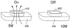
図3は、異種の負荷に電力を同時に送信する例を示す図である。
図3を参照すると、ターゲット装置310はソース共振部330に隣接するターゲット装置であり、ターゲット装置320はソース共振部340に隣接するターゲット装置である。
すなわち、ソース共振部330及びソース共振部340がパッド形態である場合、ターゲット装置310はソース共振部330上に置かれ、ターゲット装置320はソース共振部340上に置かれる。3 to 7 are diagrams illustrating an example of multi-target charging according to an embodiment of the present invention.
FIG. 3 is a diagram illustrating an example in which power is simultaneously transmitted to different types of loads.
Referring to FIG. 3, the
That is, when the
図3に示した例として、ターゲット装置310は5ワットの電力が必要であり、ターゲット装置320は10ワットの電力が必要である。
すなわち、無線電力送信装置がターゲット装置310に送信する電力は5ワットであり、無線電力送信装置がターゲット装置320に送信する電力は10ワットである。
ここで、ターゲット装置310は、ターゲット装置320に比べて「低電力デバイス又は低電力負荷」と称する。「低電力」は10Wよりも小さい電力要求を示し、ターゲット装置320は「高電力デバイス又は高電力負荷」と称する。「高電力」は10W以上である電力要求を示す。このように、負荷又はターゲット装置の種類はターゲット装置で必要な電力に応じて分類される。As an example shown in FIG. 3, the
That is,the power of the wireless power transmission device transmits to the
Here, the
図3でソース共振部330及びソース共振部340は無線電力送信装置に備えられる。
無線電力送信装置の具体的な構成例は図8を参照して詳細に説明することとする。
本発明の一実施形態によると、無線電力送信装置は、低電力デバイスと高電力デバイスに同時に電力を送信する場合、高電力デバイスに隣接するソース共振部340をオンにし、低電力デバイスに隣接するソース共振部330はオフにする。In FIG. 3, the
A specific configuration example of the wireless power transmission apparatus will be described in detail with reference to FIG.
According to an embodiment of the present invention, when transmitting power to a low power device and a high power device at the same time, the wireless power transmission apparatus turns on the
図3に示した例として、ターゲット装置320はソース共振部340から電力を無線で受信し、ターゲット装置310はターゲット装置320から電力を受信する。
すなわち、ターゲット装置310は、カップリング1のような電磁結合によってターゲット装置320から電力を受信する。また、実施形態によりターゲット装置310は、カップリング2のような電磁結合によってソース共振部340から電力を受信してもよい。As an example illustrated in FIG. 3, the
That is, the
一方、図3に示した例として、ターゲット装置310の共振器である第1ターゲット共振器(図示せず)及びターゲット装置320の共振器である第2ターゲット共振器(図示せず)は、サイズ又はコイルの巻数が互いに異なる。
例えば、ターゲット装置310の第1ターゲット共振器はターゲット共振器320の第2ターゲット共振器よりもそのサイズが1.1〜2倍以上大きくてもよい。On the other hand, as an example shown in FIG. 3, a first target resonator (not shown) that is a resonator of the
For example, the first target resonator of the
図4は、高電力デバイスの電力受信が終了した場合の例を示す図である。
図4を参照すると、ターゲット装置410はソース共振部430に隣接するターゲット装置であり、ターゲット装置420はソース共振部440に隣接するターゲット装置である。すなわち、ソース共振部430及びソース共振部440がパッド形態である場合、ターゲット装置410はソース共振部430上に置かれ、ターゲット装置420はソース共振部440上に置かれる。一実施形態において、ターゲット装置は、ソース共振部の隣りに置かれているものと認識されてもよい。FIG. 4 is a diagram illustrating an example when the power reception of the high power device is completed.
Referring to FIG. 4, the
図4に示した例として、高電力デバイスのターゲット装置420の電力受信が終了すると、ソース共振部440はターンオフされてソース共振部430はターンオンされる。
したがって、ターゲット装置410はソース共振部430から電力を受信する。
ここで、ターゲット装置420の電力受信が終了した場合とは、例えば、ターゲット装置420がソース共振部440から10ワットの電力を全て受信した場合であってもよい。無線電力送信装置は反射波を検出したり、ターゲット装置からメッセージを受信することによってターゲット装置420の電力受信が終了したことが分かる。In the example illustrated in FIG. 4, when the power reception of the
Therefore, the
Here, the case where the power reception of the
図5は、低電力デバイスの電力受信が終了した場合の例を示す図である。
図5を参照すると、ターゲット装置510はソース共振部530に隣接するターゲット装置であり、ターゲット装置520はソース共振部540に隣接するターゲット装置である。すなわち、ソース共振部530及びソース共振部540がパッド形態である場合、ターゲット装置510はソース共振部530上に置かれ、ターゲット装置520はソース共振部540上に置かれる。一実施形態において、ターゲット装置は、ソース共振部の隣りに置かれているものと認識されてもよい。FIG. 5 is a diagram illustrating an example when the power reception of the low-power device is completed.
Referring to FIG. 5, the
図5に示した例として、低電力デバイスのターゲット装置510の電力受信が終了すると、ターゲット装置510は負荷との接続を切断させる。ターゲット装置510が負荷との接続を切断させると、ターゲット装置510とターゲット装置520との間の電磁結合は形成されない。 As an example shown in FIG. 5, when the power reception of the
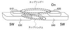
図6は、同一の種類の負荷に電力を同時に送信する例を示す図である。
図6を参照すると、ターゲット装置610はソース共振部630に隣接するターゲット装置であり、ターゲット装置620はソース共振部640に隣接するターゲット装置である。すなわち、ソース共振部630及びソース共振部640がパッド形態である場合、ターゲット装置610はソース共振部630上に置かれ、ターゲット装置620はソース共振部640上に置かれる。一実施形態において、ターゲット装置は、ソース共振部の隣りに置かれているものと認識されてもよい。FIG. 6 is a diagram illustrating an example in which power is simultaneously transmitted to the same type of load.
Referring to FIG. 6, the
図6に示した例として、ターゲット装置610及びターゲット装置620は全て低電力デバイスである。
もちろん、図6に示したものとは相違して、ターゲット装置610及びターゲット装置620は全て高電力デバイスであってもよい。
一実施形態で、ターゲット装置610に送信する電力「P1」とターゲット装置620に送信する電力「P2」の差が予め設定された範囲内である場合、ターゲット装置610及びターゲット装置620は同じ種類の負荷に分類される。例えば、「P1」と「P2」の差が2ワット以下である場合、ターゲット装置610及びターゲット装置620は同じ種類の負荷に分類されてもよい。In the example shown in FIG. 6, the
Of course, unlike the one shown in FIG. 6, the
In one embodiment, when the difference between thepower “P1” transmitted to the
負荷の種類が同一である場合、カップリングファクター又は電力送信効率が考慮され得る。すなわち、無線電力送信装置はターゲット装置610及びターゲット装置620それぞれに対するカップリングファクターを確認し、ソース共振部610及びソース共振部620のうちカップリングファクターが大きいソース共振部を選択する。
ここで、カップリングファクターが大きいソース共振部はターンオンされ、カップリングファクターが小さいソース共振部はターンオフされる。If the type of load is the same, the coupling factor or power transmission efficiency can be considered. That is, the wireless power transmission device confirms the coupling factor for each of the
Here, the source resonator having a large coupling factor is turned on, and the source resonator having a small coupling factor is turned off.
図6に示す例として、「ターゲット装置620とソース共振部640との間のカップリングファクター」は「ターゲット装置610とソース共振部630との間のカップリングファクター」よりも大きい。
したがって、ソース共振部640はターンオンされ、ソース共振部630はターンオフされる。
ターゲット装置610はカップリング1のような電磁結合によってターゲット装置620から電力を受信する。また、実施形態に係るターゲット装置610は、カップリング2のような電磁結合によってソース共振部640から電力を受信してもよい。As an example shown in FIG. 6, “the coupling factor between the
Accordingly, the
The
無線電力送信装置は、反射電力を測定したり、ターゲット装置(610、620)それぞれから電力送信効率に関する情報を受信することで、ターゲット装置(610、620)それぞれに対する電力送信効率を把握することができる。
無線電力送信装置は、ソース共振部630及びソース共振部640のうち電力送信効率が優れるソース共振部を選択する。The wireless power transmission device can grasp the power transmission efficiency for each of the target devices (610, 620) by measuring the reflected power or receiving information on the power transmission efficiency from each of the target devices (610, 620). it can.
The wireless power transmission device selects a source resonance unit having excellent power transmission efficiency among the
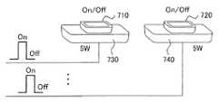
図7は、同一の種類の負荷に電力を順次送信する例を示す図である。
図7を参照すると、ターゲット装置710はソース共振部730に隣接するターゲット装置であり、ターゲット装置720はソース共振部740に隣接するターゲット装置である。すなわち、ソース共振部730及びソース共振部740がパッド形態である場合、ターゲット装置710はソース共振部730上に置かれ、ターゲット装置720はソース共振部740上に置かれる。一実施形態において、ターゲット装置は、ソース共振部の隣りに置かれているものと認識されてもよい。
ソース共振部730及びソース共振部740は、交互にターンオン又はターンオフすることで、ターゲット装置710及びターゲット装置720に同じ量の電力を送信することができる。FIG. 7 is a diagram illustrating an example in which power is sequentially transmitted to the same type of load.
Referring to FIG. 7, the
The
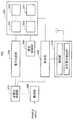
図8は、本発明の一実施形態に係る無線電力送信装置の構成を示すブロック図である。
図8を参照すると、無線電力送信装置800は、検出部810、制御部820、及び電力送信部830を備える。
また、無線電力送信装置800は、電力生成部840、整合制御部850、整流部860、及び定電圧制御部870をさらに備えてもよい。FIG. 8 is a block diagram showing a configuration of a wireless power transmission apparatus according to an embodiment of the present invention.
Referring to FIG. 8, the wireless
In addition, the wireless
検出部810は、電力を無線で受信する複数のターゲット装置を検出する。
検出部810は、ウェイクアップリクエスト信号をブロードキャストし、複数のターゲット装置それぞれからウェイクアップリクエスト信号に応答する応答信号を受信する通信部を備える。
また、検出部810は、反射電力を検出する反射電力検出部をさらに備えてもよい。The
The
The
ここで、応答信号それぞれは、当該ターゲット装置の識別子情報及び当該ターゲット装置で用いられる電力に関する情報を含んでもよい。
検出部810は、複数のターゲット装置から複数のターゲット装置それぞれの位置情報を受信する。
ここで、複数のターゲット装置それぞれの位置情報は、ソース共振部(831、833、835、837)それぞれの識別子情報であってもよい。Here, each response signal may include identifier information of the target device and information related topower used in the target device.
The
Here, the position information of each of the plurality of target devices may be identifier information of each of the source resonance units (831, 833, 835, 837).
例えば、ソース共振部831に隣接する第1ターゲット装置は、ソース共振部831からソース共振部831の識別子「S1」を受信し、受信された「S1」をウェイクアップリクエスト信号に対する応答信号に含ませて検出部810に送信する。
ここで、ソース共振部831がパッド形態である場合、ソース共振部831上に置かれたターゲット装置はソース共振部831に隣接する第1ターゲット装置と称する。
一方、ソース共振部831上に2つのターゲット装置が置かれる場合、「当該ターゲット装置で用いられる電力」は2つのターゲット装置それぞれで用いられる電力を和した値であってもよい。For example, the first target device adjacent to the
Here, when the
On the other hand, when two target devices are placed on the
電力送信部830は、複数のソース共振部(831、833、835、837)を含む。
ここで、複数のソース共振部(831、833、835、837)のそれぞれは、アレイ状に配列される複数の共振器を含んでもよい。
下記の説明において、ソース共振部831に隣接するターゲット装置を第1ターゲット装置と称し、ソース共振部833に隣接するターゲット装置を第2ターゲット装置と称する。The
Here, each of the plurality of source resonance units (831, 833, 835, 837) may include a plurality of resonators arranged in an array.
In the following description, a target device adjacent to the
制御部820は、「複数のターゲット装置のうち1つ以上に送信する電力」または「複数のターゲット装置のうち1つ以上に対するカップリングファクター」に基づいて、複数のデバイスそれぞれに隣接する複数のソース共振部(831、833、835、837)のいずれか1つのソース共振部を選択する。
ここで、電力送信部830は、制御部820の制御に応じて選択されたソース共振部と選択されたソース共振部に隣接するターゲット装置のターゲット共振器間の電磁結合によって選択されたソース共振部に隣接するターゲット装置に電力を無線送信する。The
Here, the
制御部820は、複数のソース共振部(831、833、835、837)の内の複数のターゲット装置の内の1つ以上に送信する電力が大きいソース共振部、又は複数のターゲット装置の内の1つ以上に対するカップリングファクターが大きいソース共振部を選択する。
ここで、制御部820は、選択されたソース共振部をターンオンさせ、選択されたソース共振部以外のソース共振部をターンオフさせる。The
Here, the
制御部820は「ソース共振部831に隣接する第1ターゲット装置に送信する電力P1」と「ソース共振部833に隣接する第2ターゲット装置に送信する電力P2」を確認する第1プロセッサを含んでもよい。
また、制御部820は、第2プロセッサを含んでもよい。第2プロセッサは「P2」より「P1」が予め設定された値よりも大きければ、ソース共振部831を選択する。
ここで、予め設定された値は、1〜200ワットなどの様々な値に設定されてもよい。The
The
Here, the preset value may be set to various values such as 1 to 200 watts.
また、第2プロセッサは、「P1」より「P2」が予め設定された値よりも大きければ、ソース共振部833を選択する。
図3〜図5に示した例は、予め設定された値が4ワットであり、「P1」と「P2」の差が4ワットよりも大きい場合である。
また、第2プロセッサは、「P1」と「P2」との差が設定された値以下であれば、第1及び第2ターゲット装置それぞれに対するカップリングファクターを確認してソース共振部831及びソース共振部833のうちカップリングファクターが大きいソース共振部を選択する。Further, the second processor selects the
The example shown in FIGS. 3 to 5 is a case where the preset value is 4 watts and the difference between “P1” and “P2” is larger than 4 watts.
In addition, if the difference between “P1” and “P2” is equal to or less than the set value, the second processor confirms the coupling factor for each of the first and second target devices and checks the
図6、図7に示した例は、予め設定された値が1ワットであり、「P1」と「P2」との差が1ワットよりも小さい場合である。
したがって、第2プロセッサは図7に示すように、「P1」と「P2」との差が予め設定された値以下であれば、ソース共振部831及びソース共振部833を交互にターンオン/オフする。The example shown in FIGS. 6 and 7 is a case where the preset value is 1 watt and the difference between “P1” and “P2” is smaller than 1 watt.
Therefore, as shown in FIG. 7, the second processor alternately turns on / off the
制御部820は、選択されたソース共振部831に隣接する第1ターゲット装置の電力受信が終了すると、選択されたソース共振部831をターンオフさせ、複数のソース共振部(833、835、837)のうち電磁結合によってターゲット共振器から電力を無線で受信する低電力デバイスに隣接するソース共振部833をターンオンさせる。
すなわち、図4に示すように、制御部820は選択されたソース共振部831をターンオフさせ、低電力デバイス410に隣接するソース共振部833をターンオンにする。
ここで、図4に示すソース共振部440は図8に示すソース共振部831であり、図4に示すソース共振部430は図8に示すソース共振部833であると仮定する。When the power reception of the first target device adjacent to the selected
That is, as shown in FIG. 4, the
Here, it is assumed that the
制御部820は、電力生成部840を制御し、ソース共振部(831、833、835、837)それぞれを介して送信される電力を制御する。
したがって、制御部820は、選択されたソース共振部831に隣接する第1ターゲット装置で用いられる電力「PHIGH」及び低電力デバイスで用いられる電力「PLOW」に基づいて、選択されたソース共振部831から選択されたソース共振部831に隣接する第1ターゲット装置に無線送信される電力を決定する。
ここで、第1ターゲット装置は高電力デバイスであり、第2ターゲット装置は低電力デバイスであると仮定する。The
Therefore, the
Here, it is assumed that the first target device is a high power device and the second target device is a low power device.
図3に示すように、制御部820の制御に応じて電力生成部840は、ターゲット装置320からターゲット装置310に電磁結合によって送信される電力に基づいて電力を生成する。
ここで、「PHIGH」及び「PLOW」に基づくということは、第1ターゲット装置に送信される電力が最小限「PHIGH」よりも大きいことを意味する。
「PHIGH」と「PLOW」との差が大きいほど、第1ターゲット装置と第2ターゲット装置との間の電磁結合が順調に形成され得る。
したがって、「PHIGH」と「PLOW」との差が極めて大きい場合(例えば10ワット以上)には「PHIGH」と「PLOW」との差が小さい場合(例えば5ワット以下)に比べて電力送信の効率がより優れる。As illustrated in FIG. 3, the
Here, being based on “PHIGH ” and “PLOW ” means that thepower transmitted to the first target device is at least larger than “PHIGH ”.
The larger the difference between “PHIGH ” and “PLOW ”, the more smoothly the electromagnetic coupling between the first target device and the second target device can be formed.
Therefore, when the difference between “PHIGH ” and “PLOW ” is extremely large (for example, 10 watts or more), the difference between “PHIGH ” and “PLOW ” is small (for example, 5 watts or less). More efficient power transmission.
制御部820は、低電力デバイスの電力受信が終了すると、「選択されたソース共振部831に隣接する第1ターゲット装置で用いられる電力」及び「選択されたソース共振部833に隣接する第1ターゲット装置に受信された電力」に基づいて、選択されたソース共振部833に隣接する第2ターゲット装置に無線送信される電力を制御する。When the power reception of the low-power device is completed, the
電力生成部840は、無線電力受信装置に送信される電力を生成する。
電力生成部840は、制御部820の制御により電力を生成する。電力生成部840は、数MHz〜数十MHz帯域のスイッチングパルス信号によって一定レベルのDC電流をAC電流に変換することで電力を生成する。
したがって、電力生成部840は、AC/DCインバータを含んで構成される。ここで、一定レベルのDC電流は、定電圧制御部870から提供される。AC/DCインバータは、高速スイッチングのためのスイッチング素子を含む。ここで、スイッチング素子は、スイッチングパルス信号が「high」のときパワーオンされ、スイッチングパルス信号が「Low」のときパワーオフされるよう構成される。The
The
Therefore, the
整合制御部850は、電力送信部830と電力生成部840との間のインピーダンス整合を行う。
すなわち、整合制御部850は、制御部820の制御により複数のソース共振部(831、833、835、837)のインピーダンスを調整する。
整流部860は、数十Hz帯域のAC電圧を整流してDC電圧を生成する。
定電圧制御部870は、整流部860からDC電圧の入力を受け、制御部820の制御により一定レベルのDC電圧を出力する。定電圧制御部870は一定レベルのDC電圧を出力するための安定化した回路を含んで構成される。The matching
That is, the matching
The rectifying
The constant
図9は、図8の電力送信部の構成例を示す図である。
図9を参照すると、電力送信部830は、4個のソース共振部(910、920、930、940)を備える。
4個のソース共振部(910、920、930、940)のそれぞれは、1つの共振器で構成されるか、又は、図10に示すようにアレイで構成されてもよい。FIG. 9 is a diagram illustrating a configuration example of the power transmission unit in FIG. 8.
Referring to FIG. 9, the
Each of the four source resonators (910, 920, 930, 940) may be formed of one resonator, or may be formed of an array as shown in FIG.
図9を参照すると、ソース共振部910でウェイクアップ信号がターゲット装置960に送信された後、ウェイクアップ信号に対する応答信号によってターゲット装置960が検出される。
ここで、ソース共振部910からターゲット装置960に送信されるウェイクアップ信号はソース共振部910の識別子情報を含む。Referring to FIG. 9, after a wakeup signal is transmitted to the
Here, the wakeup signal transmitted from the
すなわち、図8に示す通信部は、データ通信のために割り当てられた周波数を用いてアウト−バンド通信を行い、電力送信部830は「共振周波数を使用してターゲット装置とデータを送受信するイン−バンド通信」を行う。したがって、ウェイクアップ信号に対する応答信号は、イン−バンド通信によって無線電力送信装置800に受信されるか、又はアウト−バンド通信によって無線電力送信装置800に受信される。 That is, the communication unit illustrated in FIG. 8 performs out-band communication using a frequency allocated for data communication, and the
一方、一定時間中にウェイクアップ信号に対する応答信号がなければ、次のソース共振器920にスイッチングしてもよい。
ソース共振器920は、ウェイクアップ信号を送信し、一定時間中にウェイクアップ信号に対する応答信号がなければ、状態をオフ状態に保持する。
上記のような方式でソース共振器(930、940)でターゲット装置970の検出工程が行われる。On the other hand, if there is no response signal for the wake-up signal within a certain time, switching to the
The
The detection process of the
このように、ソース共振部(910、920、930、940)が順次ターンオン/オフされてウェイクアップ信号をブロードキャストすることによって、どのようなソース共振部にターゲット装置が隣接しているかを検出することができる。
ソース共振部(910、920、930、940)のそれぞれはソース共振部識別子によって区分される。
ここで、図8に示す制御部820は、ソース共振部(910、920、930、940)のそれぞれのソース共振部識別子を用いて複数のデバイスそれぞれの位置を認識することもある。In this manner, the source resonator unit (910, 920, 930, 940) is sequentially turned on / off and broadcasts a wake-up signal, thereby detecting which source resonator unit is adjacent to the target resonator unit. Can do.
Each of the source resonators (910, 920, 930, 940) is distinguished by a source resonator identifier.
Here, the
図10は、図9のソース共振部の構成例を示す図である。
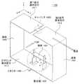
図10に示すように、ソース共振部910又は図8のソース共振部831は、アレイ状に配列される4つ以上のソース共振器(911、913、915、917)を含み得る。
また、図10に示したものとは異なり、ソース共振部910又は図8のソース共振部831は1つのソース共振器で構成してもよい。FIG. 10 is a diagram illustrating a configuration example of the source resonance unit in FIG. 9.
As shown in FIG. 10, the
Further, unlike the one shown in FIG. 10, the
図11は、本発明の一実施形態に係る無線電力受信装置の構成を示すブロック図である。
図11を参照すると、無線電力受信装置1100は、通信部1110、電力受信部1120、及び制御部1130を備える。
また、無線電力受信装置1100は、電力供給部1150及び負荷経路スイッチ1140をさらに備えてもよい。FIG. 11 is a block diagram showing a configuration of a wireless power receiving apparatus according to an embodiment of the present invention.
Referring to FIG. 11, the wireless
The wireless
通信部1110は、図8の無線電力送信装置800からウェイクアップリクエスト信号を受信し、ウェイクアップリクエスト信号に対する応答信号を無線電力送信装置800に送信する。
ここで、応答信号は「無線電力受信装置の識別子情報」、「隣接するソース共振部から受信されたソース共振部識別子情報」及び「前記無線電力受信装置で用いられる電力に関する情報」を含んでもよい。The
Here, the response signal may include “identifier information of the wireless power receiver”, “source resonator identifier information received from an adjacent source resonator”, and “information aboutpower used in the wireless power receiver”. .
また、通信部1110は、イン−バンド通信によって隣接するソース共振部からソース共振部識別子情報を受信し、アウト−バンド通信によってソース共振部識別子情報を無線電力送信装置800に送信することもある。
ここで、「インバンド」通信とは、電力送信に使用される同じ周波数帯域及び/又は同じチャネルで送信される情報(例えば、制御情報、データ及び/又はメタデータ)の通信を意味する。「アウトバンド」通信とは、別個の周波数帯域で送信される情報及び/又は電力送信のために分離された、又は専用(dedicated)チャネルを使用する情報を意味する。In addition, the
Here, “in-band” communication means communication of information (for example, control information, data, and / or metadata) transmitted in the same frequency band and / or the same channel used for power transmission. “Out-band” communication refers to information transmitted in a separate frequency band and / or information using a separate or dedicated channel for power transmission.
電力受信部1120は、ソース共振部から無線で電力を受信し、他の無線電力受信装置のターゲット共振器「T_other」と電磁結合を形成し、ターゲット共振器「T_other」から無線で電力を受信する。
電力受信部1120は、無線電力受信装置1100で用いられる電力が他の無線電力受信装置で用いられる電力よりも大きければ、ソース共振部から無線で電力を受信する。そして、電力受信部1120は、無線電力受信装置で用いられる電力が他の無線電力受信装置で用いられる電力よりも小さければ、ターゲット共振器「T_other」から無線で電力を受信する。The power receiver 1120 wirelessly receives power from the source resonator, forms electromagnetic coupling with the target resonator “T_other” of another wireless power receiver, and receives power wirelessly from the target resonator “T_other”. .
Power receiver 1120,power used by the
電力受信部1120は、共振器1121、共振スイッチ1123、及び整合制御部1125を備える。
共振器1121は、図1のターゲット共振器121と同じ機能を行う。
共振スイッチ1123は、制御部1130の制御によりターンオン/オフされる。
整合制御部1125は、「共振器1121と負荷1160との間」又は「無線電力送信装置800と共振器1121との間」のインピーダンス整合を行う。The power receiving unit 1120 includes a
The
The
The matching
整合制御部1125は、反射波を検出するか、又は負荷のインピーダンス変化を検出することによって、インピーダンス整合の実行可否を判断する。
ここで、共振器1121は、他の無線電力受信装置のターゲット共振器「T_other」とサイズ又はコイルの巻数が異なってもよい。ここで、コイルの巻数は、共振器がコイル形態である場合にコイルの巻回された回数を意味する。The matching
Here, the
制御部1130は、電力受信が終了すれば負荷1160の接続をターンオフさせる。
すなわち、制御部1130は、電力受信が終了すれば負荷経路スイッチ1140をターンオフさせる。
負荷経路スイッチ1140がターンオフされると、共振器1121はソース共振器と電磁結合を形成することができない。ここで、負荷1160はバッテリであってもよく、電力を消費する回路、又は無線電力受信装置1100に取付け可能な外部装置であってもよい。The
That is, the
When the load path switch 1140 is turned off, the
制御部1130は、無線電力送信装置800から無線で受信される電力の電力送信効率を算出する。
無線電力送信装置800が送信電力「Pt」をブロードキャストすると、制御部1130は「Pt」と受信電力「Pr」の比率を算出することによって電力送信効率を算出する。
制御部1130は、電力送信効率を周期的に算出し、通信部1110によって電力送信効率に関する情報を無線電力送信装置800に送信する。
また、制御部1130は負荷1160の状態をチェックし、負荷1160へのチャージングが完了すれば、負荷1160へのチャージが完了したことを無線電力送信装置800に知らせる。The
When the wireless
The
In addition, the
電力供給部1150は、無線電力送信装置800から無線で受信される電力を負荷1160に提供する。
電力供給部1150は、交流電圧を整流することによってDC電圧を生成する整流部1151及び整流部1151から出力されるDC電圧のレベルを調整し、負荷1160で必要なDC電圧を生成するDC/DCコンバータ1153を含む。The
The
図12は、本発明の一実施形態に係る無線電力送信の制御方法を説明するための図である。
図12に示す例として、第1無線電力受信装置1210は高電力負荷であり、第2無線電力受信装置1220は低電力負荷である。FIG. 12 is a diagram for explaining a method for controlling wireless power transmission according to an embodiment of the present invention.
As an example illustrated in FIG. 12, the first
図12を参照すると、ステップ1201において、ソース共振部831はウェイクアップ信号をブロードキャストする。
ソース共振部831でブロードキャストされたウェイクアップ信号は第1無線電力受信装置1210に受信される。予め設定された時間区間T1内に第1無線電力受信装置1210から応答信号が受信されると、無線電力送信装置800は第1無線電力受信装置を検出する。また、無線電力送信装置800は、第1無線電力受信装置がソース共振部831のカバレッジ内に位置していることが分かる。
ここで、応答信号は、第1無線電力受信装置1210で用いられる電力に関する情報及び第1無線電力受信装置1210の識別子情報を含む。Referring to FIG. 12, in
The wakeup signal broadcast by the
Here, the response signal includes information on thepower used by the first
ステップ1203において、ソース共振部835は、ウェイクアップ信号をブロードキャストする。
ソース共振部835でブロードキャストされたウェイクアップ信号は第2無線電力受信装置1220に受信される。予め設定された時間区間T2内に第2無線電力受信装置1220から応答信号が受信されると、無線電力送信装置800は第2無線電力受信装置を検出する。また、無線電力送信装置800は、第2無線電力受信装置がソース共振部835のカバレッジ内に位置していることが分かる。
ここで、応答信号は、第2無線電力受信装置1220で用いられる電力に関する情報及び第2無線電力受信装置1220の識別子情報を含む。
In
The wakeup signal broadcast by the
Here, the response signal includes information onpower used in the second
ステップ1201及びステップ1203によって、無線電力送信装置800は電力を無線で受信する複数のターゲット装置を検出する。
すなわち、ステップ1201及びステップ1203は、複数のターゲット装置を検出するステップである。したがって、ステップ1201及びステップ1203で無線電力送信装置800は、複数のソース共振部を用いてウェイクアップリクエスト信号を順次ブロードキャストし、複数のターゲット装置からウェイクアップリクエスト信号に対する応答信号を順次受信する。Through
That is,
一方、アウト−バンド通信によってターゲット装置を検出する場合、無線電力送信装置800の検出部810は、ステップ1205及びステップ1207でウェイクアップ信号をブロードキャストする。
第1及び第2無線電力受信装置(1210、1220)は、ステップ1209及びステップ1211で応答信号を無線電力送信装置800に送信する。
無線電力送信装置800は、高電力負荷に隣接するソース共振部831を選択し、ステップ1213においてソース共振部831によって第1無線電力受信装置1210に電力を送信する。
ステップ1215において、第2無線電力受信装置1220は第1無線電力受信装置1210と電磁結合を形成し、第1無線電力受信装置1210から電力を受信する。On the other hand, when the target device is detected by out-band communication, the
The first and second wireless power receivers (1210, 1220) transmit response signals to the
The wireless
In
一方、ソース共振器及び/又はターゲット共振器は、ヘリックス(helix)コイル構造の共振器、又は、スパイラル(spiral)コイル構造の共振器、又は「meta−structured」共振器から構成されてもよい。 On the other hand, the source resonator and / or the target resonator may be a resonator having a helix coil structure, a resonator having a spiral coil structure, or a “meta-structured” resonator.
すでに公知の内容であるが、理解の便利のために関連用語について記述する。
全ての物質は固有の透磁率(Mu)及び誘電率(epsilon)を有する。透磁率は該当物質で与えられた磁界(magnetic field)に対して発生する磁束密度(magnetic flux density)と真空中でその磁界に対して発生する磁束密度の比を意味する。そして、誘電率は、該当物質で与えられた電界(electric field)に対して発生する電束密度(electric flux density)と真空中でその電界に対して発生する電束密度の比を意味する。
透磁率及び誘電率は与えられた周波数又は波長で該当物質の伝搬定数を決定し、透磁率及び誘電率によってその物質の電磁気特性が決定される。
特に、自然界に存在しない誘電率又は透磁率を有し、人工的に設計された物質をメタ物質といい、メタ物質は極めて大きい波長又は極めて低い周波数領域でも簡単に(すなわち、物質のサイズが多く変わらなくても)共振状態に置かれ得る。Although it is already known, related terms are described for convenience of understanding.
All materials have inherent magnetic permeability (Mu) and dielectric constant (epsilon). The magnetic permeability means a ratio between a magnetic flux density generated with respect to a magnetic field given by a corresponding material and a magnetic flux density generated with respect to the magnetic field in a vacuum. The dielectric constant means a ratio between an electric flux density generated with respect to an electric field given by a corresponding material and an electric flux density generated with respect to the electric field in vacuum.
The permeability and dielectric constant determine the propagation constant of the substance at a given frequency or wavelength, and the electromagnetic characteristics of the substance are determined by the permeability and dielectric constant.
In particular, an artificially designed material that has a dielectric constant or permeability that does not exist in nature is called a metamaterial, and it can be easily used at very large wavelengths or very low frequency ranges (ie, the size of the material is large). (Even if not changed) can be placed in resonance.
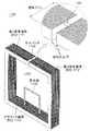
図13〜図20は、本発明での共振器の実施形態を示す。
図13は、本発明の一実施形態に係る2次元(平面)構造の共振器を示す図である。
図13を参照すると、本発明の一実施形態に係る2次元構造(平面)の共振器は、第1信号導体部分1311、第2信号導体部分1312、及びグラウンド導体部分1313を含む送信線路、キャパシタ1320、整合器1330、及び導体(1341、1342)を備える。13 to 20 show an embodiment of a resonator according to the present invention.
FIG. 13 is a diagram illustrating a resonator having a two-dimensional (planar) structure according to an embodiment of the present invention.
Referring to FIG. 13, a resonator having a two-dimensional structure (planar) according to an embodiment of the present invention includes a transmission line and a capacitor including a first
図13に示すように、キャパシタ1320は、送信線路で第1信号導体部分1311と第2信号導体部分1312との間に位置に直列に挿入され、それによって電界はキャパシタ1320に閉じ込められるようになる。一般的に、送信線路は上部に少なくとも1つの導体、下部に少なくとも1つの導体を含み、上部にある導体を介して電流が流れ、下部にある導体は電気的にグラウンドされる。
本明細書では送信線路の上部にある導体を、第1信号導体の部分1311と第2信号導体の部分1312に分類して呼び、送信線路の下部にある導体をグラウンド導体部分1313と呼ぶ。As shown in FIG. 13, the capacitor 1320 is inserted in series between the first
In this specification, the conductor at the upper part of the transmission line is classified and called as a first
図13に示すように、本発明の一実施形態に係る共振器1300は、2次元(平面)構造の形態を有する。
送信線路路は、上部に第1信号導体部分1311及び第2信号導体部分1312を含み、下部にグラウンド導体部分1313を含む。
第1信号導体部分1311及び第2信号導体部分1312とグラウンド導体部分1313は互いに向かい合うように配置される。電流は第1信号導体部分1311及び第2信号導体部分1312を通じて流れる。As shown in FIG. 13, a
The transmission line path includes a first
The first
また、図13に示すように、第1信号導体部分1311の一端は導体1342と接続され、他端はキャパシタ1320と接続される。そして、第2信号導体部分1312の一端は導体1341と接続され、他端はキャパシタ1320と接続される。
すなわち、第1信号導体部分1311、第2信号導体部分1312、及びグラウンド導体部分1313、導体(1341、1342)は互いに接続されることによって、共振器1300は電気的に閉じたループ構造を有する。ここで、「閉じたループ構造」は、円形構造、四角形のような多角形の構造などを含む。As shown in FIG. 13, one end of the first
That is, the first
キャパシタ1320は送信線路の中部に挿入される。
他えば、キャパシタ1320は第1信号導体部分1311と第2信号導体部分1312との間に挿入される。ここで、キャパシタ1320は、集中素子(lumped element)及び分散素子(distributed element)などの形態を有してもよい。特に、分散素子の形態を有する分散したキャパシタは、ジグザグ形態の導体ラインとその導体ラインとの間に存在する高い誘電率を有する誘電体を含む。The capacitor 1320 is inserted in the middle of the transmission line.
In other words, the capacitor 1320 is inserted between the first
キャパシタ1320が送信線路に挿入されることによって共振器1300はメタ物質の特性を有し得る。
ここで、メタ物質とは自然で発見されない特別な電気的な性質を有する物質として、人工的に設計された構造を有する。自然界で存在する全ての物質は正の透磁率または正の誘電率を有する。大部分の物質で電気場、磁場及びポインティングベクトルに対して右手の法則が適用され、このような物質をRHM(Right Handed Material)という。
しかし、メタ物質は、自然界で存在しない誘電率又は透磁率を有する物質として、誘電率または透磁率の符号によってENG(epsilon negative)物質、MNG(mu negative)物質、DNG(double negative)物質、NRI(negative refractive index)物質、LH(left−handed)物質などに分類される。By inserting the capacitor 1320 into the transmission line, the
Here, the metamaterial has a structure artificially designed as a material having a special electrical property that is not found in nature. All materials present in nature have a positive permeability or a positive dielectric constant. For most materials, the right-hand rule is applied to the electric field, magnetic field, and pointing vector, and such materials are called RHM (Right Handed Material).
However, the meta material is a material having a dielectric constant or magnetic permeability that does not exist in nature, and is an ENG (epsilon negative) material, an MNG (mu negative) material, a DNG (double negative) material, an NRI, depending on the sign of the dielectric constant or magnetic permeability. (Negative reflective index) substance, LH (left-handed) substance, etc.
ここで、集中素子として挿入されたキャパシタ1320のキャパシタンスを適切に調整することによって共振器1300はメタ物質の特性を有し得る。
特に、キャパシタ1320のキャパシタンスを適切に調整することによって、共振器は負の透磁率を有しえるため、本発明の一実施形態に係る共振器1300はMNG共振器と呼ばれる。
後述にて説明するが、キャパシタ1320のキャパシタンスを定める前提(criterion)は様々であり得る。共振器1300がメタ物質の特性を有する前提、共振器1300が対象周波数で負の透磁率を有する前提、共振器1300が対象周波数で零次共振(Zeroth−Order Resonance)の特性を有する前提などがあり、前述した前提のうち少なくとも一つ以上の前提下でキャパシタ1320のキャパシタンスが決定されてもよい。Here, by appropriately adjusting the capacitance of the capacitor 1320 inserted as a lumped element, the
In particular, the
As will be described later, the assumptions that determine the capacitance of capacitor 1320 can vary. The assumption that the
(MNG)共振器1300は、伝搬定数が0であるときの周波数を共振周波数として有する零次共振の特性を有する。
(MNG)共振器1300は、零次共振特性を有するため、共振周波数は(MNG)共振器1300の物理的なサイズに対して独立的であり得る。すなわち、下記で再び説明するが、(MNG)共振器1300で共振周波数を変更するためにはキャパシタ1320を適切に設計することで充分であるため、(MNG)共振器1300の物理的なサイズを変更しなくてもよい。The (MNG)
Since the (MNG)
また、近接フィールドにおいて、電界は送信線路に挿入されたキャパシタ1320に集中するため、キャパシタ1320によって近接フィールドでは磁界がドミナント(dominant)される。そして、(MNG)共振器1300は集中素子のキャパシタ1320を用いて高いQ−ファクター(Q−Factor)を有するため、電力送信の効率を向上させることができる。参考に、Q−ファクターは、無線電力送信において、抵抗損失の程度、又は抵抗に対するリアクタンスの比を表すが、Q−ファクターが大きいほど無線電力送信の効率は大きいものと理解される。 In addition, since the electric field concentrates on the capacitor 1320 inserted in the transmission line in the near field, the magnetic field is dominant in the near field by the capacitor 1320. Since the (MNG)
また、(MNG)共振器1300はインピーダンス整合のための整合器1330を備えてもよい。ここで、整合器1330は、(MNG)共振器1300の磁界の強度を適切に調整することができ、整合器1330により(MNG)共振器1300のインピーダンスが決定される。
そして、電流はコネクタを介して(MNG)共振器1300に流入するか、(MNG)共振器1300から流出する。ここで、コネクタはグラウンド導体部分1313又は整合器1330と接続される。ただし、コネクタとグラウンド導体部分1313又は整合器1330の間には物理的な連結が形成されてもよく、コネクタとグラウンド導体部分1313又は整合器1330の間に物理的な連結なしでカップリングを介して電力が伝達されてもよい。Further, the (MNG)
Then, the current flows into the (MNG)
詳細には、図13に示すように、整合器1330は、共振器1300のループ構造によって形成されるループ内に位置する。整合器1330は、物理的な形態を変更することによって共振器1300のインピーダンスを調整する。
特に、整合器1330は、グラウンド導体部分1313から距離「h」だけ離れた位置にインピーダンス整合のための導体1331を含み、共振器1300のインピーダンスは距離「h」を調整することによって変更される。Specifically, as shown in FIG. 13, the
In particular, the
図13には図に示していないが、整合器1330を制御できるコントローラが存在する場合、整合器1330はコントローラによって生成される制御信号によって整合器1330の物理的な形態を変更してもよい。
例えば、制御信号によって整合器1330の導体1331とグラウンド導体部分1313との間の距離「h」が増加させたり減少させたりする。これによって整合器1330の物理的な形態が変更するため、共振器1300のインピーダンスが調整される。Although not shown in FIG. 13, if there is a controller that can control the
For example, the distance “h” between the
整合器1330は、図13に示すように、導体部分1331のような受動素子のように実現されてもよく、実施形態によってはダイオード、トランジスタなどのような能動素子で実現されてもよい。
能動素子が整合器1330に含まれる場合、能動素子はコントローラによって生成される制御信号に応答して駆動され、その制御信号に応じて共振器1300のインピーダンスは調整される。
例えば、整合器1330には能動素子の一種であるダイオードが含まれてもよく、ダイオードが「on」又は「off」の状態であるかに応じて共振器1300のインピーダンスが調整される。
また、図13に図に示していないが、(MNG)共振器1300を貫通するマグネチックコアをさらに含んでもよい。このようなマグネチックコアは電力送信距離を増加させる機能を行う。As shown in FIG. 13, the
When an active element is included in the
For example, the
Further, although not shown in FIG. 13, a magnetic core that penetrates the (MNG)
図14は、本発明の一実施形態に係る3次元(立体)構造の共振器を示す図である。
図14を参照すると、本発明の一実施形態に係る3次元(立体)構造の共振器1400は、第1信号導体部分1411、第2信号導体部分1412、及びグラウンド導体部分1413を含む送信線路及びキャパシタ1420を含む。ここで、キャパシタ1420は、送信線路である第1信号導体部分1411と第2信号導体部分1412との間に位置に直列に挿入され、電界はキャパシタ1420に閉じ込められる。FIG. 14 is a diagram illustrating a resonator having a three-dimensional (three-dimensional) structure according to an embodiment of the present invention.
Referring to FIG. 14, a three-dimensional (three-dimensional) resonator 1400 according to an embodiment of the present invention includes a transmission line including a first
また、図14に示すように、共振器1400は3次元(立体)構造の形態を有する。
送信線路路は、上部に第1信号導体部分1411及び第2信号導体部分1412を含み、下部にグラウンド導体部分1413を含む。第1信号導体部分1411及び第2信号導体部分1412とグラウンド導体部分1413は互いに向かい合うように配置される。電流は、第1信号導体部分1411及び第2信号導体部分1412を通じてx方向に流れ、このような電流によって−y方向に磁界H(w)が発生する。もちろん、図14に示したものとは相違して、+y方向に磁界H(w)が発生させることもできる。As shown in FIG. 14, the resonator 1400 has a three-dimensional (three-dimensional) structure.
The transmission line path includes a first
また、図14に示すように、第1信号導体部分1411の一端は導体1442と電気的に接続され、他端はキャパシタ1420と接続される。そして、第2信号導体部分1412の一端は導体1441と接続され、他端はキャパシタ1420と接続される。すなわち、第1信号導体部分1411、第2信号導体部分1412、及びグラウンド導体部分1413、導体(1441、1442)は互いに接続されることによって、共振器1400は電気的に閉じたループ構造を有する。ここで、「ループ構造」は、円形構造、四角形構造のような多角形の構造などを含み、「ループ構造を含む」ことは電気的に閉じていることを意味する。 As shown in FIG. 14, one end of the first
また、図14に示すように、キャパシタ1420は、第1信号導体部分1411と第2信号導体部分1412との間に挿入または位置してもよい。
ここで、キャパシタ1420は、集中素子及び分散素子などの形態を有してもよい。特に、分散素子の形態を有する分散したキャパシタは、ジグザグ形態の導体ラインとその導体ラインとの間に存在する高い誘電率を有する誘電体を含む。Further, as shown in FIG. 14, the capacitor 1420 may be inserted or positioned between the first
Here, the capacitor 1420 may have forms such as a lumped element and a distributed element. In particular, a distributed capacitor having the form of a dispersive element includes a zigzag conductor line and a dielectric having a high dielectric constant that exists between the conductor lines.
図14に示すように、キャパシタ1420が送信線路に挿入されることによって共振器1400は前述したようにメタ物質の特性を有し得る。
集中素子として挿入されたキャパシタ1420のキャパシタンスが適切に決定されれば、共振器1400はメタ物質の特性を有する。特に、キャパシタ1420のキャパシタンスを適切に調整することによって、共振器1400は特定の周波数帯域において負の透磁率を有し得るため、本発明の一実施形態に係る共振器1400はMNG共振器と呼ばれる。
後述するが、キャパシタ1420のキャパシタンスを定める前提は様々であり得る。共振器1400がメタ物質の特性を有する前提、共振器1400が対象周波数で負の透磁率を有する前提、又は共振器1400が対象周波数で零次共振の特性を有する前提などがあり、上述した前提のうち少なくとも1つの前提下でキャパシタ1420のキャパシタンスを決定してもよい。As shown in FIG. 14, the resonator 1400 may have a meta-material characteristic as described above by inserting the capacitor 1420 into the transmission line.
If the capacitance of the capacitor 1420 inserted as a lumped element is properly determined, the resonator 1400 has metamaterial properties. In particular, the resonator 1400 according to an embodiment of the present invention is referred to as an MNG resonator because the resonator 1400 may have a negative permeability in a specific frequency band by appropriately adjusting the capacitance of the capacitor 1420. .
As will be described later, there may be various assumptions for determining the capacitance of the capacitor 1420. There is a premise that the resonator 1400 has meta-material characteristics, a premise that the resonator 1400 has negative permeability at the target frequency, or a premise that the resonator 1400 has zero-order resonance characteristics at the target frequency. The capacitance of capacitor 1420 may be determined under at least one assumption.
図14に示すように、MNG共振器1400は、伝搬定数(propagation constant)が0であるときの周波数を共振周波数として有する零次共振の特性を有してもよい。(MNG)共振器1400は零次共振の特性を有するため、共振周波数は(MNG)共振器1400の物理的なサイズに対して独立的であり得る。
(MNG)共振器1400で共振周波数を変更するためにはキャパシタ1420を適切に設計することで充分であるため、(MNG)共振器1400の物理的なサイズを変更しなくてもよい。As shown in FIG. 14, the MNG resonator 1400 may have a zero-order resonance characteristic having a frequency when a propagation constant is 0 as a resonance frequency. Since the (MNG) resonator 1400 has a zero-order resonance characteristic, the resonance frequency may be independent of the physical size of the (MNG) resonator 1400.
Since it is sufficient to appropriately design the capacitor 1420 in order to change the resonance frequency in the (MNG) resonator 1400, it is not necessary to change the physical size of the (MNG) resonator 1400.
図14に示すように、(MNG)共振器1400を参照すると、近接フィールドにおいて、電界は送信線路1410に挿入されたキャパシタ1420に集中するため、キャパシタ1420によって近接フィールドでは磁界がドミナントされる。
特に、零次共振の特性を有する(MNG)共振器1400は磁気双極子(magnetic dipole)に類似の特性を有するため、近接フィールドでは磁界がドミナントになり、キャパシタ1420の挿入により発生する少ない量の電界又はそのキャパシタ1420に集中されるため、近接フィールドでは磁界が最もドミナントされる。MNG共振器1400は集中素子のキャパシタ1420を用いて高いQ−ファクターを有するため、電力送信の効率を向上させることができる。As shown in FIG. 14, with reference to the (MNG) resonator 1400, in the near field, the electric field is concentrated on the capacitor 1420 inserted in the transmission line 1410, so that the magnetic field is dominant in the near field by the capacitor 1420.
In particular, the (MNG) resonator 1400 having a zero-order resonance characteristic has characteristics similar to a magnetic dipole, so that the magnetic field becomes dominant in the near field, and a small amount generated by the insertion of the capacitor 1420. The magnetic field is most dominant in the near field because it is concentrated in the electric field or its capacitor 1420. Since the MNG resonator 1400 has a high Q-factor using the capacitor 1420 of the lumped element, the efficiency of power transmission can be improved.
また、図14に示すように、(MNG)共振器1400はインピーダンス整合のための整合器1430を備える。
ここで、整合器1430は、(MNG)共振器1400の磁界の強度を適切に調整でき、整合器1430によって(MNG)共振器1400のインピーダンスが決定される。そして、電流はコネクタ1440を介して(MNG)共振器1400に流入するか、(MNG)共振器1400から流出する。ここで、コネクタ1440はグラウンド導体部分1413または整合器1430と接続されてもよい。As shown in FIG. 14, the (MNG) resonator 1400 includes a
Here, the
より詳細には、図14に示すように、整合器1430は共振器1400のループ構造によって形成されるループの内部に位置する。
整合器1430は物理的な形態を変更することによって共振器1400のインピーダンスを調整する。特に、整合器1430はグラウンド導体部分1413から距離「h」だけ離隔された位置にインピーダンス整合のための導体部分1431を含んでもよく、共振器1400のインピーダンスは距離「h」を調整することによって変更され得る。More specifically, as shown in FIG. 14, the
The
図14には示していないが、整合器1430を制御することのできるコントローラが存在する場合、整合器1430はコントローラによって生成される制御信号に応答して整合器1430の物理的な形態を変更してもよい。
例えば、制御信号に応じて整合器1430の導体1431とグラウンド導体部分1413との間の距離「h」が増加させたり減少させたりし、これにより整合器1430の物理的な形態が変更されることで共振器1400のインピーダンスが調整される。Although not shown in FIG. 14, if there is a controller that can control the
For example, the distance “h” between the conductor 1431 and the
整合器1430の導体1431とグラウンド導体部分1413との間の距離「h」は様々な方式で調整されてもよい。
すなわち、第1に、整合器1430には様々な導体が含まれてもよく、その導体のいずれか1つを適応的に活性化することによって距離「h」が調整され得る。
第2に、導体1431の物理的な位置を上下に調整することによって距離「h」が調整される。このような距離「h」はコントローラの制御信号に応じて制御されてもよく、コントローラは様々なファクターを考慮して制御信号を生成してもよい。コントローラが制御信号を生成することについては下記で説明する。The distance “h” between conductor 1431 of
That is, first, the
Second, the distance “h” is adjusted by adjusting the physical position of the conductor 1431 up and down. Such a distance “h” may be controlled according to the control signal of the controller, and the controller may generate the control signal in consideration of various factors. The generation of the control signal by the controller will be described below.
整合器1430は図14に示すように、導体部分1431のような受動素子で実現してもよく、実施形態によってはダイオード、トランジスタなどのような能動素子で実現してもよい。
能動素子が整合器1430に含まれる場合、能動素子はコントローラによって生成される制御信号に応答して駆動し、その制御信号に応じて共振器1400のインピーダンスを調整することができる。例えば、能動素子が整合器1430に含まれたダイオードである場合、ダイオードが「on」又は「off」状態であるかに応じて共振器1400のインピーダンスが調整される。As shown in FIG. 14, the
When an active element is included in the
また、図14には明示的に示していないが、(MNG)共振器1400を貫通するマグネチックコアをさらに含んでもよい。このようなマグネチックコアは電力送信距離を増加させる機能を行う。 Further, although not explicitly shown in FIG. 14, a magnetic core that penetrates the (MNG) resonator 1400 may be further included. Such a magnetic core functions to increase the power transmission distance.
図15は、本発明の一実施形態に係る「bulky type」に設計された無線電力送信のための共振器の例を示す図である。
ここで、別途の継ぎ目なしで1つの一体型として2以上の部分(partition)を互いに接続する類型を「bulky type」と呼ぶ。
図15を参照すると、第1信号導体部分1511と導体1542は個別的に製造された後、互いに接続するのではなく一体型に製造される。同様に、第2信号導体部分1512と導体1541も一体型に製造される。FIG. 15 is a diagram illustrating an example of a resonator for wireless power transmission designed for “bulky type” according to an embodiment of the present invention.
Here, a type in which two or more parts are connected to each other as one integrated type without a separate seam is referred to as a “bulky type”.
Referring to FIG. 15, the first signal conductor portion 1511 and the conductor 1542 are manufactured separately, and then are manufactured as a single unit, not connected to each other. Similarly, the second signal conductor portion 1512 and the conductor 1541 are also integrally manufactured.
たとえば、第2信号導体部分1512と導体1541が個別的に製造された後互いに接続される場合、継ぎ目1550による導体損失が発生し得る。
ここで、本発明の実施形態によれば、第2信号導体部分1512と導体1541は別途の継ぎ目なしで(seamless)互いに接続され、導体1541とグラウンド導体部分1513も別途の継ぎ目なしで互いに接続されることで、継ぎ目による導体損失を減らすことができる。すなわち、第2信号導体部分1512とグラウンド導体部分1513は別途の継ぎ目なしで一体型に製造される。
同様に、第1信号導体部分1511とグラウンド導体部分1513は別途の継ぎ目なしで1つの一体型に製造される。
整合器1530は、1つ以上の実施形態で説明したものと類似の構造を有するように提供される。For example, if the second signal conductor portion 1512 and the conductor 1541 are individually manufactured and then connected together, conductor loss due to the seam 1550 can occur.
Here, according to the embodiment of the present invention, the second signal conductor portion 1512 and the conductor 1541 are connected to each other without a separate seam, and the conductor 1541 and the ground conductor portion 1513 are also connected to each other without a separate seam. As a result, the conductor loss due to the joint can be reduced. That is, the second signal conductor portion 1512 and the ground conductor portion 1513 are manufactured as an integral type without a separate seam.
Similarly, the first signal conductor portion 1511 and the ground conductor portion 1513 are manufactured as a single unit without a separate seam.
Matcher 1530 is provided to have a structure similar to that described in one or more embodiments.
図16は、本発明の一実施形態に係る「Hollow type」で設計された無線電力送信のための共振器の例を示す図である。
図16を参照すると、「Hollow type」に設計された無線電力送信のための共振器の第1信号導体部分1611、第2信号導体部分1612、グラウンド導体部分1613、導体(1641、1642)それぞれは内部に空いている空間を含む。
ここで、「Hollow type」は、内部に空いている空間を含む構造を意味する用語として使用する。FIG. 16 is a diagram illustrating an example of a resonator for wireless power transmission designed in “Hollow type” according to an embodiment of the present invention.
Referring to FIG. 16, the first signal conductor portion 1611, the second signal conductor portion 1612, the ground conductor portion 1613, and the conductors (1641, 1642) of the resonator for wireless power transmission designed as “Hollow type” are respectively Includes empty space inside.
Here, “Hollow type” is used as a term that means a structure including an empty space inside.
与えられた(所定の)共振周波数において、有効電流は第1信号導体部分1611、第2信号導体部分1612、グラウンド導体部分1613、導体(1641、1642)それぞれの全ての部分を介して流れることなく、一部の部分のみを介して流れるものとモデリングしてもよい。
すなわち、与えられた共振周波において、第1信号導体部分1611、第2信号導体部分1612、グラウンド導体部分1613、導体(1641、1642)の厚さがそれぞれの表皮厚さ(skin depth)よりも過度に厚いことは効率的ではない。すなわち、それは共振器1600の重さ又は共振器1600の製造費用を増加させる原因になり得る。At a given (predetermined) resonance frequency, the effective current does not flow through all parts of the first signal conductor portion 1611, the second signal conductor portion 1612, the ground conductor portion 1613, and the conductors (1641, 1642). Alternatively, it may be modeled as flowing through only a part.
That is, at a given resonance frequency, the thicknesses of the first signal conductor portion 1611, the second signal conductor portion 1612, the ground conductor portion 1613, and the conductors (1641, 1642) are more excessive than the respective skin thicknesses (skin depth). It is not efficient to be thick. That is, it can cause the weight of
したがって、本発明の実施形態によると、与えられた(所定の)共振周波数において、第1信号導体部分1611、第2信号導体部分1612、グラウンド導体部分1613、導体(1641、1642)それぞれの表皮厚さに基づいて第1信号導体部分1611、第2信号導体部分1612、グラウンド導体部分1613、導体(1641、1642)それぞれの厚さを適切に決定することができる。
第1信号導体部分1611、第2信号導体部分1612、グラウンド導体部分1613、導体(1641、1642)それぞれが該当の表皮厚さよりも大きいながらも適切な厚さを有する場合、共振器1600は軽くなり、共振器1600の製造費用も減少され得る。Therefore, according to the embodiment of the present invention, the skin thickness of each of the first signal conductor portion 1611, the second signal conductor portion 1612, the ground conductor portion 1613, and the conductors (1641, 1642) at a given (predetermined) resonance frequency. Based on the thickness, the thicknesses of the first signal conductor portion 1611, the second signal conductor portion 1612, the ground conductor portion 1613, and the conductors (1641, 1642) can be appropriately determined.
When each of the first signal conductor portion 1611, the second signal conductor portion 1612, the ground conductor portion 1613, and the conductors (1641, 1642) has an appropriate thickness while being larger than the corresponding skin thickness, the
例えば、図16の円で囲んだ領域に示すように、第2信号導体部分1612の厚さは「d」mmに決定してもよく、「d」は、
ここで、fは周波数、μは透磁率、σは導体定数を表す。For example, as shown in the circled region of FIG. 16, the thickness of the second signal conductor portion 1612 may be determined to be “d” mm, where “d”
Here, f represents frequency, μ represents magnetic permeability, and σ represents conductor constant.
特に、第1信号導体部分1611、第2信号導体部分1612、グラウンド導体部分1613、導体(1641、1642)が銅(copper)として5.8×10⁷(Sm−1)の導電率を有する場合、共振周波数が10kHzについてはs表皮厚さが約0.6mmであり、共振周波数が100MHzについては表皮厚さは0.006mmである。
キャパシタ1620及び整合器1630は、上記1つ以上の実施形態で説明したものと類似の構造を有するように提供される。In particular, when the first signal conductor portion 1611, the second signal conductor portion 1612, the ground conductor portion 1613, and the conductors (1641, 1642) have a conductivity of 5.8 × 10⁷ (Sm−1 ) as copper. When the resonance frequency is 10 kHz, the s skin thickness is about 0.6 mm, and when the resonance frequency is 100 MHz, the skin thickness is 0.006 mm.
図17は、パラレルシート(parallel−sheet)が適用された無線電力送信のための共振器の例を示す図である。
図17を参照すると、パラレルシートが適用された無線電力送信のための共振器1700に含まれた第1信号導体部分1711、第2信号導体部分1712それぞれにパラレルシートを適用する。FIG. 17 is a diagram illustrating an example of a resonator for wireless power transmission to which a parallel sheet (parallel-sheet) is applied.
Referring to FIG. 17, the parallel sheet is applied to each of the first signal conductor portion 1711 and the second signal conductor portion 1712 included in the
第1信号導体部分1711、第2信号導体部分1712は完ぺきな導体ではないことから、抵抗成分を有することがあり、その抵抗成分によって抵抗損失が発生することがある。このような抵抗損失はQファクターを減少させ、カップリング効率を減少させ得る。
本発明の一実施形態によると、第1信号導体部分1711、第2信号導体部分1712それぞれにパラレルシートを適用することによって抵抗損失を減らし、Qファクター及びカップリングの効率を増加させることができる。Since the first signal conductor portion 1711 and the second signal conductor portion 1712 are not perfect conductors, they may have a resistance component, and resistance loss may occur due to the resistance component. Such resistance loss can reduce the Q factor and reduce the coupling efficiency.
According to an embodiment of the present invention, the parallel sheet is applied to each of the first signal conductor portion 1711 and the second signal conductor portion 1712 to reduce resistance loss and increase the Q factor and the coupling efficiency.
図17に示す符号1770の拡大部分を参照すると、パラレルシートが適用される場合、第1信号導体部分1711、第2信号導体部分1712それぞれは複数の導体ラインを含む。この導体ラインは並列に配置され、第1信号導体部分1711、第2信号導体部分1712それぞれの先の部分で互いに接続される。
第1信号導体部分1711、第2信号導体部分1712それぞれにパラレルシートを適用する場合、導体ラインが並列に配置されるため、導体ラインが有する抵抗成分の合計は減少する。したがって、抵抗損失を減らし、Qファクター及びカップリング効率を増加させることができる。
グラウンド導体部分1713上に位置するキャパシタ1720及び整合器1730は、上記1つ以上の実施形態で説明したものと類似の構造を有するように提供される。Referring to the
When a parallel sheet is applied to each of the first signal conductor portion 1711 and the second signal conductor portion 1712, since the conductor lines are arranged in parallel, the total resistance component of the conductor lines decreases. Therefore, resistance loss can be reduced, and Q factor and coupling efficiency can be increased.
図18は、分散型キャパシタを含む無線電力送信のための共振器の例を示す図である。
図18を参照すると、無線電力送信のための共振器に含まれるキャパシタ1820は分散型キャパシタである。
集中素子としてのキャパシタは相対的に高い等価直列抵抗(Equivalent Series Resistance:ESR)を有し得る。集中素子としてのキャパシタが有するESRを減らすための様々な提案があるものの、本発明の実施形態は分散素子としてのキャパシタ1820を用いることによってESRを減らす。参考に、ESRによる損失はQファクター及びカップリング効率を減少させることがある。FIG. 18 is a diagram illustrating an example of a resonator for wireless power transmission including a distributed capacitor.
Referring to FIG. 18, a
A capacitor as a lumped element may have a relatively high equivalent series resistance (ESR). Although there are various proposals for reducing the ESR of a capacitor as a lumped element, embodiments of the present invention reduce ESR by using a
分散素子としてのキャパシタ1820は、図18に示すように、ジグザグ構造の導体ライン及び誘電体で実現される。すなわち、分散素子としてのキャパシタ1820はジグザグ構造の導体ライン及び誘電体で実現される。
それだけではなく、図18に示すように、本発明の実施形態は分散素子としてのキャパシタ1820を用いることによって、ESRによる損失を減らすことができ、複数の集中素子としてのキャパシタを並列的に用いることによってESRによる損失を減らすことができる。
なぜなら、集中素子としてのキャパシタそれぞれが有する抵抗成分は並列接続によって小さくなるため、並列的に接続された集中素子としてのキャパシタの有効抵抗も小さくなり、したがって、ESRによる損失を減らすことができる。例えば、10pFのキャパシタ1つを用いることを1pFのキャパシタ10個を用いるものと代替することによってESRによる損失を減らすことができる。As shown in FIG. 18, the
In addition, as shown in FIG. 18, the embodiment of the present invention can reduce loss due to ESR by using a
This is because the resistance component of each capacitor as the lumped element is reduced by the parallel connection, and the effective resistance of the capacitor as the lumped element connected in parallel is also reduced. Therefore, loss due to ESR can be reduced. For example, ESR loss can be reduced by substituting one 10 pF capacitor for one 10 pF capacitor.
図19は、図13に示した2次元(平面)共振器の整合器1330の一例を示す図であり、図20は図14に示した3次元(立体)共振器の整合器1430の一例を示す図である。 FIG. 19 is a diagram illustrating an example of the
図19を参照すると、整合器は、導体1331、導体1332及び導体1333を含み、導体1332及び導体1333は送信線路のグラウンド導体部分1313及び導体1331と接続される。
導体1331とグラウンド導体部分1313との間の距離「h」により2次元(平面)共振器のインピーダンスは決定され、導体1331とグラウンド導体部分1313との間の距離「h」はコントローラによって制御される。導体1331とグラウンド導体部分1313との間の距離「h」は様々な方式で調整されてもよく、導体1331になり得る様々な導体のいずれか1つを適応的に活性化することによって距離「h」を調整する方式、導体1331の物理的な位置を上下に調整することで距離「h」を調整する方式などがあり得る。Referring to FIG. 19, the matching device includes a
The distance “h” between the
図20を参照すると、整合器1430は、導体1431、導体1432及び導体1433、導体941及び導体942を備える。導体1432及び導体1433は送信線路のグラウンド導体部分1413及び導体1431と接続される。
導体1431とグラウンド導体部分1413との間の距離「h」により3次元(立体)共振器のインピーダンスは決定され、導体1431とグラウンド導体部分1413との間の距離「h」はコントローラによって制御される。2次元(平面)構造の共振器に含まれる整合器と同様に、3次元(立体)構造の共振器に含まれる整合器でも導体1431とグラウンド導体部分1413との間の距離「h」は様々な方式で調整されてもよい。例えば、導体1431になり得る様々な導体のいずれか1つを適応的に活性化することによって距離「h」を調整する方式、導体1431の物理的な位置を上下に調整することで距離「h」を調整する方式などがあり得る。Referring to FIG. 20, the
The distance “h” between the conductor 1431 and the
図に示していないが、本発明の一実施形態に係る整合器は能動素子を含んでもよく、能動素子を用いて共振器のインピーダンスを調整する方式は上述した内容に類似する。
すなわち、能動素子を用いて整合器を通じて流れる電流の経路を変更することによって、共振器のインピーダンスを調整することができる。Although not shown in the figure, the matching device according to an embodiment of the present invention may include an active element, and the method of adjusting the impedance of the resonator using the active element is similar to the above-described content.
That is, the impedance of the resonator can be adjusted by changing the path of the current flowing through the matching device using the active element.
図21は図13に示した共振器の等価回路図である。
図13に示した無線電力送信のための共振器は、図21に示す等価回路でモデリングできる。
図21の等価回路でLRは電力送信線路のインダクタンスを示し、CLは図13の送信線路の中断部に集中素子の形態に挿入されたキャパシタ1320を示し、CRは電力送信及び/又はグラウンドとの間のキャパシタを示す。FIG. 21 is an equivalent circuit diagram of the resonator shown in FIG.
The resonator for wireless power transmission shown in FIG. 13 can be modeled by the equivalent circuit shown in FIG.
LR in the equivalent circuit of Figure 21 shows the inductance of the power transmission line, CL denotes a capacitor 1320 which is inserted in the form of a lumped element in the interruption of the transmission line of FIG. 13, CR is the power transmission and / or A capacitor between ground is shown.
ここで、図13に示す無線電力送信のための共振器は零次共振特性を有する。
すなわち、伝搬定数が0である場合、無線電力送信のための共振器はωMZRを共振周波数として有すると仮定する。
ここで、共振周波数ωMZRは下記の数式(2)のように表現される。ここで、MZRは「Mu Zero Resonator」を意味する。Here, the resonator for wireless power transmission shown in FIG. 13 has zero-order resonance characteristics.
That is, when the propagation constant is 0, it is assumed that the resonator for wireless power transmission has ωMZR as the resonance frequency.
Here, the resonance frequency ωMZR is expressed as the following mathematical formula (2). Here, MZR means “Mu Zero Resonator”.
数式(2)を参照すると、共振器の共振周波数ωMZRはLR/CLによって決定することができ、共振周波数ωMZRと共振器の物理的なサイズは互いに独立的である。
したがって、共振周波数ωMZRと共振器の物理的なサイズが互いに独立的であるため、共振器の物理的なサイズは十分に小さくなり得る。Referring to Equation (2), the resonance frequency omegaMZR of the resonator can be determined by LR / CL, the physical size of the resonant frequency omegaMZR and the resonator are independent of each other.
Therefore, since the resonance frequency ωMZR and the physical size of the resonator are independent of each other, the physical size of the resonator can be sufficiently small.
本発明の一実施形態に係る方法は、多様なコンピュータ手段によって行うことができるプログラム命令の形態で実現されても良く、かかるプログラム命令は、コンピュータ読み出し可能記録媒体に記録されてもよい。
コンピュータ読み出し可能記録媒体は、プログラム命令、データファイル、データ構造などを単独又は組み合わせたものを含んでもよい。記録媒体に記録されるプログラム命令は、本発明のために特別に設計して構成されたものでもよく、コンピュータソフトウェア分野の技術を有する当業者にとって公知のものであり使用可能なものであってもよい。The method according to an embodiment of the present invention may be realized in the form of program instructions that can be executed by various computer means, and the program instructions may be recorded on a computer-readable recording medium.
The computer-readable recording medium may include a program instruction, a data file, a data structure, etc., alone or in combination. The program instructions recorded on the recording medium may be specially designed and configured for the present invention, and may be known and usable by those skilled in the art having the technology in the computer software field. Good.
以上のように本発明を限定された実施形態と図面によって説明したが、本発明は、上記の実施形態に限定されることなく、本発明が属する分野における通常の知識を有する者であれば、このような記載から多様な修正及び変形が可能である。
したがって、本発明の範囲は、説明された実施形態に限定されて定められるものではなく、特許請求の範囲及び特許請求の範囲と均等なものなどによって定められるものである。As described above, the present invention has been described with reference to the limited embodiments and drawings. However, the present invention is not limited to the above-described embodiments, and any person having ordinary knowledge in the field to which the present invention belongs can be used. Various modifications and variations are possible from such description.
Therefore, the scope of the present invention is not limited to the described embodiments, but is defined by the claims and the equivalents of the claims.
101 電磁結合
110 ソース装置
111 ソース部
113 整合制御部
115、210 ソース共振器
120 ターゲット装置
121、220 ターゲット共振器
123 整合制御部
125 ターゲット部
800 無線電力送信装置
810 検出部
820 制御部
830 電力送信部
831〜837 ソース共振部
840 電力生成部
850 整合制御部
860 整流部
870 定電圧制御部
1100 無線電力受信装置
1110 通信部
1121 共振器
1123 共振スイッチ
1125 整合制御部
1120 電力受信部
1130 制御部
1140 負荷経路スイッチ
1150 電力供給部
1151 整流部
1153 DC/DCコンバータ
1160 負荷
DESCRIPTION OF
Claims (21)
Translated fromJapanese前記複数のターゲット装置の内の1つ以上に送信する電力に基づくか、又は前記複数のターゲット装置の内の1つ以上の識別子(ID)情報に基づくか、又はその両方に基づいて、複数のソース共振部からいずれか1つのソース共振部を選択するステップと、
前記選択されたソース共振部を用いてターゲット装置に電力を無線で送信するステップとを有し、
前記選択するステップは、第1ソース共振部に隣接する第1ターゲット装置に送信する電力P1と、第2ソース共振部に隣接する第2ターゲット装置に送信する電力P2を確認するステップと、
前記電力P2より前記電力P1が予め設定された値よりも大きければ、前記第1ソース共振部を選択し、前記電力P1より前記電力P2が前記予め設定された値よりも大きければ、前記第2ソース共振部を選択するステップと、を含むことを特徴とする無線電力送信の制御方法。Detecting a plurality of target devices that receive power wirelessly;
Based onpower transmitted to one or more of theplurality of target devices , or based onone or more identifier (ID) information in the plurality of target devices , or based on both, a plurality of Selecting any one source resonator from the source resonators;
Have a transmitting power wirelessly to the target device using the selected source resonatingunit,
The step of selecting confirms the power P1 transmitted to the first target device adjacent to the first source resonator and the power P2 transmitted to the second target device adjacent to the second source resonator;
If the power P1 is greater than a preset value than the power P2, the first source resonance unit is selected, and if the power P2 is greater than the preset value than the power P1, the second source resonance unit is selected. Selecting a source resonator, and a method for controlling wireless power transmission.
前記複数のターゲット装置の内の1つ以上から前記ウェイクアップリクエスト信号に応答する1つ以上の応答信号を受信するステップとを含み、
前記1つ以上の応答信号は、当該ターゲット装置の識別子(ID)情報、又は当該ターゲット装置で用いられる電力に関する情報、又はその両方を含むことを特徴とする請求項1に記載の無線電力送信の制御方法。Detecting the plurality of target devices includes broadcasting a wake-up request signal;
Receiving one or more response signals in response to the wake-up request signal from one or more of the plurality of target devices;
The wireless power transmission according to claim 1, wherein the one or more response signals include identifier (ID) information of the target device, information onpower used by the target device, or both. Control method.
前記複数のターゲット装置から前記ウェイクアップリクエスト信号に応答する1つ以上の応答信号を受信するステップと、を含むことを特徴とする請求項1に記載の無線電力送信の制御方法。Detecting the plurality of target devices includes broadcasting a wake-up request signal using a plurality of source resonators;
The wireless power transmission control method according to claim 1, furthercomprising: receiving one or more response signals in response to the wake-up request signal from the plurality of target devices.
前記電力P1と前記電力P2との差が予め設定された値以下であれば、前記第1及び第2ターゲット装置の内の1つ以上に対するカップリングファクターを確認するステップと、
前記第1ソース共振部及び前記第2ソース共振部の内から前記カップリングファクターがより大きいソース共振部を選択するステップとを含むことを特徴とする請求項6に記載の無線電力送信の制御方法。The step of selecting confirms thepower P1 transmitted to the first target device adjacent to the first source resonator and thepower P2 transmitted to the second target device adjacent to the second source resonator;
Checking a coupling factor for one or more of the first and second target devices if the difference between thepower P1 and thepower P2 is less than or equal to a preset value;
The method for controlling wireless power transmission according toclaim 6 , further comprising: selecting a source resonance unit having a larger coupling factor from the first source resonance unit and the second source resonance unit. .
前記電力P1と前記電力P2の差が予め設定された値以下であれば、前記第1ソース共振部及び前記第2ソース共振部を交互にターンオン又はターンオフさせるステップとを含むことを特徴とする請求項6に記載の無線電力送信の制御方法。The step of selecting confirms thepower P1 transmitted to the first target device adjacent to the first source resonator and thepower P2 transmitted to the second target device adjacent to the second source resonator;
If thepower P1 and thepower P2 difference is less than or equal to a preset value of,claims, characterized in that it comprises the step of turning on or off said first source resonating part and said second source resonating unit alternatelyItem 7. The wireless power transmission control method according toItem 6 .
前記複数のソース共振部の内の前記ターゲット装置から電力を無線で受信する低電力デバイスに隣接するソース共振部をターンオンさせるステップとをさらに有することを特徴とする請求項1に記載の無線電力送信の制御方法。Turning off the selected source resonator when power reception of the target device adjacent to the selected source resonator is completed;
The wireless power transmission according to claim 1, further comprising: turning on a source resonator adjacent to a low power device that wirelessly receives power from the targetdevice among the plurality of source resonators. Control method.
前記選択されたソース共振部以外の1つ以上のソース共振部をターンオフさせるステップとを含むことを特徴とする請求項1に記載の無線電力送信の制御方法。The step of selecting includes turning on the selected source resonator;
The wireless power transmission control method according to claim 1, further comprising: turning off one or more source resonators other than the selected source resonator.
前記複数のターゲット装置の1つ以上に送信する電力、又は前記複数のターゲット装置の内の1つ以上の識別子(ID)情報に基づくか、又はその両方に基づいて、複数のソース共振部からいずれか1つのソース共振部を選択する制御部と、
前記選択されたソース共振部を用いてターゲット装置に電力を無線で送信する電力送信部とを備え、
前記制御部は、第1ソース共振部に隣接する第1ターゲット装置に送信する電力P1と、第2ソース共振部に隣接する第2ターゲット装置に送信する電力P2を確認する第1プロセッサと、
前記電力P2より前記電力P1が予め設定された値よりも大きければ前記第1ソース共振部を選択し、前記電力P1より前記電力P2が前記予め設定された値よりも大きければ前記第2ソース共振部を選択する第2プロセッサとを含むことを特徴とする無線電力送信装置。A detection unit that detects a plurality of target devices that receive power wirelessly;
Based onpower transmitted to one or more of theplurality of target devices and / orone or more identifier (ID) information in the plurality of target devices, either from a plurality of source resonators A control unit for selecting one source resonance unit;
Beiexample a power transmission unit for transmitting power wirelessly to the target device using the selected source resonatingunit,
The control unit is configured to check a power P1 transmitted to a first target device adjacent to the first source resonance unit and a power P2 transmitted to a second target device adjacent to the second source resonance unit;
The first source resonance unit is selected if the power P1 is greater than a preset value from the power P2, and the second source resonance is selected if the power P2 is greater than the preset value from the power P1. And a second processor for selecting a unit.
前記応答信号の内の1つ以上は、当該ターゲット装置の識別子(ID)情報、又は当該ターゲット装置で用いられる電力に関する情報、又はその両方を含むことを特徴とする請求項12に記載の無線電力送信装置。The detection unit includes a communication unit that broadcasts a wakeup request signal and receives one or more response signals in response to the wakeup request signal from one or more of the plurality of target devices,
The wireless power ofclaim 12 , wherein one or more of the response signals includes identifier (ID) information of the target device, information aboutpower used by the target device, or both. Transmitter device.
前記複数のソース共振部の内の1つ以上は、アレイ状に配列される複数の共振器を含むことを特徴とする請求項12に記載の無線電力送信装置。The power transmission unit includes a plurality of source resonance units,
The wireless power transmission device according toclaim 12 , wherein at least one of the plurality of source resonance units includes a plurality of resonators arranged in an array.
前記制御部は、前記複数のソース共振部のソース共振部識別子を用いて前記複数のターゲット装置の位置を認識することを特徴とする請求項20に記載の無線電力送信装置。Each of the plurality of source resonators is divided by a source resonator identifier,
The wireless power transmission device according toclaim 20 , wherein the control unit recognizes positions of the plurality of target devices using source resonance unit identifiers of the plurality of source resonance units.
Applications Claiming Priority (3)
| Application Number | Priority Date | Filing Date | Title |
|---|---|---|---|
| KR1020110025739AKR101859191B1 (en) | 2011-03-23 | 2011-03-23 | Method and apparatus for controlling wireless power transmission and reception, and wireless power transmission system |
| KR10-2011-0025739 | 2011-03-23 | ||
| PCT/KR2012/002073WO2012128569A2 (en) | 2011-03-23 | 2012-03-22 | Wireless power transmission system, and method for controlling wireless power transmission and wireless power reception |
Publications (2)
| Publication Number | Publication Date |
|---|---|
| JP2014509183A JP2014509183A (en) | 2014-04-10 |
| JP6023785B2true JP6023785B2 (en) | 2016-11-09 |
Family
ID=46877752
Family Applications (1)
| Application Number | Title | Priority Date | Filing Date |
|---|---|---|---|
| JP2014501005AExpired - Fee RelatedJP6023785B2 (en) | 2011-03-23 | 2012-03-22 | Wireless power transmission control method and wireless power transmission device |
Country Status (6)
| Country | Link |
|---|---|
| US (4) | US8946940B2 (en) |
| EP (1) | EP2689538B1 (en) |
| JP (1) | JP6023785B2 (en) |
| KR (1) | KR101859191B1 (en) |
| CN (2) | CN103460617B (en) |
| WO (1) | WO2012128569A2 (en) |
Families Citing this family (231)
| Publication number | Priority date | Publication date | Assignee | Title |
|---|---|---|---|---|
| KR101859191B1 (en) | 2011-03-23 | 2018-05-18 | 삼성전자주식회사 | Method and apparatus for controlling wireless power transmission and reception, and wireless power transmission system |
| JP5968596B2 (en)* | 2011-04-11 | 2016-08-10 | 日東電工株式会社 | Wireless power supply system |
| CN103718417B (en)* | 2011-08-16 | 2016-10-12 | 皇家飞利浦有限公司 | Capacitive character contactless power supply system |
| US20140167525A1 (en)* | 2011-08-16 | 2014-06-19 | Koninklijke Philips N.V. | Techniques for efficient power transfers in a capacitive wireless powering system |
| US10186913B2 (en) | 2012-07-06 | 2019-01-22 | Energous Corporation | System and methods for pocket-forming based on constructive and destructive interferences to power one or more wireless power receivers using a wireless power transmitter including a plurality of antennas |
| US10063106B2 (en) | 2014-05-23 | 2018-08-28 | Energous Corporation | System and method for a self-system analysis in a wireless power transmission network |
| US9871398B1 (en) | 2013-07-01 | 2018-01-16 | Energous Corporation | Hybrid charging method for wireless power transmission based on pocket-forming |
| US9368020B1 (en) | 2013-05-10 | 2016-06-14 | Energous Corporation | Off-premises alert system and method for wireless power receivers in a wireless power network |
| US10218227B2 (en) | 2014-05-07 | 2019-02-26 | Energous Corporation | Compact PIFA antenna |
| US10224982B1 (en) | 2013-07-11 | 2019-03-05 | Energous Corporation | Wireless power transmitters for transmitting wireless power and tracking whether wireless power receivers are within authorized locations |
| US9867062B1 (en) | 2014-07-21 | 2018-01-09 | Energous Corporation | System and methods for using a remote server to authorize a receiving device that has requested wireless power and to determine whether another receiving device should request wireless power in a wireless power transmission system |
| US10199835B2 (en) | 2015-12-29 | 2019-02-05 | Energous Corporation | Radar motion detection using stepped frequency in wireless power transmission system |
| US9859757B1 (en) | 2013-07-25 | 2018-01-02 | Energous Corporation | Antenna tile arrangements in electronic device enclosures |
| US9825674B1 (en) | 2014-05-23 | 2017-11-21 | Energous Corporation | Enhanced transmitter that selects configurations of antenna elements for performing wireless power transmission and receiving functions |
| US9806564B2 (en) | 2014-05-07 | 2017-10-31 | Energous Corporation | Integrated rectifier and boost converter for wireless power transmission |
| US9853692B1 (en) | 2014-05-23 | 2017-12-26 | Energous Corporation | Systems and methods for wireless power transmission |
| US10050462B1 (en) | 2013-08-06 | 2018-08-14 | Energous Corporation | Social power sharing for mobile devices based on pocket-forming |
| US10381880B2 (en) | 2014-07-21 | 2019-08-13 | Energous Corporation | Integrated antenna structure arrays for wireless power transmission |
| US9787103B1 (en) | 2013-08-06 | 2017-10-10 | Energous Corporation | Systems and methods for wirelessly delivering power to electronic devices that are unable to communicate with a transmitter |
| US9891669B2 (en) | 2014-08-21 | 2018-02-13 | Energous Corporation | Systems and methods for a configuration web service to provide configuration of a wireless power transmitter within a wireless power transmission system |
| US10090886B1 (en) | 2014-07-14 | 2018-10-02 | Energous Corporation | System and method for enabling automatic charging schedules in a wireless power network to one or more devices |
| US11502551B2 (en) | 2012-07-06 | 2022-11-15 | Energous Corporation | Wirelessly charging multiple wireless-power receivers using different subsets of an antenna array to focus energy at different locations |
| US9899861B1 (en) | 2013-10-10 | 2018-02-20 | Energous Corporation | Wireless charging methods and systems for game controllers, based on pocket-forming |
| US10193396B1 (en) | 2014-05-07 | 2019-01-29 | Energous Corporation | Cluster management of transmitters in a wireless power transmission system |
| US9887584B1 (en) | 2014-08-21 | 2018-02-06 | Energous Corporation | Systems and methods for a configuration web service to provide configuration of a wireless power transmitter within a wireless power transmission system |
| US10211674B1 (en) | 2013-06-12 | 2019-02-19 | Energous Corporation | Wireless charging using selected reflectors |
| US9793758B2 (en) | 2014-05-23 | 2017-10-17 | Energous Corporation | Enhanced transmitter using frequency control for wireless power transmission |
| US9876394B1 (en) | 2014-05-07 | 2018-01-23 | Energous Corporation | Boost-charger-boost system for enhanced power delivery |
| US10008889B2 (en) | 2014-08-21 | 2018-06-26 | Energous Corporation | Method for automatically testing the operational status of a wireless power receiver in a wireless power transmission system |
| US9887739B2 (en) | 2012-07-06 | 2018-02-06 | Energous Corporation | Systems and methods for wireless power transmission by comparing voltage levels associated with power waves transmitted by antennas of a plurality of antennas of a transmitter to determine appropriate phase adjustments for the power waves |
| US10128699B2 (en) | 2014-07-14 | 2018-11-13 | Energous Corporation | Systems and methods of providing wireless power using receiver device sensor inputs |
| US9954374B1 (en) | 2014-05-23 | 2018-04-24 | Energous Corporation | System and method for self-system analysis for detecting a fault in a wireless power transmission Network |
| US10063105B2 (en) | 2013-07-11 | 2018-08-28 | Energous Corporation | Proximity transmitters for wireless power charging systems |
| US9838083B2 (en) | 2014-07-21 | 2017-12-05 | Energous Corporation | Systems and methods for communication with remote management systems |
| US10291055B1 (en) | 2014-12-29 | 2019-05-14 | Energous Corporation | Systems and methods for controlling far-field wireless power transmission based on battery power levels of a receiving device |
| US9893768B2 (en) | 2012-07-06 | 2018-02-13 | Energous Corporation | Methodology for multiple pocket-forming |
| US10256657B2 (en) | 2015-12-24 | 2019-04-09 | Energous Corporation | Antenna having coaxial structure for near field wireless power charging |
| US9843213B2 (en) | 2013-08-06 | 2017-12-12 | Energous Corporation | Social power sharing for mobile devices based on pocket-forming |
| US9859797B1 (en) | 2014-05-07 | 2018-01-02 | Energous Corporation | Synchronous rectifier design for wireless power receiver |
| US10205239B1 (en) | 2014-05-07 | 2019-02-12 | Energous Corporation | Compact PIFA antenna |
| US9991741B1 (en) | 2014-07-14 | 2018-06-05 | Energous Corporation | System for tracking and reporting status and usage information in a wireless power management system |
| US9143000B2 (en) | 2012-07-06 | 2015-09-22 | Energous Corporation | Portable wireless charging pad |
| US10063064B1 (en) | 2014-05-23 | 2018-08-28 | Energous Corporation | System and method for generating a power receiver identifier in a wireless power network |
| US10263432B1 (en) | 2013-06-25 | 2019-04-16 | Energous Corporation | Multi-mode transmitter with an antenna array for delivering wireless power and providing Wi-Fi access |
| US9973021B2 (en) | 2012-07-06 | 2018-05-15 | Energous Corporation | Receivers for wireless power transmission |
| US9876648B2 (en) | 2014-08-21 | 2018-01-23 | Energous Corporation | System and method to control a wireless power transmission system by configuration of wireless power transmission control parameters |
| US20140008993A1 (en) | 2012-07-06 | 2014-01-09 | DvineWave Inc. | Methodology for pocket-forming |
| US10992187B2 (en) | 2012-07-06 | 2021-04-27 | Energous Corporation | System and methods of using electromagnetic waves to wirelessly deliver power to electronic devices |
| US10199849B1 (en) | 2014-08-21 | 2019-02-05 | Energous Corporation | Method for automatically testing the operational status of a wireless power receiver in a wireless power transmission system |
| US9912199B2 (en) | 2012-07-06 | 2018-03-06 | Energous Corporation | Receivers for wireless power transmission |
| US9847677B1 (en) | 2013-10-10 | 2017-12-19 | Energous Corporation | Wireless charging and powering of healthcare gadgets and sensors |
| US9876379B1 (en) | 2013-07-11 | 2018-01-23 | Energous Corporation | Wireless charging and powering of electronic devices in a vehicle |
| US9843201B1 (en) | 2012-07-06 | 2017-12-12 | Energous Corporation | Wireless power transmitter that selects antenna sets for transmitting wireless power to a receiver based on location of the receiver, and methods of use thereof |
| US10206185B2 (en) | 2013-05-10 | 2019-02-12 | Energous Corporation | System and methods for wireless power transmission to an electronic device in accordance with user-defined restrictions |
| US9831718B2 (en) | 2013-07-25 | 2017-11-28 | Energous Corporation | TV with integrated wireless power transmitter |
| US9899873B2 (en) | 2014-05-23 | 2018-02-20 | Energous Corporation | System and method for generating a power receiver identifier in a wireless power network |
| US20150326070A1 (en) | 2014-05-07 | 2015-11-12 | Energous Corporation | Methods and Systems for Maximum Power Point Transfer in Receivers |
| US9824815B2 (en) | 2013-05-10 | 2017-11-21 | Energous Corporation | Wireless charging and powering of healthcare gadgets and sensors |
| US10224758B2 (en) | 2013-05-10 | 2019-03-05 | Energous Corporation | Wireless powering of electronic devices with selective delivery range |
| US9438045B1 (en) | 2013-05-10 | 2016-09-06 | Energous Corporation | Methods and systems for maximum power point transfer in receivers |
| US10312715B2 (en) | 2015-09-16 | 2019-06-04 | Energous Corporation | Systems and methods for wireless power charging |
| US10141791B2 (en) | 2014-05-07 | 2018-11-27 | Energous Corporation | Systems and methods for controlling communications during wireless transmission of power using application programming interfaces |
| US9853458B1 (en) | 2014-05-07 | 2017-12-26 | Energous Corporation | Systems and methods for device and power receiver pairing |
| US9124125B2 (en) | 2013-05-10 | 2015-09-01 | Energous Corporation | Wireless power transmission with selective range |
| US10124754B1 (en) | 2013-07-19 | 2018-11-13 | Energous Corporation | Wireless charging and powering of electronic sensors in a vehicle |
| US10075008B1 (en) | 2014-07-14 | 2018-09-11 | Energous Corporation | Systems and methods for manually adjusting when receiving electronic devices are scheduled to receive wirelessly delivered power from a wireless power transmitter in a wireless power network |
| US9847679B2 (en) | 2014-05-07 | 2017-12-19 | Energous Corporation | System and method for controlling communication between wireless power transmitter managers |
| US9882430B1 (en) | 2014-05-07 | 2018-01-30 | Energous Corporation | Cluster management of transmitters in a wireless power transmission system |
| US10270261B2 (en) | 2015-09-16 | 2019-04-23 | Energous Corporation | Systems and methods of object detection in wireless power charging systems |
| US9893555B1 (en) | 2013-10-10 | 2018-02-13 | Energous Corporation | Wireless charging of tools using a toolbox transmitter |
| US10965164B2 (en) | 2012-07-06 | 2021-03-30 | Energous Corporation | Systems and methods of wirelessly delivering power to a receiver device |
| US10230266B1 (en) | 2014-02-06 | 2019-03-12 | Energous Corporation | Wireless power receivers that communicate status data indicating wireless power transmission effectiveness with a transmitter using a built-in communications component of a mobile device, and methods of use thereof |
| US10038337B1 (en) | 2013-09-16 | 2018-07-31 | Energous Corporation | Wireless power supply for rescue devices |
| US9939864B1 (en) | 2014-08-21 | 2018-04-10 | Energous Corporation | System and method to control a wireless power transmission system by configuration of wireless power transmission control parameters |
| US9882427B2 (en) | 2013-05-10 | 2018-01-30 | Energous Corporation | Wireless power delivery using a base station to control operations of a plurality of wireless power transmitters |
| US10223717B1 (en) | 2014-05-23 | 2019-03-05 | Energous Corporation | Systems and methods for payment-based authorization of wireless power transmission service |
| US9948135B2 (en) | 2015-09-22 | 2018-04-17 | Energous Corporation | Systems and methods for identifying sensitive objects in a wireless charging transmission field |
| US9900057B2 (en) | 2012-07-06 | 2018-02-20 | Energous Corporation | Systems and methods for assigning groups of antenas of a wireless power transmitter to different wireless power receivers, and determining effective phases to use for wirelessly transmitting power using the assigned groups of antennas |
| US9923386B1 (en) | 2012-07-06 | 2018-03-20 | Energous Corporation | Systems and methods for wireless power transmission by modifying a number of antenna elements used to transmit power waves to a receiver |
| US9859756B2 (en) | 2012-07-06 | 2018-01-02 | Energous Corporation | Transmittersand methods for adjusting wireless power transmission based on information from receivers |
| US10090699B1 (en) | 2013-11-01 | 2018-10-02 | Energous Corporation | Wireless powered house |
| US10243414B1 (en) | 2014-05-07 | 2019-03-26 | Energous Corporation | Wearable device with wireless power and payload receiver |
| US9941747B2 (en) | 2014-07-14 | 2018-04-10 | Energous Corporation | System and method for manually selecting and deselecting devices to charge in a wireless power network |
| US9941754B2 (en) | 2012-07-06 | 2018-04-10 | Energous Corporation | Wireless power transmission with selective range |
| US10211680B2 (en) | 2013-07-19 | 2019-02-19 | Energous Corporation | Method for 3 dimensional pocket-forming |
| US10141768B2 (en) | 2013-06-03 | 2018-11-27 | Energous Corporation | Systems and methods for maximizing wireless power transfer efficiency by instructing a user to change a receiver device's position |
| US9966765B1 (en)* | 2013-06-25 | 2018-05-08 | Energous Corporation | Multi-mode transmitter |
| US10439448B2 (en) | 2014-08-21 | 2019-10-08 | Energous Corporation | Systems and methods for automatically testing the communication between wireless power transmitter and wireless power receiver |
| US9252628B2 (en) | 2013-05-10 | 2016-02-02 | Energous Corporation | Laptop computer as a transmitter for wireless charging |
| US12057715B2 (en) | 2012-07-06 | 2024-08-06 | Energous Corporation | Systems and methods of wirelessly delivering power to a wireless-power receiver device in response to a change of orientation of the wireless-power receiver device |
| US9812890B1 (en) | 2013-07-11 | 2017-11-07 | Energous Corporation | Portable wireless charging pad |
| US10103582B2 (en) | 2012-07-06 | 2018-10-16 | Energous Corporation | Transmitters for wireless power transmission |
| US10992185B2 (en) | 2012-07-06 | 2021-04-27 | Energous Corporation | Systems and methods of using electromagnetic waves to wirelessly deliver power to game controllers |
| US10291066B1 (en) | 2014-05-07 | 2019-05-14 | Energous Corporation | Power transmission control systems and methods |
| US9893554B2 (en) | 2014-07-14 | 2018-02-13 | Energous Corporation | System and method for providing health safety in a wireless power transmission system |
| US9906065B2 (en) | 2012-07-06 | 2018-02-27 | Energous Corporation | Systems and methods of transmitting power transmission waves based on signals received at first and second subsets of a transmitter's antenna array |
| US10211682B2 (en) | 2014-05-07 | 2019-02-19 | Energous Corporation | Systems and methods for controlling operation of a transmitter of a wireless power network based on user instructions received from an authenticated computing device powered or charged by a receiver of the wireless power network |
| US10148097B1 (en) | 2013-11-08 | 2018-12-04 | Energous Corporation | Systems and methods for using a predetermined number of communication channels of a wireless power transmitter to communicate with different wireless power receivers |
| US10128693B2 (en) | 2014-07-14 | 2018-11-13 | Energous Corporation | System and method for providing health safety in a wireless power transmission system |
| US9941707B1 (en) | 2013-07-19 | 2018-04-10 | Energous Corporation | Home base station for multiple room coverage with multiple transmitters |
| US20140021798A1 (en)* | 2012-07-17 | 2014-01-23 | Witricity Corporation | Wireless energy transfer with repeater resonators |
| US10404075B2 (en)* | 2012-09-28 | 2019-09-03 | Avago Technologies International Sales Pte. Limited | Power receiving device having device discovery and power transfer capabilities |
| KR102008808B1 (en)* | 2012-12-13 | 2019-10-21 | 엘지이노텍 주식회사 | Wireless power receiver and controlling method thereof |
| US9294154B2 (en) | 2013-03-12 | 2016-03-22 | Georgia Tech Research Corporation | Enhanced inductive power and data transmission using hyper resonance |
| EP2984734B1 (en)* | 2013-03-14 | 2019-05-08 | MediaTek Singapore Pte Ltd. | Foreign-object detection for resonant wireless power system |
| JP6167620B2 (en)* | 2013-04-03 | 2017-07-26 | 船井電機株式会社 | Non-contact power feeder and non-contact power feeding method |
| US9419443B2 (en) | 2013-05-10 | 2016-08-16 | Energous Corporation | Transducer sound arrangement for pocket-forming |
| US9866279B2 (en) | 2013-05-10 | 2018-01-09 | Energous Corporation | Systems and methods for selecting which power transmitter should deliver wireless power to a receiving device in a wireless power delivery network |
| US9537357B2 (en) | 2013-05-10 | 2017-01-03 | Energous Corporation | Wireless sound charging methods and systems for game controllers, based on pocket-forming |
| US9819230B2 (en) | 2014-05-07 | 2017-11-14 | Energous Corporation | Enhanced receiver for wireless power transmission |
| US9538382B2 (en) | 2013-05-10 | 2017-01-03 | Energous Corporation | System and method for smart registration of wireless power receivers in a wireless power network |
| US9369001B2 (en) | 2013-05-16 | 2016-06-14 | Delphi Technologies, Inc. | Magnetic field detection apparatus for a wireless power transfer system |
| KR102042674B1 (en)* | 2013-05-23 | 2019-11-11 | 삼성전자주식회사 | Apparatus and method for wireless power transmission |
| HUE041440T2 (en)* | 2013-05-28 | 2019-05-28 | Friwo Geraetebau Gmbh | Inductive power transmission device |
| US10103552B1 (en) | 2013-06-03 | 2018-10-16 | Energous Corporation | Protocols for authenticated wireless power transmission |
| US10003211B1 (en) | 2013-06-17 | 2018-06-19 | Energous Corporation | Battery life of portable electronic devices |
| US10021523B2 (en) | 2013-07-11 | 2018-07-10 | Energous Corporation | Proximity transmitters for wireless power charging systems |
| US9979440B1 (en)* | 2013-07-25 | 2018-05-22 | Energous Corporation | Antenna tile arrangements configured to operate as one functional unit |
| JP6218545B2 (en)* | 2013-10-09 | 2017-10-25 | キヤノン株式会社 | Power supply apparatus, control method, and program |
| US10075017B2 (en) | 2014-02-06 | 2018-09-11 | Energous Corporation | External or internal wireless power receiver with spaced-apart antenna elements for charging or powering mobile devices using wirelessly delivered power |
| US9935482B1 (en) | 2014-02-06 | 2018-04-03 | Energous Corporation | Wireless power transmitters that transmit at determined times based on power availability and consumption at a receiving mobile device |
| KR102363633B1 (en)* | 2014-02-20 | 2022-02-17 | 삼성전자주식회사 | Method for controlling wireless power transmitter and wireless power transmitter |
| US10158257B2 (en) | 2014-05-01 | 2018-12-18 | Energous Corporation | System and methods for using sound waves to wirelessly deliver power to electronic devices |
| US9966784B2 (en) | 2014-06-03 | 2018-05-08 | Energous Corporation | Systems and methods for extending battery life of portable electronic devices charged by sound |
| US9973008B1 (en) | 2014-05-07 | 2018-05-15 | Energous Corporation | Wireless power receiver with boost converters directly coupled to a storage element |
| US10170917B1 (en) | 2014-05-07 | 2019-01-01 | Energous Corporation | Systems and methods for managing and controlling a wireless power network by establishing time intervals during which receivers communicate with a transmitter |
| US10153653B1 (en) | 2014-05-07 | 2018-12-11 | Energous Corporation | Systems and methods for using application programming interfaces to control communications between a transmitter and a receiver |
| US10153645B1 (en) | 2014-05-07 | 2018-12-11 | Energous Corporation | Systems and methods for designating a master power transmitter in a cluster of wireless power transmitters |
| US9800172B1 (en) | 2014-05-07 | 2017-10-24 | Energous Corporation | Integrated rectifier and boost converter for boosting voltage received from wireless power transmission waves |
| CN106464020A (en)* | 2014-05-20 | 2017-02-22 | 富士通株式会社 | Wireless power transmission control method and wireless power transmission system |
| WO2015176246A1 (en)* | 2014-05-21 | 2015-11-26 | Intel Corporation | Wireless power transfer with improved device identification and signaling link security |
| US9876536B1 (en) | 2014-05-23 | 2018-01-23 | Energous Corporation | Systems and methods for assigning groups of antennas to transmit wireless power to different wireless power receivers |
| KR20160007720A (en) | 2014-06-25 | 2016-01-21 | 엘지이노텍 주식회사 | Wireless Power Transfer System-Charger |
| US9871301B2 (en) | 2014-07-21 | 2018-01-16 | Energous Corporation | Integrated miniature PIFA with artificial magnetic conductor metamaterials |
| US10068703B1 (en) | 2014-07-21 | 2018-09-04 | Energous Corporation | Integrated miniature PIFA with artificial magnetic conductor metamaterials |
| US10116143B1 (en) | 2014-07-21 | 2018-10-30 | Energous Corporation | Integrated antenna arrays for wireless power transmission |
| US9965009B1 (en) | 2014-08-21 | 2018-05-08 | Energous Corporation | Systems and methods for assigning a power receiver to individual power transmitters based on location of the power receiver |
| US9917477B1 (en)* | 2014-08-21 | 2018-03-13 | Energous Corporation | Systems and methods for automatically testing the communication between power transmitter and wireless receiver |
| KR102056404B1 (en)* | 2014-09-11 | 2019-12-16 | 주식회사 위츠 | Wireless power transmitting device and Controlling method thereof |
| US10707685B2 (en)* | 2014-12-08 | 2020-07-07 | Disney Enterprises, Inc. | Resonant cavity mode enabled wireless power transfer |
| KR102026984B1 (en)* | 2014-12-15 | 2019-10-07 | 주식회사 위츠 | Wireless charging control method, and wireless power transmission apparatus and wireless power receive apparatus using the same |
| US10122415B2 (en) | 2014-12-27 | 2018-11-06 | Energous Corporation | Systems and methods for assigning a set of antennas of a wireless power transmitter to a wireless power receiver based on a location of the wireless power receiver |
| US9893535B2 (en) | 2015-02-13 | 2018-02-13 | Energous Corporation | Systems and methods for determining optimal charging positions to maximize efficiency of power received from wirelessly delivered sound wave energy |
| KR102266079B1 (en)* | 2015-04-10 | 2021-06-18 | 주식회사 위츠 | Apparatus and method for transmiting power wirelessly |
| US20160380467A1 (en)* | 2015-06-26 | 2016-12-29 | Lei Shao | Managing the output power of a wireless charger |
| CN108140464B (en)* | 2015-08-07 | 2020-07-03 | 纽卡润特有限公司 | Single-layer multi-mode antenna for wireless power transmission using magnetic field coupling |
| KR101764974B1 (en)* | 2015-08-24 | 2017-08-03 | 엘지이노텍 주식회사 | Wireless Power Transfer System and Operating method thereof |
| US9906275B2 (en) | 2015-09-15 | 2018-02-27 | Energous Corporation | Identifying receivers in a wireless charging transmission field |
| US12283828B2 (en) | 2015-09-15 | 2025-04-22 | Energous Corporation | Receiver devices configured to determine location within a transmission field |
| US10523033B2 (en) | 2015-09-15 | 2019-12-31 | Energous Corporation | Receiver devices configured to determine location within a transmission field |
| US10008875B1 (en) | 2015-09-16 | 2018-06-26 | Energous Corporation | Wireless power transmitter configured to transmit power waves to a predicted location of a moving wireless power receiver |
| US9941752B2 (en) | 2015-09-16 | 2018-04-10 | Energous Corporation | Systems and methods of object detection in wireless power charging systems |
| US10199850B2 (en) | 2015-09-16 | 2019-02-05 | Energous Corporation | Systems and methods for wirelessly transmitting power from a transmitter to a receiver by determining refined locations of the receiver in a segmented transmission field associated with the transmitter |
| US10158259B1 (en) | 2015-09-16 | 2018-12-18 | Energous Corporation | Systems and methods for identifying receivers in a transmission field by transmitting exploratory power waves towards different segments of a transmission field |
| US10186893B2 (en) | 2015-09-16 | 2019-01-22 | Energous Corporation | Systems and methods for real time or near real time wireless communications between a wireless power transmitter and a wireless power receiver |
| US10778041B2 (en) | 2015-09-16 | 2020-09-15 | Energous Corporation | Systems and methods for generating power waves in a wireless power transmission system |
| US11710321B2 (en) | 2015-09-16 | 2023-07-25 | Energous Corporation | Systems and methods of object detection in wireless power charging systems |
| US9893538B1 (en) | 2015-09-16 | 2018-02-13 | Energous Corporation | Systems and methods of object detection in wireless power charging systems |
| US10211685B2 (en) | 2015-09-16 | 2019-02-19 | Energous Corporation | Systems and methods for real or near real time wireless communications between a wireless power transmitter and a wireless power receiver |
| US9871387B1 (en) | 2015-09-16 | 2018-01-16 | Energous Corporation | Systems and methods of object detection using one or more video cameras in wireless power charging systems |
| US10128686B1 (en) | 2015-09-22 | 2018-11-13 | Energous Corporation | Systems and methods for identifying receiver locations using sensor technologies |
| US10020678B1 (en) | 2015-09-22 | 2018-07-10 | Energous Corporation | Systems and methods for selecting antennas to generate and transmit power transmission waves |
| US10135295B2 (en) | 2015-09-22 | 2018-11-20 | Energous Corporation | Systems and methods for nullifying energy levels for wireless power transmission waves |
| US10135294B1 (en) | 2015-09-22 | 2018-11-20 | Energous Corporation | Systems and methods for preconfiguring transmission devices for power wave transmissions based on location data of one or more receivers |
| US10153660B1 (en) | 2015-09-22 | 2018-12-11 | Energous Corporation | Systems and methods for preconfiguring sensor data for wireless charging systems |
| US10033222B1 (en) | 2015-09-22 | 2018-07-24 | Energous Corporation | Systems and methods for determining and generating a waveform for wireless power transmission waves |
| US10050470B1 (en) | 2015-09-22 | 2018-08-14 | Energous Corporation | Wireless power transmission device having antennas oriented in three dimensions |
| US10027168B2 (en) | 2015-09-22 | 2018-07-17 | Energous Corporation | Systems and methods for generating and transmitting wireless power transmission waves using antennas having a spacing that is selected by the transmitter |
| US10734717B2 (en) | 2015-10-13 | 2020-08-04 | Energous Corporation | 3D ceramic mold antenna |
| US10333332B1 (en) | 2015-10-13 | 2019-06-25 | Energous Corporation | Cross-polarized dipole antenna |
| US9853485B2 (en) | 2015-10-28 | 2017-12-26 | Energous Corporation | Antenna for wireless charging systems |
| US9899744B1 (en) | 2015-10-28 | 2018-02-20 | Energous Corporation | Antenna for wireless charging systems |
| US10135112B1 (en) | 2015-11-02 | 2018-11-20 | Energous Corporation | 3D antenna mount |
| US10063108B1 (en) | 2015-11-02 | 2018-08-28 | Energous Corporation | Stamped three-dimensional antenna |
| US10027180B1 (en) | 2015-11-02 | 2018-07-17 | Energous Corporation | 3D triple linear antenna that acts as heat sink |
| US10038332B1 (en) | 2015-12-24 | 2018-07-31 | Energous Corporation | Systems and methods of wireless power charging through multiple receiving devices |
| US10027159B2 (en) | 2015-12-24 | 2018-07-17 | Energous Corporation | Antenna for transmitting wireless power signals |
| US10256677B2 (en) | 2016-12-12 | 2019-04-09 | Energous Corporation | Near-field RF charging pad with adaptive loading to efficiently charge an electronic device at any position on the pad |
| US10079515B2 (en) | 2016-12-12 | 2018-09-18 | Energous Corporation | Near-field RF charging pad with multi-band antenna element with adaptive loading to efficiently charge an electronic device at any position on the pad |
| US10116162B2 (en) | 2015-12-24 | 2018-10-30 | Energous Corporation | Near field transmitters with harmonic filters for wireless power charging |
| US10320446B2 (en) | 2015-12-24 | 2019-06-11 | Energous Corporation | Miniaturized highly-efficient designs for near-field power transfer system |
| US11863001B2 (en) | 2015-12-24 | 2024-01-02 | Energous Corporation | Near-field antenna for wireless power transmission with antenna elements that follow meandering patterns |
| US10008886B2 (en) | 2015-12-29 | 2018-06-26 | Energous Corporation | Modular antennas with heat sinks in wireless power transmission systems |
| WO2018030062A1 (en)* | 2016-08-09 | 2018-02-15 | パナソニックIpマネジメント株式会社 | Power supplying device, power receiving device, and power transmission system equipped with same |
| US10236726B2 (en)* | 2016-10-15 | 2019-03-19 | Facebook, Inc. | Joint selection of antennas and transmission power level for wireless energy transfer |
| US10923954B2 (en) | 2016-11-03 | 2021-02-16 | Energous Corporation | Wireless power receiver with a synchronous rectifier |
| KR102185600B1 (en) | 2016-12-12 | 2020-12-03 | 에너저스 코포레이션 | A method of selectively activating antenna zones of a near field charging pad to maximize transmitted wireless power |
| EP3346581B1 (en)* | 2017-01-04 | 2023-06-14 | LG Electronics Inc. | Wireless charger for mobile terminal in vehicle |
| US10680319B2 (en) | 2017-01-06 | 2020-06-09 | Energous Corporation | Devices and methods for reducing mutual coupling effects in wireless power transmission systems |
| US10439442B2 (en) | 2017-01-24 | 2019-10-08 | Energous Corporation | Microstrip antennas for wireless power transmitters |
| US10389161B2 (en) | 2017-03-15 | 2019-08-20 | Energous Corporation | Surface mount dielectric antennas for wireless power transmitters |
| US11011942B2 (en) | 2017-03-30 | 2021-05-18 | Energous Corporation | Flat antennas having two or more resonant frequencies for use in wireless power transmission systems |
| US10511097B2 (en) | 2017-05-12 | 2019-12-17 | Energous Corporation | Near-field antennas for accumulating energy at a near-field distance with minimal far-field gain |
| US11462949B2 (en) | 2017-05-16 | 2022-10-04 | Wireless electrical Grid LAN, WiGL Inc | Wireless charging method and system |
| US12074460B2 (en) | 2017-05-16 | 2024-08-27 | Wireless Electrical Grid Lan, Wigl Inc. | Rechargeable wireless power bank and method of using |
| US12074452B2 (en) | 2017-05-16 | 2024-08-27 | Wireless Electrical Grid Lan, Wigl Inc. | Networked wireless charging system |
| GB201709627D0 (en)* | 2017-06-16 | 2017-08-02 | Metaboards Ltd | Magnetoinductive system |
| US10848853B2 (en) | 2017-06-23 | 2020-11-24 | Energous Corporation | Systems, methods, and devices for utilizing a wire of a sound-producing device as an antenna for receipt of wirelessly delivered power |
| US11108277B2 (en)* | 2017-08-25 | 2021-08-31 | Apple Inc. | Wireless power transfer control based on required and received power error |
| US10122219B1 (en) | 2017-10-10 | 2018-11-06 | Energous Corporation | Systems, methods, and devices for using a battery as a antenna for receiving wirelessly delivered power from radio frequency power waves |
| US11342798B2 (en) | 2017-10-30 | 2022-05-24 | Energous Corporation | Systems and methods for managing coexistence of wireless-power signals and data signals operating in a same frequency band |
| US10615647B2 (en) | 2018-02-02 | 2020-04-07 | Energous Corporation | Systems and methods for detecting wireless power receivers and other objects at a near-field charging pad |
| US11159057B2 (en) | 2018-03-14 | 2021-10-26 | Energous Corporation | Loop antennas with selectively-activated feeds to control propagation patterns of wireless power signals |
| US11515732B2 (en) | 2018-06-25 | 2022-11-29 | Energous Corporation | Power wave transmission techniques to focus wirelessly delivered power at a receiving device |
| CN109004768B (en) | 2018-06-26 | 2022-05-31 | 华为技术有限公司 | Wireless charging device and method |
| CN111038295B (en)* | 2018-10-11 | 2021-04-13 | 广州小鹏汽车科技有限公司 | Alignment control method and device for wireless charging coil and electric automobile |
| US11437735B2 (en) | 2018-11-14 | 2022-09-06 | Energous Corporation | Systems for receiving electromagnetic energy using antennas that are minimally affected by the presence of the human body |
| CN109347175A (en)* | 2018-11-23 | 2019-02-15 | 京东方科技集团股份有限公司 | Wireless charging device and wireless charging system |
| KR102348844B1 (en)* | 2018-12-21 | 2022-01-10 | 한국전자기술연구원 | Wireless charging apparatus and the operation method |
| US11539243B2 (en) | 2019-01-28 | 2022-12-27 | Energous Corporation | Systems and methods for miniaturized antenna for wireless power transmissions |
| EP3921945A1 (en) | 2019-02-06 | 2021-12-15 | Energous Corporation | Systems and methods of estimating optimal phases to use for individual antennas in an antenna array |
| US12155231B2 (en) | 2019-04-09 | 2024-11-26 | Energous Corporation | Asymmetric spiral antennas for wireless power transmission and reception |
| CN110146760A (en)* | 2019-05-30 | 2019-08-20 | 上海瞳鳗智能科技有限公司 | Detect the method and system of the wireless charging degree of coupling |
| CN114731061A (en) | 2019-09-20 | 2022-07-08 | 艾诺格思公司 | Classifying and detecting foreign objects using a power amplifier controller integrated circuit in a wireless power transmission system |
| US11381118B2 (en) | 2019-09-20 | 2022-07-05 | Energous Corporation | Systems and methods for machine learning based foreign object detection for wireless power transmission |
| WO2021055899A1 (en) | 2019-09-20 | 2021-03-25 | Energous Corporation | Systems and methods of protecting wireless power receivers using multiple rectifiers and establishing in-band communications using multiple rectifiers |
| WO2021055901A1 (en) | 2019-09-20 | 2021-03-25 | Energous Corporation | Asymmetric spiral antennas with parasitic elements for wireless power transmission |
| WO2021055898A1 (en) | 2019-09-20 | 2021-03-25 | Energous Corporation | Systems and methods for machine learning based foreign object detection for wireless power transmission |
| US11355966B2 (en) | 2019-12-13 | 2022-06-07 | Energous Corporation | Charging pad with guiding contours to align an electronic device on the charging pad and efficiently transfer near-field radio-frequency energy to the electronic device |
| US10985617B1 (en) | 2019-12-31 | 2021-04-20 | Energous Corporation | System for wirelessly transmitting energy at a near-field distance without using beam-forming control |
| US11799324B2 (en) | 2020-04-13 | 2023-10-24 | Energous Corporation | Wireless-power transmitting device for creating a uniform near-field charging area |
| US11469629B2 (en) | 2020-08-12 | 2022-10-11 | Energous Corporation | Systems and methods for secure wireless transmission of power using unidirectional communication signals from a wireless-power-receiving device |
| US12306285B2 (en) | 2020-12-01 | 2025-05-20 | Energous Corporation | Systems and methods for using one or more sensors to detect and classify objects in a keep-out zone of a wireless-power transmission field, and antennas with integrated sensor arrangements |
| US12107432B2 (en)* | 2021-08-04 | 2024-10-01 | Samsung Electronics Co., Ltd. | Electronic device and method for controlling operation of electronic device |
| WO2023063709A1 (en)* | 2021-10-13 | 2023-04-20 | 엘지전자 주식회사 | Method and device for detecting coupling factor-based foreign material in wireless power transmission system |
| US11916398B2 (en) | 2021-12-29 | 2024-02-27 | Energous Corporation | Small form-factor devices with integrated and modular harvesting receivers, and shelving-mounted wireless-power transmitters for use therewith |
| US20250219447A1 (en)* | 2022-05-13 | 2025-07-03 | Qualcomm Incorporated | Techniques for performing passive internet of things communications |
| US12142939B2 (en) | 2022-05-13 | 2024-11-12 | Energous Corporation | Integrated wireless-power-transmission platform designed to operate in multiple bands, and multi-band antennas for use therewith |
| WO2023216224A1 (en)* | 2022-05-13 | 2023-11-16 | Qualcomm Incorporated | In-band deployment for wireless energy and information transfer |
| WO2023220846A1 (en)* | 2022-05-16 | 2023-11-23 | Qualcomm Incorporated | Wireless energy and information transmission |
| TWI881374B (en)* | 2023-05-22 | 2025-04-21 | 美泰萬有限公司 | Wireless charger device and the system of the same |
Family Cites Families (25)
| Publication number | Priority date | Publication date | Assignee | Title |
|---|---|---|---|---|
| NL9101590A (en)* | 1991-09-20 | 1993-04-16 | Ericsson Radio Systems Bv | SYSTEM FOR CHARGING A RECHARGEABLE BATTERY FROM A PORTABLE UNIT IN A RACK. |
| JP4089778B2 (en)* | 2002-11-07 | 2008-05-28 | 株式会社アイデンビデオトロニクス | Energy supply equipment |
| JP4318044B2 (en)* | 2005-03-03 | 2009-08-19 | ソニー株式会社 | Power supply system, power supply apparatus and method, power reception apparatus and method, recording medium, and program |
| KR100792308B1 (en)* | 2006-01-31 | 2008-01-07 | 엘에스전선 주식회사 | Solid state charging device with coil array, solid state charging system and charging method |
| US7793121B2 (en)* | 2007-03-01 | 2010-09-07 | Eastman Kodak Company | Charging display system |
| JPWO2009014125A1 (en)* | 2007-07-23 | 2010-10-07 | ユー・ディ・テック株式会社 | Rechargeable battery unit, power transmission system and power transmission method therefor |
| WO2009069844A1 (en) | 2007-11-30 | 2009-06-04 | Chun-Kil Jung | Multiple non-contact charging system of wireless power transmision and control method thereof |
| US9128687B2 (en) | 2008-01-10 | 2015-09-08 | Qualcomm Incorporated | Wireless desktop IT environment |
| WO2009155030A2 (en) | 2008-05-28 | 2009-12-23 | Georgia Tech Research Corporation | Systems and methods for providing wireless power to a portable unit |
| US7893564B2 (en) | 2008-08-05 | 2011-02-22 | Broadcom Corporation | Phased array wireless resonant power delivery system |
| KR101088401B1 (en) | 2008-08-29 | 2011-12-01 | 안동대학교 산학협력단 | Wireless power transmitter |
| JP4911148B2 (en) | 2008-09-02 | 2012-04-04 | ソニー株式会社 | Contactless power supply |
| EP2161811A1 (en) | 2008-09-05 | 2010-03-10 | Koninklijke Philips Electronics N.V. | Inductive charger and charging method |
| US8947042B2 (en) | 2008-11-13 | 2015-02-03 | Qualcomm Incorporated | Wireless power and data transfer for electronic devices |
| JP5515659B2 (en) | 2008-12-01 | 2014-06-11 | 株式会社豊田自動織機 | Non-contact power transmission device |
| JP5244578B2 (en) | 2008-12-24 | 2013-07-24 | 株式会社日立製作所 | Non-contact power transmission system |
| JP2010183813A (en) | 2009-02-09 | 2010-08-19 | Toyota Industries Corp | Resonant contactless charging system |
| JP2010200497A (en)* | 2009-02-25 | 2010-09-09 | Toshiba Corp | Charger and charging system |
| US8452235B2 (en)* | 2009-03-28 | 2013-05-28 | Qualcomm, Incorporated | Tracking receiver devices with wireless power systems, apparatuses, and methods |
| JP5417941B2 (en) | 2009-03-31 | 2014-02-19 | 富士通株式会社 | Power transmission equipment |
| CN101860085A (en)* | 2009-04-08 | 2010-10-13 | 鸿富锦精密工业(深圳)有限公司 | wireless power supply |
| AU2010234396A1 (en)* | 2009-04-08 | 2011-10-27 | Access Business Group International Llc | Selectable coil array |
| WO2011005012A2 (en)* | 2009-07-06 | 2011-01-13 | 삼성전자주식회사 | Wireless power transmission system and resonator for the system |
| JP5434330B2 (en) | 2009-07-22 | 2014-03-05 | ソニー株式会社 | Power receiving device, power transmission system, charging device, and power transmission method |
| KR101859191B1 (en)* | 2011-03-23 | 2018-05-18 | 삼성전자주식회사 | Method and apparatus for controlling wireless power transmission and reception, and wireless power transmission system |
- 2011
- 2011-03-23KRKR1020110025739Apatent/KR101859191B1/ennot_activeExpired - Fee Related
- 2012
- 2012-03-20USUS13/424,433patent/US8946940B2/ennot_activeExpired - Fee Related
- 2012-03-22CNCN201280014737.8Apatent/CN103460617B/ennot_activeExpired - Fee Related
- 2012-03-22JPJP2014501005Apatent/JP6023785B2/ennot_activeExpired - Fee Related
- 2012-03-22WOPCT/KR2012/002073patent/WO2012128569A2/ennot_activeCeased
- 2012-03-22CNCN201510497625.8Apatent/CN107026509B/ennot_activeExpired - Fee Related
- 2012-03-22EPEP12759952.0Apatent/EP2689538B1/enactiveActive
- 2015
- 2015-01-15USUS14/597,503patent/US9729013B2/enactiveActive
- 2017
- 2017-07-11USUS15/646,728patent/US10270295B2/enactiveActive
- 2019
- 2019-01-25USUS16/257,935patent/US10355533B2/enactiveActive
Also Published As
| Publication number | Publication date |
|---|---|
| CN107026509B (en) | 2020-09-08 |
| KR20120108153A (en) | 2012-10-05 |
| US20190173321A1 (en) | 2019-06-06 |
| US10355533B2 (en) | 2019-07-16 |
| US20150123491A1 (en) | 2015-05-07 |
| CN107026509A (en) | 2017-08-08 |
| KR101859191B1 (en) | 2018-05-18 |
| JP2014509183A (en) | 2014-04-10 |
| WO2012128569A2 (en) | 2012-09-27 |
| WO2012128569A3 (en) | 2012-11-22 |
| US20120244822A1 (en) | 2012-09-27 |
| US20170310167A1 (en) | 2017-10-26 |
| US8946940B2 (en) | 2015-02-03 |
| EP2689538B1 (en) | 2020-10-28 |
| EP2689538A4 (en) | 2015-10-21 |
| EP2689538A2 (en) | 2014-01-29 |
| CN103460617A (en) | 2013-12-18 |
| US10270295B2 (en) | 2019-04-23 |
| US9729013B2 (en) | 2017-08-08 |
| CN103460617B (en) | 2015-09-09 |
Similar Documents
| Publication | Publication Date | Title |
|---|---|---|
| JP6023785B2 (en) | Wireless power transmission control method and wireless power transmission device | |
| US10284022B2 (en) | Wireless power transmission and reception system | |
| JP5855672B2 (en) | RESONANT POWER TRANSMITTING DEVICE, RESONANT POWER TRANSMITTING CONTROL METHOD, RESONANT POWER RECEIVING DEVICE, AND RESONANT POWER RECEIVING CONTROL METHOD | |
| KR101779344B1 (en) | Method and Apparatus for controlling wireless power transmission and reception, and wireless power transmission system | |
| US10103785B2 (en) | Apparatus and method for resonance power transmission and resonance power reception | |
| JP5883448B2 (en) | Resonance impedance tracking apparatus and method for resonant power transmission system | |
| KR101850527B1 (en) | Portable Device and Wireless Power Charging system | |
| KR20120019578A (en) | Wireless power transmission apparatus and method for transmitting resonance power in multiple bands | |
| KR20120127233A (en) | Resonant frequency control method of wireless power transmission and charging system, wireless power transmission and charging system | |
| KR20120102316A (en) | System for wireless power transmission and reception | |
| KR20120019575A (en) | Method and apparatus | |
| KR20120019033A (en) | Apparatus for radiational wireless power transmission and wireless power reception | |
| KR101925842B1 (en) | Self-resonant apparatus for wireless power transmission system | |
| KR101952604B1 (en) | Method and apparatus for controlling wireless power transmission and reception, and wireless power transmission system | |
| KR101847814B1 (en) | Resonance Power Transmission System and Method to Control Resonance Power Transmitting and Receiving |
Legal Events
| Date | Code | Title | Description |
|---|---|---|---|
| A621 | Written request for application examination | Free format text:JAPANESE INTERMEDIATE CODE: A621 Effective date:20150316 | |
| A977 | Report on retrieval | Free format text:JAPANESE INTERMEDIATE CODE: A971007 Effective date:20160129 | |
| A131 | Notification of reasons for refusal | Free format text:JAPANESE INTERMEDIATE CODE: A131 Effective date:20160209 | |
| A521 | Request for written amendment filed | Free format text:JAPANESE INTERMEDIATE CODE: A523 Effective date:20160425 | |
| TRDD | Decision of grant or rejection written | ||
| A01 | Written decision to grant a patent or to grant a registration (utility model) | Free format text:JAPANESE INTERMEDIATE CODE: A01 Effective date:20160913 | |
| A61 | First payment of annual fees (during grant procedure) | Free format text:JAPANESE INTERMEDIATE CODE: A61 Effective date:20161007 | |
| R150 | Certificate of patent or registration of utility model | Ref document number:6023785 Country of ref document:JP Free format text:JAPANESE INTERMEDIATE CODE: R150 | |
| R250 | Receipt of annual fees | Free format text:JAPANESE INTERMEDIATE CODE: R250 | |
| LAPS | Cancellation because of no payment of annual fees |