JP6021675B2 - Combustor seal structure and seal for combustor - Google Patents
Combustor seal structure and seal for combustorDownload PDFInfo
- Publication number
- JP6021675B2 JP6021675B2JP2013025833AJP2013025833AJP6021675B2JP 6021675 B2JP6021675 B2JP 6021675B2JP 2013025833 AJP2013025833 AJP 2013025833AJP 2013025833 AJP2013025833 AJP 2013025833AJP 6021675 B2JP6021675 B2JP 6021675B2
- Authority
- JP
- Japan
- Prior art keywords
- seal
- combustor
- spring member
- protrusion
- main body
- Prior art date
- Legal status (The legal status is an assumption and is not a legal conclusion. Google has not performed a legal analysis and makes no representation as to the accuracy of the status listed.)
- Expired - Fee Related
Links
- 238000003825pressingMethods0.000claimsdescription59
- 239000000567combustion gasSubstances0.000claimsdescription33
- 238000005452bendingMethods0.000claimsdescription20
- 230000007704transitionEffects0.000claimsdescription6
- 238000007789sealingMethods0.000description24
- 239000007789gasSubstances0.000description12
- 238000010586diagramMethods0.000description10
- 238000004519manufacturing processMethods0.000description8
- 238000003466weldingMethods0.000description8
- 239000000446fuelSubstances0.000description7
- 238000002485combustion reactionMethods0.000description6
- 239000000470constituentSubstances0.000description5
- 239000000463materialSubstances0.000description3
- 230000002093peripheral effectEffects0.000description3
- 239000012530fluidSubstances0.000description1
- 230000003068static effectEffects0.000description1
Images


Classifications
- F—MECHANICAL ENGINEERING; LIGHTING; HEATING; WEAPONS; BLASTING
- F02—COMBUSTION ENGINES; HOT-GAS OR COMBUSTION-PRODUCT ENGINE PLANTS
- F02C—GAS-TURBINE PLANTS; AIR INTAKES FOR JET-PROPULSION PLANTS; CONTROLLING FUEL SUPPLY IN AIR-BREATHING JET-PROPULSION PLANTS
- F02C7/00—Features, components parts, details or accessories, not provided for in, or of interest apart form groups F02C1/00 - F02C6/00; Air intakes for jet-propulsion plants
- F02C7/28—Arrangement of seals
- F—MECHANICAL ENGINEERING; LIGHTING; HEATING; WEAPONS; BLASTING
- F01—MACHINES OR ENGINES IN GENERAL; ENGINE PLANTS IN GENERAL; STEAM ENGINES
- F01D—NON-POSITIVE DISPLACEMENT MACHINES OR ENGINES, e.g. STEAM TURBINES
- F01D11/00—Preventing or minimising internal leakage of working-fluid, e.g. between stages
- F01D11/005—Sealing means between non relatively rotating elements
- F—MECHANICAL ENGINEERING; LIGHTING; HEATING; WEAPONS; BLASTING
- F01—MACHINES OR ENGINES IN GENERAL; ENGINE PLANTS IN GENERAL; STEAM ENGINES
- F01D—NON-POSITIVE DISPLACEMENT MACHINES OR ENGINES, e.g. STEAM TURBINES
- F01D9/00—Stators
- F01D9/02—Nozzles; Nozzle boxes; Stator blades; Guide conduits, e.g. individual nozzles
- F01D9/023—Transition ducts between combustor cans and first stage of the turbine in gas-turbine engines; their cooling or sealings
- F—MECHANICAL ENGINEERING; LIGHTING; HEATING; WEAPONS; BLASTING
- F16—ENGINEERING ELEMENTS AND UNITS; GENERAL MEASURES FOR PRODUCING AND MAINTAINING EFFECTIVE FUNCTIONING OF MACHINES OR INSTALLATIONS; THERMAL INSULATION IN GENERAL
- F16J—PISTONS; CYLINDERS; SEALINGS
- F16J15/00—Sealings
- F16J15/02—Sealings between relatively-stationary surfaces
- F16J15/06—Sealings between relatively-stationary surfaces with solid packing compressed between sealing surfaces
- F16J15/061—Sealings between relatively-stationary surfaces with solid packing compressed between sealing surfaces with positioning means
- F—MECHANICAL ENGINEERING; LIGHTING; HEATING; WEAPONS; BLASTING
- F16—ENGINEERING ELEMENTS AND UNITS; GENERAL MEASURES FOR PRODUCING AND MAINTAINING EFFECTIVE FUNCTIONING OF MACHINES OR INSTALLATIONS; THERMAL INSULATION IN GENERAL
- F16J—PISTONS; CYLINDERS; SEALINGS
- F16J15/00—Sealings
- F16J15/02—Sealings between relatively-stationary surfaces
- F16J15/06—Sealings between relatively-stationary surfaces with solid packing compressed between sealing surfaces
- F16J15/08—Sealings between relatively-stationary surfaces with solid packing compressed between sealing surfaces with exclusively metal packing
- F16J15/0887—Sealings between relatively-stationary surfaces with solid packing compressed between sealing surfaces with exclusively metal packing the sealing effect being obtained by elastic deformation of the packing
Landscapes
- Engineering & Computer Science (AREA)
- Mechanical Engineering (AREA)
- General Engineering & Computer Science (AREA)
- Chemical & Material Sciences (AREA)
- Combustion & Propulsion (AREA)
- Gasket Seals (AREA)
- Turbine Rotor Nozzle Sealing (AREA)
Description
Translated fromJapanese本発明は、圧縮した高温・高圧の空気に対して燃料を供給して燃焼し、発生した燃焼ガスをタービンに供給して回転動力を得るガスタービンにおいて、このガスタービンにおける燃焼器のシール構造及び燃焼器用シールに関するものである。 The present invention relates to a gas turbine which supplies fuel to compressed high-temperature and high-pressure air and burns it, and supplies the generated combustion gas to the turbine to obtain rotational power. The present invention relates to a combustor seal.
ガスタービンは、圧縮機と燃焼器とタービンにより構成されており、空気取入口から取り込まれた空気が圧縮機によって圧縮されることで高温・高圧の圧縮空気となり、燃焼器にて、この圧縮空気に対して燃料を供給して燃焼させ、高温・高圧の燃焼ガスがタービンを駆動し、このタービンに連結された発電機を駆動する。この場合、タービンは、車室内に複数の静翼及び動翼が交互に配設されて構成されており、燃焼ガスにより動翼を駆動することで発電機に連結される出力軸を回転駆動している。そして、タービンを駆動した燃焼ガスは、排気車室のディフューザにより静圧に変換されてから大気に放出される。 The gas turbine is composed of a compressor, a combustor, and a turbine, and the air taken in from the air intake port is compressed by the compressor to become high-temperature / high-pressure compressed air. The fuel is supplied and burned, and the high-temperature and high-pressure combustion gas drives the turbine, and the generator connected to the turbine is driven. In this case, the turbine is configured by alternately arranging a plurality of stationary blades and moving blades in the vehicle interior, and rotationally drives an output shaft connected to the generator by driving the moving blades with combustion gas. ing. The combustion gas that has driven the turbine is converted to static pressure by the diffuser in the exhaust casing and then released to the atmosphere.
燃焼器は、周方向に沿って複数配設されており、上述したように、圧縮空気に燃料を供給して燃焼させることで高温・高圧の燃焼ガスを生成してタービンへ送る。このとき、燃焼ガスは、尾筒からタービンノズル部を通ってタービンの動翼及び静翼に導入されることから、尾筒も周方向に沿って複数配設されている。そして、尾筒における燃焼ガス出口端とタービンノズル部とは、フランジ部により接続されており、フランジ部の外周側が圧縮空気の通路であることから、圧縮空気が燃焼ガスの通路内に侵入しないように、隣接するフランジ部の間にシール部材が設けられている。 A plurality of combustors are arranged along the circumferential direction. As described above, fuel is supplied to the compressed air and burned to generate high-temperature and high-pressure combustion gas and send it to the turbine. At this time, since the combustion gas is introduced from the tail cylinder through the turbine nozzle portion to the rotor blades and stationary blades of the turbine, a plurality of tail cylinders are also arranged in the circumferential direction. The combustion gas outlet end of the transition piece and the turbine nozzle portion are connected by a flange portion, and since the outer peripheral side of the flange portion is a compressed air passage, the compressed air does not enter the combustion gas passage. In addition, a seal member is provided between adjacent flange portions.
このような燃焼器のシール構造として、例えば、下記特許文献1に記載されたものがある。この特許文献1に記載された燃焼器のシール構造は、尾筒出口端の隣接したフランジの対向面に沿って、このフランジ対向面に跨る凹溝を設け、この凹溝にシール部材と板ばねとからなるシール組立体を挿入し、シール部材の一対の連続した突起部が凹溝内でフランジ対向面に跨って凹溝内の燃焼ガス通路側面に向けて配置され、板ばねにより押し付けるようにしてシール面を形成するものである。 An example of such a combustor seal structure is described in Patent Document 1 below. The seal structure of the combustor described in Patent Document 1 is provided with a groove extending over the flange-facing surface along the facing surface of the flange adjacent to the end of the transition piece outlet, and a sealing member and a leaf spring are provided in the groove. And a pair of continuous protrusions of the seal member are arranged in the groove so as to straddle the flange-facing surface and face the side of the combustion gas passage in the groove, and are pressed by a leaf spring. To form a sealing surface.
上述した従来の燃焼器のシール構造におけるシール組立体は、シール部材に板ばねを組み合わせたものであるが、構造が複雑で製造コストが増加してしまう問題があり、また、長手方向に沿って安定した押付力を確保することが困難であることから、シール性能の向上が望まれている。 The above-described seal assembly in the conventional combustor seal structure is a combination of a leaf spring and a seal member. However, there is a problem in that the structure is complicated and the manufacturing cost increases, and the longitudinal direction is along the longitudinal direction. Since it is difficult to ensure a stable pressing force, an improvement in sealing performance is desired.
本発明は上述した課題を解決するものであり、構造の簡素化を図ると共にシール性能の向上を図る燃焼器のシール構造及び燃焼器用シールを提供することを目的とする。 The present invention solves the above-described problems, and an object of the present invention is to provide a combustor seal structure and a combustor seal that are intended to simplify the structure and improve the sealing performance.
上記の目的を達成するための本発明の燃焼器のシール構造は、周方向に沿って配置される複数の燃焼器における尾筒出口端とタービン入口ノズルとの接続部をシールする燃焼器のシール構造において、隣接する前記尾筒出口端のフランジ部における対向面にそれぞれ設けられる第1凹部及び第2凹部と、前記第1凹部及び前記第2凹部に跨って配置されるシール部材本体と、前記シール部材本体の幅方向における各端部に設けられて前記第1凹部の第1シール面と前記第2凹部の第2シール面に接触可能な第1突起部及び第2突起部と、基端部が前記シール部材本体における幅方向の一端部に接続されて先端部が他端部側へ延出して前記第2シール面に対向する前記第2凹部の第2押え面に接触可能な第1ばね部材と、基端部が前記シール部材本体における幅方向の他端部に接続されて先端部が一端部側へ延出して前記第1シール面に対向する前記第1凹部の第1押え面に接触可能な第2ばね部材と、を有することを特徴とするものである。 In order to achieve the above object, a seal structure for a combustor according to the present invention includes a seal for a combustor that seals a connection portion between a transition piece outlet end and a turbine inlet nozzle in a plurality of combustors arranged along a circumferential direction. In the structure, a first concave portion and a second concave portion respectively provided on opposing surfaces of the flange portion of the adjacent transition piece outlet end, a seal member body disposed across the first concave portion and the second concave portion, A first protrusion and a second protrusion, which are provided at each end in the width direction of the seal member body and are capable of contacting the first seal surface of the first recess, the second seal surface of the second recess, and a base end The first portion is connected to one end portion in the width direction of the seal member main body, the tip portion extends to the other end portion side, and can contact the second pressing surface of the second recess facing the second seal surface. The spring member and the base end portion is the seal portion. A second spring member connected to the other end portion in the width direction of the main body and having a tip end portion extending toward the one end portion side and capable of contacting the first pressing surface of the first recess facing the first seal surface; It is characterized by having.
従って、シール部材本体が第1凹部と第2凹部に跨って配置され、第1ばね部材の付勢力により第1突起部が第1凹部の第1シール面に押圧され、第2ばね部材の付勢力により第2突起部が第2シール面に押圧され、各突起部と各シール面との接触位置でシールすることで、圧縮空気と燃焼ガスとの混合が防止される。シール部材は、シール部材本体の両側に突起部とばね部材が設けられたものであることから、構造を簡素化して低コスト化を可能とすることができると共に、長手方向に安定した押付力を確保することでシール性能を向上することができる。 Accordingly, the seal member main body is disposed across the first recess and the second recess, the first protrusion is pressed against the first seal surface of the first recess by the biasing force of the first spring member, and the second spring member is attached. The second protrusion is pressed against the second seal surface by the force and is sealed at the contact position between each protrusion and each seal surface, thereby preventing mixing of compressed air and combustion gas. Since the seal member is provided with protrusions and spring members on both sides of the seal member main body, the structure can be simplified and the cost can be reduced, and a stable pressing force in the longitudinal direction can be obtained. By ensuring, the sealing performance can be improved.
本発明の燃焼器のシール構造では、前記第1シール面及び前記第2シール面は、燃焼ガス通路側に配置されることを特徴としている。 In the seal structure of the combustor according to the present invention, the first seal surface and the second seal surface are arranged on the combustion gas passage side.
従って、圧縮空気は燃焼ガスよりも高圧であることから、各シール面を燃焼ガス通路側に配置することで、圧縮空気により突起部がシール面から離間することはなく、安定したシール性能を確保することができると共に、ばね部材の付勢力を小さく抑えることで製造コストを低減することができる。 Therefore, compressed air has a higher pressure than the combustion gas, and by placing each sealing surface on the combustion gas passage side, the protruding portion is not separated from the sealing surface by the compressed air, ensuring stable sealing performance. In addition, the manufacturing cost can be reduced by keeping the biasing force of the spring member small.
本発明の燃焼器のシール構造では、前記第1ばね部材と前記第2ばね部材は、前記シール部材本体の長手方向に交互に設けられることを特徴としている。 In the seal structure of the combustor of the present invention, the first spring member and the second spring member are alternately provided in the longitudinal direction of the seal member main body.
従って、第1ばね部材と第2ばね部材をシール部材本体の長手方向に交互に設けることで、長手方向にばらつきがなく安定した押付力を確保することで、自励振動の発生を抑制することができ、その結果、シール性能を確保することができる。 Therefore, by providing the first spring member and the second spring member alternately in the longitudinal direction of the seal member body, the occurrence of self-excited vibration is suppressed by ensuring a stable pressing force with no variation in the longitudinal direction. As a result, sealing performance can be ensured.
本発明の燃焼器のシール構造では、前記第1突起部から第1湾曲部を介して前記第1ばね部材が設けられ、前記第2突起部から第2湾曲部を介して前記第2ばね部材が設けられることを特徴としている。 In the seal structure of the combustor of the present invention, the first spring member is provided from the first protrusion through the first bending portion, and the second spring member from the second protrusion through the second bending portion. Is provided.
従って、突起部から湾曲部を介してばね部材を設けることで、シール部材を曲げ加工により製造することが可能となり、構造を簡素化して低コスト化を可能とすることができる。 Therefore, by providing the spring member from the protrusion through the curved portion, the seal member can be manufactured by bending, and the structure can be simplified and the cost can be reduced.
本発明の燃焼器のシール構造では、前記シール部材本体における幅方向の一端部から前記第1突起部、前記第1湾曲部、前記第1ばね部材が連続して一体に設けられると共に、前記シール部材本体における幅方向の他端部から前記第2突起部、前記第2湾曲部、前記第2ばね部材が連続して一体に設けられることを特徴としている。 In the seal structure of the combustor of the present invention, the first protrusion, the first bending portion, and the first spring member are continuously provided integrally from one end in the width direction of the seal member main body, and the seal The second protrusion, the second bending portion, and the second spring member are continuously and integrally provided from the other end in the width direction of the member main body.
従って、シール部材本体から突起部と第1湾曲部と第1ばね部材を連続して一体に設けることから、各構成部材を溶接などにより接合する必要がなく、製造精度を向上することができる。 Therefore, since the projecting portion, the first bending portion, and the first spring member are provided continuously and integrally from the seal member main body, it is not necessary to join the constituent members by welding or the like, and the manufacturing accuracy can be improved.
本発明の燃焼器のシール構造では、前記第1ばね部材の先端部に前記第2押え面に接触する第1押圧部が設けられ、前記第2ばね部材の先端部に前記第1押え面に接触する第2押圧部が設けられ、前記第1押圧部と前記第2突起部が対向して配置され、前記第2押圧部と前記第1突起部が対向して配置されることを特徴としている。 In the seal structure of the combustor of the present invention, a first pressing portion that contacts the second pressing surface is provided at the tip of the first spring member, and the first pressing surface is provided at the tip of the second spring member. A second pressing part is provided, wherein the first pressing part and the second projecting part are arranged to face each other, and the second pressing part and the first projecting part are arranged to face each other. Yes.
従って、押圧部と突起部を対向して配置することで、組付性を向上することができる。 Therefore, the assembling property can be improved by arranging the pressing portion and the protruding portion so as to face each other.
本発明の燃焼器のシール構造では、前記第1突起部に前記第1ばね部材の基端部が接合され、前記第2突起部に前記第2ばね部材の基端部が接合されることを特徴としている。 In the seal structure of the combustor of the present invention, the proximal end portion of the first spring member is joined to the first projecting portion, and the proximal end portion of the second spring member is joined to the second projecting portion. It is a feature.
従って、突起部とばね部材を別部材で製作することで、構成部材の歩留まりを良くして材料コストを低減することができる。 Therefore, by manufacturing the protrusion and the spring member as separate members, the yield of the constituent members can be improved and the material cost can be reduced.
また、本発明の燃焼器用シールは、長尺形状をなすシール部材本体と、前記シール部材本体における幅方向の各端部に設けられて異なるシール面に接触可能な第1突起部及び第2突起部と、基端部が前記シール部材本体における幅方向の一端部に接続されて先端部が他端部側へ延出する第1ばね部材と、基端部が前記シール部材本体における幅方向の他端部に接続されて先端部が一端部側へ延出する第2ばね部材と、を有することを特徴とするものである。 The seal for a combustor according to the present invention includes a seal member main body having a long shape, and first and second protrusions that are provided at respective end portions in the width direction of the seal member main body and can contact different seal surfaces. A first spring member whose proximal end is connected to one end in the width direction of the seal member main body and the distal end extends to the other end side; and the base end in the width direction of the seal member main body And a second spring member connected to the other end portion and having a tip end portion extending toward the one end portion side.
従って、シール部材本体の両側に突起部とばね部材が設けられて構成されることで、構造を簡素化して低コスト化を可能とすることができると共に、長手方向に安定した押付力を確保することでシール性能を向上することができる。 Therefore, by providing protrusions and spring members on both sides of the seal member main body, the structure can be simplified and the cost can be reduced, and a stable pressing force can be secured in the longitudinal direction. Thus, the sealing performance can be improved.
本発明の燃焼器のシール構造及び燃焼器用シールによれば、シール部材本体の両側に突起部とばね部材を設けて構成し、各ばね部材の付勢力により突起部が第1シール面に押圧されシールするので、構造を簡素化して低コスト化を可能とすることができると共に、長手方向に安定した押付力を確保することでシール性能を向上することができる。 According to the combustor seal structure and the combustor seal of the present invention, the protrusions and the spring members are provided on both sides of the seal member body, and the protrusions are pressed against the first seal surface by the biasing force of each spring member. Since sealing is performed, the structure can be simplified and the cost can be reduced, and the sealing performance can be improved by ensuring a stable pressing force in the longitudinal direction.
以下に添付図面を参照して、本発明に係る燃焼器のシール構造及び燃焼器用シールの好適な実施例を詳細に説明する。なお、この実施例により本発明が限定されるものではなく、また、実施例が複数ある場合には、各実施例を組み合わせて構成するものも含むものである。 Exemplary embodiments of a seal structure for a combustor and a seal for a combustor according to the present invention will be described below in detail with reference to the accompanying drawings. In addition, this invention is not limited by this Example, Moreover, when there exists multiple Example, what comprises combining each Example is also included.
図3は、ガスタービンを表す概略構成図、図4は、ガスタービンの燃焼器を表す概略構成図、図5は、燃焼器の出口を表す図4のV-V断面図、図6は、図5のVI-VI断面図である。 3 is a schematic configuration diagram showing a gas turbine, FIG. 4 is a schematic configuration diagram showing a combustor of the gas turbine, FIG. 5 is a VV cross-sectional view of FIG. 4 showing an outlet of the combustor, and FIG. It is VI-VI sectional drawing of FIG.
実施例1のガスタービンは、図3に示すように、圧縮機11と燃焼器12とタービン13により構成されている。このガスタービンには、図示しない発電機が連結されており、発電可能となっている。 As shown in FIG. 3, the gas turbine of the first embodiment includes a
圧縮機11は、空気を取り込む空気取入口20を有し、圧縮機車室21内に入口案内翼(IGV:Inlet Guide Vane)22が配設されると共に、複数の静翼23と動翼24が前後方向(後述するロータ32の軸方向)に交互に配設されてなり、その外側に抽気室25が設けられている。燃焼器12は、圧縮機11で圧縮された圧縮空気に対して燃料を供給し、点火することで燃焼可能となっている。タービン13は、タービン車室26内に複数の静翼27と動翼28が前後方向(後述するロータ32の軸方向)に交互に配設されている。このタービン車室26の下流側には、排気車室29を介して排気室30が配設されており、排気室30は、タービン13に連続する排気ディフューザ31を有している。 The
また、圧縮機11、燃焼器12、タービン13、排気室30の中心部を貫通するようにロータ(回転軸)32が位置している。ロータ32は、圧縮機11側の端部が軸受部33により回転自在に支持される一方、排気室30側の端部が軸受部34により回転自在に支持されている。そして、このロータ32は、圧縮機11にて、各動翼24が装着されたディスクが複数重ねられて固定され、タービン13にて、各動翼28が装着されたディスクが複数重ねられて固定されており、排気室30側の端部に図示しない発電機の駆動軸が連結されている。 Further, a rotor (rotating shaft) 32 is positioned so as to penetrate the
そして、このガスタービンは、圧縮機11の圧縮機車室21が脚部35に支持され、タービン13のタービン車室26が脚部36により支持され、排気室30が脚部37により支持されている。 In this gas turbine, the
従って、圧縮機11の空気取入口20から取り込まれた空気が、入口案内翼22、複数の静翼23と動翼24を通過して圧縮されることで高温・高圧の圧縮空気となる。燃焼器12にて、この圧縮空気に対して所定の燃料が供給され、燃焼する。そして、この燃焼器12で生成された作動流体である高温・高圧の燃焼ガスが、タービン13を構成する複数の静翼27と動翼28を通過することでロータ32を駆動回転し、このロータ32に連結された発電機を駆動する。一方、排気ガス(燃焼ガス)のエネルギは、排気室30の排気ディフューザ31により圧力に変換され減速されてから大気に放出される。 Therefore, the air taken in from the
上述した燃焼器12において、図4に示すように、燃焼器外筒41は、内部に所定間隔をあけて燃焼器内筒42が支持され、この燃焼器内筒42の先端部に燃焼器尾筒43が連結されて燃焼器ケーシングが構成されている。燃焼器内筒42は、内部の中心に位置してパイロット燃焼バーナ44が配置されると共に、燃焼器内筒42の内周面に周方向に沿ってパイロット燃焼バーナ44を取り囲むように複数のメイン燃焼バーナ45が配置されている。また、燃焼器尾筒43は、バイパス管46が連結されており、このバイパス管46にバイパス弁47が設けられている。 In the above-described
詳細に説明すると、燃焼器外筒41は、外筒本体51の基端部に外筒蓋部52が密着し、複数の締結ボルト53により締結されて構成されている。そして、外筒本体51と燃焼器尾筒43との間に圧縮空気供給空間部54が区画され、燃焼器内筒42は、基端部が外筒蓋部52に嵌着されており、外筒蓋部52と燃焼器内筒42との間に圧縮空気供給空間部54に連通する空気通路55が形成されている。 More specifically, the combustor
また、燃焼器尾筒43は、燃焼ガス出口端のフランジ部56とタービン入口ノズル57とが接続されている。このタービン入口ノズル57は、タービン13における第1段動翼28a、第1段静翼27aが設けられている。 Further, the
従って、高温・高圧の圧縮空気の空気流が圧縮空気供給空間部54から空気通路55に流れ込むと、この圧縮空気が燃焼器内筒42内に流れ込み、この燃焼器内筒42内にて、この圧縮空気がメイン燃焼バーナ45から噴射された燃料と混合され、予混合気の旋回流となって燃焼器尾筒43内に流れ込む。また、圧縮空気は、パイロット燃焼バーナ44から噴射された燃料と混合され、図示しない種火により着火されて燃焼し、燃焼ガスとなって燃焼器尾筒43内に噴出する。このとき、燃焼ガスの一部が燃焼器尾筒43内に火炎を伴って周囲に拡散するように噴出することで、各メイン燃焼バーナ45から燃焼器尾筒43内に流れ込んだ予混合気に着火されて燃焼する。そして、形成された燃焼ガスは、燃焼器尾筒43からタービン入口ノズル57を通り、タービン13の第1段動翼28a、第1段静翼27aに送り込まれる。 Accordingly, when an air flow of high-temperature and high-pressure compressed air flows from the compressed
ところで、燃焼器13は、周方向に所定間隔で複数配置されていることから、図5及び図6に示すように、燃焼器尾筒43も同様に、周方向に所定間隔で複数配置されている。この燃焼器尾筒43は、出口端43aが矩形状をなし、周囲にフランジ部56が設けられている。この場合、各燃焼器尾筒43の周辺部が圧縮空気供給空間部54であり、燃焼器尾筒43の出口端43a内が燃焼ガス通路58であり、圧縮空気の圧力が燃焼ガスの圧力より高いため、圧縮空気供給空間部54の圧縮空気が隣接する燃焼器尾筒43のフランジ部56間の隙間から燃焼ガス通路58へ漏洩するおそれがある。 By the way, since a plurality of
そのため、本実施例では、燃焼器尾筒43のフランジ部56間にシール部材(燃焼器用シール)61が設けられている。即ち、燃焼器尾筒43のフランジ部56は、隣接する対向面に燃焼ガスの流動方向に沿って第1凹部91と第2凹部92が形成されており、シール部材61は、隣接するフランジ部56同士の第1凹部91と第2凹部92に跨って配置されることで、圧縮空気供給空間部54の圧縮空気がフランジ部56間の隙間(第1凹部91と第2凹部92)から燃焼ガス通路58へ漏洩するのを防止することができる。 Therefore, in this embodiment, a seal member (combustor seal) 61 is provided between the
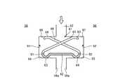
図1は、本発明の実施例1に係る燃焼器用シールとしてのシール部材を表す概略斜視図、図2は、実施例1の燃焼器のシール構造を表す概略図である。 FIG. 1 is a schematic perspective view illustrating a seal member as a combustor seal according to a first embodiment of the present invention, and FIG. 2 is a schematic diagram illustrating a seal structure of the combustor according to the first embodiment.
シール部材61は、図1に示すように、シール部材本体62と、第1突起部63及び第2突起部64と、第1ばね部材65及び第2ばね部材66とを有している。この第1ばね部材65と第2ばね部材66は、シール部材本体61の長手方向に交互に設けられている。 As shown in FIG. 1, the
シール部材本体62は、所定長さL及び所定幅Wを有する長尺形状の平板部材71を有し、基端部に細い幅の連結部72を介して取付部73が一体で形成され、この取付部73に取付孔74が形成されている。 The seal member
このシール部材本体62は、幅方向における各端部に第1突起部63及び第2突起部64が形成されている。第1突起部63は、シール部材本体62における幅方向の一端部に下方に湾曲状に突出した形状をなし、シール部材本体62(平板部材71)の長手方向に連続して形成されている。第2突起部64は、シール部材本体62における幅方向の他端部に下方に湾曲状に突出した形状をなし、シール部材本体62(平板部材71)の長手方向に連続して形成されている。 The
また、このシール部材本体62は、幅方向の一端部にて、第1突起部63から第1湾曲部81を介して第1ばね部材65が連続して一体に設けられると共に、幅方向の他端部にて、第2突起部64から第2湾曲部82を介して第2ばね部材66が連続して一体に設けられている。この第1湾曲部81及び第2湾曲部82は、シール部材本体62(平板部材71)の長手方向に連続して形成されている。 In addition, the seal member
この場合、第1湾曲部81は、シール部材本体62における幅方向の一端部の第1突起部63からほぼ同一の曲率半径をもって形成され、第1ばね部材65は、基端部がこの第1湾曲部81に接続され、先端部がシール部材本体62における幅方向の他端部側へ延出している。第2湾曲部82は、シール部材本体63における幅方向の他端部の第2突起部64からほぼ同一の曲率半径をもって形成され、第2ばね部材66は、基端部がこの第2湾曲部82に接続され、先端部がシール部材本体61における幅方向の一端部側へ延出している。 In this case, the first
そして、第1ばね部材65は、先端部側がシール部材本体62に対して徐々に離間するように所定角度をもって延出しており、先端部にシール部材本体62とほぼ平行となる第1押圧部83が設けられている。第2ばね部材66は、先端部側がシール部材本体62に対して徐々に離間するように所定角度をもって延出しており、先端部にシール部材本体62とほぼ平行となる第2押圧部84が設けられている。この場合、第1ばね部材65と第2ばね部材66は、交差するように配置され、第1押圧部83と第2突起部64とが上下に対向して配置され、第2押圧部84と第1突起部63とが上下に対向して配置されている。 The
実施例1の燃焼器のシール構造は、燃焼器尾筒43のフランジ部56とタービン入口ノズル57との接続部をシールするものであり、第1凹部91及び第2凹部92と、上述したシール部材61とにより構成されている。 The seal structure of the combustor of the first embodiment seals the connection portion between the
図2に示すように、隣接するフランジ部56は、その間に圧縮空気供給空間部54に連通する隙間93が設けられており、対向面56aにそれぞれ設けられる第1凹部91及び第2凹部92が形成されている。この第1凹部91及び第2凹部92は、燃焼ガス通路58側(図2にて、下側)に第1シール面94及び第2シール面95が形成され、圧縮空気供給空間部54側(図2にて、上側)に第1押え面96及び第2押え面97が形成されている。 As shown in FIG. 2, the
シール部材61(シール部材本体62)は、この第1凹部91及び第2凹部92に跨って配置されている。第1突起部63は、第1凹部91の第1シール面94に接触し、第2突起部64は、第2凹部92の第2シール面95に接触している。そして、第1ばね部材65は、第1押圧部83が第2凹部92の第2押え面97に当接することで、第1突起部63が第1ばね部材65の付勢力により第1シール面94に押圧される。一方、第2ばね部材66は、第2押圧部84が第1凹部91の第1押え面96に当接することで、第2突起部64が第2ばね部材66の付勢力により第2シール面95に押圧される。 The seal member 61 (the seal member main body 62) is disposed across the
第1突起部63が第1シール面94に押圧され、第2突起部64が第2シール面95に押圧されることで、第1突起部63と第1シール面94、第2突起部64と第2シール面95との接触部がシール面となる。そのため、圧縮空気供給空間部54から隙間93を通って燃焼ガス通路58に漏洩する圧縮空気をこのシール面で止めることができる。 The
このように実施例1の燃焼器のシール構造にあっては、隣接する燃焼器尾筒43のフランジ部56における対向面に設けられる第1凹部91及び第2凹部92と、第1凹部91及び第2凹部92に跨って配置されるシール部材本体62と、シール部材本体62の幅方向における各端部に設けられて第1凹部91の第1シール面94と第2凹部92の第2シール面95に接触可能な第1突起部63及び第2突起部64と、基端部がシール部材本体62における幅方向の一端部に接続されて先端部が他端部側へ延出して第2押え面97に接触可能な第1ばね部材65と、基端部がシール部材本体62における幅方向の他端部に接続されて先端部が一端部側へ延出して第1押え面96に接触可能な第2ばね部材66を設けている。 As described above, in the combustor seal structure according to the first embodiment, the first
従って、シール部材本体62が第1凹部91と第2凹部92に跨って配置され、第1ばね部材65の付勢力により第1突起部63が第1凹部91の第1シール面94に押圧され、第2ばね部材66の付勢力により第2突起部64が第2シール面95に押圧され、各突起部63,64と各シール面94,95との接触位置でシールすることで、圧縮空気と燃焼ガスとの混合を防止することができる。このシール部材61は、シール部材本体62の両側に突起部63,64とばね部材65,66が設けられたものであることから、構造を簡素化して低コスト化を可能とすることができると共に、長手方向に安定した押付力を確保することでシール性能を向上することができる。 Accordingly, the seal member
実施例1の燃焼器のシール構造では、第1シール面94及び第2シール面95を燃焼ガス通路58側に配置している。従って、圧縮空気は燃焼ガスよりも高圧であることから、各シール面94,95を燃焼ガス通路58側に配置することで、圧縮空気により突起部63,64がシール面94,95に押し付けられて離間することはなく、安定したシール性能を確保することができると共に、ばね部材65,66の付勢力を小さく抑えることで製造コストを低減することができる。 In the seal structure of the combustor of the first embodiment, the
実施例1の燃焼器のシール構造では、第1ばね部材65と第2ばね部材66をシール部材本体62の長手方向に交互に設けている。従って、各突起部63,64は、長手方向にばらつきがなく安定した押付力を確保することで、自励振動の発生を抑制することができ、その結果、シール性能を確保することができる。 In the seal structure of the combustor of the first embodiment, the
実施例1の燃焼器のシール構造では、第1突起部63から第1湾曲部81を介して第1ばね部材65が設けられ、第2突起部64から第2湾曲部82を介して第2ばね部材66が設けられている。従って、突起部63,64から湾曲部81,82を介してばね部材65,66を設けることで、シール部材61を曲げ加工により製造することが可能となり、構造を簡素化して低コスト化を可能とすることができる。 In the seal structure of the combustor according to the first embodiment, the
実施例1の燃焼器のシール構造では、シール部材本体62における幅方向の一端部から第1突起部63、第1湾曲部81、第1ばね部材65を連続して一体に設けると共に、シール部材本体62における幅方向の他端部から第2突起部64、第2湾曲部82、第2ばね部材66を連続して一体に設けている。従って、シール部材本体62、突起部63,64、湾曲部81,82、ばね部材65,66などの各構成部材を溶接などにより接合する必要がなく、製造精度を向上することができる。 In the seal structure of the combustor according to the first embodiment, the
実施例1の燃焼器のシール構造では、第1ばね部材65の先端部に第2押え面97に接触する第1押圧部83を設け、第2ばね部材66の先端部に第1押え面96に接触する第2押圧部84を設け、第1押圧部83と第2突起部64が対向して配置され、第2押圧部84と第1突起部63が対向して配置されている。従って、押圧部83,84と突起部63,64を対向して配置することで、第1押圧部83と第2突起部64を接近させると共に、第2押圧部84と第1突起部63を接近させることで、シール部材61を容易につぶして凹部91,92に挿入することができ、組付性を向上することができる。 In the seal structure of the combustor according to the first embodiment, the first pressing
また、実施例1のシール部材(燃焼器用シール)61にあっては、長尺形状をなすシール部材本体62と、シール部材本体62における幅方向の各端部に設けられて異なるシール面94,95に接触可能な第1突起部63及び第2突起部64と、基端部がシール部材本体62における幅方向の一端部に接続されて先端部が他端部側へ延出する第1ばね部材65と、基端部がシール部材本体62における幅方向の他端部に接続されて先端部が一端部側へ延出する第2ばね部材66を設けている。 Further, in the seal member (combustor seal) 61 of the first embodiment, the seal member
従って、シール部材本体62の両側に突起部63,64とばね部材65,66が設けられて構成されることで、構造を簡素化して低コスト化を可能とすることができると共に、長手方向に安定した押付力を確保することでシール性能を向上することができる。 Therefore, by providing the
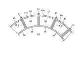
図7は、本発明の実施例2に係る燃焼器のシール構造を表す概略図である。なお、上述した実施例と同様の機能を有する部材には、同一の符号を付して詳細な説明は省略する。 FIG. 7 is a schematic diagram illustrating a combustor seal structure according to Embodiment 2 of the present invention. In addition, the same code | symbol is attached | subjected to the member which has the function similar to the Example mentioned above, and detailed description is abbreviate | omitted.
実施例2において、図7に示すように、シール部材101は、シール部材本体102と、第1突起部103及び第2突起部104と、第1ばね部材105及び第2ばね部材106とを有している。この第1ばね部材105と第2ばね部材106は、シール部材本体101の長手方向に交互に設けられている。 In Example 2, as shown in FIG. 7, the
シール部材本体102は、所定長さ及び所定幅を有する長尺形状をなしている。このシール部材本体102は、幅方向における各端部に第1突起部103及び第2突起部104が形成されており、シール部材本体102の長手方向に連続して形成されている。 The seal member
また、シール部材本体102は、幅方向の一端部にて、第1突起部103より外側に第1ばね部材105が接合されると共に、幅方向の他端部にて、第2突起部104より外側に第2ばね部材106が接合されている。 The seal member
この場合、第1ばね部材105は、基端部がシール部材本体102の一端部に溶接B1により連結され、先端部がシール部材本体102における幅方向の他端部側へ延出している。第2ばね部材106は、基端部がシール部材本体102の他端部に溶接B2により連結され、先端部がシール部材本体102における幅方向の一端部側へ延出している。 In this case, the
そして、第1ばね部材105は、先端部側がシール部材本体102に対して徐々に離間するように所定角度をもって延出しており、先端部にシール部材本体102とほぼ平行となる第1押圧部107が設けられている。第2ばね部材106は、先端部側がシール部材本体102に対して徐々に離間するように所定角度をもって延出しており、先端部にシール部材本体102とほぼ平行となる第2押圧部108が設けられている。 The
この実施例2のシール部材101は、隣接するフランジ部56に形成された第1凹部91及び第2凹部92に跨って配置されている。第1突起部103は、第1凹部91の第1シール面94に接触し、第2突起部104は、第2凹部92の第2シール面95に接触している。そして、第1ばね部材105は、第1押圧部107が第2凹部92の第2押え面97に当接することで、第1突起部103が第1ばね部材105の付勢力により第1シール面94に押圧される。一方、第2ばね部材106は、第2押圧部108が第1凹部91の第1押え面96に当接することで、第2突起部104が第2ばね部材106の付勢力により第2シール面95に押圧される。 The
第1突起部103が第1シール面94に押圧され、第2突起部104が第2シール面95に押圧されることで、第1突起部103と第1シール面94、第2突起部104と第2シール面95との接触部がシール面となる。そのため、圧縮空気供給空間部54から隙間93を通って燃焼ガス通路58に漏洩する圧縮空気をこのシール面で止めることができる。 The
このように実施例2のシール部材(燃焼器用シール)101及び燃焼器のシール構造にあっては、シール部材本体102における幅方向の各端部に異なるシール面94,95に接触可能な第1突起部103及び第2突起部104を設け、基端部がシール部材本体102における幅方向の一端部に接続されて先端部が他端部側へ延出する第1ばね部材105と、基端部がシール部材本体102における幅方向の他端部に接続されて先端部が一端部側へ延出する第2ばね部材106を設け、突起部103,104にばね部材105,106を溶接により接合している。 As described above, in the seal member (combustor seal) 101 and the seal structure of the combustor of the second embodiment, the first
従って、シール部材本体102の両側に突起部103,104とばね部材105,106が設けられて構成されることで、構造を簡素化して低コスト化を可能とすることができると共に、長手方向に安定した押付力を確保することでシール性能を向上することができる。また、突起部103,104とばね部材105,106を別部材で製作することで、構成部材の歩留まりを良くして材料コストを低減することができる。 Therefore, the
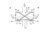
図8は、本発明の実施例3に係る燃焼器のシール構造を表す概略図である。なお、上述した実施例と同様の機能を有する部材には、同一の符号を付して詳細な説明は省略する。 FIG. 8 is a schematic diagram illustrating a seal structure of a combustor according to Embodiment 3 of the present invention. In addition, the same code | symbol is attached | subjected to the member which has the function similar to the Example mentioned above, and detailed description is abbreviate | omitted.
実施例3において、図8に示すように、シール部材111は、シール部材本体112と、第1突起部113及び第2突起部114と、第1ばね部材115及び第2ばね部材116とを有している。この第1ばね部材115と第2ばね部材116は、シール部材本体112の長手方向に交互に設けられている。 In Example 3, as illustrated in FIG. 8, the
シール部材本体112は、所定長さ及び所定幅を有する長尺形状をなしている。このシール部材本体112は、幅方向における各端部に第1突起部113及び第2突起部114が形成されており、シール部材本体112の長手方向に連続して形成されている。 The seal member
また、シール部材本体112は、幅方向の一端部にて、第1突起部113に第1ばね部材115が接合されると共に、幅方向の他端部にて、第2突起部114に第2ばね部材116が接合されている。 The seal member
この場合、第1ばね部材115は、基端部の湾曲部117が第1突起部113上に重なり、溶接B1により連結され、先端部がシール部材本体112における幅方向の他端部側へ延出している。第2ばね部材116は、基端部の湾曲部118が第2突起部114上に重なり、溶接B2により連結され、先端部がシール部材本体112における幅方向の一端部側へ延出している。 In this case, the first spring member 115 has a base end curved
そして、第1ばね部材115は、先端部側がシール部材本体112に対して徐々に離間するように所定角度をもって延出しており、先端部にシール部材本体112とほぼ平行となる第1押圧部119が設けられている。第2ばね部材116は、先端部側がシール部材本体112に対して徐々に離間するように所定角度をもって延出しており、先端部にシール部材本体112とほぼ平行となる第2押圧部120が設けられている。 The first spring member 115 extends at a predetermined angle so that the tip end side is gradually separated from the seal member
この実施例3のシール部材111は、隣接するフランジ部56に形成された第1凹部91及び第2凹部92に跨って配置されている。第1突起部113は、第1凹部91の第1シール面94に接触し、第2突起部114は、第2凹部92の第2シール面95に接触している。そして、第1ばね部材115は、第1押圧部119が第2凹部92の第2押え面97に当接することで、第1突起部113が第1ばね部材115の付勢力により第1シール面94に押圧される。一方、第2ばね部材116は、第2押圧部120が第1凹部91の第1押え面96に当接することで、第2突起部114が第2ばね部材116の付勢力により第2シール面95に押圧される。 The
第1突起部113が第1シール面94に押圧され、第2突起部114が第2シール面95に押圧されることで、第1突起部113と第1シール面94、第2突起部114と第2シール面95との接触部がシール面となる。そのため、圧縮空気供給空間部54から隙間93を通って燃焼ガス通路58に漏洩する圧縮空気をこのシール面で止めることができる。 When the
このように実施例3のシール部材(燃焼器用シール)111及び燃焼器のシール構造にあっては、シール部材本体112における幅方向の各端部に異なるシール面94,95に接触可能な第1突起部113及び第2突起部114を設け、基端部がシール部材本体112における幅方向の一端部に接続されて先端部が他端部側へ延出する第1ばね部材115と、基端部がシール部材本体112における幅方向の他端部に接続されて先端部が一端部側へ延出する第2ばね部材116を設け、突起部113,114にばね部材115,116を溶接により接合している。 As described above, in the seal member (combustor seal) 111 and the combustor seal structure according to the third embodiment, the
従って、シール部材本体112の両側に突起部113,114とばね部材115,116が設けられて構成されることで、構造を簡素化して低コスト化を可能とすることができると共に、長手方向に安定した押付力を確保することでシール性能を向上することができる。また、突起部113,114とばね部材115,116を別部材で製作することで、構成部材の歩留まりを良くして材料コストを低減することができる。 Therefore, the
なお、上述した実施例では、シール部材61,101,111にて、第1ばね部材65,105,115と第2ばね部材66,106,116をシール部材本体62,102,112の長手方向に1個ずつ交互に設けたが、複数個ずつ交互に設けてもよい。 In the embodiment described above, the
11 圧縮機
12 燃焼器
13 タービン
41 燃焼器外筒
42 燃焼器内筒
43 燃焼器尾筒
54 圧縮空気供給空間部
55 空気通路
57 タービン入口ノズル
58 燃焼ガス通路
61,101,111 シール部材(燃焼器用シール)
62,102,112 シール部材本体
63,103,113 第1突起部
64,104,114 第2突起部
65,105,115 第1ばね部材
66,106,116 第2ばね部材
81 第1湾曲部
82 第2湾曲部
83,107,119 第1押圧部
84,108,120 第2押圧部
91 第1凹部
92 第2凹部
93 隙間
94 第1シール面
95 第2シール面
96 第1押え面
97 第2押え面DESCRIPTION OF
62, 102, 112
Claims (8)
Translated fromJapanese隣接する前記尾筒出口端のフランジ部における対向面にそれぞれ設けられる第1凹部及び第2凹部と、
前記第1凹部及び前記第2凹部に跨って配置されるシール部材本体と、
前記シール部材本体の幅方向における各端部に設けられて前記第1凹部の第1シール面と前記第2凹部の第2シール面に接触可能な第1突起部及び第2突起部と、
基端部が前記シール部材本体における幅方向の一端部に接続されて先端部が他端部側へ延出して前記第2シール面に対向する前記第2凹部の第2押え面に接触可能な第1ばね部材と、
基端部が前記シール部材本体における幅方向の他端部に接続されて先端部が一端部側へ延出して前記第1シール面に対向する前記第1凹部の第1押え面に接触可能な第2ばね部材と、
を有することを特徴とする燃焼器のシール構造。In a seal structure of a combustor that seals a connection portion between a transition piece outlet end and a turbine inlet nozzle in a plurality of combustors arranged along a circumferential direction,
A first concave portion and a second concave portion respectively provided on opposing surfaces of the flange portion of the adjacent transition piece outlet end;
A seal member body disposed across the first recess and the second recess;
A first protrusion and a second protrusion provided at each end in the width direction of the seal member main body and capable of contacting the first seal surface of the first recess and the second seal surface of the second recess;
The base end portion is connected to one end portion in the width direction of the seal member main body, and the tip end portion extends to the other end portion side so as to be able to contact the second pressing surface of the second recess facing the second seal surface. A first spring member;
A base end portion is connected to the other end portion in the width direction of the seal member main body, and a tip end portion extends toward the one end portion side and can contact the first pressing surface of the first recess facing the first seal surface. A second spring member;
A combustor seal structure characterized by comprising:
前記シール部材本体における幅方向の各端部に設けられて異なるシール面に接触可能な第1突起部及び第2突起部と、
基端部が前記シール部材本体における幅方向の一端部に接続されて先端部が他端部側へ延出する第1ばね部材と、
基端部が前記シール部材本体における幅方向の他端部に接続されて先端部が一端部側へ延出する第2ばね部材と、
を有することを特徴とする燃焼器用シール。A seal member body having a long shape;
A first protrusion and a second protrusion provided at each end in the width direction of the seal member main body and capable of contacting different seal surfaces;
A first spring member having a proximal end connected to one end in the width direction of the seal member body and a distal end extending to the other end;
A second spring member having a proximal end connected to the other end in the width direction of the seal member body and a distal end extending to the one end;
A combustor seal characterized by comprising:
Priority Applications (2)
| Application Number | Priority Date | Filing Date | Title |
|---|---|---|---|
| JP2013025833AJP6021675B2 (en) | 2013-02-13 | 2013-02-13 | Combustor seal structure and seal for combustor |
| US14/177,266US9500132B2 (en) | 2013-02-13 | 2014-02-11 | Combustor seal structure and a combustor seal |
Applications Claiming Priority (1)
| Application Number | Priority Date | Filing Date | Title |
|---|---|---|---|
| JP2013025833AJP6021675B2 (en) | 2013-02-13 | 2013-02-13 | Combustor seal structure and seal for combustor |
Publications (2)
| Publication Number | Publication Date |
|---|---|
| JP2014152762A JP2014152762A (en) | 2014-08-25 |
| JP6021675B2true JP6021675B2 (en) | 2016-11-09 |
Family
ID=51296961
Family Applications (1)
| Application Number | Title | Priority Date | Filing Date |
|---|---|---|---|
| JP2013025833AExpired - Fee RelatedJP6021675B2 (en) | 2013-02-13 | 2013-02-13 | Combustor seal structure and seal for combustor |
Country Status (2)
| Country | Link |
|---|---|
| US (1) | US9500132B2 (en) |
| JP (1) | JP6021675B2 (en) |
Families Citing this family (9)
| Publication number | Priority date | Publication date | Assignee | Title |
|---|---|---|---|---|
| WO2015013503A1 (en)* | 2013-07-24 | 2015-01-29 | United Technologies Corporation | Trough seal for gas turbine engine |
| US10344609B2 (en)* | 2014-10-24 | 2019-07-09 | United Technologies Corporation | Bifurcated sliding seal |
| US10196912B2 (en) | 2014-10-24 | 2019-02-05 | United Technologies Corporation | Bifurcated sliding seal |
| US9790809B2 (en) | 2015-03-24 | 2017-10-17 | United Technologies Corporation | Damper for stator assembly |
| US9845698B2 (en)* | 2015-06-24 | 2017-12-19 | Siemens Energy, Inc. | Belly band seal with anti-rotation structure |
| FR3065986B1 (en)* | 2017-05-02 | 2021-07-09 | Safran Aircraft Engines | ASSEMBLY FOR GAS TURBINE, ASSOCIATED GAS TURBINE |
| US11506069B2 (en)* | 2021-03-03 | 2022-11-22 | Raytheon Technologies Corporation | Vane arc segment with spring seal |
| CN113550830B (en)* | 2021-08-26 | 2022-11-25 | 中国联合重型燃气轮机技术有限公司 | Sealing device and gas turbine with same |
| FR3158532A1 (en)* | 2024-01-19 | 2025-07-25 | Safran Aircraft Engines | Turbomachine sealing assembly and associated assembly method |
Family Cites Families (25)
| Publication number | Priority date | Publication date | Assignee | Title |
|---|---|---|---|---|
| JPS5970814A (en)* | 1982-10-13 | 1984-04-21 | ソ−ラ−・タ−ビンズ・インコ−ポレ−テツド | Gas turbine engine |
| US4897021A (en)* | 1988-06-02 | 1990-01-30 | United Technologies Corporation | Stator vane asssembly for an axial flow rotary machine |
| US5125796A (en)* | 1991-05-14 | 1992-06-30 | General Electric Company | Transition piece seal spring for a gas turbine |
| JPH102203A (en)* | 1996-06-17 | 1998-01-06 | Mitsubishi Heavy Ind Ltd | Gas turbine cooling stationary blade |
| US6547257B2 (en) | 2001-05-04 | 2003-04-15 | General Electric Company | Combination transition piece floating cloth seal and stage 1 turbine nozzle flexible sealing element |
| US6883807B2 (en)* | 2002-09-13 | 2005-04-26 | Seimens Westinghouse Power Corporation | Multidirectional turbine shim seal |
| US6733234B2 (en)* | 2002-09-13 | 2004-05-11 | Siemens Westinghouse Power Corporation | Biased wear resistant turbine seal assembly |
| JP4577813B2 (en)* | 2003-08-20 | 2010-11-10 | イーグル・エンジニアリング・エアロスペース株式会社 | Sealing device |
| JP4322600B2 (en)* | 2003-09-02 | 2009-09-02 | イーグル・エンジニアリング・エアロスペース株式会社 | Sealing device |
| US8714565B1 (en)* | 2005-01-27 | 2014-05-06 | Parker-Hannifim Corporation | Seal |
| CN101694181B (en) | 2005-08-23 | 2012-09-05 | 三菱重工业株式会社 | Seal structure of gas turbine combustor |
| US20070212214A1 (en)* | 2006-03-09 | 2007-09-13 | United Technologies Corporation | Segmented component seal |
| US20090085305A1 (en)* | 2007-09-28 | 2009-04-02 | General Electric Company | High temperature seal |
| DE102007062681A1 (en)* | 2007-12-24 | 2009-06-25 | Man Turbo Ag | Sealing segment and sealing segment arrangement |
| US7594401B1 (en) | 2008-04-10 | 2009-09-29 | General Electric Company | Combustor seal having multiple cooling fluid pathways |
| US8511972B2 (en)* | 2009-12-16 | 2013-08-20 | Siemens Energy, Inc. | Seal member for use in a seal system between a transition duct exit section and a turbine inlet in a gas turbine engine |
| US8434999B2 (en) | 2010-03-25 | 2013-05-07 | General Electric Company | Bimetallic spline seal |
| US8398090B2 (en)* | 2010-06-09 | 2013-03-19 | General Electric Company | Spring loaded seal assembly for turbines |
| US9945484B2 (en)* | 2011-05-20 | 2018-04-17 | Siemens Energy, Inc. | Turbine seals |
| US8562000B2 (en)* | 2011-05-20 | 2013-10-22 | Siemens Energy, Inc. | Turbine combustion system transition piece side seals |
| US20130028713A1 (en)* | 2011-07-25 | 2013-01-31 | General Electric Company | Seal for turbomachine segments |
| JP6029274B2 (en)* | 2011-11-10 | 2016-11-24 | 三菱日立パワーシステムズ株式会社 | Seal assembly and gas turbine provided with the same |
| US8920112B2 (en)* | 2012-01-05 | 2014-12-30 | United Technologies Corporation | Stator vane spring damper |
| US8899914B2 (en)* | 2012-01-05 | 2014-12-02 | United Technologies Corporation | Stator vane integrated attachment liner and spring damper |
| US20140062032A1 (en)* | 2012-07-27 | 2014-03-06 | General Electric Company | Spring-loaded seal assembly |
- 2013
- 2013-02-13JPJP2013025833Apatent/JP6021675B2/ennot_activeExpired - Fee Related
- 2014
- 2014-02-11USUS14/177,266patent/US9500132B2/ennot_activeExpired - Fee Related
Also Published As
| Publication number | Publication date |
|---|---|
| JP2014152762A (en) | 2014-08-25 |
| US20140225334A1 (en) | 2014-08-14 |
| US9500132B2 (en) | 2016-11-22 |
Similar Documents
| Publication | Publication Date | Title |
|---|---|---|
| JP6021675B2 (en) | Combustor seal structure and seal for combustor | |
| US8678754B2 (en) | Assembly for preventing fluid flow | |
| JP6134580B2 (en) | Turbomachine combustor nozzle including monolithic nozzle component and method of forming the same | |
| JP4690905B2 (en) | SEALING DEVICE AND GAS TURBINE HAVING THE SAME | |
| TWI627347B (en) | Assembly structure and method of seal member, seal member, and gas turbine | |
| JP2018059502A (en) | Corner flow reduction seals | |
| JP2008261605A (en) | Gas turbine combustor | |
| JP2012082818A (en) | Shim for sealing transition pieces | |
| WO2009107418A1 (en) | Turbine disc and gas turbine | |
| JP2008025910A (en) | Gas turbine combustor | |
| CN107869361B (en) | Improved pressure loaded seal | |
| US8888445B2 (en) | Turbomachine seal assembly | |
| JP2017180351A (en) | Combustor and gas turbine | |
| KR101986021B1 (en) | Sealing assembly and gas turbine comprising the same | |
| CN107869734A (en) | Advanced seals with reduced corner leakage | |
| US20160281593A1 (en) | Variable nozzle unit and variable geometry system turbocharger | |
| US8632075B2 (en) | Seal assembly and method for flowing hot gas in a turbine | |
| JP2017101670A (en) | Turbomachine blade cover plate with radial cooling grooves | |
| JP2012102869A (en) | Transition piece sealing assembly with seal overlay | |
| CN108350809B (en) | Combustion canisters, gas turbine combustors, and gas turbines | |
| US20120269622A1 (en) | Turbine vane and gas turbine | |
| JP7130545B2 (en) | Gas turbine combustor, gas turbine, and method for manufacturing gas turbine combustor | |
| JP6917278B2 (en) | Ring seal of gas turbine and gas turbine | |
| KR20190103762A (en) | Sealing structure of turbine, turbine and gas turbine comprising it | |
| US11085642B2 (en) | Combustor with radially varying leading end portion of basket and gas turbine |
Legal Events
| Date | Code | Title | Description |
|---|---|---|---|
| A621 | Written request for application examination | Free format text:JAPANESE INTERMEDIATE CODE: A621 Effective date:20151104 | |
| A977 | Report on retrieval | Free format text:JAPANESE INTERMEDIATE CODE: A971007 Effective date:20160831 | |
| TRDD | Decision of grant or rejection written | ||
| A01 | Written decision to grant a patent or to grant a registration (utility model) | Free format text:JAPANESE INTERMEDIATE CODE: A01 Effective date:20160906 | |
| A61 | First payment of annual fees (during grant procedure) | Free format text:JAPANESE INTERMEDIATE CODE: A61 Effective date:20161004 | |
| R151 | Written notification of patent or utility model registration | Ref document number:6021675 Country of ref document:JP Free format text:JAPANESE INTERMEDIATE CODE: R151 | |
| LAPS | Cancellation because of no payment of annual fees |