JP6020907B2 - Display device - Google Patents
Display deviceDownload PDFInfo
- Publication number
- JP6020907B2 JP6020907B2JP2012257201AJP2012257201AJP6020907B2JP 6020907 B2JP6020907 B2JP 6020907B2JP 2012257201 AJP2012257201 AJP 2012257201AJP 2012257201 AJP2012257201 AJP 2012257201AJP 6020907 B2JP6020907 B2JP 6020907B2
- Authority
- JP
- Japan
- Prior art keywords
- display
- light
- mirror
- display element
- emitting diode
- Prior art date
- Legal status (The legal status is an assumption and is not a legal conclusion. Google has not performed a legal analysis and makes no representation as to the accuracy of the status listed.)
- Expired - Fee Related
Links
- 238000005286illuminationMethods0.000claimsdescription4
- 239000011347resinSubstances0.000description5
- 229920005989resinPolymers0.000description5
- 230000005540biological transmissionEffects0.000description4
- 239000004743PolypropyleneSubstances0.000description2
- 229910052782aluminiumInorganic materials0.000description2
- XAGFODPZIPBFFR-UHFFFAOYSA-NaluminiumChemical compound[Al]XAGFODPZIPBFFR-UHFFFAOYSA-N0.000description2
- 229910052751metalInorganic materials0.000description2
- 239000002184metalSubstances0.000description2
- 239000004417polycarbonateSubstances0.000description2
- 229920000515polycarbonatePolymers0.000description2
- -1polypropylenePolymers0.000description2
- 229920001155polypropylenePolymers0.000description2
- 239000002390adhesive tapeSubstances0.000description1
- 238000000151depositionMethods0.000description1
- 238000010586diagramMethods0.000description1
- 239000004973liquid crystal related substanceSubstances0.000description1
- 238000000034methodMethods0.000description1
- 230000005855radiationEffects0.000description1
- 230000009466transformationEffects0.000description1
Images


Landscapes
- Projection Apparatus (AREA)
- Instrument Panels (AREA)
- Devices For Indicating Variable Information By Combining Individual Elements (AREA)
Description
Translated fromJapanese本発明は、DMD(Digital Micromirror Device)等の表示素子を備えた表示装置に関するものである。 The present invention relates to a display device including a display element such as a DMD (Digital Micromirror Device).
従来より、スクリーンに表示光を投影する投射型表示装置が種々提案されており、例えば特許文献1に開示されている。斯かる投射型表示装置は、画像投射装置,外装筐体,スクリーン,反射ミラーを備えており、スクリーン上に投影される画像の位置を調整できるようになっている。 Conventionally, various projection-type display devices that project display light onto a screen have been proposed. Such a projection display device includes an image projection device, an exterior housing, a screen, and a reflection mirror, and can adjust the position of an image projected on the screen.
しかしながら、前記投射型表示装置は、軸止部を中心として、反射ミラーを上下左右に回転可能に軸止する構造であるため、スクリーンに投影される画像の位置を調整し難いという問題を有していた。
本発明は、この問題に鑑みなされたものであり、表示素子の位置調整が容易にできる光源装置を提供するものである。However, the projection type display device has a structure in which the reflection mirror is pivotally fixed up and down and right and left around the axis stop portion, so that it is difficult to adjust the position of the image projected on the screen. It was.
The present invention has been made in view of this problem, and provides a light source device capable of easily adjusting the position of a display element.
本発明は、照明光を発する光源11と、前記照明光から表示光Lを生成する表示素子141と、前記表示素子141が搭載される回路基板142と、前記表示素子141を保持する調整部材143と、前記調整部材143を位置調整可能に固定する固定手段148と、を備え、前記調整部材143は突起143aを有すると共に、前記回路基板142に形成された貫通孔142aに前記突起143aが挿入されて、前記表示素子141が搭載された前記回路基板142が前記調整部材143に位置決めされているものである。The present invention includes a
また、本発明は、前記表示光Lを反射させる反射部材21を備えたものである。 In addition, the present invention includes a reflecting
また、本発明は、前記固定手段148はボルトであるものである。 In the present invention, the fixing means 148 is a bolt.
また、本発明は、前記調整部材143は、前記ボルト148の軸部148bが貫通する貫通孔143cを有するものである。 In the present invention, the adjusting
表示素子を調整部材で保持し、この調整部材を位置調整可能に固定することにより、表示素子の位置調整が容易にできる。 The position of the display element can be easily adjusted by holding the display element with the adjustment member and fixing the adjustment member so that the position of the display element can be adjusted.
以下、添付の図面に基づいて、本発明をヘッドアップディスプレイ装置に適用した一実施形態を説明する。 Hereinafter, an embodiment in which the present invention is applied to a head-up display device will be described with reference to the accompanying drawings.
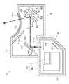
ヘッドアップディスプレイ装置は、車両のダッシュボード1に設けられた表示装置2が投射する表示光Lをフロントガラス3によって車両運転者4側に反射させ、虚像Vを表示するものである。車両運転者4は、虚像Vを風景と重畳させて視認することができる。表示装置2は、第1ユニットA及び第2ユニットBを備えている。 The head-up display device displays the virtual image V by reflecting the display light L projected by the
第1ユニットAは、プロジェクタ10,平面鏡21,透過型スクリーン26,ヒートシンク31,ハウジング41等から構成されている。第2ユニットBは、反射器50,60,ハウジング71等から構成されている。 The first unit A includes a
プロジェクタ10は、フィールドシーケンシャル方式によって、透過型スクリーン26に画像を表示させるものである。プロジェクタ10は、光源部11,ミラー部12,プリズム13,表示器14,投射レンズ部材15を有しており、ヒートシンク31に固定されている。 The
プロジェクタ10の光源部11は、青色発光ダイオード11a,赤色発光ダイオード11b,緑色発光ダイオード11c,レンズ部材11d,11e,11f,反射ミラー11g,ダイクロイックミラー11h,11i,回路基板11kを有するものである。レンズ部材11d,11e,11f,反射ミラー11g,ダイクロイックミラー11h,11iは、フレーム部材11mの保持部11vで保持されている。 The
青色発光ダイオード11a,赤色発光ダイオード11b,緑色発光ダイオード11cは、トップビュー型LEDからなるものであり、夫々、青色光B,赤色光R,緑色光Gを発するものである。青色発光ダイオード11a,赤色発光ダイオード11b,緑色発光ダイオード11cは回路基板11kに搭載されている。青色発光ダイオード11a,赤色発光ダイオード11b,緑色発光ダイオード11cが搭載された回路基板11kは、図示しないボルトによってヒートシンク31に固定されている。回路基板11kはヒートシンク31に当接しており、青色発光ダイオード11a,赤色発光ダイオード11b,緑色発光ダイオード11cが発した熱は、回路基板11kを介して、ヒートシンク31によって放散される。 The blue light-
レンズ部材11d,11e,11fは、夫々、青色発光ダイオード11a,赤色発光ダイオード11b,緑色発光ダイオード11cが発した青色光B,赤色光R,緑色光Gを集光させる。反射ミラー11gは、青色発光ダイオード11aが発してレンズ部材11dで集光された青色光Bを反射させる。ダイクロイックミラー11hは、赤色発光ダイオード11bが発してレンズ部材11eで集光された赤色光Rを反射させると共に、反射ミラー11gで反射された青色光Bを透過させる。ダイクロイックミラー11iは、緑色発光ダイオード11cが発してレンズ部材11fで集光された緑色光Gを反射させると共に、反射ミラー11hで透過または反射された青色光B,赤色光Rを透過させる。 The
フレーム部材11mは、突起からなる位置決め部11pを有している。フレーム部材11の位置決め部11pをヒートシンク31の凹部に嵌め入れることにより、フレーム部材11がヒートシンク31に位置決めされる。また、フレーム部材11mには孔部11tが形成されている。フレーム部材11mの孔部11tにボルト11sが挿通され、ボルト11sがヒートシンク31に螺着されることにより、フレーム部材11mがヒートシンク31に固定される。 The
表示ユニット19は、ミラー部12,プリズム13,表示器14,投射レンズ部材15をケース体18に収容したものである。表示ユニット19は、光源部11とは直接的には接触していない。プリズム13は、ミラー部12からの光を透過させて表示器14に照射させる。表示器14によって生成された表示光Lは、プリズム13の傾斜面13aによって、投射レンズ部材15に向けて反射される。投射レンズ部材15は、表示光Lを拡大し、平面鏡21に投射する。投射レンズ部材15は、1枚のレンズ部材で構成しても良いし、複数のレンズ部材で構成しても良い。 The
平面鏡21は、支持部材23に保持されており、プロジェクタ10からの表示光Lを透過型スクリーン26に反射させる。透過型スクリーン26は支持部材24に保持されており、プロジェクタ10からの表示光Lが透過型スクリーン26に結像される。ヒートシンク31は、アルミニウム(Al)等の金属からなるものであり、複数の放熱フィン31aを有している。平面鏡21及び透過型スクリーン26は、保持部材23,24を介して、ヒートシンク31に固定されている。ハウジング41は、不透明な樹脂(例えばポリプロピレン)からなるものであり、プロジェクタ10,平面鏡21,透過型スクリーン26等を収容する。ハウジング41には、表示光Lが出射する窓部41aが形成されている。 The
反射器50は、平面鏡51及び支持部材52を有している。平面鏡51は、第1ユニットAからの表示光Lを凹面鏡61に反射させる。支持部材52は、ハウジング71に固定されており、平面鏡35を保持する。反射器60は、凹面鏡61,ミラーホルダー62,ステッピングモータ63,支持部材64を有している。凹面鏡61は、樹脂(例えばポリカーボネート)に金属(例えばアルミニウム)を蒸着させ反射面61aを形成したものである。反射面61aは凹面となっており、平面鏡51にて反射された表示光Lが拡大されて虚像Vが表示される。凹面鏡61はミラーホルダー62に両面粘着テープにより接着されている。ミラーホルダー62は樹脂(例えばABS)からなるものであり、歯車部65及び軸部66が一体に形成されている。 The
ステッピングモータ63の回動軸には歯車67が取付けられており、この歯車67は、ミラーホルダー62の歯車部65と噛合されている。凹面鏡61はミラーホルダー62と共に回動可能な状態で支持されており、ステッピングモータ63により凹面鏡61を回動させ、表示光Lの投射方向を調整することができる。車両運転者4は、押ボタンスイッチ(図示しない)を操作し表示光Lが目の位置に反射されるように(即ち、虚像Vを視認できるように)凹面鏡61の角度を調整する。 A
ハウジング71は、不透明な樹脂(例えばポリプロピレン)からなり、反射器50,60が収容される。ハウジング71には遮光壁71aが設けられており、太陽光等の外光が透過型スクリーン26に入射し虚像Vが見えにくくなる現象(ウォッシュアウト)を防止している。遮光壁71aは平板形状になっており、ハウジング71の上部から斜めに垂下するように形成されている。ハウジング71の上面には、表示光Lが出射する開口部71bが形成されており、この開口部71bには、透光性カバー72が貼着されている。透光性カバー72は、ポリカーボネート等の透明樹脂からなるものであり、湾曲形状になっている。 The
次に、図5に基づいて、表示器14について詳述する。表示器14は、反射型表示素子141と、回路基板142と、調整板143と、ベース部材145と、を有している。表示器14は、ボルト148によって、ケース体18に固定されている。 Next, the
反射型表示素子141は、DMD(Digital Micromirror Device)141aとソケット141bとからなるものであり、回路基板142に搭載されている。DMD141aは多数の微小な鏡面を平面に配列したものであり、DMD141aはソケット141bに保持されている。ソケット141bには突起141cが形成されており、この突起141cによりソケット141bが調整板143に位置決めされている。 The
回路基板142には貫通孔142aが形成されており、この貫通孔142aに調整板143の突起143aが挿入され、回路基板142が調整板143に位置決めされている。反射型表示素子141が搭載された回路基板142は、ベース部材145が調整板143に固定されることによって保持されている。ベース部材145には貫通孔145aが形成されており、この貫通孔145aに調整板143の突起143aが挿入されている。ベース部材145は、ボルト147によって、調整板143に固定されている。 A through
調整板143には貫通孔143cが形成されており、この貫通孔143cにボルト148の軸部148bが挿通されている。ボルト148は頭部148aと軸部148bとからなるものであり、軸部148bには雄ネジが形成されている。貫通孔143cの内径は、軸部148bの外径よりも大きくなっており、調整板143を固定しているボルト148を緩めることにより、反射型表示素子141が位置決めされた調整板143の位置を調整することができる。 A through
なお、本発明は、本実施形態に限定されるものではなく、種々の変形が可能である。例えば、本実施形態の表示素子は反射型表示素子141であったが、液晶表示素子等の透過型表示素子であっても良い。また、本実施形態の固定部材はボルト148であったが、ビスであっても良い。 In addition, this invention is not limited to this embodiment, A various deformation | transformation is possible. For example, the display element of this embodiment is the
11 光源部(光源)
21 平面鏡(反射部材)
141 反射型表示素子(表示素子)
143 調整板(調整部材)
143c 貫通孔
148 ボルト(固定手段)
148b 軸部
L 表示光11 Light source (light source)
21 Plane mirror (reflective member)
141 Reflective display element (display element)
143 Adjustment plate (adjustment member)
143c Through-
148b Shaft L Display light
Claims (4)
Translated fromJapanese前記調整部材は突起を有すると共に、
前記回路基板に形成された貫通孔に前記突起が挿入されて、
前記表示素子が搭載された前記回路基板が前記調整部材に位置決めされていることを特徴とする表示装置。A light source that emits illumination light, a display element that generates display light from the illumination light,a circuit board on which the display element is mounted, an adjustment member that holds the display element, and an adjustment member that can be adjusted in position. Fixing means,
The adjustment member has a protrusion,
The protrusion is inserted into a through hole formed in the circuit board,
The display device, wherein the circuit board on which the display element is mounted is positioned on the adjustment member .
The display device according to claim 3, wherein the adjustment member has a through hole through which a shaft portion of the bolt passes.
Priority Applications (1)
| Application Number | Priority Date | Filing Date | Title |
|---|---|---|---|
| JP2012257201AJP6020907B2 (en) | 2012-11-26 | 2012-11-26 | Display device |
Applications Claiming Priority (1)
| Application Number | Priority Date | Filing Date | Title |
|---|---|---|---|
| JP2012257201AJP6020907B2 (en) | 2012-11-26 | 2012-11-26 | Display device |
Publications (2)
| Publication Number | Publication Date |
|---|---|
| JP2014106270A JP2014106270A (en) | 2014-06-09 |
| JP6020907B2true JP6020907B2 (en) | 2016-11-02 |
Family
ID=51027846
Family Applications (1)
| Application Number | Title | Priority Date | Filing Date |
|---|---|---|---|
| JP2012257201AExpired - Fee RelatedJP6020907B2 (en) | 2012-11-26 | 2012-11-26 | Display device |
Country Status (1)
| Country | Link |
|---|---|
| JP (1) | JP6020907B2 (en) |
Families Citing this family (5)
| Publication number | Priority date | Publication date | Assignee | Title |
|---|---|---|---|---|
| JP6696174B2 (en)* | 2015-12-25 | 2020-05-20 | 日本精機株式会社 | Display device |
| FR3056686B1 (en)* | 2016-09-28 | 2020-05-29 | Valeo Vision | FIXING A MICRO-MIRROR MATRIX IN A LIGHT DEVICE |
| FR3056685B1 (en)* | 2016-09-28 | 2021-01-15 | Valeo Vision | MONOBLOC BRACKET FOR LUMINOUS DEVICES WITH MICRO-MIRRORS MATRIX |
| JP7013830B2 (en)* | 2017-01-26 | 2022-02-01 | 日本精機株式会社 | Head-up display device |
| JP2021089412A (en)* | 2019-11-21 | 2021-06-10 | 株式会社リコー | Light reflection device and movable body |
Family Cites Families (3)
| Publication number | Priority date | Publication date | Assignee | Title |
|---|---|---|---|---|
| JP2006133409A (en)* | 2004-11-04 | 2006-05-25 | Funai Electric Co Ltd | Projector |
| JP2007041529A (en)* | 2005-06-30 | 2007-02-15 | Konica Minolta Opto Inc | Method for manufacturing projection optical system and projection optical system |
| JP5038387B2 (en)* | 2009-12-22 | 2012-10-03 | 株式会社コシナ | Projector lens device |
- 2012
- 2012-11-26JPJP2012257201Apatent/JP6020907B2/ennot_activeExpired - Fee Related
Also Published As
| Publication number | Publication date |
|---|---|
| JP2014106270A (en) | 2014-06-09 |
Similar Documents
| Publication | Publication Date | Title |
|---|---|---|
| JP7206361B2 (en) | head-up display device | |
| JP4883283B2 (en) | Display device | |
| JP5353203B2 (en) | Head-up display device | |
| JP4831474B2 (en) | Head-up display device for vehicle | |
| JP6098868B2 (en) | Head-up display device | |
| JP6372346B2 (en) | Head-up display | |
| JP4941070B2 (en) | Vehicle display device | |
| JP6020907B2 (en) | Display device | |
| JP6094203B2 (en) | Vehicle display device | |
| JP2009288388A (en) | Display device | |
| JP2011150099A (en) | Mirror unit | |
| WO2017203916A1 (en) | Head-up display device | |
| CN105319810A (en) | Lens adjusting module and projector | |
| JP2013178308A (en) | Display device | |
| JP2008257021A (en) | Display device | |
| JP2014085657A (en) | Display device | |
| JP2017049570A (en) | Mirror unit | |
| JP2009067352A (en) | Head-up display device | |
| JP2017102230A (en) | Mirror unit | |
| JP2010132207A (en) | Head-up display device | |
| JP6696174B2 (en) | Display device | |
| JP2014174221A (en) | Light source device | |
| JP4985921B2 (en) | Display device | |
| JP6600742B2 (en) | Display device and vehicle head-up display device | |
| JP2017194615A (en) | Mirror unit |
Legal Events
| Date | Code | Title | Description |
|---|---|---|---|
| A621 | Written request for application examination | Free format text:JAPANESE INTERMEDIATE CODE: A621 Effective date:20150918 | |
| A131 | Notification of reasons for refusal | Free format text:JAPANESE INTERMEDIATE CODE: A131 Effective date:20160721 | |
| A977 | Report on retrieval | Free format text:JAPANESE INTERMEDIATE CODE: A971007 Effective date:20160720 | |
| A521 | Request for written amendment filed | Free format text:JAPANESE INTERMEDIATE CODE: A523 Effective date:20160809 | |
| TRDD | Decision of grant or rejection written | ||
| A01 | Written decision to grant a patent or to grant a registration (utility model) | Free format text:JAPANESE INTERMEDIATE CODE: A01 Effective date:20160908 | |
| A61 | First payment of annual fees (during grant procedure) | Free format text:JAPANESE INTERMEDIATE CODE: A61 Effective date:20160921 | |
| R150 | Certificate of patent or registration of utility model | Ref document number:6020907 Country of ref document:JP Free format text:JAPANESE INTERMEDIATE CODE: R150 | |
| LAPS | Cancellation because of no payment of annual fees |