JP6018779B2 - Sample collection device - Google Patents
Sample collection deviceDownload PDFInfo
- Publication number
- JP6018779B2 JP6018779B2JP2012085188AJP2012085188AJP6018779B2JP 6018779 B2JP6018779 B2JP 6018779B2JP 2012085188 AJP2012085188 AJP 2012085188AJP 2012085188 AJP2012085188 AJP 2012085188AJP 6018779 B2JP6018779 B2JP 6018779B2
- Authority
- JP
- Japan
- Prior art keywords
- chamber
- plunger
- saliva
- cylinder
- hollow
- Prior art date
- Legal status (The legal status is an assumption and is not a legal conclusion. Google has not performed a legal analysis and makes no representation as to the accuracy of the status listed.)
- Active
Links
Images


Landscapes
- Sampling And Sample Adjustment (AREA)
Description
Translated fromJapanese本発明は、液状検体を簡便に、かつ高精度で定量採取することができる検体採取器具に関する。 The present invention relates to a sample collection device capable of collecting a liquid sample simply and with high accuracy.
唾液、血液、尿、呼気等の生体サンプルに含まれる特定成分(バイオマーカー)を検出又は定量して、ヒトの疾病や健康状態を診断する技術が近年注目を浴びている。中でも唾液等の生体サンプルを用いる場合には、非侵襲で生体サンプルを採取し、診断を行えるという利点がある。バイオマーカーとしては例えば、ストレス関連物質である、唾液に含まれるコルチゾールがある。 In recent years, a technique for diagnosing a human disease or health condition by detecting or quantifying a specific component (biomarker) contained in a biological sample such as saliva, blood, urine, or exhaled breath has attracted attention. In particular, when a biological sample such as saliva is used, there is an advantage that a biological sample can be collected non-invasively and diagnosed. An example of a biomarker is cortisol contained in saliva, which is a stress-related substance.
液状の生体サンプル、例えば唾液中のバイオマーカーを定量しようとする場合には、唾液採取用のスワブを口に含み、スワブに唾液を吸収させた後、遠心分離機等を用いて唾液を分離回収し、次いで、所定量の唾液をマイクロピペットを用いて定量し、分析装置に導入するという、煩雑な操作を経ることが一般的であった。このような事情に鑑み、液状検体を分析する場合において、できるだけ簡便に、また望ましくは、できるだけ安全、衛生的に液状検体を定量採取できる器具が求められている。 When quantifying biomarkers in liquid biological samples, such as saliva, swabs for collecting saliva are included in the mouth, and after the saliva is absorbed by the swabs, saliva is separated and recovered using a centrifuge, etc. Then, it is common that a predetermined amount of saliva is quantified using a micropipette and then introduced into an analyzer, which is a complicated operation. In view of such circumstances, there is a need for an instrument capable of quantitatively collecting a liquid sample as easily as possible and desirably as safely and hygienically as possible when analyzing a liquid sample.
特開2004−219309号公報(特許文献1)には、ピストン部分の先端部を口に入れて該先端部に唾液を吸収させた後、ピストン部分をシリンジ部分に挿入し、圧搾することにより唾液を分離採取する唾液採取回収器具が開示されている。しかしながら、この器具は、唾液の定量的な採取が難しいという問題があった。 JP-A-2004-219309 (Patent Document 1) discloses that saliva is obtained by inserting the piston portion into the syringe portion and pressing the piston portion after the tip portion of the piston portion is put into the mouth and the tip portion absorbs saliva. A saliva collection / collection device for separately collecting the saliva is disclosed. However, this device has a problem that it is difficult to quantitatively collect saliva.
本発明の目的は、スワブ等の吸収体に吸収されている液状検体を簡便に、かつ高精度で定量採取することができる検体採取器具を提供することにある。 An object of the present invention is to provide a sample collection device capable of easily and quantitatively collecting a liquid sample absorbed in an absorbent body such as a swab with high accuracy.
本発明は、以下のものを含む。
[1] 第1中空部を有する第1シリンダ、及び、第1中空部に収容される、液状検体を吸収保持する吸収体を圧搾して、液状検体を取り出すための第1プランジャから構成される圧搾部と、
第2中空部を有する第2シリンダ、及び、第2中空部に挿入される第2プランジャから構成されており、前記吸収体から取り出された液状検体のうちの所定量を第1中空部から排出させるための定量部と、
第1中空部及び第2中空部と空間的に接続されており、第1中空部から排出された所定量の液状検体を収容するための収容部と、
を含む検体採取器具。The present invention includes the following.
[1] Consists of a first cylinder having a first hollow portion and a first plunger for squeezing an absorbent body that absorbs and holds the liquid sample, and is taken out of the first hollow portion to take out the liquid sample. A pressing part;
It is comprised from the 2nd cylinder which has a 2nd hollow part, and the 2nd plunger inserted in a 2nd hollow part, The predetermined amount of the liquid sample taken out from the said absorber is discharged | emitted from a 1st hollow part A quantitative unit for
A storage section that is spatially connected to the first hollow section and the second hollow section, and stores a predetermined amount of liquid specimen discharged from the first hollow section;
Sample collection equipment including
[2] 収容部は、第1中空部に対して着脱自在に接続されている[1]に記載の検体採取器具。 [2] The specimen collecting instrument according to [1], wherein the accommodating portion is detachably connected to the first hollow portion.
[3] 圧搾部の第1シリンダ又は第1プランジャに、第1中空部内の空気を排出するための空気排出口が設けられている[1]又は[2]に記載の検体採取器具。 [3] The specimen collecting instrument according to [1] or [2], wherein the first cylinder or the first plunger of the pressing unit is provided with an air discharge port for discharging the air in the first hollow part.
[4] 第1中空部は、第1プランジャが挿入される側から順に、第1チャンバ、及び、第1チャンバに連結される第2チャンバを含み、
第2チャンバの断面積は、第1チャンバの断面積より小さい[1]〜[3]のいずれかに記載の検体採取器具。[4] The first hollow portion includes, in order from the side where the first plunger is inserted, a first chamber and a second chamber connected to the first chamber,
The sample collection instrument according to any one of [1] to [3], wherein the cross-sectional area of the second chamber is smaller than the cross-sectional area of the first chamber.
[5] 第1中空部は、第2チャンバにおける第1チャンバが連結される側とは反対側に連結される第3チャンバをさらに含み、
第3チャンバの断面積は、第2チャンバの断面積より小さい[4]に記載の検体採取器具。[5] The first hollow portion further includes a third chamber connected to the opposite side of the second chamber to the side to which the first chamber is connected,
The specimen collecting instrument according to [4], wherein the cross-sectional area of the third chamber is smaller than the cross-sectional area of the second chamber.
本発明によれば、液状検体を簡便に、安全かつ衛生的に、さらには高精度で定量採取することができる検体採取器具を提供することができる。本発明の検体採取器具は、構成部品点数が少なく、低コストでの量産が可能であるため、使い捨て式の検体採取器具として好適である。 According to the present invention, it is possible to provide a sample collection device capable of quantitatively collecting a liquid sample simply, safely and hygienically, and with high accuracy. The sample collection device of the present invention is suitable as a disposable sample collection device because it has a small number of components and can be mass-produced at low cost.
<第1の実施形態>
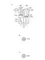
図1は、本実施形態に係る検体採取器具を示す概略図であり、図1(a)がその概略断面図、図1(b)及び図1(c)はそれぞれ、第1プランジャ101の先端部101a、第2プランジャ201の先端部201aの形状を示す上面図である。<First Embodiment>
FIG. 1 is a schematic view showing a sample collection device according to the present embodiment. FIG. 1A is a schematic cross-sectional view thereof, and FIGS. 1B and 1C are front ends of a
本実施形態に係る検体採取器具は、唾液等の液状検体を吸収保持する吸収体から、液状検体を精度良く定量しながら採取できる器具であり、2つのピストン機構(圧搾部100としてのピストン機構と定量部200としてのピストン機構)を配管(収容部300)で接続したような簡易な構造を有している。より具体的には、この検体採取器具は、液状検体を吸収保持する吸収体を圧搾して、液状検体の取り出しを行うための圧搾部100;吸収体から取り出された液状検体のうちの所定量を定量するための定量部200;及び、定量された液状検体を収容するための収容部300から構成される。 The sample collection device according to the present embodiment is a device that can collect a liquid sample while accurately quantifying it from an absorber that absorbs and holds a liquid sample such as saliva, and includes two piston mechanisms (a piston mechanism as the
圧搾部100は、第1中空部を有する第1シリンダ102、及び、第1中空部に挿入される第1プランジャ101からなる。本発明において「シリンダ」とは、筒状体を意味し、内部に空間(中空部)を有するものである。「プランジャ」とは、シリンダの中空部に挿入されるピストン棒であり、中空部に挿入した状態で往復運動自在なものである。本実施形態において第1中空部は、第1プランジャ101が挿入される側から順に、第1チャンバ151、第1チャンバ151に連結される第2チャンバ152、及び、第2チャンバ152に連結される第3チャンバ153から構成されている。本実施形態では、第2チャンバ152の断面積が第1チャンバ151の断面積より小さく、また、第3チャンバ153の断面積が第2チャンバ152の断面積より小さくなるように設計されている。 The
第1シリンダ102の第1中空部に挿入された第1プランジャ101を押すことにより、液状検体を吸収保持する吸収体が圧搾され、吸収体から液状検体が取り出される。 By pushing the
定量部200は、第2中空部251を有する第2シリンダ202、及び、第2中空部251に挿入される第2プランジャ201からなる。第2シリンダ202の第2中空部251に挿入された第2プランジャ201を引くことにより、吸収体から取り出された液状検体のうちの所定量が第1中空部から排出され、収容部300内に収容される。 The
図1(b)に示されるように、第1プランジャ101の先端部101aは切り欠き部を有しており、この切り欠き部は、第1中空部内の空気を排出するための空気排出口である。一方、第2プランジャ201の先端部201aは、このような空気排出口を有していない〔図1(c)〕。 As shown in FIG. 1 (b), the
収容部300は、定量部200を用いて定量された液状検体を収容するための部位であり、本実施形態では樹脂製のチューブからなる。収容部300の一方端、他方端はそれぞれ、収容部300内の空間が第3チャンバ153及び第2中空部251と空間的に接続されるように、第1シリンダ102の端部、第2シリンダ202の端部に差し込まれている。従って、収容部300は、第1中空部及び第2中空部251に接続されているが、着脱自在(収容部300は、第1シリンダ102及び第2シリンダ202から取り外し可能)である。 The
本実施形態において圧搾部100と定量部200とは、それらの中空部が略平行となるように、かつ、それらの中空部におけるプランジャが挿入される側とは反対側の開口が同じ側を向くように、隣接して配置されている。そしてこれらの開口を繋ぐように収容部300が配置されている。本実施形態において圧搾部100と定量部200とは、別々のプラスチック成形部材である。この場合、圧搾部100及び定量部200を図示しない1つの支持体(例えば、2つのピストン機構を差し込む穴が開いた基板等)に固定することにより、又は接着剤等を用いて接着することにより、圧搾部100と定量部200とを結合させることができる。 In the present embodiment, the
ただし、圧搾部100と定量部200とは別々の部材である必要はなく、第1シリンダ102と第2シリンダ202とが一体的に成形された部材を用いることもできる。この場合、検体採取器具を構成する部品点数をより少なくすることができるため、低コストでの量産により有利である。 However, the
次に、図2を参照しながら、本実施形態に係る検体採取器具の使用方法について説明する。以下に詳述するように、本実施形態に係る検体採取器具によれば、極めて簡便な操作で液状検体を精度良く定量採取できる。また、手を汚すことなく、安全に、衛生的に定量採取操作を行うことができる。 Next, a method for using the sample collecting device according to the present embodiment will be described with reference to FIG. As will be described in detail below, according to the sample collection device of this embodiment, a liquid sample can be quantitatively collected with high accuracy by an extremely simple operation. In addition, the quantitative sampling operation can be performed safely and hygienically without soiling the hands.
なお以下では、液状検体が唾液である場合を例に挙げて検体採取器具の使用方法を説明するが、液状検体は唾液に限定されるものではなく、血液、涙、鼻水、尿等の生体サンプルを含む如何なる液状検体にも適用可能である。また、検体に限らず、液状の化学物質の定量にも適用することが可能である。 In the following, the method of using the sample collecting device will be described by taking the case where the liquid sample is saliva as an example, but the liquid sample is not limited to saliva, and biological samples such as blood, tears, runny nose and urine It is applicable to any liquid specimen including Further, the present invention can be applied not only to specimens but also to liquid chemical substances.
(A)圧搾工程
まず本工程において、口に含ませることにより唾液を吸収させた唾液採取用の吸収体400を、第1シリンダ102の第1中空部、より具体的には第1チャンバ151に入れ、第1プランジャ101を押して吸収体400を圧搾し、吸収体400から唾液450を取り出す〔図2(a)〕。吸収体400としては、唾液採取用スワブとして一般的に市販されているものを用いることができ、例えば、綿、天然スポンジ、ウレタンスポンジを挙げることができる。(A) squeezing step First, in this step, the saliva collecting absorbent 400 that has absorbed saliva by being contained in the mouth is placed in the first hollow portion of the
上述のように、第2チャンバ152の断面積は第1チャンバ151の断面積より小さくなっており、これにより第1中空部には、その断面積が狭窄された第1狭窄部160が形成されている。この第1狭窄部160上に吸収体400が載置される。第1狭窄部160上に吸収体400が載置されるので、吸収体400を第1プランジャ101で押圧しても、吸収体400が第2チャンバ152に落ち込んで、圧搾操作に不具合が生じることはない。換言すれば、吸収体400としては、第2チャンバ152の断面積より大きく、第1チャンバ151の断面積と同程度か、又はこれより若干小さめのサイズのものが用いられる。このように、第1チャンバ151の第2チャンバ152側端部が吸収体400を載置する載置部となる。 As described above, the cross-sectional area of the
圧搾操作により吸収体400から取り出された唾液450は、第2チャンバ152内に一時的に収容される。このように、第2チャンバ152は、吸収体400から取り出された唾液450を一時的に貯めておく貯蔵部(保持部)として機能する。吸収体400から取り出す唾液450の量は特に限定されず、例えば最終的に定量される唾液量の10倍程度であることができる。取り出すべき唾液450の量を明確に把握できるよう、図1(a)及び図2(a)等において点線で示されるように、第2チャンバ152にマーカー(目印となるライン)を付しておくとよい。
上述のように、第3チャンバ153の断面積は第2チャンバ152の断面積より小さくなっており、これにより第1中空部には、その断面積が狭窄された第2狭窄部170が形成されている〔図2(a)参照〕。このような狭窄部を設けることにより、圧搾操作において第1中空部内の空気を空気排出口(第1プランジャ101の先端部101aの切り欠き部)から良好に排出させることができる。第3チャンバ153は、収容部300を差し込んだときに、収容部300の端部の位置を位置決めする役割を果たすとともに(収容部300の端部の位置を第3チャンバ153の収容部300側端部に位置決めする)、第2チャンバ152内の唾液450が毛細管現象で収容部300に侵入することを防止する。 As described above, the cross-sectional area of the
第2チャンバ152の断面積に対する第3チャンバ153の断面積をより小さくしたり、第2狭窄部170近傍における第3チャンバ153の内表面の撥水性をより大きくしたりすることにより、唾液450が毛細管現象で収容部300に侵入することをより効果的に防止することができる。 By reducing the cross-sectional area of the
なお本実施形態では、第1プランジャ101の先端部101aに空気排出口を設けているが、これに限定されず、第1シリンダ102に、第1中空部と採取器具外部とを連通する開口からなる空気排出口を設けてもよい。また、第1及び第2プランジャ101,201の形状は図1及び図2に示されるような、それらの先端部101a,201aの径のみが第1チャンバ151,第2中空部251の径と同等である形状に限定されず、全体が第1チャンバ151,第2中空部251の径と同等であるような柱状であってもよい。 In the present embodiment, the air discharge port is provided at the
(B)定量工程
上記圧搾工程(A)に続き、本工程では、第2プランジャ201を引くことによって、第2チャンバ152に保持された唾液450のうちの所定量を第1中空部から排出させ、収容部300内に引き込むことにより定量を行う〔図2(b)〕。収容部300内に収容された量が定量された量である。定量されるべき唾液450の量を明確に把握できるよう、図1(a)及び図2(a)等において点線で示されるように、収容部300にマーカー(目印となるライン)を付しておくとよい。マーカーは、マーカーの位置まで唾液を引き込んだときに所定量が定量される位置に付される。(B) Determination step Following the above-described pressing step (A), in this step, by pulling the
収容部300内に収容され得る唾液量は、収容部300の長さや内径によって調節することができる。収容部300の内径を小さくすれば、定量性をより向上させることができる。 The amount of saliva that can be stored in the
第2プランジャ201を引き過ぎたことにより、過剰の唾液が収容部300に収容された場合には、唾液450がマーカーの位置に到達するまで第2プランジャ201を押し込めばよい。また、収容部300として、例えばプラスチック製のチューブ等を用いる場合などにおいては、収容部300へ液状検体を引き込む際に気泡などが混入することを防ぐために、収容部300の内面に、界面活性剤などを用いて親水化処理を施しておいてもよい。 When excessive saliva is stored in the
図3に示されるような第2プランジャを用いると、唾液の収容部300への引き込み量の微量調整がより容易となり、定量性をより向上させ得る。図3(a)は第2プランジャの別の例を示す概略側面図であり、図3(b)は図3(a)に示される先端部分IIIを拡大して示す概略側面図である。図3に示される第2プランジャは、その先端部分にらせん状の溝が刻まれている。このような溝を設けると、第2プランジャを回転させることにより引き上げることが可能になるので、回転量の調節により、第2プランジャの引き上げ長さ、ひいては唾液の収容部300への引き込み量をより精密に調節することができる。また、溝ではなく、らせん状突起を設けるようにしても、上記と同様の効果を得ることができる。 When the second plunger as shown in FIG. 3 is used, a minute amount adjustment of the amount of saliva drawn into the
図3に示される第2プランジャを使用する場合、第2プランジャの溝(又は突起)に対応するらせん状の突起(又は溝)を第2中空部251の内壁に設けてもよいが、このような突起を設けなくても、第2プランジャと第2シリンダとの摩擦力によって、第2プランジャの回転による引き上げ動作を十分に行うことができる。 When the second plunger shown in FIG. 3 is used, a spiral protrusion (or groove) corresponding to the groove (or protrusion) of the second plunger may be provided on the inner wall of the second
ここで上述のように、収容部300は、第1シリンダ102及び第2シリンダ202の末端に設けられ、それぞれ第1収容部(第3チャンバ153)及び第2収容部251と連通する凹部に差し込むことにより、圧搾部100及び定量部200と接続することができる。これらの凹部は、図1に示されるように、収容部300の径と同等の径を有する一定径の凹部であってもよいが、例えば図4に示されるように、該凹部(凹部205)の第1収容部や第2収容部側の端部において凹部205の径が大きくなるように空間部205aが設けられた凹部であってもよい。これにより、収容部300を凹部205の奥まで容易に差し込むことができるようになるため、収容部300が凹部の奥まで差し込まれず、デッドスペースが生じて、液状検体定量に誤差が生じることを効果的に防止することができる。なお図4は、第2シリンダ202を例に挙げた図であるが、第1シリンダ102についても同様である。 Here, as described above, the
(C)取り出し工程
最後に、本工程において、収容部300と第1シリンダ102とを切り離し、定量工程(B)において引き上げた第2プランジャ201を最後まで押して、定量された唾液を収容部300から取り出す〔図2(c)〕。取り出しの一形態では、収容部300の先端から、唾液分析を行う分析チップ(バイオチップ)や分析装置の検体注入口に直接滴下する。(C) Extraction process Finally, in this process, the
なお、本実施形態において収容部300は、第2シリンダ202からも取り外し可能となっているが、少なくとも第1シリンダ102から取り外し可能であればよく、収容部300と第2シリンダ202との接続は固定的であってもよい。 In the present embodiment, the
以下に示す手順で本実施形態の検体採取器具の定量性を評価した。第1、第2、第3チャンバ、第2中空部(第2プランジャの挿入部分)の断面形状はいずれも円であり、それらの直径はそれぞれ、5mm、2mm、1.5mm、5mmとした。収容部300には、内面が界面活性剤により親水化処理された内径0.8mmのシリコーン製チューブを用いた。 The quantitativeness of the sample collection device of this embodiment was evaluated by the following procedure. The first, second and third chambers and the second hollow portion (the insertion portion of the second plunger) have a circular cross section, and their diameters are 5 mm, 2 mm, 1.5 mm and 5 mm, respectively. As the
(a)予備実験
下記(b)及び(c)に示すように、検体採取器具による検体の定量性を、定量した検体の体積ではなく質量に基づき評価するため、その妥当性について事前に検討した。まず、表示値が10μl、15μl、30μl、50μlであるマイクロピペットをそれぞれ用いて、マイクロチューブに純水を分注した。これら5種類の純水入りマイクロチューブを1つのロットとし、合計5ロット(それぞれ、第1〜第5ロットとする)を用意した。純水分注前に、各マイクロチューブの質量を電子天秤(A&D社製 GR−202)を用いて予め測定しておいた。(A) Preliminary experiment As shown in the following (b) and (c), the validity of the specimen was evaluated in advance in order to evaluate the quantitativeness of the specimen by the specimen collection device based on the mass rather than the volume of the quantified specimen. . First, pure water was dispensed into microtubes using micropipettes whose displayed values were 10 μl, 15 μl, 30 μl, and 50 μl, respectively. These five types of microtubes containing pure water were taken as one lot, and a total of 5 lots (1st to 5th lots) were prepared. Before pure water injection, the mass of each microtube was measured in advance using an electronic balance (GR-202 manufactured by A & D).
次に、上記と同じ電子天秤を用いて、
第1ロット 10μl→15μl→30μl→50μl
↓
第2ロット 10μl→15μl→30μl→50μl
↓
↓
第5ロット 10μl→15μl→30μl→50μl
の順で純水入りマイクロチューブの質量を測定し、予め測定しておいたマイクロチューブの質量との差分から各マイクロチューブ内の純水の質量を求めた。10μl、15μl、30μl、50μlの純水量毎に、第1〜第5ロットについて求められた純水質量の変動係数を算出した。以上の一連の測定をn=5で4回繰り返した。図5にその結果を示す。Next, using the same electronic balance as above,
1st lot 10μl → 15μl → 30μl → 50μl
↓
Second lot 10μl → 15μl → 30μl → 50μl
↓
↓
5th lot 10μl → 15μl → 30μl → 50μl
The mass of the pure water-containing microtube was measured in this order, and the mass of pure water in each microtube was determined from the difference from the mass of the microtube previously measured. For each 10 μl, 15 μl, 30 μl, and 50 μl of pure water, the coefficient of variation of the pure water mass determined for the first to fifth lots was calculated. The above series of measurements was repeated 4 times with n = 5. FIG. 5 shows the result.
純水質量の変動係数は最大でも1.33%であり、バラツキは小さかった。従って、測定中の蒸発等に起因する質量の変動は実質的に無視できると判断した。また、電子天秤のドリフトが1mg/h程度と極めて小さいことにも鑑み、採取した検体の質量に基づいて、問題なく検体の定量性を評価できると判断した。 The coefficient of variation of the mass of pure water was 1.33% at maximum, and the variation was small. Therefore, it was judged that the mass fluctuation caused by evaporation during the measurement can be substantially ignored. In view of the fact that the drift of the electronic balance is as small as about 1 mg / h, it was determined that the quantitative property of the specimen could be evaluated without problems based on the mass of the collected specimen.
(b)検体の定量性の評価1
ウシ血清アルブミン(BSA)を一定濃度溶解して粘性を持たせた疑似唾液を用いて、検体採取器具の定量性を評価した。まず、疑似唾液として5質量%BSA溶液を調製し、その100μlを唾液採取用のスワブに含ませた。このスワブを第1シリンダ102に入れ、第1プランジャ101で圧搾して、疑似唾液を第2チャンバ152に排出させた。次いで、第2プランジャ201を引き、収容部300に予め付しておいた検体量40μlのライン(図1に示される点線ライン)まで疑似唾液を引き込み、疑似唾液を定量した。次に、収容部300と第1シリンダ102とを切り離した後、第2プランジャ201を最後まで押し込み、収容部300内の疑似唾液全量を、予め質量を測定したマイクロチューブへ滴下した。疑似唾液入りマイクロチューブの質量を測定し、予め測定しておいたマイクロチューブの質量との差分からマイクロチューブ内の疑似唾液の質量を求めた。(B) Quantitative evaluation of
The quantitative property of the sample collecting device was evaluated using simulated saliva in which bovine serum albumin (BSA) was dissolved at a constant concentration to give viscosity. First, a 5 mass% BSA solution was prepared as simulated saliva, and 100 μl thereof was included in a swab for collecting saliva. The swab was placed in the
以上の測定を10回繰り返し、平均値及び変動係数を求めた。結果を図6に示す。また、疑似唾液として、0質量%、0.5質量%、1質量%及び3質量%BSA溶液を調製し、同様にして、定量された疑似唾液の質量の平均値及び変動係数を求めた。結果を併せて図6に示す。疑似唾液の質量の変動係数は最大でも2.75%であり、バラツキは極めて小さかった。 The above measurement was repeated 10 times, and an average value and a coefficient of variation were obtained. The results are shown in FIG. Moreover, 0 mass%, 0.5 mass%, 1 mass%, and 3 mass% BSA solution were prepared as pseudo saliva, and the average value and coefficient of variation of the mass of pseudo saliva which were quantified were calculated | required similarly. The results are also shown in FIG. The coefficient of variation in the mass of simulated saliva was 2.75% at the maximum, and the variation was extremely small.
(c)検体の定量性の評価2
ヒト唾液を用いて検体採取器具の定量性を評価した。この際、収容部300の長さ(予め付しておいたラインまでの長さ)を10cm、9cm、8cm、7cmの4種類とし、それぞれについて定量性を評価した。評価方法は上記(b)と同じであり、測定を10回繰り返し、平均値及び変動係数を求めた。結果を図7に示す。(C) Quantitative evaluation of specimen 2
The human saliva was used to evaluate the quantitativeness of the specimen collection device. At this time, the length of the accommodating portion 300 (the length up to the line attached in advance) was set to four types of 10 cm, 9 cm, 8 cm, and 7 cm, and the quantitative property was evaluated for each. The evaluation method was the same as (b) above, and the measurement was repeated 10 times to obtain the average value and the coefficient of variation. The results are shown in FIG.
図7に示されるように、収容部300の長さに比例したヒト唾液を定量採取することができた。また、ヒト唾液の質量の変動係数は最大でも8.22%であり、バラツキは十分に小さかった。 As shown in FIG. 7, it was possible to quantitatively collect human saliva proportional to the length of the
<第2の実施形態>
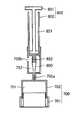
図8は、本実施形態に係る検体採取器具を示す概略断面図である。本実施形態に係る検体採取器具もまた、第1の実施形態と同様、液状検体を吸収保持する吸収体から、液状検体を精度良く定量しながら採取できる器具であり、2つのピストン機構(圧搾部700としてのピストン機構と定量部800としてのピストン機構)を収容部900で接続したような簡易な構造を有している。<Second Embodiment>
FIG. 8 is a schematic cross-sectional view showing the sample collecting device according to the present embodiment. Similarly to the first embodiment, the sample collection device according to this embodiment is a device that can collect a liquid sample while accurately quantifying it from an absorber that absorbs and holds the liquid sample. It has a simple structure in which a piston mechanism as 700 and a piston mechanism as the
本実施形態に係る検体採取器具と第1の実施形態に係る検体採取器具との間の構造上の主な相違点は、本実施形態では、圧搾部700と定量部800の中空部におけるプランジャが挿入される側とは反対側の開口が同じ側を向くのではなく、互いに対向するように、圧搾部700と定量部800を上下に配置している点である。定量部800のシリンダ(第2シリンダ802)の一部は、圧搾部700のシリンダ(第1シリンダ702)に差し込まれている。 The main difference in structure between the sample collection device according to the present embodiment and the sample collection device according to the first embodiment is that the plunger in the hollow portion of the squeezing
圧搾部700は、第1中空部を有する第1シリンダ702、及び、第1中空部に挿入される第1プランジャ701からなる。本実施形態において第1中空部は、第1プランジャ701が挿入される側から順に、第1チャンバ751、及び、第1チャンバ751に連結経路702aを介して連結される第2チャンバ752から構成されており、第3チャンバを有しない。例えば、台の上に置かれた第1プランジャ701に対し、第1シリンダ702を押し込むことにより、液状検体を吸収保持する吸収体が圧搾され、吸収体から液状検体が取り出される。第1プランジャ701の周縁部には、押し込まれた第1シリンダ702を挿入するための凹部が形成されている。 The
本実施形態では、第1プランジャ701ではなく、第1シリンダ702に、第1中空部と採取器具外部とを連通する開口からなる、第1中空部内の空気を排出するための空気排出口702bを設けている。 In the present embodiment, not the
定量部800は、第2中空部851を有する第2シリンダ802、及び、第2中空部851に挿入される第2プランジャ801からなる。第2シリンダ802には、その先端に、第2中空部851の狭部852を形成する針部が設けられており、これに収容部900が取り付けられる。第2シリンダ802の第2中空部851に挿入された第2プランジャ801を引くことにより、吸収体から取り出された液状検体のうちの所定量が第1中空部(より具体的には第2チャンバ752)から収容部900内に導入される。 The fixed
収容部900は、第2シリンダ802の針部に取り付けられることにより、第2シリンダ802の第2中空部851と空間的に接続されている。また、収容部900は、第1シリンダ702の第2チャンバ752内に配置されているので、第1中空部(第2チャンバ752)とも空間的に接続されている。本実施形態において収容部900は、ピペットチップ等のプラスチック部材である。 The
次に、図9を参照しながら、本実施形態に係る検体採取器具の使用方法について説明する。本実施形態に係る検体採取器具によれば、第1の実施形態と同様、極めて簡便な操作で液状検体を精度良く、また、安全に、衛生的に定量採取できる。なお以下では、液状検体が唾液である場合を例に挙げて検体採取器具の使用方法を説明するが、液状検体は唾液に限定されるものではない。 Next, a method for using the sample collecting device according to the present embodiment will be described with reference to FIG. According to the sample collection device according to the present embodiment, as in the first embodiment, a liquid sample can be quantitatively collected with high accuracy, safety, and hygiene by an extremely simple operation. In the following, the method of using the sample collecting device will be described by taking the case where the liquid sample is saliva as an example, but the liquid sample is not limited to saliva.
(A)圧搾工程
まず本工程において、口に含ませることにより唾液を吸収させた唾液採取用の吸収体400を、第1シリンダ702の第1チャンバ751に入れ〔図9(a)〕、台の上に置かれた第1プランジャ701に対し、第1シリンダ702を押し込むことにより、吸収体400を圧搾し、吸収体400から唾液450を取り出す〔図9(b)〕。取り出すべき唾液450の量を明確に把握できるよう、第1の実施形態と同様、第2チャンバ752にマーカー(目印となるライン)を付しておくとよい。第2チャンバ752への唾液450の導入に伴い、第1中空部内の空気は、空気排出口702bから排出される。(A) squeezing step First, in this step, the saliva collecting
(B)定量工程
上記圧搾工程(A)に続き、本工程では、第2プランジャ801を引くことによって、第2チャンバ752に保持された唾液450のうちの所定量を第1中空部から排出させ、収容部900内に引き込むことにより定量を行う〔図9(c)〕。定量されるべき唾液450の量を明確に把握できるよう、収容部900にマーカー(目印となるライン)を付しておくとよい。収容部900内に収容され得る唾液量は、収容部900の内容積によって調節することができる。本実施形態においても同様に、図3に示されるような第2プランジャを用いることができる。(B) Determination step Following the above-described pressing step (A), in this step, by pulling the
(C)取り出し工程
最後に、本工程において、定量部800及び収容部900を圧搾部700から取り外し〔図9(d)〕、第2プランジャ801を最後まで押して、定量された唾液を収容部900から取り出す〔図9(e)〕。例えば、収容部900の先端から、唾液分析を行う分析チップ(バイオチップ)や分析装置の検体注入口に直接滴下する。(C) Extraction process Finally, in this process, the fixed
100,800 圧搾部、101,701 第1プランジャ、101a 第1プランジャの先端部、102,702 第1シリンダ、151,751 第1チャンバ、152,752 第2チャンバ、153 第3チャンバ、160 第1狭窄部、170 第2狭窄部、200,800 定量部、201,801 第2プランジャ、201a 第2プランジャの先端部、202,802 第2シリンダ、205 凹部、205a 空間部、251,851 第2中空部、852 狭部、300,900 収容部、400 吸収体、450 唾液、702a 連結経路、702b 空気排出口。 100,800 Pressing part, 101,701 1st plunger, 101a First plunger, 102,702 1st cylinder, 151,751 1st chamber, 152,752 2nd chamber, 153 3rd chamber, 160 1st Stenosis part, 170 second stenosis part, 200,800 quantification part, 201,801 second plunger, 201a tip of second plunger, 202,802 second cylinder, 205 recess, 205a space part, 251,851 second hollow Part, 852 narrow part, 300,900 accommodating part, 400 absorber, 450 saliva, 702a connection path, 702b air outlet.
Claims (4)
Translated fromJapanese第2中空部を有する第2シリンダ、及び、第2中空部に挿入される第2プランジャから構成されており、前記吸収体から取り出された液状検体のうちの所定量を第1中空部から排出させるための定量部と、
第1中空部及び第2中空部と空間的に接続されており、第1中空部から排出された所定量の液状検体を収容するための、第1中空部に対して着脱自在に接続されている収容部と、を含む検体採取器具。A first cylinder having a first hollow portion, and a squeezing portion comprising a first plunger for squeezing an absorbent that absorbs and holds the liquid specimen, and is taken in the first hollow section, and for taking out the liquid specimen; ,
It is comprised from the 2nd cylinder which has a 2nd hollow part, and the 2nd plunger inserted in a 2nd hollow part, The predetermined amount of the liquid sample taken out from the said absorber is discharged | emitted from a 1st hollow part A quantitative unit for
It is spatially connected to the first hollow part and the second hollow part, and isdetachably connected to the first hollow part for containing a predetermined amount of liquid specimen discharged fromthe first hollow part. A sample collection device including a storage portion.
第2チャンバの断面積は、第1チャンバの断面積より小さい請求項1又は2に記載の検体採取器具。The first hollow portion includes, in order from the side where the first plunger is inserted, a first chamber and a second chamber connected to the first chamber,
The specimen collection instrument according to claim1 or 2 , wherein the cross-sectional area of the second chamber is smaller than the cross-sectional area of the first chamber.
第3チャンバの断面積は、第2チャンバの断面積より小さい請求項3に記載の検体採取器具。The first hollow portion further includes a third chamber connected to the opposite side of the second chamber to the side to which the first chamber is connected,
The specimen collecting instrument according to claim3 , wherein a cross-sectional area of the third chamber is smaller than a cross-sectional area of the second chamber.
Priority Applications (1)
| Application Number | Priority Date | Filing Date | Title |
|---|---|---|---|
| JP2012085188AJP6018779B2 (en) | 2012-04-04 | 2012-04-04 | Sample collection device |
Applications Claiming Priority (1)
| Application Number | Priority Date | Filing Date | Title |
|---|---|---|---|
| JP2012085188AJP6018779B2 (en) | 2012-04-04 | 2012-04-04 | Sample collection device |
Publications (2)
| Publication Number | Publication Date |
|---|---|
| JP2013213784A JP2013213784A (en) | 2013-10-17 |
| JP6018779B2true JP6018779B2 (en) | 2016-11-02 |
Family
ID=49587194
Family Applications (1)
| Application Number | Title | Priority Date | Filing Date |
|---|---|---|---|
| JP2012085188AActiveJP6018779B2 (en) | 2012-04-04 | 2012-04-04 | Sample collection device |
Country Status (1)
| Country | Link |
|---|---|
| JP (1) | JP6018779B2 (en) |
Families Citing this family (1)
| Publication number | Priority date | Publication date | Assignee | Title |
|---|---|---|---|---|
| CN108458896B (en)* | 2017-02-20 | 2024-11-26 | 深圳市为康科技有限公司 | Liquid specimen collection device |
Family Cites Families (12)
| Publication number | Priority date | Publication date | Assignee | Title |
|---|---|---|---|---|
| JPS4330479Y1 (en)* | 1968-07-10 | 1968-12-12 | ||
| JPH0610864U (en)* | 1991-12-16 | 1994-02-10 | 株式会社ニッポンジーン | Urine collection metering drip device |
| JPH07270409A (en)* | 1994-03-31 | 1995-10-20 | Toto Ltd | Parallel syringe pumps for urine analysis |
| US7879293B2 (en)* | 2001-09-28 | 2011-02-01 | Orasure Technologies, Inc. | Sample collector and test device |
| US6820506B2 (en)* | 2002-03-27 | 2004-11-23 | 3M Innovative Properties Company | Multi-chambered pump-valve device |
| GB2391813B (en)* | 2002-08-14 | 2006-03-29 | Cozart Bioscience Ltd | An oral fluid collection, transfer and transportation device and method |
| JP2004237150A (en)* | 2003-02-03 | 2004-08-26 | Murata Mfg Co Ltd | Constant quantity discharger |
| NZ547173A (en)* | 2003-11-14 | 2009-09-25 | Inverness Medical Switzerland | Fluid sample analysis device with sealable sample storage reservoir |
| JP4489609B2 (en)* | 2005-01-27 | 2010-06-23 | 株式会社エンプラス | Liquid mixing device |
| JP4988382B2 (en)* | 2007-02-28 | 2012-08-01 | ジーエルサイエンス株式会社 | Solid phase extraction device for sample solution |
| EP2146911A4 (en)* | 2007-04-16 | 2010-10-27 | Orasure Technologies Inc | Sample collector |
| WO2009037810A1 (en)* | 2007-09-18 | 2009-03-26 | Panasonic Corporation | Measurement device, measurement instrument and method, and sampling method |
- 2012
- 2012-04-04JPJP2012085188Apatent/JP6018779B2/enactiveActive
Also Published As
| Publication number | Publication date |
|---|---|
| JP2013213784A (en) | 2013-10-17 |
Similar Documents
| Publication | Publication Date | Title |
|---|---|---|
| CA2563274C (en) | Specimen collecting, processing and analytical assembly | |
| NO320168B1 (en) | Process for painting a concentration of an analyte in a sample of a biological fluid. | |
| NO320325B1 (en) | Hollow, cone-shaped reagent test device | |
| NO320326B1 (en) | Templates, and sets, for painting analyte concentration in a sample of biological fluid. | |
| JP2009122082A (en) | Blood dilution meter | |
| JP6836012B2 (en) | Analyzer cartridge with capillary wiper | |
| WO2008122908A1 (en) | Method and device for gathering a fluid sample for screening purposes | |
| US7318359B2 (en) | Sampling means and system for testing a sample liquid | |
| JP2012132897A (en) | Specimen sampling tool and specimen sampling kit | |
| US20240426820A1 (en) | Apparatus and method for diagnostic testing | |
| US20240264153A1 (en) | Kit for urine testing | |
| Fernandes et al. | Reduction of blood volume required to perform paper-based hematocrit assays guided by device design | |
| JP2020510848A (en) | Fluid collection unit and related devices and methods | |
| JP6018779B2 (en) | Sample collection device | |
| JP5416227B2 (en) | Collection and assay devices for biological fluids | |
| US20240042449A1 (en) | Test device, test method and manufacturing method for test device for carrying out a test directed to the detection of an organic structure | |
| JP2016538551A (en) | In-vitro automatic diagnosis method | |
| KR20230118885A (en) | developing solution bottle | |
| JP4401845B2 (en) | Sample test container set and sample test kit | |
| JP2012026997A (en) | Method and instrument for sampling, diluting and dispensing minute specimen by capillary | |
| Yamaguchi et al. | Disposable collection kit for rapid and reliable collection of saliva | |
| US20210197193A1 (en) | Parts for diagnostic devices | |
| JP6389870B2 (en) | Apparatus for collecting fluid sample, receptacle receiving the apparatus, assembly for collecting fluid sample, and method for collecting fluid sample | |
| JP2010271040A (en) | Sampling method, measuring method and measuring apparatus | |
| CN113349771A (en) | Liquid sampling device and method |
Legal Events
| Date | Code | Title | Description |
|---|---|---|---|
| A621 | Written request for application examination | Free format text:JAPANESE INTERMEDIATE CODE: A621 Effective date:20150406 | |
| A711 | Notification of change in applicant | Free format text:JAPANESE INTERMEDIATE CODE: A711 Effective date:20151007 | |
| A521 | Request for written amendment filed | Free format text:JAPANESE INTERMEDIATE CODE: A821 Effective date:20151007 | |
| A977 | Report on retrieval | Free format text:JAPANESE INTERMEDIATE CODE: A971007 Effective date:20160129 | |
| A131 | Notification of reasons for refusal | Free format text:JAPANESE INTERMEDIATE CODE: A131 Effective date:20160223 | |
| A521 | Request for written amendment filed | Free format text:JAPANESE INTERMEDIATE CODE: A523 Effective date:20160329 | |
| TRDD | Decision of grant or rejection written | ||
| A01 | Written decision to grant a patent or to grant a registration (utility model) | Free format text:JAPANESE INTERMEDIATE CODE: A01 Effective date:20160906 | |
| A61 | First payment of annual fees (during grant procedure) | Free format text:JAPANESE INTERMEDIATE CODE: A61 Effective date:20161003 | |
| R150 | Certificate of patent or registration of utility model | Ref document number:6018779 Country of ref document:JP Free format text:JAPANESE INTERMEDIATE CODE: R150 | |
| R250 | Receipt of annual fees | Free format text:JAPANESE INTERMEDIATE CODE: R250 | |
| R250 | Receipt of annual fees | Free format text:JAPANESE INTERMEDIATE CODE: R250 | |
| R250 | Receipt of annual fees | Free format text:JAPANESE INTERMEDIATE CODE: R250 | |
| R250 | Receipt of annual fees | Free format text:JAPANESE INTERMEDIATE CODE: R250 | |
| R250 | Receipt of annual fees | Free format text:JAPANESE INTERMEDIATE CODE: R250 | |
| R250 | Receipt of annual fees | Free format text:JAPANESE INTERMEDIATE CODE: R250 |