JP6017911B2 - Artificial dialysis water production equipment for personal dialysis - Google Patents
Artificial dialysis water production equipment for personal dialysisDownload PDFInfo
- Publication number
- JP6017911B2 JP6017911B2JP2012220106AJP2012220106AJP6017911B2JP 6017911 B2JP6017911 B2JP 6017911B2JP 2012220106 AJP2012220106 AJP 2012220106AJP 2012220106 AJP2012220106 AJP 2012220106AJP 6017911 B2JP6017911 B2JP 6017911B2
- Authority
- JP
- Japan
- Prior art keywords
- water
- dialysis
- production apparatus
- electrolyzed
- artificial
- Prior art date
- Legal status (The legal status is an assumption and is not a legal conclusion. Google has not performed a legal analysis and makes no representation as to the accuracy of the status listed.)
- Active
Links
- XLYOFNOQVPJJNP-UHFFFAOYSA-NwaterSubstancesOXLYOFNOQVPJJNP-UHFFFAOYSA-N0.000titleclaimsdescription197
- 238000004519manufacturing processMethods0.000titleclaimsdescription84
- 238000000502dialysisMethods0.000titleclaimsdescription65
- UFHFLCQGNIYNRP-UHFFFAOYSA-NHydrogenChemical compound[H][H]UFHFLCQGNIYNRP-UHFFFAOYSA-N0.000claimsdescription29
- 239000001257hydrogenSubstances0.000claimsdescription29
- 229910052739hydrogenInorganic materials0.000claimsdescription29
- 238000005868electrolysis reactionMethods0.000claimsdescription24
- 239000012528membraneSubstances0.000claimsdescription9
- 238000001179sorption measurementMethods0.000claimsdescription9
- 238000001223reverse osmosisMethods0.000claimsdescription5
- 239000008399tap waterSubstances0.000description11
- 235000020679tap waterNutrition0.000description11
- OKTJSMMVPCPJKN-UHFFFAOYSA-NCarbonChemical compound[C]OKTJSMMVPCPJKN-UHFFFAOYSA-N0.000description10
- 239000000385dialysis solutionSubstances0.000description3
- 239000003673groundwaterSubstances0.000description3
- 230000001603reducing effectEffects0.000description3
- ZAMOUSCENKQFHK-UHFFFAOYSA-NChlorine atomChemical compound[Cl]ZAMOUSCENKQFHK-UHFFFAOYSA-N0.000description2
- KFSLWBXXFJQRDL-UHFFFAOYSA-NPeracetic acidChemical compoundCC(=O)OOKFSLWBXXFJQRDL-UHFFFAOYSA-N0.000description2
- 230000003078antioxidant effectEffects0.000description2
- 239000000460chlorineSubstances0.000description2
- 229910052801chlorineInorganic materials0.000description2
- BASFCYQUMIYNBI-UHFFFAOYSA-NplatinumChemical compound[Pt]BASFCYQUMIYNBI-UHFFFAOYSA-N0.000description2
- 239000008234soft waterSubstances0.000description2
- OYPRJOBELJOOCE-UHFFFAOYSA-NCalciumChemical compound[Ca]OYPRJOBELJOOCE-UHFFFAOYSA-N0.000description1
- JLVVSXFLKOJNIY-UHFFFAOYSA-NMagnesium ionChemical compound[Mg+2]JLVVSXFLKOJNIY-UHFFFAOYSA-N0.000description1
- 229910021536ZeoliteInorganic materials0.000description1
- 239000003463adsorbentSubstances0.000description1
- QVGXLLKOCUKJST-UHFFFAOYSA-Natomic oxygenChemical compound[O]QVGXLLKOCUKJST-UHFFFAOYSA-N0.000description1
- 230000001580bacterial effectEffects0.000description1
- 229910052791calciumInorganic materials0.000description1
- 239000011575calciumSubstances0.000description1
- 208000020832chronic kidney diseaseDiseases0.000description1
- 208000022831chronic renal failure syndromeDiseases0.000description1
- 238000011109contaminationMethods0.000description1
- 238000010586diagramMethods0.000description1
- HNPSIPDUKPIQMN-UHFFFAOYSA-Ndioxosilane;oxo(oxoalumanyloxy)alumaneChemical compoundO=[Si]=O.O=[Al]O[Al]=OHNPSIPDUKPIQMN-UHFFFAOYSA-N0.000description1
- 230000002070germicidal effectEffects0.000description1
- 229910001425magnesium ionInorganic materials0.000description1
- 238000005259measurementMethods0.000description1
- 229910052751metalInorganic materials0.000description1
- 239000002184metalSubstances0.000description1
- 239000008239natural waterSubstances0.000description1
- 239000001301oxygenSubstances0.000description1
- 229910052760oxygenInorganic materials0.000description1
- 229910052697platinumInorganic materials0.000description1
- 230000008092positive effectEffects0.000description1
- 238000011045prefiltrationMethods0.000description1
- 239000002994raw materialSubstances0.000description1
- 150000003839saltsChemical class0.000description1
- 239000000243solutionSubstances0.000description1
- 239000003206sterilizing agentSubstances0.000description1
- 239000008400supply waterSubstances0.000description1
- 229920003002synthetic resinPolymers0.000description1
- 239000000057synthetic resinSubstances0.000description1
- 230000001225therapeutic effectEffects0.000description1
- 239000010457zeoliteSubstances0.000description1
Images


Landscapes
- Separation Using Semi-Permeable Membranes (AREA)
- Treatment Of Water By Ion Exchange (AREA)
- Water Treatment By Electricity Or Magnetism (AREA)
- Water Treatment By Sorption (AREA)
- Medicinal Preparation (AREA)
- External Artificial Organs (AREA)
Description
Translated fromJapanese本発明は、医療施設での個別透析および在宅で慢性腎不全患者が使用することができる、一人または二人用として好適な個人透析用の人工透析用水製造装置と、それを用いた透析液製造装置に関する。 The present invention relates to an apparatus for producing artificial dialysis water for personal dialysis suitable for one or two persons that can be used by a patient with chronic renal failure at individual dialysis at home or at home, and dialysis fluid production using the apparatus. Relates to the device.
従来、電解水製造装置と逆浸透膜装置(RO装置)を組み合わせた透析用水および透析液の製造装置が知られている(特許文献1)。
これらは医療施設において、多人数の患者の治療に対応するための装置であることから、高い製造能力を有しているものであり、電解水製造装置への原水(水道水)供給量は500L/hrを超える量となる。そのため、特許文献1の人工透析用水製造装置では、4台の電解水製造装置を用いた水素含有透析用水の製造例が示されている。
また、特許文献2に示されるように、従来の電解水製造装置は電解効率を高めるために、供給水の電気伝導度を100μS/cm以上とするようにイオン分を加えて所望する溶存水素濃度を達成しているため、使用する原水に制限を受けるものであった。2. Description of the Related Art Conventionally, a dialysis water and dialysate manufacturing apparatus is known that combines an electrolyzed water manufacturing apparatus and a reverse osmosis membrane apparatus (RO apparatus) (Patent Document 1).
Since these are devices for treating a large number of patients in a medical facility, they have a high production capacity, and the amount of raw water (tap water) supplied to the electrolyzed water production device is 500L. The amount exceeds / hr. Therefore, in the artificial dialysis water production apparatus of
Moreover, as shown in
医療施設における個別透析や家庭での透析治療においては、大型装置は必要ではなく、小型の装置であることが望まれる。
また、地域によってはイオン分の少ない低電導度の水道水等を原水として使用する場合もあるため、低電導度の原水でも十分な治療効果をもたらす溶存水素濃度が得られるような電解効率の高い電解水製造装置が求められている。In individual dialysis in a medical facility and dialysis treatment at home, a large device is not necessary, and a small device is desired.
Also, depending on the region, tap water with low conductivity and low conductivity may be used as raw water, so the electrolytic efficiency is high so that dissolved hydrogen concentration can be obtained with sufficient therapeutic effect even with low conductivity raw water. There is a need for an electrolyzed water production apparatus.
本発明は、一人または二人用として好適な個人透析用の小型で電解効率の高い溶存水素含有人工透析用水製造装置と、それを用いた透析液製造装置を提供することを課題とする。 It is an object of the present invention to provide a small-sized and highly electrolyzed dissolved hydrogen-containing artificial dialysis water production apparatus suitable for one or two persons, and a dialysis fluid production apparatus using the same.
本発明は、課題の解決手段として、
軟水器、吸着装置、電解水製造装置、逆浸透膜装置(RO装置)およびRO装置処理水(人工透析用水)タンクを有する個人透析用の人工透析用水製造装置であって、
前記電解水製造装置が、
陰極(−)と陽極(+)が、合計7枚以上で、交互に配置されており、
隣接する陰極(−)と陽極(+)の間隔が均等間隔で、かつ3〜5mmの範囲であり、
陰極(−)と陽極(+)の間に隔膜が配置された電気分解槽を有しているものである、個人透析用の人工透析用水製造装置と、それを用いた透析液製造装置を提供する。As a means for solving the problems, the present invention
A water production device for artificial dialysis for personal dialysis having a water softener, an adsorption device, an electrolyzed water production device, a reverse osmosis membrane device (RO device) and an RO device treated water (water for artificial dialysis) tank,
The electrolyzed water production apparatus is
The cathode (-) and anode (+) are arranged in total of 7 or more,
The interval between the adjacent cathode (-) and anode (+) is a uniform interval and is in the range of 3-5 mm,
Providing an artificial dialysis water production apparatus for personal dialysis and an dialysis fluid production apparatus using the electrolysis tank in which a diaphragm is disposed between a cathode (−) and an anode (+) To do.
本発明の個人透析用の人工透析用水製造装置によれば、小型で低電導度の供給水を使用した場合でも溶存水素濃度の高い人工透析用水を一人または二人用として、適量を製造することができる。 According to the artificial dialysis water production apparatus for personal dialysis of the present invention, even when small and low-conductivity supply water is used, artificial dialysis water having a high dissolved hydrogen concentration is used for one or two persons, and an appropriate amount is produced. Can do.
<個人透析用の人工透析用水製造装置>
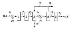
図1により説明する。
原水(水道水または地下水)と軟水器1は、原水ライン11で接続されている。このとき、家庭での使用の場合、軟水器1の原水入口と蛇口を原水ライン11で接続して使用することができる。
原水は、原水ライン11に設置された原水ポンプ21を駆動させて軟水器1に送られる。
なお、水道の蛇口に接続した場合には、水圧を利用することで原水ポンプ21を省略することもできる。
また、必要に応じて軟水器1の前にプレフィルターを設置することができる。<Water production equipment for artificial dialysis for personal dialysis>
This will be described with reference to FIG.
The raw water (tap water or groundwater) and the
The raw water is sent to the
In addition, when connected to the faucet of a water supply, the raw |
Moreover, a pre filter can be installed in front of the
軟水器1は、原水中の硬度成分(カルシウム、マグネシウムイオン等)の濃度を低減させるためのものである。
軟水器1は、市販の軟水器を使用することができる。
軟水器1で硬度成分の濃度が低減された水は、ライン12から吸着装置2に送られる。The
As the
The water whose hardness component concentration is reduced in the
吸着装置2は、ケース内に活性炭、ゼオライト等の吸着剤が充填されたものである。
吸着装置2は、残留塩素等を吸着除去するための装置である。
吸着装置2で残留塩素等が除去された水は、ライン13から電解水製造装置3に送られる。The
The
The water from which residual chlorine and the like have been removed by the
電解水製造装置3は、軟水装置1と吸着装置2で処理した前処理水を電気分解して、電解陰極水と電解陽極水を得るためのものである。
電解水製造装置自体は公知のものであるが(例えば、特許文献1、2参照)、本発明で使用する電解水製造装置3は、一人または二人用の個人透析用の人工透析用水製造装置として好適な構造となっている。
電解水製造装置3は、電解水製造装置と、軟水器1および吸着装置2およびRO装置が一体にされた装置にすることもできる。The electrolyzed
Although the electrolyzed water production apparatus itself is known (for example, see
The electrolyzed
本発明で使用することができる電解水製造装置3を図2により説明する。
電解水製造装置3は、電気分解槽31内にライン13から送られた前処理水が満たされており、その中に浸漬された状態で、陰極32が4枚と陽極33が3枚(合計7枚)が交互に、かつ両端部側が陰極32になるように配置されている。
また、一定回数もしくは一定時間使用ごとに電極板の極性を反転して、前記の一定回数もしくは一定時間の運転中に電解陰極水側の電極に付着したスケールを電解陽極水側に排出させることもできる。
隣接する陰極32と陽極33の間隔は均等間隔であり、かつ3〜5mmの範囲、好ましくは3〜4.5mmの範囲である。
陰極32と陽極33の間には隔膜34が、陰極32と陽極33の間を等分に区切るように配置されており、陰極32が配置された陰極槽41〜43、62と陽極33が配置された陽極槽51、52、61に分離されている。
なお、陰極と陽極の間と陽極と陰極の間にて電解が生じるため、図2では、7枚の電極で挟まれた合計6のゾーン(電解槽)で電解が生じることになる。6つの電解槽はそれぞれ隔膜34で2つに仕切られているので、6つの電解槽は6つの陰極セルと6つの陽極セルからなっている。An electrolyzed
In the electrolyzed
In addition, the polarity of the electrode plate is reversed every use for a certain number of times or for a certain period of time, and the scale adhering to the electrode on the electrolytic cathodic water side during the operation for a certain number of times or for a certain time can be discharged to the electrolytic anodic water side. it can.
The interval between the
A
Since electrolysis occurs between the cathode and the anode and between the anode and the cathode, in FIG. 2, electrolysis occurs in a total of six zones (electrolyzers) sandwiched between seven electrodes. Since each of the six electrolytic cells is divided into two by the
電極板(陰極と陽極)の大きさは、電解水製造装置3の大きさに合わせて調整する。本発明の人工透析用水製造装置は個人透析用であり、25〜80L/hr量(一人用または二人用として好適な量)の透析用水が調製されれば流量的には十分であるため、電極板も医療施設で一般的に使用されている電解水製造装置と比べると小型になる。
図2では陰極32と陽極33が合計で7枚であるが、8枚以上の枚数にすることもできる。前記の通り、本発明の電解装置で調製される必要水量が小さいため、水素を発生させる陰極槽における電解条件(電流密度、槽内の滞留時間)も、電極板面積、陰極槽内流量に応じて、適宜、設定される。The size of the electrode plates (cathode and anode) is adjusted according to the size of the electrolyzed
In FIG. 2, the total number of the
電解水製造装置3の運転により陰極槽41〜43、62では、溶存水素濃度の高い電解陰極水が得られ、陽極槽51、52、61では、相対的に溶存水素濃度の低い電解陽極水が得られる。
電解陰極水量と電解陽極水量の生成量は、電解陰極水量の方が多くなるようにすることが望ましく、例えば電解陰極水量:電解陽極水量=4〜6:1にすることができる。
電解陰極水は、ポンプ22を駆動させてライン14からRO装置4に送られ、電解陽極水はライン15から排出される。
なお、電解水製造装置3とポンプ22の間に電解陰極水を貯水するための電解陰極水タンクを設置して、電解陰極水タンクに貯水した電解陰極水をRO装置4に送るようにすることもできる。By operation of the electrolyzed
It is desirable that the amount of electrolytic cathodic water and electrolytic anodic water be larger than the amount of electrolytic cathodic water, for example, the amount of electrolytic cathodic water: electrolytic anodic water = 4 to 6: 1.
The electrolytic cathodic water is sent to the
An electrolytic cathodic water tank for storing electrolytic cathodic water is installed between the electrolyzed
RO装置4は公知のものを用いることができ、例えば、ダイセン・メンブレン・システムズ株式会社より販売されている、装置型式VCR20シリーズ、を用いることができる。 As the
RO装置4で得られた透過水は、ライン16から透過水タンク(RO水タンク)5に送られて貯水される。
個人透析による人工透析は、多人数透析と比べると使用頻度が低く、RO装置の停止期間が長くなり、外部からの菌汚染を生じる可能性があるため、必要に応じてRO装置4の出口にUF膜モジュール(UF装置)を設けて、UF膜処透過水をRO水タンク(人工透析液用水タンク)5に貯水することもできる。
RO装置4では、溶存水素濃度の高い電解陰極水を処理しているため、RO水中の溶存水素濃度も高くなっており、一方、残存するイオン成分がさらに除去されており、電気伝導度は1〜20μS程度にまで低下されている。
RO水タンク5内のRO水は、ライン17から採水されて人工透析液用水として使用される。
RO装置3で得られた濃縮水は、ライン18から電解水製造装置3に送られて再度電気分解処理してもよいし、ライン19から排出されるようにしてもよい。The permeated water obtained by the
Artificial dialysis by personal dialysis is less frequently used than multi-person dialysis, and the stop period of the RO device becomes longer and may cause bacterial contamination from the outside. A UF membrane module (UF device) may be provided, and the UF membrane treated permeated water may be stored in the RO water tank (artificial dialysate water tank) 5.
In the
The RO water in the
The concentrated water obtained by the
図1に示す製造装置の各ラインには、必要に応じて電磁弁等からなる開閉弁、流量計、温度計等を設置することができる。
図1に示す製造装置は、適宜清浄水で通水洗浄することができるほか、RO装置4、タンク5および各ラインは、過酢酸水溶液等の殺菌剤で殺菌・洗浄することもできる。また、電解水製造装置3を除く前記装置類・各ラインは加熱殺菌することができる。さらに、タンク5には、UV殺菌灯を設けてもよい。Each line of the manufacturing apparatus shown in FIG. 1 can be provided with an on-off valve, a flow meter, a thermometer, or the like made up of an electromagnetic valve or the like as necessary.
The manufacturing apparatus shown in FIG. 1 can be appropriately washed with clean water, and the
図3により本発明の製造装置の好ましい実施形態を説明する。
本発明の製造装置は、個人透析用の人工透析用水製造装置であることから、狭いスペースに設置することが多くなる。
図3は、本発明の製造装置を個人用としてより使い易いようにまとめた好ましい実施形態を示している。
個人透析用の人工透析用水製造装置10は、金属製乃至は合成樹脂製の外側ケース11内に、原水源(例えば、水道管)と接続された軟水装置1、吸着装置2、電解水製造装置3、電解陰極水タンク12、RO装置4、UF装置13が配置され、原水ポンプ21、ROポンプ22が配置されている。
RO水タンク(人工透析液用水タンク)5は、ケース11の外側にケース11と一体にかつ着脱自在に設置されている。
破線で示した吸着装置2とROポンプ22は、反対側に配置されていることを示している。
図3で示す人工透析用水製造装置10は、個人透析用としての十分な製造能力を維持したままで、縦幅300〜500mm、横幅900〜1100mmm、高さが950〜1200mm程度の大きさにすることができる。A preferred embodiment of the production apparatus of the present invention will be described with reference to FIG.
Since the production apparatus of the present invention is an artificial dialysis water production apparatus for personal dialysis, it is often installed in a narrow space.
FIG. 3 shows a preferred embodiment in which the manufacturing apparatus of the present invention is summarized for easier use for personal use.
An artificial dialysis
The RO water tank (artificial dialysate water tank) 5 is installed outside the
The adsorbing
The
本発明の製造装置は医療施設の個別透析や、家庭での在宅透析に使用できるものであるが、地域によっては原水となる水道水や地下水の電気伝導度が異なる場合がある。
本発明の製造装置で使用する電解水製造装置3は、電極枚数が7枚以上と多く、電極間の距離が小さいことから、電気伝導度が低い原水でも使用することができ、例えば、電気伝導度が40〜100μS/cmと100μS/cm以下の低電導度の原水でも、十分な濃度の溶存水素を含む電解陰極水を製造することができる。
また、電解電圧を70Vまで高めること、電極枚数を増やすことで陰極槽数を増やし、陰極槽当たりの供給流量を相対的に少なくすることにより陰極槽内滞留時間を長くして、より電解効率を高め、低電導度の原水でも溶存水素量を増やすことができる。
本発明の電解装置においては、電解電圧を高めることにより、電流密度は、0.5A/dm2〜2.0A/dm2、好ましくは0.6A/dm2〜1.5A/dm2の範囲を設定でき、また、陰極槽内滞留時間を0.4〜2.3秒、好ましくは1〜2秒の範囲で設定することにより、効率よく高濃度の溶存水素水を製造することができる。The production apparatus of the present invention can be used for individual dialysis in a medical facility or home dialysis at home, but the electric conductivity of tap water or groundwater as raw water may vary depending on the region.
The electrolyzed
Also, increasing the electrolysis voltage to 70V, increasing the number of electrodes, increasing the number of cathode cells, and relatively reducing the supply flow rate per cathode cell, thereby prolonging the residence time in the cathode cell and further increasing the electrolysis efficiency. It is possible to increase the amount of dissolved hydrogen even in raw water with high conductivity and low conductivity.
In the electrolysis apparatus of the present invention, by increasing the electrolysis voltage, the current density can be set in the range of 0.5 A /
本発明の製造装置は、原水として家庭の水道水や地下水を使用した場合、さらに上記した電気伝導度の低い原水を使用した場合においても、溶存水素濃度が100〜1600ppbの人工透析用水を25〜80L/hr量(一人用または二人用として好適な量)製造することができる。
また、本発明の電解効率の高い電解装置を適用し、軟水器、活性炭、逆浸透膜装置と一体化することにより、本発明の透析用水製造装置全体が個人透析用に適応した小型装置として、製作することが可能となる。In the production apparatus of the present invention, when domestic tap water or groundwater is used as raw water, and even when the above-described raw water with low electrical conductivity is used, 25 to 25 water for artificial dialysis having a dissolved hydrogen concentration of 100 to 1600 ppb is used. An amount of 80 L / hr (a quantity suitable for one person or two persons) can be produced.
In addition, by applying the electrolyzer with high electrolysis efficiency of the present invention and integrating it with a water softener, activated carbon, and reverse osmosis membrane device, the entire dialysis water production apparatus of the present invention is adapted for personal dialysis, It becomes possible to produce.
本発明の製造装置により得られた溶存水素濃度の高い人工透析用水と必要成分を混合して得られた人工透析液は、抗酸化作用が高く、活性酸素種に対して抗酸化作用(還元作用)を発揮することで、人工透析患者に好ましい影響を与えることが期待される。 Artificial dialysate obtained by mixing artificial dialysis water with a high dissolved hydrogen concentration obtained by the production apparatus of the present invention and necessary components has high antioxidant action and has antioxidative action (reducing action) against active oxygen species. ) Is expected to have a positive effect on dialysis patients.
<透析液製造装置>
本発明の透析液製造装置は、上記した個人透析用の人工透析用水製造装置と透析液を調製する手段を有するものである。
透析液を調製する手段は、人工透析用水と周知の透析原剤(例えば、特許第3436912号公報に記載されているもの)を混合する手段である。<Dialysate production equipment>
The dialysate production apparatus of the present invention has the above-described artificial dialysis water production apparatus for personal dialysis and means for preparing a dialysate.
The means for preparing the dialysate is a means for mixing artificial dialysis water and a known dialysis raw material (for example, those described in Japanese Patent No. 3436912).
図1に示す製造装置で、電解水製造装置3として図2に示すものを備えた製造装置を使用して、室温(20〜25℃)で人工透析用水を製造した。
使用した装置の詳細は次のとおり。In the production apparatus shown in FIG. 1, water for artificial dialysis was produced at room temperature (20 to 25 ° C.) using a production apparatus having the electrolysis
Details of the equipment used are as follows.
軟水器:オートトロール社のATS-18
活性炭(吸着装置):繊維状活性炭
RO装置:ダイセン・メンブレン・システムズ(株)のVCR-42S(4インチスパイラルモジュール・2本;食塩除去率が99%のもの)
溶存水素濃度の測定:東亜ディーケーケー(株)のポータブル溶存水素計DH-35AWater softener: Autotrol ATS-18
Activated carbon (adsorption device): Fibrous activated carbon RO device: VCR-42S from Daisen Membrane Systems Co., Ltd. (4 inch spiral module, 2; 99% salt removal rate)
Measurement of dissolved hydrogen concentration: Portable dissolved hydrogen meter DH-35A from Toa DK Corporation
<電解水製造装置>
定格電圧:AC100V,50/60Hz,70V(max)
電解電流:5A(max)
電気分解槽:7枚電極(プラチナメッキ電極)
電極槽数:6槽
電極板(+及び−):110mm×69mm
隣接する電極板の間隔:3.5mm
入水圧力範囲:0.05〜0.2MPa
電解陰極水量:1.0〜6.5L/分
電解陽極水量:0.2〜1.3L/分
生成量比率:電解陰極水量:電解陽極水量=5:1<Electrolyzed water production device>
Rated voltage: AC100V, 50 / 60Hz, 70V (max)
Electrolytic current: 5A (max)
Electrolysis tank: 7 electrodes (platinum plated electrodes)
Number of electrode tanks: 6 tanks Electrode plates (+ and-): 110 mm x 69 mm
Spacing between adjacent electrode plates: 3.5 mm
Incoming water pressure range: 0.05 to 0.2 MPa
Electrolytic cathode water volume: 1.0 to 6.5 L / min Electrolytic anode water volume: 0.2 to 1.3 L / min Production ratio: Electrolytic cathode water volume: Electrolytic anode water volume = 5: 1
実施例1
原水として、pH7.56、電気伝導度179.4μSの水道水を3.8L/分で電解装置に供給して、最終的に80L/hrのRO水を製造した。但し、電解水製造装置3では、電解電流5Aで運転した。
電解水製造装置3で得られた電解陰極水は、溶存水素濃度367ppb、pH10.04であり、RO水は、溶存水素濃度298ppb、pH10.39であった。Example 1
As raw water, tap water having a pH of 7.56 and an electric conductivity of 179.4 μS was supplied to the electrolyzer at 3.8 L / min, and finally 80 L / hr of RO water was produced. However, the electrolyzed
The electrolytic cathodic water obtained by the electrolyzed
実施例2
原水として、pH7.56、電気伝導度179.4μSの水道水を3.8L/分で電解装置に供給して、最終的に80L/hrのRO水を製造した。但し、電解水製造装置3では、電解電流3.5Aで運転した。
電解水製造装置3で得られた電解陰極水は、溶存水素濃度270ppb、pH9.76であり、RO水は、溶存水素濃度213ppb、pH10.15であった。Example 2
As raw water, tap water having a pH of 7.56 and an electric conductivity of 179.4 μS was supplied to the electrolyzer at 3.8 L / min, and finally 80 L / hr of RO water was produced. However, the electrolyzed
The electrolyzed cathode water obtained by the electrolyzed
実施例3
原水として、pH7.56、電気伝導度101.4μSの水道水を3.8L/分で電解装置に供給して、最終的に80L/hrのRO水を製造した。但し、電解水製造装置3では、電解電流5Aで運転した。
電解水製造装置3で得られた電解陰極水は、溶存水素濃度354ppbであった。Example 3
As raw water, tap water having a pH of 7.56 and an electric conductivity of 101.4 μS was supplied to the electrolyzer at 3.8 L / min to finally produce 80 L / hr of RO water. However, the electrolyzed
The electrolyzed cathodic water obtained by the electrolyzed
実施例4
原水として、pH7.56、電気伝導度101.4μSの水道水を3.8L/分で電解装置に供給して、最終的に80L/hrのRO水を製造した。但し、電解水製造装置3では、電解電流3.5Aで運転した。
電解水製造装置3で得られた電解陰極水は、溶存水素濃度274ppbであった。Example 4
As raw water, tap water having a pH of 7.56 and an electric conductivity of 101.4 μS was supplied to the electrolyzer at 3.8 L / min to finally produce 80 L / hr of RO water. However, the electrolyzed
The electrolyzed cathodic water obtained by the electrolyzed
実施例5
原水として、pH7.25、電気伝導度109.6μSの水道水を4.5L/分で電解装置に供給して、最終的に80L/hrのRO水を製造した。但し、電解水製造装置3では、電解電流5Aで運転した。
電解水製造装置3で得られた電解陰極水は、溶存水素濃度349ppb、pH9.58であり、RO水は、溶存水素濃度328ppb、pH10.06であった。Example 5
As raw water, tap water having a pH of 7.25 and an electric conductivity of 109.6 μS was supplied to the electrolyzer at 4.5 L / min to finally produce 80 L / hr of RO water. However, the electrolyzed
The electrolyzed cathode water obtained with the electrolyzed
実施例6
原水として、pH7.13、電気伝導度75.05μSの水道水を4.6L/分で電解装置に供給して、最終的に80L/hrのRO水を製造した。但し、電解水製造装置3では、電解電流5Aで運転した。
電解水製造装置3で得られた電解陰極水は、溶存水素濃度336ppb、pH9.65であり、RO水は、溶存水素濃度313ppb、pH9.92であった。Example 6
As raw water, tap water having a pH of 7.13 and an electric conductivity of 75.05 μS was supplied to the electrolyzer at 4.6 L / min to finally produce 80 L / hr of RO water. However, the electrolyzed
The electrolytic cathodic water obtained by the electrolyzed
実施例1〜6で示す通り、本発明の電解水製造装置を用いることにより、低い電気伝導度から通常の電気伝導度の広範囲の電導度の原水に対して、溶存水素濃度の高い電解陰極水を得ることができた。本発明の電解効率の良い電解水製造装置を使用することにより、透析用水製造装置全体が小型化でき、軟水器、活性炭、逆浸透膜装置も含めて、装置外形は、巾100cm以内、高さ120cm以内、奥行き50cm以内の寸法の個人透析用水製造装置を製作することができた。 As shown in Examples 1 to 6, by using the electrolyzed water production apparatus of the present invention, electrolyzed cathodic water having a high dissolved hydrogen concentration with respect to raw water having a wide range of conductivity from low electrical conductivity to normal electrical conductivity. Could get. By using the electrolyzed water producing apparatus with good electrolysis efficiency of the present invention, the entire dialysis water producing apparatus can be reduced in size, including the water softener, activated carbon, and reverse osmosis membrane apparatus. An apparatus for producing water for personal dialysis with dimensions within 120 cm and depth within 50 cm could be manufactured.
(参考例)
実施例1〜6の電解水製造装置における印加電流密度と陰極槽における滞留時間を求めた。
1.電流密度の計算
1)電極面積は、電極の横幅69mm(0.69dm)と高さ110mm(1.1dm)から、
0.69dm×1.1dm=0.759dm2となる。
2)電解電流
・実施例1、3、5、6の場合は電解電流5Aである。図2における7枚の電極によって仕切られた電解槽は6槽であり、各電解槽あたりの印可電流は、全電解電流/電解槽数で求められる。
よって、5A/6槽=0.83A/槽となる。
・実施例2、4の場合は電解電流3.5Aである。
よって、3.5A/6槽=0.58A/槽となる。
3)電流密度は、電解槽当たり電流値/電極面積で求められる。
・実施例1、3、5、6の場合は、0.83/0.759=1.1A/dm2となる。
・実施例2、4の場合は、0.58/0.759=0.7A/dm2となる。(Reference example)
The applied current density in the electrolyzed water production apparatuses of Examples 1 to 6 and the residence time in the cathode chamber were determined.
1. Calculation of current density
1) The electrode area is 69 mm (0.69 dm) in width and 110 mm (1.1 dm) in height.
0.69 dm × 1.1 dm = 0.759 dm2 .
2) Electrolytic current-In the case of Examples 1, 3, 5, and 6, the electrolytic current is 5A. The number of electrolytic cells partitioned by the seven electrodes in FIG. 2 is 6, and the applied current per electrolytic cell is obtained by the total electrolytic current / the number of electrolytic cells.
Therefore, 5A / 6 tank = 0.83A / tank.
In the case of Examples 2 and 4, the electrolytic current is 3.5 A.
Therefore, 3.5 A / 6 tank = 0.58 A / tank.
3) The current density is determined by the current value per electrolytic cell / electrode area.
In the case of Examples 1, 3, 5, and 6, 0.83 / 0.759 = 1.1 A / dm2 is obtained.
In the case of Examples 2 and 4, 0.58 / 0.759 = 0.7 A / dm2 .
2.滞留時間の算出
1)陰極槽の容積
図2の通り、電解装置は陰極32と陽極33が隔膜34で等分に区切られて陰極槽と陽極槽を形成しており、それぞれの電極間距離は3.5mmでそれが等分に区切られた陰極槽、陽極槽を形成しているので、陰極槽の全容積と陽極槽の全容積は等しくなる。
電極槽は陰極槽と陽極槽を合わせて6槽あるので、陰極槽全体としては全電極槽容積の1/2(3槽分)となる。
従って、陰極槽全体容積は、6.9cm(電極高さ)×11.0cm(電極幅)×0.35cm(陰極槽厚み)×3(槽)=70.695cm3と計算される。
2)各実施例の陰極槽供給流量は次のように計算される。
実施例1〜4:全体供給水量3.8L/分=52.778ml/秒
52.778ml/秒×5/6=43.98ml/秒
実施例5:全体供給水量4.5L/分=75ml/秒
75ml/秒×5/6=62.5ml/秒
実施例6:全体供給水量4.6L/分=76.667ml/秒
76.667ml/秒×5/6=63.89ml/秒
3)前記の陰極槽供給流量と陰極槽容積から陰極槽内滞留時間は下記の通りに計算される。
<滞留時間>
実施例1〜4:79.695cm3/43.98ml/sec=1.81秒
実施例5:79.695cm3/62.5ml/sec=1.28秒
実施例6:79.695cm3/63.89ml/sec=1.25秒2. Calculation of residence time 1) Volume of cathode chamber As shown in FIG. 2, the electrolysis apparatus has a cathode chamber and an anode chamber that are divided equally between a
Since there are six electrode tanks in total including the cathode tank and the anode tank, the entire cathode tank is ½ of the total electrode tank volume (for three tanks).
Therefore, the total volume of the cathode cell is calculated as 6.9 cm (electrode height) × 11.0 cm (electrode width) × 0.35 cm (cathode cell thickness) × 3 (cell) = 70.695 cm3 .
2) The cathode cell supply flow rate in each example is calculated as follows.
Examples 1-4: Total water supply amount 3.8 L / min = 52.778 ml / sec
52.778 ml / sec × 5/6 = 43.98 ml / sec Example 5: Total water supply amount 4.5 L / min = 75 ml / sec
75 ml / sec × 5/6 = 62.5 ml / sec Example 6: Total water supply amount 4.6 L / min = 76.667 ml / sec
76.667 ml / sec × 5/6 = 63.89 ml / sec 3) From the cathode cell supply flow rate and the cathode cell volume, the residence time in the cathode cell is calculated as follows.
<Residence time>
Example 1~4: 79.695cm3 /43.98ml/sec=1.81 seconds Example 5: 79.695cm3 /62.5ml/sec=1.28 seconds Example 6: 79.695cm3/63 .89ml / sec = 1.25 seconds
1 軟水器
2 吸着装置
3 電解水製造装置
4 RO装置
5 RO水タンクDESCRIPTION OF
Claims (4)
Translated fromJapanese前記電解水製造装置が、
陰極と陽極が、合計7枚以上で、交互に配置されており、
隣接する陰極と陽極の間隔が均等間隔で、かつ3〜5mmの範囲であり、
陰極と陽極の間に隔膜が配置された電気分解槽を有しているものである、個人透析用の人工透析用水製造装置。A water production device for artificial dialysis for personal dialysis having a water softener, an adsorption device, an electrolyzed water production device, a reverse osmosis membrane device (RO device) and an RO device treated water (water for artificial dialysis) tank,
The electrolyzed water production apparatus is
There are a total of 7 or more cathodes and anodes arranged alternately.
The interval between adjacent cathodes and anodes is a uniform interval and in the range of 3 to 5 mm,
An apparatus for producing artificial dialysis water for personal dialysis having an electrolysis tank in which a diaphragm is disposed between a cathode and an anode.
溶存水素濃度が100〜1600ppbの人工透析用水を25〜80L/hrの量で製造することができる、請求項1または2記載の個人透析用の人工透析用水製造装置。Raw water having electrical conductivity of 40 to 300 μS can be used,
The artificial dialysis water production apparatus for personal dialysis according to claim 1 or 2, wherein artificial dialysis water having a dissolved hydrogen concentration of 100 to 1600 ppb can be produced in an amount of 25 to 80 L / hr.
Priority Applications (1)
| Application Number | Priority Date | Filing Date | Title |
|---|---|---|---|
| JP2012220106AJP6017911B2 (en) | 2012-06-15 | 2012-10-02 | Artificial dialysis water production equipment for personal dialysis |
Applications Claiming Priority (3)
| Application Number | Priority Date | Filing Date | Title |
|---|---|---|---|
| JP2012135824 | 2012-06-15 | ||
| JP2012135824 | 2012-06-15 | ||
| JP2012220106AJP6017911B2 (en) | 2012-06-15 | 2012-10-02 | Artificial dialysis water production equipment for personal dialysis |
Publications (2)
| Publication Number | Publication Date |
|---|---|
| JP2014014645A JP2014014645A (en) | 2014-01-30 |
| JP6017911B2true JP6017911B2 (en) | 2016-11-02 |
Family
ID=50109892
Family Applications (1)
| Application Number | Title | Priority Date | Filing Date |
|---|---|---|---|
| JP2012220106AActiveJP6017911B2 (en) | 2012-06-15 | 2012-10-02 | Artificial dialysis water production equipment for personal dialysis |
Country Status (1)
| Country | Link |
|---|---|
| JP (1) | JP6017911B2 (en) |
Cited By (1)
| Publication number | Priority date | Publication date | Assignee | Title |
|---|---|---|---|---|
| JP2019136327A (en)* | 2018-02-13 | 2019-08-22 | ダイセン・メンブレン・システムズ株式会社 | Artificial dialysis water production apparatus for personal dialysis |
Families Citing this family (11)
| Publication number | Priority date | Publication date | Assignee | Title |
|---|---|---|---|---|
| WO2012129501A2 (en) | 2011-03-23 | 2012-09-27 | Nxstage Medical, Inc. | Peritoneal dialysis systems, devices, and methods |
| JP2015177911A (en)* | 2014-03-19 | 2015-10-08 | 株式会社日本トリム | Manufacturing apparatus of dialysate |
| JP6219358B2 (en)* | 2015-11-05 | 2017-10-25 | 株式会社日本トリム | Hydrogen water server |
| WO2017098598A1 (en)* | 2015-12-09 | 2017-06-15 | 株式会社富士計器 | Hydrogen water generator |
| JP7129757B2 (en)* | 2016-03-31 | 2022-09-02 | 旭化成メディカル株式会社 | Blood purification device and sterilization method |
| CN109475674B (en)* | 2016-07-27 | 2021-01-15 | 日本多宁股份有限公司 | Method for cleaning dialysate production device |
| EP3641850B1 (en) | 2017-06-24 | 2024-10-09 | NxStage Medical Inc. | Peritoneal dialysis fluid preparation systems |
| JP6479140B2 (en)* | 2017-11-08 | 2019-03-06 | 株式会社日本トリム | Cleaning method for dialysate production equipment |
| JP2021516089A (en) | 2018-02-28 | 2021-07-01 | ネクステージ メディカル インコーポレイテッド | Fluid preparation and treatment equipment, methods, and systems |
| JP7385616B2 (en)* | 2021-03-22 | 2023-11-22 | 株式会社日本トリム | Electrolyzed water generator |
| CN119219178B (en)* | 2024-06-20 | 2025-09-26 | 科德宝宝翎衬布(南通)有限公司 | MBR filter and its containerized wastewater purification system |
Family Cites Families (8)
| Publication number | Priority date | Publication date | Assignee | Title |
|---|---|---|---|---|
| JP3193295B2 (en)* | 1995-07-07 | 2001-07-30 | 株式会社日本トリム | Dialysis machine |
| JP3510487B2 (en)* | 1998-06-17 | 2004-03-29 | 株式会社ジェイ・エム・エス | Purified water production equipment for artificial dialysis |
| JP3933403B2 (en)* | 2001-02-28 | 2007-06-20 | 株式会社日本トリム | Electrolytically reduced water and method for producing the same |
| JP4713625B2 (en)* | 2007-12-31 | 2011-06-29 | 優章 荒井 | Precision parts cleaning equipment |
| JP4783466B2 (en)* | 2010-04-05 | 2011-09-28 | ミズ株式会社 | Pharmacologically functional water and its use |
| MX360794B (en)* | 2010-05-24 | 2018-11-16 | Baxter Healthcare S A Star | Systems and methods for removing hydrogen peroxide from water purification systems. |
| CN203346132U (en)* | 2010-11-01 | 2013-12-18 | 棚氏处理有限公司 | Device for changing oxidation-reduction potential of aqueous liquid |
| JP2011190276A (en)* | 2011-06-20 | 2011-09-29 | Mizu Kk | Pharmacologically functional water and use thereof |
- 2012
- 2012-10-02JPJP2012220106Apatent/JP6017911B2/enactiveActive
Cited By (1)
| Publication number | Priority date | Publication date | Assignee | Title |
|---|---|---|---|---|
| JP2019136327A (en)* | 2018-02-13 | 2019-08-22 | ダイセン・メンブレン・システムズ株式会社 | Artificial dialysis water production apparatus for personal dialysis |
Also Published As
| Publication number | Publication date |
|---|---|
| JP2014014645A (en) | 2014-01-30 |
Similar Documents
| Publication | Publication Date | Title |
|---|---|---|
| JP6017911B2 (en) | Artificial dialysis water production equipment for personal dialysis | |
| CN107075701B (en) | Electrolysis device and electrolysis ozone water production device | |
| JP5764474B2 (en) | Electrolytic synthesis apparatus, electrolytic treatment apparatus, electrolytic synthesis method, and electrolytic treatment method | |
| JP5595213B2 (en) | Disinfecting water manufacturing apparatus and disinfecting water manufacturing method | |
| JP3785219B2 (en) | Method for producing acidic water and alkaline water | |
| JP5863143B2 (en) | Method for producing oxidized water for sterilization | |
| WO2014114806A1 (en) | An electrolyzed water generating method and a generator | |
| CN103951020A (en) | Health water dispenser | |
| EP2301894A1 (en) | Sterilization method and sterilization device | |
| CN203833744U (en) | Commercial water dispenser | |
| CN103951118A (en) | Business water machine | |
| TW201228943A (en) | Electrolyzed water production apparatus | |
| CN203833687U (en) | Healthy water dispenser | |
| EP2508482A1 (en) | Apparatus and method for electrolytic production of reducing water | |
| KR100958677B1 (en) | High efficient un-divided electrochemical cell and apparatus for manufacturing of chlorine dioxide using it | |
| US20130092530A1 (en) | Apparatus for producing electrolytic reduced water and control method thereof | |
| JPH11235590A (en) | Ionized water generator | |
| JP2003175390A (en) | Electrolytic water containing dissolved hydrogen | |
| KR200391598Y1 (en) | Cold and Hot Water Sterilizing Purifier with Electrolyzer | |
| JP5019422B2 (en) | Domestic water supply method and apparatus | |
| KR101397127B1 (en) | Sterilizing apparatus without adding salt and control method threrof | |
| JP3150370B2 (en) | Electrolytic treatment method for treated water containing microorganisms | |
| KR101108142B1 (en) | Functional Water Purification System | |
| JP2004249221A (en) | Desalinizing method of seawater or the like using alkali ionized water generator and apparatus therefor | |
| KR200307692Y1 (en) | Functional drinking water supply apparatus for Indoor electrolytic treatment of microorganism contaminated |
Legal Events
| Date | Code | Title | Description |
|---|---|---|---|
| A621 | Written request for application examination | Free format text:JAPANESE INTERMEDIATE CODE: A621 Effective date:20150924 | |
| A977 | Report on retrieval | Free format text:JAPANESE INTERMEDIATE CODE: A971007 Effective date:20160824 | |
| TRDD | Decision of grant or rejection written | ||
| A01 | Written decision to grant a patent or to grant a registration (utility model) | Free format text:JAPANESE INTERMEDIATE CODE: A01 Effective date:20160906 | |
| A61 | First payment of annual fees (during grant procedure) | Free format text:JAPANESE INTERMEDIATE CODE: A61 Effective date:20160929 | |
| R150 | Certificate of patent or registration of utility model | Ref document number:6017911 Country of ref document:JP Free format text:JAPANESE INTERMEDIATE CODE: R150 | |
| R250 | Receipt of annual fees | Free format text:JAPANESE INTERMEDIATE CODE: R250 | |
| R250 | Receipt of annual fees | Free format text:JAPANESE INTERMEDIATE CODE: R250 | |
| R250 | Receipt of annual fees | Free format text:JAPANESE INTERMEDIATE CODE: R250 | |
| R250 | Receipt of annual fees | Free format text:JAPANESE INTERMEDIATE CODE: R250 | |
| R250 | Receipt of annual fees | Free format text:JAPANESE INTERMEDIATE CODE: R250 | |
| R250 | Receipt of annual fees | Free format text:JAPANESE INTERMEDIATE CODE: R250 |