JP6017540B2 - Method and apparatus for compressing / loading a stent valve - Google Patents
Method and apparatus for compressing / loading a stent valveDownload PDFInfo
- Publication number
- JP6017540B2 JP6017540B2JP2014508797AJP2014508797AJP6017540B2JP 6017540 B2JP6017540 B2JP 6017540B2JP 2014508797 AJP2014508797 AJP 2014508797AJP 2014508797 AJP2014508797 AJP 2014508797AJP 6017540 B2JP6017540 B2JP 6017540B2
- Authority
- JP
- Japan
- Prior art keywords
- stent
- valve
- channel
- hollow channel
- delivery catheter
- Prior art date
- Legal status (The legal status is an assumption and is not a legal conclusion. Google has not performed a legal analysis and makes no representation as to the accuracy of the status listed.)
- Active
Links
- 238000000034methodMethods0.000titleclaimsdescription23
- 230000004044responseEffects0.000claimsdescription19
- 239000007788liquidSubstances0.000claimsdescription17
- 230000001419dependent effectEffects0.000claims1
- 230000000452restraining effectEffects0.000claims1
- 238000007906compressionMethods0.000description33
- 230000006835compressionEffects0.000description30
- 238000004873anchoringMethods0.000description13
- 230000000087stabilizing effectEffects0.000description7
- 230000006870functionEffects0.000description5
- 239000000463materialSubstances0.000description5
- 239000002184metalSubstances0.000description5
- 229910052751metalInorganic materials0.000description5
- 239000004033plasticSubstances0.000description5
- 229920003023plasticPolymers0.000description5
- 210000003484anatomyAnatomy0.000description4
- 238000004806packaging method and processMethods0.000description4
- 230000008569processEffects0.000description4
- 238000013519translationMethods0.000description4
- 229910045601alloyInorganic materials0.000description3
- 239000000956alloySubstances0.000description3
- 230000000747cardiac effectEffects0.000description3
- 230000007423decreaseEffects0.000description3
- 238000003780insertionMethods0.000description3
- 230000037431insertionEffects0.000description3
- 230000004323axial lengthEffects0.000description2
- 239000000919ceramicSubstances0.000description2
- 238000007872degassingMethods0.000description2
- 238000013461designMethods0.000description2
- 238000006073displacement reactionMethods0.000description2
- 230000002452interceptive effectEffects0.000description2
- 238000002324minimally invasive surgeryMethods0.000description2
- HLXZNVUGXRDIFK-UHFFFAOYSA-Nnickel titaniumChemical compound[Ti].[Ti].[Ti].[Ti].[Ti].[Ti].[Ti].[Ti].[Ti].[Ti].[Ti].[Ni].[Ni].[Ni].[Ni].[Ni].[Ni].[Ni].[Ni].[Ni].[Ni].[Ni].[Ni].[Ni].[Ni]HLXZNVUGXRDIFK-UHFFFAOYSA-N0.000description2
- 229910001000nickel titaniumInorganic materials0.000description2
- 230000002787reinforcementEffects0.000description2
- 241000283690Bos taurusSpecies0.000description1
- 229910000684Cobalt-chromeInorganic materials0.000description1
- 210000001765aortic valveAnatomy0.000description1
- 238000013459approachMethods0.000description1
- 238000005452bendingMethods0.000description1
- 238000000071blow mouldingMethods0.000description1
- 230000036760body temperatureEffects0.000description1
- 230000001413cellular effectEffects0.000description1
- 239000011248coating agentSubstances0.000description1
- 238000000576coating methodMethods0.000description1
- 239000010952cobalt-chromeSubstances0.000description1
- 230000000295complement effectEffects0.000description1
- 230000008878couplingEffects0.000description1
- 238000010168coupling processMethods0.000description1
- 238000005859coupling reactionMethods0.000description1
- 210000005069earsAnatomy0.000description1
- 239000012530fluidSubstances0.000description1
- 230000002209hydrophobic effectEffects0.000description1
- 238000002513implantationMethods0.000description1
- 238000007373indentationMethods0.000description1
- 238000001746injection mouldingMethods0.000description1
- 150000002739metalsChemical class0.000description1
- 230000000116mitigating effectEffects0.000description1
- 238000012986modificationMethods0.000description1
- 230000004048modificationEffects0.000description1
- 239000002991molded plasticSubstances0.000description1
- 238000012856packingMethods0.000description1
- 210000003516pericardiumAnatomy0.000description1
- 230000002093peripheral effectEffects0.000description1
- 229920001296polysiloxanePolymers0.000description1
- 238000002360preparation methodMethods0.000description1
- 230000000750progressive effectEffects0.000description1
- 230000009467reductionEffects0.000description1
- 150000003839saltsChemical class0.000description1
- 239000007787solidSubstances0.000description1
- 239000010935stainless steelSubstances0.000description1
- 229910001220stainless steelInorganic materials0.000description1
- 229920002994synthetic fiberPolymers0.000description1
- 210000001519tissueAnatomy0.000description1
- XLYOFNOQVPJJNP-UHFFFAOYSA-NwaterSubstancesOXLYOFNOQVPJJNP-UHFFFAOYSA-N0.000description1
Images


Classifications
- A—HUMAN NECESSITIES
- A61—MEDICAL OR VETERINARY SCIENCE; HYGIENE
- A61F—FILTERS IMPLANTABLE INTO BLOOD VESSELS; PROSTHESES; DEVICES PROVIDING PATENCY TO, OR PREVENTING COLLAPSING OF, TUBULAR STRUCTURES OF THE BODY, e.g. STENTS; ORTHOPAEDIC, NURSING OR CONTRACEPTIVE DEVICES; FOMENTATION; TREATMENT OR PROTECTION OF EYES OR EARS; BANDAGES, DRESSINGS OR ABSORBENT PADS; FIRST-AID KITS
- A61F2/00—Filters implantable into blood vessels; Prostheses, i.e. artificial substitutes or replacements for parts of the body; Appliances for connecting them with the body; Devices providing patency to, or preventing collapsing of, tubular structures of the body, e.g. stents
- A61F2/02—Prostheses implantable into the body
- A61F2/24—Heart valves ; Vascular valves, e.g. venous valves; Heart implants, e.g. passive devices for improving the function of the native valve or the heart muscle; Transmyocardial revascularisation [TMR] devices; Valves implantable in the body
- A61F2/2412—Heart valves ; Vascular valves, e.g. venous valves; Heart implants, e.g. passive devices for improving the function of the native valve or the heart muscle; Transmyocardial revascularisation [TMR] devices; Valves implantable in the body with soft flexible valve members, e.g. tissue valves shaped like natural valves
- A—HUMAN NECESSITIES
- A61—MEDICAL OR VETERINARY SCIENCE; HYGIENE
- A61F—FILTERS IMPLANTABLE INTO BLOOD VESSELS; PROSTHESES; DEVICES PROVIDING PATENCY TO, OR PREVENTING COLLAPSING OF, TUBULAR STRUCTURES OF THE BODY, e.g. STENTS; ORTHOPAEDIC, NURSING OR CONTRACEPTIVE DEVICES; FOMENTATION; TREATMENT OR PROTECTION OF EYES OR EARS; BANDAGES, DRESSINGS OR ABSORBENT PADS; FIRST-AID KITS
- A61F2/00—Filters implantable into blood vessels; Prostheses, i.e. artificial substitutes or replacements for parts of the body; Appliances for connecting them with the body; Devices providing patency to, or preventing collapsing of, tubular structures of the body, e.g. stents
- A61F2/0095—Packages or dispensers for prostheses or other implants
- A—HUMAN NECESSITIES
- A61—MEDICAL OR VETERINARY SCIENCE; HYGIENE
- A61F—FILTERS IMPLANTABLE INTO BLOOD VESSELS; PROSTHESES; DEVICES PROVIDING PATENCY TO, OR PREVENTING COLLAPSING OF, TUBULAR STRUCTURES OF THE BODY, e.g. STENTS; ORTHOPAEDIC, NURSING OR CONTRACEPTIVE DEVICES; FOMENTATION; TREATMENT OR PROTECTION OF EYES OR EARS; BANDAGES, DRESSINGS OR ABSORBENT PADS; FIRST-AID KITS
- A61F2/00—Filters implantable into blood vessels; Prostheses, i.e. artificial substitutes or replacements for parts of the body; Appliances for connecting them with the body; Devices providing patency to, or preventing collapsing of, tubular structures of the body, e.g. stents
- A61F2/02—Prostheses implantable into the body
- A61F2/24—Heart valves ; Vascular valves, e.g. venous valves; Heart implants, e.g. passive devices for improving the function of the native valve or the heart muscle; Transmyocardial revascularisation [TMR] devices; Valves implantable in the body
- A61F2/2412—Heart valves ; Vascular valves, e.g. venous valves; Heart implants, e.g. passive devices for improving the function of the native valve or the heart muscle; Transmyocardial revascularisation [TMR] devices; Valves implantable in the body with soft flexible valve members, e.g. tissue valves shaped like natural valves
- A61F2/2418—Scaffolds therefor, e.g. support stents
- A—HUMAN NECESSITIES
- A61—MEDICAL OR VETERINARY SCIENCE; HYGIENE
- A61F—FILTERS IMPLANTABLE INTO BLOOD VESSELS; PROSTHESES; DEVICES PROVIDING PATENCY TO, OR PREVENTING COLLAPSING OF, TUBULAR STRUCTURES OF THE BODY, e.g. STENTS; ORTHOPAEDIC, NURSING OR CONTRACEPTIVE DEVICES; FOMENTATION; TREATMENT OR PROTECTION OF EYES OR EARS; BANDAGES, DRESSINGS OR ABSORBENT PADS; FIRST-AID KITS
- A61F2/00—Filters implantable into blood vessels; Prostheses, i.e. artificial substitutes or replacements for parts of the body; Appliances for connecting them with the body; Devices providing patency to, or preventing collapsing of, tubular structures of the body, e.g. stents
- A61F2/02—Prostheses implantable into the body
- A61F2/24—Heart valves ; Vascular valves, e.g. venous valves; Heart implants, e.g. passive devices for improving the function of the native valve or the heart muscle; Transmyocardial revascularisation [TMR] devices; Valves implantable in the body
- A61F2/2427—Devices for manipulating or deploying heart valves during implantation
- A—HUMAN NECESSITIES
- A61—MEDICAL OR VETERINARY SCIENCE; HYGIENE
- A61F—FILTERS IMPLANTABLE INTO BLOOD VESSELS; PROSTHESES; DEVICES PROVIDING PATENCY TO, OR PREVENTING COLLAPSING OF, TUBULAR STRUCTURES OF THE BODY, e.g. STENTS; ORTHOPAEDIC, NURSING OR CONTRACEPTIVE DEVICES; FOMENTATION; TREATMENT OR PROTECTION OF EYES OR EARS; BANDAGES, DRESSINGS OR ABSORBENT PADS; FIRST-AID KITS
- A61F2/00—Filters implantable into blood vessels; Prostheses, i.e. artificial substitutes or replacements for parts of the body; Appliances for connecting them with the body; Devices providing patency to, or preventing collapsing of, tubular structures of the body, e.g. stents
- A61F2/95—Instruments specially adapted for placement or removal of stents or stent-grafts
- A61F2/9522—Means for mounting a stent or stent-graft onto or into a placement instrument
- A61F2/9525—Means for mounting a stent or stent-graft onto or into a placement instrument using a funnel
- A—HUMAN NECESSITIES
- A61—MEDICAL OR VETERINARY SCIENCE; HYGIENE
- A61M—DEVICES FOR INTRODUCING MEDIA INTO, OR ONTO, THE BODY; DEVICES FOR TRANSDUCING BODY MEDIA OR FOR TAKING MEDIA FROM THE BODY; DEVICES FOR PRODUCING OR ENDING SLEEP OR STUPOR
- A61M25/00—Catheters; Hollow probes
- A61M25/002—Packages specially adapted therefor ; catheter kit packages
- A—HUMAN NECESSITIES
- A61—MEDICAL OR VETERINARY SCIENCE; HYGIENE
- A61B—DIAGNOSIS; SURGERY; IDENTIFICATION
- A61B50/00—Containers, covers, furniture or holders specially adapted for surgical or diagnostic appliances or instruments, e.g. sterile covers
- A61B2050/005—Containers, covers, furniture or holders specially adapted for surgical or diagnostic appliances or instruments, e.g. sterile covers with a lid or cover
- A—HUMAN NECESSITIES
- A61—MEDICAL OR VETERINARY SCIENCE; HYGIENE
- A61B—DIAGNOSIS; SURGERY; IDENTIFICATION
- A61B50/00—Containers, covers, furniture or holders specially adapted for surgical or diagnostic appliances or instruments, e.g. sterile covers
- A61B50/30—Containers specially adapted for packaging, protecting, dispensing, collecting or disposing of surgical or diagnostic appliances or instruments
- A61B2050/3008—Containers specially adapted for packaging, protecting, dispensing, collecting or disposing of surgical or diagnostic appliances or instruments having multiple compartments
- A—HUMAN NECESSITIES
- A61—MEDICAL OR VETERINARY SCIENCE; HYGIENE
- A61B—DIAGNOSIS; SURGERY; IDENTIFICATION
- A61B50/00—Containers, covers, furniture or holders specially adapted for surgical or diagnostic appliances or instruments, e.g. sterile covers
- A61B50/30—Containers specially adapted for packaging, protecting, dispensing, collecting or disposing of surgical or diagnostic appliances or instruments
- A61B2050/3014—Containers specially adapted for packaging, protecting, dispensing, collecting or disposing of surgical or diagnostic appliances or instruments waterproof
- A—HUMAN NECESSITIES
- A61—MEDICAL OR VETERINARY SCIENCE; HYGIENE
- A61F—FILTERS IMPLANTABLE INTO BLOOD VESSELS; PROSTHESES; DEVICES PROVIDING PATENCY TO, OR PREVENTING COLLAPSING OF, TUBULAR STRUCTURES OF THE BODY, e.g. STENTS; ORTHOPAEDIC, NURSING OR CONTRACEPTIVE DEVICES; FOMENTATION; TREATMENT OR PROTECTION OF EYES OR EARS; BANDAGES, DRESSINGS OR ABSORBENT PADS; FIRST-AID KITS
- A61F2/00—Filters implantable into blood vessels; Prostheses, i.e. artificial substitutes or replacements for parts of the body; Appliances for connecting them with the body; Devices providing patency to, or preventing collapsing of, tubular structures of the body, e.g. stents
- A61F2/02—Prostheses implantable into the body
- A61F2/24—Heart valves ; Vascular valves, e.g. venous valves; Heart implants, e.g. passive devices for improving the function of the native valve or the heart muscle; Transmyocardial revascularisation [TMR] devices; Valves implantable in the body
- A61F2/2427—Devices for manipulating or deploying heart valves during implantation
- A61F2/2436—Deployment by retracting a sheath
- A—HUMAN NECESSITIES
- A61—MEDICAL OR VETERINARY SCIENCE; HYGIENE
- A61F—FILTERS IMPLANTABLE INTO BLOOD VESSELS; PROSTHESES; DEVICES PROVIDING PATENCY TO, OR PREVENTING COLLAPSING OF, TUBULAR STRUCTURES OF THE BODY, e.g. STENTS; ORTHOPAEDIC, NURSING OR CONTRACEPTIVE DEVICES; FOMENTATION; TREATMENT OR PROTECTION OF EYES OR EARS; BANDAGES, DRESSINGS OR ABSORBENT PADS; FIRST-AID KITS
- A61F2/00—Filters implantable into blood vessels; Prostheses, i.e. artificial substitutes or replacements for parts of the body; Appliances for connecting them with the body; Devices providing patency to, or preventing collapsing of, tubular structures of the body, e.g. stents
- A61F2/95—Instruments specially adapted for placement or removal of stents or stent-grafts
- A61F2/958—Inflatable balloons for placing stents or stent-grafts
- A—HUMAN NECESSITIES
- A61—MEDICAL OR VETERINARY SCIENCE; HYGIENE
- A61F—FILTERS IMPLANTABLE INTO BLOOD VESSELS; PROSTHESES; DEVICES PROVIDING PATENCY TO, OR PREVENTING COLLAPSING OF, TUBULAR STRUCTURES OF THE BODY, e.g. STENTS; ORTHOPAEDIC, NURSING OR CONTRACEPTIVE DEVICES; FOMENTATION; TREATMENT OR PROTECTION OF EYES OR EARS; BANDAGES, DRESSINGS OR ABSORBENT PADS; FIRST-AID KITS
- A61F2/00—Filters implantable into blood vessels; Prostheses, i.e. artificial substitutes or replacements for parts of the body; Appliances for connecting them with the body; Devices providing patency to, or preventing collapsing of, tubular structures of the body, e.g. stents
- A61F2/95—Instruments specially adapted for placement or removal of stents or stent-grafts
- A61F2002/9505—Instruments specially adapted for placement or removal of stents or stent-grafts having retaining means other than an outer sleeve, e.g. male-female connector between stent and instrument
- A—HUMAN NECESSITIES
- A61—MEDICAL OR VETERINARY SCIENCE; HYGIENE
- A61F—FILTERS IMPLANTABLE INTO BLOOD VESSELS; PROSTHESES; DEVICES PROVIDING PATENCY TO, OR PREVENTING COLLAPSING OF, TUBULAR STRUCTURES OF THE BODY, e.g. STENTS; ORTHOPAEDIC, NURSING OR CONTRACEPTIVE DEVICES; FOMENTATION; TREATMENT OR PROTECTION OF EYES OR EARS; BANDAGES, DRESSINGS OR ABSORBENT PADS; FIRST-AID KITS
- A61F2250/00—Special features of prostheses classified in groups A61F2/00 - A61F2/26 or A61F2/82 or A61F9/00 or A61F11/00 or subgroups thereof
- A61F2250/0014—Special features of prostheses classified in groups A61F2/00 - A61F2/26 or A61F2/82 or A61F9/00 or A61F11/00 or subgroups thereof having different values of a given property or geometrical feature, e.g. mechanical property or material property, at different locations within the same prosthesis
- A61F2250/0039—Special features of prostheses classified in groups A61F2/00 - A61F2/26 or A61F2/82 or A61F9/00 or A61F11/00 or subgroups thereof having different values of a given property or geometrical feature, e.g. mechanical property or material property, at different locations within the same prosthesis differing in diameter
Landscapes
- Health & Medical Sciences (AREA)
- Engineering & Computer Science (AREA)
- Biomedical Technology (AREA)
- Cardiology (AREA)
- Life Sciences & Earth Sciences (AREA)
- Veterinary Medicine (AREA)
- General Health & Medical Sciences (AREA)
- Heart & Thoracic Surgery (AREA)
- Public Health (AREA)
- Animal Behavior & Ethology (AREA)
- Oral & Maxillofacial Surgery (AREA)
- Transplantation (AREA)
- Vascular Medicine (AREA)
- Biophysics (AREA)
- Pulmonology (AREA)
- Anesthesiology (AREA)
- Hematology (AREA)
- Prostheses (AREA)
- Media Introduction/Drainage Providing Device (AREA)
Description
Translated fromJapaneseこの発明は、経カテーテル送給のためのステントの分野に関し、特に、ステントを圧縮した状態に圧縮するための、および/またはデリバリーカテーテルのためにステントを装填するための方法ならびに装置に関する。いくつかの非限定的な局面においては、ステントは、ステント弁、例えば心臓のステント弁である。この発明は、ステント弁で遭遇する問題に対応して考案されたが、この発明は、経カテーテル送給のための他のタイプのステントの圧縮に対しても適用可能であってもよい。 The present invention relates to the field of stents for transcatheter delivery, and in particular, to a method and apparatus for compressing a stent to a compressed state and / or loading a stent for a delivery catheter. In some non-limiting aspects, the stent is a stent valve, such as a cardiac stent valve. Although the present invention was devised in response to problems encountered with stent valves, the present invention may be applicable to compression of other types of stents for transcatheter delivery.
WO−A−2009/053497は、低侵襲手術を介してステント弁を送給するための心臓のステント弁および関連の方法ならびにシステムについて記載する。ステント弁は、デリバリーカテーテルの送給先端において収容されるのに好適な圧縮した状態に圧縮可能である。圧縮した状態においては、小さなサイズにより、ステント弁を担持するカテーテルは、低侵襲手術を介して導入されることが可能である。所望の留置部位での解放で、ステント弁は、作用するサイズに拡張する。 WO-A-2009 / 053497 describes a cardiac stent valve and related methods and systems for delivering stent valves via minimally invasive surgery. The stent-valve is compressible to a compressed state suitable for being received at the delivery tip of the delivery catheter. In the compressed state, due to the small size, the catheter carrying the stent-valve can be introduced via minimally invasive surgery. Upon release at the desired placement site, the stent-valve expands to a working size.
ステント弁、デリバリーカテーテル、および/または送給のためにステント弁を圧縮するための技術のさらなる例が、US2009/0171432、WO 2008/035337、およびWO 2009/116041において記載される。 Further examples of techniques for compressing stent valves, delivery catheters, and / or stent valves for delivery are described in US 2009/0171432, WO 2008/035337, and WO 2009/116041.
ステント弁をデリバリーカテーテルに(またはそれに対して準備ができている状態に)圧縮する作業は、ステント弁が損傷に対して繊細で脆弱であるため、複雑になる。損傷は、過剰圧縮、非一様な応力分布、座屈、圧縮中の非真円度、または弁の構成要素の組織の裂けもしくは摩耗の結果、生じ得る。変形または損傷したステント弁は、不完全に機能するか、低減された耐用寿命を有するか、または正確に留置することが困難であるかもしくは不可能でさえあるかもしれない。複雑さは、自己拡張型のステント弁の場合、ひどくなり、なぜならば、自己拡張ステント弁は、圧縮されると強い復元力を有し、したがって、ステント弁をその圧縮した状態にまで圧縮するには、大きな圧縮力の適用を必要とするからである。大きな力は、繊細なステント弁に適用するのは困難である。自己拡張ステント弁は、さらに、圧縮中に形状が注意深く制御されなければ、望まれずして非円形の形状に変形する傾向を、より多く有するかもしれない。さらなる問題は、単にステント弁の準備またはデリバリーカテーテル内への装填のために手術室内に持って入らなければならない付属機器の量およびかさ高性に関する。 The task of compressing the stent-valve into the delivery catheter (or ready for it) is complicated because the stent-valve is delicate and vulnerable to damage. Damage can occur as a result of over-compression, non-uniform stress distribution, buckling, non-roundness during compression, or tissue tear or wear of the valve components. A deformed or damaged stent valve may function imperfectly, have a reduced service life, or may be difficult or even impossible to place accurately. The complexity is exacerbated in the case of self-expanding stent valves, because self-expanding stent valves have a strong restoring force when compressed, thus compressing the stent valve to its compressed state. This is because a large compressive force needs to be applied. Large forces are difficult to apply to delicate stent-valves. Self-expanding stent-valves may also have a greater tendency to undesirably deform into a non-circular shape if the shape is not carefully controlled during compression. A further problem relates to the amount and bulkiness of ancillary equipment that must be brought into the operating room simply for stent valve preparation or loading into a delivery catheter.
使用するのに比較的容易で直観的であり、実現するのに安価であり、かさ高くすぎず、簡便に殺菌することが可能である装置を用い、さらに、上に論じられた問題を回避するステント弁を圧縮するための技術を提供することは、依然として難しい。 Use devices that are relatively easy and intuitive to use, inexpensive to implement, are not too bulky and can be easily sterilized, and avoid the problems discussed above It is still difficult to provide a technique for compressing a stent valve.
この発明は、そのような問題を念頭に置いて考案された。上記の問題の少なくとも1つに対応および/またはそれを軽減することは、非限定的な目的であってもよい。 The present invention has been devised with such problems in mind. Addressing and / or mitigating at least one of the above problems may be a non-limiting purpose.
この発明のある局面は特許請求の範囲において規定される。
広く言って、この発明のさらなる局面は、ステント(好ましくはステント弁)をデリバリーカテーテル上に取付けるために所望のサイズに圧縮することにおいて用いるための装置を提供する。この装置は、
中におけるステント弁の長手方向の前進に応答してステントを漸進的に圧縮するために形状化された内部表面を有する中空のチャネル(任意で、加えて、または代替的に、中空のチャネル部材または中空のチャネル本体と呼ばれてもよい)、および
ステントに長手方向の駆動力をかけ、ステントを中空のチャネル内において前進させるための移動部、の1つ以上を含んでもよい。Certain aspects of the invention are defined in the claims.
Broadly speaking, a further aspect of the invention provides an apparatus for use in compressing a stent (preferably a stent valve) to a desired size for mounting on a delivery catheter. This device
A hollow channel (optionally, or alternatively, a hollow channel member or an inner surface shaped to progressively compress the stent in response to longitudinal advancement of the stent valve therein And may include one or more moving portions for applying longitudinal driving force to the stent to advance the stent within the hollow channel.
任意で、装置は、以下の特徴のうちの2つ以上の特徴からなる1つまたは任意の組合せを有するように構成されてもよいが、それらはすべて任意である。 Optionally, the device may be configured to have one or any combination of two or more of the following features, all of which are optional.
(a)装置は、駆動力の生成のためのドライバをさらに含み、移動部は、ステント弁をチャネル内において前進させるために、ドライバからステント弁に長手方向の駆動力を伝達するように構成される。ドライバは、チャネルの外部、またはチャネル上に、例えば、径方向に外部に、または径方向に外側に、取付けてもよい。ドライバは、外部においてチャネルの長手方向軸のまわりを回転可能な部材と、回転に応答して長手方向の運動を生成するためのねじ筋および/またはヘリカルガイドとを含んでもよい。例えば、ドライバは、ねじ筋によってチャネルの外部に結合されてもよい。いくつかの実施例においては、チャネルは、(i)ドライバのためにねじ筋を担持する略円筒形の外部部分、および/または(ii)ステント弁を折り畳むための略非円筒形の内部部分を有する。略非円筒形の内部部分は、長手方向軸の1つ以上の領域に沿って直径において漸進的に低減する実質的に円形の断面形状を任意で含んでもよい。 (A) the apparatus further includes a driver for generating a drive force, and the moving portion is configured to transmit a longitudinal drive force from the driver to the stent valve to advance the stent valve in the channel. The The driver may be mounted on the outside of the channel or on the channel, eg, radially outward or radially outward. The driver may include a member that is externally rotatable about the longitudinal axis of the channel and a thread and / or a helical guide for generating longitudinal motion in response to the rotation. For example, the driver may be coupled to the exterior of the channel by a thread. In some embodiments, the channel comprises (i) a generally cylindrical outer portion that carries a thread for the driver and / or (ii) a generally non-cylindrical inner portion for folding the stent-valve. Have. The generally non-cylindrical interior portion may optionally include a substantially circular cross-sectional shape that progressively decreases in diameter along one or more regions of the longitudinal axis.
(b)中空のチャネルは、その壁を通して少なくとも1つのスロットを含んでもよく、移動部は、スロットにおいて摺動可能であり、スロットを通って突出してチャネル内においてステントを係合するための部分を含んでもよい。スロットは、実質的に線形、および/または長手方向に延在していてもよい。任意で、チャネルは2つのスロットを含むか、または、任意で、チャネルは3つのスロットを含むか、または、任意で、チャネルは4つのスロットを含むか、または、任意で、チャネルは5つのスロットを含むか、または、任意で、チャネルは6つのスロットを含むか、または任意でより多くのスロットを含む。移動部は、対応する数の前記部分を、各スロットに対して1つ、含んでもよい。加えて、または代替的に、中空のチャネルは、少なくとも1つのスロットがそこにおいて延在する部材を含んでもよい。例えば、スロットは、その部材の軸方向長の少なくとも50%、任意で少なくとも55%、任意で少なくとも60%、任意で少なくとも65%、任意で少なくとも70%、任意で少なくとも75%、任意で少なくとも80%、任意で少なくとも85%、任意で少なくとも90%、任意で少なくとも95%にわたって延在してもよい。代替的に、中空のチャネルは、中空のチャネル形式をまとめて規定するようにともに組付けられる(かまたは組付け可能な)複数の部材を含んでもよい。いずれの場合も、スロットは、任意で、チャネルの少なくとも一方の端部において開いていて、移動部がスロットの開いた端部から外へ摺動することによってチャネルから分離されることを許してもよい。 (B) The hollow channel may include at least one slot through its wall, and the moving portion is slidable in the slot and protrudes through the slot to engage a stent within the channel. May be included. The slot may be substantially linear and / or extend longitudinally. Optionally, the channel includes two slots, or optionally, the channel includes three slots, or optionally, the channel includes four slots, or optionally, the channel includes five slots. Or, optionally, the channel includes six slots, or optionally includes more slots. The moving part may include a corresponding number of the parts, one for each slot. In addition or alternatively, the hollow channel may include a member in which at least one slot extends. For example, the slot is at least 50% of the axial length of the member, optionally at least 55%, optionally at least 60%, optionally at least 65%, optionally at least 70%, optionally at least 75%, optionally at least 80 %, Optionally at least 85%, optionally at least 90%, optionally at least 95%. Alternatively, the hollow channel may include a plurality of members that are assembled together (or attachable) to collectively define a hollow channel type. In either case, the slot is optionally open at at least one end of the channel, allowing the moving part to be separated from the channel by sliding out of the open end of the slot. Good.
任意で、中空のチャネルは複数のスロットを含み、移動部は、(i)スロットにおいて摺動可能な複数の前記部分と、(ii)チャネルの外側、例えば径方向に外側(例えばチャネルの周方向周囲の径方向に外側)に嵌まる部分とを含む。外側に嵌まる部分は、チャネルの径方向に外側において、スロットにおいて摺動可能な部分を相互接続してもよい。例えば、外側に嵌まる部分は、スロットにおいて摺動可能な部分の径方向に外側の端部を接続してもよい。 Optionally, the hollow channel comprises a plurality of slots, the moving part comprising: (i) a plurality of said portions slidable in the slots; and (ii) outside the channel, eg radially outward (eg circumferential direction of the channel) And a portion that fits radially outward). The part that fits outside may interconnect the part slidable in the slot on the outside in the radial direction of the channel. For example, the outer portion may be connected to the outer end in the radial direction of the portion that can slide in the slot.
(c)移動部は、ステントの周囲のまわりの少なくとも1つの(任意で2つ、または任意で3つ、または任意で4つ、または任意でより多くの)周方向位置に長手方向の駆動力をかけるように構成されてもよい。これは、ステント(例えばステント弁)が相対的に堅固であり、および/または損傷もしくは変形に対してより脆弱でない、1つ以上の特定の周方向位置に、駆動力を適用することを可能にし得る。例えば、力をかけられてもよい1つ以上の周方向位置は、ステント弁の継ぎ目の支持体または柱と実質的に整列されてもよい。代替的に、力をかけられてもよい1つ以上の周方向位置は、ステント弁の継ぎ目の支持体または柱と実質的に非整列であってもよい。 (C) The moving portion is longitudinally driven at least one (optionally 2, or optionally 3, or optionally 4, or optionally more) circumferential position around the circumference of the stent. May be configured to apply. This allows the drive force to be applied to one or more specific circumferential positions where the stent (eg, stent valve) is relatively rigid and / or less vulnerable to damage or deformation. obtain. For example, one or more circumferential locations that may be subjected to force may be substantially aligned with the support or column of the stent-valve seam. Alternatively, the one or more circumferential locations that may be subjected to force may be substantially non-aligned with the support or column of the stent-valve seam.
(d)移動部は、ステントの軸方向長に沿った少なくとも1つの(任意で2つ、または任意で3つ、または任意で4つ、または任意でより多くの)長手方向位置に長手方向の駆動力をかけるように構成されてもよい。これは、ステントが相対的に堅固であり、および/または損傷もしくは変形に対してより脆弱でない、1つ以上の特定の長手方向位置に、駆動力を適用することを可能にし得る。例えば、力をかけられてもよい1つ以上の長手方向位置は、ステント弁の継ぎ目の支持体または柱に対応してもよい。加えて、または代替的に、1つ以上の長手方向位置の各々は、ステントのプロファイルまたは構造において谷部(例えば2つの支材間の頂点の交点に規定された谷部)に対応してもよい。 (D) the moving portion is longitudinally located in at least one (optionally 2, or optionally 3, or optionally 4, or optionally more) longitudinal position along the axial length of the stent; It may be configured to apply a driving force. This may allow the driving force to be applied to one or more specific longitudinal positions where the stent is relatively rigid and / or less vulnerable to damage or deformation. For example, the one or more longitudinal positions that may be subjected to force may correspond to a support or column for the joint of the stent valve. In addition, or alternatively, each of the one or more longitudinal positions may correspond to a trough (eg, a trough defined at the intersection of vertices between the two struts) in the stent profile or structure. Good.
(e)移動部は、ステントの末端部間の少なくとも1つの(任意で2つ、または任意で3つ、または任意で4つ、または任意でより多くの)特定の位置に長手方向の駆動力をかけるように構成されてもよい。これによって、「押す」力が、ステントが軸方向に座屈する危険性がより少ない状態でかけられ得る。加えて、または代替的に、それによって、「引く」力が、ステントの末端部に依存も干渉せずにかけられ得る。ステントは、ステントの末端部において1つ以上の取付け要素を含んでもよい。そのような構成は、取付け要素による係合と干渉したり、それを複雑にしたりはしない。加えて、または代替的に、位置の各々は、ステントのプロファイルまたは構造において谷部または凹み(例えば2つの支材間の頂点の交点に規定された谷部)に対応してもよい。任意で、少なくとも1つの位置は:ステントの両方の対向する端部から、少なくとも5mm、好ましくは少なくとも10mm、間隔を置かれた位置;および/または(ii)ステントの両方の対向する端部から、ステント弁の最大長さの少なくとも10%、好ましくは少なくとも15%、間隔を置かれた位置であってもよい。 (E) The moving part is a longitudinal driving force in at least one (optionally 2, or optionally 3, or optionally 4, or optionally more) specific position between the distal ends of the stent. May be configured to apply. This allows a “pushing” force to be applied with less risk of the stent buckling axially. In addition or alternatively, a “pull” force can thereby be applied without depending or interfering with the distal end of the stent. The stent may include one or more attachment elements at the distal end of the stent. Such a configuration does not interfere with or complicate the engagement by the mounting element. In addition or alternatively, each of the locations may correspond to a valley or indentation (eg, a valley defined at the intersection of the apexes between the two struts) in the stent profile or structure. Optionally, at least one position is: from both opposing ends of the stent, at least 5 mm, preferably at least 10 mm, spaced positions; and / or (ii) from both opposing ends of the stent, There may be spaced positions at least 10%, preferably at least 15% of the maximum length of the stent-valve.
(f)移動部は、チャネルの外部のまわりを延在するリング、およびリングから内方向に延在または突出する1つ以上の枝部を含んでもよい。枝部は、ブレード状、および/または指状、および/またはピン状、および/またはスポーク状であってもよい。リングは、チャネルの外部のまわりで長手方向に摺動可能であってもよい。各枝部は、チャネル壁においてそれぞれのスロットを通って延在して、チャネルの内部に向かって延在してもよい。各枝部は、それぞれのスロットにおいて摺動可能であってもよい。枝部の内側端部は、実質的に自由であってもよく、または互いに結合されて、例えば、共通点(例えば中心)で出会うか、または内輪を介して結合されてもよい。 (F) The moving portion may include a ring extending around the exterior of the channel and one or more branches extending or projecting inwardly from the ring. The branches may be blade-shaped and / or finger-shaped and / or pin-shaped and / or spoke-shaped. The ring may be slidable longitudinally around the exterior of the channel. Each branch may extend through a respective slot in the channel wall and extend toward the interior of the channel. Each branch may be slidable in a respective slot. The inner ends of the branches may be substantially free, or may be joined together, eg, meet at a common point (eg, the center) or connected via an inner ring.
(g)ステントとの係合のために構成された移動部の部分または表面(例えば、もし用いられた場合には、上記の各枝部)は、チャネル軸および/または(もし用いられた場合には)リングの面に関して略径方向に延在してもよい。代替的に、ステントとの係合のために構成された移動部の部分または表面は、径方向および/またはリング面に関して傾けられてもよい。1つの形式においては、該部分は、チャネルの出口および/またはより狭い(例えば、内部においてより狭い)端部に向かう方向に傾けられる。(例えば出口/狭い端部に向かう)傾斜の角度は、約5度(以上)、約10度(以上)、約15度(以上)、または約20度(以上)であってもよい。傾斜の角度は、上記の値のうちの任意の2つの間、例えば約5度と約15度との間であってもよい。傾斜は、軸方向圧縮荷重の下でのステントの座屈の危険性を低減し得る。傾斜は、径方向に内方向の代わりに、径方向に外方向にステントを適度に移動させる傾向があってもよい。適度な径方向に外方向の移動はチャネルの内部表面との接触によって迎えられ、それによって、ステントの形状が座屈を回避するように制御されることを可能にする。 (G) the portion or surface of the moving portion configured for engagement with the stent (eg, if used, each branch described above) is the channel axis and / or (if used) May extend substantially radially with respect to the face of the ring. Alternatively, the portion or surface of the moving portion configured for engagement with the stent may be tilted with respect to the radial direction and / or the ring surface. In one form, the portion is tilted in a direction toward the outlet of the channel and / or a narrower (eg, narrower inside) end. The angle of inclination (eg, towards the exit / narrow end) may be about 5 degrees (or more), about 10 degrees (or more), about 15 degrees (or more), or about 20 degrees (or more). The angle of inclination may be between any two of the above values, for example between about 5 degrees and about 15 degrees. Inclination can reduce the risk of buckling of the stent under axial compression loading. The tilt may tend to move the stent moderately outward in the radial direction instead of inward in the radial direction. Moderate radial outward movement is greeted by contact with the inner surface of the channel, thereby allowing the stent shape to be controlled to avoid buckling.
(h)中空のチャネルの内部表面は、少なくとも径方向において、実質的に固定される、および/または移動不可であってもよい。ステント弁の圧縮は、少なくとも主に(および好ましくは全体的に)チャネル内におけるステント弁の長手方向の変位の結果、チャネルの内部表面の実質的な径方向の移動なしに、達成されてもよい。 (H) The inner surface of the hollow channel may be substantially fixed and / or immovable, at least in the radial direction. The compression of the stent valve may be achieved without substantial radial movement of the inner surface of the channel, at least primarily (and preferably entirely) as a result of the longitudinal displacement of the stent valve within the channel. .
(i)中空のチャネルの内部表面は、例えばチャネルの長手方向軸に沿って出口に向かう方向に漸進的に低減する直径を有する、少なくとも1つの非円筒形の部分を含んでもよい。加えて、または代替的に、チャネルは少なくとも1つの略円筒形の部分を含んでもよい。示された実施例においては、内部表面は少なくとも2つの非円筒形の部分を含む。チャネルへの入口に近接する内部表面の部分は、略円筒形であってもよい。チャネルの出口に近接する内部表面の部分は、略非円筒形であってもよい。 (I) The interior surface of the hollow channel may include at least one non-cylindrical portion having a diameter that progressively decreases, for example, along the longitudinal axis of the channel toward the outlet. Additionally or alternatively, the channel may include at least one generally cylindrical portion. In the illustrated embodiment, the inner surface includes at least two non-cylindrical portions. The portion of the inner surface proximate to the entrance to the channel may be substantially cylindrical. The portion of the inner surface proximate the channel outlet may be substantially non-cylindrical.
(j)装置は、さらに、チャネルの出口および/または狭い(例えば内部においてより狭い)端部のための、またはそこにおいて使用可能な装填チューブ(任意で、加えて、または代替的に、チャネル延長部分または出口延長部分と呼ばれてもよい)を含んでもよい。装填チューブは、チャネルに取り外し可能に取付け可能であってもよく、または手によって適所に保持することによってチャネルと関連付けられてもよく、またはチャネルの出口内に挿入可能であってもよい。延長部分がチャネルから分離(例えば除去)されると、これは、デリバリーカテーテル上への装填またはデリバリーカテーテルとの係合のために、ステントの端部がチャネルの出口/狭い端部において観察されることを可能にしてもよい。ステント端部のデリバリーカテーテルへの装填/係合の後、延長部分はチャネルに関して配置、挿入、再置(例えば取付けまたは再取付け)されてもよい。いくつかの実施例においては、装填チューブはその中に穴を有する。いくつかの実施例においては、穴は、チャネルの出口端部と実質的に同じ直径を有してもよい。他の実施例においては、装填チューブの穴および/または外径は、チャネルの出口における直径より僅かに小さくてもよい。 (J) The apparatus further includes a loading tube (optionally, additionally or alternatively) for the outlet and / or narrow (eg narrower inside) end of the channel and usable there Part or outlet extension part). The loading tube may be removably attachable to the channel, or may be associated with the channel by being held in place by hand, or insertable into the outlet of the channel. When the extension is separated (eg, removed) from the channel, it is observed that the end of the stent is at the outlet / narrow end of the channel for loading onto or engaging with the delivery catheter. May be possible. Following loading / engagement of the stent end to the delivery catheter, the extension may be placed, inserted, and repositioned (eg, attached or reattached) with respect to the channel. In some embodiments, the loading tube has a hole therein. In some embodiments, the hole may have substantially the same diameter as the outlet end of the channel. In other embodiments, the loading tube hole and / or outer diameter may be slightly smaller than the diameter at the outlet of the channel.
いくつかの実施例においては、装填チューブは、チャネルと延長部分との間において長手方向の荷重に耐える固定部によって取付け可能であってもよい。例えば、固定部はねじ切りされた固定部であってもよい。他の実施例においては、装填チューブは、出口において、または出口を通して、チャネル内に少なくとも部分的に挿入可能であってもよい。 In some embodiments, the loading tube may be attachable by a fixture that can withstand longitudinal loads between the channel and the extension. For example, the fixed part may be a threaded fixed part. In other embodiments, the loading tube may be at least partially insertable into the channel at or through the outlet.
(k)中空のチャネルの長手方向の長さは、使用において、ステント弁が、前進させられるときに、チャネル内に全体的に収容されるように、ステント弁より長くてもよい。 (K) The longitudinal length of the hollow channel may be longer than the stent valve so that, in use, the stent valve is generally contained within the channel as it is advanced.
(1)使用においては、ステント弁は、全体的に、中空のチャネルを通して、一方の端部における入口から、対向する端部における出口に、送られてもよい。 (1) In use, a stent-valve may be routed generally through a hollow channel from an inlet at one end to an outlet at the opposite end.
(m)ステント弁は、中空のチャネル内において、流入端が最初に前進させられてもよい。流入端は、中空のチャネルの出口から現れるよう、第1の端部であってもよい。代替的に、ステント弁は、中空のチャネル内において、流出端が最初に前進させられてもよい。流出端は、中空のチャネルの出口から現れるよう、第1の端部であってもよい。 (M) The stent valve may be advanced first in the hollow channel in the inflow end. The inflow end may be the first end so that it emerges from the exit of the hollow channel. Alternatively, the stent valve may be advanced first at the outflow end within the hollow channel. The outflow end may be the first end so that it emerges from the exit of the hollow channel.
さらなる局面において、この発明は、経カテーテル心臓ステント弁を圧縮するための装置であって:中におけるステント弁の長手方向の前進に応答してステント弁を漸進的に圧縮するために形状化された内部表面を有する中空のチャネル;チャネルの外部上でねじ筋によって係合されるかまたは係合可能であり、回転に応答して長手方向の駆動力を生成するためのドライバ;チャネル内のステント弁に駆動力を伝達するよう、チャネル壁においてスロットを通って突出する枝部を有する移動部;および略円筒形の封じ込め穴を設けるよう、出口において取り外し可能に取付け可能なチャネル延長部分、の1つ以上を含む、装置を提供する。 In a further aspect, the present invention is an apparatus for compressing a transcatheter heart stent valve: shaped to progressively compress the stent valve in response to longitudinal advancement of the stent valve therein A hollow channel having an internal surface; a screwdriver engaged or engageable on the exterior of the channel and generating a longitudinal driving force in response to rotation; a stent valve in the channel One of a moving portion having a branch projecting through the slot in the channel wall to transmit a driving force to the channel; and a channel extension portion removably attachable at the outlet to provide a generally cylindrical containment hole An apparatus including the above is provided.
さらなる局面において、この発明は、経カテーテル心臓ステント弁を圧縮するための装置であって:中におけるステントの長手方向の前進に応答してステント弁を漸進的に圧縮するために形状化された内部表面を有する中空のチャネルを含み、中空のチャネルは、その壁を通して少なくとも1つのスロットを含み;装置はさらに、中空のチャネルの周方向周囲の外側に嵌まる部分と、スロットにおいて摺動可能であり、スロットを通って突出して、ステント弁を中空のチャネル内において係合するための部分とを含み、ステント弁に中空のチャネルの外側から長手方向の駆動力をかけるための移動部を含む、装置を提供する。 In a further aspect, the present invention is an apparatus for compressing a transcatheter heart stent valve: an interior shaped to progressively compress the stent valve in response to longitudinal advancement of the stent therein A hollow channel having a surface, the hollow channel including at least one slot through its wall; the device is further slidable in the slot with a portion that fits around the circumferential circumference of the hollow channel A device for projecting through the slot and engaging the stent valve within the hollow channel, and including a moving portion for applying a longitudinal driving force to the stent valve from the outside of the hollow channel. I will provide a.
さらなる局面において、この発明は:
第1および第2の対向する端部を有する経カテーテル心臓ステント弁と;
中におけるステント弁の長手方向の前進に応答してステント弁を漸進的に圧縮するために形状化された内部表面を有する中空のチャネルと;
ステント弁を中空のチャネル内において係合して、ステント弁に中空のチャネルの外側から長手方向の駆動力をかけるための移動部とを含み、移動部は、ステント弁の第1および第2の対向する端部間の少なくとも1つの位置においてステント弁を係合するように構成される、装置を提供する。In a further aspect, the invention provides:
A transcatheter cardiac stent valve having first and second opposing ends;
A hollow channel having an interior surface shaped to progressively compress the stent valve in response to longitudinal advancement of the stent valve therein;
A moving portion for engaging the stent valve within the hollow channel and applying a longitudinal driving force to the stent valve from the outside of the hollow channel, the moving portion comprising first and second moving portions of the stent valve. An apparatus is provided that is configured to engage a stent-valve in at least one position between opposing ends.
さらなる局面において、この発明は、経カテーテル心臓ステント弁を圧縮するための装置であって:
中におけるステント弁の長手方向の前進に応答してステント弁を漸進的に圧縮するために形状化された内部表面を有する中空のチャネルと;
ねじ筋によって中空のチャネルに結合され、ステント弁を前進させるための長手方向の駆動力をその回転に応答して生成するために構成されるドライバとを含む、装置を提供する。In a further aspect, the present invention is an apparatus for compressing a transcatheter heart stent valve:
A hollow channel having an interior surface shaped to progressively compress the stent valve in response to longitudinal advancement of the stent valve therein;
And a driver coupled to the hollow channel by a thread and configured to generate a longitudinal drive force for advancing the stent valve in response to the rotation.
さらなる局面において、この発明は、経カテーテル心臓ステント弁を圧縮するための装置であって:
入口および出口を有する中空のチャネルを含み、入口は出口より大きな穴を有し、中空のチャネルは、さらに、その中におけるステント弁の長手方向の前進に応答してステント弁を漸進的に圧縮するために形状化された内部表面を有し、内部表面は:
(i)少なくとも1つの略円筒形の表面、および少なくとも1つの略非円筒形の表面;ならびに、
(ii)複数の別個の略非円筒形の表面、から選択される少なくとも1つを含む、装置を提供する。In a further aspect, the present invention is an apparatus for compressing a transcatheter heart stent valve:
Including a hollow channel having an inlet and an outlet, the inlet having a hole larger than the outlet, the hollow channel further progressively compresses the stent-valve in response to longitudinal advancement of the stent-valve therein In order to have a shaped internal surface, the internal surface is:
(I) at least one generally cylindrical surface and at least one generally non-cylindrical surface; and
(Ii) An apparatus is provided that includes at least one selected from a plurality of separate substantially non-cylindrical surfaces.
さらなる局面において、この発明は、経カテーテル心臓ステント弁を圧縮するための装置であって:
中におけるステント弁の長手方向の前進に応答してステント弁を漸進的に圧縮するために形状化された内部表面を有する中空のチャネルと;チャネル内においてステント弁に長手方向の駆動力をかけるための移動部とを含み、移動部は、複数の枝部がそれから延在するリングを含み、枝部は、リングから略内方向に延在し、リングの面に関して傾けられる、装置を提供する。In a further aspect, the present invention is an apparatus for compressing a transcatheter heart stent valve:
A hollow channel having an internal surface shaped to progressively compress the stent valve in response to longitudinal advancement of the stent valve therein; for applying a longitudinal driving force to the stent valve within the channel; A moving portion, wherein the moving portion includes a ring from which a plurality of branches extend, the branches extending generally inward from the ring and tilted with respect to a plane of the ring.
さらなる局面において、この発明は、経カテーテル心臓ステント弁を圧縮するための方法であって、任意の順序で:
(a)入口および出口を有する中空のチャネルを設けるステップを含み、中空のチャネルは、さらに、その中におけるステント弁の長手方向の前進に応答してステント弁を漸進的に圧縮するために形状化された内部表面を有し;前記方法はさらに、
(b)ステント弁をチャネルの入口に挿入するステップと;
(c)チャネルの径方向に外側から長手方向の駆動力をかけて、ステント弁をチャネル内において出口に向かって前進させるステップとを含む、方法を提供する。In a further aspect, the invention is a method for compressing a transcatheter heart stent valve, in any order:
(A) providing a hollow channel having an inlet and an outlet, the hollow channel being further shaped to progressively compress the stent valve in response to a longitudinal advancement of the stent valve therein; An internal surface formed; the method further comprising:
(B) inserting a stent-valve into the channel inlet;
(C) applying a longitudinal driving force from the outside in the radial direction of the channel to advance the stent valve in the channel toward the outlet.
さらなる局面において、この発明は、経カテーテル心臓ステント弁を圧縮するための方法であって、任意の順序で:
(a)入口および出口を有する中空のチャネルを設けるステップを含み、中空のチャネルは、さらに、その中におけるステント弁の長手方向の前進に応答してステント弁を漸進的に圧縮するために形状化された内部表面を有し;前記方法はさらに、
(b)ステント弁をチャネルの入口に挿入するステップと;
(c)中空のチャネルに対してドライバを回転させて、ねじ筋を介してステント弁をチャネル内において出口に向かって前進させるための長手方向の駆動力を生成するステップとを含む、方法を提供する。In a further aspect, the invention is a method for compressing a transcatheter heart stent valve, in any order:
(A) providing a hollow channel having an inlet and an outlet, the hollow channel being further shaped to progressively compress the stent valve in response to a longitudinal advancement of the stent valve therein; An internal surface formed; the method further comprising:
(B) inserting a stent-valve into the channel inlet;
(C) rotating the driver relative to the hollow channel to generate a longitudinal driving force for advancing the stent-valve in the channel toward the outlet via the thread. To do.
さらなる局面において、この発明は、経カテーテル心臓ステント弁を圧縮するための方法であって、任意の順序で:
(a)入口および出口を有する中空のチャネルを設けるステップを含み、入口は出口より大きな穴を有し、中空のチャネルは、さらに、その中におけるステント弁の長手方向の前進に応答してステント弁を漸進的に圧縮するために形状化された内部表面を有し;前記方法はさらに、
(b)中空のチャネルのために装填チューブを設けるステップと;
(c)装填チューブをデリバリーカテーテルの少なくとも一部に配置するステップと;
(d)ステント弁をチャネルの入口に挿入するステップと;
(e)ステント弁に押す力をかけて、ステント弁の或る部分が出口に現れるまで、ステント弁をチャネル内において出口に向かって前進させるステップと;
(f)ステント弁の或る部分を出口においてデリバリーカテーテルのステントホルダに結合するステップと;
(g)デリバリーカテーテルの封じ込めシースを並進させて、ステントホルダに結合されたステント弁の或る部分をその中に捕捉するステップと;
(h)装填チューブをデリバリーカテーテル上で移動させて、装填チューブを中空のチャネルに結合し、および/または装填チューブをチャネルの出口内に挿入するステップと;
(i)ステント弁をさらに押して、ステント弁を中空のチャネルの出口に向かってさらに前進させるステップとを含む、方法を提供する。In a further aspect, the invention is a method for compressing a transcatheter heart stent valve, in any order:
(A) providing a hollow channel having an inlet and an outlet, the inlet having a hole larger than the outlet, the hollow channel being further responsive to longitudinal advancement of the stent valve therein; Having an internal surface shaped to progressively compress;
(B) providing a loading tube for the hollow channel;
(C) placing a loading tube on at least a portion of the delivery catheter;
(D) inserting a stent-valve into the channel inlet;
(E) applying a pushing force to the stent valve to advance the stent valve in the channel toward the outlet until a portion of the stent valve appears at the outlet;
(F) coupling a portion of the stent valve at the outlet to the stent holder of the delivery catheter;
(G) translating the containment sheath of the delivery catheter to capture therein a portion of the stent valve coupled to the stent holder;
(H) moving the loading tube over the delivery catheter to couple the loading tube to the hollow channel and / or inserting the loading tube into the outlet of the channel;
(I) further pushing the stent valve to further advance the stent valve toward the outlet of the hollow channel.
さらなる局面において、この発明は、経カテーテル心臓ステント弁を圧縮するための方法であって、任意の順序で:
(a)入口および出口を有する中空のチャネルを設けるステップを含み、入口は出口より大きな穴を有し、中空のチャネルは、さらに、その中におけるステント弁の長手方向の前進に応答してステント弁を漸進的に圧縮するために形状化された内部表面を有し;前記方法はさらに、
(b)ステント弁をチャネルの入口内に挿入するステップと;
(c)ステント弁の対向する端部間の少なくとも1つの位置において、ステント弁に、ステント弁をチャネル内において出口に向かって前進させるための長手方向の駆動力をかけるステップとを含む、方法を提供する。In a further aspect, the invention is a method for compressing a transcatheter heart stent valve, in any order:
(A) providing a hollow channel having an inlet and an outlet, the inlet having a hole larger than the outlet, the hollow channel being further responsive to longitudinal advancement of the stent valve therein; Having an internal surface shaped to progressively compress;
(B) inserting a stent valve into the inlet of the channel;
(C) subjecting the stent valve at a longitudinal drive force to advance the stent valve in the channel toward the outlet at at least one location between opposite ends of the stent valve. provide.
さらなる局面において、この発明は:
体内の留置部位にステント弁を送給するためのデリバリーカテーテルを含み、デリバリーカテーテルは、デリバリーカテーテルに関してステント弁を圧縮し装填するための装填動作の結果、ステント弁を圧縮した形式において受けるために、封じ込め領域において少なくとも1つの並進可能なシースを有し;さらに、使用に先立ってデリバリーカテーテルを収納するための梱包を含み、梱包は、液密の谷部を有する基部を含み、谷部は、カテーテルの封じ込め領域が装填動作中において浸漬されてもよい液体を保持するように、使用に対して好適な深さを有する、装置を提供する。In a further aspect, the invention provides:
A delivery catheter for delivering a stent valve to an indwelling site in the body, the delivery catheter receiving the stent valve in a compressed form as a result of a loading operation for compressing and loading the stent valve with respect to the delivery catheter; Including at least one translatable sheath in the containment region; further comprising a package for containing the delivery catheter prior to use, the package including a base having a liquid-tight valley, the valley being a catheter An apparatus is provided having a depth suitable for use such that a containment region of the liquid retains liquid that may be immersed during a loading operation.
さらなる局面において、この発明は、使用のためにステント弁およびデリバリーカテーテルを準備する方法であって:
(a)デリバリーカテーテルを収納する、閉じられた梱包を提供するステップを含み、梱包は、保管位置においてデリバリーカテーテルを支持する基部を含み、基部は液密の谷部を有し;前記方法はさらに、
(b)閉じられた梱包を開くステップと;
(b)基部の谷部内に液体を導入するステップと;
(c)デリバリーカテーテルの少なくとも封じ込め領域を谷部において液体に浸漬しながらステント弁を封じ込め領域内に装填するステップとを含む、方法を提供する。In a further aspect, the invention provides a method for preparing a stent-valve and a delivery catheter for use:
(A) providing a closed package containing the delivery catheter, the package including a base that supports the delivery catheter in a storage position, the base having a liquid tight valley; ,
(B) opening the closed package;
(B) introducing a liquid into the base trough;
(C) loading the stent-valve into the containment region while immersing at least the containment region of the delivery catheter in the liquid in the valley.
この発明の特徴および利点は、そのさまざまな局面において:(i)使用するのに相対的に容易であり直観的であること;(ii)実現するのに安価であること;(iii)簡便に殺菌することが可能である装置を用いること;(iv)ステントの一方の端部において取付け領域と干渉することを回避すること;(v)ステントの座屈を回避すること;(vi)圧縮中にステント形状の正確な制御を提供すること;(v)デリバリーカテーテルへのステントの装填を容易にすること;(vi)ステントの少なくともかなりの部分の圧縮がデリバリーカテーテルのステントホルダとの係合に応力をかけることなく達成されることができること;(vii)一人のオペレータによって容易に実行することが可能であること;および/または(viii)装置梱包における適所における装填/圧縮を可能にすることによる、手術室のための補助機器の量の低減、の1つ以上を含む。 The features and advantages of this invention are in its various aspects: (i) being relatively easy and intuitive to use; (ii) being inexpensive to implement; (iii) being convenient Use a device that can be sterilized; (iv) avoid interfering with the attachment region at one end of the stent; (v) avoid buckling of the stent; (vi) during compression Providing (v) facilitating loading of the stent into the delivery catheter; (vi) compressing at least a significant portion of the stent into engagement with the stent holder of the delivery catheter; Can be accomplished without stress; (vii) can be easily performed by a single operator; and / or (vi By enabling the loading / compression in place in i) device packaging, including reduction in the amount of auxiliary equipment for the operating room, one or more.
この発明のさまざまな特徴および概念が、上に記載され、特許請求の範囲において規定されるが、付加的な特徴および利点が、詳細な実施例の以下の非限定的な説明から明らかとなる。保護は、強調がそれに対してなされようとなされまいと、ここに記載され、および/もしくは図面に示された、任意の新規な特徴または概念に対して主張される。 While various features and concepts of the invention have been described above and defined in the claims, additional features and advantages will become apparent from the following non-limiting description of the detailed examples. Protection is claimed for any novel feature or concept described herein and / or shown in the drawings, whether or not emphasis is placed upon it.
この発明の非限定的な実施例が、ここで、添付の図面を参照して例示のみの態様によって記載される。 Non-limiting embodiments of the present invention will now be described by way of example only with reference to the accompanying drawings.
圧縮装置について詳細に記載する前に、圧縮装置の特徴および機能が十分に理解されるように、例示的なステント(ステント弁)についてまず記載する。 Before describing the compression device in detail, an exemplary stent (stent valve) will first be described so that the features and functions of the compression device are fully understood.
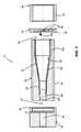
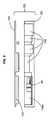
図1および図2は、例示的なステントをステント弁10の形式において示す。ステント弁10は、心臓のステント弁、例えば大動脈のステント弁であってもよい。ステント弁10は、身体における経カテーテル留置のために構成されて、例えば低侵襲性技術の使用を可能にしてもよい。ステント弁10は経カテーテル大動脈弁留置(「TAVI」)のために構成されてもよい。或る特定の形状のステント弁10が例として示されるが、この発明はいかなる特定のステント弁形状にも限定されないことが十分に理解される。例示的形状がここで用いられるのは、それによってこの発明の利点を強調することが可能であるからである。 1 and 2 show an exemplary stent in the form of a
ステント弁10は、(図1に示される)拡張された状態と、破線10′によって示された圧縮した状態との間で、変形可能であってもよい。拡張された状態は、おおよそ、留置後のステント弁の作用状態に対応してもよい。ステント弁10は、留置で、拡張された状態を完全には達成しない場合があり、生来の解剖学的構造における摩擦嵌めのための外方向の弾性付勢を維持するよう、サイズの不一致および/または僅かな圧縮に対して、許容差を見込む。圧縮した状態10′は、デリバリーカテーテル12によって収容されるべき、および/または解剖学的構造内の所望の留置部位への導入のための送給状態に対応してもよい。
ステント弁10は、拡張された状態に向かって弾性的に付勢され、好適な径方向圧縮力の適用により圧縮した状態10′に圧縮可能な、自己拡張型であってもよい。ステント弁10は、抑制されている間、その圧縮した状態にとどまる。抑制が除去されると、ステント弁10は拡張された状態に向かって自己拡張する。代替的に、ステント弁10は、ステント弁10を圧縮した状態10′から拡張された状態に変形するために拡張力の適用を必要とする非自己拡張型であってもよい。 The
ステント弁10は、ステント構成要素14および弁構成要素16を含んでもよい。ステント構成要素14は、ステント弁を生来の解剖学的構造に係留するための係留機能、および/または弁構成要素16を支持するための支持機能を提供してもよい。ステント構成要素14は任意の好適な材料から形成されてもよい。ステント構成要素14は金属製であってもよい。例示的な材料は、形状記憶および/または超弾性合金(例えばニチノール)、ステンレス鋼またはコバルトクロム合金を含む。示された形式においては、ステント構成要素14は、自己拡張型であり、形状記憶/超弾性合金(例えばニチノール)である。しかしながら、ステント構成要素14は、実質的に非自己拡張型でもあり得る。
ステント構成要素14は、生来の解剖学的構造の所望の留置部位に関してステント弁10を係留および/または整列させるために所望される任意のプロファイルを有してもよい。いくつかの実施例においては、ステント構成要素14は、略円筒形であるか、または1つ以上の略円筒形の部分もしくは略円筒形の面の上にある部分(例えば20cおよび22a)を含んでもよい。加えて、または代替的に、ステント構成要素14は、略非円筒形であるか、または1つ以上の略非円筒形の部分もしくは非円筒形の面の上にある部分(例えば20a、20bおよび24)を含んでもよい。加えて、または代替的に、ステント構成要素14は、1つ以上の係留突起および/または1つ以上の安定化部分を含んでもよい。 The
示された形式においては、ステント構成要素14は、例えば溝および/またはくびれ20cを間に規定する下位の冠部20aおよび上位の冠部20bによって規定された係留部分20を任意で含む。係留部分20は、第1の圧縮抵抗を有してもよく、セル状格子を含んでもよい。 In the form shown, the
ステント構成要素14は、例えば、複数(例えば3つ)の継ぎ目の支柱22aを含む弁支持部分22を任意で(さらに)含む。継ぎ目の支柱22aは、冠部20aおよび20bの少なくとも1つの末端より小さなピッチ円径上に配されてもよい。継ぎ目の支柱22aは、くびれに20c対応するピッチ円径上に配されてもよい。継ぎ目の支柱22aは、部分的に、軸方向に冠部20および22の少なくとも1つと重なり、そのそれぞれの冠部を越えて軸方向に延在してもよい。継ぎ目の支柱22aはフレーム状であってもよい。継ぎ目の支柱22aは、少なくとも継ぎ目の支柱に近接する弁周縁の領域において少なくともおおよそ弁の周縁輪郭を辿る形状を有してもよい。 The
ステント構成要素14は、例えば複数(例えば3つ)の羽根部またはアーチ24aによって規定された安定化部分または整列部分24を任意で(さらに)含む。アーチ24aは、継ぎ目の支柱22aの先端から延在して、丸天井のような構造をその上に規定してもよい。整列部分24は、係留部分20および/または弁支持機能22より大きな柔軟性を有してもよい。整列部分24は、係留部分20の第1の圧縮抵抗より小さい第2の圧縮抵抗を有してもよい。整列部分24は、係留部分20および/または弁支持部分22ほど(例えば径方向に)剛性でなくてもよい。 The
ステント構成要素14は、ステント構成要素14をデリバリーカテーテル12のステントレシーバ28に取付けるための取付け部分26を任意で(さらに)含む。示された実施例においては、ステントレシーバ28はステントホルダであってもよく、以下にそのように指称されるが、ステント弁10の少なくとも一部を受け、および/または収容するための他のタイプのレシーバが、所望のように用いられてもよい。取付け部分26は、ステントホルダ28の相補的な部分との締り嵌め(例えば食い込み嵌め)の形成のために、1つ以上の幾何学的な開口部または1つ以上の耳部もしくは他の突起を含んでもよい。取付け部分26は、ステント構成要素14の少なくとも1つの末端部またはその近くに配されてもよい。この実施例においては、取付け部分26は、下位の冠部20aの格子目の複数(例えば3つ)の延長部分によって規定される。
弁構成要素16は、任意の好適な天然および/または合成の材料であってもよい。例えば、弁構成要素16は、豚および/もしくは牛の心膜ならびに/または採取された天然の弁材料を含んでもよい。弁構成要素16は、閉位置に繋ぎ合わされるかまたは折り畳まれて、それを通る1つの方向においては流れを妨害し、開位置に撓んで離れて、反対方向においては流れを可能にする、複数の弁尖を含んでもよい。弁構成要素16は、弁支持部分22において、および/または少なくとも部分的に係留部分20内に収容されてもよい。ステント弁10(例えば弁構成要素16)は、ステント構成要素14のそれぞれの内側表面部分または外側表面部分を少なくとも部分的に覆う内側スカート部および/または外側スカート部をさらに含んでもよい。例えば、スカート部は、係留部分20の少なくとも一部および/または弁支持部分22の少なくとも一部を覆ってもよい。 The
さらに図1を参照して、デリバリーカテーテル12は、例としてのみ、ステント弁10の収容のために、デリバリーカテーテル12の封じ込め領域で少なくとも1つのシース30を含んでもよい。少なくとも1つのシース30は、ステント弁10を拡張に抗して抑制するためにステント弁10の少なくとも一部をその圧縮した状態10′において覆うために構成されてもよい。少なくとも1つのシース30は、デリバリーカテーテル12のハンドル端32での制御による作動に応答して、選択的にステント弁10のそれぞれの領域を覆うかまたは露出するように、カテーテルの軸に沿って並進可能である。ステントホルダ28は、シース30の並進中に軸方向に変位するステント弁10のどのような傾向も防止もしくは少なくとも低減するか、および/またはステント弁10の僅かな部分のみがシース30によって覆われるときにシース30から免れて跳躍するステント弁10のどのような傾向も防止もしくは少なくとも低減してもよい。ステントホルダ28は、例えば、ガイドワイヤを受けるために、中央チューブ36(または複数のチューブの組立体)上に担持されてもよい。装填先端34は、チューブ36の最遠位端部において取り外し可能に取付けられてもよい。デリバリーカテーテル12の他の設計は、例えば、シース30および/またはステントホルダ28なしに用いられてもよい。例示のデリバリーカテーテル12がここで用いられるのは、それによってこの発明の利点を強調することが可能であるからである。 Still referring to FIG. 1, the
その拡張された状態におけるステント弁10の最大外径は、約25mmから約35mmであってもよい。対照的に、デリバリーカテーテルのためにその圧縮した状態10′におけるステント弁の最大外径は、有意により小さく、例えば約10mm以下であってもよい。ステント弁を圧縮するように適用されるよう必要な径方向力は、相当なものであってもよく、例えば、少なくとも50N、少なくとも75N、または少なくとも100Nであってもよい。いくつかの実施例においては、径方向力は約100Nと120Nとの間にある。 The maximum outer diameter of the
図3〜図7を参照して、装置40は、ステント弁10をその圧縮した状態10′に圧縮するために示される。装置40も、圧縮プロセスの一部としてデリバリーカテーテル12にステント弁10を装填することを容易にするように構成される。 With reference to FIGS. 3-7,
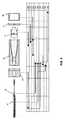
装置40は:中空のチャネル(または中空のチャネル部材もしくは中空のチャネル本体)42;移動部44;ドライバ46;装填チューブ(またはチャネル延長部分)48の構成要素の1つまたは2つ以上の任意の組合せも含んでもよい。構成要素42〜48のいくつかまたはすべては、互いから解体可能であってもよく、装置40の使用中に組付けられてもよい。 The
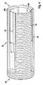
中空のチャネル42は、ステント弁10がチャネル42内を一方の端部の入口52から対向する端部の出口54へと長手方向に前進するのに応答してステント弁10を漸進的に圧縮するために形状化された内部表面50を有してもよい。内部表面50は、圧縮中にステント弁10の円形の形状を維持するために、断面において略円形であってもよい。内部表面50は、例えば、出口54に向かう方向においてチャネル42の長手方向軸に沿って漸進的に低減する直径を有する(例えば先細になる)1つ以上の非円筒形部分50bおよび50dを含んでもよい。そのような形状は、じょうご形と呼ばれてもよい。じょうごは、プロファイルにおいて、真っすぐな側部を有してもよく、または凹状もしくは凸状であってもよい。内部表面50は、さらに、1つ以上の略円筒形の部分50aおよび50cを含んでもよい。内部表面50は、例えば疎水性のシリコーンに基づいたコーティングで、表面50とステント弁10との間の摩擦を低減するようにコーティングされてもよい。 The
示された実施例においては、略円筒形の部分50aはチャネル42の入口52に近接して設けられる。円筒形部分50aは、実質的な圧縮なしに(および自己拡張型ステント弁の場合においては、ステント弁が跳ね返って入口52から出る傾向なしに)チャネル42内へのステント弁10の初期挿入を容易にしてもよい。加えて、または代替的に、略非円筒形の部分50d(例えばじょうご形状の)は、チャネル42の出口54に近接して設けられてもよい。非円筒形の部分50dは、ステント弁10が出口54に現れるときにステント弁10の端部で先細になる(例えば円錐形にテーパした)形状を促進することにより、装填中におけるステント弁10とデリバリーカテーテル12のステントホルダ28との係合を容易にしてもよい。 In the illustrated embodiment, the generally
チャネル42の出口54を、任意で、デリバリーカテーテル12のシース30の先端を受けるための環状のステップソケット54aとともに形成して、シース30内への装填を容易にしてもよい。ソケット54aは、そこで受けられるシース30の(例えば遠位の)端部の外径と実質的に一致する内径を有してもよい。 The
チャネル42の壁は、少なくとも径方向において、略定置状態であるかまたは固定されてもよい。ステント弁10が内部表面50に抗して耐えて、それに沿って、および/またはそれを通って前進するために圧縮するように強要されるように、ステント弁10の圧縮はチャネル42内においてステント弁10を前進させることによって達成される。 The walls of the
移動部44は、ステント弁10をチャネル42内において前進させるために、チャネル42内においてステント弁10にチャネル42の外部で生成された長手方向の駆動力をかけるために構成されてもよい。移動部44は、ステント弁10をチャネル42内において前進させるために、チャネル42の径方向に外側からステント弁10に長手方向の駆動力を適用するために構成されてもよい。移動部44は、チャネル42の壁においてそれぞれのスロット58において摺動し、チャネル42の外側からスロット58を通ってチャネル42の内部に突出する1つ以上の部分(例えば枝部)56を含んでもよい。(枝)部分56は、移動部44が長手方向に並進するよう駆動されるとステント弁10を前進させるためにステント弁10の部分を係合するために構成される。 The moving
そのような移動部44を用いて駆動力を適用することにより、駆動力がステントの対向する端部の中間の1つ以上の位置でステント弁に適用されることを可能にしてもよい。これによって、「押す」力が、軸方向圧縮荷重によるステントの部分の座屈の危険性がより少ない状態でかけられることができてもよい。加えて、または代替的に、それは、力(「引く」力または「押す」力)が、ステントの末端部と干渉することも、取付け部分26に依存したり、またはそれを用いることもなく、かけられることを可能にしてもよい。 Applying a driving force using such a moving
代替的に、移動部44は、駆動力がステント弁10の末端部において適用されることを可能にしながら、(i)ステント弁より長い中空のチャネルを通る、および/または(ii)それ自体が圧縮されるステント弁の一部に押す力をかける、ステント弁を前進させる方法という問題を解決してもよい。 Alternatively, the moving
加えて、または代替的に、そのような移動部44を用いて駆動力をかけることは、ステントが比較的堅固であり、および/または損傷もしくは変形にそれほど脆弱でない、1つ以上の位置(径方向および/または長手方向)において駆動力がかけられることを可能にしてもよい。 In addition, or alternatively, applying a driving force using such a moving
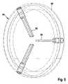
この例においては、駆動力は、継ぎ目の支柱22aにかけられるように意図される(図2および図7を参照)。駆動力「F」は、継ぎ目の支柱22aと各それぞれの柱22aに接続された整列アーチ24aとの間の接合点においてかけられてもよい。駆動力は、2つの近接するアーチ24a間の中空38(谷部または凹みとも呼ばれる)においてかけられてもよい。そのような技術を用いると、移動部44は、ステント弁10の(i)弁構成要素およびスカートがない位置で接触して、それに対する損傷を回避する、および/または(ii)圧縮中に密にパッキングされる係留部分20の格子構造がない位置でステント弁10と接触することが可能である。継ぎ目の支柱22aは、例えば安定化部分24より強い、駆動力を受けるための堅固な支持を与えてもよい。 In this example, the driving force is intended to be applied to the
(枝)部分56は、ステント弁10の係合のために所望される任意の好適な形状および構成も有してもよい。示された形式においては、各枝部分56は、略矩形であり、および/または断面形状において略平面である。枝部分56はブレード形状を有してもよい。断面形状は、ステント弁10と接触する相対的に薄い、および/または平坦な表面を与えてもよい。断面形状は、ステント弁10と接触する第1の寸法を規定してもよく、それは、第1の寸法を概ね横断する形状の寸法より小さくてもよい。 The (branch)
そのような形状は、枝部分56がステント弁10において空間を開くように割込むいかなる傾向も低減し、一方で、依然として、スロット58を通ってステント弁10に片持ち梁状に駆動力を伝達するために十分な曲げ強さを枝部分56に与えてもよい。 Such a shape reduces any tendency for the
図面において示された形式においては、枝部56は、略径方向(例えば、チャネル42の長手方向軸に垂直)において内方向に延在する。代替的に、各枝部分56は径方向に関して傾けられてもよい。傾斜の角度は、約5度以上、任意で約10度以上、任意で約15度以上、または任意で約20度以上であってもよい。加えて、または代替的に、傾斜の角度は、約30度以下、任意で約25度以下、任意で約20度以下、任意で約15度以下、任意で約10度以下であってもよい。(図3において矢印56aによって示されるように、枝部分56の内側先端が出口54に向かって傾斜するように、)移動部44がチャネル42上に取付けられるときに、枝部分56はチャネル42の出口54に向かう方向に傾けられてもよい。そのような構成は、圧縮中にステント弁が内方向に座屈する傾向を防止または少なくとも低減してもよい。代りに、その傾斜は、ステント弁を表面50に向かって適度に外方向に付勢し、表面50の存在は外方向の座屈を妨害する。他の実施例においては、異なる傾斜の角度および/または異なる傾斜の方向が用いられてもよい。さらに他の実施例においては、枝部56は、実質的に径方向において内方向に延在してもよい。 In the form shown in the drawings, the
示された形式においては、枝部分56の径方向に内側の先端または端部は自由であり、クリアランスをその間に規定する。ステント弁10が圧縮プロセスの一部としてデリバリーカテーテル12に装填されるなか、クリアランスは、デリバリーカテーテル12の遠位部分が収容されることを可能にする。他の形式においては、枝部分56の内側端部はともに結合されてもよい。 In the form shown, the radially inner tip or end of the
移動部44は、任意で、さらに、枝部分56を担持する、および/または枝部分56がそれから延在するリング60を含んでもよい。リング60はチャネル42の外側のまわりに嵌まり、チャネルの長さの少なくとも一部に沿って長手方向に摺動可能(例えば、少なくともスロット58の範囲に対応する部分に沿って摺動可能)であってもよい。スロット58は、入口においてステント弁10を導入するために移動部がチャネル42から係合解除されることを可能にするように、チャネル42の少なくとも一方の端部(例えば入口52)において開いていてもよい。 The moving
チャネル42は、(好ましい実施例において示されるように)スロット58が形成された実質的に単一の部材として形成されてもよい。代替的に、チャネル42は、まとめてチャネル形式を規定するようにともに組付け可能である複数の構成要素部品を含んでもよい。 The
いくつかの実施例においては、移動部44は、手で直接駆動されてもよいが、好ましい実施例においては、ドライバ46によって、移動部44のための駆動力を生成し(例えば均質に)かけるための付加的な便宜および制御を与えてもよい。 In some embodiments, the moving
ドライバ46は、チャネル42に関して可動であり、ドライバ46に適用される相対的な運動に応答して駆動力を生成するためにチャネル42に結合されてもよい(または結合可能であってもよい)。ドライバ46はチャネル42の外部にあってもよい。例えば、ドライバ46は、手で、または好適なツールを用いることで回転される回転式部材62を含んでもよい。回転式部材62はチャネル42の長手方向軸のまわりを回転可能であってもよい。回転式部材62は、回転式部材62の回転に応答して長手方向の変位を生成するためにねじ筋64および/またはヘリカルガイドによってチャネル42に結合されてもよい(または結合可能であってもよい)。ドライバ46(例えば回転式部材)は、直接的または間接的に移動部44に抗して(例えばリングに抗して)耐え、回転式部材62が回転すると、駆動力をそれにかける。(枝)部分56は、ステント弁10に駆動力を伝達して、ステント弁10をチャネル42内において前進させる。 The
示された形式においては、チャネル42は、回転式部材62のためのねじ筋64を担持する略円筒形の外部部分を有する。回転式部材62は、ねじを緩められて、例えばチャネル42の入口52において、ねじ筋64から外され解体されてもよい。そのようにねじを緩めること/解体は、チャネル42の入口内へのステント弁の挿入のための移動部の除去、およびその後の移動部44と回転式部材62との再嵌め合いを可能にする。 In the form shown, the
装填チューブ(またはチャネル延長部分)48は、設けられた場合には、穴66を含んでもよい。穴66は、直径において、デリバリーカテーテルのシース30の外部直径、および/またはソケット54aの直径に対応してもよい。示された形式においては、装填チューブ48は、穴66がチャネル出口54と実質的に整列される状態で延長部分48をチャネル42に取り外し可能に取付けるために固定部70を担持する唇状部68をさらに含む。固定部70は、例えばチャネル42の出口端部において、チャネル42のねじ筋64とねじ筋係合するための雌ねじねじ筋であってもよい。他の実施例においては、異なる固定部70が、装填チューブ48をチャネル42に取り外し可能に取付けるために用いられてもよい。さらに他の実施例においては、固定部は用いられなくてもよく、その代りに、装填チューブ48が、所望されたときに、手またはなんらかの他の外部のホルダによって適所に保持されてもよい。さらに他の実施例においては、装填チューブは、チャネル42の出口内に少なくとも部分的に挿入可能であるように寸法決めされてもよい。 If provided, the loading tube (or channel extension) 48 may include a hole 66. The hole 66 may correspond in diameter to the outer diameter of the
装填チューブ48は、設けられた場合、デリバリーカテーテル12とチャネル42との間の調整を単純化してもよい。装填チューブ48は、シース30を補強し、および/またはシースでステント弁10の少なくとも一部を捕捉する前にステント弁のその部分の装填チューブ48内への圧縮を可能にしてもよい。任意で、装填チューブ48はシース30上で摺動させられてもよい。装填チューブ48は、取付け部分26とステントホルダ28との間の装填係合(loading engagement)を容易にするために後ろに(チャネル42から遠ざかるように)摺動させられてもよい。その後、装填チューブを、前方に(チャネル42に向かって)摺動させて、シース30を補強し、および/またはステント弁10の漸進的な圧縮を集めるために連続的にシース30を調整する必要なしにステント弁10の延長部分48内への圧縮を可能してもよい。 When provided, the
上記の構成要素は、金属および/またはプラスチックおよび/またはセラミックスを含む、任意の好適な材料から形成されてもよい。 The above components may be formed from any suitable material, including metals and / or plastics and / or ceramics.
単に例として、チャネル42、ドライバ46および装填チューブ48は、プラスチック製であってもよく;および/または移動部44のリング60は金属であってもよく;および/または移動部44の枝部56は(例えばステント構成要素14との金属−金属接触を回避するように)プラスチック製であってもよい。他の形式においては、枝部56は、任意でコーティングされるかまたはプラスチックのカバーを担持している、金属またはセラミックスであり得る。代替的に、移動部44のリング60および枝部56は、例えば一体的にともに成型されたプラスチックであり得る。 By way of example only,
装填チューブ48および/またはチャネル42は、任意で透明または半透明で、オペレータが圧縮中にステント弁10の状態を見てデリバリーカテーテル12の装填および操作を補助することを可能にしてもよい。 The
例示的圧縮および/または装填プロセスが、ここで、図6に関して例示の態様でのみ記載され、構成要素の移動の相対的な方向は矢印のシーケンスで示される場合がある。 An exemplary compression and / or loading process will now be described in an exemplary manner only with respect to FIG. 6, where the relative directions of component movement may be indicated by a sequence of arrows.
ステップ100で、装填チューブ48は、設けられる場合には、チャネル42から分離される一方で、シース30上で摺動されてもよい。装填チューブ48がステントホルダ28を覆わないように、装填チューブ48はハンドル端(32)に向かって後方に摺動されてもよい。シース30もステントホルダ28を露出するように並進されてもよい。 At
さらにステップ100において、ステント弁10をチャネル42に挿入する前に、ドライバ46を回して外し、チャネル42から分離してもよい。移動部44を摺動させて、入口52においてスロット58の開いた端部から外してもよい。その後、ステント弁10は入口52内へと手で挿入されてもよい。ステント弁10は、取付け部分26を含む端部を最初に挿入されてもよい。この例においては、最初に挿入される端部は、係留部分20および/またはその下位の冠部20aを含む。移動部によって駆動力がかけられることになっているステント弁10の部分がスロット58と実質的に(または少なくともおおよそ)位置合わせされた状態で整列されるように、ステント弁10は回転式に方向づけられる。この例においては、これらの部分は継ぎ目の支柱22aに対応する。入口52における略円筒形の内部表面部分50aは、ステント弁10が、初めに実質的な圧縮なしに、相対的に容易に挿入されることを可能にする。 Further, in
ステップ102で、移動部44を入口52において再置して、リング60がチャネル42の外側に嵌まり、 枝部56がスロット58において受けられ、継ぎ目の支柱22aの先端を係合する(図7に示される)ようにしてもよい。 In step 102, the moving
ステップ104で、ドライバ46を入口52で移動部44のリング60上に置き、回転させて、ねじ筋によってねじ筋64を係合し、ステント弁10および移動部44をチャネル42に対して保持してもよい。 At step 104, the
その後(依然としてステップ104において)、チャネル42に対するドライバ46の継続的な回転は、移動部44を介してステント弁10にかけられる長手方向の駆動力を生成して、ステント弁10を出口54に向かって前進させる。ステント弁10が前進するにつれて、内部表面50の非円筒形の部分50bおよび50dとの接触は、ステント弁10を圧縮した状態に向かって漸進的に圧縮する。ステント弁10が出口54に接近するにつれて、取付け部分26が出口端部54において最初に出現してもよい。 Thereafter (still in step 104), continued rotation of the
ステップ106で、(以下に説明されるように、既に適所にない場合には)デリバリーカテーテルの遠位端部を、ステントホルダ28が露出した取付け部分26を係合し、および/またはそれと噛み合うまで、出口端部54内に導入してもよい。露出した取付け部分26がチャネルの出口端部54から突出するのを見ることができることは、取付け部分26のステントホルダ28との係合の作業を容易にする。出口54において内部表面50の非円筒形の部分50dを設けることは、出口54から突出する取付け部分26が先細になる形状を採用することを促し、ステントホルダ28との係合を容易にすることも促す。ある場合には、デリバリーカテーテルの遠位端部を、より早い段階において出口端部54内に導入して、それが既に適所において取付け部分26を受ける準備ができているようにしてもよく、または取付け部分26が一旦出口端部54に到着し始めると、それから現れる前に、導入してもよい。 In
ステップ108で、ステントホルダ28に取付けられた取付け部分26を覆うためにシース30を遠位に並進させ、それによってステント弁10の端部を捕捉してもよい。 At
その後、圧縮および/または装填プロセスのさらなるステップは、装填チューブ48を用いるかどうかに依存してもよい。装填チューブ48を用いない場合、そのプロセスはドライバ46の段階状の回転によって漸増的に進行して(ステップ112)、ステント弁10を短い距離だけ前進させ、その度毎に、出口54に向かってシース30の対応する(遠位)並進が後に続いて(ステップ114)、出口において新しく露出したステント弁の部分を漸進的に捕捉してもよい。その度毎に、シース30をソケット54a内において接触するまで並進させてもよい。 Thereafter, further steps of the compression and / or loading process may depend on whether or not the
代替的に、装填チューブ48を用いる場合、ステップ110で、装填チューブ48をシースに沿って摺動させてチャネル42の出口端部54と接触するようしてもよい。装填チューブ48を、(例えば固定部70を用いて)チャネル42に取付けても、または手で適所に保持してもよい。装填チューブ48は、補強または封じ込めを与えて、ステント弁10がチャネル42の出口端部54においてさらに現れる際にさらにシース30を段階的に並進させるいかなる必要性も回避または低減してもよい。代りに、ステップ112で、ドライバ46を回転させて、さらにシース30を並進させることなくステント弁10を十分な圧縮に向かって前進させてもよい。シース30は、単に、ステントホルダ28に取付けられた取付け部分26を覆ったままであってもよい。シース30は出口54から変位してもよいが、その間中ずっと、装填チューブ48内に封じ込められたままである。装填チューブ48は、圧縮したステント弁10を一時的に円筒形または円筒形に近い圧縮した状態に封じ込めてもよい。一旦、移動部44が出口54の近くでスロット58の端部において最終位置に達すると、ステップ114で、シース内において、装填チューブ48によって封じ込められたステント弁10の部分を捕捉するために、シース30をチャネル42の出口端部54に向かって再び並進させてもよい。ステント弁が装填チューブ48の穴66からシース30内へと通過するために必要とされるさらなる圧縮の量は、相対的に小さいものであり、装填チューブ48内におけるシース30の並進によって容易に達成されてもよいことが理解されるであろう。万一、補強が必要ならば、シース30を取り囲む装填チューブ48はシース30を補強してもよい。 Alternatively, if a
いずれの技術を用いても、ステント弁10は、係留部分20の少なくとも大部分(および任意で弁支持部分22の少なくとも一部)を圧縮しシース30内に装填する、実質的に圧縮した状態に到達する。ステント弁10の安定化部分24はチャネル42内にとどまってもよい。ステップ116で、装置40をデリバリーカテーテル12から遠位に摺動させることによって、装置40はデリバリーカテーテル12およびステント弁10から係合解除される。中空のチャネル24を先に出なかったかもしれないステント弁10の安定化部分24の少なくとも一部は、再拡張しがちかもしれず、なぜならば、その部分24はシース30によっては封じ込められないからである。しかしながら、安定化部分24は、径方向において相対的に可撓性があり、以下に説明されるように、後で、中空のチャネル42に対する必要性なしに、容易に圧縮することが可能である。 With either technique, the stent-
装填プロセスの最終段階(これらは装置40と直接関係がないので、図6には示されない)は:
(i)デリバリーカテーテル12の装填先端34を除去し、留置先端によって置換すること;および
(ii)シース30をさらに遠位に並進させて安定化部分24を圧縮すること、の1つ以上を含んでもよい。シース30を並進させて送給先端と接触させて、留置のための使用に対する準備ができているデリバリーカテーテル12の遠位領域を閉じてもよい。The final stages of the loading process (these are not directly related to the
One or more of: (i) removing the
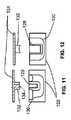
図8〜図14は、デリバリーカテーテル12を保管、輸送、およびそれが用いられる現場に供給してもよい、例示的梱包120を示す。図14にデリバリーカテーテル12の位置を示す。梱包120は、任意で、ステント弁10の圧縮および/または装填のために(図9、図10、図13および図14において)装置40も含む。装置40は、上記の実施例の特徴の任意のものであるか、またはそれを含んでもよい。 FIGS. 8-14 illustrate an
梱包120は、概して、基部122と、基部122を覆って梱包120閉じるためのカバー(例えば蓋)124とを含む。基部122はデリバリーカテーテル12を少なくとも部分的に受けるための谷部126を含む。示された実施例においては、谷部126は、デリバリーカテーテル12の実質的に全体を収容することが可能であるように寸法決めされる。 The
この実施例の特徴は、谷部126は、概ね液密であり、ステント弁10および/またはデリバリーカテーテル12の封じ込め領域12aが、ステント弁10をデリバリーカテーテル12に関して圧縮および/または装填するよう動作中に浸漬される液体を保持することに対して使用可能である、ということであってもよい。任意で、さらなる特徴は、同じ谷部126を用いて、デリバリーカテーテル12を、(i)デリバリーカテーテル12を初めに供給する梱包120における保管位置、および(ii)ステント弁10をデリバリーカテーテル12に装填するための装填位置に保持することであってもよい。任意で、保管位置および装填位置は実質的に互いと同じであってもよい。位置の少なくとも一方(または適切には両方の位置)において、デリバリーカテーテル12は、基部の面と実質的に平行であってもよく、および/またはステント弁を装填するための使用の際に実質的に水平であってもよい。デリバリーカテーテル12を基部の面と実質的に平行に配置することは、梱包の高さを望ましいように小さく保持することを可能にすることが可能である。デリバリーカテーテル12を、基部の面と実質的に平行に、および/またはステント弁の装填中の使用の際に実質的に水平に配置することは、(i)谷部を充填するために必要とされる液体の量が望ましいように小さく保持されること、および/または(ii)装填動作中においてデリバリーカテーテル内に避けがたく捕捉されるかもしれない空気の量を低減することを可能にする。捕捉された空気は患者の体内へのカテーテルの挿入に先立って除去するべきであり、充填中において捕捉されるであろう空気の量を低減することは、そのような後の「脱気」ステップの負担を緩和し得る。 A feature of this embodiment is that the
谷部126は一様な深さを有してもよく、またはそれはその長さに沿って変動する深さを有してもよい。ステント弁10を圧縮および/または装填する、またはデリバリーカテーテル12の封じ込め領域12aを収容する、少なくとも領域126aにおいては、谷部126はステント弁10および/または装填装置40の横方向寸法より大きな深さを有する。例えば、領域126aにおける深さは:少なくとも1cm;少なくとも2cm;少なくとも3cm;少なくとも4cm;少なくとも5cm;少なくとも6cm;少なくとも7cm;少なくとも8cm;少なくとも9cm;少なくとも10cm;少なくとも11cm;少なくとも12cm;少なくとも13cm;少なくとも14cm;少なくとも15cmであってもよい。 The
谷部126は一様な幅を有してもよく、またはそれはその長さに沿って変動する幅を有してもよい。 The
いくつかの実施例においては、谷部126は、デリバリーカテーテル12の或る形式の部分にフィットしてカテーテルを実質的な移動に抗して抱えるように支えるソケットをともに規定する1つ以上の第1の表面部分128を含む。加えて、または代替的に、谷部126は、カテーテルを操作および/またはシースを並進させるように手動で把持またはアクセスされるよう意図される、デリバリーカテーテルの部分12bに近接するクリアランス130aをともに規定する1つ以上の第2の表面部分130を含む。加えて、または代替的に、谷部126は、領域126aのためのクリアランスを規定する1つ以上の表面部分130を含む。いくつかの実施例においては、谷部126は、1つ以上の第1の表面部分128および1つ以上の第2の表面部分130を含み、デリバリーカテーテル12が第1の表面部分128によって規定された位置にある一方で、第2の表面部分130は手のアクセスがシースを操作することを許す。 In some embodiments, the
谷部126の基部は(任意で丸くされた角を伴って)略平坦であってもよく、および/または少なくとも谷部126の基部の部分は、デリバリーカテーテルおよび/または装填装置を、下から、抱えるように、またはカップ形状で支えるように、形状化されてもよい。 The base of the
谷部126の液体容量は、設計によって選択されてもよい。いくつかの実施例においては、液体容量は、(任意で、デリバリーカテーテル12および/または装填装置40が谷部126内において適所にある状態で)谷部126のための液体の量が:4リットル以下;3.5リットル以下;3.25リットル以下;3リットル以下;少なくとも1リットル;少なくとも2リットルから選択される1つ以上であってもよい。例えば、液体の量は、デリバリーカテーテル12および装填装置40の両方を谷部126内に置くときに測定してもよい。 The liquid capacity of the
カバー124は、任意で、カバー124から懸架し、谷部126と噛み合い、ならびに/または(i)デリバリーカテーテル12および/もしくは(ii)装填装置40と係合して、デリバリーカテーテル/装填装置を谷部内において捕捉状態に保持する1つ以上の尾根のような1つ以上の突起132を含む。突起132は、デリバリーカテーテル/装填装置の表面をカップ形状で支えるように構成される、凹形状のようなプロファイル134を有してもよい。 The
装填装置40は、任意で、谷部126とは異なる区画内に収納されてもよく、またはそのために取っておかれた谷部126の領域136に収納されてもよい。上に説明されるように、装填装置40はカバー124(またはカバーの突起132)によって適所に抑制されてもよい。 The
基部122は、付属物を収納するための、谷部126とは異なる1つ以上の区画をさらに含んでもよい。 The base 122 may further include one or more compartments for storing accessories that are different from the
基部122および/またはカバー124は、任意の好適な材料、例えばプラスチックであってもよい。任意の好適な技術、例えばブロー成型または注入成形によって、基部122および/またはカバー124を形成してもよい。
梱包120を用いるための例示的なステップは:
(a)デリバリーカテーテル12および/または装填装置を収納している梱包120を、閉じられた形式で、与えること;
(b)梱包120を開く(例えばカバー124を除去する)こと;
(c)液体を谷部126内に導入すること;および
(d)少なくともステント弁および/またはデリバリーカテーテル12の封じ込め領域12aを谷部において液体に浸漬しながらステント弁を封じ込め領域12a内に装填すること、の1つ以上を任意の順序で含んでもよい。例えば、装置40はデリバリーカテーテル12の先端に配置され、谷部126の領域126a内において操作されてもよい。Exemplary steps for using the
(A) providing the
(B) opening the package 120 (eg, removing the cover 124);
(C) introducing liquid into the
液体は例えば塩水であってもよい。液体は体温より冷たくてもよい。例えば、液体はおおよそ室温であってもよい。 The liquid may be salt water, for example. The liquid may be cooler than body temperature. For example, the liquid may be approximately room temperature.
ステップ(d)は、デリバリーカテーテルl2が実質的に水平の状態で実行されてもよい。 Step (d) may be performed with the
この方法は、装填動作の後にデリバリーカテーテル12から捕捉された空気を除去するステップ(例えば「脱気」ステップ)をさらに含んでもよい。上に説明されたように、デリバリーカテーテルl2が実質的に水平の状態でステップ(d)を実行することは、装填動作中に捕捉された空気の量を低減してもよい。 The method may further include removing air trapped from the
ステップ(d)は、図面の図6に関して上に記載されたステップを含んでもよい。
前述の記載は、この発明の好ましい実施例の単なる例示であり、保護範囲を限定しない。この発明の範囲内において、多くの等価物、修正物および改善物を用いてもよい。Step (d) may include the steps described above with respect to FIG. 6 of the drawings.
The foregoing descriptions are merely illustrative of preferred embodiments of the present invention and do not limit the scope of protection. Many equivalents, modifications and improvements may be used within the scope of the present invention.
Claims (21)
Translated fromJapanese中におけるステントの長手方向の前進に応答して前記ステント弁を漸進的に圧縮するために形状化された内部表面(50)を有する中空のチャネル(42)を含み、前記中空のチャネルは、その壁を通して少なくとも1つのスロット(58)を含み;前記装置はさらに、
前記中空のチャネルの周方向周囲の外側に嵌まる部分(60)と、前記スロットにおいて摺動可能であり、前記スロットを通って突出して、前記ステント弁を前記中空のチャネル内において係合するための部分(56)とを含み、前記ステント弁に前記中空のチャネルの径方向に外側から長手方向の駆動力をかけるための移動部(44)を含む、装置(40)。An apparatus (40) for compressing a transcatheter heart stent valve (10) comprising:
A hollow channel (42) having an inner surface (50) shaped to progressively compress the stent-valve in response to a longitudinal advancement of the stent therein, the hollow channel comprising: Including at least one slot (58) through the wall;
A portion (60) that fits around the circumferential circumference of the hollow channel and is slidable in the slot and protrudes through the slot to engage the stent-valve in the hollow channel. And a moving portion (44) for applying a longitudinal driving force to the stent-valve from the outside in theradial direction of the hollow channel.
(i)前記第1および第2の端部の両方から、少なくとも5mm、好ましくは少なくとも10mm、間隔を置かれた位置;および/または、
(ii)前記第1および第2の端部の両方から、前記ステント弁の最大長さの少なくとも10%、好ましくは少なくとも15%、間隔を置かれた位置から選択される少なくとも1つである、請求項14に記載の装置。The at least one position is
(I) at least 5 mm, preferably at least 10 mm, spaced from both the first and second ends; and / or
(Ii) at least one selected from spaced apart positions at least 10%, preferably at least 15% of the maximum length of the stent-valve from both the first and second ends; The apparatus according to claim14 .
(i)少なくとも1つの略円筒形の表面(50a;50c)、および少なくとも1つの略非円筒形の表面(50b;50d);ならびに
(ii)複数の別個の略非円筒形の表面(50b、50d)、から選択される少なくとも1つを含む、請求項1から15のいずれか1つに記載の装置(40)。Before Symbol inside surface:
(I) at least one generally cylindrical surface (50a; 50c) and at least one generally non-cylindrical surface (50b; 50d); and (ii) a plurality of separate generally non-cylindrical surfaces (50b,The device (40) accordingto any one of the precedingclaims , comprising at least one selected from 50d).
使用に先立って前記デリバリーカテーテルを収納するための梱包を含み、前記梱包は、液密の谷部を有する基部を含み、前記谷部は、前記カテーテルの前記封じ込め領域が前記装填動作中において浸漬されてもよい液体を保持するように、使用に対して好適な深さを有する、請求項1から16のいずれか1つに記載の装置。A delivery catheter for delivering a stent valve to an indwelling site in the body, wherein the delivery catheter compresses the stent valve as a result of a loading operation for compressing and loading the stent valve with respect to the delivery catheter; Having at least one translatable sheath in the containment region for receiving;
Including a package for containing the delivery catheter prior to use, the package including a base having a liquid-tight trough, wherein the trough is immersed in the containment region of the catheter during the loading operation.17. A device accordingto any one of the preceding claims , having a depth suitable for use so as to hold liquid that may be present.
(a)入口(52)および出口(54)を有する中空のチャネル(42)を設けるステップを含み、前記中空のチャネルは、さらに、前記チャネル内におけるステント弁の長手方向の前進に応答して前記ステント弁を漸進的に圧縮するために形状化された内部表面(50)を有し、前記方法はさらに、(A) providing a hollow channel (42) having an inlet (52) and an outlet (54), wherein the hollow channel is further responsive to longitudinal advancement of the stent-valve within the channel. Having an internal surface (50) shaped to progressively compress the stent-valve, said method further comprising:
(b)ステント弁(10)を前記チャネルの前記入口に挿入するステップと、(B) inserting a stent-valve (10) into the inlet of the channel;
(c)前記チャネルの径方向に外側から長手方向の駆動力をかけて、前記ステント弁を前記チャネル内において前記出口に向かって前進させるステップとを含む、方法。(C) applying a longitudinal driving force from the outside in the radial direction of the channel to advance the stent valve in the channel toward the outlet.
Applications Claiming Priority (3)
| Application Number | Priority Date | Filing Date | Title |
|---|---|---|---|
| EP11164926AEP2520251A1 (en) | 2011-05-05 | 2011-05-05 | Method and Apparatus for Compressing Stent-Valves |
| EP11164926.5 | 2011-05-05 | ||
| PCT/EP2012/058085WO2012150290A1 (en) | 2011-05-05 | 2012-05-03 | Method and apparatus for compressing/loading stent-valves |
Publications (3)
| Publication Number | Publication Date |
|---|---|
| JP2014518697A JP2014518697A (en) | 2014-08-07 |
| JP2014518697A5 JP2014518697A5 (en) | 2015-06-18 |
| JP6017540B2true JP6017540B2 (en) | 2016-11-02 |
Family
ID=44583856
Family Applications (1)
| Application Number | Title | Priority Date | Filing Date |
|---|---|---|---|
| JP2014508797AActiveJP6017540B2 (en) | 2011-05-05 | 2012-05-03 | Method and apparatus for compressing / loading a stent valve |
Country Status (9)
| Country | Link |
|---|---|
| US (3) | US10335270B2 (en) |
| EP (5) | EP2520251A1 (en) |
| JP (1) | JP6017540B2 (en) |
| CN (1) | CN103517689B (en) |
| AU (1) | AU2012251646B2 (en) |
| BR (1) | BR112013028002B1 (en) |
| CA (2) | CA3061117C (en) |
| ES (1) | ES2593056T3 (en) |
| WO (1) | WO2012150290A1 (en) |
Families Citing this family (117)
| Publication number | Priority date | Publication date | Assignee | Title |
|---|---|---|---|---|
| US9532868B2 (en)* | 2007-09-28 | 2017-01-03 | St. Jude Medical, Inc. | Collapsible-expandable prosthetic heart valves with structures for clamping native tissue |
| US20090105813A1 (en)* | 2007-10-17 | 2009-04-23 | Sean Chambers | Implantable valve device |
| US20090276040A1 (en) | 2008-05-01 | 2009-11-05 | Edwards Lifesciences Corporation | Device and method for replacing mitral valve |
| CA2961053C (en) | 2009-04-15 | 2019-04-30 | Edwards Lifesciences Cardiaq Llc | Vascular implant and delivery system |
| NZ596179A (en) | 2009-04-29 | 2014-05-30 | Cleveland Clinic Foundation | Apparatus and method for replacing a diseased cardiac valve |
| EP2754463B1 (en) | 2009-05-15 | 2016-06-22 | Intersect ENT, Inc. | Expandable devices |
| US8652203B2 (en) | 2010-09-23 | 2014-02-18 | Cardiaq Valve Technologies, Inc. | Replacement heart valves, delivery devices and methods |
| US8449599B2 (en) | 2009-12-04 | 2013-05-28 | Edwards Lifesciences Corporation | Prosthetic valve for replacing mitral valve |
| US8579964B2 (en) | 2010-05-05 | 2013-11-12 | Neovasc Inc. | Transcatheter mitral valve prosthesis |
| AU2011300644B2 (en)* | 2010-09-10 | 2015-08-20 | Symetis Sa | Valve replacement devices and a system comprising the valve replacement device and a delivery device therefor |
| US9155619B2 (en)* | 2011-02-25 | 2015-10-13 | Edwards Lifesciences Corporation | Prosthetic heart valve delivery apparatus |
| US9308087B2 (en) | 2011-04-28 | 2016-04-12 | Neovasc Tiara Inc. | Sequentially deployed transcatheter mitral valve prosthesis |
| US9554897B2 (en) | 2011-04-28 | 2017-01-31 | Neovasc Tiara Inc. | Methods and apparatus for engaging a valve prosthesis with tissue |
| EP2520251A1 (en)* | 2011-05-05 | 2012-11-07 | Symetis SA | Method and Apparatus for Compressing Stent-Valves |
| CN104114127B (en) | 2011-12-09 | 2017-09-05 | 爱德华兹生命科学公司 | Prosthetic heart valve with improved commissural support |
| US8652145B2 (en) | 2011-12-14 | 2014-02-18 | Edwards Lifesciences Corporation | System and method for crimping a prosthetic valve |
| US9345573B2 (en) | 2012-05-30 | 2016-05-24 | Neovasc Tiara Inc. | Methods and apparatus for loading a prosthesis onto a delivery system |
| US9439763B2 (en) | 2013-02-04 | 2016-09-13 | Edwards Lifesciences Corporation | Prosthetic valve for replacing mitral valve |
| AU2014236729B2 (en)* | 2013-03-14 | 2018-11-22 | Intersect Ent, Inc. | Systems, devices, and method for treating a sinus condition |
| US20140277427A1 (en) | 2013-03-14 | 2014-09-18 | Cardiaq Valve Technologies, Inc. | Prosthesis for atraumatically grasping intralumenal tissue and methods of delivery |
| US9125763B2 (en) | 2013-03-15 | 2015-09-08 | Abbott Cardiovascular Systems Inc. | Stent crimping tool insert, system, and method |
| WO2014181188A2 (en)* | 2013-03-15 | 2014-11-13 | Valve Medical Ltd. | System and method for sealing percutaneous valve |
| US9572665B2 (en) | 2013-04-04 | 2017-02-21 | Neovasc Tiara Inc. | Methods and apparatus for delivering a prosthetic valve to a beating heart |
| US10188515B2 (en) | 2013-05-13 | 2019-01-29 | Medtronic Vascular Inc. | Devices and methods for crimping a medical device |
| EP4000560B1 (en) | 2013-09-16 | 2024-08-21 | Boston Scientific Medical Device Limited | A loading tube apparatus for compressing/loading stent-valves |
| CN106562840B (en)* | 2013-10-31 | 2018-06-22 | 上海微创心通医疗科技有限公司 | A kind of guiding lid and Load System being loaded into implant in transport system |
| CN104644298B (en)* | 2013-11-22 | 2019-06-11 | 斯波瑞申有限公司 | Direct valve loader |
| ES2711663T3 (en)* | 2014-03-18 | 2019-05-06 | Nvt Ag | Cardiac valve implant |
| US10195025B2 (en) | 2014-05-12 | 2019-02-05 | Edwards Lifesciences Corporation | Prosthetic heart valve |
| US9532870B2 (en) | 2014-06-06 | 2017-01-03 | Edwards Lifesciences Corporation | Prosthetic valve for replacing a mitral valve |
| EP3054893B1 (en) | 2014-09-24 | 2017-04-12 | Sorin Group Italia S.r.l. | A holder for heart valve prostheses, corresponding storage arrangement, delivery instrument and kit |
| KR20170066470A (en) | 2014-09-28 | 2017-06-14 | 카디오키네틱스 인크. | Apparatuses for treating cardiac dysfunction |
| US10531951B2 (en) | 2014-11-26 | 2020-01-14 | Edwards Lifesciences Corporation | Transcatheter prosthetic heart valve and delivery system |
| EP3028668B1 (en) | 2014-12-05 | 2024-10-30 | Nvt Ag | Prosthetic heart valve system and delivery system therefor |
| US10925611B2 (en) | 2015-01-20 | 2021-02-23 | Neurogami Medical, Inc. | Packaging for surgical implant |
| WO2016153918A1 (en) | 2015-03-20 | 2016-09-29 | Cardiokinetix, Inc. | Systems and methods for delivering an implantable device |
| US10610394B2 (en) | 2015-08-11 | 2020-04-07 | Mokita Medical Gmbh | Systems and methods for using perfluorocarbons to remove gases from medical devices |
| US10278847B2 (en) | 2015-08-11 | 2019-05-07 | Mokita Medical Gmbh I.Gr. | Systems and methods for removing air from medical devices |
| US11026788B2 (en)* | 2015-08-20 | 2021-06-08 | Edwards Lifesciences Corporation | Loader and retriever for transcatheter heart valve, and methods of crimping transcatheter heart valve |
| US10350047B2 (en) | 2015-09-02 | 2019-07-16 | Edwards Lifesciences Corporation | Method and system for packaging and preparing a prosthetic heart valve and associated delivery system |
| US11033387B2 (en) | 2015-11-23 | 2021-06-15 | Edwards Lifesciences Corporation | Methods for controlled heart valve delivery |
| US10357351B2 (en) | 2015-12-04 | 2019-07-23 | Edwards Lifesciences Corporation | Storage assembly for prosthetic valve |
| CA3007660A1 (en) | 2015-12-15 | 2017-06-22 | Neovasc Tiara Inc. | Transseptal delivery system |
| US10433952B2 (en) | 2016-01-29 | 2019-10-08 | Neovasc Tiara Inc. | Prosthetic valve for avoiding obstruction of outflow |
| US10245136B2 (en) | 2016-05-13 | 2019-04-02 | Boston Scientific Scimed Inc. | Containment vessel with implant sheathing guide |
| US10639147B2 (en)* | 2016-06-24 | 2020-05-05 | Edwards Lifesciences Corporation | System and method for crimping a prosthetic valve |
| US11324495B2 (en) | 2016-07-29 | 2022-05-10 | Cephea Valve Technologies, Inc. | Systems and methods for delivering an intravascular device to the mitral annulus |
| US10646689B2 (en) | 2016-07-29 | 2020-05-12 | Cephea Valve Technologies, Inc. | Mechanical interlock for catheters |
| US10661052B2 (en) | 2016-07-29 | 2020-05-26 | Cephea Valve Technologies, Inc. | Intravascular device delivery sheath |
| US10974027B2 (en) | 2016-07-29 | 2021-04-13 | Cephea Valve Technologies, Inc. | Combination steerable catheter and systems |
| US10933216B2 (en) | 2016-08-29 | 2021-03-02 | Cephea Valve Technologies, Inc. | Multilumen catheter |
| US11109967B2 (en)* | 2016-08-29 | 2021-09-07 | Cephea Valve Technologies, Inc. | Systems and methods for loading and deploying an intravascular device |
| US11045315B2 (en) | 2016-08-29 | 2021-06-29 | Cephea Valve Technologies, Inc. | Methods of steering and delivery of intravascular devices |
| US10874512B2 (en) | 2016-10-05 | 2020-12-29 | Cephea Valve Technologies, Inc. | System and methods for delivering and deploying an artificial heart valve within the mitral annulus |
| CA3042588A1 (en) | 2016-11-21 | 2018-05-24 | Neovasc Tiara Inc. | Methods and systems for rapid retraction of a transcatheter heart valve delivery system |
| US10653523B2 (en) | 2017-01-19 | 2020-05-19 | 4C Medical Technologies, Inc. | Systems, methods and devices for delivery systems, methods and devices for implanting prosthetic heart valves |
| US10561495B2 (en) | 2017-01-24 | 2020-02-18 | 4C Medical Technologies, Inc. | Systems, methods and devices for two-step delivery and implantation of prosthetic heart valve |
| US12029647B2 (en) | 2017-03-07 | 2024-07-09 | 4C Medical Technologies, Inc. | Systems, methods and devices for prosthetic heart valve with single valve leaflet |
| WO2018169683A1 (en)* | 2017-03-13 | 2018-09-20 | Boston Scientific Scimed, Inc. | Hemostasis valves and methods for making and using hemostasis valves |
| US10898330B2 (en) | 2017-03-28 | 2021-01-26 | Edwards Lifesciences Corporation | Positioning, deploying, and retrieving implantable devices |
| US12036113B2 (en) | 2017-06-14 | 2024-07-16 | 4C Medical Technologies, Inc. | Delivery of heart chamber prosthetic valve implant |
| EP3446731A1 (en)* | 2017-08-23 | 2019-02-27 | ECP Entwicklungsgesellschaft mbH | Device for compressing a compressible part of a catheter pump |
| CA3073834A1 (en) | 2017-08-25 | 2019-02-28 | Neovasc Tiara Inc. | Sequentially deployed transcatheter mitral valve prosthesis |
| US10575949B2 (en) | 2017-10-23 | 2020-03-03 | St. Jude Medical, Cardiology Division, Inc. | Folding patterns and loading funnel for improved transcatheter valve loading forces |
| CN117481869A (en) | 2018-01-25 | 2024-02-02 | 爱德华兹生命科学公司 | Delivery system for assisting in recapture and repositioning of replacement valves after deployment |
| CN108464877B (en)* | 2018-03-05 | 2020-11-06 | 金仕生物科技(常熟)有限公司 | Transcatheter heart valve preassembly system and preassembly method |
| WO2019195860A2 (en) | 2018-04-04 | 2019-10-10 | Vdyne, Llc | Devices and methods for anchoring transcatheter heart valve |
| CN112437648B (en) | 2018-05-23 | 2024-08-09 | 恪心有限责任公司 | Holder for a heart valve prosthesis, storage device for a heart valve prosthesis, and crimping kit and method |
| JP7170127B2 (en) | 2018-05-23 | 2022-11-11 | コーシム・ソチエタ・ア・レスポンサビリタ・リミタータ | Loading system and associated loading method for implantable prostheses |
| CN110664523B (en)* | 2018-07-03 | 2022-06-21 | 先健科技(深圳)有限公司 | Conveyor for delivering interventional medical devices |
| US11857441B2 (en) | 2018-09-04 | 2024-01-02 | 4C Medical Technologies, Inc. | Stent loading device |
| US11351028B2 (en)* | 2018-09-04 | 2022-06-07 | 4C Medical Technologies, Inc. | Stent loading device with fluid reservoir |
| CN109009593A (en)* | 2018-09-09 | 2018-12-18 | 上海医立泰生物科技有限公司 | A kind of bracket auxiliary gatherer and bracket introduction method |
| US10595994B1 (en) | 2018-09-20 | 2020-03-24 | Vdyne, Llc | Side-delivered transcatheter heart valve replacement |
| US11071627B2 (en) | 2018-10-18 | 2021-07-27 | Vdyne, Inc. | Orthogonally delivered transcatheter heart valve frame for valve in valve prosthesis |
| US11344413B2 (en) | 2018-09-20 | 2022-05-31 | Vdyne, Inc. | Transcatheter deliverable prosthetic heart valves and methods of delivery |
| US10321995B1 (en) | 2018-09-20 | 2019-06-18 | Vdyne, Llc | Orthogonally delivered transcatheter heart valve replacement |
| US12186187B2 (en) | 2018-09-20 | 2025-01-07 | Vdyne, Inc. | Transcatheter deliverable prosthetic heart valves and methods of delivery |
| US11278437B2 (en) | 2018-12-08 | 2022-03-22 | Vdyne, Inc. | Compression capable annular frames for side delivery of transcatheter heart valve replacement |
| US11109969B2 (en) | 2018-10-22 | 2021-09-07 | Vdyne, Inc. | Guidewire delivery of transcatheter heart valve |
| CN113271890B (en) | 2018-11-08 | 2024-08-30 | 内奥瓦斯克迪亚拉公司 | Ventricular deployment of transcatheter mitral valve prosthesis |
| US11724068B2 (en) | 2018-11-16 | 2023-08-15 | Cephea Valve Technologies, Inc. | Intravascular delivery system |
| US11241312B2 (en) | 2018-12-10 | 2022-02-08 | Boston Scientific Scimed, Inc. | Medical device delivery system including a resistance member |
| US11253359B2 (en) | 2018-12-20 | 2022-02-22 | Vdyne, Inc. | Proximal tab for side-delivered transcatheter heart valves and methods of delivery |
| WO2020146842A1 (en) | 2019-01-10 | 2020-07-16 | Vdyne, Llc | Anchor hook for side-delivery transcatheter heart valve prosthesis |
| CN111467080B (en)* | 2019-01-24 | 2024-12-06 | 上海微创心通医疗科技有限公司 | Implant loading tool, compression device and loading system |
| US11185409B2 (en) | 2019-01-26 | 2021-11-30 | Vdyne, Inc. | Collapsible inner flow control component for side-delivered transcatheter heart valve prosthesis |
| US11273032B2 (en) | 2019-01-26 | 2022-03-15 | Vdyne, Inc. | Collapsible inner flow control component for side-deliverable transcatheter heart valve prosthesis |
| WO2020181154A2 (en) | 2019-03-05 | 2020-09-10 | Vdyne, Inc. | Tricuspid regurgitation control devices for orthogonal transcatheter heart valve prosthesis |
| CA3132873A1 (en) | 2019-03-08 | 2020-09-17 | Neovasc Tiara Inc. | Retrievable prosthesis delivery system |
| US11076956B2 (en) | 2019-03-14 | 2021-08-03 | Vdyne, Inc. | Proximal, distal, and anterior anchoring tabs for side-delivered transcatheter mitral valve prosthesis |
| US11173027B2 (en) | 2019-03-14 | 2021-11-16 | Vdyne, Inc. | Side-deliverable transcatheter prosthetic valves and methods for delivering and anchoring the same |
| CA3135753C (en) | 2019-04-01 | 2023-10-24 | Neovasc Tiara Inc. | Controllably deployable prosthetic valve |
| US11491006B2 (en) | 2019-04-10 | 2022-11-08 | Neovasc Tiara Inc. | Prosthetic valve with natural blood flow |
| US11452628B2 (en) | 2019-04-15 | 2022-09-27 | 4C Medical Technologies, Inc. | Loading systems for collapsible prosthetic heart valve devices and methods thereof |
| ES2982566T3 (en) | 2019-04-23 | 2024-10-16 | Edwards Lifesciences Corp | Motorized implant delivery system |
| CA3138875A1 (en) | 2019-05-04 | 2020-11-12 | Vdyne, Inc. | Cinch device and method for deployment of a side-delivered prosthetic heart valve in a native annulus |
| US11779742B2 (en) | 2019-05-20 | 2023-10-10 | Neovasc Tiara Inc. | Introducer with hemostasis mechanism |
| CN110251273B (en)* | 2019-05-23 | 2022-09-13 | 沛嘉医疗科技(苏州)有限公司 | Transcatheter valve delivery preloading system device |
| JP7520897B2 (en) | 2019-06-20 | 2024-07-23 | ニオバスク ティアラ インコーポレイテッド | Thin prosthetic mitral valve |
| EP4480458A3 (en)* | 2019-08-20 | 2025-04-09 | Vdyne, Inc. | Delivery devices for side-deliverable transcatheter prosthetic valves |
| CN120531525A (en) | 2019-08-26 | 2025-08-26 | 维迪内股份有限公司 | Laterally deliverable transcatheter prosthetic valve and method for its delivery and anchoring |
| US11234813B2 (en) | 2020-01-17 | 2022-02-01 | Vdyne, Inc. | Ventricular stability elements for side-deliverable prosthetic heart valves and methods of delivery |
| US12133797B2 (en) | 2020-01-31 | 2024-11-05 | 4C Medical Technologies, Inc. | Prosthetic heart valve delivery system: paddle attachment feature |
| US11931253B2 (en) | 2020-01-31 | 2024-03-19 | 4C Medical Technologies, Inc. | Prosthetic heart valve delivery system: ball-slide attachment |
| US12053375B2 (en) | 2020-03-05 | 2024-08-06 | 4C Medical Technologies, Inc. | Prosthetic mitral valve with improved atrial and/or annular apposition and paravalvular leakage mitigation |
| US11992403B2 (en) | 2020-03-06 | 2024-05-28 | 4C Medical Technologies, Inc. | Devices, systems and methods for improving recapture of prosthetic heart valve device with stent frame having valve support with inwardly stent cells |
| EP4247297A1 (en) | 2020-12-18 | 2023-09-27 | Edwards Lifesciences Corporation | Storage jar assembly for aprosthetic heart valve |
| WO2023064362A1 (en)* | 2021-10-13 | 2023-04-20 | Boston Scientific Scimed, Inc. | Device and method for compressing and loading a stent |
| EP4422552A1 (en)* | 2021-10-27 | 2024-09-04 | Edwards Lifesciences Corporation | System and method for crimping and loading a prosthetic heart valve |
| EP4518814A1 (en)* | 2022-05-06 | 2025-03-12 | Epygon SAS | A biomedical device, a system comprising a biomedical device, a method for percutaneous catheterization of a body duct, and a method for aligning an external imaging means |
| EP4272704A1 (en)* | 2022-05-06 | 2023-11-08 | Epygon | Compressing/loading a cardiovascular implant |
| EP4272711A1 (en)* | 2022-05-06 | 2023-11-08 | Epygon | Compressing/loading a cardiovascular implant |
| EP4272712A1 (en)* | 2022-05-06 | 2023-11-08 | Epygon | Compressing/loading a cardiovascular implant |
| EP4272705A1 (en)* | 2022-05-06 | 2023-11-08 | Epygon | Compressing/loading a cardiovascular implant |
| US11701224B1 (en)* | 2022-06-28 | 2023-07-18 | Seven Summits Medical, Inc. | Prosthetic heart valve for multiple positions and applications |
| CN119302779A (en)* | 2023-07-13 | 2025-01-14 | 沛嘉医疗科技(苏州)有限公司 | Storage and transfer devices for cardiac interventional valves |
Family Cites Families (846)
| Publication number | Priority date | Publication date | Assignee | Title |
|---|---|---|---|---|
| US15192A (en) | 1856-06-24 | Tubular | ||
| US2682057A (en) | 1951-07-24 | 1954-06-29 | Harry A Lord | Heart valve |
| US2701559A (en) | 1951-08-02 | 1955-02-08 | William A Cooper | Apparatus for exfoliating and collecting diagnostic material from inner walls of hollow viscera |
| US3048153A (en) | 1956-07-11 | 1962-08-07 | Combustion Eng | Vapor generator |
| US2832078A (en) | 1956-10-17 | 1958-04-29 | Battelle Memorial Institute | Heart valve |
| US3029819A (en) | 1959-07-30 | 1962-04-17 | J L Mcatee | Artery graft and method of producing artery grafts |
| US3099016A (en) | 1960-08-11 | 1963-07-30 | Edwards Miles Lowell | Heart valve |
| US3130418A (en) | 1960-11-25 | 1964-04-28 | Louis R Head | Artificial heart valve and method for making same |
| US3113586A (en) | 1962-09-17 | 1963-12-10 | Physio Control Company Inc | Artificial heart valve |
| US3221006A (en) | 1962-11-13 | 1965-11-30 | Eastman Kodak Co | 5-amino-3-substituted-1,2,4-thiadiazole azo compounds |
| US3143742A (en) | 1963-03-19 | 1964-08-11 | Surgitool Inc | Prosthetic sutureless heart valve |
| US3367364A (en) | 1964-10-19 | 1968-02-06 | Univ Minnesota | Prosthetic heart valve |
| US3334629A (en) | 1964-11-09 | 1967-08-08 | Bertram D Cohn | Occlusive device for inferior vena cava |
| US3365728A (en) | 1964-12-18 | 1968-01-30 | Edwards Lab Inc | Upholstered heart valve having a sealing ring adapted for dispensing medicaments |
| GB1127325A (en) | 1965-08-23 | 1968-09-18 | Henry Berry | Improved instrument for inserting artificial heart valves |
| US3587115A (en) | 1966-05-04 | 1971-06-28 | Donald P Shiley | Prosthetic sutureless heart valves and implant tools therefor |
| US3445916A (en) | 1967-04-19 | 1969-05-27 | Rudolf R Schulte | Method for making an anatomical check valve |
| US3548417A (en) | 1967-09-05 | 1970-12-22 | Ronnie G Kischer | Heart valve having a flexible wall which rotates between open and closed positions |
| US3540431A (en) | 1968-04-04 | 1970-11-17 | Kazi Mobin Uddin | Collapsible filter for fluid flowing in closed passageway |
| US3570014A (en) | 1968-09-16 | 1971-03-16 | Warren D Hancock | Stent for heart valve |
| US3671979A (en) | 1969-09-23 | 1972-06-27 | Univ Utah | Catheter mounted artificial heart valve for implanting in close proximity to a defective natural heart valve |
| US3628535A (en) | 1969-11-12 | 1971-12-21 | Nibot Corp | Surgical instrument for implanting a prosthetic heart valve or the like |
| US3592184A (en) | 1969-12-16 | 1971-07-13 | David H Watkins | Heart assist method and catheter |
| US3642004A (en) | 1970-01-05 | 1972-02-15 | Life Support Equipment Corp | Urethral valve |
| US3657744A (en) | 1970-05-08 | 1972-04-25 | Univ Minnesota | Method for fixing prosthetic implants in a living body |
| US3714671A (en) | 1970-11-30 | 1973-02-06 | Cutter Lab | Tissue-type heart valve with a graft support ring or stent |
| US3725961A (en) | 1970-12-29 | 1973-04-10 | Baxter Laboratories Inc | Prosthetic heart valve having fabric suturing element |
| US3755823A (en) | 1971-04-23 | 1973-09-04 | Hancock Laboratories Inc | Flexible stent for heart valve |
| US3868956A (en) | 1972-06-05 | 1975-03-04 | Ralph J Alfidi | Vessel implantable appliance and method of implanting it |
| US3839741A (en) | 1972-11-17 | 1974-10-08 | J Haller | Heart valve and retaining means therefor |
| US3795246A (en) | 1973-01-26 | 1974-03-05 | Bard Inc C R | Venocclusion device |
| US3874388A (en) | 1973-02-12 | 1975-04-01 | Ochsner Med Found Alton | Shunt defect closure system |
| US4291420A (en) | 1973-11-09 | 1981-09-29 | Medac Gesellschaft Fur Klinische Spezialpraparate Mbh | Artificial heart valve |
| US3983581A (en) | 1975-01-20 | 1976-10-05 | William W. Angell | Heart valve stent |
| US3997923A (en) | 1975-04-28 | 1976-12-21 | St. Jude Medical, Inc. | Heart valve prosthesis and suturing assembly and method of implanting a heart valve prosthesis in a heart |
| US4011947A (en) | 1975-05-22 | 1977-03-15 | Philip Nicholas Sawyer | Packaged prosthetic device |
| US4065816A (en) | 1975-05-22 | 1978-01-03 | Philip Nicholas Sawyer | Surgical method of using a sterile packaged prosthesis |
| US4101031A (en) | 1975-10-06 | 1978-07-18 | Medical Engineering Corp. | Package for prosthetic heart valve or the like |
| US4035849A (en) | 1975-11-17 | 1977-07-19 | William W. Angell | Heart valve stent and process for preparing a stented heart valve prosthesis |
| CA1069652A (en) | 1976-01-09 | 1980-01-15 | Alain F. Carpentier | Supported bioprosthetic heart valve with compliant orifice ring |
| US4084268A (en) | 1976-04-22 | 1978-04-18 | Shiley Laboratories, Incorporated | Prosthetic tissue heart valve |
| US4056854A (en) | 1976-09-28 | 1977-11-08 | The United States Of America As Represented By The Department Of Health, Education And Welfare | Aortic heart valve catheter |
| US5876419A (en) | 1976-10-02 | 1999-03-02 | Navius Corporation | Stent and method for making a stent |
| US4297749A (en) | 1977-04-25 | 1981-11-03 | Albany International Corp. | Heart valve prosthesis |
| US4233690A (en) | 1978-05-19 | 1980-11-18 | Carbomedics, Inc. | Prosthetic device couplings |
| US4222126A (en) | 1978-12-14 | 1980-09-16 | The United States Of America As Represented By The Secretary Of The Department Of Health, Education & Welfare | Unitized three leaflet heart valve |
| US4265694A (en) | 1978-12-14 | 1981-05-05 | The United States Of America As Represented By The Department Of Health, Education And Welfare | Method of making unitized three leaflet heart valve |
| US4574803A (en) | 1979-01-19 | 1986-03-11 | Karl Storz | Tissue cutter |
| GB2056023B (en) | 1979-08-06 | 1983-08-10 | Ross D N Bodnar E | Stent for a cardiac valve |
| US4373216A (en) | 1980-10-27 | 1983-02-15 | Hemex, Inc. | Heart valves having edge-guided occluders |
| US4326306A (en) | 1980-12-16 | 1982-04-27 | Lynell Medical Technology, Inc. | Intraocular lens and manipulating tool therefor |
| US4339831A (en) | 1981-03-27 | 1982-07-20 | Medtronic, Inc. | Dynamic annulus heart valve and reconstruction ring |
| US4470157A (en) | 1981-04-27 | 1984-09-11 | Love Jack W | Tricuspid prosthetic tissue heart valve |
| US4323358A (en) | 1981-04-30 | 1982-04-06 | Vascor, Inc. | Method for inhibiting mineralization of natural tissue during implantation |
| US4345340A (en) | 1981-05-07 | 1982-08-24 | Vascor, Inc. | Stent for mitral/tricuspid heart valve |
| US4501030A (en) | 1981-08-17 | 1985-02-26 | American Hospital Supply Corporation | Method of leaflet attachment for prosthetic heart valves |
| US4865600A (en) | 1981-08-25 | 1989-09-12 | Baxter International Inc. | Mitral valve holder |
| US4425908A (en) | 1981-10-22 | 1984-01-17 | Beth Israel Hospital | Blood clot filter |
| US4406022A (en) | 1981-11-16 | 1983-09-27 | Kathryn Roy | Prosthetic valve means for cardiovascular surgery |
| US4423809A (en) | 1982-02-05 | 1984-01-03 | Staar Surgical Company, Inc. | Packaging system for intraocular lens structures |
| FR2523810B1 (en) | 1982-03-23 | 1988-11-25 | Carpentier Alain | ORGANIC GRAFT FABRIC AND PROCESS FOR ITS PREPARATION |
| SE445884B (en) | 1982-04-30 | 1986-07-28 | Medinvent Sa | DEVICE FOR IMPLANTATION OF A RODFORM PROTECTION |
| US4484579A (en) | 1982-07-19 | 1984-11-27 | University Of Pittsburgh | Commissurotomy catheter apparatus and method |
| IT1212547B (en) | 1982-08-09 | 1989-11-30 | Iorio Domenico | INSTRUMENT FOR SURGICAL USE INTENDED TO MAKE INTERVENTIONS FOR THE IMPLANTATION OF BIOPROTESIS IN HUMAN ORGANS EASIER AND SAFER |
| DE3230858C2 (en) | 1982-08-19 | 1985-01-24 | Ahmadi, Ali, Dr. med., 7809 Denzlingen | Ring prosthesis |
| US4885005A (en) | 1982-11-12 | 1989-12-05 | Baxter International Inc. | Surfactant treatment of implantable biological tissue to inhibit calcification |
| US5215541A (en) | 1982-11-12 | 1993-06-01 | Baxter International Inc. | Surfactant treatment of implantable biological tissue to inhibit calcification |
| US4680031A (en) | 1982-11-29 | 1987-07-14 | Tascon Medical Technology Corporation | Heart valve prosthesis |
| GB8300636D0 (en) | 1983-01-11 | 1983-02-09 | Black M M | Heart valve replacements |
| US4535483A (en) | 1983-01-17 | 1985-08-20 | Hemex, Inc. | Suture rings for heart valves |
| US4834755A (en) | 1983-04-04 | 1989-05-30 | Pfizer Hospital Products Group, Inc. | Triaxially-braided fabric prosthesis |
| US4610688A (en) | 1983-04-04 | 1986-09-09 | Pfizer Hospital Products Group, Inc. | Triaxially-braided fabric prosthesis |
| AR229309A1 (en) | 1983-04-20 | 1983-07-15 | Barone Hector Daniel | MOUNT FOR CARDIAC VALVES |
| US4612011A (en) | 1983-07-22 | 1986-09-16 | Hans Kautzky | Central occluder semi-biological heart valve |
| US4531943A (en) | 1983-08-08 | 1985-07-30 | Angiomedics Corporation | Catheter with soft deformable tip |
| US4665906A (en) | 1983-10-14 | 1987-05-19 | Raychem Corporation | Medical devices incorporating sim alloy elements |
| US4585705A (en) | 1983-11-09 | 1986-04-29 | Dow Corning Corporation | Hard organopolysiloxane release coating |
| US5693083A (en) | 1983-12-09 | 1997-12-02 | Endovascular Technologies, Inc. | Thoracic graft and delivery catheter |
| US4787899A (en) | 1983-12-09 | 1988-11-29 | Lazarus Harrison M | Intraluminal graft device, system and method |
| US4627436A (en) | 1984-03-01 | 1986-12-09 | Innoventions Biomedical Inc. | Angioplasty catheter and method for use thereof |
| US4512471A (en) | 1984-04-06 | 1985-04-23 | Angicor Limited | Storage unit |
| US4568334A (en) | 1984-04-25 | 1986-02-04 | Lynn Lawrence A | Intravascular catheter preparation and dispensing container assembly |
| US4617932A (en) | 1984-04-25 | 1986-10-21 | Elliot Kornberg | Device and method for performing an intraluminal abdominal aortic aneurysm repair |
| US4592340A (en) | 1984-05-02 | 1986-06-03 | Boyles Paul W | Artificial catheter means |
| US4979939A (en) | 1984-05-14 | 1990-12-25 | Surgical Systems & Instruments, Inc. | Atherectomy system with a guide wire |
| US4883458A (en) | 1987-02-24 | 1989-11-28 | Surgical Systems & Instruments, Inc. | Atherectomy system and method of using the same |
| US5007896A (en) | 1988-12-19 | 1991-04-16 | Surgical Systems & Instruments, Inc. | Rotary-catheter for atherectomy |
| DE3426300A1 (en) | 1984-07-17 | 1986-01-30 | Doguhan Dr.med. 6000 Frankfurt Baykut | TWO-WAY VALVE AND ITS USE AS A HEART VALVE PROSTHESIS |
| US4580568A (en) | 1984-10-01 | 1986-04-08 | Cook, Incorporated | Percutaneous endovascular stent and method for insertion thereof |
| DE3442088A1 (en) | 1984-11-17 | 1986-05-28 | Beiersdorf Ag, 2000 Hamburg | HEART VALVE PROSTHESIS |
| SU1271508A1 (en) | 1984-11-29 | 1986-11-23 | Горьковский государственный медицинский институт им.С.М.Кирова | Artificial heart valve |
| US4759758A (en) | 1984-12-07 | 1988-07-26 | Shlomo Gabbay | Prosthetic heart valve |
| US4662885A (en) | 1985-09-03 | 1987-05-05 | Becton, Dickinson And Company | Percutaneously deliverable intravascular filter prosthesis |
| GB2181057B (en) | 1985-10-23 | 1989-09-27 | Blagoveshchensk G Med Inst | Prosthetic valve holder |
| US4733665C2 (en) | 1985-11-07 | 2002-01-29 | Expandable Grafts Partnership | Expandable intraluminal graft and method and apparatus for implanting an expandable intraluminal graft |
| DE3640745A1 (en) | 1985-11-30 | 1987-06-04 | Ernst Peter Prof Dr M Strecker | Catheter for producing or extending connections to or between body cavities |
| US4710192A (en) | 1985-12-30 | 1987-12-01 | Liotta Domingo S | Diaphragm and method for occlusion of the descending thoracic aorta |
| SU1371700A1 (en) | 1986-02-21 | 1988-02-07 | МВТУ им.Н.Э.Баумана | Prosthesis of heart valve |
| CH672247A5 (en) | 1986-03-06 | 1989-11-15 | Mo Vysshee Tekhnicheskoe Uchil | |
| US4878906A (en) | 1986-03-25 | 1989-11-07 | Servetus Partnership | Endoprosthesis for repairing a damaged vessel |
| US4801015A (en) | 1986-04-16 | 1989-01-31 | Shiley Inc. | Releasable holder and package assembly for a prosthetic heart valve |
| US4777951A (en) | 1986-09-19 | 1988-10-18 | Mansfield Scientific, Inc. | Procedure and catheter instrument for treating patients for aortic stenosis |
| IL83966A (en) | 1986-09-26 | 1992-03-29 | Schering Ag | Amides of aminopolycarboxylic acids and pharmaceutical compositions containing them |
| EP0375775B1 (en) | 1986-11-29 | 1994-08-31 | Terumo Kabushiki Kaisha | Catheter equipped with balloon |
| US4878495A (en) | 1987-05-15 | 1989-11-07 | Joseph Grayzel | Valvuloplasty device with satellite expansion means |
| US4872874A (en) | 1987-05-29 | 1989-10-10 | Taheri Syde A | Method and apparatus for transarterial aortic graft insertion and implantation |
| US4796629A (en) | 1987-06-03 | 1989-01-10 | Joseph Grayzel | Stiffened dilation balloon catheter device |
| US4829990A (en) | 1987-06-25 | 1989-05-16 | Thueroff Joachim | Implantable hydraulic penile erector |
| JPH088933B2 (en) | 1987-07-10 | 1996-01-31 | 日本ゼオン株式会社 | Catheter |
| US4851001A (en) | 1987-09-17 | 1989-07-25 | Taheri Syde A | Prosthetic valve for a blood vein and an associated method of implantation of the valve |
| US5159937A (en) | 1987-09-30 | 1992-11-03 | Advanced Cardiovascular Systems, Inc. | Steerable dilatation catheter |
| US4755181A (en) | 1987-10-08 | 1988-07-05 | Matrix Medica, Inc. | Anti-suture looping device for prosthetic heart valves |
| US4819751A (en) | 1987-10-16 | 1989-04-11 | Baxter Travenol Laboratories, Inc. | Valvuloplasty catheter and method |
| US4873978A (en) | 1987-12-04 | 1989-10-17 | Robert Ginsburg | Device and method for emboli retrieval |
| USRE33625E (en) | 1988-03-14 | 1991-07-02 | Heart valve and xenograft washing system | |
| JPH01290639A (en) | 1988-05-17 | 1989-11-22 | Daikin Ind Ltd | Production of 1,1,1-trifluoro-2,2-dichloroethane |
| US4909252A (en) | 1988-05-26 | 1990-03-20 | The Regents Of The Univ. Of California | Perfusion balloon catheter |
| US5032128A (en) | 1988-07-07 | 1991-07-16 | Medtronic, Inc. | Heart valve prosthesis |
| US4917102A (en) | 1988-09-14 | 1990-04-17 | Advanced Cardiovascular Systems, Inc. | Guidewire assembly with steerable adjustable tip |
| US4950227A (en) | 1988-11-07 | 1990-08-21 | Boston Scientific Corporation | Stent delivery system |
| DE8815082U1 (en) | 1988-11-29 | 1989-05-18 | Biotronik Meß- und Therapiegeräte GmbH & Co Ingenieurbüro Berlin, 1000 Berlin | Heart valve prosthesis |
| US4927426A (en) | 1989-01-03 | 1990-05-22 | Dretler Stephen P | Catheter device |
| US4856516A (en) | 1989-01-09 | 1989-08-15 | Cordis Corporation | Endovascular stent apparatus and method |
| US4966604A (en) | 1989-01-23 | 1990-10-30 | Interventional Technologies Inc. | Expandable atherectomy cutter with flexibly bowed blades |
| US5425739A (en) | 1989-03-09 | 1995-06-20 | Avatar Design And Development, Inc. | Anastomosis stent and stent selection system |
| US4994077A (en) | 1989-04-21 | 1991-02-19 | Dobben Richard L | Artificial heart valve for implantation in a blood vessel |
| US5609626A (en) | 1989-05-31 | 1997-03-11 | Baxter International Inc. | Stent devices and support/restrictor assemblies for use in conjunction with prosthetic vascular grafts |
| JP3127378B2 (en) | 1989-05-31 | 2001-01-22 | バクスター インターナショナル インコーポレーテッド | Biological valve prosthesis |
| US5047041A (en) | 1989-08-22 | 1991-09-10 | Samuels Peter B | Surgical apparatus for the excision of vein valves in situ |
| US4986830A (en) | 1989-09-22 | 1991-01-22 | Schneider (U.S.A.) Inc. | Valvuloplasty catheter with balloon which remains stable during inflation |
| US5089015A (en) | 1989-11-28 | 1992-02-18 | Promedica International | Method for implanting unstented xenografts and allografts |
| US5002559A (en) | 1989-11-30 | 1991-03-26 | Numed | PTCA catheter |
| US5591185A (en) | 1989-12-14 | 1997-01-07 | Corneal Contouring Development L.L.C. | Method and apparatus for reprofiling or smoothing the anterior or stromal cornea by scraping |
| US5141494A (en) | 1990-02-15 | 1992-08-25 | Danforth Biomedical, Inc. | Variable wire diameter angioplasty dilatation balloon catheter |
| US5238004A (en) | 1990-04-10 | 1993-08-24 | Boston Scientific Corporation | High elongation linear elastic guidewire |
| US5037434A (en) | 1990-04-11 | 1991-08-06 | Carbomedics, Inc. | Bioprosthetic heart valve with elastic commissures |
| US5411552A (en) | 1990-05-18 | 1995-05-02 | Andersen; Henning R. | Valve prothesis for implantation in the body and a catheter for implanting such valve prothesis |
| DK124690D0 (en) | 1990-05-18 | 1990-05-18 | Henning Rud Andersen | FAT PROTECTION FOR IMPLEMENTATION IN THE BODY FOR REPLACEMENT OF NATURAL FLEET AND CATS FOR USE IN IMPLEMENTING A SUCH FAT PROTECTION |
| US5085635A (en) | 1990-05-18 | 1992-02-04 | Cragg Andrew H | Valved-tip angiographic catheter |
| US5064435A (en) | 1990-06-28 | 1991-11-12 | Schneider (Usa) Inc. | Self-expanding prosthesis having stable axial length |
| US5122154A (en) | 1990-08-15 | 1992-06-16 | Rhodes Valentine J | Endovascular bypass graft |
| US5197979A (en) | 1990-09-07 | 1993-03-30 | Baxter International Inc. | Stentless heart valve and holder |
| ES1015196Y (en) | 1990-09-21 | 1992-01-01 | Rosello Barbara Mariano | SURGICAL INSTRUMENT. |
| US5217483A (en) | 1990-11-28 | 1993-06-08 | Numed, Inc. | Intravascular radially expandable stent |
| US5161547A (en) | 1990-11-28 | 1992-11-10 | Numed, Inc. | Method of forming an intravascular radially expandable stent |
| US6165292A (en) | 1990-12-18 | 2000-12-26 | Advanced Cardiovascular Systems, Inc. | Superelastic guiding member |
| US5152771A (en) | 1990-12-31 | 1992-10-06 | The Board Of Supervisors Of Louisiana State University | Valve cutter for arterial by-pass surgery |
| US5282847A (en) | 1991-02-28 | 1994-02-01 | Medtronic, Inc. | Prosthetic vascular grafts with a pleated structure |
| EP0573591B1 (en) | 1991-03-01 | 1997-10-29 | Applied Medical Resources, Inc. | Cholangiography catheter |
| JPH05184611A (en) | 1991-03-19 | 1993-07-27 | Kenji Kusuhara | Valvular annulation retaining member and its attaching method |
| US5295958A (en) | 1991-04-04 | 1994-03-22 | Shturman Cardiology Systems, Inc. | Method and apparatus for in vivo heart valve decalcification |
| US5167628A (en) | 1991-05-02 | 1992-12-01 | Boyles Paul W | Aortic balloon catheter assembly for indirect infusion of the coronary arteries |
| US5350398A (en) | 1991-05-13 | 1994-09-27 | Dusan Pavcnik | Self-expanding filter for percutaneous insertion |
| US5397351A (en) | 1991-05-13 | 1995-03-14 | Pavcnik; Dusan | Prosthetic valve for percutaneous insertion |
| IT1245750B (en) | 1991-05-24 | 1994-10-14 | Sorin Biomedica Emodialisi S R | CARDIAC VALVE PROSTHESIS, PARTICULARLY FOR REPLACING THE AORTIC VALVE |
| US5209741A (en) | 1991-07-08 | 1993-05-11 | Endomedix Corporation | Surgical access device having variable post-insertion cross-sectional geometry |
| US5571215A (en) | 1993-02-22 | 1996-11-05 | Heartport, Inc. | Devices and methods for intracardiac procedures |
| US5370685A (en) | 1991-07-16 | 1994-12-06 | Stanford Surgical Technologies, Inc. | Endovascular aortic valve replacement |
| US6866650B2 (en) | 1991-07-16 | 2005-03-15 | Heartport, Inc. | System for cardiac procedures |
| US5769812A (en) | 1991-07-16 | 1998-06-23 | Heartport, Inc. | System for cardiac procedures |
| CA2117088A1 (en) | 1991-09-05 | 1993-03-18 | David R. Holmes | Flexible tubular device for use in medical applications |
| US5258042A (en) | 1991-12-16 | 1993-11-02 | Henry Ford Health System | Intravascular hydrogel implant |
| US5756476A (en) | 1992-01-14 | 1998-05-26 | The United States Of America As Represented By The Department Of Health And Human Services | Inhibition of cell proliferation using antisense oligonucleotides |
| US5507767A (en) | 1992-01-15 | 1996-04-16 | Cook Incorporated | Spiral stent |
| EP0552579B1 (en) | 1992-01-22 | 1996-01-03 | Guy-Henri Muller | Prosthetic implants for plastic surgery |
| US5489297A (en) | 1992-01-27 | 1996-02-06 | Duran; Carlos M. G. | Bioprosthetic heart valve with absorbable stent |
| US5163953A (en) | 1992-02-10 | 1992-11-17 | Vince Dennis J | Toroidal artificial heart valve stent |
| US5258023A (en) | 1992-02-12 | 1993-11-02 | Reger Medical Development, Inc. | Prosthetic heart valve |
| US5683448A (en) | 1992-02-21 | 1997-11-04 | Boston Scientific Technology, Inc. | Intraluminal stent and graft |
| EP0639958A1 (en) | 1992-05-08 | 1995-03-01 | Schneider (Usa) Inc. | Esophageal stent and delivery tool |
| US5332402A (en) | 1992-05-12 | 1994-07-26 | Teitelbaum George P | Percutaneously-inserted cardiac valve |
| US5246109A (en)* | 1992-05-22 | 1993-09-21 | Biomedical Sensors, Ltd. | Package for an active medical device |
| FR2693366B1 (en) | 1992-07-09 | 1994-09-02 | Celsa Lg | Device forming a vascular prosthesis usable for the treatment of aneurysms. |
| US5409019A (en) | 1992-10-30 | 1995-04-25 | Wilk; Peter J. | Coronary artery by-pass method |
| FI944263L (en) | 1993-01-14 | 1994-10-28 | Meadox Medicals Inc | Prosthesis |
| US5713951A (en) | 1993-02-22 | 1998-02-03 | Heartport, Inc. | Thoracoscopic valve prosthesis delivery device |
| US5431676A (en) | 1993-03-05 | 1995-07-11 | Innerdyne Medical, Inc. | Trocar system having expandable port |
| US5772609A (en) | 1993-05-11 | 1998-06-30 | Target Therapeutics, Inc. | Guidewire with variable flexibility due to polymeric coatings |
| US5480423A (en) | 1993-05-20 | 1996-01-02 | Boston Scientific Corporation | Prosthesis delivery |
| GB9312666D0 (en) | 1993-06-18 | 1993-08-04 | Vesely Ivan | Bioprostetic heart valve |
| US5415633A (en) | 1993-07-28 | 1995-05-16 | Active Control Experts, Inc. | Remotely steered catheterization device |
| US5407070A (en)* | 1993-08-18 | 1995-04-18 | Bascos; Christine M. | One-time resealable package for needled medical devices |
| US5443495A (en) | 1993-09-17 | 1995-08-22 | Scimed Lifesystems Inc. | Polymerization angioplasty balloon implant device |
| KR970004845Y1 (en) | 1993-09-27 | 1997-05-21 | 주식회사 수호메디테크 | Endoscopic expansion medical equipment |
| US5545209A (en) | 1993-09-30 | 1996-08-13 | Texas Petrodet, Inc. | Controlled deployment of a medical device |
| WO1995008966A1 (en) | 1993-09-30 | 1995-04-06 | White Geoffrey H | Intraluminal graft |
| US5389106A (en) | 1993-10-29 | 1995-02-14 | Numed, Inc. | Impermeable expandable intravascular stent |
| US5713950A (en) | 1993-11-01 | 1998-02-03 | Cox; James L. | Method of replacing heart valves using flexible tubes |
| US5480424A (en) | 1993-11-01 | 1996-01-02 | Cox; James L. | Heart valve replacement using flexible tubes |
| ES2135520T3 (en) | 1993-11-04 | 1999-11-01 | Bard Inc C R | NON-MIGRANT VASCULAR PROSTHESIS. |
| AU1091095A (en) | 1993-11-08 | 1995-05-29 | Harrison M. Lazarus | Intraluminal vascular graft and method |
| RU2089131C1 (en) | 1993-12-28 | 1997-09-10 | Сергей Апполонович Пульнев | Stent-expander |
| DE4401227C2 (en) | 1994-01-18 | 1999-03-18 | Ernst Peter Prof Dr M Strecker | Endoprosthesis implantable percutaneously in a patient's body |
| US5476506A (en) | 1994-02-08 | 1995-12-19 | Ethicon, Inc. | Bi-directional crimped graft |
| US5609627A (en) | 1994-02-09 | 1997-03-11 | Boston Scientific Technology, Inc. | Method for delivering a bifurcated endoluminal prosthesis |
| US5443477A (en) | 1994-02-10 | 1995-08-22 | Stentco, Inc. | Apparatus and method for deployment of radially expandable stents by a mechanical linkage |
| US5549663A (en) | 1994-03-09 | 1996-08-27 | Cordis Corporation | Endoprosthesis having graft member and exposed welded end junctions, method and procedure |
| US5556413A (en) | 1994-03-11 | 1996-09-17 | Advanced Cardiovascular Systems, Inc. | Coiled stent with locking ends |
| US5476510A (en) | 1994-04-21 | 1995-12-19 | Medtronic, Inc. | Holder for heart valve |
| DE4415359C2 (en) | 1994-05-02 | 1997-10-23 | Aesculap Ag | Surgical tubular shaft instrument |
| US6139510A (en) | 1994-05-11 | 2000-10-31 | Target Therapeutics Inc. | Super elastic alloy guidewire |
| US5765418A (en) | 1994-05-16 | 1998-06-16 | Medtronic, Inc. | Method for making an implantable medical device from a refractory metal |
| CA2149290C (en) | 1994-05-26 | 2006-07-18 | Carl T. Urban | Optical trocar |
| US5824041A (en) | 1994-06-08 | 1998-10-20 | Medtronic, Inc. | Apparatus and methods for placement and repositioning of intraluminal prostheses |
| US5728068A (en) | 1994-06-14 | 1998-03-17 | Cordis Corporation | Multi-purpose balloon catheter |
| US5522881A (en) | 1994-06-28 | 1996-06-04 | Meadox Medicals, Inc. | Implantable tubular prosthesis having integral cuffs |
| ES2340142T3 (en) | 1994-07-08 | 2010-05-31 | Ev3 Inc. | SYSTEM TO CARRY OUT AN INTRAVASCULAR PROCEDURE. |
| DE4424242A1 (en) | 1994-07-09 | 1996-01-11 | Ernst Peter Prof Dr M Strecker | Endoprosthesis implantable percutaneously in a patient's body |
| US5554185A (en) | 1994-07-18 | 1996-09-10 | Block; Peter C. | Inflatable prosthetic cardiovascular valve for percutaneous transluminal implantation of same |
| US5560487A (en) | 1994-07-29 | 1996-10-01 | Carbomedics, Inc. | Holder and packaging for bioprosthetic heart valve |
| US5545133A (en) | 1994-09-16 | 1996-08-13 | Scimed Life Systems, Inc. | Balloon catheter with improved pressure source |
| CN1095008C (en) | 1994-12-21 | 2002-11-27 | 诺沃奇梅兹有限公司 | Method for enzymatic treatment of wool |
| US5674277A (en) | 1994-12-23 | 1997-10-07 | Willy Rusch Ag | Stent for placement in a body tube |
| BE1009085A3 (en) | 1995-02-10 | 1996-11-05 | De Fays Robert Dr | Intra-aortic prosthesis and surgical instruments for the introduction, implementation and fixing in the aortic prosthesis. |
| US5575818A (en) | 1995-02-14 | 1996-11-19 | Corvita Corporation | Endovascular stent with locking ring |
| AU719980B2 (en) | 1995-02-22 | 2000-05-18 | Menlo Care, Inc. | Covered expanding mesh stent |
| US5681345A (en) | 1995-03-01 | 1997-10-28 | Scimed Life Systems, Inc. | Sleeve carrying stent |
| AU5189496A (en) | 1995-03-30 | 1996-10-16 | Heartport, Inc. | Endovascular cardiac venting catheter and method |
| EP0819013B1 (en) | 1995-03-30 | 2004-06-23 | Heartport, Inc. | System for performing endovascular procedures |
| US5709713A (en) | 1995-03-31 | 1998-01-20 | Cardiovascular Concepts, Inc. | Radially expansible vascular prosthesis having reversible and other locking structures |
| US5667523A (en) | 1995-04-28 | 1997-09-16 | Impra, Inc. | Dual supported intraluminal graft |
| US5824064A (en) | 1995-05-05 | 1998-10-20 | Taheri; Syde A. | Technique for aortic valve replacement with simultaneous aortic arch graft insertion and apparatus therefor |
| US5534007A (en) | 1995-05-18 | 1996-07-09 | Scimed Life Systems, Inc. | Stent deployment catheter with collapsible sheath |
| US5716417A (en) | 1995-06-07 | 1998-02-10 | St. Jude Medical, Inc. | Integral supporting structure for bioprosthetic heart valve |
| US5728152A (en) | 1995-06-07 | 1998-03-17 | St. Jude Medical, Inc. | Bioresorbable heart valve support |
| US5571175A (en) | 1995-06-07 | 1996-11-05 | St. Jude Medical, Inc. | Suture guard for prosthetic heart valve |
| CA2223001A1 (en) | 1995-06-07 | 1996-12-19 | St. Jude Medical, Inc. | Direct suture orifice for mechanical heart valve |
| DE19532846A1 (en) | 1995-09-06 | 1997-03-13 | Georg Dr Berg | Valve for use in heart |
| US5769882A (en) | 1995-09-08 | 1998-06-23 | Medtronic, Inc. | Methods and apparatus for conformably sealing prostheses within body lumens |
| US5807405A (en) | 1995-09-11 | 1998-09-15 | St. Jude Medical, Inc. | Apparatus for attachment of heart valve holder to heart valve prosthesis |
| US5735842A (en) | 1995-09-11 | 1998-04-07 | St. Jude Medical, Inc. | Low profile manipulators for heart valve prostheses |
| US5702418A (en)* | 1995-09-12 | 1997-12-30 | Boston Scientific Corporation | Stent delivery system |
| US5824037A (en) | 1995-10-03 | 1998-10-20 | Medtronic, Inc. | Modular intraluminal prostheses construction and methods |
| US6193745B1 (en) | 1995-10-03 | 2001-02-27 | Medtronic, Inc. | Modular intraluminal prosteheses construction and methods |
| US6287336B1 (en) | 1995-10-16 | 2001-09-11 | Medtronic, Inc. | Variable flexibility stent |
| US5591195A (en) | 1995-10-30 | 1997-01-07 | Taheri; Syde | Apparatus and method for engrafting a blood vessel |
| US5611587A (en)* | 1995-11-17 | 1997-03-18 | Brown; Tom | Portable claw device |
| US5626604A (en)* | 1995-12-05 | 1997-05-06 | Cordis Corporation | Hand held stent crimping device |
| DE19546692C2 (en) | 1995-12-14 | 2002-11-07 | Hans-Reiner Figulla | Self-expanding heart valve prosthesis for implantation in the human body via a catheter system |
| US5861028A (en) | 1996-09-09 | 1999-01-19 | Shelhigh Inc | Natural tissue heart valve and stent prosthesis and method for making the same |
| US5855602A (en) | 1996-09-09 | 1999-01-05 | Shelhigh, Inc. | Heart valve prosthesis |
| ATE290832T1 (en) | 1996-01-05 | 2005-04-15 | Medtronic Inc | EXPANDABLE ENDOLUMINAL PROSTHESES |
| US5843158A (en) | 1996-01-05 | 1998-12-01 | Medtronic, Inc. | Limited expansion endoluminal prostheses and methods for their use |
| EP1011889B1 (en) | 1996-01-30 | 2002-10-30 | Medtronic, Inc. | Articles for and methods of making stents |
| JPH09215753A (en) | 1996-02-08 | 1997-08-19 | Schneider Usa Inc | Self-expanding stent made of titanium alloy |
| US6402736B1 (en) | 1996-02-16 | 2002-06-11 | Joe E. Brown | Apparatus and method for filtering intravascular fluids and for delivering diagnostic and therapeutic agents |
| US5716370A (en) | 1996-02-23 | 1998-02-10 | Williamson, Iv; Warren | Means for replacing a heart valve in a minimally invasive manner |
| US6402780B2 (en) | 1996-02-23 | 2002-06-11 | Cardiovascular Technologies, L.L.C. | Means and method of replacing a heart valve in a minimally invasive manner |
| US5695498A (en) | 1996-02-28 | 1997-12-09 | Numed, Inc. | Stent implantation system |
| US5868253A (en) | 1996-03-29 | 1999-02-09 | St. Jude Medical, Inc. | Hinged support collar for mechanical heart valve packaging |
| US5720391A (en) | 1996-03-29 | 1998-02-24 | St. Jude Medical, Inc. | Packaging and holder for heart valve prosthesis |
| US5672169A (en)* | 1996-04-10 | 1997-09-30 | Medtronic, Inc. | Stent mounting device |
| US5891191A (en) | 1996-04-30 | 1999-04-06 | Schneider (Usa) Inc | Cobalt-chromium-molybdenum alloy stent and stent-graft |
| US5885228A (en) | 1996-05-08 | 1999-03-23 | Heartport, Inc. | Valve sizer and method of use |
| AU3122197A (en) | 1996-05-14 | 1997-12-05 | Embol-X, Inc. | Aortic occluder with associated filter and methods of use during cardiac surgery |
| EP0808614B1 (en) | 1996-05-23 | 2003-02-26 | Samsung Electronics Co., Ltd. | Flexible self-expandable stent and method for making the same |
| US7238197B2 (en) | 2000-05-30 | 2007-07-03 | Devax, Inc. | Endoprosthesis deployment system for treating vascular bifurcations |
| EP1595513A3 (en) | 1996-06-20 | 2010-09-15 | Vascutek Limited | Prosthetic repair of body passages |
| US5855601A (en) | 1996-06-21 | 1999-01-05 | The Trustees Of Columbia University In The City Of New York | Artificial heart valve and method and device for implanting the same |
| US5843161A (en) | 1996-06-26 | 1998-12-01 | Cordis Corporation | Endoprosthesis assembly for percutaneous deployment and method of deploying same |
| US5662671A (en) | 1996-07-17 | 1997-09-02 | Embol-X, Inc. | Atherectomy device having trapping and excising means for removal of plaque from the aorta and other arteries |
| US5755783A (en) | 1996-07-29 | 1998-05-26 | Stobie; Robert | Suture rings for rotatable artificial heart valves |
| US6764509B2 (en) | 1996-09-06 | 2004-07-20 | Carbomedics Inc. | Prosthetic heart valve with surface modification |
| US6702851B1 (en) | 1996-09-06 | 2004-03-09 | Joseph A. Chinn | Prosthetic heart valve with surface modification |
| US5800531A (en) | 1996-09-30 | 1998-09-01 | Baxter International Inc. | Bioprosthetic heart valve implantation device |
| US6022370A (en) | 1996-10-01 | 2000-02-08 | Numed, Inc. | Expandable stent |
| US5749890A (en) | 1996-12-03 | 1998-05-12 | Shaknovich; Alexander | Method and system for stent placement in ostial lesions |
| NL1004827C2 (en) | 1996-12-18 | 1998-06-19 | Surgical Innovations Vof | Device for regulating blood circulation. |
| US6206911B1 (en) | 1996-12-19 | 2001-03-27 | Simcha Milo | Stent combination |
| US6352561B1 (en) | 1996-12-23 | 2002-03-05 | W. L. Gore & Associates | Implant deployment apparatus |
| US6015431A (en) | 1996-12-23 | 2000-01-18 | Prograft Medical, Inc. | Endolumenal stent-graft with leak-resistant seal |
| EP0850607A1 (en) | 1996-12-31 | 1998-07-01 | Cordis Corporation | Valve prosthesis for implantation in body channels |
| GB9701479D0 (en) | 1997-01-24 | 1997-03-12 | Aortech Europ Ltd | Heart valve |
| US6241757B1 (en) | 1997-02-04 | 2001-06-05 | Solco Surgical Instrument Co., Ltd. | Stent for expanding body's lumen |
| US7384411B1 (en) | 1997-02-19 | 2008-06-10 | Condado Medical Devices Corporation | Multi-purpose catheters, catheter systems, and radiation treatment |
| US6152946A (en) | 1998-03-05 | 2000-11-28 | Scimed Life Systems, Inc. | Distal protection device and method |
| US5830229A (en) | 1997-03-07 | 1998-11-03 | Micro Therapeutics Inc. | Hoop stent |
| US6416510B1 (en) | 1997-03-13 | 2002-07-09 | Biocardia, Inc. | Drug delivery catheters that attach to tissue and methods for their use |
| US5817126A (en) | 1997-03-17 | 1998-10-06 | Surface Genesis, Inc. | Compound stent |
| US5824053A (en) | 1997-03-18 | 1998-10-20 | Endotex Interventional Systems, Inc. | Helical mesh endoprosthesis and methods of use |
| US5824055A (en) | 1997-03-25 | 1998-10-20 | Endotex Interventional Systems, Inc. | Stent graft delivery system and methods of use |
| US5928281A (en) | 1997-03-27 | 1999-07-27 | Baxter International Inc. | Tissue heart valves |
| US5868783A (en) | 1997-04-16 | 1999-02-09 | Numed, Inc. | Intravascular stent with limited axial shrinkage |
| US5860966A (en) | 1997-04-16 | 1999-01-19 | Numed, Inc. | Method of securing a stent on a balloon catheter |
| EP1011532B1 (en) | 1997-04-23 | 2014-05-07 | Ethicon Endo-Surgery, Inc. | Bifurcated stent and distal protection system |
| US5957949A (en) | 1997-05-01 | 1999-09-28 | World Medical Manufacturing Corp. | Percutaneous placement valve stent |
| US6206917B1 (en) | 1997-05-02 | 2001-03-27 | St. Jude Medical, Inc. | Differential treatment of prosthetic devices |
| US6245102B1 (en) | 1997-05-07 | 2001-06-12 | Iowa-India Investments Company Ltd. | Stent, stent graft and stent valve |
| US5855597A (en) | 1997-05-07 | 1999-01-05 | Iowa-India Investments Co. Limited | Stent valve and stent graft for percutaneous surgery |
| US6162245A (en) | 1997-05-07 | 2000-12-19 | Iowa-India Investments Company Limited | Stent valve and stent graft |
| US5911734A (en) | 1997-05-08 | 1999-06-15 | Embol-X, Inc. | Percutaneous catheter and guidewire having filter and medical device deployment capabilities |
| US6676682B1 (en) | 1997-05-08 | 2004-01-13 | Scimed Life Systems, Inc. | Percutaneous catheter and guidewire having filter and medical device deployment capabilities |
| US6258120B1 (en) | 1997-12-23 | 2001-07-10 | Embol-X, Inc. | Implantable cerebral protection device and methods of use |
| US6007575A (en) | 1997-06-06 | 1999-12-28 | Samuels; Shaun Laurence Wilkie | Inflatable intraluminal stent and method for affixing same within the human body |
| JP3645399B2 (en) | 1997-06-09 | 2005-05-11 | 住友金属工業株式会社 | Endovascular stent |
| WO1998057599A2 (en) | 1997-06-17 | 1998-12-23 | Sante Camilli | Implantable valve for blood vessels |
| US6635080B1 (en) | 1997-06-19 | 2003-10-21 | Vascutek Limited | Prosthesis for repair of body passages |
| US5861024A (en) | 1997-06-20 | 1999-01-19 | Cardiac Assist Devices, Inc | Electrophysiology catheter and remote actuator therefor |
| US5906619A (en) | 1997-07-24 | 1999-05-25 | Medtronic, Inc. | Disposable delivery device for endoluminal prostheses |
| US6340367B1 (en) | 1997-08-01 | 2002-01-22 | Boston Scientific Scimed, Inc. | Radiopaque markers and methods of using the same |
| US5984957A (en) | 1997-08-12 | 1999-11-16 | Schneider (Usa) Inc | Radially expanded prostheses with axial diameter control |
| US6306164B1 (en) | 1997-09-05 | 2001-10-23 | C. R. Bard, Inc. | Short body endoprosthesis |
| US5954766A (en) | 1997-09-16 | 1999-09-21 | Zadno-Azizi; Gholam-Reza | Body fluid flow control device |
| US6056722A (en) | 1997-09-18 | 2000-05-02 | Iowa-India Investments Company Limited Of Douglas | Delivery mechanism for balloons, drugs, stents and other physical/mechanical agents and methods of use |
| US5984959A (en) | 1997-09-19 | 1999-11-16 | United States Surgical | Heart valve replacement tools and procedures |
| US5947890A (en) | 1997-09-19 | 1999-09-07 | Spencer; Robert H. | Apparatus and improved method for safely dispensing and delivering liquid radiation for intraluminal radiation therapy |
| US5925063A (en) | 1997-09-26 | 1999-07-20 | Khosravi; Farhad | Coiled sheet valve, filter or occlusive device and methods of use |
| US6361545B1 (en) | 1997-09-26 | 2002-03-26 | Cardeon Corporation | Perfusion filter catheter |
| US6071308A (en) | 1997-10-01 | 2000-06-06 | Boston Scientific Corporation | Flexible metal wire stent |
| US5992000A (en)* | 1997-10-16 | 1999-11-30 | Scimed Life Systems, Inc. | Stent crimper |
| EP1028670B1 (en) | 1997-11-07 | 2008-01-02 | Salviac Limited | An embolic protection device |
| US5823342A (en) | 1997-11-14 | 1998-10-20 | Sulzer Carbomedics Inc. | Packaging for mitral or aortic heart valve device |
| DE69824042T2 (en) | 1997-12-15 | 2005-06-16 | Domnick Hunter Limited | FILTER SYSTEM |
| JP2002508209A (en) | 1997-12-15 | 2002-03-19 | プロリフィックス メディカル, インコーポレイテッド | Vascular stent for reduction of restenosis |
| US6695864B2 (en) | 1997-12-15 | 2004-02-24 | Cardeon Corporation | Method and apparatus for cerebral embolic protection |
| US6530952B2 (en) | 1997-12-29 | 2003-03-11 | The Cleveland Clinic Foundation | Bioprosthetic cardiovascular valve system |
| EP1049425B1 (en) | 1997-12-29 | 2009-11-25 | Cleveland Clinic Foundation The | System for minimally invasive insertion of a bioprosthetic heart valve |
| US6096074A (en) | 1998-01-27 | 2000-08-01 | United States Surgical | Stapling apparatus and method for heart valve replacement |
| US5944738A (en) | 1998-02-06 | 1999-08-31 | Aga Medical Corporation | Percutaneous catheter directed constricting occlusion device |
| WO1999039648A1 (en) | 1998-02-10 | 1999-08-12 | Dubrul William R | Entrapping apparatus and method for use |
| JP2003522550A (en) | 1998-02-10 | 2003-07-29 | アーテミス・メディカル・インコーポレイテッド | Occlusion, fixation, tensioning, and diverting devices and methods of use |
| EP0935978A1 (en) | 1998-02-16 | 1999-08-18 | Medicorp S.A. | Angioplasty and stent delivery catheter |
| US6623521B2 (en) | 1998-02-17 | 2003-09-23 | Md3, Inc. | Expandable stent with sliding and locking radial elements |
| US6280467B1 (en) | 1998-02-26 | 2001-08-28 | World Medical Manufacturing Corporation | Delivery system for deployment and endovascular assembly of a multi-stage stented graft |
| US5938697A (en) | 1998-03-04 | 1999-08-17 | Scimed Life Systems, Inc. | Stent having variable properties |
| DE59812219D1 (en) | 1998-03-04 | 2004-12-09 | Schneider Europ Gmbh Buelach | Device for inserting an endoprosthesis into a catheter shaft |
| US7491232B2 (en) | 1998-09-18 | 2009-02-17 | Aptus Endosystems, Inc. | Catheter-based fastener implantation apparatus and methods with implantation force resolution |
| EP0943300A1 (en) | 1998-03-17 | 1999-09-22 | Medicorp S.A. | Reversible action endoprosthesis delivery device. |
| US6626938B1 (en) | 2000-11-16 | 2003-09-30 | Cordis Corporation | Stent graft having a pleated graft member |
| US6776791B1 (en) | 1998-04-01 | 2004-08-17 | Endovascular Technologies, Inc. | Stent and method and device for packing of same |
| US7572263B2 (en) | 1998-04-01 | 2009-08-11 | Arthrocare Corporation | High pressure applicator |
| EP1067883A1 (en) | 1998-04-02 | 2001-01-17 | Salviac Limited | An implant comprising a support structure and a transition material made of porous plastics material |
| JP2002510526A (en)* | 1998-04-02 | 2002-04-09 | サルヴィアック・リミテッド | Delivery catheter |
| US6074418A (en) | 1998-04-20 | 2000-06-13 | St. Jude Medical, Inc. | Driver tool for heart valve prosthesis fasteners |
| US6009614A (en)* | 1998-04-21 | 2000-01-04 | Advanced Cardiovascular Systems, Inc. | Stent crimping tool and method of use |
| US6450989B2 (en) | 1998-04-27 | 2002-09-17 | Artemis Medical, Inc. | Dilating and support apparatus with disease inhibitors and methods for use |
| US5893852A (en) | 1998-04-28 | 1999-04-13 | Advanced Cardiovascular Systems, Inc. | Stent crimping tool and method of use |
| US6319241B1 (en) | 1998-04-30 | 2001-11-20 | Medtronic, Inc. | Techniques for positioning therapy delivery elements within a spinal cord or a brain |
| US6059827A (en) | 1998-05-04 | 2000-05-09 | Axya Medical, Inc. | Sutureless cardiac valve prosthesis, and devices and methods for implanting them |
| JP4583597B2 (en) | 1998-05-05 | 2010-11-17 | ボストン サイエンティフィック リミテッド | Smooth end stent |
| US6352554B2 (en) | 1998-05-08 | 2002-03-05 | Sulzer Vascutek Limited | Prosthetic tubular aortic conduit and method for manufacturing the same |
| US6093203A (en) | 1998-05-13 | 2000-07-25 | Uflacker; Renan | Stent or graft support structure for treating bifurcated vessels having different diameter portions and methods of use and implantation |
| US6132458A (en) | 1998-05-15 | 2000-10-17 | American Medical Systems, Inc. | Method and device for loading a stent |
| US7452371B2 (en) | 1999-06-02 | 2008-11-18 | Cook Incorporated | Implantable vascular device |
| EP1087727B1 (en) | 1998-06-02 | 2004-11-10 | Cook Incorporated | Multiple-sided intraluminal medical device |
| US6630001B2 (en) | 1998-06-24 | 2003-10-07 | International Heart Institute Of Montana Foundation | Compliant dehyrated tissue for implantation and process of making the same |
| WO2000002615A1 (en) | 1998-07-10 | 2000-01-20 | Shin Ishimaru | Stent (or stent graft) indwelling device |
| US6159239A (en) | 1998-08-14 | 2000-12-12 | Prodesco, Inc. | Woven stent/graft structure |
| US6179860B1 (en) | 1998-08-19 | 2001-01-30 | Artemis Medical, Inc. | Target tissue localization device and method |
| US6312461B1 (en) | 1998-08-21 | 2001-11-06 | John D. Unsworth | Shape memory tubular stent |
| US6358276B1 (en) | 1998-09-30 | 2002-03-19 | Impra, Inc. | Fluid containing endoluminal stent |
| US6051014A (en) | 1998-10-13 | 2000-04-18 | Embol-X, Inc. | Percutaneous filtration catheter for valve repair surgery and methods of use |
| US6475239B1 (en) | 1998-10-13 | 2002-11-05 | Sulzer Carbomedics Inc. | Method for making polymer heart valves with leaflets having uncut free edges |
| US6254612B1 (en) | 1998-10-22 | 2001-07-03 | Cordis Neurovascular, Inc. | Hydraulic stent deployment system |
| US6146366A (en) | 1998-11-03 | 2000-11-14 | Ras Holding Corp | Device for the treatment of macular degeneration and other eye disorders |
| WO2000027462A1 (en) | 1998-11-06 | 2000-05-18 | The Furukawa Electric Co., Ltd. | NiTi-TYPE MEDICAL GUIDE WIRE AND METHOD OF PRODUCING THE SAME |
| US6214036B1 (en) | 1998-11-09 | 2001-04-10 | Cordis Corporation | Stent which is easily recaptured and repositioned within the body |
| US6336937B1 (en) | 1998-12-09 | 2002-01-08 | Gore Enterprise Holdings, Inc. | Multi-stage expandable stent-graft |
| DE19857887B4 (en) | 1998-12-15 | 2005-05-04 | Fraunhofer-Gesellschaft zur Förderung der angewandten Forschung e.V. | Anchoring support for a heart valve prosthesis |
| US6363938B2 (en) | 1998-12-22 | 2002-04-02 | Angiotrax, Inc. | Methods and apparatus for perfusing tissue and/or stimulating revascularization and tissue growth |
| FR2788217A1 (en) | 1999-01-12 | 2000-07-13 | Brice Letac | PROSTHETIC VALVE IMPLANTABLE BY CATHETERISM, OR SURGICAL |
| US6736845B2 (en) | 1999-01-26 | 2004-05-18 | Edwards Lifesciences Corporation | Holder for flexible heart valve |
| ATE465693T1 (en) | 1999-01-27 | 2010-05-15 | Medtronic Inc | DEVICE FOR HEART VALVE PROCEDURES |
| US6896690B1 (en) | 2000-01-27 | 2005-05-24 | Viacor, Inc. | Cardiac valve procedure methods and devices |
| CA2360168C (en) | 1999-02-01 | 2008-10-14 | Hideki Hyodoh | Woven bifurcated and trifurcated stents and methods for making the same |
| EP1576937B1 (en) | 1999-02-01 | 2012-10-31 | Board Of Regents, The University Of Texas System | Woven intravascular devices and methods for making the same and apparatus for delvery of the same |
| ATE311833T1 (en) | 1999-02-01 | 2005-12-15 | Univ Texas | WOVEN INTRAVASCULAR DEVICE AND METHOD FOR MAKING |
| US7018401B1 (en) | 1999-02-01 | 2006-03-28 | Board Of Regents, The University Of Texas System | Woven intravascular devices and methods for making the same and apparatus for delivery of the same |
| DE19904975A1 (en) | 1999-02-06 | 2000-09-14 | Impella Cardiotech Ag | Device for intravascular heart valve surgery |
| US6425916B1 (en) | 1999-02-10 | 2002-07-30 | Michi E. Garrison | Methods and devices for implanting cardiac valves |
| US20020138094A1 (en) | 1999-02-12 | 2002-09-26 | Thomas Borillo | Vascular filter system |
| DE19907646A1 (en) | 1999-02-23 | 2000-08-24 | Georg Berg | Valve for blood vessels uses flap holders and counterpart holders on stent to latch together in place and all channeled for guide wire. |
| US6171327B1 (en) | 1999-02-24 | 2001-01-09 | Scimed Life Systems, Inc. | Intravascular filter and method |
| US6905743B1 (en) | 1999-02-25 | 2005-06-14 | Boston Scientific Scimed, Inc. | Dimensionally stable balloons |
| US6231551B1 (en) | 1999-03-01 | 2001-05-15 | Coaxia, Inc. | Partial aortic occlusion devices and methods for cerebral perfusion augmentation |
| US6743196B2 (en) | 1999-03-01 | 2004-06-01 | Coaxia, Inc. | Partial aortic occlusion devices and methods for cerebral perfusion augmentation |
| US6673089B1 (en) | 1999-03-11 | 2004-01-06 | Mindguard Ltd. | Implantable stroke treating device |
| IL128938A0 (en) | 1999-03-11 | 2000-02-17 | Mind Guard Ltd | Implantable stroke treating device |
| US6319281B1 (en) | 1999-03-22 | 2001-11-20 | Kumar R. Patel | Artificial venous valve and sizing catheter |
| US7226467B2 (en) | 1999-04-09 | 2007-06-05 | Evalve, Inc. | Fixation device delivery catheter, systems and methods of use |
| US7147663B1 (en) | 1999-04-23 | 2006-12-12 | St. Jude Medical Atg, Inc. | Artificial heart valve attachment apparatus and methods |
| US6309417B1 (en) | 1999-05-12 | 2001-10-30 | Paul A. Spence | Heart valve and apparatus for replacement thereof |
| AU4713200A (en) | 1999-05-12 | 2000-11-21 | Mark Ortiz | Heart valve and apparatus for replacement thereof, blood vessel leak detector and temporary pacemaker lead |
| US6858034B1 (en) | 1999-05-20 | 2005-02-22 | Scimed Life Systems, Inc. | Stent delivery system for prevention of kinking, and method of loading and using same |
| US6790229B1 (en) | 1999-05-25 | 2004-09-14 | Eric Berreklouw | Fixing device, in particular for fixing to vascular wall tissue |
| JP3755862B2 (en) | 1999-05-26 | 2006-03-15 | キヤノン株式会社 | Synchronized position control apparatus and method |
| US6199696B1 (en) | 1999-05-26 | 2001-03-13 | Sulzer Carbomedics Inc. | Shock resistant packaging for a prosthetic heart valve |
| EP1057460A1 (en) | 1999-06-01 | 2000-12-06 | Numed, Inc. | Replacement valve assembly and method of implanting same |
| EP1057459A1 (en) | 1999-06-01 | 2000-12-06 | Numed, Inc. | Radially expandable stent |
| US7628803B2 (en) | 2001-02-05 | 2009-12-08 | Cook Incorporated | Implantable vascular device |
| AU6000200A (en) | 1999-07-16 | 2001-02-05 | Biocompatibles Limited | Braided stent |
| US6179859B1 (en) | 1999-07-16 | 2001-01-30 | Baff Llc | Emboli filtration system and methods of use |
| US6312465B1 (en) | 1999-07-23 | 2001-11-06 | Sulzer Carbomedics Inc. | Heart valve prosthesis with a resiliently deformable retaining member |
| US6544279B1 (en) | 2000-08-09 | 2003-04-08 | Incept, Llc | Vascular device for emboli, thrombus and foreign body removal and methods of use |
| US6371970B1 (en) | 1999-07-30 | 2002-04-16 | Incept Llc | Vascular filter having articulation region and methods of use in the ascending aorta |
| US6346116B1 (en) | 1999-08-03 | 2002-02-12 | Medtronic Ave, Inc. | Distal protection device |
| US6142987A (en) | 1999-08-03 | 2000-11-07 | Scimed Life Systems, Inc. | Guided filter with support wire and methods of use |
| US6235044B1 (en) | 1999-08-04 | 2001-05-22 | Scimed Life Systems, Inc. | Percutaneous catheter and guidewire for filtering during ablation of mycardial or vascular tissue |
| US6168579B1 (en) | 1999-08-04 | 2001-01-02 | Scimed Life Systems, Inc. | Filter flush system and methods of use |
| US6299637B1 (en) | 1999-08-20 | 2001-10-09 | Samuel M. Shaolian | Transluminally implantable venous valve |
| US6187016B1 (en) | 1999-09-14 | 2001-02-13 | Daniel G. Hedges | Stent retrieval device |
| US6829497B2 (en) | 1999-09-21 | 2004-12-07 | Jamil Mogul | Steerable diagnostic catheters |
| IT1307268B1 (en) | 1999-09-30 | 2001-10-30 | Sorin Biomedica Cardio Spa | DEVICE FOR HEART VALVE REPAIR OR REPLACEMENT. |
| US6371983B1 (en) | 1999-10-04 | 2002-04-16 | Ernest Lane | Bioprosthetic heart valve |
| US6364895B1 (en) | 1999-10-07 | 2002-04-02 | Prodesco, Inc. | Intraluminal filter |
| US6383171B1 (en) | 1999-10-12 | 2002-05-07 | Allan Will | Methods and devices for protecting a passageway in a body when advancing devices through the passageway |
| FR2799364B1 (en) | 1999-10-12 | 2001-11-23 | Jacques Seguin | MINIMALLY INVASIVE CANCELING DEVICE |
| AU1084101A (en) | 1999-10-14 | 2001-04-23 | United Stenting, Inc. | Stents with multilayered struts |
| US6352708B1 (en) | 1999-10-14 | 2002-03-05 | The International Heart Institute Of Montana Foundation | Solution and method for treating autologous tissue for implant operation |
| US6440164B1 (en) | 1999-10-21 | 2002-08-27 | Scimed Life Systems, Inc. | Implantable prosthetic valve |
| GB9925636D0 (en) | 1999-10-29 | 1999-12-29 | Angiomed Ag | Method of, and device for, installing a stent in a sleeve |
| US6585758B1 (en) | 1999-11-16 | 2003-07-01 | Scimed Life Systems, Inc. | Multi-section filamentary endoluminal stent |
| US8579966B2 (en) | 1999-11-17 | 2013-11-12 | Medtronic Corevalve Llc | Prosthetic valve for transluminal delivery |
| FR2800984B1 (en) | 1999-11-17 | 2001-12-14 | Jacques Seguin | DEVICE FOR REPLACING A HEART VALVE PERCUTANEOUSLY |
| US7018406B2 (en) | 1999-11-17 | 2006-03-28 | Corevalve Sa | Prosthetic valve for transluminal delivery |
| FR2815844B1 (en) | 2000-10-31 | 2003-01-17 | Jacques Seguin | TUBULAR SUPPORT FOR THE PERCUTANEOUS POSITIONING OF A REPLACEMENT HEART VALVE |
| US6849085B2 (en) | 1999-11-19 | 2005-02-01 | Advanced Bio Prosthetic Surfaces, Ltd. | Self-supporting laminated films, structural materials and medical devices manufactured therefrom and method of making same |
| US6379383B1 (en) | 1999-11-19 | 2002-04-30 | Advanced Bio Prosthetic Surfaces, Ltd. | Endoluminal device exhibiting improved endothelialization and method of manufacture thereof |
| US6458153B1 (en) | 1999-12-31 | 2002-10-01 | Abps Venture One, Ltd. | Endoluminal cardiac and venous valve prostheses and methods of manufacture and delivery thereof |
| US7195641B2 (en) | 1999-11-19 | 2007-03-27 | Advanced Bio Prosthetic Surfaces, Ltd. | Valvular prostheses having metal or pseudometallic construction and methods of manufacture |
| US6663667B2 (en) | 1999-12-29 | 2003-12-16 | Edwards Lifesciences Corporation | Towel graft means for enhancing tissue ingrowth in vascular grafts |
| US6872226B2 (en) | 2001-01-29 | 2005-03-29 | 3F Therapeutics, Inc. | Method of cutting material for use in implantable medical device |
| BR0107897A (en) | 2000-01-27 | 2002-11-05 | 3F Therapeutics Inc | Prosthetic heart valve without stent, semi-lunar heart valve without stent, process for producing a prosthetic tubular heart valve without stent, process for making a prosthetic heart valve, and, process for producing a prosthetic valve |
| US6398807B1 (en) | 2000-01-31 | 2002-06-04 | Scimed Life Systems, Inc. | Braided branching stent, method for treating a lumen therewith, and process for manufacture therefor |
| MXPA02007426A (en) | 2000-01-31 | 2003-10-14 | Cook Biotech Inc | Stent valves and uses of same. |
| US6652571B1 (en) | 2000-01-31 | 2003-11-25 | Scimed Life Systems, Inc. | Braided, branched, implantable device and processes for manufacture thereof |
| US6622604B1 (en) | 2000-01-31 | 2003-09-23 | Scimed Life Systems, Inc. | Process for manufacturing a braided bifurcated stent |
| US6540782B1 (en) | 2000-02-02 | 2003-04-01 | Robert V. Snyders | Artificial heart valve |
| US6797002B2 (en) | 2000-02-02 | 2004-09-28 | Paul A. Spence | Heart valve repair apparatus and methods |
| US6821297B2 (en) | 2000-02-02 | 2004-11-23 | Robert V. Snyders | Artificial heart valve, implantation instrument and method therefor |
| US20050267560A1 (en) | 2000-02-03 | 2005-12-01 | Cook Incorporated | Implantable bioabsorbable valve support frame |
| US6540768B1 (en) | 2000-02-09 | 2003-04-01 | Cordis Corporation | Vascular filter system |
| US6344044B1 (en) | 2000-02-11 | 2002-02-05 | Edwards Lifesciences Corp. | Apparatus and methods for delivery of intraluminal prosthesis |
| DE10010073B4 (en) | 2000-02-28 | 2005-12-22 | Fraunhofer-Gesellschaft zur Förderung der angewandten Forschung e.V. | Anchoring for implantable heart valve prostheses |
| DE10010074B4 (en) | 2000-02-28 | 2005-04-14 | Fraunhofer-Gesellschaft zur Förderung der angewandten Forschung e.V. | Device for fastening and anchoring heart valve prostheses |
| AU769900B2 (en) | 2000-03-03 | 2004-02-05 | Cook Medical Technologies Llc | Endovascular device having a stent |
| US6485502B2 (en) | 2000-03-10 | 2002-11-26 | T. Anthony Don Michael | Vascular embolism prevention device employing filters |
| US6695865B2 (en) | 2000-03-20 | 2004-02-24 | Advanced Bio Prosthetic Surfaces, Ltd. | Embolic protection device |
| US6468303B1 (en) | 2000-03-27 | 2002-10-22 | Aga Medical Corporation | Retrievable self expanding shunt |
| US6454799B1 (en) | 2000-04-06 | 2002-09-24 | Edwards Lifesciences Corporation | Minimally-invasive heart valves and methods of use |
| GB2369575A (en) | 2000-04-20 | 2002-06-05 | Salviac Ltd | An embolic protection system |
| US6729356B1 (en) | 2000-04-27 | 2004-05-04 | Endovascular Technologies, Inc. | Endovascular graft for providing a seal with vasculature |
| AU6120001A (en) | 2000-05-04 | 2001-11-12 | Univ Oregon Health Sciences | Endovascular stent graft |
| IL136213A0 (en) | 2000-05-17 | 2001-05-20 | Xtent Medical Inc | Selectively expandable and releasable stent |
| US20050043757A1 (en) | 2000-06-12 | 2005-02-24 | Michael Arad | Medical devices formed from shape memory alloys displaying a stress-retained martensitic state and method for use thereof |
| SE522805C2 (en) | 2000-06-22 | 2004-03-09 | Jan Otto Solem | Stent Application System |
| US6527800B1 (en) | 2000-06-26 | 2003-03-04 | Rex Medical, L.P. | Vascular device and method for valve leaflet apposition |
| US6676698B2 (en) | 2000-06-26 | 2004-01-13 | Rex Medicol, L.P. | Vascular device with valve for approximating vessel wall |
| EP1401358B1 (en) | 2000-06-30 | 2016-08-17 | Medtronic, Inc. | Apparatus for performing a procedure on a cardiac valve |
| US6419696B1 (en) | 2000-07-06 | 2002-07-16 | Paul A. Spence | Annuloplasty devices and related heart valve repair methods |
| US6572643B1 (en) | 2000-07-19 | 2003-06-03 | Vascular Architects, Inc. | Endoprosthesis delivery catheter assembly and method |
| US6942680B2 (en) | 2000-07-24 | 2005-09-13 | Jeffrey Grayzel | Stiffened balloon catheter for dilatation and stenting |
| US6773454B2 (en) | 2000-08-02 | 2004-08-10 | Michael H. Wholey | Tapered endovascular stent graft and method of treating abdominal aortic aneurysms and distal iliac aneurysms |
| US6485501B1 (en) | 2000-08-11 | 2002-11-26 | Cordis Corporation | Vascular filter system with guidewire and capture mechanism |
| US6572652B2 (en) | 2000-08-29 | 2003-06-03 | Venpro Corporation | Method and devices for decreasing elevated pulmonary venous pressure |
| WO2002019951A1 (en) | 2000-09-07 | 2002-03-14 | Viacor, Inc. | Fixation band for affixing a prosthetic heart valve to tissue |
| US6543610B1 (en) | 2000-09-12 | 2003-04-08 | Alok Nigam | System for packaging and handling an implant and method of use |
| US7510572B2 (en) | 2000-09-12 | 2009-03-31 | Shlomo Gabbay | Implantation system for delivery of a heart valve prosthesis |
| US6893459B1 (en) | 2000-09-20 | 2005-05-17 | Ample Medical, Inc. | Heart valve annulus device and method of using same |
| US7381220B2 (en) | 2000-09-20 | 2008-06-03 | Ample Medical, Inc. | Devices, systems, and methods for supplementing, repairing, or replacing a native heart valve leaflet |
| US6461382B1 (en) | 2000-09-22 | 2002-10-08 | Edwards Lifesciences Corporation | Flexible heart valve having moveable commissures |
| US6602288B1 (en) | 2000-10-05 | 2003-08-05 | Edwards Lifesciences Corporation | Minimally-invasive annuloplasty repair segment delivery template, system and method of use |
| DE10049814B4 (en) | 2000-10-09 | 2006-10-19 | Universitätsklinikum Freiburg | Device for supporting surgical procedures within a vessel, in particular for minimally invasive explantation and implantation of heart valves |
| DE10049812B4 (en) | 2000-10-09 | 2004-06-03 | Universitätsklinikum Freiburg | Device for filtering out macroscopic particles from the bloodstream during local removal of an aortic valve on the human or animal heart |
| DE10049815B4 (en) | 2000-10-09 | 2005-10-13 | Universitätsklinikum Freiburg | Device for local ablation of an aortic valve on the human or animal heart |
| DE10049813C1 (en) | 2000-10-09 | 2002-04-18 | Universitaetsklinikum Freiburg | Instrument for the local removal of built-up matter at an aortic valve, in a human or animal heart, is a hollow catheter with a cutting unit at the far end within a closure cap for minimum invasion |
| WO2002032496A1 (en) | 2000-10-18 | 2002-04-25 | Nmt Medical, Inc. | Over-the-wire interlock attachment/detachment mechanism |
| US6814754B2 (en) | 2000-10-30 | 2004-11-09 | Secant Medical, Llc | Woven tubular graft with regions of varying flexibility |
| WO2002064012A2 (en) | 2000-11-07 | 2002-08-22 | Artemis Medical, Inc. | Target tissue localization assembly and method |
| US6482228B1 (en) | 2000-11-14 | 2002-11-19 | Troy R. Norred | Percutaneous aortic valve replacement |
| US7267685B2 (en) | 2000-11-16 | 2007-09-11 | Cordis Corporation | Bilateral extension prosthesis and method of delivery |
| US6618921B1 (en)* | 2000-11-16 | 2003-09-16 | Scimed Life Systems, Inc. | Bare stent ship and crimp device |
| US6843802B1 (en) | 2000-11-16 | 2005-01-18 | Cordis Corporation | Delivery apparatus for a self expanding retractable stent |
| US6974476B2 (en) | 2003-05-05 | 2005-12-13 | Rex Medical, L.P. | Percutaneous aortic valve |
| JP4328093B2 (en) | 2000-11-21 | 2009-09-09 | レックス メディカル リミテッド パートナーシップ | Percutaneous aortic valve |
| EP1347794A2 (en) | 2000-11-27 | 2003-10-01 | Medtronic, Inc. | Stents and methods for preparing stents from wires having hydrogel coating layers thereon |
| US6953332B1 (en) | 2000-11-28 | 2005-10-11 | St. Jude Medical, Inc. | Mandrel for use in forming valved prostheses having polymer leaflets by dip coating |
| US6663588B2 (en) | 2000-11-29 | 2003-12-16 | C.R. Bard, Inc. | Active counterforce handle for use in bidirectional deflectable tip instruments |
| US6494909B2 (en) | 2000-12-01 | 2002-12-17 | Prodesco, Inc. | Endovascular valve |
| EP1341487B1 (en) | 2000-12-15 | 2005-11-23 | Angiomed GmbH & Co. Medizintechnik KG | Stent with valve |
| US6471708B2 (en) | 2000-12-21 | 2002-10-29 | Bausch & Lomb Incorporated | Intraocular lens and additive packaging system |
| US6591998B2 (en) | 2000-12-21 | 2003-07-15 | Sulzer Carbomedics Inc. | Leakproof container for implantable prosthetic device |
| US20020120328A1 (en) | 2000-12-21 | 2002-08-29 | Pathak Chandrashekhar Prabhakar | Mechanical heart valve packaged in a liquid |
| US6468660B2 (en) | 2000-12-29 | 2002-10-22 | St. Jude Medical, Inc. | Biocompatible adhesives |
| WO2002056955A1 (en) | 2001-01-18 | 2002-07-25 | Edwards Lifesciences Corporation | Arterial cannula with perforated filter lumen |
| WO2002069842A2 (en) | 2001-01-19 | 2002-09-12 | Walid Najib Aboul-Hosn | Apparatus and method for maintaining flow through a vessel or duct |
| US6610077B1 (en) | 2001-01-23 | 2003-08-26 | Endovascular Technologies, Inc. | Expandable emboli filter and thrombectomy device |
| US6863688B2 (en) | 2001-02-15 | 2005-03-08 | Spinecore, Inc. | Intervertebral spacer device utilizing a spirally slotted belleville washer having radially spaced concentric grooves |
| US6623518B2 (en) | 2001-02-26 | 2003-09-23 | Ev3 Peripheral, Inc. | Implant delivery system with interlock |
| US20020123755A1 (en) | 2001-03-01 | 2002-09-05 | Scimed Life Systems, Inc. | Embolic protection filter delivery sheath |
| US6562058B2 (en) | 2001-03-02 | 2003-05-13 | Jacques Seguin | Intravascular filter system |
| US6488704B1 (en) | 2001-05-07 | 2002-12-03 | Biomed Solutions, Llc | Implantable particle measuring apparatus |
| IL157732A0 (en) | 2001-03-08 | 2004-03-28 | Atritech Inc | Atrial filter implants |
| US6503272B2 (en) | 2001-03-21 | 2003-01-07 | Cordis Corporation | Stent-based venous valves |
| US7556646B2 (en) | 2001-09-13 | 2009-07-07 | Edwards Lifesciences Corporation | Methods and apparatuses for deploying minimally-invasive heart valves |
| US7374571B2 (en) | 2001-03-23 | 2008-05-20 | Edwards Lifesciences Corporation | Rolled minimally-invasive heart valves and methods of manufacture |
| US6773456B1 (en) | 2001-03-23 | 2004-08-10 | Endovascular Technologies, Inc. | Adjustable customized endovascular graft |
| US6733525B2 (en) | 2001-03-23 | 2004-05-11 | Edwards Lifesciences Corporation | Rolled minimally-invasive heart valves and methods of use |
| ES2223759T3 (en) | 2001-03-27 | 2005-03-01 | William Cook Europe Aps | AORTIC GRAFT DEVICE. |
| JP2002293678A (en) | 2001-03-28 | 2002-10-09 | Fuji Photo Film Co Ltd | Method for forming image |
| US6911036B2 (en) | 2001-04-03 | 2005-06-28 | Medtronic Vascular, Inc. | Guidewire apparatus for temporary distal embolic protection |
| US20020183781A1 (en) | 2001-04-17 | 2002-12-05 | Brendan Casey | Catheter |
| DE60222545T2 (en) | 2001-04-27 | 2008-06-12 | C.R. Bard, Inc. | HANDLEBAR DESIGN FOR A MEDICAL CATHETER |
| US6676692B2 (en) | 2001-04-27 | 2004-01-13 | Intek Technology L.L.C. | Apparatus for delivering, repositioning and/or retrieving self-expanding stents |
| US6746469B2 (en) | 2001-04-30 | 2004-06-08 | Advanced Cardiovascular Systems, Inc. | Balloon actuated apparatus having multiple embolic filters, and method of use |
| US20050021123A1 (en) | 2001-04-30 | 2005-01-27 | Jurgen Dorn | Variable speed self-expanding stent delivery system and luer locking connector |
| DE10121210B4 (en) | 2001-04-30 | 2005-11-17 | Universitätsklinikum Freiburg | Anchoring element for the intraluminal anchoring of a heart valve replacement and method for its production |
| US7374560B2 (en) | 2001-05-01 | 2008-05-20 | St. Jude Medical, Cardiology Division, Inc. | Emboli protection devices and related methods of use |
| US6716238B2 (en) | 2001-05-10 | 2004-04-06 | Scimed Life Systems, Inc. | Stent with detachable tethers and method of using same |
| US6682558B2 (en) | 2001-05-10 | 2004-01-27 | 3F Therapeutics, Inc. | Delivery system for a stentless valve bioprosthesis |
| US6663663B2 (en) | 2001-05-14 | 2003-12-16 | M.I. Tech Co., Ltd. | Stent |
| US6936067B2 (en) | 2001-05-17 | 2005-08-30 | St. Jude Medical Inc. | Prosthetic heart valve with slit stent |
| US6821291B2 (en) | 2001-06-01 | 2004-11-23 | Ams Research Corporation | Retrievable stent and method of use thereof |
| KR100393548B1 (en) | 2001-06-05 | 2003-08-02 | 주식회사 엠아이텍 | Stent |
| DE60115104T2 (en) | 2001-06-08 | 2006-08-03 | Rex Medical, L.P. | VASCULAR FLAP DEVICE FOR APPROACHING THE VESSEL WALL |
| US7510571B2 (en) | 2001-06-11 | 2009-03-31 | Boston Scientific, Scimed, Inc. | Pleated composite ePTFE/textile hybrid covering |
| US6818013B2 (en) | 2001-06-14 | 2004-11-16 | Cordis Corporation | Intravascular stent device |
| GB0114918D0 (en) | 2001-06-19 | 2001-08-08 | Vortex Innovation Ltd | Devices for repairing aneurysms |
| US7544206B2 (en) | 2001-06-29 | 2009-06-09 | Medtronic, Inc. | Method and apparatus for resecting and replacing an aortic valve |
| FR2826863B1 (en) | 2001-07-04 | 2003-09-26 | Jacques Seguin | ASSEMBLY FOR PLACING A PROSTHETIC VALVE IN A BODY CONDUIT |
| US7377938B2 (en) | 2001-07-19 | 2008-05-27 | The Cleveland Clinic Foundation | Prosthetic cardiac value and method for making same |
| FR2828091B1 (en) | 2001-07-31 | 2003-11-21 | Seguin Jacques | ASSEMBLY ALLOWING THE PLACEMENT OF A PROTHETIC VALVE IN A BODY DUCT |
| US6755854B2 (en) | 2001-07-31 | 2004-06-29 | Advanced Cardiovascular Systems, Inc. | Control device and mechanism for deploying a self-expanding medical device |
| FR2828263B1 (en) | 2001-08-03 | 2007-05-11 | Philipp Bonhoeffer | DEVICE FOR IMPLANTATION OF AN IMPLANT AND METHOD FOR IMPLANTATION OF THE DEVICE |
| US6896002B2 (en) | 2001-08-21 | 2005-05-24 | Scimed Life Systems, Inc | Pressure transducer protection valve |
| US7097658B2 (en) | 2001-08-22 | 2006-08-29 | Hasan Semih Oktay | Flexible MEMS actuated controlled expansion stent |
| US7097665B2 (en) | 2003-01-16 | 2006-08-29 | Synecor, Llc | Positioning tools and methods for implanting medical devices |
| US20030229390A1 (en) | 2001-09-17 | 2003-12-11 | Control Delivery Systems, Inc. | On-stent delivery of pyrimidines and purine analogs |
| US6616682B2 (en) | 2001-09-19 | 2003-09-09 | Jomed Gmbh | Methods and apparatus for distal protection during a medical procedure |
| US20030065386A1 (en) | 2001-09-28 | 2003-04-03 | Weadock Kevin Shaun | Radially expandable endoprosthesis device with two-stage deployment |
| US7172572B2 (en) | 2001-10-04 | 2007-02-06 | Boston Scientific Scimed, Inc. | Manifold system for a medical device |
| US6976974B2 (en) | 2002-10-23 | 2005-12-20 | Scimed Life Systems, Inc. | Rotary manifold syringe |
| US6790237B2 (en) | 2001-10-09 | 2004-09-14 | Scimed Life Systems, Inc. | Medical stent with a valve and related methods of manufacturing |
| WO2003030830A2 (en) | 2001-10-09 | 2003-04-17 | Endoscopic Technologies, Inc. | Method and apparatus for improved stiffness in the linkage assembly of a flexible arm |
| US6893460B2 (en) | 2001-10-11 | 2005-05-17 | Percutaneous Valve Technologies Inc. | Implantable prosthetic valve |
| US6866669B2 (en) | 2001-10-12 | 2005-03-15 | Cordis Corporation | Locking handle deployment mechanism for medical device and method |
| US6939352B2 (en) | 2001-10-12 | 2005-09-06 | Cordis Corporation | Handle deployment mechanism for medical device and method |
| US7192441B2 (en) | 2001-10-16 | 2007-03-20 | Scimed Life Systems, Inc. | Aortic artery aneurysm endovascular prosthesis |
| US7144363B2 (en) | 2001-10-16 | 2006-12-05 | Extensia Medical, Inc. | Systems for heart treatment |
| US20030083730A1 (en)* | 2001-10-25 | 2003-05-01 | Scimed Life Systems, Inc. | Loading cartridge for self-expanding stent |
| AUPR847201A0 (en) | 2001-10-26 | 2001-11-15 | Cook Incorporated | Endoluminal graft |
| GB0125925D0 (en) | 2001-10-29 | 2001-12-19 | Univ Glasgow | Mitral valve prosthesis |
| US6712843B2 (en) | 2001-11-20 | 2004-03-30 | Scimed Life Systems, Inc | Stent with differential lengthening/shortening members |
| US6890340B2 (en) | 2001-11-29 | 2005-05-10 | Medtronic Vascular, Inc. | Apparatus for temporary intraluminal protection |
| US7294146B2 (en) | 2001-12-03 | 2007-11-13 | Xtent, Inc. | Apparatus and methods for delivery of variable length stents |
| WO2003047648A2 (en) | 2001-12-05 | 2003-06-12 | Sagax Inc. | Endovascular device for entrapment of particulate matter and method for use |
| US7041139B2 (en) | 2001-12-11 | 2006-05-09 | Boston Scientific Scimed, Inc. | Ureteral stents and related methods |
| US6676668B2 (en) | 2001-12-12 | 2004-01-13 | C.R. Baed | Articulating stone basket |
| US7189258B2 (en) | 2002-01-02 | 2007-03-13 | Medtronic, Inc. | Heart valve system |
| US20030130729A1 (en) | 2002-01-04 | 2003-07-10 | David Paniagua | Percutaneously implantable replacement heart valve device and method of making same |
| US8308797B2 (en) | 2002-01-04 | 2012-11-13 | Colibri Heart Valve, LLC | Percutaneously implantable replacement heart valve device and method of making same |
| US6723116B2 (en) | 2002-01-14 | 2004-04-20 | Syde A. Taheri | Exclusion of ascending/descending aorta and/or aortic arch aneurysm |
| US20030135162A1 (en) | 2002-01-17 | 2003-07-17 | Scimed Life Systems, Inc. | Delivery and retrieval manifold for a distal protection filter |
| US6730377B2 (en) | 2002-01-23 | 2004-05-04 | Scimed Life Systems, Inc. | Balloons made from liquid crystal polymer blends |
| US6911040B2 (en) | 2002-01-24 | 2005-06-28 | Cordis Corporation | Covered segmented stent |
| US6689144B2 (en) | 2002-02-08 | 2004-02-10 | Scimed Life Systems, Inc. | Rapid exchange catheter and methods for delivery of vaso-occlusive devices |
| US6974464B2 (en) | 2002-02-28 | 2005-12-13 | 3F Therapeutics, Inc. | Supportless atrioventricular heart valve and minimally invasive delivery systems thereof |
| DE60315425T2 (en) | 2002-03-05 | 2008-06-26 | Salviac Ltd. | SYSTEM FOR PROTECTION FROM EMBOLICS |
| US20030176884A1 (en) | 2002-03-12 | 2003-09-18 | Marwane Berrada | Everted filter device |
| US7163556B2 (en) | 2002-03-21 | 2007-01-16 | Providence Health System - Oregon | Bioprosthesis and method for suturelessly making same |
| US20030187495A1 (en) | 2002-04-01 | 2003-10-02 | Cully Edward H. | Endoluminal devices, embolic filters, methods of manufacture and use |
| US6752828B2 (en) | 2002-04-03 | 2004-06-22 | Scimed Life Systems, Inc. | Artificial valve |
| US7052511B2 (en) | 2002-04-04 | 2006-05-30 | Scimed Life Systems, Inc. | Delivery system and method for deployment of foreshortening endoluminal devices |
| US20030195609A1 (en) | 2002-04-10 | 2003-10-16 | Scimed Life Systems, Inc. | Hybrid stent |
| WO2003088873A1 (en) | 2002-04-16 | 2003-10-30 | Viacor, Inc. | Fixation band for affixing a prosthetic heart valve to tissue |
| US7125418B2 (en) | 2002-04-16 | 2006-10-24 | The International Heart Institute Of Montana Foundation | Sigmoid valve and method for its percutaneous implantation |
| US20030199759A1 (en) | 2002-04-18 | 2003-10-23 | Richard Merwin F. | Coronary catheter with radiopaque length markers |
| US8721713B2 (en) | 2002-04-23 | 2014-05-13 | Medtronic, Inc. | System for implanting a replacement valve |
| US20030199971A1 (en) | 2002-04-23 | 2003-10-23 | Numed, Inc. | Biological replacement valve assembly |
| US20030204249A1 (en) | 2002-04-25 | 2003-10-30 | Michel Letort | Endovascular stent graft and fixation cuff |
| WO2003092554A1 (en) | 2002-05-03 | 2003-11-13 | The General Hospital Corporation | Involuted endovascular valve and method of construction |
| US8070769B2 (en) | 2002-05-06 | 2011-12-06 | Boston Scientific Scimed, Inc. | Inverted embolic protection filter |
| US7141064B2 (en) | 2002-05-08 | 2006-11-28 | Edwards Lifesciences Corporation | Compressed tissue for heart valve leaflets |
| US6830575B2 (en) | 2002-05-08 | 2004-12-14 | Scimed Life Systems, Inc. | Method and device for providing full protection to a stent |
| WO2003094795A1 (en) | 2002-05-10 | 2003-11-20 | Cordis Corporation | Method of making a medical device having a thin wall tubular membrane over a structural frame |
| US7351256B2 (en) | 2002-05-10 | 2008-04-01 | Cordis Corporation | Frame based unidirectional flow prosthetic implant |
| DE10221076A1 (en) | 2002-05-11 | 2003-11-27 | Ruesch Willy Gmbh | stent |
| US20030225445A1 (en) | 2002-05-14 | 2003-12-04 | Derus Patricia M. | Surgical stent delivery devices and methods |
| US20040117004A1 (en) | 2002-05-16 | 2004-06-17 | Osborne Thomas A. | Stent and method of forming a stent with integral barbs |
| US7585309B2 (en) | 2002-05-16 | 2009-09-08 | Boston Scientific Scimed, Inc. | Aortic filter |
| AU2002367970A1 (en) | 2002-05-17 | 2003-12-02 | Bionethos Holding Gmbh | Medical device for the treatment of a body vessel or another tubular structure in the body |
| EP1513440A2 (en) | 2002-05-30 | 2005-03-16 | The Board of Trustees of The Leland Stanford Junior University | Apparatus and method for coronary sinus access |
| US7264632B2 (en) | 2002-06-07 | 2007-09-04 | Medtronic Vascular, Inc. | Controlled deployment delivery system |
| US7717934B2 (en) | 2002-06-14 | 2010-05-18 | Ev3 Inc. | Rapid exchange catheters usable with embolic protection devices |
| US7044962B2 (en) | 2002-06-25 | 2006-05-16 | Scimed Life Systems, Inc. | Implantable prosthesis with displaceable skirt |
| US7232452B2 (en) | 2002-07-12 | 2007-06-19 | Ev3 Inc. | Device to create proximal stasis |
| US7166120B2 (en) | 2002-07-12 | 2007-01-23 | Ev3 Inc. | Catheter with occluding cuff |
| US7141063B2 (en) | 2002-08-06 | 2006-11-28 | Icon Medical Corp. | Stent with micro-latching hinge joints |
| EP1388328A1 (en) | 2002-08-07 | 2004-02-11 | Abbott Laboratories Vascular Enterprises Limited | Apparatus for delivering and deployment of an expandable stent within a blood vessel |
| US6969395B2 (en) | 2002-08-07 | 2005-11-29 | Boston Scientific Scimed, Inc. | Electroactive polymer actuated medical devices |
| DE20321838U1 (en) | 2002-08-13 | 2011-02-10 | JenaValve Technology Inc., Wilmington | Device for anchoring and aligning heart valve prostheses |
| US6863668B2 (en) | 2002-08-16 | 2005-03-08 | Edwards Lifesciences Corporation | Articulation mechanism for medical devices |
| US7041132B2 (en) | 2002-08-16 | 2006-05-09 | 3F Therapeutics, Inc, | Percutaneously delivered heart valve and delivery means thereof |
| US7175652B2 (en) | 2002-08-20 | 2007-02-13 | Cook Incorporated | Stent graft with improved proximal end |
| AU2003262938A1 (en) | 2002-08-27 | 2004-03-19 | Amir Belson | Embolic protection device |
| US7335218B2 (en) | 2002-08-28 | 2008-02-26 | Heart Leaflet Technologies, Inc. | Delivery device for leaflet valve |
| EP1531762B1 (en) | 2002-08-29 | 2010-04-14 | St. Jude Medical, Cardiology Division, Inc. | Implantable devices for controlling the internal circumference of an anatomic orifice or lumen |
| AU2003268379A1 (en) | 2002-09-03 | 2004-03-29 | John R. Fagan | Arterial embolic filter deployed from catheter |
| KR100442330B1 (en) | 2002-09-03 | 2004-07-30 | 주식회사 엠아이텍 | Stent and manufacturing method the same |
| US6875231B2 (en) | 2002-09-11 | 2005-04-05 | 3F Therapeutics, Inc. | Percutaneously deliverable heart valve |
| CO5500017A1 (en) | 2002-09-23 | 2005-03-31 | 3F Therapeutics Inc | MITRAL PROTESTIC VALVE |
| US20040059409A1 (en) | 2002-09-24 | 2004-03-25 | Stenzel Eric B. | Method of applying coatings to a medical device |
| US7998163B2 (en) | 2002-10-03 | 2011-08-16 | Boston Scientific Scimed, Inc. | Expandable retrieval device |
| US6824041B2 (en) | 2002-10-21 | 2004-11-30 | Agilent Technologies, Inc. | High temperature eutectic solder ball attach |
| AU2003285943B2 (en) | 2002-10-24 | 2008-08-21 | Boston Scientific Limited | Venous valve apparatus and method |
| US7481823B2 (en) | 2002-10-25 | 2009-01-27 | Boston Scientific Scimed, Inc. | Multiple membrane embolic protection filter |
| US6814746B2 (en) | 2002-11-01 | 2004-11-09 | Ev3 Peripheral, Inc. | Implant delivery system with marker interlock |
| ES2325249T3 (en) | 2002-11-08 | 2009-08-31 | Jacques Seguin | ENDOVASCULAR PROTESIS FOR A FORK. |
| WO2004043293A2 (en) | 2002-11-13 | 2004-05-27 | Viacor, Inc. | Cardiac valve procedure methods and devices |
| AU2003287638A1 (en) | 2002-11-13 | 2004-06-03 | Rosengart, Todd, K. | Apparatus and method for cutting a heart valve |
| US7141061B2 (en) | 2002-11-14 | 2006-11-28 | Synecor, Llc | Photocurable endoprosthesis system |
| US7527636B2 (en) | 2002-11-14 | 2009-05-05 | Medtronic Vascular, Inc | Intraluminal guidewire with hydraulically collapsible self-expanding protection device |
| US20040098022A1 (en) | 2002-11-14 | 2004-05-20 | Barone David D. | Intraluminal catheter with hydraulically collapsible self-expanding protection device |
| US7485143B2 (en) | 2002-11-15 | 2009-02-03 | Abbott Cardiovascular Systems Inc. | Apparatuses and methods for heart valve repair |
| US7001425B2 (en) | 2002-11-15 | 2006-02-21 | Scimed Life Systems, Inc. | Braided stent method for its manufacture |
| FR2847155B1 (en) | 2002-11-20 | 2005-08-05 | Younes Boudjemline | METHOD FOR MANUFACTURING A MEDICAL IMPLANT WITH ADJUSTED STRUCTURE AND IMPLANT OBTAINED THEREBY |
| AU2003283792A1 (en) | 2002-11-29 | 2004-06-23 | Mindguard Ltd. | Braided intraluminal device for stroke prevention |
| US7678068B2 (en) | 2002-12-02 | 2010-03-16 | Gi Dynamics, Inc. | Atraumatic delivery devices |
| US7025791B2 (en) | 2002-12-02 | 2006-04-11 | Gi Dynamics, Inc. | Bariatric sleeve |
| US6984242B2 (en) | 2002-12-20 | 2006-01-10 | Gore Enterprise Holdings, Inc. | Implantable medical device assembly |
| US8551162B2 (en) | 2002-12-20 | 2013-10-08 | Medtronic, Inc. | Biologically implantable prosthesis |
| US6945957B2 (en) | 2002-12-30 | 2005-09-20 | Scimed Life Systems, Inc. | Valve treatment catheter and methods |
| US6830585B1 (en) | 2003-01-14 | 2004-12-14 | 3F Therapeutics, Inc. | Percutaneously deliverable heart valve and methods of implantation |
| US20040138694A1 (en) | 2003-01-15 | 2004-07-15 | Scimed Life Systems, Inc. | Intravascular filtering membrane and method of making an embolic protection filter device |
| US7753945B2 (en) | 2003-01-17 | 2010-07-13 | Gore Enterprise Holdings, Inc. | Deployment system for an endoluminal device |
| US7309349B2 (en) | 2003-01-23 | 2007-12-18 | Cordis Corporation | Friction reducing lubricant for stent loading and stent delivery systems |
| EP1589902A1 (en) | 2003-01-27 | 2005-11-02 | Medtronic Vascular Connaught | Improved packaging for stent delivery systems |
| GB2398245B (en) | 2003-02-06 | 2007-03-28 | Great Ormond Street Hospital F | Valve prosthesis |
| US7740644B2 (en) | 2003-02-24 | 2010-06-22 | Boston Scientific Scimed, Inc. | Embolic protection filtering device that can be adapted to be advanced over a guidewire |
| WO2004078065A2 (en) | 2003-03-03 | 2004-09-16 | Sinus Rhythm Technologies, Inc. | Electrical conduction block implant device |
| US7399315B2 (en) | 2003-03-18 | 2008-07-15 | Edwards Lifescience Corporation | Minimally-invasive heart valve with cusp positioners |
| WO2004082536A1 (en) | 2003-03-20 | 2004-09-30 | Aortech International Plc | Valve |
| US20060271081A1 (en) | 2003-03-30 | 2006-11-30 | Fidel Realyvasquez | Apparatus and methods for valve repair |
| US7871434B2 (en) | 2003-04-01 | 2011-01-18 | Cook Incorporated | Percutaneously deployed vascular valves |
| US7530995B2 (en) | 2003-04-17 | 2009-05-12 | 3F Therapeutics, Inc. | Device for reduction of pressure effects of cardiac tricuspid valve regurgitation |
| US7175656B2 (en) | 2003-04-18 | 2007-02-13 | Alexander Khairkhahan | Percutaneous transcatheter heart valve replacement |
| US7591832B2 (en) | 2003-04-24 | 2009-09-22 | Medtronic, Inc. | Expandable guide sheath and apparatus with distal protection and methods for use |
| DE602004023350D1 (en) | 2003-04-30 | 2009-11-12 | Medtronic Vascular Inc | Percutaneous inserted provisional valve |
| US6969396B2 (en) | 2003-05-07 | 2005-11-29 | Scimed Life Systems, Inc. | Filter membrane with increased surface area |
| US7235093B2 (en) | 2003-05-20 | 2007-06-26 | Boston Scientific Scimed, Inc. | Mechanism to improve stent securement |
| US7625364B2 (en) | 2003-05-27 | 2009-12-01 | Cardia, Inc. | Flexible center connection for occlusion device |
| US20040243221A1 (en) | 2003-05-27 | 2004-12-02 | Fawzi Natalie V. | Endovascular graft including substructure for positioning and sealing within vasculature |
| DE602004029159D1 (en) | 2003-05-28 | 2010-10-28 | Cook Inc | |
| US7041127B2 (en) | 2003-05-28 | 2006-05-09 | Ledergerber Walter J | Textured and drug eluting coronary artery stent |
| AU2003237985A1 (en) | 2003-06-09 | 2005-01-28 | 3F Therapeutics, Inc. | Atrioventricular heart valve and minimally invasive delivery systems thereof |
| BRPI0412362A (en) | 2003-07-08 | 2006-09-05 | Ventor Technologies Ltd | prosthetic implant devices particularly for transarterial transport in the treatment of aortic stenoses and implantation methods for such devices |
| US7201772B2 (en) | 2003-07-08 | 2007-04-10 | Ventor Technologies, Ltd. | Fluid flow prosthetic device |
| US7744620B2 (en) | 2003-07-18 | 2010-06-29 | Intervalve, Inc. | Valvuloplasty catheter |
| US7621948B2 (en) | 2003-07-21 | 2009-11-24 | The Trustees Of The University Of Pennsylvania | Percutaneous heart valve |
| DE10334868B4 (en) | 2003-07-29 | 2013-10-17 | Pfm Medical Ag | Implantable device as a replacement organ valve, its manufacturing process and basic body and membrane element for it |
| WO2005011534A1 (en) | 2003-07-31 | 2005-02-10 | Cook Incorporated | Prosthetic valve devices and methods of making such devices |
| WO2005011535A2 (en) | 2003-07-31 | 2005-02-10 | Cook Incorporated | Prosthetic valve for implantation in a body vessel |
| DE10340265A1 (en) | 2003-08-29 | 2005-04-07 | Sievers, Hans-Hinrich, Prof. Dr.med. | Prosthesis for the replacement of the aortic and / or mitral valve of the heart |
| US20050049692A1 (en) | 2003-09-02 | 2005-03-03 | Numamoto Michael J. | Medical device for reduction of pressure effects of cardiac tricuspid valve regurgitation |
| WO2005023358A1 (en) | 2003-09-03 | 2005-03-17 | Acumen Medical, Inc. | Expandable sheath for delivering instruments and agents into a body lumen |
| US7993384B2 (en) | 2003-09-12 | 2011-08-09 | Abbott Cardiovascular Systems Inc. | Delivery system for medical devices |
| US7758625B2 (en) | 2003-09-12 | 2010-07-20 | Abbott Vascular Solutions Inc. | Delivery system for medical devices |
| US8535344B2 (en) | 2003-09-12 | 2013-09-17 | Rubicon Medical, Inc. | Methods, systems, and devices for providing embolic protection and removing embolic material |
| EG24012A (en) | 2003-09-24 | 2008-03-23 | Wael Mohamed Nabil Lotfy | Valved balloon stent |
| US10219899B2 (en) | 2004-04-23 | 2019-03-05 | Medtronic 3F Therapeutics, Inc. | Cardiac valve replacement systems |
| US20050075719A1 (en) | 2003-10-06 | 2005-04-07 | Bjarne Bergheim | Minimally invasive valve replacement system |
| EP3821852A3 (en) | 2003-10-06 | 2021-09-22 | Medtronic 3F Therapeutics, Inc. | Minimally invasive valve replacement system |
| CA2541914C (en) | 2003-10-09 | 2012-07-24 | E.I. Du Pont De Nemours And Company | Gene silencing by using micro-rna molecules |
| WO2005037338A1 (en) | 2003-10-14 | 2005-04-28 | Cook Incorporated | Hydrophilic coated medical device |
| US7666219B2 (en) | 2003-10-15 | 2010-02-23 | Cook Incorporated | Prosthesis deployment system retention device |
| US7175654B2 (en) | 2003-10-16 | 2007-02-13 | Cordis Corporation | Stent design having stent segments which uncouple upon deployment |
| US7004176B2 (en) | 2003-10-17 | 2006-02-28 | Edwards Lifesciences Ag | Heart valve leaflet locator |
| US7419498B2 (en) | 2003-10-21 | 2008-09-02 | Nmt Medical, Inc. | Quick release knot attachment system |
| US7070616B2 (en) | 2003-10-31 | 2006-07-04 | Cordis Corporation | Implantable valvular prosthesis |
| US7347869B2 (en) | 2003-10-31 | 2008-03-25 | Cordis Corporation | Implantable valvular prosthesis |
| WO2005048883A1 (en) | 2003-11-13 | 2005-06-02 | Fidel Realyvasquez | Methods and apparatus for valve repair |
| US6972025B2 (en) | 2003-11-18 | 2005-12-06 | Scimed Life Systems, Inc. | Intravascular filter with bioabsorbable centering element |
| US7186265B2 (en) | 2003-12-10 | 2007-03-06 | Medtronic, Inc. | Prosthetic cardiac valves and systems and methods for implanting thereof |
| US20050137683A1 (en) | 2003-12-19 | 2005-06-23 | Medtronic Vascular, Inc. | Medical devices to treat or inhibit restenosis |
| US7261732B2 (en) | 2003-12-22 | 2007-08-28 | Henri Justino | Stent mounted valve |
| US8840663B2 (en) | 2003-12-23 | 2014-09-23 | Sadra Medical, Inc. | Repositionable heart valve method |
| US9005273B2 (en) | 2003-12-23 | 2015-04-14 | Sadra Medical, Inc. | Assessing the location and performance of replacement heart valves |
| US7748389B2 (en) | 2003-12-23 | 2010-07-06 | Sadra Medical, Inc. | Leaflet engagement elements and methods for use thereof |
| US7381219B2 (en) | 2003-12-23 | 2008-06-03 | Sadra Medical, Inc. | Low profile heart valve and delivery system |
| US20050137687A1 (en) | 2003-12-23 | 2005-06-23 | Sadra Medical | Heart valve anchor and method |
| EP2749254B2 (en) | 2003-12-23 | 2019-11-06 | Boston Scientific Scimed, Inc. | Repositionable heart valve |
| US9526609B2 (en) | 2003-12-23 | 2016-12-27 | Boston Scientific Scimed, Inc. | Methods and apparatus for endovascularly replacing a patient's heart valve |
| US7824442B2 (en) | 2003-12-23 | 2010-11-02 | Sadra Medical, Inc. | Methods and apparatus for endovascularly replacing a heart valve |
| US7959666B2 (en) | 2003-12-23 | 2011-06-14 | Sadra Medical, Inc. | Methods and apparatus for endovascularly replacing a heart valve |
| US8287584B2 (en) | 2005-11-14 | 2012-10-16 | Sadra Medical, Inc. | Medical implant deployment tool |
| US8343213B2 (en) | 2003-12-23 | 2013-01-01 | Sadra Medical, Inc. | Leaflet engagement elements and methods for use thereof |
| US7445631B2 (en) | 2003-12-23 | 2008-11-04 | Sadra Medical, Inc. | Methods and apparatus for endovascularly replacing a patient's heart valve |
| US20050137694A1 (en) | 2003-12-23 | 2005-06-23 | Haug Ulrich R. | Methods and apparatus for endovascularly replacing a patient's heart valve |
| US7824443B2 (en) | 2003-12-23 | 2010-11-02 | Sadra Medical, Inc. | Medical implant delivery and deployment tool |
| US20050137691A1 (en) | 2003-12-23 | 2005-06-23 | Sadra Medical | Two piece heart valve and anchor |
| US20050137696A1 (en) | 2003-12-23 | 2005-06-23 | Sadra Medical | Apparatus and methods for protecting against embolization during endovascular heart valve replacement |
| US7326236B2 (en) | 2003-12-23 | 2008-02-05 | Xtent, Inc. | Devices and methods for controlling and indicating the length of an interventional element |
| US7780725B2 (en) | 2004-06-16 | 2010-08-24 | Sadra Medical, Inc. | Everting heart valve |
| US7329279B2 (en) | 2003-12-23 | 2008-02-12 | Sadra Medical, Inc. | Methods and apparatus for endovascularly replacing a patient's heart valve |
| US8828078B2 (en) | 2003-12-23 | 2014-09-09 | Sadra Medical, Inc. | Methods and apparatus for endovascular heart valve replacement comprising tissue grasping elements |
| US8603160B2 (en) | 2003-12-23 | 2013-12-10 | Sadra Medical, Inc. | Method of using a retrievable heart valve anchor with a sheath |
| US20050137686A1 (en) | 2003-12-23 | 2005-06-23 | Sadra Medical, A Delaware Corporation | Externally expandable heart valve anchor and method |
| US20120041550A1 (en) | 2003-12-23 | 2012-02-16 | Sadra Medical, Inc. | Methods and Apparatus for Endovascular Heart Valve Replacement Comprising Tissue Grasping Elements |
| EP2529699B1 (en) | 2003-12-23 | 2014-01-29 | Sadra Medical, Inc. | Repositionable heart valve |
| US8182528B2 (en) | 2003-12-23 | 2012-05-22 | Sadra Medical, Inc. | Locking heart valve anchor |
| US8579962B2 (en) | 2003-12-23 | 2013-11-12 | Sadra Medical, Inc. | Methods and apparatus for performing valvuloplasty |
| WO2005069850A2 (en) | 2004-01-15 | 2005-08-04 | Macoviak John A | Trestle heart valve replacement |
| US7468070B2 (en) | 2004-01-23 | 2008-12-23 | Boston Scientific Scimed, Inc. | Stent delivery catheter |
| US20050203818A9 (en) | 2004-01-26 | 2005-09-15 | Cibc World Markets | System and method for creating tradeable financial units |
| US7597711B2 (en) | 2004-01-26 | 2009-10-06 | Arbor Surgical Technologies, Inc. | Heart valve assembly with slidable coupling connections |
| CA2556077C (en) | 2004-02-05 | 2012-05-01 | Children's Medical Center Corporation | Transcatheter delivery of a replacement heart valve |
| US7261205B2 (en) | 2004-02-12 | 2007-08-28 | Medtronic Vascular, Inc. | Packaged system including a protective housing for a treatment device carried on a catheter |
| US7311730B2 (en) | 2004-02-13 | 2007-12-25 | Shlomo Gabbay | Support apparatus and heart valve prosthesis for sutureless implantation |
| CA2813136A1 (en) | 2004-02-27 | 2005-09-15 | Aortx, Inc. | Prosthetic heart valve delivery systems and methods |
| ITTO20040135A1 (en) | 2004-03-03 | 2004-06-03 | Sorin Biomedica Cardio Spa | CARDIAC VALVE PROSTHESIS |
| US20050203549A1 (en) | 2004-03-09 | 2005-09-15 | Fidel Realyvasquez | Methods and apparatus for off pump aortic valve replacement with a valve prosthesis |
| JP2007535342A (en) | 2004-03-11 | 2007-12-06 | パーキュテイニアス カルディオバスキュラー ソリューションズ ピー・ティー・ワイ リミテッド | Percutaneous prosthetic heart valve |
| US7743918B2 (en) | 2004-03-31 | 2010-06-29 | Terumo Kabushiki Kaisha | Catheter package |
| JP2007530244A (en) | 2004-03-31 | 2007-11-01 | メッド・インスティテュート・インコーポレイテッド | Intraluminal graft with an artificial valve |
| WO2005099623A1 (en) | 2004-04-08 | 2005-10-27 | Cook Incorporated | Implantable medical device with optimized shape |
| BRPI0510107A (en) | 2004-04-23 | 2007-09-25 | 3F Therapeutics Inc | implantable protein valve |
| ATE367132T1 (en) | 2004-05-25 | 2007-08-15 | Cook William Europ | STENT AND STENT REMOVING DEVICE |
| US7122020B2 (en) | 2004-06-25 | 2006-10-17 | Mogul Enterprises, Inc. | Linkage steering mechanism for deflectable catheters |
| US7462191B2 (en) | 2004-06-30 | 2008-12-09 | Edwards Lifesciences Pvt, Inc. | Device and method for assisting in the implantation of a prosthetic valve |
| US7276078B2 (en) | 2004-06-30 | 2007-10-02 | Edwards Lifesciences Pvt | Paravalvular leak detection, sealing, and prevention |
| US8500785B2 (en) | 2004-07-13 | 2013-08-06 | Boston Scientific Scimed, Inc. | Catheter |
| EP1616593B1 (en) | 2004-07-14 | 2008-08-27 | Terumo Kabushiki Kaisha | Package for medical tubes |
| US7862617B2 (en) | 2004-07-27 | 2011-01-04 | Lamprich Medical, Llc | Spinal disc prosthesis apparatus and placement method |
| FR2874813B1 (en) | 2004-09-07 | 2007-06-22 | Perouse Soc Par Actions Simpli | VALVULAR PROSTHESIS |
| US6951571B1 (en) | 2004-09-30 | 2005-10-04 | Rohit Srivastava | Valve implanting device |
| US7641687B2 (en) | 2004-11-02 | 2010-01-05 | Carbomedics Inc. | Attachment of a sewing cuff to a heart valve |
| US20070162100A1 (en)* | 2006-01-10 | 2007-07-12 | Shlomo Gabbay | System and method for loading implanter with prosthesis |
| US20060161249A1 (en) | 2004-11-22 | 2006-07-20 | Fidel Realyvasquez | Ring-shaped valve prosthesis attachment device |
| US7989157B2 (en) | 2005-01-11 | 2011-08-02 | Medtronic, Inc. | Solution for storing bioprosthetic tissue used in a biological prosthesis |
| ITTO20050074A1 (en) | 2005-02-10 | 2006-08-11 | Sorin Biomedica Cardio Srl | CARDIAC VALVE PROSTHESIS |
| US20060186010A1 (en) | 2005-02-15 | 2006-08-24 | Boris Warnack | Medical device packaging and antistatic system |
| US7918880B2 (en) | 2005-02-16 | 2011-04-05 | Boston Scientific Scimed, Inc. | Self-expanding stent and delivery system |
| US20060195183A1 (en) | 2005-02-18 | 2006-08-31 | The Cleveland Clinic Foundation | Apparatus and methods for replacing a cardiac valve |
| ATE539789T1 (en) | 2005-02-18 | 2012-01-15 | Tyco Healthcare | QUICKLY REPLACEABLE CATHETER |
| US7722666B2 (en) | 2005-04-15 | 2010-05-25 | Boston Scientific Scimed, Inc. | Valve apparatus, system and method |
| US7717936B2 (en) | 2005-04-18 | 2010-05-18 | Salviac Limited | Device for loading an embolic protection filter into a catheter |
| US7914569B2 (en) | 2005-05-13 | 2011-03-29 | Medtronics Corevalve Llc | Heart valve prosthesis and methods of manufacture and use |
| JP4912395B2 (en) | 2005-05-24 | 2012-04-11 | エドワーズ ライフサイエンシーズ コーポレイション | Rapid placement prosthetic heart valve |
| CN101991478B (en) | 2005-05-27 | 2013-04-24 | 心叶科技公司 | Stentless support structure |
| US7938851B2 (en) | 2005-06-08 | 2011-05-10 | Xtent, Inc. | Devices and methods for operating and controlling interventional apparatus |
| US20060287668A1 (en) | 2005-06-16 | 2006-12-21 | Fawzi Natalie V | Apparatus and methods for intravascular embolic protection |
| WO2007005799A1 (en) | 2005-06-30 | 2007-01-11 | Abbott Laboratories | Delivery system for a medical device |
| US8968379B2 (en) | 2005-09-02 | 2015-03-03 | Medtronic Vascular, Inc. | Stent delivery system with multiple evenly spaced pullwires |
| US7712606B2 (en) | 2005-09-13 | 2010-05-11 | Sadra Medical, Inc. | Two-part package for medical implant |
| US20080188928A1 (en) | 2005-09-16 | 2008-08-07 | Amr Salahieh | Medical device delivery sheath |
| US20070173918A1 (en) | 2005-09-30 | 2007-07-26 | Dreher James H | Apparatus and methods for locating an ostium of a vessel |
| DE102005052628B4 (en) | 2005-11-04 | 2014-06-05 | Jenavalve Technology Inc. | Self-expanding, flexible wire mesh with integrated valvular prosthesis for the transvascular heart valve replacement and a system with such a device and a delivery catheter |
| US20070213813A1 (en) | 2005-12-22 | 2007-09-13 | Symetis Sa | Stent-valves for valve replacement and associated methods and systems for surgery |
| EP1988851A2 (en) | 2006-02-14 | 2008-11-12 | Sadra Medical, Inc. | Systems and methods for delivering a medical implant |
| EP1991168B1 (en) | 2006-02-16 | 2016-01-27 | Transcatheter Technologies GmbH | Minimally invasive heart valve replacement |
| US20070239271A1 (en) | 2006-04-10 | 2007-10-11 | Than Nguyen | Systems and methods for loading a prosthesis onto a minimally invasive delivery system |
| JP2009535128A (en) | 2006-04-29 | 2009-10-01 | アーバー・サージカル・テクノロジーズ・インコーポレイテッド | Multi-part prosthetic heart valve assembly and apparatus and method for delivering the same |
| US8753384B2 (en) | 2006-05-19 | 2014-06-17 | Boston Scientific Scimed, Inc. | Apparatus and method for loading and delivering a stent |
| EP2035723A4 (en) | 2006-06-20 | 2011-11-30 | Aortx Inc | Torque shaft and torque drive |
| US20080033541A1 (en) | 2006-08-02 | 2008-02-07 | Daniel Gelbart | Artificial mitral valve |
| US8876894B2 (en) | 2006-09-19 | 2014-11-04 | Medtronic Ventor Technologies Ltd. | Leaflet-sensitive valve fixation member |
| CN101662999B (en) | 2006-09-28 | 2016-01-20 | 心叶科技公司 | Delivery tools for percutaneous delivery of prostheses |
| EP2097012A4 (en) | 2006-11-07 | 2012-08-15 | David Stephen Celermajer | Devices and methods for the treatment of heart failure |
| US8042689B2 (en)* | 2006-11-22 | 2011-10-25 | Becton, Dickinson And Company | Extravascular system packaging systems |
| US8236045B2 (en) | 2006-12-22 | 2012-08-07 | Edwards Lifesciences Corporation | Implantable prosthetic valve assembly and method of making the same |
| EP2129332B1 (en) | 2007-02-16 | 2019-01-23 | Medtronic, Inc. | Replacement prosthetic heart valves |
| US8070802B2 (en) | 2007-02-23 | 2011-12-06 | The Trustees Of The University Of Pennsylvania | Mitral valve system |
| US7753949B2 (en) | 2007-02-23 | 2010-07-13 | The Trustees Of The University Of Pennsylvania | Valve prosthesis systems and methods |
| US9138315B2 (en) | 2007-04-13 | 2015-09-22 | Jenavalve Technology Gmbh | Medical device for treating a heart valve insufficiency or stenosis |
| JP5248606B2 (en) | 2007-06-26 | 2013-07-31 | セント ジュード メディカル インコーポレイテッド | Device for implanting a collapsible / expandable prosthetic heart valve |
| US8828079B2 (en) | 2007-07-26 | 2014-09-09 | Boston Scientific Scimed, Inc. | Circulatory valve, system and method |
| US8192351B2 (en) | 2007-08-13 | 2012-06-05 | Paracor Medical, Inc. | Medical device delivery system having integrated introducer |
| US8747458B2 (en) | 2007-08-20 | 2014-06-10 | Medtronic Ventor Technologies Ltd. | Stent loading tool and method for use thereof |
| CA2698388C (en) | 2007-09-07 | 2015-11-24 | Edwards Lifesciences Corporation | Active holder for annuloplasty ring delivery |
| US8043301B2 (en) | 2007-10-12 | 2011-10-25 | Spiration, Inc. | Valve loader method, system, and apparatus |
| EP2679198B1 (en) | 2007-10-25 | 2021-03-24 | Symetis SA | Valved-stents and systems for delivery thereof |
| WO2009067432A1 (en) | 2007-11-19 | 2009-05-28 | Cook Incorporated | Valve frame |
| US8631935B2 (en) | 2009-06-03 | 2014-01-21 | Medline Industries, Inc. | Catheter tray, packaging system, and associated methods |
| US20090171456A1 (en) | 2007-12-28 | 2009-07-02 | Kveen Graig L | Percutaneous heart valve, system, and method |
| US8157853B2 (en) | 2008-01-24 | 2012-04-17 | Medtronic, Inc. | Delivery systems and methods of implantation for prosthetic heart valves |
| US8398704B2 (en) | 2008-02-26 | 2013-03-19 | Jenavalve Technology, Inc. | Stent for the positioning and anchoring of a valvular prosthesis in an implantation site in the heart of a patient |
| US8317858B2 (en) | 2008-02-26 | 2012-11-27 | Jenavalve Technology, Inc. | Stent for the positioning and anchoring of a valvular prosthesis in an implantation site in the heart of a patient |
| US8313525B2 (en) | 2008-03-18 | 2012-11-20 | Medtronic Ventor Technologies, Ltd. | Valve suturing and implantation procedures |
| US8052607B2 (en) | 2008-04-22 | 2011-11-08 | St. Jude Medical, Atrial Fibrillation Division, Inc. | Ultrasound imaging catheter with pivoting head |
| US8696743B2 (en) | 2008-04-23 | 2014-04-15 | Medtronic, Inc. | Tissue attachment devices and methods for prosthetic heart valves |
| WO2009132187A1 (en) | 2008-04-23 | 2009-10-29 | Medtronic, Inc. | Stented heart valve devices |
| US8308792B2 (en)* | 2008-05-30 | 2012-11-13 | Cordis Corporation | Device for loading self-expanding stents |
| US8323335B2 (en) | 2008-06-20 | 2012-12-04 | Edwards Lifesciences Corporation | Retaining mechanisms for prosthetic valves and methods for using |
| AU2009276505B2 (en)* | 2008-08-01 | 2015-04-23 | Intersect Ent, Inc. | Methods and devices for crimping self-expanding devices |
| US8652202B2 (en)* | 2008-08-22 | 2014-02-18 | Edwards Lifesciences Corporation | Prosthetic heart valve and delivery apparatus |
| CN102292053A (en) | 2008-09-29 | 2011-12-21 | 卡迪尔克阀门技术公司 | Heart valve |
| WO2010040009A1 (en) | 2008-10-01 | 2010-04-08 | Cardiaq Valve Technologies, Inc. | Delivery system for vascular implant |
| EP3238661B1 (en) | 2008-10-10 | 2019-05-22 | Boston Scientific Scimed, Inc. | Medical devices and delivery systems for delivering medical devices |
| US8006839B2 (en)* | 2008-12-09 | 2011-08-30 | Zimmer, Inc. | Method and apparatus for packaging medical devices |
| US8308798B2 (en) | 2008-12-19 | 2012-11-13 | Edwards Lifesciences Corporation | Quick-connect prosthetic heart valve and methods |
| EP2682072A1 (en) | 2008-12-23 | 2014-01-08 | Sorin Group Italia S.r.l. | Expandable prosthetic valve having anchoring appendages |
| US9402720B2 (en) | 2009-01-12 | 2016-08-02 | Valve Medical Ltd. | Modular percutaneous valve structure and delivery method |
| US20100217382A1 (en) | 2009-02-25 | 2010-08-26 | Edwards Lifesciences | Mitral valve replacement with atrial anchoring |
| AU2010218384B2 (en) | 2009-02-27 | 2014-11-20 | St. Jude Medical, Inc. | Stent features for collapsible prosthetic heart valves |
| US9980818B2 (en) | 2009-03-31 | 2018-05-29 | Edwards Lifesciences Corporation | Prosthetic heart valve system with positioning markers |
| US9066785B2 (en)* | 2009-04-06 | 2015-06-30 | Medtronic Vascular, Inc. | Packaging systems for percutaneously deliverable bioprosthetic valves |
| CA2961053C (en) | 2009-04-15 | 2019-04-30 | Edwards Lifesciences Cardiaq Llc | Vascular implant and delivery system |
| WO2010130789A1 (en)* | 2009-05-15 | 2010-11-18 | Jenavalve Technology Inc. | Device for compressing a stent as well as system and method for loading a stent into a medical delivery system |
| JP4826858B2 (en) | 2009-07-22 | 2011-11-30 | 住友ベークライト株式会社 | Cover tape for electronic component packaging and electronic component package |
| EP2470119B1 (en)* | 2009-08-27 | 2017-05-10 | Medtronic Inc. | Transcatheter valve delivery systems |
| BR112012010321B8 (en)† | 2009-11-02 | 2021-06-22 | Symetis Sa | replacement valve for use on a human body |
| CN102665612B (en) | 2009-11-05 | 2015-04-08 | 宾夕法尼亚大学理事会 | Valve prosthesis |
| EP3300695B1 (en) | 2009-12-08 | 2023-05-24 | Avalon Medical Ltd. | Device and system for transcatheter mitral valve replacement |
| US8869982B2 (en) | 2009-12-18 | 2014-10-28 | Edwards Lifesciences Corporation | Prosthetic heart valve packaging and deployment system |
| US8839957B2 (en) | 2010-02-15 | 2014-09-23 | Michael C. Murad | Prosthetic heart valve packaging system |
| DE102010008360A1 (en) | 2010-02-17 | 2011-09-29 | Transcatheter Technologies Gmbh | Medical implant in which gaps remain during crimping or folding, method and device for moving |
| EP2542184B1 (en) | 2010-03-01 | 2016-05-25 | Colibri Heart Valve LLC | Percutaneously deliverable heart valve and methods associated therewith |
| US8679404B2 (en) | 2010-03-05 | 2014-03-25 | Edwards Lifesciences Corporation | Dry prosthetic heart valve packaging system |
| HUE059497T2 (en) | 2010-03-05 | 2022-11-28 | Edwards Lifesciences Corp | Support structures for heart valve prosthesis |
| US8623079B2 (en) | 2010-04-23 | 2014-01-07 | Medtronic, Inc. | Stents for prosthetic heart valves |
| WO2011147849A1 (en) | 2010-05-25 | 2011-12-01 | Jenavalve Technology Inc. | Prosthetic heart valve and transcatheter delivered endoprosthesis comprising a prosthetic heart valve and a stent |
| CN103026587B (en)* | 2010-07-28 | 2015-08-19 | 日产自动车株式会社 | Rotor for dynamo-electric machine |
| US8562663B2 (en) | 2010-10-26 | 2013-10-22 | Medtronic Ventor Technologies Ltd. | Devices and methods for loading a prosthesis onto a delivery system |
| US8584849B2 (en) | 2010-10-28 | 2013-11-19 | Medtronic Ventor Technologies Ltd. | Tray for loading a medical device |
| US9498317B2 (en) | 2010-12-16 | 2016-11-22 | Edwards Lifesciences Corporation | Prosthetic heart valve delivery systems and packaging |
| WO2012106491A1 (en)* | 2011-02-02 | 2012-08-09 | St. Jude Medical, Inc. | System and method for loading a collapsile heart valve into a delivery device |
| US9155619B2 (en) | 2011-02-25 | 2015-10-13 | Edwards Lifesciences Corporation | Prosthetic heart valve delivery apparatus |
| US8808350B2 (en)* | 2011-03-01 | 2014-08-19 | Endologix, Inc. | Catheter system and methods of using same |
| EP2520251A1 (en)* | 2011-05-05 | 2012-11-07 | Symetis SA | Method and Apparatus for Compressing Stent-Valves |
| US9486604B2 (en) | 2011-05-12 | 2016-11-08 | Medtronic, Inc. | Packaging and preparation tray for a delivery system |
| US8945209B2 (en) | 2011-05-20 | 2015-02-03 | Edwards Lifesciences Corporation | Encapsulated heart valve |
| US8998976B2 (en) | 2011-07-12 | 2015-04-07 | Boston Scientific Scimed, Inc. | Coupling system for medical devices |
| US9119716B2 (en) | 2011-07-27 | 2015-09-01 | Edwards Lifesciences Corporation | Delivery systems for prosthetic heart valve |
| EP4289398A3 (en) | 2011-08-11 | 2024-03-13 | Tendyne Holdings, Inc. | Improvements for prosthetic valves and related inventions |
| JP2015501680A (en) | 2011-11-15 | 2015-01-19 | ボストン サイエンティフィック サイムド,インコーポレイテッドBoston Scientific Scimed,Inc. | Medical device with a locking structure fixed with a key |
| CN104114127B (en) | 2011-12-09 | 2017-09-05 | 爱德华兹生命科学公司 | Prosthetic heart valve with improved commissural support |
| EP2793748B1 (en) | 2011-12-20 | 2017-02-22 | Boston Scientific Scimed, Inc. | Apparatus for endovascularly replacing a heart valve |
| US9277993B2 (en) | 2011-12-20 | 2016-03-08 | Boston Scientific Scimed, Inc. | Medical device delivery systems |
| WO2013112547A1 (en) | 2012-01-25 | 2013-08-01 | Boston Scientific Scimed, Inc. | Valve assembly with a bioabsorbable gasket and a replaceable valve implant |
| CA2871153A1 (en) | 2012-05-09 | 2013-11-14 | Boston Scientific Scimed, Inc. | Reduced profile valve with locking elements |
| US9301835B2 (en) | 2012-06-04 | 2016-04-05 | Edwards Lifesciences Corporation | Pre-assembled bioprosthetic valve and sealed conduit |
| GB2517363B (en) | 2012-06-05 | 2016-02-24 | Mayank Goyal | Systems and methods for enhancing preparation and completion of surgical and medical procedures |
| CA2875669C (en) | 2012-07-12 | 2017-02-14 | Boston Scientific Scimed, Inc. | Low profile heart valve delivery system and method |
| US20140110296A1 (en) | 2012-10-19 | 2014-04-24 | Medtronic Ardian Luxembourg S.A.R.L. | Packaging for Catheter Treatment Devices and Associated Devices, Systems, and Methods |
| US9308346B2 (en)* | 2013-02-01 | 2016-04-12 | Medtronic, Inc. | Devices and methods for crimping and loading a collapsible device into a delivery system |
| US10758705B2 (en) | 2013-10-16 | 2020-09-01 | C. R. Bard, Inc. | Catheter insertion tray with integrated instructions |
| US9757232B2 (en) | 2014-05-22 | 2017-09-12 | Edwards Lifesciences Corporation | Crimping apparatus for crimping prosthetic valve with protruding anchors |
| US9788942B2 (en) | 2015-02-03 | 2017-10-17 | Boston Scientific Scimed Inc. | Prosthetic heart valve having tubular seal |
| US10350047B2 (en)* | 2015-09-02 | 2019-07-16 | Edwards Lifesciences Corporation | Method and system for packaging and preparing a prosthetic heart valve and associated delivery system |
| US9827063B1 (en) | 2016-07-06 | 2017-11-28 | Medtronic Vascular, Inc. | Hybrid sealed tray for long catheter delivery systems |
| CN110603205B (en) | 2017-05-02 | 2022-08-09 | 美敦力瓦斯科尔勒公司 | Packaging for dry tissue prosthetic heart valves |
| US10926058B2 (en) | 2017-07-17 | 2021-02-23 | Anteris Technologies Corporation | Sterilized packaging system for catheter |
| US10667880B2 (en) | 2017-09-08 | 2020-06-02 | Ahn Surgical Innovation, LLC | Tray for temporary storage of catheters and other coiled surgical devices |
| US11207179B2 (en) | 2018-01-29 | 2021-12-28 | Lsi Solutions, Inc. | Valve insertion tool |
| WO2019217364A1 (en) | 2018-05-07 | 2019-11-14 | Medtronic Vascular, Inc. | Assemblies and methods of sterilizing a wet stored implant |
| US20210251713A1 (en) | 2020-02-17 | 2021-08-19 | Covidien Lp | Medical device packaging systems |
- 2011
- 2011-05-05EPEP11164926Apatent/EP2520251A1/ennot_activeWithdrawn
- 2012
- 2012-05-03CACA3061117Apatent/CA3061117C/enactiveActive
- 2012-05-03BRBR112013028002-6Apatent/BR112013028002B1/ennot_activeIP Right Cessation
- 2012-05-03CNCN201280021778.XApatent/CN103517689B/enactiveActive
- 2012-05-03ESES12717775.6Tpatent/ES2593056T3/enactiveActive
- 2012-05-03EPEP18152598.1Apatent/EP3332743B2/enactiveActive
- 2012-05-03EPEP12717775.6Apatent/EP2704668B1/enactiveActive
- 2012-05-03CACA2834493Apatent/CA2834493C/enactiveActive
- 2012-05-03USUS14/115,561patent/US10335270B2/enactiveActive
- 2012-05-03WOPCT/EP2012/058085patent/WO2012150290A1/enactiveApplication Filing
- 2012-05-03EPEP16170105.7Apatent/EP3075354B2/enactiveActive
- 2012-05-03JPJP2014508797Apatent/JP6017540B2/enactiveActive
- 2012-05-03EPEP19150485.1Apatent/EP3583926B1/enactiveActive
- 2012-05-03AUAU2012251646Apatent/AU2012251646B2/enactiveActive
- 2019
- 2019-06-18USUS16/444,208patent/US11771544B2/enactiveActive
- 2023
- 2023-09-01USUS18/459,743patent/US20230404735A1/enactivePending
Also Published As
| Publication number | Publication date |
|---|---|
| US20190328514A1 (en) | 2019-10-31 |
| BR112013028002A2 (en) | 2017-01-10 |
| US11771544B2 (en) | 2023-10-03 |
| EP3332743B1 (en) | 2019-01-09 |
| US10335270B2 (en) | 2019-07-02 |
| EP2520251A1 (en) | 2012-11-07 |
| EP3583926B1 (en) | 2023-11-15 |
| US20150297381A1 (en) | 2015-10-22 |
| EP3332743B2 (en) | 2025-03-12 |
| EP3075354B1 (en) | 2018-11-21 |
| JP2014518697A (en) | 2014-08-07 |
| EP3075354A2 (en) | 2016-10-05 |
| ES2593056T3 (en) | 2016-12-05 |
| EP3075354A3 (en) | 2016-11-23 |
| EP3583926A1 (en) | 2019-12-25 |
| AU2012251646B2 (en) | 2015-05-14 |
| CN103517689A (en) | 2014-01-15 |
| EP3075354B2 (en) | 2023-09-06 |
| CA3061117C (en) | 2022-08-09 |
| CN103517689B (en) | 2016-11-02 |
| CA2834493C (en) | 2020-01-07 |
| CA3061117A1 (en) | 2012-11-08 |
| CA2834493A1 (en) | 2012-11-08 |
| EP3332743A1 (en) | 2018-06-13 |
| WO2012150290A1 (en) | 2012-11-08 |
| EP2704668B1 (en) | 2016-06-22 |
| AU2012251646A1 (en) | 2013-05-02 |
| BR112013028002B1 (en) | 2021-02-02 |
| EP2704668A1 (en) | 2014-03-12 |
| US20230404735A1 (en) | 2023-12-21 |
Similar Documents
| Publication | Publication Date | Title |
|---|---|---|
| JP6017540B2 (en) | Method and apparatus for compressing / loading a stent valve | |
| US12138162B2 (en) | Method and apparatus for compressing/loading stent-valves | |
| EP2921135B1 (en) | Prosthetic heart valve handling system | |
| EP2616008B1 (en) | Assembly for loading a self-expanding collapsible heart valve | |
| US20250144391A1 (en) | Tavi pre-assembled loading tool and procedure |
Legal Events
| Date | Code | Title | Description |
|---|---|---|---|
| A521 | Request for written amendment filed | Free format text:JAPANESE INTERMEDIATE CODE: A523 Effective date:20150423 | |
| A621 | Written request for application examination | Free format text:JAPANESE INTERMEDIATE CODE: A621 Effective date:20150423 | |
| A977 | Report on retrieval | Free format text:JAPANESE INTERMEDIATE CODE: A971007 Effective date:20160205 | |
| A131 | Notification of reasons for refusal | Free format text:JAPANESE INTERMEDIATE CODE: A131 Effective date:20160329 | |
| TRDD | Decision of grant or rejection written | ||
| A01 | Written decision to grant a patent or to grant a registration (utility model) | Free format text:JAPANESE INTERMEDIATE CODE: A01 Effective date:20160906 | |
| A61 | First payment of annual fees (during grant procedure) | Free format text:JAPANESE INTERMEDIATE CODE: A61 Effective date:20160928 | |
| R150 | Certificate of patent or registration of utility model | Ref document number:6017540 Country of ref document:JP Free format text:JAPANESE INTERMEDIATE CODE: R150 | |
| R250 | Receipt of annual fees | Free format text:JAPANESE INTERMEDIATE CODE: R250 | |
| S111 | Request for change of ownership or part of ownership | Free format text:JAPANESE INTERMEDIATE CODE: R313113 | |
| R350 | Written notification of registration of transfer | Free format text:JAPANESE INTERMEDIATE CODE: R350 | |
| R250 | Receipt of annual fees | Free format text:JAPANESE INTERMEDIATE CODE: R250 | |
| R250 | Receipt of annual fees | Free format text:JAPANESE INTERMEDIATE CODE: R250 | |
| R250 | Receipt of annual fees | Free format text:JAPANESE INTERMEDIATE CODE: R250 | |
| R250 | Receipt of annual fees | Free format text:JAPANESE INTERMEDIATE CODE: R250 | |
| S111 | Request for change of ownership or part of ownership | Free format text:JAPANESE INTERMEDIATE CODE: R313113 | |
| S531 | Written request for registration of change of domicile | Free format text:JAPANESE INTERMEDIATE CODE: R313531 | |
| R371 | Transfer withdrawn | Free format text:JAPANESE INTERMEDIATE CODE: R371 | |
| S111 | Request for change of ownership or part of ownership | Free format text:JAPANESE INTERMEDIATE CODE: R313113 | |
| S531 | Written request for registration of change of domicile | Free format text:JAPANESE INTERMEDIATE CODE: R313531 | |
| R350 | Written notification of registration of transfer | Free format text:JAPANESE INTERMEDIATE CODE: R350 | |
| R250 | Receipt of annual fees | Free format text:JAPANESE INTERMEDIATE CODE: R250 |