JP6017415B2 - Optical fiber cable with access feature and method of manufacturing the same - Google Patents
Optical fiber cable with access feature and method of manufacturing the sameDownload PDFInfo
- Publication number
- JP6017415B2 JP6017415B2JP2013508249AJP2013508249AJP6017415B2JP 6017415 B2JP6017415 B2JP 6017415B2JP 2013508249 AJP2013508249 AJP 2013508249AJP 2013508249 AJP2013508249 AJP 2013508249AJP 6017415 B2JP6017415 B2JP 6017415B2
- Authority
- JP
- Japan
- Prior art keywords
- jacket
- discontinuity
- cable
- polymer
- core
- Prior art date
- Legal status (The legal status is an assumption and is not a legal conclusion. Google has not performed a legal analysis and makes no representation as to the accuracy of the status listed.)
- Expired - Fee Related
Links
Images


Classifications
- G—PHYSICS
- G02—OPTICS
- G02B—OPTICAL ELEMENTS, SYSTEMS OR APPARATUS
- G02B6/00—Light guides; Structural details of arrangements comprising light guides and other optical elements, e.g. couplings
- G02B6/44—Mechanical structures for providing tensile strength and external protection for fibres, e.g. optical transmission cables
- G02B6/4401—Optical cables
- G02B6/4429—Means specially adapted for strengthening or protecting the cables
- G02B6/443—Protective covering
- G02B6/4431—Protective covering with provision in the protective covering, e.g. weak line, for gaining access to one or more fibres, e.g. for branching or tapping
- B—PERFORMING OPERATIONS; TRANSPORTING
- B29—WORKING OF PLASTICS; WORKING OF SUBSTANCES IN A PLASTIC STATE IN GENERAL
- B29C—SHAPING OR JOINING OF PLASTICS; SHAPING OF MATERIAL IN A PLASTIC STATE, NOT OTHERWISE PROVIDED FOR; AFTER-TREATMENT OF THE SHAPED PRODUCTS, e.g. REPAIRING
- B29C48/00—Extrusion moulding, i.e. expressing the moulding material through a die or nozzle which imparts the desired form; Apparatus therefor
- B29C48/03—Extrusion moulding, i.e. expressing the moulding material through a die or nozzle which imparts the desired form; Apparatus therefor characterised by the shape of the extruded material at extrusion
- B29C48/05—Filamentary, e.g. strands
- B—PERFORMING OPERATIONS; TRANSPORTING
- B29—WORKING OF PLASTICS; WORKING OF SUBSTANCES IN A PLASTIC STATE IN GENERAL
- B29C—SHAPING OR JOINING OF PLASTICS; SHAPING OF MATERIAL IN A PLASTIC STATE, NOT OTHERWISE PROVIDED FOR; AFTER-TREATMENT OF THE SHAPED PRODUCTS, e.g. REPAIRING
- B29C48/00—Extrusion moulding, i.e. expressing the moulding material through a die or nozzle which imparts the desired form; Apparatus therefor
- B29C48/15—Extrusion moulding, i.e. expressing the moulding material through a die or nozzle which imparts the desired form; Apparatus therefor incorporating preformed parts or layers, e.g. extrusion moulding around inserts
- B29C48/154—Coating solid articles, i.e. non-hollow articles
- B—PERFORMING OPERATIONS; TRANSPORTING
- B29—WORKING OF PLASTICS; WORKING OF SUBSTANCES IN A PLASTIC STATE IN GENERAL
- B29C—SHAPING OR JOINING OF PLASTICS; SHAPING OF MATERIAL IN A PLASTIC STATE, NOT OTHERWISE PROVIDED FOR; AFTER-TREATMENT OF THE SHAPED PRODUCTS, e.g. REPAIRING
- B29C48/00—Extrusion moulding, i.e. expressing the moulding material through a die or nozzle which imparts the desired form; Apparatus therefor
- B29C48/16—Articles comprising two or more components, e.g. co-extruded layers
- B29C48/18—Articles comprising two or more components, e.g. co-extruded layers the components being layers
- B29C48/19—Articles comprising two or more components, e.g. co-extruded layers the components being layers the layers being joined at their edges
- B—PERFORMING OPERATIONS; TRANSPORTING
- B29—WORKING OF PLASTICS; WORKING OF SUBSTANCES IN A PLASTIC STATE IN GENERAL
- B29C—SHAPING OR JOINING OF PLASTICS; SHAPING OF MATERIAL IN A PLASTIC STATE, NOT OTHERWISE PROVIDED FOR; AFTER-TREATMENT OF THE SHAPED PRODUCTS, e.g. REPAIRING
- B29C48/00—Extrusion moulding, i.e. expressing the moulding material through a die or nozzle which imparts the desired form; Apparatus therefor
- B29C48/25—Component parts, details or accessories; Auxiliary operations
- B29C48/30—Extrusion nozzles or dies
- B29C48/32—Extrusion nozzles or dies with annular openings, e.g. for forming tubular articles
- B29C48/34—Cross-head annular extrusion nozzles, i.e. for simultaneously receiving moulding material and the preform to be coated
- G—PHYSICS
- G02—OPTICS
- G02B—OPTICAL ELEMENTS, SYSTEMS OR APPARATUS
- G02B6/00—Light guides; Structural details of arrangements comprising light guides and other optical elements, e.g. couplings
- G02B6/44—Mechanical structures for providing tensile strength and external protection for fibres, e.g. optical transmission cables
- G02B6/4479—Manufacturing methods of optical cables
- G02B6/4486—Protective covering
- G—PHYSICS
- G02—OPTICS
- G02B—OPTICAL ELEMENTS, SYSTEMS OR APPARATUS
- G02B6/00—Light guides; Structural details of arrangements comprising light guides and other optical elements, e.g. couplings
- G02B6/46—Processes or apparatus adapted for installing or repairing optical fibres or optical cables
- G02B6/56—Processes for repairing optical cables
- G02B6/566—Devices for opening or removing the mantle
- H—ELECTRICITY
- H01—ELECTRIC ELEMENTS
- H01B—CABLES; CONDUCTORS; INSULATORS; SELECTION OF MATERIALS FOR THEIR CONDUCTIVE, INSULATING OR DIELECTRIC PROPERTIES
- H01B13/00—Apparatus or processes specially adapted for manufacturing conductors or cables
- H01B13/06—Insulating conductors or cables
- H01B13/14—Insulating conductors or cables by extrusion
- H01B13/141—Insulating conductors or cables by extrusion of two or more insulating layers
- B—PERFORMING OPERATIONS; TRANSPORTING
- B29—WORKING OF PLASTICS; WORKING OF SUBSTANCES IN A PLASTIC STATE IN GENERAL
- B29K—INDEXING SCHEME ASSOCIATED WITH SUBCLASSES B29B, B29C OR B29D, RELATING TO MOULDING MATERIALS OR TO MATERIALS FOR MOULDS, REINFORCEMENTS, FILLERS OR PREFORMED PARTS, e.g. INSERTS
- B29K2023/00—Use of polyalkenes or derivatives thereof as moulding material
- B29K2023/04—Polymers of ethylene
- B29K2023/06—PE, i.e. polyethylene
- B29K2023/0608—PE, i.e. polyethylene characterised by its density
- B29K2023/0641—MDPE, i.e. medium density polyethylene
- B—PERFORMING OPERATIONS; TRANSPORTING
- B29—WORKING OF PLASTICS; WORKING OF SUBSTANCES IN A PLASTIC STATE IN GENERAL
- B29K—INDEXING SCHEME ASSOCIATED WITH SUBCLASSES B29B, B29C OR B29D, RELATING TO MOULDING MATERIALS OR TO MATERIALS FOR MOULDS, REINFORCEMENTS, FILLERS OR PREFORMED PARTS, e.g. INSERTS
- B29K2023/00—Use of polyalkenes or derivatives thereof as moulding material
- B29K2023/04—Polymers of ethylene
- B29K2023/08—Copolymers of ethylene
- B29K2023/083—EVA, i.e. ethylene vinyl acetate copolymer
- B—PERFORMING OPERATIONS; TRANSPORTING
- B29—WORKING OF PLASTICS; WORKING OF SUBSTANCES IN A PLASTIC STATE IN GENERAL
- B29K—INDEXING SCHEME ASSOCIATED WITH SUBCLASSES B29B, B29C OR B29D, RELATING TO MOULDING MATERIALS OR TO MATERIALS FOR MOULDS, REINFORCEMENTS, FILLERS OR PREFORMED PARTS, e.g. INSERTS
- B29K2023/00—Use of polyalkenes or derivatives thereof as moulding material
- B29K2023/10—Polymers of propylene
- B29K2023/12—PP, i.e. polypropylene
- B—PERFORMING OPERATIONS; TRANSPORTING
- B29—WORKING OF PLASTICS; WORKING OF SUBSTANCES IN A PLASTIC STATE IN GENERAL
- B29K—INDEXING SCHEME ASSOCIATED WITH SUBCLASSES B29B, B29C OR B29D, RELATING TO MOULDING MATERIALS OR TO MATERIALS FOR MOULDS, REINFORCEMENTS, FILLERS OR PREFORMED PARTS, e.g. INSERTS
- B29K2027/00—Use of polyvinylhalogenides or derivatives thereof as moulding material
- B29K2027/06—PVC, i.e. polyvinylchloride
- B—PERFORMING OPERATIONS; TRANSPORTING
- B29—WORKING OF PLASTICS; WORKING OF SUBSTANCES IN A PLASTIC STATE IN GENERAL
- B29K—INDEXING SCHEME ASSOCIATED WITH SUBCLASSES B29B, B29C OR B29D, RELATING TO MOULDING MATERIALS OR TO MATERIALS FOR MOULDS, REINFORCEMENTS, FILLERS OR PREFORMED PARTS, e.g. INSERTS
- B29K2027/00—Use of polyvinylhalogenides or derivatives thereof as moulding material
- B29K2027/12—Use of polyvinylhalogenides or derivatives thereof as moulding material containing fluorine
- B29K2027/16—PVDF, i.e. polyvinylidene fluoride
- B—PERFORMING OPERATIONS; TRANSPORTING
- B29—WORKING OF PLASTICS; WORKING OF SUBSTANCES IN A PLASTIC STATE IN GENERAL
- B29K—INDEXING SCHEME ASSOCIATED WITH SUBCLASSES B29B, B29C OR B29D, RELATING TO MOULDING MATERIALS OR TO MATERIALS FOR MOULDS, REINFORCEMENTS, FILLERS OR PREFORMED PARTS, e.g. INSERTS
- B29K2067/00—Use of polyesters or derivatives thereof, as moulding material
- B29K2067/006—PBT, i.e. polybutylene terephthalate
- B—PERFORMING OPERATIONS; TRANSPORTING
- B29—WORKING OF PLASTICS; WORKING OF SUBSTANCES IN A PLASTIC STATE IN GENERAL
- B29K—INDEXING SCHEME ASSOCIATED WITH SUBCLASSES B29B, B29C OR B29D, RELATING TO MOULDING MATERIALS OR TO MATERIALS FOR MOULDS, REINFORCEMENTS, FILLERS OR PREFORMED PARTS, e.g. INSERTS
- B29K2069/00—Use of PC, i.e. polycarbonates or derivatives thereof, as moulding material
- B—PERFORMING OPERATIONS; TRANSPORTING
- B29—WORKING OF PLASTICS; WORKING OF SUBSTANCES IN A PLASTIC STATE IN GENERAL
- B29K—INDEXING SCHEME ASSOCIATED WITH SUBCLASSES B29B, B29C OR B29D, RELATING TO MOULDING MATERIALS OR TO MATERIALS FOR MOULDS, REINFORCEMENTS, FILLERS OR PREFORMED PARTS, e.g. INSERTS
- B29K2105/00—Condition, form or state of moulded material or of the material to be shaped
- B29K2105/0005—Condition, form or state of moulded material or of the material to be shaped containing compounding ingredients
- B29K2105/0026—Flame proofing or flame retarding agents
- B—PERFORMING OPERATIONS; TRANSPORTING
- B29—WORKING OF PLASTICS; WORKING OF SUBSTANCES IN A PLASTIC STATE IN GENERAL
- B29K—INDEXING SCHEME ASSOCIATED WITH SUBCLASSES B29B, B29C OR B29D, RELATING TO MOULDING MATERIALS OR TO MATERIALS FOR MOULDS, REINFORCEMENTS, FILLERS OR PREFORMED PARTS, e.g. INSERTS
- B29K2105/00—Condition, form or state of moulded material or of the material to be shaped
- B29K2105/06—Condition, form or state of moulded material or of the material to be shaped containing reinforcements, fillers or inserts
- B29K2105/16—Fillers
Landscapes
- Engineering & Computer Science (AREA)
- Physics & Mathematics (AREA)
- Mechanical Engineering (AREA)
- Manufacturing & Machinery (AREA)
- General Physics & Mathematics (AREA)
- Optics & Photonics (AREA)
- Insulated Conductors (AREA)
- Extrusion Moulding Of Plastics Or The Like (AREA)
- Manufacturing Of Electric Cables (AREA)
Description
Translated fromJapanese本発明は、接近特徴部付き光ファイバケーブル及びその製造方法に関する。 The present invention relates to an optical fiber cable with an access feature and a method for manufacturing the same.
〔関連出願の説明〕
本願は、2010年4月30に出願された米国特許仮出願第61/330,038号の優先権主張出願であり、この米国特許仮出願を参照により引用し、その記載内容全体を本明細書の一部とする。[Description of related applications]
This application is a priority application of US Provisional Patent Application No. 61 / 330,038 filed on April 30, 2010, which is incorporated herein by reference. As part of
本願は、2010年11月23日に出願された米国特許仮出願第61/416,684号に関する。 This application is related to US Provisional Application No. 61 / 416,684, filed Nov. 23, 2010.
光ファイバケーブルは、典型的には、保護ポリマージャケットで包囲された1本又は2本以上の光ファイバを有する。ジャケットは、種々の環境条件に耐えるのに十分堅牢でなければならないが、現場技術者が過度の労力及び時間を費やさないで包囲状態の光ファイバに接近できるようにする必要もある。ケーブルコア内の光ファイバへの接近を可能にする種々の手段が提案され、かかる手段としては、リップコード及び他の手段の組み込みが挙げられる。米国特許第5,970,196号の発明は、ケーブルコアへの接近を可能にするようケーブルジャケットから取り外し可能な大きなインサートを有する。しかしながら、インサートは、大きすぎるので、ケーブルの機械的性能が損なわれる場合がある。というのは、インサートのサイズにより、ケーブル/チューブジャケットの大きな部分が互いに異なるモードで曲がったり撓んだりする可能性があるからである。 A fiber optic cable typically has one or more optical fibers surrounded by a protective polymer jacket. The jacket must be robust enough to withstand various environmental conditions, but it must also allow field technicians access to the enclosed optical fiber without undue effort and time. Various means have been proposed to allow access to the optical fiber in the cable core, such means including the incorporation of lip cords and other means. The invention of US Pat. No. 5,970,196 has a large insert that is removable from the cable jacket to allow access to the cable core. However, since the insert is too large, the mechanical performance of the cable may be impaired. This is because, depending on the size of the insert, a large portion of the cable / tube jacket can bend and flex in different modes.
米国特許第7,187,830号明細書は、液体又はガスで満たされたボイドの形成を開示しているが、かかるボイドも又、形式によってはケーブルジャケットの構造健全性に悪影響を及ぼす場合があり、しかも水侵入の経路をもたらす場合がある。 U.S. Pat. No. 7,187,830 discloses the formation of voids filled with liquid or gas, but such voids can also adversely affect the structural integrity of the cable jacket, depending on the type. Yes, and may provide a route for water intrusion.
一実施形態によれば、ケーブルは、コア及びコアを包囲したジャケットを有する。ジャケットは、第1の材料の主要部分及び第2の材料の少なくとも1つの不連続部を有する。不連続部は、ケーブルの長さに沿って延び、主要部分と不連続部との結合により、コアへの接近を可能にするようジャケットを不連続部のところで分離することができる。不連続部は、ジャケット領域全体の比較的僅かな部分を占めるのが良く、接近後、ジャケットと一体のままであるのが良い。 According to one embodiment, the cable has a core and a jacket surrounding the core. The jacket has a main portion of the first material and at least one discontinuity of the second material. The discontinuity extends along the length of the cable and the jacket can be separated at the discontinuity to allow access to the core by the connection of the main and discontinuities. The discontinuity should occupy a relatively small portion of the entire jacket area and should remain integral with the jacket after access.
第1の観点によれば、主要部分不連続部は、一緒に押し出されるのが良く、その結果、第1の材料と第2の材料は、押出し中、一緒に流れて冷却中、互いに結合する。第2の材料は、押出し中、第1の材料に形成されたトラフ内に流れることができる。 According to a first aspect, the main discontinuities may be extruded together so that the first material and the second material flow together during extrusion and bond together during cooling. . The second material can flow into the trough formed in the first material during extrusion.
第2の観点によれば、不連続部の第2の材料は、主要部分と不連続部との間の結合具合を高めるよう選択された量の第1の材料を含むのが良い。 According to a second aspect, the second material of the discontinuity may include an amount of the first material selected to enhance the bond between the main portion and the discontinuity.
当業者であれば理解されるように、以下に記載する図面を構成する図を参照して行われる以下の詳細な説明を読むと、上述の利点並びに種々の追加の実施形態の他の利点及び利益を理解されよう。 As will be appreciated by those skilled in the art, upon reading the following detailed description, which is made with reference to the drawings that form the drawings described below, the above-described advantages and other advantages of various additional embodiments and Let's understand the benefits.
通常のやり方によれば、以下に説明する図面の種々の特徴は、必ずしも縮尺通りには描かれていない。図面における種々の特徴及び要素の寸法形状は、本発明の実施形態をより明確に示すよう拡大され又は縮小されている場合がある。 According to common practice, the various features of the drawings described below are not necessarily drawn to scale. The dimensions of various features and elements in the drawings may be expanded or reduced to more clearly illustrate embodiments of the present invention.
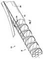
図1は、本実施形態の光ファイバケーブル10の部分切除図である。ケーブル10は、ジャケット30により包囲されたコア20を有している。ジャケット30は、コア20に向いた内面34と、外面38とを有している。ジャケット30は、主として一般に「ポリマー」と呼ばれることがある高分子物質で作られるのが良い。本明細書では、「ポリマー」という用語は、例えばコポリマー、及び例えば充填剤のような添加剤を含む高分子物質のような材料が挙げられる。コア20は、例えば、データ伝送及び/又は電力送電能力を備えた組立体又は構造体であるのが良い。図示の実施形態では、コア20は、逆螺旋巻き結合材44,46内に包まれた光ファイバ40の束を含む。 FIG. 1 is a partially cutaway view of an
ジャケット30は、コア20への接近を容易にする分離特徴部を有する。例示の実施形態では、分離特徴部は、ケーブル30の長さに沿って延びる一対の不連続部50である。本明細書では、「不連続部」という用語は、ジャケット30の主要部分とは異なる材料組成のジャケット30の一部分を示しており、主要部分は、参照符号55で示されている。主要部分55は、本質的に、コア20を包囲した環状フープであるのが良く、不連続部50は、ケーブル10の長さに沿って主要部分55を長手方向に貫通して延びている。一観点によれば、不連続部50は、図1に示されているようにジャケット30を分離することができる弱め線を提供する。不連続部50は、ジャケット30が比較的一様な環状体であるよう主要部分55の輪郭形状に合致するのが良い。 The
図2は、ケーブル10の長さに垂直な平面で取ったジャケット30を単独で示す断面図である。例示の実施形態では、不連続部50は、ジャケット30が押し出されたときにジャケット55の主要部分に結合される。主要部分55及び不連続部50は、押出し可能なポリマーで形成されるのが良く、従って、主要部分55及び不連続部50を形成するために用いられる押出し物が冷えて凝固すると、押出し物は、不連続部50の各側のインターフェース54のところで結合状態になる。不連続部50がジャケットの主要部分55と同一のステップで押し出されている間に形成されると、不連続部50とジャケット30の残部との結合部は、ジャケット30が凝固しているときに重合体(ポリマー)鎖のからみ合いによって形成可能であるとして一般に説明できる。したがって、ジャケット30は、凝集性複合構造体から成る。図2では、インターフェース54は、はっきりと記載された状態で示されているが、実際には、主要部分55と不連続部50の材料相互間の移行領域が存在すると言える。図2の不連続部50の湾曲“T”形状は、不連続部を形成するために使用できる一押出しプロセスの結果であるが、他の形状が採用可能である。 FIG. 2 is a cross-sectional view showing the
不連続部50は、ジャケット30内の比較的幅の狭いストリップであるのが良く、これら不連続部は、ジャケット断面積AJの比較的僅かな部分を占めるのが良い。例えば、不連続部50は、AJの10%未満であり且つAJの5%未満又は3%という低い割合の断面積ADを有するのが良い。図示の実施形態では、不連続部50は各々、AJの約3%である断面積ADを有する。図1及び図2では、2つの不連続部50が図1に示されているようにジャケットの開きを容易にするようジャケット30内に形成されている。コア20の取る形態に応じて、不連続部50の数、間隔、形状、組成及び他の観点は、様々であって良い。例えば、ジャケット30中の単一の不連続部は、ケーブルジャケット30を開いてコア20から遠ざけることができるのに十分な場合がある。図1の不連続部は、説明の目的上、長方形ストリップとして示されている。実際には、不連続部は、湾曲した形状又は不規則な形状のものであって良く、不連続部は、一般に、これら不連続部がジャケットの主要部分に取り付けられたままであるよう裂けるであろう。The
図3は、ジャケット30中の不連続部50のうちの1つを単独で示す図である。図示の実施形態では、不連続部50の幅Wは、不連続部50の半径方向内側部分のところよりもジャケット30の外面38の近くのところの方が非常に大きい。したがって、不連続部50は、ケーブルジャケット30の外面の僅かな目に見える部分を形成することができる。これは、例示のジャケットを形成するために用いられる製造プロセスに起因しており、かかる製造プロセスでは、不連続部50を形成するために用いられる押出し物を方向60からジャケットの外部中に導入し、そして主要部分55を形成するために用いられる押出し物材料中に内方に導入する。かくして、不連続部50は、これら不連続部が半径方向内方に延びるにつれて次第に幅が狭くなっている。不連続部は、ジャケット30中に深さDにわたって延び、ジャケット30は、厚さTを有している。この実施形態では、不連続部50は、本質的に、ジャケット30の外面38から内面34まで延びている。しかしながら、深さDは、厚さTに等しい必要はない。例えば、厚さTの少なくとも80%の深さDを有する不連続部は、ジャケット30を引き裂くための引き裂き場所を提供するのに効果的であると言える。厚さTの少なくとも50%の深さDを有する不連続部も又、ジャケット30を引き裂くための接近場所を提供する上で効果的であると言える。用いられるジャケット断面及び材料に応じて、少なくとも30%の深さDを有する不連続部は、コアへの接近を容易にするうえで効果的である場合がある。 FIG. 3 is a diagram independently showing one of the
図3に示されている幅Wは、不連続部50の最大幅に一致するのが良い。幅Wは、一般にジャケット30の周囲に沿って取った又はより具体的には不連続部50を二等分する半径に垂直に取った測定値である。幅Wは、度(°)で表された弧長としても表現できる。例えば、図3の実施形態に示されている不連続部50の最大幅Wは、0.5〜2.0mmであるのが良い。換言すると、不連続部は、その最大幅Wのところで、小さなケーブル直径に関し、ジャケット30の周囲に沿って20°未満の円弧にわたって横に延びるのが良い。不連続部は、大径ケーブルに関し、10°未満の円弧をなして横に延びるのが良い。 The width W shown in FIG. 3 should match the maximum width of the
不連続部50の極めて薄い「膜(フィルム)」型実施形態が採用される場合、不連続部の最大幅Wは、0.2mm以下の範囲にあるのが良く、約0.1mmであるのが良く、これは、1°以下の円弧に相当している。換言すると、不連続部は、その最大幅Wのところで、ジャケット30の周囲に沿って2°未満の円弧にわたって横に延びるのが良い。 When a very thin “film” type embodiment of the
主要部分55及び不連続部50を形成するために用いられる材料及び方法は、インターフェース54が図1に示されているようにジャケット30を引き裂くことによってコア20への比較的容易な接近を可能にするよう選択されるのが良い。ケーブル10は、堅牢さに関する他の要件、例えば、ジャケット30が引張り荷重を受け、捩りを受け、温度変化状態にあり、更に他の既知のケーブル試験基準、例えばICEA460及びGR20を受けたときに無傷のままであるようにするための要件を満足するよう構成されているのが良い。 The materials and methods used to form the
図示のジャケット30の主要部分55は、中密度ポリエチレン(MDPE)から押出し成形されており、不連続部50は、ポリプロピレン(PP)から押出し成形されている。ジャケット30は、同時押出し成形法で形成されており、その結果、主要部分55と不連続部50は、冷却中に結合され、それにより、インターフェース54のところに比較的強固な結合部が形成されている。この方法で形成されたケーブル(図示せず)は、ケーブル20中に結合材としての細線の下に吸水膨潤性テープを更に有している。ケーブルジャケット30は、堅牢であるが、ジャケット30を不連続部50に沿って剪断し又は引き裂くのに比較的弱い引張り力で十分である。 The
理論に束縛されるものではないが、本出願人は、ポリプロピレンとポリエチレン(PE)との結合は、ポリエチレン(PE)と結合するポリプロピレン中に混合されたエチレンの量と、PEとPPとの分子からみ合いの、一方又は両方によって引き起こされると確信している。この理解によれば、不連続部とジャケットの残部との結合を強化するにはPP押出し物中のエチレンの量を増大させるのが良い。一般に、ジャケット30の主要部分55が、第1のポリマー材料で作られ、不連続部が第2のポリマー材料で作られる場合、不連続部は、0.5重量%〜20重量%の第1のポリマー材料を含むのが良い。 Without being bound by theory, Applicants believe that the bond between polypropylene and polyethylene (PE) is the amount of ethylene mixed in the polypropylene that binds to polyethylene (PE) and the molecules of PE and PP. I am sure it is caused by one or both of the entanglements. According to this understanding, the amount of ethylene in the PP extrudate may be increased to strengthen the bond between the discontinuities and the remainder of the jacket. Generally, when the
幅の狭い薄膜不連続部50がジャケット中に設けられる場合、不連続部中の第1のポリマーの含有量は、図2の実施形態とほぼ同じであるのが良い。一実施形態としての薄膜不連続部は、約9%PEの入ったPPから成る。これよりも高いPE含有量、例えば最高20%までのPEも又採用可能である。PP中に0.2%未満のPE含有量は、結果的に、主要部分と不連続部との間に不十分な結合をもたらす場合がある。 When the thin film
不連続部50をジャケット30中に設けることにより、従来型ケーブルでは不可能なケーブル接近手順が可能である。図1及び図2を参照すると、ケーブル10に接近するには、不連続部50の近くで無傷のケーブルの端部をすじ付けするのが良い。ケーブル端部は、例えば、1本のスニップ、ナイフ又は他の何らかのブレード付き器具によってすじ付け可能である。次に、引き裂かれたジャケット30の一方の側部又は両方の側部を図1に示すように引き戻すのが良く、ジャケット30は、不連続部50の存在によって作られている平面に沿って裂ける。コア20への接近を可能にするためにジャケット30の一方の側部又は両方の側部をケーブル10に沿う所望の長さまで引き戻すのが良い。不連続部は、一般に、これら不連続部がジャケット30の主要部分55のそれぞれの側部にくっついた状態で裂けるのに十分細い。ケーブル10の全長に沿って延びる不連続部は、この方法に従ってコア20への接近を可能にするうえで効果的である。しかしながら、これよりも短い不連続部長さも又効果的である場合がある。例えば、ケーブルの長さに沿って少なくとも10センチメートルの長さの不連続部で十分な場合がある。不連続部50は、主要部分55とは異なる色のものであるのが良く、その結果、不連続部の存在場所を容易に突き止めることができ、しかもケーブル外部から目に見える。不連続部50がケーブルの全長よりも短いジャケットに沿う長さにわたって延びる場合、不連続部50の異なる着色は、技術者がケーブル30上の接近可能場所を見出すのを助けることができる。 By providing the
ケーブル10は、既存の同時押出し機器に小規模な改造を施した状態で用いて製造できる。例えば、デビス‐スタンダード(Davis-Standard)社のワイヤ種目からの押出し機及びケーブル押出し機を用いると、本発明の実施形態に従ってケーブルジャケットを形成することができる。例えば、1.5インチ(40mm)バレル直径押出し機及びこれよりも大径のバレル直径押出し機、例えばデビス‐スタンダード社から入手できる3.4又は4.5インチ(1インチ=25.4mm)押出し機を、大径押出し機でケーブルジャケットを押し出し、小径押出し機でケーブルジャケットの外部にストライプを押し出すために従来用いられる形態のクロスヘッドにねじ込むのが良い。従来プロセスでは、ストライプ押出し物材料をジャケット押出し物の表面上に被着させる。本発明の実施形態によれば、ジャケット押出し機中の押出し物の流れは、ストライプ押出し物材料がジャケット押出し物中に導入される1つ又は複数の場所のところにそらされる。ジャケット押出し物をそらすことにより、ジャケット押出し物の流れ中に窪み又はトラフが作られ、不連続部を形成するために用いられる押出し物材料がこの窪み又はトラフ中に導入される。次に、ジャケット押出し物は、この中に形成された不連続部と一緒に、収縮してクロスヘッドを通って前進している光ファイバコアの周りに凝固する。 The
図4は、同時押出し装置100の切除断面図であり、この同時押出し装置をクロスヘッドにねじ込んでこれを用いて本発明の実施形態のケーブルを製造することができる。図4の矢印は、押出し物の流れ方向を示している。図5は、ジャケット30を形成する押出し物材料の表示を含む同時押出し装置100を示している。装置100は、一般に、以下に説明する改造を除き、ストライプをケーブルジャケット上に押し出す能力を備えた状態のケーブル被覆ラインで用いられる市販のコンポーネントから構成可能である。図4及び図5を参照すると、装置100は、ジャケット30の主要部分55を形成するために用いられる第1の溶融押出し物材料112を受け入れる第1の入力ポート110を有している。第2の入力ポート120により、不連続部50を形成するために用いられる第2の溶融押出し物材料122の導入が可能である。キャビティ130が押出しコーン136の形状を部分的に定め、ケーブルジャケットの最終的形態を定める先端部(図示せず)を収容している。 FIG. 4 is a cutaway sectional view of the
図6は、装置100中に挿入されるリング150を示しており、このリングにより、第1の押出し物材料112の流れ中に不連続部を形成することができる。リング150は、第1の押出し物112の流れをそらすよう働く2つの突出部152を有している。突出部152は、第1の押出し物112の流れをそらして押出し物流れ中にトラフ又は窪みを形成し、第2の押出し物材料122は、図5に示されているようにこのトラフ又は窪み中に流れる。 FIG. 6 shows a
図5を参照すると、光ファイバケーブル10を形成するため、ケーブルコア(図示せず)を装置100の中心線102に沿って前進させる。第1の押出し物材料112を第1の入力ポート110中に圧送し、第1の押出し物材料は、次に、装置100に設けられているチャネルを通って前進し、そして先端部(図示せず)上でこれに沿って移動する。突出部152は、押出し物112の流れをそらしてトラフを形成する。これらの場所において、第2の押出し物材料122をトラフ中に導入する。したがって、第2の押出し物材料122は、ジャケットが押し出されているとき、第1の押出し物材料112の流れ中において液体として流れる。第1及び第2の押出し物材料112,122で構成された押出しコーン136は、冷えてコアの周りに凝固し、それによりジャケット30が形成される。 Referring to FIG. 5, a cable core (not shown) is advanced along the centerline 102 of the
図7は、第2の実施形態としての光ファイバケーブル310の部分切除図である。ケーブル310は、図1に示された実施形態と同様、ジャケット330で包囲されたコア320を有している。ジャケット330は、ケーブル330の長さに沿って延びる一対の不連続部350を有している。この実施形態では、不連続部350は、比較的互いに密接しており(例えば、互いに90°以内に位置している)、従って、ジャケット330の幅の狭いストリップをコア320から引き剥がすことができるようになっている。 FIG. 7 is a partial cutaway view of an
本明細書において説明しているケーブルジャケット主要部分55,355及び不連続部50,350は、種々のポリマー材料で構成できる。主要部分か不連続部かのいずれかは、ポリプロピレン(PP)、ポリエチレン(PE)又はこれら材料の配合物、例えばPEとエチレンビニルアセテート(EVA)の配合物、難燃性材料、例えば難燃性ポリエチレン、難燃性ポリプロピレン、ポリ塩化ビニル(PVC)又はポリビニリデンフルオリド(PVDF)、充填材料、例えばポリブチレンテレフタレート(PBT)、ポリカーボネート及び/又はポリエチレン(PE)材料及び/又はエチレンビニルアセテート(EVA)又はチョーク、タルク等のような充填剤を含むこれらの他の配合物及び他の材料、例えばUV硬化性アクリレートで構成できる。 The cable jacket
例示の実施形態では、第1の材料は、少なくとも80重量%の第1のポリマー、即ちポリエチレンを含むのが良く、第2の材料は、少なくとも70重量%の第2のポリマー、即ちポリプロピレン及び少なくとも0.5重量%の第1のポリマー、即ちポリエチレンを含む。第1のポリマーの重量でこれよりも多い量、例えば少なくとも1.0重量%又は少なくとも2重量%を第2の材料中に含有させても良い。 In an exemplary embodiment, the first material may comprise at least 80% by weight of the first polymer, ie polyethylene, and the second material comprises at least 70% by weight of the second polymer, ie polypropylene and at least 0.5% by weight of the first polymer, ie polyethylene. Higher amounts by weight of the first polymer, such as at least 1.0 wt% or at least 2 wt% may be included in the second material.
変形実施形態では、ポリプロピレンをジャケットの主要部分の第1のポリマー主要成分として用いるのが良く、ポリエチレンを不連続部の主要成分として用いるのが良い。この場合、ポリプロピレンの量をポリエチレン不連続部に追加すると、不連続部と主要部分との結合が促進される。 In an alternative embodiment, polypropylene may be used as the first polymer main component of the main portion of the jacket, and polyethylene may be used as the main component of the discontinuity. In this case, adding the amount of polypropylene to the polyethylene discontinuity promotes the bond between the discontinuity and the main portion.
一般に、本明細書において開示した所望の分離特性は、ジャケットの主要部分を形成するために用いられる材料とは異なる材料から不連続部を同時押出し成形することによって得られる。別の方法として、不連続部をジャケットの残部と同種の材料で作ることができるが、かかる不連続部に例えば別の硬化条件を課すのが良い。 In general, the desired separation characteristics disclosed herein are obtained by coextrusion of discontinuities from a different material than that used to form the main portion of the jacket. Alternatively, the discontinuities can be made of the same material as the rest of the jacket, but it is possible to impose different curing conditions on such discontinuities, for example.
図示のコアは、光ファイバ通信信号を伝送することができる。光ファイバに加えて又は光ファイバの代替手段として、電気導体をケーブルコア中に設けても良く、その結果、コアは、電気通信信号を伝送することができる。 The illustrated core can transmit optical fiber communication signals. In addition to or as an alternative to optical fiber, electrical conductors may be provided in the cable core so that the core can transmit telecommunication signals.
特許請求の範囲に記載された本発明の範囲に含まれる多くの改造例及び他の実施形態が当業者には明らかであろう。例えば、本発明の技術的思想を任意適当な光ファイバケーブル設計及び/又は製造方法に利用することができる。かくして、本発明は、当業者に明らかなこれら改造例及び実施形態をも含むものである。 Many modifications and other embodiments within the scope of the invention as set forth in the claims will be apparent to those skilled in the art. For example, the technical idea of the present invention can be applied to any appropriate optical fiber cable design and / or manufacturing method. Thus, the present invention includes these modifications and embodiments that will be apparent to those skilled in the art.
Claims (4)
Translated fromJapanese少なくとも1本の光ファイバを含むコアと、
前記コアを包囲したジャケットとを有し、前記ジャケットは、
第1の押出しポリマー材料の主要部分と、
前記主要部分中に結合された第2の押出しポリマー材料の少なくとも1つの不連続部とを有し、前記不連続部は、ケーブルの長さに沿って延び、前記第1の押出しポリマー材料は、前記第2の押出しポリマー材料とは異なっており、
前記不連続部と前記主要部分との結合部は、前記コアへの接近を可能にするよう前記ジャケットを前記不連続部のところで分離することができるようなものであり、
前記第1の押出しポリマー材料は、少なくとも80重量パーセントの第1のポリマーを含み、前記第2の押出しポリマー材料は、少なくとも70重量パーセントの第2のポリマー及び少なくとも0.5重量パーセントの前記第1のポリマーを含む、ケーブル。A cable,
A core comprising at least one optical fiber;
A jacket surrounding the core, the jacket
A major portion of a first extruded polymeric material;
At least one discontinuity of a second extruded polymer material bonded in the main portion, the discontinuity extending along the length of the cable,the first extruded polymer material comprising: Different fromthe second extruded polymer material ,
The joint between the discontinuity and the main part is such that the jacket can be separated at the discontinuity to allow access to the core;
Before SL first extruded polymeric material comprises a first polymer of at least 80% by weight, said second extruded polymeric material, said second polymer and at least 0.5% by weight of at least 70 weight percent of the A cable comprising one polymer.
Applications Claiming Priority (3)
| Application Number | Priority Date | Filing Date | Title |
|---|---|---|---|
| US33003810P | 2010-04-30 | 2010-04-30 | |
| US61/330,038 | 2010-04-30 | ||
| PCT/US2011/034309WO2011137236A1 (en) | 2010-04-30 | 2011-04-28 | Fiber optic cables with access features and methods of making fiber optic cables |
Related Child Applications (1)
| Application Number | Title | Priority Date | Filing Date |
|---|---|---|---|
| JP2016189338ADivisionJP2017021372A (en) | 2010-04-30 | 2016-09-28 | Optical fiber cable with access feature and method of manufacturing the same |
Publications (3)
| Publication Number | Publication Date |
|---|---|
| JP2013531805A JP2013531805A (en) | 2013-08-08 |
| JP2013531805A5 JP2013531805A5 (en) | 2014-06-05 |
| JP6017415B2true JP6017415B2 (en) | 2016-11-02 |
Family
ID=44246147
Family Applications (2)
| Application Number | Title | Priority Date | Filing Date |
|---|---|---|---|
| JP2013508249AExpired - Fee RelatedJP6017415B2 (en) | 2010-04-30 | 2011-04-28 | Optical fiber cable with access feature and method of manufacturing the same |
| JP2016189338APendingJP2017021372A (en) | 2010-04-30 | 2016-09-28 | Optical fiber cable with access feature and method of manufacturing the same |
Family Applications After (1)
| Application Number | Title | Priority Date | Filing Date |
|---|---|---|---|
| JP2016189338APendingJP2017021372A (en) | 2010-04-30 | 2016-09-28 | Optical fiber cable with access feature and method of manufacturing the same |
Country Status (3)
| Country | Link |
|---|---|
| US (3) | US9073243B2 (en) |
| JP (2) | JP6017415B2 (en) |
| WO (1) | WO2011137236A1 (en) |
Families Citing this family (44)
| Publication number | Priority date | Publication date | Assignee | Title |
|---|---|---|---|---|
| US20100278492A1 (en)* | 2009-04-30 | 2010-11-04 | Bohler Gregory B | Armored Fiber Optic Assemblies and Methods of Forming Fiber Optic Assemblies |
| EP3929644A1 (en) | 2010-03-02 | 2021-12-29 | Commscope Technologies LLC | Fiber optic cable assembly |
| JP6017415B2 (en) | 2010-04-30 | 2016-11-02 | コーニング オプティカル コミュニケイションズ リミテッド ライアビリティ カンパニー | Optical fiber cable with access feature and method of manufacturing the same |
| CN103221862B (en) | 2010-10-28 | 2016-10-26 | 康宁光缆系统有限责任公司 | Fiber optic cable with extruded access features and method for making fiber optic cable |
| WO2012071490A2 (en)* | 2010-11-23 | 2012-05-31 | Corning Cable Systems Llc | Fiber optic cables with access features |
| US9081161B2 (en)* | 2011-01-31 | 2015-07-14 | Afl Telecommunications Llc | All-dielectric self-supporting (ADSS) fiber optic cable with a semi-conducting co-extruded tracking resistant jacket |
| US9274302B2 (en) | 2011-10-13 | 2016-03-01 | Corning Cable Systems Llc | Fiber optic cables with extruded access features for access to a cable cavity |
| US9323022B2 (en) | 2012-10-08 | 2016-04-26 | Corning Cable Systems Llc | Methods of making and accessing cables having access features |
| US8682124B2 (en) | 2011-10-13 | 2014-03-25 | Corning Cable Systems Llc | Access features of armored flat fiber optic cable |
| US9201208B2 (en) | 2011-10-27 | 2015-12-01 | Corning Cable Systems Llc | Cable having core, jacket and polymeric jacket access features located in the jacket |
| US9176293B2 (en) | 2011-10-28 | 2015-11-03 | Corning Cable Systems Llc | Buffered fibers with access features |
| US9475239B2 (en) | 2011-11-01 | 2016-10-25 | Corning Cable Systems Llc | Cables with extruded access features and methods of making thereof |
| US8620123B2 (en) | 2012-02-13 | 2013-12-31 | Corning Cable Systems Llc | Visual tracer system for fiber optic cable |
| US8909014B2 (en) | 2012-04-27 | 2014-12-09 | Corning Cable Systems Llc | Fiber optic cable with access features and jacket-to-core coupling, and methods of making the same |
| EP3432047A1 (en) | 2012-05-02 | 2019-01-23 | Fujikura Ltd. | Round and small diameter optical cables with a ribbon-like optical fiber structure |
| US8705921B2 (en)* | 2012-07-27 | 2014-04-22 | Corning Cable Systems Llc | Fiber optic drop cable |
| US9669592B2 (en) | 2012-07-27 | 2017-06-06 | Corning Optical Communications LLC | Method of manufacturing a fiber optic drop cable |
| US8620124B1 (en) | 2012-09-26 | 2013-12-31 | Corning Cable Systems Llc | Binder film for a fiber optic cable |
| US9091830B2 (en) | 2012-09-26 | 2015-07-28 | Corning Cable Systems Llc | Binder film for a fiber optic cable |
| US11287589B2 (en) | 2012-09-26 | 2022-03-29 | Corning Optical Communications LLC | Binder film for a fiber optic cable |
| US9482839B2 (en) | 2013-08-09 | 2016-11-01 | Corning Cable Systems Llc | Optical fiber cable with anti-split feature |
| US9075212B2 (en) | 2013-09-24 | 2015-07-07 | Corning Optical Communications LLC | Stretchable fiber optic cable |
| US8805144B1 (en) | 2013-09-24 | 2014-08-12 | Corning Optical Communications LLC | Stretchable fiber optic cable |
| US8913862B1 (en) | 2013-09-27 | 2014-12-16 | Corning Optical Communications LLC | Optical communication cable |
| US9594226B2 (en) | 2013-10-18 | 2017-03-14 | Corning Optical Communications LLC | Optical fiber cable with reinforcement |
| EP3090296B1 (en)* | 2013-12-30 | 2019-02-27 | Corning Optical Communications LLC | A fiber optic cable with a binder film system |
| US10379309B2 (en) | 2014-11-18 | 2019-08-13 | Corning Optical Communications LLC | Traceable optical fiber cable and filtered viewing device for enhanced traceability |
| US10228526B2 (en) | 2015-03-31 | 2019-03-12 | Corning Optical Communications LLC | Traceable cable with side-emitting optical fiber and method of forming the same |
| US10101553B2 (en) | 2015-05-20 | 2018-10-16 | Corning Optical Communications LLC | Traceable cable with side-emitting optical fiber and method of forming the same |
| EP3326014A1 (en) | 2015-07-17 | 2018-05-30 | Corning Optical Communications LLC | Systems and methods for tracing cables and cables for such systems and methods |
| EP3325876A1 (en) | 2015-07-17 | 2018-05-30 | Corning Optical Communications LLC | Systems and methods for traceable cables |
| MX2018002935A (en)* | 2015-09-28 | 2018-06-15 | Dow Global Technologies Llc | Peelable cable jacket having designed microstructures and methods for making peelable cable jackets having designed microstructures. |
| US10101545B2 (en) | 2015-10-30 | 2018-10-16 | Corning Optical Communications LLC | Traceable cable assembly and connector |
| WO2017158470A1 (en)* | 2016-03-14 | 2017-09-21 | 3M Innovative Properties Company | Cable assembly with a removable installation device |
| CN109154701A (en) | 2016-04-08 | 2019-01-04 | 康宁研究与开发公司 | With light structures and for carrying the traceable fiber optical cable assembly from the tracking optical fiber of the received light of light originating device |
| US10107983B2 (en) | 2016-04-29 | 2018-10-23 | Corning Optical Communications LLC | Preferential mode coupling for enhanced traceable patch cord performance |
| WO2017209983A1 (en)* | 2016-05-31 | 2017-12-07 | Corning Optical Communications LLC | Optical fiber cable with wrapped, welded jacket and method of manufacturing |
| US10222560B2 (en) | 2016-12-21 | 2019-03-05 | Corning Research & Development Corporation | Traceable fiber optic cable assembly with fiber guide and tracing optical fibers for carrying light received from a light launch device |
| US10234614B2 (en) | 2017-01-20 | 2019-03-19 | Corning Research & Development Corporation | Light source assemblies and systems and methods with mode homogenization |
| US10539747B2 (en) | 2017-12-05 | 2020-01-21 | Corning Research & Development Corporation | Bend induced light scattering fiber and cable assemblies and method of making |
| US10539758B2 (en) | 2017-12-05 | 2020-01-21 | Corning Research & Development Corporation | Traceable fiber optic cable assembly with indication of polarity |
| CN109575558A (en)* | 2018-11-28 | 2019-04-05 | 山东利特纳米技术有限公司 | A kind of polymer composite and preparation method thereof for notebook computer casing |
| EP3690510A1 (en) | 2019-02-04 | 2020-08-05 | Max-Planck-Gesellschaft zur Förderung der Wissenschaften e.V. | Method of and apparatus for imaging light emitting objects on an image sensor |
| US11215777B2 (en) | 2019-07-31 | 2022-01-04 | Corning Research & Development Corporation | Cable skin layer with access sections integrated into a cable jacket |
Family Cites Families (147)
| Publication number | Priority date | Publication date | Assignee | Title |
|---|---|---|---|---|
| US3076235A (en) | 1960-03-09 | 1963-02-05 | Superior Cable Corp | Method for striping conductor coatings |
| US3991014A (en) | 1974-05-10 | 1976-11-09 | E. I. Du Pont De Nemours And Company | Polyesters of derivatives of hydroquinone and bis(carboxyphenyl)ether |
| US4083829A (en) | 1976-05-13 | 1978-04-11 | Celanese Corporation | Melt processable thermotropic wholly aromatic polyester |
| US4067852A (en) | 1976-05-13 | 1978-01-10 | Celanese Corporation | Melt processable thermotropic wholly aromatic polyester containing polybenzoyl units |
| SE7706752L (en) | 1977-06-09 | 1978-12-10 | Ericsson Telefon Ab L M | CABLE WITH CUTTING WIRE |
| US4130545A (en) | 1977-09-12 | 1978-12-19 | Celanese Corporation | Melt processable thermotropic wholly aromatic polyester comprising both para-oxybenzoyl and meta-oxybenzoyl moieties |
| US4248824A (en)* | 1979-01-24 | 1981-02-03 | Alcan Aluminum Corporation | Method and apparatus for striping extruded polymer products |
| EP0020036B1 (en) | 1979-05-22 | 1982-08-11 | The Post Office | Improved communications cable |
| US4318842A (en) | 1980-10-06 | 1982-03-09 | Celanese Corporation | Polyester of 6-hydroxy-2-naphthoic acid, aromatic diol, and 1,4-cyclohexanedicarboxylic acid capable of undergoing melt processing |
| US4468364A (en) | 1983-04-28 | 1984-08-28 | Celanese Corporation | Process for extruding thermotropic liquid crystalline polymers |
| JPS6091306A (en) | 1983-10-25 | 1985-05-22 | Hitachi Cable Ltd | Reinforcing method of connection part terminal of multicore optical fiber |
| DE3564493D1 (en) | 1984-06-19 | 1988-09-22 | Telephone Cables Ltd | Optical fibre cables |
| CN1004772B (en) | 1985-05-06 | 1989-07-12 | 电话电报有限公司 | Optical cable |
| DE3624124A1 (en) | 1986-07-17 | 1988-01-21 | Kabelmetal Electro Gmbh | MESSAGE CABLES WITH FOCUS |
| US4729628A (en) | 1986-11-14 | 1988-03-08 | Siecor Corporation | Fiber optic dropwire |
| JPS63120206U (en) | 1987-01-29 | 1988-08-03 | ||
| GB2206976B (en) | 1987-07-10 | 1991-01-30 | Stc Plc | Optical fibre cable |
| DE3743334C1 (en)* | 1987-12-21 | 1989-05-24 | Standard Elektrik Lorenz Ag | Optical cable |
| JPH01245208A (en) | 1988-03-28 | 1989-09-29 | Fujikura Ltd | Production of split type optical fiber tape fiber |
| DE3922475A1 (en) | 1989-07-06 | 1991-01-17 | Siemens Ag | OPTICAL NEWS CABLE |
| DE4142047C2 (en) | 1991-12-19 | 2001-03-01 | Siemens Ag | Method for covering at least one optical waveguide with a protective layer and for attaching reinforcing elements |
| IT1271484B (en) | 1993-10-12 | 1997-05-28 | Alcatel Cavi Spa | MODULAR OPTICAL FIBER TAPE, SEPARABLE INTO A PLURALITY OF TAPES OR MODULES, PROCEDURE FOR MANUFACTURING SUCH TAPE AND OPTICAL CABLE USING THE SAME |
| US5469523A (en) | 1994-06-10 | 1995-11-21 | Commscope, Inc. | Composite fiber optic and electrical cable and associated fabrication method |
| DE4421456A1 (en) | 1994-06-18 | 1995-12-21 | Kwo Kabel Gmbh | Accurate embedded of optical fibres and tensile elements in a thermoplastic |
| US5442722A (en) | 1994-07-25 | 1995-08-15 | Siecor Corporation | Optical fiber ribbon with zip cord |
| FR2728977B1 (en) | 1995-01-02 | 1997-01-31 | Alcatel Cable | QUICK AND EASY STRIPPING OPTICAL FIBER CABLE |
| FR2735604B1 (en) | 1995-06-14 | 1997-07-18 | Schneider Electric Sa | FLAT CABLE AND STRIPPING PLIERS |
| US5668912A (en) | 1996-02-07 | 1997-09-16 | Alcatel Na Cable Systems, Inc. | Rectangular optical fiber cable |
| DE19605276A1 (en) | 1996-02-13 | 1997-08-14 | Siemens Ag | Method and device for manufacturing an optical cable |
| JPH09230184A (en)* | 1996-02-22 | 1997-09-05 | Mitsubishi Cable Ind Ltd | Optical fiber tape |
| JP3172084B2 (en) | 1996-03-12 | 2001-06-04 | 日本電信電話株式会社 | Optical flat cable |
| US5949940A (en) | 1997-05-27 | 1999-09-07 | Corning Incorporated | Enhanced ribbon strippability using coating additives |
| US5717805A (en) | 1996-06-12 | 1998-02-10 | Alcatel Na Cable Systems, Inc. | Stress concentrations in an optical fiber ribbon to facilitate separation of ribbon matrix material |
| US6167180A (en) | 1997-09-12 | 2000-12-26 | Alcatel | Cable having at least one layer of flexible strength members with adhesive and non-adhesive yarns for coupling an outer protective jacket and a buffer tube containing optical fibers |
| US5970196A (en) | 1997-09-22 | 1999-10-19 | Siecor Corporation | Fiber optic protective member with removable section to facilitate separation thereof |
| US6088499A (en) | 1997-09-30 | 2000-07-11 | Siecor Corporation | Fiber optic cable with ripcord |
| US5987204A (en) | 1997-10-14 | 1999-11-16 | 3M Innnvative Properties Company | Cable with predetermined discrete connectorization locations |
| GB2331374A (en) | 1997-11-18 | 1999-05-19 | Northern Telecom Ltd | A Removably Coated Optical Fibre |
| US6101305A (en) | 1997-12-15 | 2000-08-08 | Siecor Corporation | Fiber optic cable |
| US6041153A (en) | 1998-07-01 | 2000-03-21 | Alcatel | Continuous composite reinforced buffer tubes for optical fiber cables |
| US6377738B1 (en) | 1998-12-04 | 2002-04-23 | Pirelli Cable Corporation | Optical fiber cable and core with a reinforced buffer tube having visible strength members and methods of manufacture thereof |
| JP4489305B2 (en) | 1999-03-16 | 2010-06-23 | 浜松ホトニクス株式会社 | High-speed visual sensor device |
| FR2793565B1 (en) | 1999-05-12 | 2002-05-24 | Sagem | OPTICAL FIBER CABLE HAVING LONGITUDINAL REINFORCEMENTS |
| JP2001023445A (en)* | 1999-07-06 | 2001-01-26 | Sumitomo Electric Ind Ltd | Plastic coated cable and method of manufacturing the same |
| US6137936A (en) | 1999-07-22 | 2000-10-24 | Pirelli Cables And Systems Llc | Optical fiber cable with single strength member in cable outer jacket |
| US6404962B1 (en) | 1999-09-15 | 2002-06-11 | Fitel Usa Corp. | Groups of optical fibers closely bound by easily removable buffer encasements, and associated fiber optic cables |
| GB2355335B (en) | 1999-10-16 | 2004-01-21 | Raydex Cdt Ltd | Improvements in or relating to cables |
| US6545222B2 (en) | 2000-01-11 | 2003-04-08 | Sumitomo Electric Industries, Ltd. | Cable, and method for removing sheath at intermediate part of cable |
| US6483972B1 (en) | 2000-04-06 | 2002-11-19 | Alcatel | Edge-bonded splittable optical-fiber ribbon |
| JP2001318286A (en)* | 2000-05-12 | 2001-11-16 | Yazaki Corp | Optical fiber cable and combined power / optical cable |
| US7113679B2 (en) | 2000-05-26 | 2006-09-26 | Corning Cable Systems, Llc | Fiber optic drop cables and preconnectorized assemblies having toning portions |
| US6542674B1 (en) | 2000-08-25 | 2003-04-01 | Corning Cable Systems Llc | Fiber optic cables with strength members |
| DE10028562A1 (en) | 2000-06-09 | 2001-12-13 | Scc Special Comm Cables Gmbh | Air cable containing optical transmission elements and method of manufacturing an air cable |
| US6563991B1 (en) | 2000-06-13 | 2003-05-13 | Alcatel | Optical fiber cable for easy access to ripcords and having ripcord reliability |
| US6603908B2 (en)* | 2000-08-04 | 2003-08-05 | Alcatel | Buffer tube that results in easy access to and low attenuation of fibers disposed within buffer tube |
| US6704481B2 (en) | 2000-12-29 | 2004-03-09 | Alcatel | Cable assembly having ripcords with excess length and ripcords attached to tape |
| ITMI20010094A1 (en) | 2001-01-19 | 2002-07-19 | Testa Engineering S R L | MACHINE FOR WINDING IN ROLLS AND / OR PACKING OF ROLLS OF FABRICS AND SIMILAR |
| US7346244B2 (en) | 2001-03-23 | 2008-03-18 | Draka Comteq B.V. | Coated central strength member for fiber optic cables with reduced shrinkage |
| JP2002328277A (en) | 2001-04-26 | 2002-11-15 | Fujikura Ltd | Optical cable |
| US6731844B2 (en) | 2001-06-21 | 2004-05-04 | Corning Cable Systems Llc | Identification of optical ribbons |
| US6661956B2 (en) | 2001-07-10 | 2003-12-09 | Corning Cable Systems Llc | Optical fiber cable for use in a dispersion managed cable system |
| US6728455B2 (en) | 2001-09-04 | 2004-04-27 | Fujikura Ltd. | Optical fiber drop cable and manufacturing method thereof |
| US20030094298A1 (en)* | 2001-11-20 | 2003-05-22 | Commscope Properties, Llc | Toneable conduit and method of preparing same |
| BR0116824B1 (en) | 2001-11-28 | 2011-05-03 | telecommunication cable | |
| US6813421B2 (en) | 2001-12-26 | 2004-11-02 | Corning Cable Systems Llc | Fiber optic cable having a ripcord |
| CA2475970A1 (en) | 2002-05-28 | 2003-12-04 | Kaoru Okuno | Optical fiber tape core |
| US6792184B2 (en) | 2002-05-31 | 2004-09-14 | Corning Cable Systems Llc | Optical fiber ribbons having a preferential separation sequence |
| DE10228439A1 (en) | 2002-06-26 | 2004-01-22 | Degussa Ag | Plastic optical fiber |
| GB0313018D0 (en) | 2002-08-10 | 2003-07-09 | Emtelle Uk Ltd | Signal transmitting cable |
| CA2496030A1 (en) | 2002-08-20 | 2004-03-04 | Sumitomo Electric Industries, Ltd. | Tool and method for assembling linear elements into ribbon shape, and linear elements assembled into ribbon shape and terminal portion structure of the same |
| JP2004077888A (en)* | 2002-08-20 | 2004-03-11 | Daiden Co Ltd | Electrical wire cable and optical cable |
| US7049523B2 (en) | 2002-08-30 | 2006-05-23 | Belden Technologies, Inc. | Separable multi-member composite cable |
| US7050685B2 (en) | 2002-10-01 | 2006-05-23 | Alcatel | Cable easy access tape with perforated, peelable sections |
| US6957000B2 (en) | 2002-10-31 | 2005-10-18 | Corning Cable Systems Llc | Peelable buffer layer having a preferential tear portion and methods of manufacturing the same |
| JP2005148373A (en) | 2003-11-14 | 2005-06-09 | Ube Nitto Kasei Co Ltd | FRP tensile body and drop optical fiber cable |
| US7471862B2 (en) | 2002-12-19 | 2008-12-30 | Corning Cable Systems, Llc | Dry fiber optic cables and assemblies |
| US20090190890A1 (en) | 2002-12-19 | 2009-07-30 | Freeland Riley S | Fiber optic cable having a dry insert and methods of making the same |
| US7415181B2 (en) | 2005-07-29 | 2008-08-19 | Corning Cable Systems Llc | Fiber optic cables and assemblies for fiber to the subscriber applications |
| US7029137B2 (en) | 2003-02-13 | 2006-04-18 | Dell Products L.P. | Cable having an illuminating tracer element mounted thereon |
| US6876798B2 (en) | 2003-08-29 | 2005-04-05 | Corning Cable Systems Llc | Fiber optic cable having a ripcord |
| DE102004015957A1 (en) | 2004-03-31 | 2005-10-27 | CCS Technology, Inc., Wilmington | Mechanically separable cable |
| JP2005345622A (en) | 2004-06-01 | 2005-12-15 | Sumitomo Electric Ind Ltd | Fiber optic cable |
| DE102004035809A1 (en)* | 2004-07-23 | 2006-03-16 | CCS Technology, Inc., Wilmington | Optical cable and method of making an optical cable |
| US7218821B2 (en) | 2004-08-20 | 2007-05-15 | Furukawa Electric North America Inc. | Optical fiber cables |
| US20060045443A1 (en) | 2004-08-30 | 2006-03-02 | Blazer Bradley J | Fiber optic ribbons having one or more preferential tear portions and method of making the same |
| US7123801B2 (en) | 2004-11-18 | 2006-10-17 | Prysmian Communications Cables And Systems Usa, Llc | Optical fiber cable with fiber receiving jacket ducts |
| JP2006162703A (en) | 2004-12-02 | 2006-06-22 | Furukawa Electric Co Ltd:The | Fiber optic cable |
| US7197215B2 (en)* | 2004-12-15 | 2007-03-27 | Corning Cable Systems, Llc. | Fiber optic cables with easy access features |
| JP2006171570A (en) | 2004-12-17 | 2006-06-29 | Sumitomo Electric Ind Ltd | Fiber optic cable |
| US7206481B2 (en) | 2004-12-21 | 2007-04-17 | Corning Cable Systems, Llc. | Fiber optic cables manufactured as an assembly and method for manufacturing the same |
| US7187830B2 (en) | 2004-12-22 | 2007-03-06 | Corning Cable Systems, Llc. | Optical fiber ribbons having a preferential tear portion formed by curing and methods therefor |
| KR100802795B1 (en) | 2005-01-07 | 2008-02-12 | 엘에스전선 주식회사 | Pneumatic installation optical fiber cable with tension cord with lip cord function |
| US7379642B2 (en) | 2005-01-18 | 2008-05-27 | Adc Telecommunications, Inc. | Low shrink telecommunications cable and methods for manufacturing the same |
| JP4252991B2 (en) | 2005-02-10 | 2009-04-08 | 古河電気工業株式会社 | Optical fiber cable, optical fiber extraction method, and optical fiber extraction tool |
| JP4297372B2 (en) | 2005-02-10 | 2009-07-15 | 古河電気工業株式会社 | Optical fiber cable, optical fiber extraction method, and optical fiber extraction tool |
| US7225534B2 (en) | 2005-02-11 | 2007-06-05 | Adc Telecommunications, Inc. | Telecommunications cable jacket adapted for post-extrusion insertion of optical fiber and methods for manufacturing the same |
| US7203404B2 (en) | 2005-02-28 | 2007-04-10 | Corning Cable Systems, Llc. | Loose tube fiber optic cables having at least one access location |
| DE102005012690A1 (en) | 2005-03-18 | 2006-09-28 | Siemens Ag | band device |
| JP2006267600A (en) | 2005-03-24 | 2006-10-05 | Sumitomo Electric Ind Ltd | Fiber optic cable |
| US20060228080A1 (en) | 2005-04-08 | 2006-10-12 | Lawrence Letch | Limited combustible optical fiber |
| US7391943B2 (en)* | 2005-05-31 | 2008-06-24 | Corning Cable Systems Llc | Fiber optic cables that are separable for optical fiber access |
| US20060291787A1 (en) | 2005-06-27 | 2006-12-28 | Seddon David A | Fiber optic cable having strength component |
| FR2893149B1 (en) | 2005-11-10 | 2008-01-11 | Draka Comteq France | OPTICAL FIBER MONOMODE. |
| US7251411B1 (en) | 2006-03-09 | 2007-07-31 | Adc Telecommunication, Inc. | Fiber optic cable breakout configuration with “Y” block |
| US7424189B2 (en) | 2006-03-09 | 2008-09-09 | Adc Telecommunications, Inc. | Mid-span breakout with potted closure |
| US7590321B2 (en) | 2006-03-09 | 2009-09-15 | Adc Telecommunications, Inc. | Mid-span breakout with helical fiber routing |
| JP2007272006A (en) | 2006-03-31 | 2007-10-18 | Occ Corp | Optical fiber cable |
| FR2899693B1 (en) | 2006-04-10 | 2008-08-22 | Draka Comteq France | OPTICAL FIBER MONOMODE. |
| WO2008002292A1 (en) | 2006-06-26 | 2008-01-03 | Prysmian Power Cables And Systems Usa, Llc | Electrical power cable with frangible insulation shield |
| US7272282B1 (en) | 2006-07-31 | 2007-09-18 | Corning Cable Systems. Llc. | Fiber optic cables and assemblies suitable for distribution |
| US7532796B2 (en) | 2006-09-29 | 2009-05-12 | Corning Cable Systems Llc | Fiber optic ribbons having one or more predetermined fracture regions |
| US7480436B2 (en) | 2006-10-10 | 2009-01-20 | Adc Telecommunications, Inc. | Systems and methods for securing a tether to a distribution cable |
| US7403685B2 (en) | 2006-10-13 | 2008-07-22 | Adc Telecommunications, Inc. | Overmold zip strip |
| US7289704B1 (en) | 2006-10-31 | 2007-10-30 | Corning Cable Systems Llc | Fiber optic cables that kink with small bend radii |
| US7489843B2 (en) | 2007-02-06 | 2009-02-10 | Adc Telecommunications, Inc. | Polyurethane to polyethylene adhesion process |
| US20080193092A1 (en) | 2007-02-13 | 2008-08-14 | Julian Latelle Greenwood | Fiber optic cables having a coupling agent |
| JP2008223264A (en)* | 2007-03-09 | 2008-09-25 | Toto Ltd | Floor with waterproof function |
| FR2915002B1 (en) | 2007-04-11 | 2009-11-06 | Draka Comteq France | METHOD FOR ACCESSING ONE OR MORE OPTICAL FIBERS OF A TELECOMMUNICATION CABLE |
| US20080253723A1 (en) | 2007-04-11 | 2008-10-16 | Sumitomo Electric Lightwave Corp. | Optical fiber ribbon drop cable |
| US20090034918A1 (en) | 2007-07-31 | 2009-02-05 | William Eric Caldwell | Fiber optic cables having coupling and methods therefor |
| JP2009037150A (en) | 2007-08-03 | 2009-02-19 | Kita Nippon Electric Cable Co Ltd | Overhead optical cable and wiring method of overhead cable |
| US20090087148A1 (en) | 2007-09-28 | 2009-04-02 | Bradley Kelvin B | Optical fiber cables |
| US7539380B1 (en) | 2007-11-26 | 2009-05-26 | Corning Cable Systems Llc | Fiber optic cables and assemblies for fiber toward the subscriber applications |
| US7567741B2 (en) | 2007-11-26 | 2009-07-28 | Corning Cable Systems Llc | Fiber optic cables and assemblies for fiber toward the subscriber applications |
| JP4965498B2 (en) | 2008-04-11 | 2012-07-04 | 株式会社フジクラ | Optical fiber cable and manufacturing method thereof |
| US20090274426A1 (en) | 2008-04-30 | 2009-11-05 | Lail Jason C | Fiber optic cable and method of manufacturing the same |
| FR2931253B1 (en) | 2008-05-16 | 2010-08-20 | Draka Comteq France Sa | FIBER OPTIC TELECOMMUNICATION CABLE |
| US8224141B2 (en) | 2008-05-27 | 2012-07-17 | Adc Telecommunications, Inc. | Multi-jacketed fiber optic cable |
| US20090317039A1 (en) | 2008-06-19 | 2009-12-24 | Blazer Bradley J | Fiber optic cable having armor with easy access features |
| US7603012B1 (en) | 2008-06-27 | 2009-10-13 | Finisar Corporation | Optical cable with peelable strength member portion |
| CN102334054B (en) | 2008-09-23 | 2016-05-11 | 康宁光缆系统有限公司 | Optical cables and assemblies for fiber-to-the-subscriber applications |
| ES2614153T3 (en) | 2008-11-26 | 2017-05-29 | Corning Optical Communications LLC | Fiber optic cable and sheath connection |
| US8649644B2 (en) | 2008-12-11 | 2014-02-11 | Corning Cable Systems Llc | Cable jacket with variable perimeter bond |
| AU2009342250B2 (en) | 2009-03-16 | 2015-02-26 | Prysmian S.P.A. | Optical cable with improved strippability |
| US8280209B2 (en) | 2009-08-28 | 2012-10-02 | Commscope, Inc. | Cable conduits having ripcords for longitudinally slitting the conduit and related methods |
| US8428407B2 (en) | 2009-10-21 | 2013-04-23 | Corning Cable Systems Llc | Fiber optic jumper cable with bend-resistant multimode fiber |
| US8224140B2 (en) | 2009-12-11 | 2012-07-17 | Corning Cable Systems Llc | Cables with bend insensitive optical fibers |
| EP3929644A1 (en) | 2010-03-02 | 2021-12-29 | Commscope Technologies LLC | Fiber optic cable assembly |
| JP6017415B2 (en)* | 2010-04-30 | 2016-11-02 | コーニング オプティカル コミュニケイションズ リミテッド ライアビリティ カンパニー | Optical fiber cable with access feature and method of manufacturing the same |
| CN103221862B (en) | 2010-10-28 | 2016-10-26 | 康宁光缆系统有限责任公司 | Fiber optic cable with extruded access features and method for making fiber optic cable |
| WO2012071490A2 (en)* | 2010-11-23 | 2012-05-31 | Corning Cable Systems Llc | Fiber optic cables with access features |
| US9323022B2 (en) | 2012-10-08 | 2016-04-26 | Corning Cable Systems Llc | Methods of making and accessing cables having access features |
| US8682124B2 (en) | 2011-10-13 | 2014-03-25 | Corning Cable Systems Llc | Access features of armored flat fiber optic cable |
| US9274302B2 (en) | 2011-10-13 | 2016-03-01 | Corning Cable Systems Llc | Fiber optic cables with extruded access features for access to a cable cavity |
| US9201208B2 (en) | 2011-10-27 | 2015-12-01 | Corning Cable Systems Llc | Cable having core, jacket and polymeric jacket access features located in the jacket |
| US9475239B2 (en) | 2011-11-01 | 2016-10-25 | Corning Cable Systems Llc | Cables with extruded access features and methods of making thereof |
| US8909014B2 (en) | 2012-04-27 | 2014-12-09 | Corning Cable Systems Llc | Fiber optic cable with access features and jacket-to-core coupling, and methods of making the same |
- 2011
- 2011-04-28JPJP2013508249Apatent/JP6017415B2/ennot_activeExpired - Fee Related
- 2011-04-28WOPCT/US2011/034309patent/WO2011137236A1/enactiveApplication Filing
- 2012
- 2012-10-25USUS13/660,224patent/US9073243B2/enactiveActive
- 2015
- 2015-06-04USUS14/730,573patent/US9658422B2/enactiveActive
- 2016
- 2016-09-28JPJP2016189338Apatent/JP2017021372A/enactivePending
- 2017
- 2017-05-22USUS15/601,017patent/US20180003914A1/ennot_activeAbandoned
Also Published As
| Publication number | Publication date |
|---|---|
| US9658422B2 (en) | 2017-05-23 |
| US20180003914A1 (en) | 2018-01-04 |
| US20150268439A1 (en) | 2015-09-24 |
| US20130051743A1 (en) | 2013-02-28 |
| JP2017021372A (en) | 2017-01-26 |
| WO2011137236A1 (en) | 2011-11-03 |
| JP2013531805A (en) | 2013-08-08 |
| US9073243B2 (en) | 2015-07-07 |
Similar Documents
| Publication | Publication Date | Title |
|---|---|---|
| JP6017415B2 (en) | Optical fiber cable with access feature and method of manufacturing the same | |
| AU2011332930B2 (en) | Fiber optic cables with access features | |
| US10228529B2 (en) | Cable having core, jacket and polymeric jacket access features located in the jacket | |
| CN106886076B (en) | Method with extruded type close to the fiber optic cables of feature and for manufacturing fiber optic cables | |
| US8909014B2 (en) | Fiber optic cable with access features and jacket-to-core coupling, and methods of making the same | |
| US9720202B2 (en) | Methods of making and accessing cables having access features | |
| US20130108230A1 (en) | Buffered fibers with access features | |
| CN107843960B (en) | Method of making and accessing a cable having access features | |
| HK1185841B (en) | Fiber optic cables with access features |
Legal Events
| Date | Code | Title | Description |
|---|---|---|---|
| A521 | Request for written amendment filed | Free format text:JAPANESE INTERMEDIATE CODE: A523 Effective date:20140418 | |
| A621 | Written request for application examination | Free format text:JAPANESE INTERMEDIATE CODE: A621 Effective date:20140418 | |
| A131 | Notification of reasons for refusal | Free format text:JAPANESE INTERMEDIATE CODE: A131 Effective date:20150309 | |
| A601 | Written request for extension of time | Free format text:JAPANESE INTERMEDIATE CODE: A601 Effective date:20150609 | |
| A521 | Request for written amendment filed | Free format text:JAPANESE INTERMEDIATE CODE: A523 Effective date:20150710 | |
| A131 | Notification of reasons for refusal | Free format text:JAPANESE INTERMEDIATE CODE: A131 Effective date:20151216 | |
| A601 | Written request for extension of time | Free format text:JAPANESE INTERMEDIATE CODE: A601 Effective date:20160316 | |
| A521 | Request for written amendment filed | Free format text:JAPANESE INTERMEDIATE CODE: A523 Effective date:20160610 | |
| TRDD | Decision of grant or rejection written | ||
| A01 | Written decision to grant a patent or to grant a registration (utility model) | Free format text:JAPANESE INTERMEDIATE CODE: A01 Effective date:20160905 | |
| A61 | First payment of annual fees (during grant procedure) | Free format text:JAPANESE INTERMEDIATE CODE: A61 Effective date:20160928 | |
| R150 | Certificate of patent or registration of utility model | Ref document number:6017415 Country of ref document:JP Free format text:JAPANESE INTERMEDIATE CODE: R150 | |
| R250 | Receipt of annual fees | Free format text:JAPANESE INTERMEDIATE CODE: R250 | |
| R250 | Receipt of annual fees | Free format text:JAPANESE INTERMEDIATE CODE: R250 | |
| R250 | Receipt of annual fees | Free format text:JAPANESE INTERMEDIATE CODE: R250 | |
| R250 | Receipt of annual fees | Free format text:JAPANESE INTERMEDIATE CODE: R250 | |
| R250 | Receipt of annual fees | Free format text:JAPANESE INTERMEDIATE CODE: R250 | |
| LAPS | Cancellation because of no payment of annual fees |