JP6017029B2 - Control device for injection molding machine and screen display method - Google Patents
Control device for injection molding machine and screen display methodDownload PDFInfo
- Publication number
- JP6017029B2 JP6017029B2JP2015519504AJP2015519504AJP6017029B2JP 6017029 B2JP6017029 B2JP 6017029B2JP 2015519504 AJP2015519504 AJP 2015519504AJP 2015519504 AJP2015519504 AJP 2015519504AJP 6017029 B2JP6017029 B2JP 6017029B2
- Authority
- JP
- Japan
- Prior art keywords
- display
- image
- displayed
- display image
- unit
- Prior art date
- Legal status (The legal status is an assumption and is not a legal conclusion. Google has not performed a legal analysis and makes no representation as to the accuracy of the status listed.)
- Active
Links
Images


Classifications
- G—PHYSICS
- G06—COMPUTING OR CALCULATING; COUNTING
- G06F—ELECTRIC DIGITAL DATA PROCESSING
- G06F3/00—Input arrangements for transferring data to be processed into a form capable of being handled by the computer; Output arrangements for transferring data from processing unit to output unit, e.g. interface arrangements
- G06F3/01—Input arrangements or combined input and output arrangements for interaction between user and computer
- G06F3/048—Interaction techniques based on graphical user interfaces [GUI]
- G06F3/0481—Interaction techniques based on graphical user interfaces [GUI] based on specific properties of the displayed interaction object or a metaphor-based environment, e.g. interaction with desktop elements like windows or icons, or assisted by a cursor's changing behaviour or appearance
- G06F3/0482—Interaction with lists of selectable items, e.g. menus
- B—PERFORMING OPERATIONS; TRANSPORTING
- B22—CASTING; POWDER METALLURGY
- B22D—CASTING OF METALS; CASTING OF OTHER SUBSTANCES BY THE SAME PROCESSES OR DEVICES
- B22D17/00—Pressure die casting or injection die casting, i.e. casting in which the metal is forced into a mould under high pressure
- B22D17/20—Accessories: Details
- B22D17/32—Controlling equipment
- B—PERFORMING OPERATIONS; TRANSPORTING
- B29—WORKING OF PLASTICS; WORKING OF SUBSTANCES IN A PLASTIC STATE IN GENERAL
- B29C—SHAPING OR JOINING OF PLASTICS; SHAPING OF MATERIAL IN A PLASTIC STATE, NOT OTHERWISE PROVIDED FOR; AFTER-TREATMENT OF THE SHAPED PRODUCTS, e.g. REPAIRING
- B29C45/00—Injection moulding, i.e. forcing the required volume of moulding material through a nozzle into a closed mould; Apparatus therefor
- B29C45/17—Component parts, details or accessories; Auxiliary operations
- B29C45/76—Measuring, controlling or regulating
- B29C45/762—Measuring, controlling or regulating the sequence of operations of an injection cycle
- B—PERFORMING OPERATIONS; TRANSPORTING
- B29—WORKING OF PLASTICS; WORKING OF SUBSTANCES IN A PLASTIC STATE IN GENERAL
- B29C—SHAPING OR JOINING OF PLASTICS; SHAPING OF MATERIAL IN A PLASTIC STATE, NOT OTHERWISE PROVIDED FOR; AFTER-TREATMENT OF THE SHAPED PRODUCTS, e.g. REPAIRING
- B29C45/00—Injection moulding, i.e. forcing the required volume of moulding material through a nozzle into a closed mould; Apparatus therefor
- B29C45/17—Component parts, details or accessories; Auxiliary operations
- B29C45/76—Measuring, controlling or regulating
- B29C45/766—Measuring, controlling or regulating the setting or resetting of moulding conditions, e.g. before starting a cycle
- G—PHYSICS
- G06—COMPUTING OR CALCULATING; COUNTING
- G06F—ELECTRIC DIGITAL DATA PROCESSING
- G06F3/00—Input arrangements for transferring data to be processed into a form capable of being handled by the computer; Output arrangements for transferring data from processing unit to output unit, e.g. interface arrangements
- G06F3/01—Input arrangements or combined input and output arrangements for interaction between user and computer
- G06F3/048—Interaction techniques based on graphical user interfaces [GUI]
- G06F3/0484—Interaction techniques based on graphical user interfaces [GUI] for the control of specific functions or operations, e.g. selecting or manipulating an object, an image or a displayed text element, setting a parameter value or selecting a range
- G06F3/04842—Selection of displayed objects or displayed text elements
- B—PERFORMING OPERATIONS; TRANSPORTING
- B29—WORKING OF PLASTICS; WORKING OF SUBSTANCES IN A PLASTIC STATE IN GENERAL
- B29C—SHAPING OR JOINING OF PLASTICS; SHAPING OF MATERIAL IN A PLASTIC STATE, NOT OTHERWISE PROVIDED FOR; AFTER-TREATMENT OF THE SHAPED PRODUCTS, e.g. REPAIRING
- B29C45/00—Injection moulding, i.e. forcing the required volume of moulding material through a nozzle into a closed mould; Apparatus therefor
- B29C45/17—Component parts, details or accessories; Auxiliary operations
- B29C45/76—Measuring, controlling or regulating
- B29C2045/7606—Controlling or regulating the display unit
- B—PERFORMING OPERATIONS; TRANSPORTING
- B29—WORKING OF PLASTICS; WORKING OF SUBSTANCES IN A PLASTIC STATE IN GENERAL
- B29C—SHAPING OR JOINING OF PLASTICS; SHAPING OF MATERIAL IN A PLASTIC STATE, NOT OTHERWISE PROVIDED FOR; AFTER-TREATMENT OF THE SHAPED PRODUCTS, e.g. REPAIRING
- B29C2945/00—Indexing scheme relating to injection moulding, i.e. forcing the required volume of moulding material through a nozzle into a closed mould
- B29C2945/76—Measuring, controlling or regulating
- B29C2945/76929—Controlling method
- B29C2945/76939—Using stored or historical data sets
- B29C2945/76949—Using stored or historical data sets using a learning system, i.e. the system accumulates experience from previous occurrences, e.g. adaptive control
Landscapes
- Engineering & Computer Science (AREA)
- Mechanical Engineering (AREA)
- General Engineering & Computer Science (AREA)
- Theoretical Computer Science (AREA)
- Manufacturing & Machinery (AREA)
- Human Computer Interaction (AREA)
- Physics & Mathematics (AREA)
- General Physics & Mathematics (AREA)
- Injection Moulding Of Plastics Or The Like (AREA)
Description
Translated fromJapanese本発明は、射出成形機の制御装置に関し、特に、制御装置が備える画面の表示に関する。 The present invention relates to a control device for an injection molding machine, and more particularly to display of a screen provided in the control device.
射出成形機は、型締め装置、射出装置、成形品排出装置など、複数の装置を構成要素として備えており、射出成形機を運転する際には、複数の装置のそれぞれについて、制御装置に運転条件を設定しなければならない。射出成形機は、一般には複数の装置毎に、あるいは関連装置毎に、制御装置に設定画面や実行値表示画面が設けられている。このため、制御装置の設定画面は多岐に渡り、多くの制御画面を切り替えて入力しなければならない。
通常、各設定画面や実行値表示画面に対応して、メニュー画面にリスト表示された各画面の表示ボタンが設けられており、表示させたい画面をメニューボタンから選択して、当該画面を表示させる。
しかし、メニュー画面の選択が階層的なロジックになっていると、所望する画像にたどり着くまでに、階層に対応する回数だけメニューボタンの選択を繰り返さなければならず、操作性が悪い。
例えば、現時点で表示されている設定画面に切り替えるよりも前に先行して表示されていた前表示画像を再度表示させる場合でも、メニュー画面から階層順に選択する必要がある。特に、階層的な構成となっていると、どの階層で所望の画像を表示させたのかを忘れてしまうことがある。したがって、それほど前に表示させた画像でなくても、試行錯誤的に各階層を探さないと所望の画像にたどり着くまでの操作時間が延びてしまい、作業者のストレスが増えるとともに、射出成形機の運転が遅れて生産性が低下することもある。
以上の不具合を解決するために、所望の複数の設定画面を表示領域に同時に並べて表示させるとともに、画面毎にスクロールを可能に表示して操作性の向上を図る提案がなされている(例えば、特許文献1、特許文献2)。The injection molding machine includes a plurality of devices such as a mold clamping device, an injection device, and a molded product discharge device as constituent elements. When operating the injection molding machine, each of the plurality of devices is operated by a control device. Conditions must be set. In general, an injection molding machine is provided with a setting screen and an execution value display screen in a control device for each of a plurality of devices or for each related device. For this reason, the setting screens of the control device are diverse, and many control screens must be switched and input.
Normally, a display button for each screen listed on the menu screen is provided corresponding to each setting screen or execution value display screen, and the screen to be displayed is selected from the menu button and displayed. .
However, if the selection of the menu screen has a hierarchical logic, the selection of the menu button must be repeated a number of times corresponding to the hierarchy until the desired image is reached, resulting in poor operability.
For example, even when the previous display image that was displayed prior to switching to the currently displayed setting screen is displayed again, it is necessary to select from the menu screen in hierarchical order. In particular, in a hierarchical configuration, it may be forgotten at which hierarchy a desired image is displayed. Therefore, even if it is not an image displayed so much before, if it does not search each layer by trial and error, the operation time until it reaches the desired image is extended, the stress on the operator increases, and the injection molding machine Operation may be delayed and productivity may be reduced.
In order to solve the above problems, proposals have been made to improve operability by displaying a plurality of desired setting screens side by side in a display area and displaying each screen in a scrollable manner (for example, patents).
特許文献1,2の提案によれば、1つの表示画面に複数の設定画像を表示させることで操作性を向上できるが、画像の選択が階層的になされることを前提にすると、未だ操作性に改善の余地が残されている。例えば、特許文献1,2であっても、現時点では表示されていないが、先行して表示されていた前表示画像を再度表示させる場合には、階層順に選択する必要があることには変わりはない。
そこで本発明は、以前に表示されていた前表示画像を再度表示させる場合の作業者の負担を軽減できる射出成形機の制御装置を提供することを目的とする。According to the proposals in
Therefore, an object of the present invention is to provide a control device for an injection molding machine that can reduce the burden on an operator when a previous display image that has been displayed before is displayed again.
本発明の射出成形機の制御装置は、射出成形機の成形条件に関する情報を含む単数又は複数の表示画像を表示する表示部と、表示部への表示画像の表示を制御する制御部と、表示画像を表示部に表示させた経時的順番と関連づけて表示履歴として記憶する記憶部と、を備える。この制御部は、第1方向へのスクロールの指示を受けると、記憶部に記憶した表示画像の表示における経時的順番の前後関係を維持したままで、表示画像を表示部にスクロール表示させることを特徴とする。
上記した制御部は、表示部を第1表示領域と第2表示領域に区分し、第1表示領域に第1表示画像を表示させ、かつ、第2表示領域に第2表示画像を表示させることが可能である。そして、制御部は、第1表示領域に表示された第1表示画像又は第2表示領域に示された第2表示画像の少なくとも一方の表示画像を、記憶部に記憶した表示画像の表示における経時的順番の前後関係を維持したままで、表示部にスクロール表示させることができる。
本発明の制御装置によると、隣接して表示されている互いに独立して管理された個別選択により任意の組み合わせで表示可能な2つの表示画像が、あたかも連結したままでスクロールさせることができる。したがって、作業者は、現時点では表示されていない表示画像(前表示画像)を再度表示させたい場合には、スクロールの指示を行なうだけで前表示画像を表示させることができる。よって本発明によると、作業者の記憶に頼って前表示画像の名称を思い出す、あるいは、メニュー画面から前表示画像を改めて選択するという手間を省けるので、作業者の負担を軽減できる。また連結する2つ表示画像を、互いに独立して管理された任意の表示画像から個別に選択した、作業者が今まさに表示させたい2つの表示画像の組み合わせとできるので、作業者が記憶に頼らずに表示画像を探すことができるとともに、最適なタイミングで所望の表示画像を表示できる。この結果、迅速にかつストレスの無い運転条件設定が効率よく実現できるので、作業者の勘違いなどによる誤操作や所望の表示画面を表示させるまでの無駄時間削減が可能である。A control device for an injection molding machine according to the present invention includes a display unit that displays one or a plurality of display images including information relating to molding conditions of the injection molding machine, a control unit that controls display of the display image on the display unit, anda table. A storage unit that stores the display image as a display history in association with the temporal order of the display images displayed on the display unit. The control unitreceives an instruction for scrolling in thefirstdirection, while maintaining the context of the temporal order of display of the display image stored inserial憶部scrolls displayed on the display unitViewing images It is characterized by that.
The control unit described above divides the display unit into a first display region and a second display region, displays the first display image in the first display region, and displays the second display image in the second display region. Is possible. Then, the control unit displays at least one display image of the first display image displayed in the first display region or the second display image displayed in the second display region over time in displaying the display image stored in the storage unit. The display unit can be scrolled while maintaining the order of the target order.
According to the control device of the present invention, it is possible to scroll two display images that can be displayed in any combination by individual selections managed adjacent to each other and displayed in an arbitrary combination. Therefore, when the operator wants to display a display image (pre-display image) that is not currently displayed again, the worker can display the previous display image simply by instructing scrolling. Therefore, according to the present invention, it is possible to reduce the burden on the operator because it saves the trouble of remembering the name of the previous display image depending on the memory of the operator or selecting the previous display image again from the menu screen. Further, the two display images to be connected can be a combination of two display images that the operator wants to display right now, which are individually selected from arbitrary display images managed independently of each other. The desired display image can be displayed at an optimal timing. As a result, operating conditions can be set quickly and efficiently without stress, so that it is possible to reduce a waste time until an erroneous operation due to misunderstanding of an operator or a desired display screen is displayed.
本発明の制御装置は、表示部を第1表示領域と第2表示領域に区分して複数の表示画像を表示させる標準表示モードと、表示部の全表示領域に単数の表示画像を表示させる拡張表示モードと、を備えることができる。そして本発明の制御装置は、標準表示モードにより表示されている、第1表示画像、及び、第2表示画像の一方が選択されると、選択された第1表示画像、及び、第2表示画像のいずれか一方を拡張表示モードにて表示させることができる。
標準表示モードにおける第1表示領域又は第2表示領域の範囲には収まりきれない表示画像がある場合には、標準表示モードでは表示することができない部分を拡張表示モードによって表示させることができると、作業者をスクロールなどの操作から開放することができる。また表示量の少ない画面をスクロールしながらではなく、トレンドリストなどの継続的な多くの運転データ値や全体バランスが重要な運転条件値などを一目で把握できるので、全体的バラツキ、バランスを評価しやすい。
本発明において、選択されなかった第1表示画像、及び、第2表示画像の一方は、表示が中断されるが、その表示履歴は記憶部に保持されることが好ましい。後に表示させたい場合があるからである。
また、本発明において、表示を中断するとは、表示自体は行なわないが、表示画像を表示履歴として残しておき、要求がなされれば即座に表示できる状態にあることを言うものとする。これに対して、表示の中止とは、表示自体を行なわないとともに、表示画像を表示履歴から消去することを意味する。Control device of the present invention displays a standard display mode for displaying the display image of themultiple by dividing the display unit in the first display area and a second display area, the display image of the single to all display area of the display unit Extended display mode. When the control device of the present invention selects one of the first display image and the second display image displayed in the standard display mode, the selected first display image and second display image are selected. Either of these can be displayed in the extended display mode.
If there is a display image that does not fit in the range of the first display area or the second display area in the standard display mode, a portion that cannot be displayed in the standard display mode can be displayed in the extended display mode. The operator can be freed from operations such as scrolling. In addition, it is possible to grasp at a glance many continuous operation data values such as a trend list and operation condition values where the overall balance is important, not by scrolling a screen with a small display amount, so that overall variation and balance can be evaluated. Cheap.
In the present invention, display of one of the first display image and the second display image not selected is interrupted, but the display history is preferably held in the storage unit. This is because there is a case where it is desired to display later.
Further, in the present invention, discontinuing the display means that the display itself is not performed but the display image is left as a display history and can be immediately displayed if requested. On the other hand, the cancellation of the display means that the display itself is not performed and the display image is deleted from the display history.
本発明の制御装置は、表示履歴の旧い第1表示画像、及び、表示履歴の新しい第2表示画像が表示されている際に、新たな第3表示画像を表示させる要求がなされると、第3表示画像を第2表示画像に隣接させて表示させるとともに、第1表示画像の表示を中断することができる。このとき第3表示画像の表示は、例えば第2表示画像の下側から第2表示画像を押し上げてスクロールさせながら、第3表示画像が表示部の下端から徐々にスライドインして現れるとともに、第1表示画像を表示部の上端から押し出すように第1表示画像の情報から徐々にスライドアウトして見えなくすることが好ましい。これにより上方の画像が表示履歴として旧いか新しいかのイメージが掴みやすい。具体的には、この場合、下方に表示されている画像が上方に表示されている画像よりも後に選択された画像であることのイメージを持つことができるので、表示履歴がより旧い画像を表示させたいときには、ダウンスクロールすればよいことが容易に認識しやすく所望の画面を表示させることの作業性が向上する。また、新たな第3表示画像が表示部の上端から現れて、第2表示画像を下方に押し下げるとともに、第1表示画像は表示部の下端から消えていくようにスクロールさせて、表示履歴がより旧い画像を表示させたいときには、アップスクロールするようにしてもよい。
新たに選択された第3表示画像を、例えばそれよりも上位の階層に位置する第2表示画像に隣接して表示させるとともに、表示履歴として旧い第1表示画像の表示を中断すれば、作業者が格別の操作をすることなく、迅速に条件の設定作業を行うことができるので、作業者の負担軽減になる。
本発明の制御装置における各表示画像は、拡張表示モードを有することができる。この場合、表示履歴の旧い表示画像が拡張表示モードで表示されている際に、新たな表示画像を表示させる要求がなされると、新たな表示画像を拡張表示モードにより表示させるとともに、表示履歴の旧い表示画像の表示を中断することができる。
また、表示画像が拡張表示モードで表示されている際に、新たな表示画像を表示させる要求がなされると、(1)第3表示画像を表示させる要求の直前に拡張表示モードで表示されていた表示画像の表示を中断するとともに、第3表示画像を拡張表示モードにより表示させる、或いは、(2)第3表示画像を表示させる要求の直前に拡張表示モードで表示されていた表示画像を標準モードで表示させるとともに、第3表示画像を標準表示モードにより、第3表示画像を表示させる要求の直前に拡張表示モードで表示されていた表示画像に隣接させて表示させることもできる。
また、表示履歴の旧い表示画像が標準表示モードで表示されている際に、後述するようなデフォルトの表示モードが拡張表示モードである新たな表示画像を表示させる要求がなされると、標準表示モードで表示されている表示履歴の旧い表示画像を上方あるいは下方にスライドアウトさせて、新たな表示画像を拡張表示モードにより表示してもよい。When the control device of the present invention displays a first display image with an old display history and a second display image with a new display history, a request to display a new third display image is made. The three display images can be displayed adjacent to the second display image, and the display of the first display image can be interrupted. At this time, the display of the third display image is, for example, the third display image gradually slides in from the lower end of the display unit while the second display image is pushed up and scrolled from the lower side of the second display image. It is preferable that the first display image is gradually slid out from the information of the first display image so as to be pushed out from the upper end of the display unit so as not to be seen. This makes it easy to grasp whether the upper image is old or new as the display history. Specifically, in this case, since the image displayed below can have an image indicating that the image selected after the image displayed above is displayed, an image with an older display history is displayed. When it is desired to do so, it is easy to recognize that it is only necessary to scroll down, and the workability of displaying a desired screen is improved. In addition, a new third display image appears from the upper end of the display unit, the second display image is pushed downward, and the first display image is scrolled so as to disappear from the lower end of the display unit, so that the display history is further improved. When an old image is to be displayed, it may be scrolled up.
If the newly selected third display image is displayed adjacent to, for example, the second display image located in a higher hierarchy, and the display of the old first display image is interrupted as the display history, the operator However, since it is possible to quickly perform the condition setting operation without performing any special operation, the burden on the operator is reduced.
Each display image in the control device of the present invention can have an extended display mode. In this case, when a display image with an old display history is displayed in the extended display mode and a request to display a new display image is made, the new display image is displayed in the extended display mode and the display history is displayed. The display of the old display image can be interrupted.
Further, when Viewing image is displayed in the expanded display mode, when a request to display a new display image is performed,it is displayed in the expanded display mode immediately before the request to display the (1) third display image The display imagethat has beendisplayed is interrupted and the third display image is displayed in the extended display mode, or (2) the display image that has been displayed in the extended display mode immediately before the request to display the third display image is displayed. In addition to displaying in the standard mode, the third display image can be displayed adjacent to the display image displayed in the extended display mode immediately before the request to display the third display image in the standard display mode.
In addition, when a display image with an old display history is displayed in the standard display mode, if a request to display a new display image whose default display mode is the extended display mode as described later is made, the standard display mode is displayed. The old display image of the display history displayed in (1) may be slid out upward or downward, and a new display image may be displayed in the extended display mode.
本発明の制御装置は、第1表示画像、及び、第2表示画像が隣接して表示されている際に、選択された第1表示画像、及び、第2表示画像の少なくとも一方を、スクロールが行なわれないロック状態にすることができる。
本発明の制御装置は、第1表示画像と第2表示画像は同期してスクロールされることを原則とするが、ロックという例外を設けることかができる。スクロールのロック機能を備えることで、常に参照したい情報をロックし、当該情報を直に参照しながら他の表示履歴上の表示画像をスクロールさせることができる。例えば第1表示画像と第2表示画像と第3表示画像が、この順番で表示履歴上に並んでいるとした場合に、第2表示画像をロック状態にして、第1表示画像をスクロールすると、第1表示画像が表示されていた領域に第3表示画像を表示させることができる。これにより例えば、型締め工程と射出工程と可塑化工程のそれぞれの設定画像が表示履歴上に連結して並んでいた場合に、型締め工程の設定画像をロックさせると、射出工程と可塑化工程の2つの工程の設定画像を交互にスクロールにより入れ替えることができる。そうすると、作業者は、型締め工程の設定条件を見ながら、射出工程と可塑化工程のそれぞれの工程の設定条件を入力して、設定することができるので、作業者の設定作業の負担を軽減することができる。The control device according to the present invention can scroll at least one of the selected first display image and the second display image when the first display image and the second display image are displayed adjacent to each other. It is possible to enter a locked state that is not performed.
The control device of the present invention is based on the principle that the first display image and the second display image are scrolled in synchronization, but an exception of lock can be provided. By providing a scroll lock function, it is possible to always lock information to be referred to and scroll display images on other display histories while directly referring to the information. For example, when the first display image, the second display image, and the third display image are arranged in this order on the display history, when the second display image is locked and the first display image is scrolled, The third display image can be displayed in the area where the first display image was displayed. Thereby, for example, when the setting images of the mold clamping process, the injection process, and the plasticizing process are connected and arranged on the display history, the injection process and the plasticizing process are performed by locking the setting image of the mold clamping process. These two setting images can be alternately switched by scrolling. Then, the operator can input and set the setting conditions for each of the injection process and the plasticizing process while looking at the setting conditions for the mold clamping process, thus reducing the burden of the operator's setting work. can do.
本発明の制御装置は、表示はされていないが表示履歴に残されている表示画像を特定する情報を、表示部に表示することが好ましい。
作業者の記憶があいまいになったとしても、スクロールするだけで表示させることができる表示画像をスクロールする前に確実に特定できるので、使い勝手がよい。The control device of the present invention preferably displays information for specifying a display image that is not displayed but remains in the display history on the display unit.
Even if the worker's memory becomes ambiguous, a display image that can be displayed only by scrolling can be reliably identified before scrolling, which is convenient.
本発明の制御装置は、表示部に第1表示画像、及び、第2表示画像が隣接して表示されている際に、選択された第1表示画像、及び、第2表示画像の一方又は双方の表示を中止することができる。
表示の中止、つまり表示履歴を消去すれば必要な表示画像のみを表示させることができるので、作業者は不必要な画像が表示されることでストレスを感じることがなく、操作性の高い射出成形機が提供される。In the control device of the present invention, when the first display image and the second display image are displayed adjacent to each other on the display unit, one or both of the selected first display image and second display image are displayed. Can be stopped.
By canceling the display, that is, by deleting the display history, only the necessary display image can be displayed, so that the operator does not feel stressed by displaying an unnecessary image and injection molding with high operability A machine is provided.
本発明の制御装置は、第1表示画像が第1表示領域に表示され、かつ、第2表示画像が第2表示領域に表示されている際に、指示に基づいて、第1表示画像を第2表示領域に、第2表示画像を第1表示領域に、表示位置を入れ替えることができる。
作業者の意思に沿った配列を簡単な操作で実現できるので、作業者のストレスを排除できる。When the first display image is displayed in the first display area and the second display image is displayed in the second display area, the control device of the present invention displays the first display image based on the instruction. The second display image can be switched to the first display area in the second display area, and the display position can be switched.
Since the arrangement according to the operator's intention can be realized by a simple operation, the stress of the operator can be eliminated.
本発明の制御装置は、第1表示領域に第1表示画像が表示され、第2表示領域に第2表示画像が表示されている際に、第1表示領域、及び、第2表示領域の一方又は双方は、第1方向と直交する第2方向へのスクロールを許可することができる。 When the first display image is displayed in the first display area and the second display image is displayed in the second display area, the control device of the present invention has one of the first display area and the second display area. Or both can permit scrolling in a second direction orthogonal to the first direction.
本発明によれば、作業者は、現時点では表示されていない表示画像(前表示画像)を再度表示させたい場合には、スクロールの指示を行なうだけで前表示画像を表示させることができる。よって本発明によると、作業者の記憶に頼って前表示画像の名称を思い出す、あるいは、メニュー画面から前表示画像を改めて選択するという手間を省けるので、作業者の負担を軽減できる。 According to the present invention, when the operator wants to display again a display image (pre-display image) that is not currently displayed, the worker can display the previous display image only by instructing scrolling. Therefore, according to the present invention, it is possible to reduce the burden on the operator because it saves the trouble of remembering the name of the previous display image depending on the memory of the operator or selecting the previous display image again from the menu screen.
以下、添付図面に示す実施の形態に基づいてこの発明を詳細に説明する。
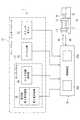
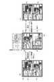
本実施の形態における射出成形機1は、成形機本体10と、成形機本体10の動作を制御する制御装置20とを備えている。射出成形機1は、制御装置20が備える表示部29の表示の仕方に特徴を有している。なお、本実施形態は油圧アクチュエータ(油圧機構)により駆動される射出成形機1を用いて説明するが、油圧アクチュエータに代えてサーボモータ、インバータモータ、IPM(Interior Permanent Magnet)モータなどの電動モータによる電動アクチュエータを適用した射出成形機1としても支障ない。
成形機本体10は、型締ユニット11と、可塑化ユニット15と、を備える。
型締ユニット11は、図示を省略する固定金型が取り付けられた固定ダイプレート12と、図示を省略する可動金型が取り付けられた可動ダイプレート13とを備えている。型締ユニット11は、可動ダイプレート13を固定ダイプレート12に向けて移動させる油圧機構を備えており、射出成形に先立って、可動ダイプレート13を移動させて可動金型を固定金型に当接させる。そしてさらに、油圧機構の作動油の圧力を高めて、可動金型と固定金型を締め付けて、型締めを行った後に、可動金型と固定金型の間に形成されるキャビティに、可塑化ユニット15から溶融樹脂を射出して成形品を得る。Hereinafter, the present invention will be described in detail based on embodiments shown in the accompanying drawings.
The
The
The
可塑化ユニット15は、型締ユニット11の側である前方側に吐出ノズルが形成された加熱シリンダ16と、加熱シリンダ16の内部に設けられた図示を省略するスクリュとを備えている。可塑化ユニット15は、スクリュを前進又は後退させる駆動源と、スクリュを正転又は逆転させる駆動源と、樹脂原料を加熱シリンダ16の内部に供給するための原料ホッパなどの図示を省略する構成も備えている。
可塑化ユニット15では、スクリュが回転されると、原料ホッパから供給された例えばペレット状の熱可塑性樹脂が、加熱シリンダ16の前方側へ搬送される。この搬送過程において、この樹脂ペレットは徐々に加熱、溶融して、スクリュの前方に貯留される。貯留により発生する樹脂の圧力を受けてスクリュは原料ホッパ側に後退しながら所定量の溶融樹脂をスクリュの前方に計量する。その後、吐出ノズルから、計量された溶融樹脂が型締ユニット11の固定金型と可動金型の間に形成されるキャビティへ所定量だけ射出される。The
In the
以上の要素を備える射出成形機1を用いて成形品を得るために、以下の各工程が順に実行される。すなわち、可動金型と固定金型を閉じて高圧で型締めする型締工程と、樹脂ペレットを加熱シリンダ16の内部で加熱、溶融して可塑化させる可塑化工程と、可塑化された溶融樹脂を、可動金型と固定金型の間に形成されるキャビティに射出、充填する射出工程と、キャビティに充填された溶融樹脂が固化するまで冷却する冷却工程と、金型を開放する型開き工程と、キャビティ内で冷却固化された成形品を取り出す取り出し工程と、を経て成形品が得られる。 In order to obtain a molded product using the
成形機本体10は、型締ユニット11及び可塑化ユニット15に各種のセンサを備えており、以上の各工程を実行している間にセンサで得られたセンシング情報SRは、制御装置20に送信される。センシング情報SRとしては、例えば、型締め圧力、射出圧力などがある。 The molding machine
制御装置20は、成形機本体10から送られるセンシング情報SRを用い、あるいは、制御装置20が予め備える情報を用いて、成形機本体10が型締工程、可塑化工程、射出工程…の各工程に必要な動作を行うように、動作指令情報OCを生成するとともに、成形機本体10の各駆動部に向けて動作指令情報OCを送信する。成形機本体10の各駆動部は、受信した動作指令情報OCに基づいて射出成形を行うのに必要な動作を実行する。
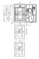
制御装置20は、処理部20aと記憶部20b(制御部)を備えており、処理部20aは作業者からの指示、選択にしたがって、記憶部20bに記憶されている種々の情報を読み出して表示部29に表示させる。The
The
動作指令情報OCは、射出成形機1を操作する作業者が制御装置20に入力する種々の設定値、動作の選択、表示画像の選択などの情報に基づいて、制御装置20にて生成される。なお、ここでいう「入力」は、メニューから特定の情報を選択する行為を含んでいる。
制御装置20は、マン・マシン・インターフェース21を備えており、作業員はマン・マシン・インターフェース21を介して制御装置20に種々の情報を入力する。マン・マシン・インターフェース21は、各種スイッチボタン23と、ソフトキーおよびハードキー入力部25と、タッチパネル27とを備える。The operation command information OC is generated by the
The
スイッチボタン23は、制御装置20の電源のオン・オフを行うスイッチ、成形機本体10の電源のオン・オフを行うスイッチ、装置の移動および移動方向の選択を行うなどの可倒式スイッチ、スイッチのオン・オフによりランプが点灯あるいは点滅あるいは消灯するスイッチなど各種のスイッチがある。
またスイッチボタン23は、成形機本体10の各種動作に対応して設けることもできる。例えば、型締め工程に対応するスイッチボタン23、射出工程に対応するスイッチボタン23などを設けることができる。この場合のスイッチボタン23はメニューボタンを含む構成としてもよい。The
The
キー入力部25は、前述した各工程の選択、選択された工程を実行する上で必要な設定値の入力、あるいは、表示部29に表示させる情報の選択を行う。アルファベットに対応するキー、0〜9の数値に対応するテンキーを含む、コンピュータ装置に付随するキーボードをキー入力部25として用いることができるし、タッチパネル上に展開したキーボードをキー入力部25として用いることもできる。キー入力部25から入力された情報は、制御装置20に送られる。 The
タッチパネル27は、タッチ情報検知部28(以下、検知部28という)と表示部29を備えており、表示部29の表面を押す(タッチする)と、検知部28がタッチされた領域の位置を特定するとともに、タッチされた領域に対応する操作ができるようにされた、表示装置と入力の機能を併せ持つ機器である。 The
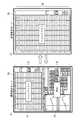
表示部29は、図2に示すように、縦長の全表示領域30を備えており、全表示領域30に一つのまとまった情報(単一の表示画像)を表示させることができる。また、表示部29は、異なる2つの表示画像を、各々、全表示領域30を縦方向に2等分にした第1表示領域31と第2表示領域32に表示させることができる。このように、表示部29は、第1表示領域31と第2表示領域32の各々に異なる単一の表示画像を表示させる標準表示モードと、全表示領域30を用いて単一の表示画像を表示させる拡張表示モードと、を備えている。表示部29は、標準表示モードと拡張表示モードを選択的に切り替えて表示画像を表示させることができる。図2は標準表示モードの例を示しているが、本実施形態の制御装置20は、標準表示モードがデフォルトとして設定されている。ただし、全ての表示画像のデフォルトを標準表示モードとせず、各表示画像毎のデフォルト表示を標準表示モードまたは拡張表示モードに選択設定してもよい。例えば型締め工程、射出工程、可塑化工程などの設定画面のデフォルトを標準表示モードとし、トレンドリストなどのデータ表示画面のデフォルトを拡張表示モードとしてもよい。
表示部29は、表示画像を選択するための図12、図13に示すようなメニューボタンを表示させることができる。例えば、射出工程の設定画像を選択するためのボタン、型締め工程の設定画像を選択するためのボタンなどを表示させ、作業者が選択できるようにする。メニューボタンは例えば、図12に示すような、カテゴリー名による第1選択ボタンリストL1の中から任意のボタン(Temp)をタッチして選択すると、カテゴリー毎の各表示画像を選択できる第2選択ボタンリストL2を表示する2段階式のメニューボタンでもよい。この場合、図12のように第1選択ボタンリストL1の上方に第2選択ボタンリストL2を表示してもよいし、第2選択ボタンリストL2を第1選択ボタンリストL1と同じ位置に上書き表示してもよい。また、図13に示すような、全カテゴリーC1と各カテゴリー毎の表示画像C2を一覧できるメニューボタンとしてもよい。メニューボタンの階層は2階層に限らず3階層以上であってもよい。
また、図13の最下層に示すような、作業者毎のメニューボタンにカスタマイズとしてもよい(C3参照)。この場合、予め作業者毎にIDを与え、このID毎に制御装置に記憶領域を割り付けて、作業者が好んで使う操作画面群の表示選択ボタンをまとめたメニューボタンを作業者のID毎にそれぞれ記憶し、呼び出し表示できるようにすることが好ましい。一般に成形条件を作成する作業者には独自の成形条件選定ノウハウがあり、各作業者毎に好んで使用する操作画面が異なる。よって、各作業者毎にメニューボタンをカスタマイズすることによって、選択画面のメニュー表示項目を少数に絞り込むことで作業者の表示画面のボタン位置認識およびボタン選択作業時間を短縮し作業効率を向上させるのに有効である。また各作業者毎にメニューボタンをカスタマイズする処理を自動で行ってもよい。具体的には、各作業者それぞれが頻繁に使用する設定画面を制御装置20が学習して、各ID毎にメニューボタンを自動で選定し、メニューボタンをカスタマイズして記憶部20bに記憶させてもよい。またカスタマイズしたメニューボタンは、各ID毎に固有ではなく、所定の複数のIDにおいて共有するようにしてもよい。この場合、更に共有のパスワードを設けてもよいし、各ID毎のパスワードをグループとして管理しメニューボタンの共用を可能としてもよい。また記憶部20bに記憶したカスタマイズしたメニューボタンを呼び出し、追加または削除などの編集を可能とすることが好ましい。この場合、編集が可能な作業者は、該メニューボタンを共有可能なIDをもつ作業者全員としても、予め編集可能者として登録されているIDの所有者のみに限定してもよいが、セキュリティー上においては予め編集可能者として登録されているIDの所有者のみに限定しておくことが好ましい。
また金型あるいは対象成形品毎にその操作画面の表示選択ボタンをまとめたメニューボタンをそれぞれ記憶し、呼び出し表示できるようにすることが好ましい。一般に各金型または成形品毎に良品成形に影響する度合いの大きい成形機の運転パラメータが異なる。よって、各金型または成形品毎に影響の大きいパラメータを備えた設定画面にメニューボタンをカスタマイズして、選択画面のメニュー表示項目を少数に絞り込むことによって、作業者の表示画面の選択時間を短縮し作業効率を向上させるのに有効である。
更に、同じIDでも複数のメニューボタンを記憶できるようにすることが好ましい。この場合、所定の金型または成形品の成形条件を制御装置20に読み込ませた後、作業者のIDを制御装置20が認識すると、制御装置20が作業者のIDと金型または成形品の管理番号と照合して、該作業者が該金型または該成形品に対して主に使用する操作画面のメニューリストを記憶部20bから読み出して表示部29に表示できるように準備する。もちろん、制御装置20による作業者のIDの認識後に所定の金型または成形品の成形条件を制御装置20に読み込ませた場合も同様である。これによると成形品が異なると作業者毎に作業効率のよい好ましい操作画面も異なる場合などにおいて、各作業者が独自に成形条件を選定しやすく、それぞれの対象成形品毎の好ましいと思っている操作画面のメニューボタンをいつでも記憶部20bから呼び出すことができて作業性が向上できる。
また記憶部20bに既に登録した操作画面のID毎または金型あるいは製品の管理番号毎のメニューボタンを読み出し後に編集し、編集後のメニューボタンを記憶部20bに更新記憶できるようにすることが好ましい。この場合、作業者がより使いやすいように改善したときは、常に最新の操作画面のメニューボタンを呼び出せるので作業性向上に有効である。
またカスタマイズしたメニューボタンの記憶部20bは、射出成形機1の制御装置20に設けてもよいし、複数の射出成形機を集中管理する図示しない集中管理装置に設けても良い。記憶部20bを集中管理装置に設ける場合は、作業者は集中管理装置により管理されているどの射出成形機を用いた場合でも、自己のカスタマイズしたメニューボタンを使用できるので、一々射出成形機毎にメニューボタンをカスタマイズし記憶部に記憶させる処理を行う必要が無く、作業効率が向上する。
またカスタマイズしたメニューボタンの記憶部20bは、射出成形機1の制御装置20に設けた場合においても、複数の射出成形機の制御装置同士が通信により連携して互いの記憶装置からカスタマイズしたメニューボタンを呼び出して共有してもよい。具体的には作業者のIDを認識した射出成形機の制御装置(仮に制御装置Aとする)が、この作業者がカスタマイズしたメニューボタンを記憶している他の射出成形機の制御装置(仮に制御装置Bとする)を検索して探し出す。制御装置Aが制御装置Bから、この作業者のIDに関連したメニューボタンを通信により受け取って、制御装置Aの表示装置にメニューボタンを表示してもよい。As shown in FIG. 2, the
The
Moreover, it is good also as customization to the menu button for every operator as shown in the lowest layer of FIG. 13 (refer C3). In this case, an ID is assigned to each worker in advance, a storage area is allocated to the control device for each ID, and a menu button that summarizes display selection buttons of operation screen groups that the operator preferably uses is assigned to each worker ID. It is preferable to store each of them so that they can be called and displayed. In general, workers who create molding conditions have their own molding condition selection know-how, and the operation screens that are preferably used are different for each worker. Therefore, by customizing the menu button for each worker, the menu display items on the selection screen are narrowed down to a small number, so that the button position recognition and button selection work time on the worker's display screen can be shortened and work efficiency can be improved. It is effective for. Further, the process of customizing the menu button for each worker may be automatically performed. Specifically, the
In addition, it is preferable that menu buttons each including a display selection button on the operation screen are stored for each mold or target molded product, and can be called and displayed. In general, the operating parameters of a molding machine having a large degree of influence on good product molding are different for each mold or molded product. Therefore, by customizing the menu button on the setting screen with parameters that have a large influence on each mold or molded product, and narrowing down the menu display items on the selection screen, the selection time of the operator's display screen is reduced. This is effective in improving work efficiency.
Furthermore, it is preferable that a plurality of menu buttons can be stored with the same ID. In this case, after the
Further, it is preferable that the menu button for each operation screen ID or die or product management number already registered in the
Further, the customized menu
In addition, even when the customized menu
表示部29は、自身に表示させるメニューボタン、キー入力部25等からの入力(選択)に応じた画像を表示させる。この表示画像に関する情報は、制御装置20の記憶部20b(以下、データ記憶部20bということがある)に保持されており、作業者の選択に応じてデータ記憶部20bから読み出され、表示部29に表示される。例えば、図2は、第1表示領域31に射出工程の設定画像が表示され、第2表示領域32に可塑化工程の設定画像が表示されている。選択された設定画像は、選択および表示履歴を消去する指示がない限り、記憶部20bに表示履歴として記憶される。設定画像に限らず、後述するトレンドデータなどの記憶部20bから読み出された情報は、記憶部20bに表示履歴として記憶される。 The
表示される表示画像が2つあるものとすると、表示部29は、表示させることが先に要求された表示画像を第1表示領域31に、表示させることが後に要求された表示画像を第2表示領域32に表示する。つまり、本実施形態においては、表示履歴の旧い表示画像が上側に位置する第1表示領域31に表示され、表示履歴の新しい表示画像が下側に位置する第2表示領域32に表示されるものとする。ただし、これとは上下を逆に表示させることもできる。例えば、仮に射出工程の設定画像しか読み出されていない段階では、第1表示領域31は空白の画面となるものとする。また、デフォルト画像を予め設定しておき、電源投入後の初期画面として、表示部29の第1表示領域31および第2表示領域32に自動でデフォルト画像を表示させてもよい。ここで簡単のために初期画面として第1表示領域31は空白の画面である場合で説明するが、例えば、可塑化工程の設定画像が読み出されると、空白であった第1表示領域31に射出工程の設定画像が表示され、第2表示領域32には可塑化工程の設定画像が表示される。あるいは、射出工程の設定画像しか読み出されていない段階で射出工程の設定画像を第1表示領域31に表示し、第2表示領域32を空白の画面としてもよい。この場合、例えば、可塑化工程の設定画像が読み出されると、第1表示領域31に射出工程の設定画像が表示されたままで、空白であった第2表示領域32には可塑化工程の設定画像が表示される。 Assuming that there are two display images to be displayed, the
射出工程の設定画像は、階層化されており、図2の第1表示領域31に示される設定画像は最上位に該当し、図2には示されていない、下位に位置する設定画像が存在している。この下位に位置する設定画像も、メニューボタンからの入力、選択に応じてデータ記憶部20bから読み出され、表示部29に表示される。この下位に位置する設定画像は第2表示領域32に表示させてもよいが、特に最上位の表示画像に対して下位に位置する表示画像が読み出されたときの、表示部29への別の表示の仕方については、後述する。ここでは、射出工程の設定画像について階層化されていることを説明したが、型締工程、可塑化工程、その他の工程の中に、設定画像が階層化されているものもある。階層化の数は任意であり、各工程に対応して2以上の任意の階層を構成することができる。下位の階層を有しない工程もあり得る。 The setting image of the injection process is hierarchized, and the setting image shown in the
本実施形態の表示部29は、第1表示領域31と第2表示領域32の各々に異なる表示画像を表示させる標準表示モードを備えているが、第1表示領域31に表示される画像情報(以下、第1表示画像P1ということがある)と第2表示領域32に表示される画像情報(以下、第2表示画像P2ということがある)を、相対的な位置関係を維持したままで同期してスクロールさせることができる。以下、図2及び図3を参照して、本実施形態の特徴である同期スクロールを説明する。なお、本実施形態でいうスクロールとは、記憶部20bに記憶した複数の画像情報の表示履歴をその順に表示装置に切り換えて表示させることを意味する。そして、その表示方法は作業者の操作によるスクロール指示により、表示装置に表示されている画像を一方向(典型的には、垂直または水平)にスライドさせる、つまり連続的に移動するように表示するという公知の手法を含む。また、画像をスライドさせる動的表示を行わずに、表示している画像を表示領域、例えば第1表示領域から一旦は消去してから隣接する第2表示領域に表示するという静的な切換表示の公知の手法をも含む。 The
[同期スクロール機能(図2,図3)]
図2に示すように標準表示モードで第1表示画像P1(例として、射出工程の設定画像)及び第2表示画像P2(例として、可塑化工程の設定画像)が表示されているものとする。なお、第1表示領域31には第1表示画像P1の全体が表示され、第2表示領域32には第2表示画像P2の全体が表示されている。なお、本実施形態においては第1表示領域31を表示部29の上方に、第2表示領域32を表示部29の下方に配置した例にて説明を進めるが、第1表示領域31を表示部29の下方に、第2表示領域32を表示部29の上方に配置してもよい。
例えば、キー入力部25に、表示されている画像をスクロールさせる指示が入力されると、図3(a)または図3(b)に示すように、第1表示画像P1と第2表示画像P2は、両者の相対的な位置関係を維持したままで同期してスクロールされる。スクロールは、スクロールの指示にしたがって、図3(a)に示すように、縦長の表示部29の縦方向Yの上向きに行なうこともできるし、図3(b)に示すように、縦方向Yの下向きに行なうこともできる。また、スクロール速度は、パーソナルコンピュータ、スマートフォン、タブレット型コンピュータなどに用いられる公知のスクロール速度で支障ない。またスクロール速度を作業者の好みに合わせて速度値を設定できるようにしてもよい。またスクロールが表示画像をスライドするように動的に表示する場合は、スクロール操作を画面が切り替わる途中で止めるなどの作業者のスクロール停止指示により任意の位置にて、例えばスクロールの途中で各表示画像の上部あるいは下部の一部のみしか表示されていない状態でスクロールを停止して画像を表示させても良い。もちろん、スクロールが任意の位置で停止した状態でも設定入力を可能にすることは言うまでもない。
図3は、理解を容易にするために、表示部29における下側(図3(a))及び表示部29における上側(図3(b))を白抜きにしているが、射出工程の設定画像及び可塑化工程以外の設定画像(例えば、型締め工程とする)がすでに選択されているものとすれば、当該白抜き部分に型締め工程の設定画像が表示される。また、スクロールの向きを白抜きの矢印で示しており、以下も同様である。さらに、スクロールにより表示部29からはみ出した部分の画像は、輪郭線を破線により示しているが、もちろん現実には見ることはできない。[Synchronized scroll function (Figs. 2 and 3)]
As shown in FIG. 2, it is assumed that the first display image P1 (for example, the setting image for the injection process) and the second display image P2 (for example, the setting image for the plasticizing process) are displayed in the standard display mode. . The entire first display image P1 is displayed in the
For example, when an instruction to scroll the displayed image is input to the
In FIG. 3, for easy understanding, the lower side of the display unit 29 (FIG. 3A) and the upper side of the display unit 29 (FIG. 3B) are outlined. If a setting image other than the image and the plasticizing process (for example, the mold clamping process) is already selected, the setting image of the mold clamping process is displayed in the white portion. The scroll direction is indicated by a white arrow, and the same applies to the following. Furthermore, the image of the part that protrudes from the
本実施形態によると、第1表示領域31に表示される第1表示画像と第2表示領域32に表示される第2表示画像にスクロールの指示を与えると、上下に隣接する2つの表示画像が同期してあたかも連結したままで上下にスクロール表示させることができる。したがって本実施形態によると、現時点では表示されていない表示画像(前表示画像)を再度表示させたい場合には、スクロールの指示を行なうだけで前表示画像を表示させることができる。よって本実施形態によると、作業者の記憶に頼って前表示画像の名称を思い出す、あるいは、メニュー画面から前表示画像を改めて選択するという手間を省けるので、作業者の負担を軽減できる。 According to the present embodiment, when a scroll instruction is given to the first display image displayed in the
また、本実施形態は、操作履歴、画面選択履歴の順に各設定画像をスクロール表示できるので、「以前に表示させた」というあいまいな作業者の記憶があれば、階層を記憶していなくてもスクロールするだけで、現時点では表示されていない画像を表示させることができるので、操作時間の短縮、生産性向上が可能である。
さらに、表示部29を第1表示領域31と第2表示領域32に区分し、第1表示画像と第2表示画像を同時に表示させることで、異なる工程の設定画面を縮小した表示や部分的な表示ではなく全画面を表示してその画面中の全ての設定値を見ながら条件の入力ができるので、別工程ではあるが一連の機械動作において関連深い設定値を確認しながら、互いの設定値を入力、変更できる。これにより、1つの表示領域に1つの表示画像を表示させる方式とは異なり、表示画像をいちいち切り替えて確認する手間や、画像が縮小されて小さくて見にくい文字を判別する手間や、同設定画面の他の部分に切り替えて表示させる手間が不要であり、かつ記憶違いや勘違いによる入力ミスを防止できる。
さらに、第1表示領域31と第2表示領域32には選択された順序に表示画像が表示されるので、作業者が機械の運転条件の設定において、独自のノウハウで設定順序がある場合に、自分の効率のよい設定順序に従って、設定画像の配置を実現できる。よって、本実施形態によると、作業者毎の操作要領に表示順序をカスタマイズすることも可能である。この場合、予め作業者毎にIDを与え、このID毎に制御装置に記憶領域を割り付けて、操作画面の連結順序、レイアウトを作業者のID毎にそれぞれ記憶し、呼び出し表示できるようにすることが好ましい。また、金型あるいは対象成形品毎に操作画面の連結順序、レイアウトをそれぞれ記憶し、呼び出し表示できるようにすることが好ましい。更に、同じIDでも複数の操作画面の連結順序、レイアウトを記憶できるようにすると、対象成形品によって設定画面の作業効率のよい好ましいレイアウトが異なった場合などにおいて、それぞれの対象成形品毎の好ましい操作画面の連結順序、レイアウトをいつでも記憶部20bから呼び出すことができるようにすることが好ましい。
またレイアウトのカスタマイズ処理は、作業者が成形条件選定の際に実際に表示させた設定画像と表示履歴を、作業者による記憶部20bに記憶させる操作により行ってもよいし、カスタマイズ処理専用画面を設けて、作業者が該専用画面中において設定画面の選定とレイアウトの設定をしてカスタマイズを行い、記憶部20bに記憶させる操作によって行ってもよい。あるいは作業者が頻繁に使用する設定画像と表示順序を制御装置20が学習し、ID毎に自動でレイアウトを設定し記憶部20bに記憶してもよい。
また、記憶部20bに既に登録した操作画面の連結順序、レイアウトを読み出し後に編集し、編集後の操作画面の連結順序、レイアウトを記憶部20bに更新記憶できるようにすることが好ましい。この場合、作業者がより使いやすいように改善した場合に常に最新の操作画面の連結順序、レイアウトを呼び出せるので作業性向上に有効である。また記憶部20bに既に登録した操作画面のID毎または金型あるいは製品の管理番号毎のメニューボタンを読み出し後に編集し、読み出したメニューとは別のメニューとして保存できるようにしてもよいことは言うまでもない。
さらにまた、『○○前に表示させた』という作業者の記憶により、画面の表示順序を直感的に操作に反映することが可能なことから、作業者のイメージに沿った操作ができ、操作における作業者のストレスを低減できる。また、多数頁前に表示させた所望の画像をいち早く表示させるために、スクロール量を頁数などの数値で指定して所望の画像までジャンプさせて画像を切り替えてもよいし、予めスクロール速度を複数段に切り替えられるようにしておき、所望のスクロール速度を直接選択により切り替える或いは所定のタッチアクションにより自動で速度を切り替えてもよい。また、制御装置20に予めテキスト検索あるいはコード検索機能を備えておき、所望の画面のキーワードまたは該当コードを検索すると所望の画面を表示できるようにしてもよい。
スクロールの指示は、タッチパネル上のソフトスイッチあるいはシートキーなどのハードスイッチを押圧しての操作によるものでもよいし、タッチパネル上をタッチしながらスクロール方向に移動させるタッチアクション操作、いわゆるスワイプ操作によるものでもよい。あるいは作業者の音声によるスクロール方向指示を音声認識する方法でもよい。
また新しい設定画像を表示部29の上方から挿入しダウンスクロールすることで、より新しい設定画像を表示するようにするか、あるいは新しい設定画像を表示部29の下方から挿入しアップスクロールすることで、より新しい設定画像を表示するようにするかの切換は、作業者が自己が使い易い方を選択設定できるようにしてもよい。これにより作業者のイメージに合ったスクロール方向を選択できるので、つまりダウンスクロールにより履歴の新しい画像が見えるというイメージをもっている作業者でも、アップスクロールにより履歴の新しい画像が見えるというイメージをもっている作業者でも、どちらの作業者に対しても表示切り替えにより対応できるので、勘違いや違和感などの使い勝手の不都合を解消できる。Also, in the present embodiment, since each setting image can be scroll-displayed in the order of the operation history and the screen selection history, if there is an ambiguous worker's memory of “previously displayed”, the hierarchy may not be stored. By simply scrolling, an image that is not currently displayed can be displayed, so that operation time can be shortened and productivity can be improved.
Further, the
Further, since the display images are displayed in the selected order in the
Further, the layout customization process may be performed by an operation of storing the setting image and the display history actually displayed by the worker when selecting the molding conditions in the
In addition, it is preferable that the connection order and layout of the operation screens already registered in the
Furthermore, the operator's memory of “displayed before XX” allows the display order of the screen to be intuitively reflected in the operation, so that the operation according to the operator's image can be performed. The worker's stress can be reduced. Also, in order to quickly display a desired image displayed many pages before, the scroll amount may be specified by a numerical value such as the number of pages and jumped to the desired image, and the scroll speed may be changed in advance. The desired scroll speed may be switched by direct selection or the speed may be switched automatically by a predetermined touch action. Alternatively, the
The scrolling instruction may be performed by pressing a soft switch on the touch panel or a hard switch such as a sheet key, or by a touch action operation that moves in the scroll direction while touching the touch panel, that is, a so-called swipe operation. Good. Alternatively, a method of recognizing a scroll direction instruction by an operator's voice may be used.
In addition, a new setting image is inserted from above the
[標準表示と拡張表示の切り替え(図4)]
本実施形態は、前述のように標準表示モード及び拡張表示モードを備えているが、以下では図4を参照して、標準表示モードから拡張表示モードへの切り替え、または、その逆の効果的な利用形態を説明する。
図4(a)は、標準表示モードに従って第1表示画像P1と第2表示画像P2を、各々、第1表示領域31と第2表示領域32に表示させている。この例では、第2表示画像P2が射出工程の設定画像であり、第1表示画像P1が射出成形機1に関するトレンドリストを表している。このトレンドリストは、過去の射出成形で使用された条件の履歴を列挙したリスト形式のデータである。データとしては、例えば、射出のサイクル時間、可塑化時間、射出時間、射出開始位置などを含んでいる。作業者は、このデータを参照することにより射出成形機の動作の成形安定性や、特異な状態の有無や、それによる成形品の安定性、成形不良発生の可能性、成形機の異常などを評価することができる。よって作業者は安定した成形条件を設定するために、例えば射出工程の設定を行う際にこのデータを参照して第2表示画像P2に表示されている設定画像に対して、適正と思われる条件を入力することができる。[Switching between standard display and extended display (Fig. 4)]
Although the present embodiment includes the standard display mode and the extended display mode as described above, referring to FIG. 4 below, it is effective to switch from the standard display mode to the extended display mode or vice versa. A usage form will be described.
4A, the first display image P1 and the second display image P2 are displayed in the
トレンドデータは、過去の成形サイクルの運転データを各成形サイクル毎の履歴として列挙したものであり、数多くの成形サイクルを重ねてくると標準表示モードにおける第1表示領域31に収まりきれないデータ量となり、図4(a)においてはその部分は隠れている。作業者は、この隠れている部分の履歴データを参照したいこともある。そこで、本実施形態は、図4(b)に示すように、トレンドデータを、全表示領域30を使って表示させることができるようにしている。つまり、本実施形態は、標準表示モードで表示されていたトレンドデータを拡張表示モードに切り替えて表示させることができる。具体的には全表示領域30を使って表示させることによって、第1表示領域31のみで表示できるトレンドデータ数の2倍程度のトレンドデータ数を表示することができる。作業者は拡張表示モードで表示されているトレンドデータを参照して必要な射出工程の条件を抽出し、射出工程設定に役立てることができる。作業者は、条件の抽出を終えると、図4(a)に示すように、拡張表示モードから標準表示モードに復帰させてから、条件の入力を行なう。
上位の表示画像に対して下位の表示画像がある階層構成の表示画像群において、上位の表示画像が第1表示領域31あるいは第2表示領域32に表示されているものとする。この際に、当該上位の表示画像に対して拡張表示モードを指示した場合に、上位の表示画像を第1表示領域31に配置し、下位の表示画像を第2表示領域32に配置するような一対の表示画像を、階層構成の表示としてもよい。
また、逆に下位の表示画像が第1表示領域31あるいは第2表示領域32に表示されている際に、当該下位の表示画像に対して拡張表示モードを指示した場合に、上位の表示画像を第1表示領域31に配置し、下位の表示画像を第2表示領域32に配置するような一対の表示画像を、階層構成の表示としてもよい。Trend data is an enumeration of past molding cycle operation data as a history for each molding cycle. If a large number of molding cycles are repeated, the amount of data will not fit in the
It is assumed that the upper display image is displayed in the
Conversely, when the lower display image is displayed in the
標準表示モードから拡張表示モードへの切り替え、また、拡張表示モードから標準表示モードへの復帰(切り替え)は、作業者の指示に従う。この指示は任意であるが、例えば拡張表示モードにしたい画像が表示されている領域(本実施形態では、トレンドデータが表示されている第1表示領域31)をタッチする、キー入力部25から入力する、などが想定される。
また表示画像の誤表示を防止するために、拡張表示モードが使用可能な表示画像を、トレンドデータリストや制御信号リストなどのデータリストのみに限定してもよい。Switching from the standard display mode to the extended display mode and returning (switching) from the extended display mode to the standard display mode are performed according to instructions from the operator. This instruction is arbitrary, but for example, an input from the
Further, in order to prevent erroneous display of the display image, the display image that can be used in the extended display mode may be limited to only a data list such as a trend data list or a control signal list.
[新規選択画像情報の自動挿入・スクロール機能(図5)]
次に、本実施形態の他の特徴的な表示手法である、新規選択画像情報の自動挿入・スクロール機能について説明する。
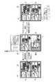
例えば、図5(a)に示すように、第1表示画像P1としての射出工程の設定画像が表示され、第2表示画像P2としての可塑化工程の主たる設定条件値が表示される可塑化主設定画像(以下、メイン設定画像)が表示されている状態で、第2表示画像P2よりも下位の階層の可塑化工程の周辺条件値の入力欄が配置されている可塑化副設定画像(以下、サブ設定画像)が選択されたものとする。なお、新たな設定画像は型締め工程などのサブ設定画像ではない設定画像でも良いが、本実施例では可塑化副設定画像を用いて説明する。
制御装置20は、図5(b)に示すように、サブ設定画像を第2表示領域32に表示させるとともに、それまで第2表示領域32に第2表示画像P2として表示されていたメイン設定画像は第1表示領域31に自動的に上方にスクロールされる。なお、本実施形態では表示履歴が旧い画像を表示部29の上方に、新しい画像を表示部29の下方に表示する例を示すが、表示履歴が旧い画像を表示部29の下方に、新しい画像を表示部29の上方に挿入し表示してもよい。メイン設定画像が第1表示画像P1となり、サブ設定画像が第2表示画像P2となる。同時に、それまで第1表示領域31に表示されていた第1表示画像P1としての射出工程の設定画像は、自動的に上方スクロールされることで、表示部29から姿を消し、表示が中断される。ただし、この射出工程の設定画像をメイン設定画像の上方に隣接して表示した表示履歴は記憶部20bに記憶されている。
作業者がサブ設定画像に対して必要な条件の入力を終えて、再度、当初の射出工程の設定画像とメイン設定画像を表示させたい場合には、作業者が指示することにより両画像は同期して下方にスクロールされ、図5(c)に示すように第1表示領域31と第2表示領域32に表示される。それまで表示されていたサブ設定画像は、下方にスクロールされることで表示部29からは姿を消すが、メイン設定画像の下方に隣接して表示した表示履歴は記憶部20bに記憶されている。
またこのとき、サブ設定画像が下方に姿を消した状態で、可塑化のメイン設定画像を見ながら新たな設定画像で設定作業を行いたい場合などで、例えば型締め工程の設定画像を選択して表示させた場合は、表示部29の上方に表示されている第1表示画像P1としてメイン設定画像を表示し、第2表示画像P2として型締め工程の設定画像が表示される。この場合、記憶部20bに記憶された表示履歴は、型締め工程の設定画像はメイン設定画像とサブ設定画像の間に挿入される。よって、第1表示画像P1としてメイン設定画像を表示し、第2表示画像P2として型締め工程の設定画像が表示されている状態で、作業者が上方へのスクロール操作を行えば、型締め工程の設定画面が第1表示画像P1として表示され、第2表示画像P2としてサブ設定画像が表示される。[Automatic insertion / scrolling function for newly selected image information (Fig. 5)]
Next, an automatic insertion / scroll function of newly selected image information, which is another characteristic display method of the present embodiment, will be described.
For example, as shown in FIG. 5 (a), an injection process setting image as the first display image P1 is displayed, and a main setting condition value of the plasticizing process as the second display image P2 is displayed. In the state where the setting image (hereinafter referred to as the main setting image) is displayed, the plasticizing sub-setting image (hereinafter referred to as the input field of the peripheral condition value of the plasticizing process in the lower hierarchy than the second display image P2 is arranged) , Sub-setting image) is selected. Note that the new setting image may be a setting image that is not a sub-setting image such as a mold clamping process, but in the present embodiment, description will be made using a plasticized sub-setting image.
As shown in FIG. 5B, the
When the operator finishes inputting necessary conditions for the sub setting image and wants to display the setting image of the initial injection process and the main setting image again, the images are synchronized by the operator's instruction. Then, it is scrolled downward and displayed in the
Also, at this time, if you want to perform setting work with a new setting image while looking at the main setting image for plasticization with the sub setting image disappearing downward, for example, select the setting image for the mold clamping process. When displayed, the main setting image is displayed as the first display image P1 displayed above the
本実施形態による新規選択画像の挿入手法によると、表示履歴中の任意の位置に新たに選択された設定画像をそれよりも上方に位置する設定画像に隣接して表示させるとともに、表示履歴として旧い設定画像を表示部29から自動的に排除できる。したがって、作業者がスクロールを指示する操作を行なうことなく、今、まさに表示させたい画像を同時に表示させて、迅速に条件の設定作業を行うことができるので、作業者の操作負担を軽減できる。
本実施形態による新規選択画像の挿入手法は、表示履歴の旧い表示画像が拡張表示モードで表示されている際に、新たな表示画像を表示させる要求がなされた場合にも適用することができ、新たな表示画像を拡張表示モードにより表示させるとともに、表示履歴の旧い表示画像(拡張表示モード)の表示を中断することができる。
また、表示履歴の旧い表示画像が拡張表示モードで表示されている際に、新たな表示画像を表示させる要求がなされると、表示履歴の旧い表示画像を標準表示モードで表示し直し、新たな表示画像を標準表示モードにより表示させるとともに、表示履歴の前後関係に従って新たな表示画像を表示履歴の旧い表示画像の上方あるいは下方に表示してもよい。
さらに、表示履歴の旧い表示画像が標準表示モードで表示されている際に、デフォルトの表示モードが拡張表示モードである新たな表示画像を表示させる要求がなされると、標準表示モードで表示されている表示履歴の旧い表示画像を上方あるいは下方にスライドアウトさせて、新たな表示画像を拡張表示モードにより表示してもよい。According to the method for inserting a newly selected image according to the present embodiment, the newly selected setting image is displayed at an arbitrary position in the display history adjacent to the setting image located above the setting image, and the display history is old. The setting image can be automatically excluded from the
The method of inserting a newly selected image according to the present embodiment can be applied to a case where a request for displaying a new display image is made when a display image with an old display history is displayed in the extended display mode. A new display image can be displayed in the extended display mode, and the display of the display image with the old display history (extended display mode) can be interrupted.
When a display image with an old display history is displayed in the extended display mode and a request for displaying a new display image is made, the display image with an old display history is displayed again in the standard display mode, and a new display image is displayed. The display image may be displayed in the standard display mode, and a new display image may be displayed above or below the old display image in the display history according to the context of the display history.
In addition, when a display image with an old display history is displayed in the standard display mode, if a request is made to display a new display image whose default display mode is the extended display mode, the display is displayed in the standard display mode. The old display image of the displayed display history may be slid out upward or downward, and a new display image may be displayed in the extended display mode.
[表示画像のスクロールロック機能(図6)]
本実施形態は、第1表示領域31に表示されている画像と第2表示領域32に表示されている画像が同期してスクロールされることを原則とするが、例外を設けている。この例外は、表示画像のスクロールロック機能である。この機能は、以下説明するように、トレンドリストや成形品によって異なる良品成形を行う成形条件として中心となる工程の動作設定を参照しながら、その他の良品成形に効果のある工程の条件を設定、入力する場合に有効である。[Scroll lock function for display image (Fig. 6)]
In the present embodiment, in principle, the image displayed in the
例えば、トレンドリスト画像、射出工程の設定画像及び可塑化工程の設定画像がすでに選択されており、図6(a)に示すように、第1表示領域31に第1表示画像P1としてトレンドリスト画像が表示され、第2表示領域32に第2表示画像P2として射出工程の設定画像が表示されているものとする。作業者は、トレンドリストを参照して射出工程の設定画像を当該画像に対して入力する。この入力が済んでから可塑化条件を入力しようとして、第2表示領域32に可塑化工程の設定画像を表示させようとすると、原則のままでは同期スクロールが機能してしまい、トレンドリストは表示部29から姿を消してしまう。これでは作業者にとって不都合であるから、本実施形態は、第1表示領域31に表示されているトレンドリスト画像がスクロールできないようにロックする機能を備える。なお、画像がスクロールできないようにロックする表示領域は表示部29の上方である第1表示領域31でも、下方である第2表示領域32でもどちらでもよいが、本実施形態では第1表示領域31に表示されている画像をロックするものとして説明する。 For example, a trend list image, a setting image for an injection process, and a setting image for a plasticizing process have already been selected. As shown in FIG. 6A, a trend list image is displayed as a first display image P1 in the
トレンドリスト画像がロックされた状態で、作業者がスクロールを指示する操作をしても、図6(b)に示すように、トレンドリスト画像が第1表示領域31に表示された状態が維持される。つまりロック処理がされた画像はロック機能が解除されるまでの間、常にロック処理がされた表示領域に固定表示される。一方、それまで第2表示領域32に表示されていた射出工程の表示画像と、隠れていた可塑化工程の設定画像はスクロールの指示が適用されることで、射出工程の表示画像は表示部29の上方に姿を消すとともに、可塑化工程の設定画像は第2表示領域32の下端からアップスライドするように表示される。このとき、射出工程の表示画像について、表示履歴として記憶されるのは、第1表示領域31に表示されるトレンドリスト画像をあたかも飛び越えるようにして、トレンドリストの上方に隣接している画像配置であったものである。つまり、このときの射出工程の画像は表示履歴上はトレンドリストの一つ以前に表示された画像として記憶されてもよい。よって、トレンドリストの画像ロックを解除した状態で、画面を下方にスクロール操作すると、射出工程の画像はトレンドリストの上方に隣接した配置にて上方から表示される。このスクロールのロック機能により作業者は、トレンドリスト画像を参照しながら、可塑化工程の設定画像に対して必要な条件を入力することができる。
また第1表示領域に第1表示画像が表示されており第2表示領域に第2表示画像が表示されており、第1表示画像または第2表示画像のいずれか一方がロック状態となっている際に、他方の表示画像をロック状態とするように作業者が操作した場合、今までロック状態となっていた一方の表示画像のロックを解除するようにしてもよい。具体的には、例えば、第1表示画像がロックされている状態で、第2表示画像をロック状態とするように操作された場合は、第2表示画像をロック状態とするとともに第1表示画像のロック状態を解除してもよい。
また第1表示画像と第2表示画像の両方をスクロールできないロック状態にすることもできる。この場合、例えば作業者のミスなどにより作業者の体の一部または作業者が把持している何らかの部材の一部などがスクロール操作部に当たり、意図しないスクロール動作が行われて画面が切り替わってしまうことを防止できる。またスクロールロックの解除を限られた作業者の予め設定されたIDに限定しても良い。Even when the operator performs an operation of instructing scrolling in a state where the trend list image is locked, the state where the trend list image is displayed in the
Further, the first display image is displayed in the first display area, the second display image is displayed in the second display area, and either the first display image or the second display image is in a locked state. At this time, when the operator operates to lock the other display image, the lock of the one display image that has been locked until now may be released. Specifically, for example, when the first display image is locked and the second display image is operated to be locked, the second display image is set to the locked state and the first display image is locked. The locked state may be released.
Also, it is possible to set a locked state in which both the first display image and the second display image cannot be scrolled. In this case, for example, a part of the operator's body or a part of some member held by the operator hits the scroll operation unit due to an operator's mistake or the like, and an unintended scrolling operation is performed and the screen is switched. Can be prevented. Further, the release of the scroll lock may be limited to a preset ID of a limited operator.
以上の通りであり、本実施形態は、スクロールのロック機能を備えることで、常にトレンドリストを直に参照しながら、射出工程と可塑化工程の2つの工程の条件を設定することができので、作業者の設定作業の負担を軽減することができる。なお、スクロールのロックが可能な画像はトレンドリストに限らず、その他の表示履歴中の任意の位置にレイアウトされた任意の画像に対して可能であり、任意の画像の一つがロックされた状態でスクロール可能なその他の画像も、射出工程と可塑化工程に限らず任意の画像がスクロール可能である。 As described above, this embodiment has a scroll lock function, so that it is possible to set conditions for two processes, an injection process and a plasticizing process, while always referring to the trend list directly. The burden of the operator's setting work can be reduced. Note that the images that can be scrolled are not limited to the trend list, but can be any other image laid out at any position in the display history, and one of the arbitrary images is locked. As for other scrollable images, any image can be scrolled without being limited to the injection process and the plasticizing process.
[前後画像情報の名称表示機能(図7)]
次に、表示部29に表示されていない前後画像情報の名称を表示する機能について、図7を参照して説明する。この機能は、作業者のあいまいな記憶を支援する。
例えば、図7に示すように、第1表示領域31にトレンドリスト画像が表示され、第2表示領域32に射出工程の設定画像が表示されているものとする。さらに、すでに2つの表示画像が選択されているが、一方の表示画像はトレンドリスト画像よりも表示履歴が旧く、トレンドリスト画像よりも上方に隠れており、他方の表示画像は射出工程の設定画像よりも表示履歴が新しく、射出工程の設定画像よりも下方に隠れているものとする。[Previous Image Information Name Display Function (FIG. 7)]
Next, a function for displaying names of front and rear image information not displayed on the
For example, as shown in FIG. 7, it is assumed that a trend list image is displayed in the
作業者は、トレンドリスト画像を参照しながら射出工程の設定画像に対して条件を入力していて少し時間が経過すると、履歴を忘れることもある。そこで、本実施形態は、いずれも現時点で表示されていない旧い表示履歴の画像情報と新しい表示履歴の画像情報を特定できる情報、例えば名称を表示させる。この例では、第1表示領域31に旧い表示履歴の画像情報として「型開閉」という名称を表示させるとともに、第2表示領域32に新しい表示履歴の画像情報として「可塑化」という名称を表示させる。名称を表示させる旧い表示履歴の画像情報は、第1表示領域31に表示されているトレンドリスト画像よりも1世代だけ旧いものである。また、名称を表示させる新しい表示履歴の画像情報は、第2表示領域32に表示されている射出工程の設定画像よりも1世代だけ新しいものである。また本実施形態では表示する画像の名称は1世代だけ旧いまたは1世代だけ新しい画像のみであるが、1世代以上の、例えば2世代、3世代などの複数世代旧いまたは新しい画像の名称を表示履歴順が分かるようにリスト表示させてもよい。この場合、最初から所定数の複数世代の画像の名称を全て表示してもよいが、最初は1世代前の画像の名称だけ表示し、所定の操作により所定数の複数世代の画像名称を表示するように複数段切換え式で表示することが、運転条件の設定入力部を表示するなど限られた表示領域を有効活用するうえで好ましい。 The operator may forget the history when a condition has been input for the injection process setting image while referring to the trend list image and a little time has passed. Therefore, in the present embodiment, information that can specify the image information of the old display history and the image information of the new display history that are not currently displayed is displayed, for example, names. In this example, the name “mold opening / closing” is displayed as the image information of the old display history in the
以上説明したように、前後画像情報の名称表示機能を備える制御装置20は、表示履歴中の任意の位置にレイアウトされた任意の画像において、現在表示されている画像より以前に表示された画像あるいは以後に表示された画像、具体的には本実施形態では「可塑化」の設定画像、または「型開閉」の設定画像を認知することができる。したがって、本実施形態によると、作業者の記憶があいまいになったとしても、スクロールして再表示させるのに、使い勝手がよい。 As described above, the
[表示画像の履歴消去機能(図8)]
本実施形態の制御装置20は、選択された表示画像を履歴として保持する。しかし、表示履歴の数が多くなると、作業者の負担が増えることもあり得る。そこで、制御装置20は、表示履歴中の任意の位置にレイアウトされた任意の表示画像を表示履歴から消去する機能を備えることができる。
例えば、図8(a)に示すように、第1表示画像P1としての射出工程の設定画像が表示され、第2表示画像P2としての可塑化工程の設定画像が表示されている状態で、第2表示画像P2に示されるよりも下位の階層の可塑化工程の設定画像(以下、サブ設定画像)が選択されたものとする。そうすると本実施形態の制御装置20は、図8(b)に示すように、サブ設定画像を第2表示領域32に表示させる。ここまでの動作は、前述した新規選択画像情報の自動挿入・スクロール機能(図5(a),(b))と同じである。[Display image history deletion function (Fig. 8)]
The
For example, as shown in FIG. 8A, in the state where the setting image of the injection process as the first display image P1 is displayed and the setting image of the plasticizing process as the second display image P2 is displayed, It is assumed that a setting image (hereinafter referred to as a sub-setting image) of a plasticizing process in a lower hierarchy than that shown in the two display image P2 is selected. Then, the
例えば、作業者がサブ設定画像Aに対して必要な条件の入力を終えてしまい、以後はサブ設定画像Aを表示させる必要がないと判断する場合がある。そして、可塑化工程について、他にサブ設定画像Bが存在する場合には、このサブ設定画像Bを新たに選択して表示履歴に登場させると、以後に不要なサブ設定画像Aが一々表示されて、作業者のスクロール作業効率の悪化を招くこともあるであろうし、必要のないサブ設定画像Aが存在すると、サブ設定画像Bを階層が上位の可塑化工程の設定画像に隣接して表示させることができなくなる。そこで、制御装置20は、作業者の指示にしたがって、必要のなくなった表示画像を記憶部20bに記憶した表示履歴から消去させる機能を備える。つまり、図8(b)に示すサブ設定画像に対して、消去スイッチにタッチする、あるいは消去のためのタッチアクションするなどの表示履歴からの消去を指示すると、自動でスクロールが実行されることで、図8(c)に示すように、サブ設定画像の選択前の表示に戻る。さらに、以後は、作業者が上向きのスクロールを指示しても、表示履歴が消去されていることから、表示が中止されたサブ設定画像は、表示部29に表示されることはない。 For example, the operator may finish inputting necessary conditions for the sub-setting image A, and may determine that it is not necessary to display the sub-setting image A thereafter. Then, if there is another sub-setting image B for the plasticizing process, when this sub-setting image B is newly selected and appears in the display history, unnecessary sub-setting images A are displayed one after another. If there is an unnecessary sub-setting image A, the sub-setting image B is displayed adjacent to the setting image of the higher-level plasticizing process. Can not be made. Therefore, the
以上説明したように、表示画像の履歴消去機能を備える制御装置20は、必要な画像情報のみを表示させることができるので、作業者は不必要な画像が表示されることでストレスを感じることがなく、操作性の高い射出成形機1が提供される。 As described above, since the
[第1領域と第2領域の入れ替え機能(図9)]
本実施形態の制御装置20は、表示履歴の旧い画像情報を第1表示領域31に表示させ、表示履歴の新しい画像情報を第2表示領域32に表示させるというルールにしたがっている。しかし、射出成形機1を操作する作業者が、例えば、第1表示領域31に射出工程の設定画像を表示させるとともに、第2表示領域32に可塑化工程の設定画像を表示させることを習慣としていることがある。ところが、当該作業者が、選択の順序を取り違えてしまい、第1表示領域31に可塑化工程の設定画像を表示させるとともに、第2表示領域32に射出工程の設定画像を表示させることもある(図9の右図)。[First and second area switching function (FIG. 9)]
The
作業者の習慣に従った画像の配置に変更するためには、可塑化工程の設定画像及び射出工程の設定画像の表示履歴を消した後に、射出工程の設定画像、可塑化工程の設定画像の順に選択をやり直しすればよい。しかし、これは作業者にとって負担となるため、制御装置20は、第1表示領域31に表示されている画像と第2表示領域32に表示されている表示履歴中に隣接してレイアウトされた任意の画像の入れ替えをする機能を備える。図9の左図は入れ替え後を示しているが、第1表示領域31に射出工程の設定画像が表示されるとともに、第2表示領域32に可塑化工程の設定画像が表示されており、作業者は習慣に則った作業を進めることができる。 In order to change the image layout according to the habits of the worker, after deleting the display history of the setting image of the plasticizing process and the setting image of the injection process, the setting image of the injection process, the setting image of the plasticizing process You only have to redo the selection in order. However, since this is a burden on the operator, the
画像の入れ替え機能を行なうための操作は任意であり、表示部29の中に画像入れ替えを指示するボタンを設ける、あるいは、キー入力部25の特定のキーにこの機能を指示するコマンドを割り当てることもできるし、所定のタッチアクションにより画面の入れ替え操作とすることもできる。 The operation for performing the image replacement function is arbitrary, and a button for instructing image replacement is provided in the
[横方向スクロール機能(図10,図11)]
本実施形態の制御装置20は、縦方向にスクロールすることを原則とするが、横方向のスクロールが必要、あるいは作業者の設定操作効率の向上に対して有効なこともある。そこで、制御装置20は、以下説明するように、表示履歴中の任意の位置にレイアウトされた任意の画像の横方向のスクロールを許容する。
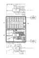
例えば、図10(a)に示すように、第1表示領域31に射出工程の設定画像が表示されるとともに、第2表示領域32に定数設定画像(1ページ目)が表示されている。定数設定画像は、射出工程を実行する上で必要な制御定数を設定するための画像である。必要な制御定数の数は極めて多く存在しており、第2表示領域32に一度に全てを表示させることは困難である。したがって、定数設定画像が3ページに分割されており、図10に示す例では、この3ページ分の定数設定画像がすでに選択されている。しかも、3ページ分の定数設定画像は、あらかじめ横方向Xに並んでいる。なお、第1表示領域31に定数設定画像を表示させ、第2表示領域32に射出工程の設定画像を表示させることもできる。[Horizontal scroll function (FIGS. 10 and 11)]
Although the
For example, as shown in FIG. 10A, an injection process setting image is displayed in the
作業者は、第2表示領域32に表示されている1ページ目の定数設定画像に対して必要な制御定数の入力を終えると、次の2ページ目の定数設定画像に対して必要な制御定数を入力するために、横方向Xへのスクロールを指示する。そうすると、図10(b)に示すように、2ページ目の定数設定画像が第2表示領域32に表示される。さらに、2ページ目の定数設定画像に必要な制御定数の入力を終えると、3ページ目の定数設定画像が第2表示領域32に表示されるように、横方向Xへのスクロールを指示すればよい。ここでは、図中、左向きへのスクロールを説明したが、3ページ分の制御定数の入力を終えた後の確認のために、右向きへのスクロールも指示にしたがって行うこともできる。
なお、1ページ目〜3ページ目の定数設定画像の左右の位置を逆にしてもよい。また、この左右の位置およびスクロール方向の切換は、ワンタッチのタッチ操作またはスイッチ操作によって行っても良い。When the operator finishes inputting the necessary control constants for the constant setting image of the first page displayed in the
The left and right positions of the constant setting images on the first page to the third page may be reversed. The left / right position and scroll direction may be switched by a one-touch touch operation or a switch operation.
このときのスクロールの指示の仕方は任意であり、第2表示領域32の表面を横方向Xになぞるスワイプ操作にすることができるし、キー入力部25に割り当てられたキーを操作することであってもよい。なお、図10に示すように、横方向Xに表示画像が並んでいる場合には、誤って、第1表示領域31に表示されている射出工程の設定画像までもが縦方向Yにスクロールされるのを避けるために、縦方向Yへのスクロールの指示を受け付けないようにし、スクロールの指示は横方向Xに制限してもよい。また横方向Xに表示画像が並んでいる場合に、横方向Xと縦方向Yの両方向に対してスクロール指示の待ち受け状態とし、縦方向Yにスクロール指示を行った場合に、横方向Xに並んだ設定画像のままスクロールさせてもよい。つまり第2表示領域に横方向Xに設定画像が並んだ状態で上方にスクロールを指示した場合、第2表示領域に表示されていた設定画像が第1表示領域に表示され、第1表示領域上にて横方向Xにスクロール可能としてもよい。
また第1表示領域31と第2表示領域32に表示されている両方の表示画像を、それぞれ独立に或いは同期して横方向Xにスクロールできるようにしてもよい。The method of instructing the scroll at this time is arbitrary, and can be a swipe operation in which the surface of the
Further, both display images displayed in the
本実施形態は、3ページ分の定数設定画像があらかじめ横方向Xに並んでいるが、これを実現する手法も任意である。例えば、3ページ分の定数設定画像が1つのまとまった情報として制御装置20に記憶しておき、定数設定画像がメニューにより選択されると、3ページに展開してから横方向Xに並べることができる。また、3ページ分の定数設定画像の情報を1ページ毎に制御装置20に記憶しておき、1ページ分のいずれかの画像情報を選択すると、他の2ページ分の画像情報も同時に選択するようにしておき、横方向Xに並べることもできる。後者の手法は、3ページの画像情報の間をリンクさせておくことになる。 In the present embodiment, the constant setting images for three pages are arranged in advance in the horizontal direction X, and a method for realizing this is also arbitrary. For example, constant setting images for three pages are stored in the
また、横方向Xに並べる画像は、定数設定画像に限るものではない。例えば、互いに関係の強い複数の工程の設定画像やデータリスト画像などを予め互いに関連づけて記憶部20bに記憶させる。そして、いずれかの画像が選択され表示された場合に、横方向Xにスクロール指示を行うとこの画像に関連づけられた画像が横方向Xにスクロール表示されてもよい。例えば、可塑化工程のメイン設定画面にサブ設定画面を関連づけておいて、メイン設定画面が表示された状態で横方向Xへのスクロール指示を行うとサブ設定画面を表示するようにしてもよい。また拡張表示モードで表示されたトレンドデータリストや制御信号リストなどの多量のデータリストを、拡張表示モードのままで横方向Xにスクロール表示させてもよい。また拡張表示モードのスイッチ操作で表示された表示画像が、階層構成の上位の表示画像と下位の表示画像からなる一対の表示画像である場合で、該上位であるメイン設定画像に対して複数の下位のサブ設定画像群が関連づけられている場合に、当該メイン設定画像を横方向Xにスクロール表示しないようにし、当該下位のサブ設定画像群のみ横方向Xにスクロールできるようにしてもよい。 Further, the images arranged in the horizontal direction X are not limited to the constant setting images. For example, setting images and data list images of a plurality of processes that are closely related to each other are stored in the
以上説明したように、横方向スクロール機能を備える制御装置20は、3ページ分の定数設定画像をスクロールするだけで、可塑化工程の設定画像を参照しながら、必要な制御定数を入力できるので、作業性に優れる。しかも、本実施形態によれば、各々のページの定数設定画像を個別にメニュー画面から選択することなく、3ページ分の定数設定画像を横方向Xに配列できるので、メニュー画面を単純化させることができる。 As described above, the
以上、本発明を実施形態に基づいて説明したが、本発明の主旨を逸脱しない限り、上記実施の形態で挙げた構成を取捨選択したり、他の構成に適宜変更することが可能である。
例えば、表示部29は縦長の表示領域を備えているが、本発明の表示手法は横長の表示領域を備える表示手段に適用することもできる。この場合、スクロールの同期は、横方向Xに沿って行なわれる。
また、本発明は、標準表示モード及び拡張表示モードを備えているが、これら以外の表示モードを備えることを妨げない。例えば、必要なときには、表示領域を4つに区分する表示の仕方を備えていてもよい。また表示画像を局部的に拡大表示するようにしてもよい。
さらに、本実施形態は、標準表示モードが表示領域を2等分にしているが、第1表示領域31と第2表示領域32の表示面積を異なるようにすることを妨げない。例えば、第1表示領域31の表示面積と第2表示領域32の表示面積の比を6:4というように区分することができるし、デフォルトとして2等分を採用しつつ、作業者からの指示に基づいて第1表示領域31と第2表示領域32の表示面積の比率を変えることもできる。
また、作業者が成形条件入力などの操作により、記憶部20bに記憶させた表示履歴を、作業者のIDを再び制御装置20に読み込ませる、あるいは表示履歴のリセット操作により、表示履歴を初期化するとともに、作業者のIDに関連づけて記憶部20bに記憶している操作画面の連結順序、レイアウトを再度読み出して、表示部29に表示してもよい。
また表示履歴上で2世代前に表示させた表示画像、例えば射出工程の設定画像をスクロールして再表示するのではなく、新たにメニューから再度、射出工程の設定画像を選択して表示させても良い。この場合、表示履歴上2世代前の射出工程の設定画像の表示履歴は消去するのが好ましい。
また制御装置20の電源をOFFした際に、表示履歴をリセットしてもよいし、あるいは電源OFFの直前の表示履歴を記憶部20bに記憶し、制御装置20が再度電源ONされた際には、記憶部20bに記憶しておいた電源OFFの直前の表示履歴を読み出して、表示部29に表示させてもよい。As described above, the present invention has been described based on the embodiment. However, the configuration described in the above embodiment may be selected or changed to another configuration as long as it does not depart from the gist of the present invention.
For example, the
Moreover, although this invention is equipped with standard display mode and extended display mode, it does not prevent having display modes other than these. For example, when necessary, a display method of dividing the display area into four may be provided. Further, the display image may be locally enlarged and displayed.
Furthermore, in the present embodiment, the standard display mode divides the display area into two equal parts, but it does not prevent the display areas of the
In addition, the display history stored in the
Also, instead of scrolling and redisplaying the display image displayed two generations ago on the display history, for example, the injection process setting image, the injection process setting image is again selected and displayed from the menu. Also good. In this case, it is preferable to delete the display history of the setting image of the injection process two generations before in the display history.
The display history may be reset when the power of the
1 射出成形機
10 成形機本体
11 型締ユニット
12 固定ダイプレート
13 可動ダイプレート
15 可塑化ユニット
16 加熱シリンダ
20 データ保持部
20 制御装置
21 マン・マシン・インターフェース
23 スイッチボタン
25 キー入力部
27 タッチパネル
28 検知部
29 表示部
30 全表示領域
31 第1表示領域
32 第2表示領域
OC 動作指令情報
SR センシング情報
P1 第1表示画像
P2 第2表示画像
X 横方向
Y 縦方向
DESCRIPTION OF
Claims (12)
Translated fromJapanese前記表示部への前記表示画像の表示を制御する制御部と、
前記表示画像を前記表示部に表示させた経時的順番と関連づけて表示履歴として記憶する記憶部と、を備え、
前記制御部は、
第1方向へのスクロールの指示を受けると、前記記憶部に記憶した前記表示画像の表示における前記経時的順番の前後関係を維持したままで、前記表示画像を前記表示部にスクロール表示させる、
ことを特徴とする射出成形機の制御装置。A display unit for displaying one or more display images including information on molding conditions of the injection molding machine;
A control unit that controls display of the display image on the display unit;
Thepre-Symbol Display image and a storage unit for storing a display history in association with the temporal order of displaying on the display unit,
Wherein,
When receiving an instruction of scrolling in the firstdirection, while maintaining the context of the temporal order of the display of the display image storedbefore term memory unit, scroll through previousSymbol Display image on the display unit Let
A control apparatus for an injection molding machine.
前記表示部を第1表示領域と第2表示領域に区分し、Dividing the display unit into a first display area and a second display area;
前記第1表示領域に第1表示画像を表示させ、かつ、前記第2表示領域に第2表示画像を表示させることが可能であるとともに、It is possible to display a first display image in the first display area and display a second display image in the second display area,
前記第1表示領域に表示された前記第1表示画像又は前記第2表示領域に示された前記第2表示画像の少なくとも一方の表示画像を、At least one display image of the first display image displayed in the first display region or the second display image displayed in the second display region;
前記記憶部に記憶した前記表示画像の表示における前記経時的順番の前後関係を維持したままで、前記表示部にスクロール表示させる、The display unit is scroll-displayed while maintaining the chronological order of the temporal order in displaying the display image stored in the storage unit.
ことを特徴とする請求項1に記載の射出成形機の制御装置。2. The control device for an injection molding machine according to claim 1, wherein:
前記表示部の全表示領域に前記単数の表示画像を表示させる拡張表示モードと、を備え、
前記標準表示モードにより表示されている、前記第1表示画像、及び、前記第2表示画像の一方が選択されると、選択された前記第1表示画像、及び、前記第2表示画像のいずれか一方が拡張表示モードにて表示される、
請求項2に記載の射出成形機の制御装置。And the standard display mode for displayingthe pluralityof Viewing imageby dividing the display unit into the second display area and the first display area,
And a extended display mode for displaying theViewing imagesofthe singular in the whole display area of the display unit,
When one of the first display image and the second display image displayed in the standard display mode is selected, one of the selected first display image and the second display image One is displayed in extended display mode,
The control device for an injection molding machine according to claim2 .
請求項3に記載の射出成形機の制御装置。The display history of one of the first display image and the second display image not selected is held in the storage unit,
The control apparatus of the injection molding machine of Claim3 .
前記第3表示画像を前記第2表示画像に隣接して表示させるとともに、前記第1表示画像の表示を中断する、
ことを特徴とする請求項2に記載の射出成形機の制御装置。When the first display image with the old display history and the second display image with the new display history are displayed, a request to display a new third display image is made.
Displaying the third display image adjacent to the second display image and interrupting the display of the first display image;
The control apparatus for an injection molding machine according to claim2 .
前記第3表示画像を表示させる要求の直前に前記拡張表示モードで表示されていた前記表示画像の表示を中断するとともに、前記第3表示画像を前記拡張表示モードにより表示させる、
或いは、
前記第3表示画像を表示させる要求の直前に前記拡張表示モードで表示されていた前記表示画像を前記標準モードで表示させるとともに、前記第3表示画像を前記標準表示モードにより、前記第3表示画像を表示させる要求の直前に前記拡張表示モードで表示されていた前記表示画像に隣接させて表示させる、
ことを特徴とする請求項3に記載の射出成形機の制御装置。When prior Symbol display image is displayed by the extended display mode, when a request to display a third display image new is made,
Interrupting the display of the display imagedisplayed in the extended display mode immediately before the request to display the third display image, and displaying the third display image in the extended display mode;
Or
Together to display the displayimage displayedimmediately before the request for displaying the third display image in the extended display mode in the normal mode, by the third display image said standard displaymode, the third display image To display adjacent to the display imagedisplayed in the extended display mode immediately before the request to display
The control apparatus for an injection molding machine according to claim3 .
選択された前記第1表示画像、及び、前記第2表示画像の少なくとも一方は、スクロールが行なわれないロック状態とされる、
請求項2に記載の射出成形機の制御装置。When the first display image and the second display image are displayed adjacent to each other on the display unit,
At least one of the selected first display image and the second display image is in a locked state in which scrolling is not performed.
The control device for an injection molding machine according to claim2 .
請求項1又は2に記載の射出成形機の制御装置。Information specifying the display image that is not displayed but remains in the display history is displayed on the display unit.
The control apparatus of the injection molding machine of Claim 1or 2 .
選択された前記第1表示画像、及び、前記第2表示画像の一方又は双方の表示を中止する、
請求項2に記載の射出成形機の制御装置。When the first display image and the second display image are displayed adjacent to each other on the display unit,
Stopping display of one or both of the selected first display image and the second display image;
The control device for an injection molding machine according to claim2 .
前記第1表示画像を前記第2表示領域に、前記第2表示画像を前記第1表示領域に、表示位置を入れ替える、
請求項2に記載の射出成形機の制御装置。When the first display image is displayed in the first display area and the second display image is displayed in the second display area, based on an instruction,
Switching the display position of the first display image to the second display region and the second display image to the first display region;
The control device for an injection molding machine according to claim2 .
前記第1表示領域、及び、前記第2表示領域の一方又は双方は、前記第1方向と直交する第2方向へのスクロールが許可される、
請求項2に記載の射出成形機の制御装置。When the first display image is displayed in the first display area and the second display image is displayed in the second display area,
One or both of the first display area and the second display area are allowed to scroll in a second direction orthogonal to the first direction.
The control device for an injection molding machine according to claim2 .
前記表示部への前記表示画像の表示を制御する制御部と、
前記複数の表示画像を前記表示部に表示させた経時的順番と関連づけて表示履歴として記憶する記憶部と、を備える射出成形機の制御装置における画像の表示方法であって、
前記制御部は、
前記表示部を第1表示領域と第2表示領域に区分し、
前記第1表示領域又は前記第2表示領域の少なくともいずれか一方に前記表示画像を表示させている際に、前記記憶部に記憶した前記表示画像の表示における経時的な前後関係を維持したままで、前記第1表示領域又は前記第2表示領域に表示された前記表示画像の少なくとも一方を、前記表示部にスクロール表示させる、
ことを特徴とする射出成形機の制御装置における画像表示方法。A display unitcapable of displaying the display image information about molding conditionsincluding multiple injection molding machine,
A control unit that controls display of the display image on the display unit;
An image display method in a control device of an injection molding machine, comprising: a storage unit that stores the plurality of display images as a display history in association with a temporal order displayed on the display unit,
The controller is
Dividing the display unitinto a first display areaand a second display area;
When the display image is displayed in at least one of the first display area and the second display area,the temporal relationship in the display of the display image stored in the storage unit is maintained. , At least oneof the display images displayed in the first display area or the second display area is scroll-displayed on the display unit,
An image display method in a control device for an injection molding machine.
Applications Claiming Priority (3)
| Application Number | Priority Date | Filing Date | Title |
|---|---|---|---|
| JP2013114953 | 2013-05-31 | ||
| JP2013114953 | 2013-05-31 | ||
| PCT/JP2013/006558WO2014192048A1 (en) | 2013-05-31 | 2013-11-07 | Control device for injection molding machine and screen display method |
Publications (2)
| Publication Number | Publication Date |
|---|---|
| JP6017029B2true JP6017029B2 (en) | 2016-10-26 |
| JPWO2014192048A1 JPWO2014192048A1 (en) | 2017-02-23 |
Family
ID=51988133
Family Applications (2)
| Application Number | Title | Priority Date | Filing Date |
|---|---|---|---|
| JP2015519504AActiveJP6017029B2 (en) | 2013-05-31 | 2013-11-07 | Control device for injection molding machine and screen display method |
| JP2015519505AActiveJP6049874B2 (en) | 2013-05-31 | 2013-11-07 | Control device for injection molding machine |
Family Applications After (1)
| Application Number | Title | Priority Date | Filing Date |
|---|---|---|---|
| JP2015519505AActiveJP6049874B2 (en) | 2013-05-31 | 2013-11-07 | Control device for injection molding machine |
Country Status (5)
| Country | Link |
|---|---|
| US (2) | US20160110032A1 (en) |
| EP (2) | EP3006183B1 (en) |
| JP (2) | JP6017029B2 (en) |
| CN (1) | CN105121126B (en) |
| WO (2) | WO2014192048A1 (en) |
Cited By (1)
| Publication number | Priority date | Publication date | Assignee | Title |
|---|---|---|---|---|
| US11436999B2 (en) | 2019-10-17 | 2022-09-06 | Fanuc Corporation | Display device for injection molding machine |
Families Citing this family (41)
| Publication number | Priority date | Publication date | Assignee | Title |
|---|---|---|---|---|
| JP6425444B2 (en)* | 2014-07-28 | 2018-11-21 | 株式会社ソディック | Injection molding machine and display control method executed by injection molding machine |
| JP6479387B2 (en)* | 2014-09-29 | 2019-03-06 | 東洋機械金属株式会社 | Operating method of molding machine |
| KR101685288B1 (en)* | 2015-05-11 | 2016-12-09 | 주식회사 카카오 | Method for controlling presentation of contents and user device for performing the method |
| JP6294268B2 (en)* | 2015-07-31 | 2018-03-14 | ファナック株式会社 | Abnormality diagnosis device for injection molding machine |
| JP6290835B2 (en)* | 2015-08-27 | 2018-03-07 | ファナック株式会社 | Numerical control device and machine learning device |
| US10232536B2 (en)* | 2015-12-21 | 2019-03-19 | Fanuc Corporation | Molding monitoring apparatus |
| CN105584015A (en)* | 2016-01-12 | 2016-05-18 | 重庆世纪精信实业(集团)有限公司 | Clasping tool adjusting system and method based on adjustable clasping tool |
| JP2017132229A (en)* | 2016-01-29 | 2017-08-03 | 住友重機械工業株式会社 | Injection molding system |
| JP2017151522A (en)* | 2016-02-22 | 2017-08-31 | 東洋機械金属株式会社 | Display operation device and molding machine |
| JP6412048B2 (en)* | 2016-04-13 | 2018-10-24 | ファナック株式会社 | Injection molding machine equipped with a display device |
| US10509544B2 (en)* | 2016-06-22 | 2019-12-17 | Casio Computer Co., Ltd. | Schedule management apparatus |
| JP6729166B2 (en)* | 2016-08-16 | 2020-07-22 | 富士ゼロックス株式会社 | Information processing device and program |
| JP6472860B1 (en)* | 2017-10-17 | 2019-02-20 | 東芝機械株式会社 | Injection molding machine |
| JP6577550B2 (en)* | 2017-10-23 | 2019-09-18 | ファナック株式会社 | Display control apparatus and display control method |
| EP3804951B1 (en)* | 2018-03-02 | 2022-11-09 | ENGEL AUSTRIA GmbH | Visualization device and evaluation device for a production line comprising at least one cyclically operating molding machine |
| JP6998814B2 (en)* | 2018-03-29 | 2022-01-18 | 住友重機械工業株式会社 | Injection molding machine control device and injection molding machine |
| US10936163B2 (en)* | 2018-07-17 | 2021-03-02 | Methodical Mind, Llc. | Graphical user interface system |
| JP6802229B2 (en)* | 2018-09-25 | 2020-12-16 | ファナック株式会社 | Display device and display system for injection molding machines |
| JP7215897B2 (en)* | 2018-12-25 | 2023-01-31 | ファナック株式会社 | Input support device for injection molding machine |
| JP6898296B2 (en)* | 2018-12-27 | 2021-07-07 | ファナック株式会社 | Display device for injection molding machine |
| JP7227020B2 (en)* | 2019-01-31 | 2023-02-21 | 住友重機械工業株式会社 | Injection molding machine |
| JP7307610B2 (en)* | 2019-07-01 | 2023-07-12 | 芝浦機械株式会社 | Molding machine and display device |
| JP2021068286A (en)* | 2019-10-25 | 2021-04-30 | 三菱重工業株式会社 | Display device, display system, display method and program |
| JP7331081B2 (en)* | 2019-11-08 | 2023-08-22 | 株式会社日本製鋼所 | Injection molding machine, display method for injection molding machine, and display method for display device of injection molding machine |
| IL294364A (en) | 2019-12-27 | 2022-08-01 | Methodical Mind Llc | Graphical user interface system |
| WO2021150729A1 (en) | 2020-01-22 | 2021-07-29 | Methodical Mind, Llc. | Graphical user interface system |
| JP7395373B2 (en)* | 2020-01-31 | 2023-12-11 | 住友重機械工業株式会社 | Injection molding machine |
| JP7307206B2 (en)* | 2020-02-03 | 2023-07-11 | ファナック株式会社 | Molding condition display system, management device, injection molding machine, and molding condition display program storage medium |
| JP2021160149A (en)* | 2020-03-31 | 2021-10-11 | 住友重機械工業株式会社 | Injection molding machine, industrial machine |
| WO2022009828A1 (en)* | 2020-07-09 | 2022-01-13 | ファナック株式会社 | Injection molding management device |
| JP7553584B2 (en) | 2020-09-30 | 2024-09-18 | ファナック株式会社 | Data creation device and data creation system |
| CN112453351B (en)* | 2020-11-06 | 2022-03-08 | 中信戴卡股份有限公司 | Method and system for adjusting technological parameters of die casting machine and storage medium |
| EP4291381A4 (en)* | 2021-03-25 | 2025-01-15 | Barnes Group, Inc. | INJECTION MOLDING SYSTEM AND METHOD WITH TASK-BASED USER INTERFACE |
| JP2022181871A (en)* | 2021-05-27 | 2022-12-08 | セイコーエプソン株式会社 | Injection molding machine management system |
| JP7640016B2 (en)* | 2021-08-11 | 2025-03-05 | 住友重機械工業株式会社 | Injection molding machine control device, injection molding machine, and program |
| WO2024024079A1 (en)* | 2022-07-29 | 2024-02-01 | ファナック株式会社 | Display control device and display control method |
| US12436593B2 (en)* | 2022-09-06 | 2025-10-07 | Apple Inc. | Sensor-based display power control systems and methods |
| JP2025022411A (en)* | 2023-08-03 | 2025-02-14 | 東洋機械金属株式会社 | Data display device and molding machine |
| JP2025066856A (en)* | 2023-10-12 | 2025-04-24 | 株式会社日本製鋼所 | Injection Molding Machine |
| JP2025067627A (en)* | 2023-10-13 | 2025-04-24 | 株式会社日本製鋼所 | Information processing method, computer program, and information processing device |
| US12330360B1 (en)* | 2024-08-30 | 2025-06-17 | Sybridge Technologies U.S. Inc. | Attachable monitoring device for molding tools |
Citations (6)
| Publication number | Priority date | Publication date | Assignee | Title |
|---|---|---|---|---|
| JP2001145947A (en)* | 1999-11-19 | 2001-05-29 | Toshiba Mach Co Ltd | Display device of injection molding machine |
| JP2004082649A (en)* | 2002-08-29 | 2004-03-18 | Sumitomo Heavy Ind Ltd | Displaying device for injection-molding machine |
| JP2005231251A (en)* | 2004-02-20 | 2005-09-02 | Sumitomo Heavy Ind Ltd | Control method and control system of molding machine |
| JP2006297671A (en)* | 2005-04-18 | 2006-11-02 | Fanuc Ltd | Screen display control device of injection molding machine |
| JP2007196604A (en)* | 2006-01-30 | 2007-08-09 | Nissei Plastics Ind Co | Data display method and apparatus for molding machine |
| JP2013091183A (en)* | 2011-10-24 | 2013-05-16 | Nissei Plastics Ind Co | Display device for production machine |
Family Cites Families (23)
| Publication number | Priority date | Publication date | Assignee | Title |
|---|---|---|---|---|
| JP2871913B2 (en) | 1991-09-11 | 1999-03-17 | 東洋機械金属株式会社 | Injection molding machine operating condition setting method |
| DE4219259A1 (en)* | 1992-06-12 | 1993-12-16 | Karl Hehl | Process for controlling a plastic injection molding machine |
| JPH11115023A (en)* | 1997-10-09 | 1999-04-27 | Sumitomo Heavy Ind Ltd | Injection pressure detector of injection molding machine |
| JP3519604B2 (en) | 1998-05-28 | 2004-04-19 | ファナック株式会社 | Molding condition regeneration device for injection molding machine |
| US6684264B1 (en)* | 2000-06-16 | 2004-01-27 | Husky Injection Molding Systems, Ltd. | Method of simplifying machine operation |
| JP3739698B2 (en)* | 2001-12-19 | 2006-01-25 | 東洋機械金属株式会社 | Molding machine |
| JP3881612B2 (en)* | 2002-11-07 | 2007-02-14 | 日精樹脂工業株式会社 | Display device for injection molding machine |
| JP2006097671A (en) | 2004-09-02 | 2006-04-13 | Takamine Tsukamoto | Power generation method using waste cooking oil and waste lubricating oil as fuel, and device therefor |
| US7428709B2 (en)* | 2005-04-13 | 2008-09-23 | Apple Inc. | Multiple-panel scrolling |
| JP2006289911A (en)* | 2005-04-14 | 2006-10-26 | Toshiba Mach Co Ltd | Control device of injection molding machine |
| JP2007196390A (en)* | 2006-01-23 | 2007-08-09 | Sumitomo Heavy Ind Ltd | Controller for molding machine |
| KR100877829B1 (en)* | 2006-03-21 | 2009-01-12 | 엘지전자 주식회사 | A terminal having a scrolling function and a scrolling method thereof |
| JP4185149B2 (en)* | 2006-08-08 | 2008-11-26 | ファナック株式会社 | Injection molding machine |
| EP1886790B1 (en)* | 2006-08-08 | 2013-10-16 | Fanuc Corporation | Injection molding machine |
| JP5338466B2 (en)* | 2009-05-08 | 2013-11-13 | 株式会社リコー | Image forming apparatus, customization screen update method, and customization screen update program |
| JP2011041221A (en)* | 2009-08-18 | 2011-02-24 | Sony Corp | Display device and display method |
| JP5680349B2 (en)* | 2010-07-28 | 2015-03-04 | 株式会社日本製鋼所 | How to save and display operation history of injection molding machines |
| JP2011005870A (en)* | 2010-09-01 | 2011-01-13 | Toshiba Mach Co Ltd | Controller of injection molding machine |
| JP2012076427A (en)* | 2010-10-06 | 2012-04-19 | Japan Steel Works Ltd:The | Method of managing log-in history of injection molding machine, and the injection molding machine |
| JP5833822B2 (en)* | 2010-11-25 | 2015-12-16 | パナソニックIpマネジメント株式会社 | Electronics |
| JP2012168793A (en)* | 2011-02-15 | 2012-09-06 | Seiko Epson Corp | Image display device and control method of the same |
| JP5215489B2 (en)* | 2011-10-21 | 2013-06-19 | ファナック株式会社 | Injection molding machine management system |
| JP5861545B2 (en)* | 2012-03-30 | 2016-02-16 | 富士通株式会社 | Information processing apparatus, history control method, and history control program |
- 2013
- 2013-11-07JPJP2015519504Apatent/JP6017029B2/enactiveActive
- 2013-11-07USUS14/888,023patent/US20160110032A1/ennot_activeAbandoned
- 2013-11-07EPEP13885521.8Apatent/EP3006183B1/enactiveActive
- 2013-11-07WOPCT/JP2013/006558patent/WO2014192048A1/enactiveApplication Filing
- 2013-11-07CNCN201380075606.5Apatent/CN105121126B/enactiveActive
- 2013-11-07USUS14/787,131patent/US10338771B2/enactiveActive
- 2013-11-07EPEP13885772.7Apatent/EP3006184A4/ennot_activeWithdrawn
- 2013-11-07WOPCT/JP2013/006572patent/WO2014192049A1/enactiveApplication Filing
- 2013-11-07JPJP2015519505Apatent/JP6049874B2/enactiveActive
Patent Citations (6)
| Publication number | Priority date | Publication date | Assignee | Title |
|---|---|---|---|---|
| JP2001145947A (en)* | 1999-11-19 | 2001-05-29 | Toshiba Mach Co Ltd | Display device of injection molding machine |
| JP2004082649A (en)* | 2002-08-29 | 2004-03-18 | Sumitomo Heavy Ind Ltd | Displaying device for injection-molding machine |
| JP2005231251A (en)* | 2004-02-20 | 2005-09-02 | Sumitomo Heavy Ind Ltd | Control method and control system of molding machine |
| JP2006297671A (en)* | 2005-04-18 | 2006-11-02 | Fanuc Ltd | Screen display control device of injection molding machine |
| JP2007196604A (en)* | 2006-01-30 | 2007-08-09 | Nissei Plastics Ind Co | Data display method and apparatus for molding machine |
| JP2013091183A (en)* | 2011-10-24 | 2013-05-16 | Nissei Plastics Ind Co | Display device for production machine |
Cited By (1)
| Publication number | Priority date | Publication date | Assignee | Title |
|---|---|---|---|---|
| US11436999B2 (en) | 2019-10-17 | 2022-09-06 | Fanuc Corporation | Display device for injection molding machine |
Also Published As
| Publication number | Publication date |
|---|---|
| JP6049874B2 (en) | 2016-12-21 |
| EP3006183B1 (en) | 2018-05-30 |
| EP3006184A1 (en) | 2016-04-13 |
| WO2014192048A1 (en) | 2014-12-04 |
| JPWO2014192049A1 (en) | 2017-02-23 |
| JPWO2014192048A1 (en) | 2017-02-23 |
| CN105121125A (en) | 2015-12-02 |
| EP3006183A1 (en) | 2016-04-13 |
| US20160110032A1 (en) | 2016-04-21 |
| WO2014192049A1 (en) | 2014-12-04 |
| CN105121126A (en) | 2015-12-02 |
| US10338771B2 (en) | 2019-07-02 |
| EP3006184A4 (en) | 2017-04-05 |
| CN105121126B (en) | 2017-01-11 |
| EP3006183A4 (en) | 2017-01-25 |
| US20160082504A1 (en) | 2016-03-24 |
Similar Documents
| Publication | Publication Date | Title |
|---|---|---|
| JP6017029B2 (en) | Control device for injection molding machine and screen display method | |
| US5818450A (en) | Method of displaying data setting menu on touch input display provided with touch-sensitive panel and apparatus for carrying out the same method | |
| JP5421973B2 (en) | Production machine display | |
| JP6169483B2 (en) | Injection molding machine molding condition setting device | |
| KR102296354B1 (en) | Display operation terminal device, molding system, and computer program stored in the storage medium | |
| JP5654064B2 (en) | Display device and display method for injection molding machine | |
| JP6062267B2 (en) | Operating method of molding machine | |
| JP4977488B2 (en) | Injection molding machine | |
| JP5674867B2 (en) | Display device for injection molding machine | |
| WO2017179734A1 (en) | Display operation device, molding machine, and machine tool | |
| JP5485775B2 (en) | Method and apparatus for displaying input window on touch panel | |
| JP2015182087A (en) | Injection molding machine, and operation screen of injection molding machine | |
| CN105121125B (en) | The control device of injection (mo(u)lding) machine and picture display process | |
| JPH07241894A (en) | How to change the setting value of injection molding machine | |
| KR101326910B1 (en) | Injection Molding Machine and Sequence Control Method Thereof | |
| JP2017151522A (en) | Display operation device and molding machine | |
| JP3806393B2 (en) | Display device for injection molding machine | |
| JP2004155073A (en) | Display device of injection molding machine | |
| JP2024089198A (en) | Injection molding machine | |
| CN107206653B (en) | How to operate the molding machine | |
| JP2025066856A (en) | Injection Molding Machine | |
| JP2014148088A (en) | Screen for injection molder | |
| WO2022045005A1 (en) | Injection molding machine |
Legal Events
| Date | Code | Title | Description |
|---|---|---|---|
| TRDD | Decision of grant or rejection written | ||
| A01 | Written decision to grant a patent or to grant a registration (utility model) | Free format text:JAPANESE INTERMEDIATE CODE: A01 Effective date:20160830 | |
| A61 | First payment of annual fees (during grant procedure) | Free format text:JAPANESE INTERMEDIATE CODE: A61 Effective date:20160927 | |
| R150 | Certificate of patent or registration of utility model | Ref document number:6017029 Country of ref document:JP Free format text:JAPANESE INTERMEDIATE CODE: R150 | |
| S533 | Written request for registration of change of name | Free format text:JAPANESE INTERMEDIATE CODE: R313533 | |
| R350 | Written notification of registration of transfer | Free format text:JAPANESE INTERMEDIATE CODE: R350 | |
| R250 | Receipt of annual fees | Free format text:JAPANESE INTERMEDIATE CODE: R250 | |
| S111 | Request for change of ownership or part of ownership | Free format text:JAPANESE INTERMEDIATE CODE: R313111 | |
| R250 | Receipt of annual fees | Free format text:JAPANESE INTERMEDIATE CODE: R250 | |
| R350 | Written notification of registration of transfer | Free format text:JAPANESE INTERMEDIATE CODE: R350 | |
| R250 | Receipt of annual fees | Free format text:JAPANESE INTERMEDIATE CODE: R250 | |
| S533 | Written request for registration of change of name | Free format text:JAPANESE INTERMEDIATE CODE: R313533 | |
| R350 | Written notification of registration of transfer | Free format text:JAPANESE INTERMEDIATE CODE: R350 | |
| R250 | Receipt of annual fees | Free format text:JAPANESE INTERMEDIATE CODE: R250 | |
| R250 | Receipt of annual fees | Free format text:JAPANESE INTERMEDIATE CODE: R250 | |
| R250 | Receipt of annual fees | Free format text:JAPANESE INTERMEDIATE CODE: R250 | |
| R250 | Receipt of annual fees | Free format text:JAPANESE INTERMEDIATE CODE: R250 |