JP6014174B2 - CT image generation apparatus and CT image generation method - Google Patents
CT image generation apparatus and CT image generation methodDownload PDFInfo
- Publication number
- JP6014174B2 JP6014174B2JP2014560646AJP2014560646AJP6014174B2JP 6014174 B2JP6014174 B2JP 6014174B2JP 2014560646 AJP2014560646 AJP 2014560646AJP 2014560646 AJP2014560646 AJP 2014560646AJP 6014174 B2JP6014174 B2JP 6014174B2
- Authority
- JP
- Japan
- Prior art keywords
- detector
- projection
- image generation
- data
- backprojection
- Prior art date
- Legal status (The legal status is an assumption and is not a legal conclusion. Google has not performed a legal analysis and makes no representation as to the accuracy of the status listed.)
- Expired - Fee Related
Links
Images


Classifications
- A—HUMAN NECESSITIES
- A61—MEDICAL OR VETERINARY SCIENCE; HYGIENE
- A61B—DIAGNOSIS; SURGERY; IDENTIFICATION
- A61B6/00—Apparatus or devices for radiation diagnosis; Apparatus or devices for radiation diagnosis combined with radiation therapy equipment
- A61B6/52—Devices using data or image processing specially adapted for radiation diagnosis
- A61B6/5258—Devices using data or image processing specially adapted for radiation diagnosis involving detection or reduction of artifacts or noise
- A—HUMAN NECESSITIES
- A61—MEDICAL OR VETERINARY SCIENCE; HYGIENE
- A61B—DIAGNOSIS; SURGERY; IDENTIFICATION
- A61B6/00—Apparatus or devices for radiation diagnosis; Apparatus or devices for radiation diagnosis combined with radiation therapy equipment
- A61B6/02—Arrangements for diagnosis sequentially in different planes; Stereoscopic radiation diagnosis
- A61B6/03—Computed tomography [CT]
- A61B6/032—Transmission computed tomography [CT]
Landscapes
- Health & Medical Sciences (AREA)
- Life Sciences & Earth Sciences (AREA)
- Engineering & Computer Science (AREA)
- Medical Informatics (AREA)
- Pathology (AREA)
- Heart & Thoracic Surgery (AREA)
- High Energy & Nuclear Physics (AREA)
- Physics & Mathematics (AREA)
- Nuclear Medicine, Radiotherapy & Molecular Imaging (AREA)
- Optics & Photonics (AREA)
- Veterinary Medicine (AREA)
- Radiology & Medical Imaging (AREA)
- Biomedical Technology (AREA)
- Biophysics (AREA)
- Molecular Biology (AREA)
- Surgery (AREA)
- Animal Behavior & Ethology (AREA)
- General Health & Medical Sciences (AREA)
- Public Health (AREA)
- Computer Vision & Pattern Recognition (AREA)
- Pulmonology (AREA)
- Theoretical Computer Science (AREA)
- Apparatus For Radiation Diagnosis (AREA)
Description
Translated fromJapanese本発明はCT画像生成装置およびCT画像生成方法に関し、特に改良されたセパラブルフットプリント(Separable Footprint)法を用いたCT画像生成装置およびCT画像生成方法に関する。 The present invention relates to a CT image generation apparatus and a CT image generation method, and more particularly to a CT image generation apparatus and a CT image generation method using an improved separable footprint method.
X線コンピュータ断層撮影(CT)技術はすでに人体検査に広く使用されており、CT画像は疾病診断に対する根拠としてすでに30年の歴史があるが、CT画像再構成アルゴリズムを研究して放射線量を低減し、CT画質を改善し、画像アーティファクトを減少させることは、一貫して研究と臨床における重要な課題であった。 X-ray computed tomography (CT) technology is already widely used in human examinations, and CT images have a 30-year history as the basis for disease diagnosis. However, improving CT image quality and reducing image artifacts has been an important research and clinical challenge consistently.
実用において、CT画像再構成アルゴリズムには主に、フィルタ逆投影法と反復再構成アルゴリズムが含まれる。このうちフィルタ逆投影法は、CT画像再構成の慣用的な方法であり、従来のCT製品において広く応用されている。ただしフィルタ逆投影法では、画像を再構成する投影データにはノイズの干渉がないと仮定されているが、実際にはノイズは常に投影データに伴って存在し、特に低線量スキャンの場合は一層顕著であるため、高画質のCT画像を得ることが難しくなる。また臨床診療の発展に伴い、CTの臨床応用における範囲と深さは次第に従来にはなかった高いレベルに達しており、こうした新しい情勢の背景下で、業界ではCTの使用上の安全性の考慮ならびに画質に対して新たな高い要求が出現している。これによりフィルタ逆投影法は新しい需要を満たすことが困難になっている。 In practice, CT image reconstruction algorithms mainly include a filter back projection method and an iterative reconstruction algorithm. Among these, the filter back projection method is a conventional method of CT image reconstruction, and is widely applied in conventional CT products. However, in the filtered backprojection method, it is assumed that there is no noise interference in the projection data that reconstructs the image. However, in reality, noise always exists with the projection data, especially in the case of low-dose scanning. Since it is remarkable, it becomes difficult to obtain a high-quality CT image. In addition, with the development of clinical practice, the scope and depth of CT clinical application has gradually reached a high level that has not existed in the past. Under these new circumstances, the industry considers the safety of CT use. In addition, new high demands for image quality have emerged. This makes the filter backprojection method difficult to meet new demands.
上述の新たな需要に対し、ハイレベルの応用において、反復再構成アルゴリズムが重視され研究されている。反復再構成アルゴリズムは電子ノイズとその他の物理要素による画像アーティファクトを上手く処理することで、画質を保証しながら、検査時のX線量を低減することができる。ただしその膨大な計算量のために画像形成速度が遅延し、実際の臨床における応用ができなかった。しかし近年、コンピュータハードウェアおよび計算科学の急速な発展に伴い、反復再構成アルゴリズムが実際の製品に応用されることが可能となった。また社会の医療・健康への重視が増すにつれ、CT診断中のX線放射の人体健康に対する影響が益々注目されるようになり、X線の低放射線量化はすでにCT発展の潮流になっている。したがって、反復再構成アルゴリズムは次第に広く注視され、現在の研究の焦点になっている。同時に、中低レベルの応用では、フィルタ逆投影法において、アーティファクトを低減し、画質を向上する、新たな高精度の逆投影方法が研究されている。 In response to the new demands mentioned above, iterative reconstruction algorithms have been emphasized and studied in high-level applications. The iterative reconstruction algorithm successfully processes image artifacts due to electronic noise and other physical elements, thereby reducing the X-ray dose during the examination while ensuring image quality. However, due to the enormous amount of calculation, the image formation speed was delayed, and actual clinical application was not possible. However, in recent years, with the rapid development of computer hardware and computational science, iterative reconstruction algorithms can be applied to actual products. In addition, as the emphasis on medical care / health in society increases, the influence of X-ray radiation on human health during CT diagnosis has become more and more attention, and the reduction of X-ray radiation has already become a trend of CT development. . Therefore, iterative reconstruction algorithms are increasingly widely watched and are the focus of current research. At the same time, new high-accuracy backprojection methods that reduce artifacts and improve image quality are being studied in filtered backprojection methods for medium and low level applications.
反復再構成アルゴリズムには、主に多数回反復される投影と逆投影プロセスが含まれるが、従来のフィルタ逆投影アルゴリズムにおける主な手順は逆投影である。投影と逆投影方法には主に、従来の線束駆動型(Ray−Driven)や画素駆動型(Pixel−Driven)等によるものが含まれるが、モデル誤差が大きいため、反復再構成アルゴリズムにおける応用では、反復アルゴリズムを収束させることが難しくなる。そのため高精度の投影と逆投影方法が研究・提案され、最も典型的なものは近年提案された距離駆動型(Distance−Driven)とセパラブルフットプリント(Separable Footprint)の方法である(例えば特許文献1、特許文献2)。このうちセパラブルフットプリント法は、現時点で学界における最も優れた投影と逆投影モデルであるが、この方法も一種の近似法であり、一定のモデル誤差が依然として存在するため、モデル精度のさらなる改善・向上が期待されている。 The iterative reconstruction algorithm mainly includes a projection and backprojection process that is repeated many times, but the main procedure in the conventional filter backprojection algorithm is backprojection. Projection and backprojection methods mainly include those using the conventional line-drive type (Ray-Driven) or pixel-drive type (Pixel-Driven). However, since the model error is large, in the application in the iterative reconstruction algorithm, , It becomes difficult to converge the iterative algorithm. Therefore, highly accurate projection and backprojection methods have been researched and proposed, and the most typical ones are the recently proposed distance-driven and separable footprint methods (for example, patent literature). 1, Patent Document 2). Of these, the separable footprint method is currently the best projection and backprojection model in the academic world, but this method is also a kind of approximation method, and there is still a certain model error, which further improves model accuracy.・ Improvement is expected.
上述の背景を踏まえ、本発明は、セパラブルフットプリント法をベースに、アーティファクトを低減可能な、投影と逆投影の誤差をさらに減少させるCT画像生成装置およびCT画像生成方法を提供することを課題とする。 In light of the above-described background, the present invention provides a CT image generation apparatus and a CT image generation method capable of reducing artifacts and further reducing projection and backprojection errors based on the separable footprint method. And
本発明はセパラブルフットプリントアルゴリズムの加重係数をさらに修正することにより、加重係数(重み係数)の誤差を低減することを提案している。本発明は、主に投影と逆投影の精度要求が非常に高い反復再構成アルゴリズムに応用できるが、フィルタ逆投影アルゴリズムにも用いることができる。 The present invention proposes to reduce the error of the weighting factor (weighting factor) by further modifying the weighting factor of the separable footprint algorithm. Although the present invention can be applied mainly to an iterative reconstruction algorithm that requires very high accuracy in projection and backprojection, it can also be used in a filter backprojection algorithm.
すなわち本発明のCT画像生成装置は、X線源および検出器を備えて前記X線源と前記検出器の間に配置されたオブジェクトを検出するX線スキャナと、主処理器、重み付け算出ユニット、重み付けベクトル乗法ユニット、およびセパラブルフットプリント演算ユニットを含む処理器モジュールと、前記処理器モジュールで使用するパラメータを記憶する記憶モジュールと、を備え、前記重み付け算出ユニットは、前記記憶モジュールから幾何学パラメータを読み出し、前記幾何学パラメータに基き重み付けベクトルを算出し、前記主処理器は、前記幾何学パラメータを用いて投影/逆投影角度ループを制御し、前記重み付けベクトル乗法ユニットは、前記X線スキャナがスキャンした検出器データに前記重み付けベクトルを乗じることにより、補正された検出器値を算出し、前記セパラブルフットプリント演算ユニットは、前記補正された検出器値を用いて、セパラブルフットプリント投影・逆投影アルゴリズムを実行することを特徴とする。 That is, the CT image generation apparatus of the present invention includes an X-ray scanner that includes an X-ray source and a detector and detects an object disposed between the X-ray source and the detector, a main processor, a weighting calculation unit, A processor module including a weighted vector multiplication unit and a separable footprint calculation unit; and a storage module for storing parameters used in the processor module, wherein the weight calculation unit receives geometric parameters from the storage module. , And calculates a weighting vector based on the geometric parameter, the main processor controls a projection / backprojection angle loop using the geometric parameter, and the weight vector multiplication unit includes the X-ray scanner By multiplying the scanned detector data by the weighting vector. Calculates the corrected detector value, the separable flask footprint calculation unit, by using the corrected detector value, and executes a separable footprint projection-back projection algorithm.
また本発明のCT画像生成方法は、X線スキャナがスキャンしたデータを、検出器データとして記憶させるステップと、記憶モジュールに記憶された幾何学パラメータを用いて重み付けベクトルを算出するステップと、前記幾何学パラメータを用いて投影/逆投影角度ループを制御するステップと、前記検出器データに前記重み付けベクトルを乗じることにより、補正された検出器値を取得するステップと、前記補正された検出器値を用いて、セパラブルフットプリント投影・逆投影アルゴリズムを実行するステップと、を含むことを特徴とする。 The CT image generation method of the present invention includes a step of storing data scanned by an X-ray scanner as detector data, a step of calculating a weighting vector using a geometric parameter stored in a storage module, Controlling a projection / backprojection angle loop using a geometric parameter; obtaining a corrected detector value by multiplying the detector data by the weighting vector; and correcting the corrected detector value And performing a separable footprint projection / backprojection algorithm.
本発明のCT画像生成装置及びCT画像生成方法によれば、重み付けベクトル乗法ユニットにより検出器データに重み付けベクトルを乗じることにより、精度が向上した検出器値が取得される。この検出器値を用いて投影と逆投影を行うことにより、一般的なセパラブルフットプリント法を用いる装置と比較して、その投影と逆投影の誤差を低減し、アルゴリズムのモデリング精度を高めることができる。
これにより、反復再構成アルゴリズムの効率を向上させCT画像のアーティファクトを減少させることができる。According to the CT image generation apparatus and CT image generation method of the present invention, a detector value with improved accuracy is obtained by multiplying the detector data by the weight vector by the weight vector multiplication unit. By performing projection and backprojection using this detector value, the error of the projection and backprojection can be reduced and the modeling accuracy of the algorithm can be improved compared to a device using a general separable footprint method. Can do.
This can improve the efficiency of the iterative reconstruction algorithm and reduce CT image artifacts.
以下、本発明のCT画像生成装置とそれにより実現されるCT画像生成方法の実施形態を説明する。 Hereinafter, an embodiment of a CT image generation apparatus of the present invention and a CT image generation method realized thereby will be described.
本実施形態のCT画像生成装置は、X線源(302)および検出器(303)を備えて前記X線源と前記検出器の間に配置されたオブジェクトを検出するX線スキャナ(701)と、検出器データブロック(708)、重み付けデータブロック(709)、パラメータデータブロック(710)、および入力/出力結果画像データブロック(711)を含む記憶モジュール(705)と、主処理器(715)、重み付け算出ユニット(712)、重み付けベクトル乗法ユニット(713)、およびセパラブルフットプリント演算ユニット(714)を含む処理器モジュール(707)と、データインタフェースモジュール(702)と、ユーザインタフェースモジュール(704)とを備える。検出器データブロックは、X線スキャナがスキャンしたデータを、データインタフェースモジュールを介して取り込み検出器データとして記憶する。重み付け算出ユニット(712)は、パラメータデータブロックから幾何学パラメータを取得するとともに、この幾何学パラメータに基づいて重み付けベクトルを算出する。主処理器は、幾何学パラメータを用いて投影/逆投影角度ループを制御し、重み付けベクトル乗法ユニット(713)は、検出器データに重み付けベクトルを乗じることにより、補正された検出器値を取得する。セパラブルフットプリント演算ユニット(714)は、補正された検出器値を用いて、セパラブルフットプリント投影・逆投影アルゴリズムを実行する。 The CT image generation apparatus of the present embodiment includes an X-ray scanner (701) that includes an X-ray source (302) and a detector (303) and detects an object disposed between the X-ray source and the detector. A storage module (705) including a detector data block (708), a weighted data block (709), a parameter data block (710), and an input / output result image data block (711), a main processor (715), A processor module (707) including a weight calculation unit (712), a weight vector multiplication unit (713), and a separable footprint calculation unit (714), a data interface module (702), and a user interface module (704); Is provided. The detector data block captures data scanned by the X-ray scanner via the data interface module and stores it as detector data. The weight calculation unit (712) obtains a geometric parameter from the parameter data block and calculates a weight vector based on the geometric parameter. The main processor uses the geometric parameters to control the projection / backprojection angle loop, and the weighted vector multiplication unit (713) obtains the corrected detector value by multiplying the detector data by the weighted vector. . The separable footprint calculation unit (714) executes a separable footprint projection / backprojection algorithm using the corrected detector values.
また本実施形態のCT画像生成方法は、X線源および検出器を備えて前記X線源と前記検出器の間に配置されたオブジェクトを検出するX線スキャナと、検出器データブロック、重み付けデータブロック、パラメータデータブロック、および入力/出力結果画像データブロックを含む記憶モジュールと、主処理器、重み付け算出ユニット、重み付けベクトル乗法ユニット、およびセパラブルフットプリント演算ユニットを含む処理器モジュールと、データインタフェースモジュールと、ユーザインタフェースモジュールと、を備えたCT画像生成装置のCT画像生成方法であり、前記X線スキャナがスキャンしたデータを、検出器データとして前記データインタフェースモジュールを介して前記検出器データブロックに記憶させるステップと、前記重み付け算出ユニットが、前記パラメータデータブロックから幾何学パラメータを取得するとともに、この幾何学パラメータに基づいて重み付けベクトルを算出するステップと、前記主処理器が、前記幾何学パラメータを用いて投影/逆投影角度ループを制御するステップと、前記重み付けベクトル乗法ユニットが、前記検出器データに前記重み付けベクトルを乗じることにより、補正された検出器値を取得するステップと、前記セパラブルフットプリント演算ユニットが、前記補正された検出器値を用いて、セパラブルフットプリント投影・逆投影アルゴリズムを実行するステップと、を含む。 The CT image generation method according to the present embodiment includes an X-ray scanner that includes an X-ray source and a detector and detects an object disposed between the X-ray source and the detector, a detector data block, and weighting data. A storage module including a block, a parameter data block, and an input / output result image data block; a processor module including a main processor, a weight calculation unit, a weight vector multiplication unit, and a separable footprint calculation unit; and a data interface module A CT image generation method of a CT image generation apparatus comprising: a user interface module, wherein data scanned by the X-ray scanner is stored as detector data in the detector data block via the data interface module Step to make The weight calculation unit obtains a geometric parameter from the parameter data block, calculates a weight vector based on the geometric parameter, and the main processor uses the geometric parameter to project / invert Controlling a projection angle loop; the weighting vector multiplication unit obtaining the corrected detector value by multiplying the detector data by the weighting vector; and the separable footprint computing unit comprising: Performing a separable footprint projection / backprojection algorithm using the corrected detector values.
また本実施形態のCT画像生成装置及びCT画像生成方法では、X線源と検出器の距離が、投影と逆投影の角度に応じて変化する場合は、重み付け算出ユニットがパラメータデータブロックから幾何学パラメータを取得するとともに、投影/逆投影角度ループにおける各々の角度の、前記距離に関連する重み付けベクトルを算出する。この構造により、本発明のCT画像生成装置の応用範囲をさらに拡大することができる。また追加される計算量が非常に少ないため、反復アルゴリズムの速度性能を維持することができる。 Further, in the CT image generation apparatus and CT image generation method of the present embodiment, when the distance between the X-ray source and the detector changes according to the angle of projection and backprojection, the weight calculation unit calculates the geometric data from the parameter data block. A parameter is obtained and a weighting vector associated with the distance for each angle in the projection / backprojection angle loop is calculated. With this structure, the application range of the CT image generation apparatus of the present invention can be further expanded. Moreover, since the amount of calculation added is very small, the speed performance of an iterative algorithm can be maintained.
さらに本実施形態のCT画像生成装置及びCT画像生成方法では、各々の角度における重み付けベクトルを1/sinθから算出する(θは、X線と検出器との間の角すなわちX線とX線源から検出器に至る垂線とがなす角度の余角を示す)。これにより、X線の各画素を通過する際の長さを正確に算出して、当該重み付けベクトルの精度を高めることができる。 Further, in the CT image generation apparatus and CT image generation method of the present embodiment, the weighting vector at each angle is calculated from 1 / sin θ (θ is the angle between the X-ray and the detector, that is, the X-ray and the X-ray source. The angle of the angle formed by the perpendicular line from the sensor to the detector. Thereby, the length when passing through each pixel of X-rays can be accurately calculated, and the accuracy of the weighting vector can be increased.
さらに、本実施形態のCT画像生成装置及びCT画像生成方法では、逆投影では、先ず検出器データを重み付け(重み付けベクトル)で加重してから、セパラブルフットプリント逆投影操作を行い、順投影では、先ずセパラブルフットプリント投影操作を行ってから、投影で得られた検出器データを重み付け(重み付けベクトル)で加重する。これにより、投影と逆投影を精密に行って、その投影と逆投影の誤差を低減し、アルゴリズムのモデリング精度を高めることができる。 Furthermore, in the CT image generation apparatus and CT image generation method of this embodiment, in back projection, first, the detector data is weighted with a weight (weighting vector), and then a separable footprint back projection operation is performed. First, a separable footprint projection operation is performed, and then the detector data obtained by the projection is weighted with a weight (weighting vector). Thereby, it is possible to accurately perform projection and backprojection, reduce an error between the projection and backprojection, and increase the modeling accuracy of the algorithm.
さらに、本実施形態のCT画像生成装置及びCT画像生成方法において、幾何学パラメータは、X線源と検出器との間の距離、検出器素子サイズ、および検出器の中心位置である。これらを幾何学パラメータとして重み付けベクトルを算出することにより、様々な検出器のタイプと検出条件に応じて、高精度の投影・逆投影を行うことができる。 Furthermore, in the CT image generation apparatus and CT image generation method of the present embodiment, the geometric parameters are the distance between the X-ray source and the detector, the detector element size, and the center position of the detector. By calculating weighting vectors using these as geometric parameters, high-precision projection / backprojection can be performed according to various detector types and detection conditions.
以下、図面を参照して、本実施形態のCT画像生成装置をさらに詳しく説明する。
図面の説明において、同一部分または相当する部分には同じ符号を付けて、説明の重複を省いている。Hereinafter, the CT image generation apparatus of the present embodiment will be described in more detail with reference to the drawings.
In the description of the drawings, the same portions or corresponding portions are denoted by the same reference numerals, and overlapping descriptions are omitted.
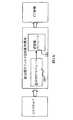
図1A、図1Bは、画像再構成アルゴリズム全体のモジュール図を示している。図1Aは従来型のフィルタ逆投影再構成、図1Bは反復再構成を示し、本発明は両者に応用することができる。フィルタ逆投影再構成では、図1Aに示すように、X線スキャンで得た投影データを重み付けモジュール105により加重(重み付け)した後、セパラブルフットプリント逆投影を行ってCT画像を得る。反復再構成では、図1Bに示すように、重み付けモジュール105が反復毎に加重し投影と逆投影プロセスを動作させる。動作手順は図8、図9における投影と逆投影フローを参照するものとする。図中、反復再構成アルゴリズムは主に、投影モジュール101、逆投影モジュール102、比較モジュール103、更新モジュール104を含む。このうち投影モジュール101と逆投影モジュール102はセパラブルフットプリント法に基づく投影・逆投影の演算を行う。重み付けモジュール105は、反復毎に加重することで投影と逆投影モデル精度を修正・向上させる。 1A and 1B show module diagrams of the entire image reconstruction algorithm. FIG. 1A shows a conventional filter backprojection reconstruction, and FIG. 1B shows an iterative reconstruction, and the present invention can be applied to both. In the filter backprojection reconstruction, as shown in FIG. 1A, the projection data obtained by the X-ray scan is weighted (weighted) by the
図2は、長さに基づく投影・逆投影加重の原理を示す図である。図中、投影線201がいずれかの画素202を通過する際の長さを、この投影線201と当該画素との間の相関係数、即ち、この投影線が投影される対応の検出器ユニット203の当該画素ユニットに対する投影と逆投影の加重係数であると定義する。この基本モデルは、セパラブルフットプリント投影・逆投影方法および本発明の基礎である。 FIG. 2 is a diagram showing the principle of length-based projection / backprojection weighting. In the figure, the length when the
図3は、セパラブルフットプリント投影・逆投影方法の原理とそのモデル誤差を示した図である。セパラブルフットプリント投影・逆投影方法において、所定の画素301に対する投影と逆投影は、X線源302から出発し、それぞれ画素301の4つの頂点を通り、検出器303上でそれぞれ対応する4つの位置に至る放射線の投影或いは逆投影である。投影プロセスでは、画素値はそれぞれ加重されてこの4つの位置範囲304内の検出器ユニットに積算される。ここで加重係数305は図3に示したように、検出器ユニットの位置の違いによって値が異なり、所定の画素301に対するセパラブルフットプリント投影の加重係数305は近似台形になり、台形の各頂点の横方向位置は4つの頂点の投影位置によって決定される。台形の高さは、投影線が画素を通過する距離で近似決定され、セパラブルフットプリント法において、加重係数は4つの頂点の投影が決定する位置範囲304の間では近似的に線形変化関係であるとしている。しかし、実際には、図中の幾何学関係および図2の加重原理からわかるように、4つの頂点の投影が決定する位置間の理想加重係数306は線形変化関係ではない。したがって、セパラブルフットプリント投影の加重係数305には一定の誤差が存在する。逆投影プロセスでも投影プロセスと同様に、4つの頂点の投影が決定する位置範囲304内の検出器値が加重係数305を用いて加重されて画素値に逆方向に積算されるため、同様の誤差が存在する。 FIG. 3 is a diagram showing the principle of the separable footprint projection / backprojection method and its model error. In the separable footprint projection / backprojection method, projection and backprojection on a
図4は、本実施形態における重み付け(補正係数)算出の原理を示している。図4によれば、重み付け(補正係数)は、X線401が所定の画素402の異なる位置を通過するとき、画素402通過時に切り取られる長さの幾何学関係に基づいて決定される。図中、線分(X線源からX線検出器に下ろした垂線405が画素402を切断する線)403の長さがセパラブルフットプリント法における加重値であるが、理想加重値は切断線(投影処理の対象となるX線401が画素402を切断する線)404の長さである。つまりセパラブルフットプリント法では切断線404の長さ値を線分403で近似代替し加重値としているが、この加重値は線分403と切断線404との間の幾何学関係により修正することができる。即ち重み付け(補正係数)の算出関数は、下記式(1)で表される。 FIG. 4 shows the principle of weighting (correction coefficient) calculation in this embodiment. According to FIG. 4, the weighting (correction coefficient) is determined based on the geometric relationship of lengths that are cut off when the

式(1)で、L403、L404はそれぞれ切断線403および線分404の長さを表し、θは射線401と線源から検出器に至る垂線405とがなす角度の余角を表す。In Expression (1), L403 and L404 represent the lengths of the
図5は、重み付け(補正係数)を算出するための関数を示した図と、重み付けベクトルを示した図を表している。投影において、X線501の経路上の全ての画素502値は、いずれも加重されて投影の対応検出器503に積算されるため、これらの画素値に対する補正係数はいずれも射線の角度のみに関係し、次式(2)で表される。 FIG. 5 shows a diagram showing a function for calculating a weight (correction coefficient) and a diagram showing a weight vector. In projection, all pixel 502 values on the path of the
式(2)で、P1、P2…、Pkは図のX線501の経路上の全ての画素502の画素値であり、W1、W2…、Wkはセパラブルフットプリント法における加重係数であり、1/sinθは補正係数、即ち重み付けである。式(2)は以下の式(3)に変換される。In Expression (2), P1 , P2 ..., Pk are pixel values of all the pixels 502 on the path of the
上式(3)からわかるように、各画素に対して加重補正した後に積算することは、加重積算後に補正する、即ち投影で得られる検出器ユニット値に補正を行うことと見なしてもよく、重み付け(補正係数)で検出器ユニット503値を再加重させる場合であっても、加重係数は、検出器ユニット503の位置とX線源から検出器に至る垂線504で決定される角度θに対応している。当該角度は次式(4)で算出することができる。 As can be seen from the above equation (3), the integration after performing weighted correction on each pixel may be regarded as correcting after the weighted integration, that is, correcting the detector unit value obtained by projection, Even when the
上式(4)で、L504は検出器のX線源から検出器に至る垂線の距離であり、L503は検出器ユニットのサイズであり、mは所定の検出器ユニットから垂線504と検出器との交点までの間の検出器の数である。こうして図5の505で示したような重み付けベクトルが得られる。In the above equation (4), L504 is the distance of a perpendicular line from the X-ray source of the detector to the detector, L503 is the size of the detector unit, and m is detected as a
図6は、重み付けベクトルによる検出器データ加重を示した図である。重み付けベクトル601取得後、投影と逆投影プロセスにおいて、検出器上の各列の検出器ユニットの検出器値で構成される検出器ベクトル602と重み付けベクトル601とを対応的に乗じて、補正された検出器ベクトル603を得る。 FIG. 6 is a diagram showing detector data weighting by weighting vectors. After obtaining the
以上、本実施形態のCT画像生成装置で用いられる重み付けベクトルの基本概念を説明したが、次に、上記重み付けベクトルを用いたCT画像生成装置の構造について説明する。 The basic concept of the weighting vector used in the CT image generation apparatus of this embodiment has been described above. Next, the structure of the CT image generation apparatus using the weighting vector will be described.
図7は、本実施形態のCT画像生成装置700のモジュール図である。
このCT画像生成装置700は、X線スキャナ701と、データインタフェースモジュール702と、画像形成装置703と、ユーザインタフェースモジュール704とを備えている。X線スキャナ701は、X線源と検出器を含み、被検体例えば人体をスキャンし投影データを得て、当該データを検出器データとする。データインタフェースモジュール702は、X線スキャナ701と画像形成装置703との間のインタフェースに接続される。ユーザインタフェースモジュール704は、表示、印刷、設定等の機能をユーザに提供する。画像形成装置703は、X線スキャナ701で得たスキャンデータを再構成してCT画像を形成するものであり、主に、記憶モジュール705、データバス706、および処理器モジュール707を含む。FIG. 7 is a module diagram of the CT
The CT
記憶モジュール705は、パラメータやデータを記憶するもので、主に、スキャナでスキャンした投影データおよびアルゴリズム過程で生成される投影データを記憶するための検出器データブロック708と、X線源と検出器ユニットの位置との幾何学関係に基づいて算出された重み付けベクトルを記憶するための重み付けデータブロック709と、CT装置の基本的な幾何学パラメータである、例えばX線源と検出器の相対的幾何学位置、モニタユニットのサイズ等を記憶するためのパラメータデータブロック710と、アルゴリズムで生成した結果画像を格納するための出力画像データブロック711と、を含む。 The storage module 705 stores parameters and data, and mainly includes a detector data block 708 for storing projection data scanned by a scanner and projection data generated in an algorithm process, an X-ray source and a detector. A weighting data block 709 for storing weighting vectors calculated based on the geometric relationship with the position of the unit, and the basic geometric parameters of the CT apparatus, for example the relative geometry of the X-ray source and detector A parameter data block 710 for storing the academic position, the size of the monitor unit, and the like, and an output image data block 711 for storing the result image generated by the algorithm are included.
データバス706は、処理器モジュール707と記憶モジュール705との間のデータ伝達用の通路である。処理器モジュール707は画像再構成アルゴリズムの算出処理に用いられ、主に、幾何学パラメータを用いて投影/逆投影角度ループを制御するアルゴリズムプロセスの処理モジュールを制御するための主処理器715と、本発明の特徴である重み付けベクトルを算出生成するための重み付け算出ユニット712と、重み付けベクトルと検出器データ(検出器ベクトル)との乗算処理を行い、補正された検出器値を得る重み付けベクトル乗法ユニット713と、前記補正された検出器値を用いてセパラブルフットプリント投影・逆投影アルゴリズムを実行するセパラブルフットプリント演算ユニット714とを含む。 The
CT画像生成装置700は、X線源と検出器の距離が、投影と逆投影の角度に伴って変化しない場合に用いることができ、この場合、CT画像生成装置700は、各角度で被検対象を照射して画像形成し、各角度で得られた画像を重畳させる。主処理器715は、投影/逆投影角度ループによって各角度の画像形成を制御する。 The CT
図8A、図8Bは、X線源と検出器の距離が、投影と逆投影の角度に伴って変化しない場合の、投影と逆投影プロセスの操作フローを示している。いずれのプロセスでも、先ず、CTの幾何学パラメータ値を取得し(801)、その後重み付けベクトルを算出する(802)。各投影と逆投影の角度に対し、投影プロセスでは、先ず元来のセパラブルフットプリント投影操作を行い(803)、その後、投影で得た投影結果ベクトルを重み付けベクトルで加重補正する(804)。逆投影プロセスでは、先ず検出器データを重み付けベクトルで加重し(805)、加重後の補正された検出器データにセパラブルフットプリント逆投影操作を行う(806)。こうして、その投影と逆投影の誤差を減少させて、投影と逆投影の精度を向上させ、CT画像のアーティファクトを低減することができる。 8A and 8B show the operational flow of the projection and backprojection process when the distance between the X-ray source and the detector does not change with the angle of projection and backprojection. In any process, first, a geometric parameter value of CT is acquired (801), and then a weighting vector is calculated (802). In the projection process, the original separable footprint projection operation is first performed for each projection and backprojection angle (803), and then the projection result vector obtained by the projection is weighted and corrected with a weighting vector (804). In the backprojection process, detector data is first weighted with a weighting vector (805), and a separable footprint backprojection operation is performed on the corrected detector data after weighting (806). Thus, errors in the projection and back projection can be reduced, the accuracy of projection and back projection can be improved, and artifacts in the CT image can be reduced.
CT画像生成装置700は、X線源と検出器との距離が、投影と逆投影の角度に応じて変化する場合にも用いることができる。図9A、図9Bは、X線源と検出器の相対位置が変化するときの、投影と逆投影プロセスの操作フロー図を示している。ここでも、まずCTの幾何学パラメータ値を取得すること(901)は、図8A、図8Bの操作フローと同じである。ただしX線源と検出器との間の距離が、投影と逆投影の角度に応じて変化しうるときは、距離の変化に基づき各角度における重み付けベクトルを算出する必要がある。投影プロセスでは、先ず現時点の投影角度における幾何学パラメータにより重み付けベクトルを算出してから(902)、元来のセパラブルフットプリント投影操作を行い(903)、その後、投影で得た投影結果ベクトルを重み付けベクトルで加重補正し(904)、角度が変わる毎に上記ステップ902〜904を繰り返す。逆投影プロセスでは、同様に、先ず現時点の投影角度における幾何学パラメータにより重み付けベクトルを算出し(902)、その後、検出器データを重み付けベクトルで加重してから(905)、加重後の補正された検出器データに対しセパラブルフットプリント逆投影操作を行う(906)。この場合にも、角度が変わる毎に上記ステップ902、905、906を繰り返す。 The CT
各角度ループにおいて、重み付けベクトルの計算量は検出器ユニットの数とのみ一次線形関係をなし、投影と逆投影操作に対する計算量としては非常に少ないことから、画像再構成プロセス全体の計算速度に及ぼす影響が極めて小さく、その速度性能に対する影響を無視できるため、反復再構成アルゴリズムの効率を向上させることができる。 In each angle loop, the amount of calculation of the weight vector has a linear relationship only with the number of detector units, and the amount of calculation for projection and backprojection operations is very small, which affects the calculation speed of the entire image reconstruction process. Since the influence is extremely small and the influence on the speed performance can be ignored, the efficiency of the iterative reconstruction algorithm can be improved.
上述の通り、図面を参照して本発明の実施形態を説明したが、上記説明はいずれかの態様で本発明を限定するものではないことを理解すべきである。当業者は本発明の実質的主旨と範囲から逸脱することなく、必要に応じて本発明を変形および変化させることができ、こうした変形および変化はいずれも本発明の範囲内である。 Although the embodiments of the present invention have been described with reference to the drawings as described above, it should be understood that the above descriptions do not limit the present invention in any way. Those skilled in the art can modify and change the present invention as necessary without departing from the substantial spirit and scope of the present invention, and all such modifications and changes are within the scope of the present invention.
302 X線源
303 検出器
505 重み付けベクトル
601 重み付けベクトル
700 CT画像生成装置
701 X線スキャナ
702 データインタフェースモジュール
704 ユーザインタフェースモジュール
705 記憶モジュール
707 処理器モジュール
708 検出器データブロック
709 重み付けデータブロック
710 パラメータデータブロック
711 出力画像データブロック
712 重み付け算出ユニット
713 重み付けベクトル乗法ユニット
714 セパラブルフットプリント演算ユニット
715 主処理器302
Claims (12)
Translated fromJapanese検出器データブロック、重み付けデータブロック、パラメータデータブロック、および入力/出力結果画像データブロックを含む記憶モジュールと、
主処理器、重み付け算出ユニット、重み付けベクトル乗法ユニット、およびセパラブルフットプリント演算ユニットを含む処理器モジュールと、
データインタフェースモジュールと、
ユーザインタフェースモジュールと、を備え、
前記X線スキャナがスキャンしたデータを、検出器データとして前記データインタフェースモジュールを介して前記検出器データブロックに記憶させ、
前記重み付け算出ユニットが、前記パラメータデータブロックから幾何学パラメータを取得するとともに、当該幾何学パラメータに基づいて重み付けベクトルを算出し、
前記主処理器が、前記幾何学パラメータを用いて投影/逆投影角度ループを制御し、
前記重み付けベクトル乗法ユニットが、前記検出器データに前記重み付けベクトルを乗じることにより、補正された検出器値を取得し、
前記セパラブルフットプリント演算ユニットが、前記補正された検出器値を用いて、セパラブルフットプリント投影・逆投影アルゴリズムを実行することを特徴とするCT画像生成装置。An X-ray scanner comprising an X-ray source and a detector for detecting an object disposed between the X-ray source and the detector;
A storage module including a detector data block, a weighted data block, a parameter data block, and an input / output result image data block;
A processor module including a main processor, a weighted calculation unit, a weighted vector multiplication unit, and a separable footprint computing unit;
A data interface module;
A user interface module;
The data scanned by the X-ray scanner is stored as detector data in the detector data block via the data interface module,
The weight calculation unit obtains a geometric parameter from the parameter data block, calculates a weight vector based on the geometric parameter,
The main processor controls the projection / backprojection angle loop using the geometric parameters;
The weighted vector multiplicative unit obtains a corrected detector value by multiplying the detector data by the weighted vector;
The separable footprint calculation unit executes a separable footprint projection / backprojection algorithm using the corrected detector value.
順投影では、先ずセパラブルフットプリント投影操作を行ってから、投影で得られた検出器データを重み付けベクトルで加重させることを特徴とする請求項1乃至3のいずれかに記載のCT画像生成装置。In the back projection, the main processor first weights the detector data with the weighting vector, and then performs a separable footprint back projection operation.
4. The CT image generation apparatus according to claim 1, wherein in the forward projection, a separable footprint projection operation is performed first, and then the detector data obtained by the projection is weighted with a weighting vector. 5. .
前記CT画像生成装置が、
X線源および検出器を備えて前記X線源と前記検出器の間に配置されたオブジェクトを検出するX線スキャナと、
検出器データブロック、重み付けデータブロック、パラメータデータブロック、および入力/出力結果画像データブロックを含む記憶モジュールと、
主処理器、重み付け算出ユニット、重み付けベクトル乗法ユニット、およびセパラブルフットプリント演算ユニットを含む処理器モジュールと、
データインタフェースモジュールと、
ユーザインタフェースモジュールと、を備え、
前記CT画像生成方法が、
前記X線スキャナがスキャンしたデータを、検出器データとして前記データインタフェースモジュールを介して前記検出器データブロックに記憶させるステップと、
前記重み付け算出ユニットが、前記パラメータデータブロックから幾何学パラメータを取得するとともに、当該幾何学パラメータに基づいて重み付けベクトルを算出するステップと、
前記主処理器が、前記幾何学パラメータを用いて投影/逆投影角度ループを制御するステップと、
前記重み付けベクトル乗法ユニットが、前記検出器データを前記重み付けベクトルに乗じることにより、改良された検出器値を取得するステップと、
前記セパラブルフットプリント演算ユニットが、前記改良された検出器値を用いて、セパラブルフットプリント投影・逆投影アルゴリズムを実行するステップと、を含むことを特徴とするCT画像生成装置のCT画像生成方法。In the CT image generation method of the CT image generation apparatus,
The CT image generation device comprises:
An X-ray scanner comprising an X-ray source and a detector for detecting an object disposed between the X-ray source and the detector;
A storage module including a detector data block, a weighted data block, a parameter data block, and an input / output result image data block;
A processor module including a main processor, a weighted calculation unit, a weighted vector multiplication unit, and a separable footprint computing unit;
A data interface module;
A user interface module;
The CT image generation method includes:
Storing the data scanned by the X-ray scanner in the detector data block via the data interface module as detector data;
The weight calculation unit obtains a geometric parameter from the parameter data block, and calculates a weight vector based on the geometric parameter;
Said main processor controlling a projection / backprojection angle loop using said geometric parameters;
The weighted vector multiplicative unit obtains an improved detector value by multiplying the weighted vector by the detector data;
CT image generation of a CT image generation device, wherein the separable footprint calculation unit includes a step of executing a separable footprint projection / backprojection algorithm using the improved detector value. Method.
前記X線源と前記検出器の距離が、投影と逆投影の角度に応じて変化するとき、
投影/逆投影角度ループにおける各々の角度毎に、前記パラメータデータブロックから幾何学パラメータを取得するとともに、前記距離に関連する重み付けベクトルを算出することを特徴とする請求項6に記載のCT画像生成方法。In the step of calculating the weighting vector,
When the distance between the X-ray source and the detector changes according to the angle of projection and back projection,
The CT image generation according to claim 6, wherein a geometric parameter is acquired from the parameter data block and a weighting vector related to the distance is calculated for each angle in a projection / backprojection angle loop. Method.
順投影では、先ずセパラブルフットプリント投影操作を行ってから、投影で得られた検出器データを重み付けで加重させることを特徴とする請求項6乃至8のいずれかに記載のCT画像生成方法。In backprojection, the detector data is first weighted with the weighting, then a separable footprint backprojection operation is performed,
9. The CT image generation method according to claim 6, wherein in the forward projection, a separable footprint projection operation is first performed, and then the detector data obtained by the projection is weighted by weighting.
主処理器、重み付け算出ユニット、重み付けベクトル乗法ユニット、およびセパラブルフットプリント演算ユニットを含む処理器モジュールと、
前記処理器モジュールで使用するパラメータを記憶する記憶モジュールと、を備え、
前記重み付け算出ユニットは、前記記憶モジュールから幾何学パラメータを読み出し、前記幾何学パラメータに基き重み付けベクトルを算出し、
前記主処理器は、前記幾何学パラメータを用いて投影/逆投影角度ループを制御し、
前記重み付けベクトル乗法ユニットは、前記X線スキャナがスキャンした検出器データに前記重み付けベクトルを乗じることにより、補正された検出器値を算出し、
前記セパラブルフットプリント演算ユニットは、前記補正された検出器値を用いて、セパラブルフットプリント投影・逆投影アルゴリズムを実行することを特徴とするCT画像生成装置。An X-ray scanner comprising an X-ray source and a detector for detecting an object disposed between the X-ray source and the detector;
A processor module including a main processor, a weighted calculation unit, a weighted vector multiplication unit, and a separable footprint computing unit;
A storage module for storing parameters used in the processor module;
The weight calculation unit reads a geometric parameter from the storage module, calculates a weight vector based on the geometric parameter,
The main processor uses the geometric parameters to control a projection / backprojection angle loop;
The weight vector multiplication unit multiplies the detector data scanned by the X-ray scanner by the weight vector to calculate a corrected detector value;
The separable footprint calculation unit executes a separable footprint projection / backprojection algorithm using the corrected detector value.
記憶モジュールに記憶された幾何学パラメータを用いて重み付けベクトルを算出するステップと、
前記幾何学パラメータを用いて投影/逆投影角度ループを制御するステップと、
前記検出器データに前記重み付けベクトルを乗じることにより、補正された検出器値を取得するステップと、
前記補正された検出器値を用いて、セパラブルフットプリント投影・逆投影アルゴリズムを実行するステップと、を含むことを特徴とするCT画像生成装置のCT画像生成方法。Storing the data scanned by the X-ray scanner as detector data;
Calculating a weighting vector using the geometric parameters stored in the storage module;
Controlling a projection / backprojection angle loop using said geometric parameters;
Obtaining a corrected detector value by multiplying the detector data by the weighting vector;
Performing a separable footprint projection / backprojection algorithm using the corrected detector value, and a CT image generation method for a CT image generation apparatus.
Applications Claiming Priority (3)
| Application Number | Priority Date | Filing Date | Title |
|---|---|---|---|
| CN201310050641.3 | 2013-02-08 | ||
| CN201310050641.3ACN103976753B (en) | 2013-02-08 | 2013-02-08 | CT video generation device and CT image generating method |
| PCT/JP2013/082226WO2014122840A1 (en) | 2013-02-08 | 2013-11-29 | Ct image generation device and ct image generation method |
Publications (2)
| Publication Number | Publication Date |
|---|---|
| JP6014174B2true JP6014174B2 (en) | 2016-10-25 |
| JPWO2014122840A1 JPWO2014122840A1 (en) | 2017-01-26 |
Family
ID=51269101
Family Applications (1)
| Application Number | Title | Priority Date | Filing Date |
|---|---|---|---|
| JP2014560646AExpired - Fee RelatedJP6014174B2 (en) | 2013-02-08 | 2013-11-29 | CT image generation apparatus and CT image generation method |
Country Status (3)
| Country | Link |
|---|---|
| JP (1) | JP6014174B2 (en) |
| CN (1) | CN103976753B (en) |
| WO (1) | WO2014122840A1 (en) |
Families Citing this family (5)
| Publication number | Priority date | Publication date | Assignee | Title |
|---|---|---|---|---|
| CN106683146B (en)* | 2017-01-11 | 2021-01-15 | 上海联影医疗科技股份有限公司 | Image reconstruction method and parameter determination method of image reconstruction algorithm |
| EP3675740B1 (en) | 2017-08-28 | 2022-06-15 | Shanghai United Imaging Healthcare Co., Ltd. | Systems and methods for determining rotation angles |
| CN108492341B (en)* | 2018-02-05 | 2022-02-25 | 西安电子科技大学 | Parallel beam projection method based on pixel vertex |
| TWI701533B (en)* | 2019-11-14 | 2020-08-11 | 緯創資通股份有限公司 | Control method and electrical walker |
| CN116206007B (en)* | 2023-03-22 | 2023-09-29 | 北京朗视仪器股份有限公司 | CBCT image truncation artifact suppression method |
Citations (6)
| Publication number | Priority date | Publication date | Assignee | Title |
|---|---|---|---|---|
| US6137856A (en)* | 1998-12-14 | 2000-10-24 | General Electric Company | Generic architectures for backprojection algorithm |
| JP2005522304A (en)* | 2002-04-15 | 2005-07-28 | ゼネラル・エレクトリック・カンパニイ | Projection method, back projection method and execution algorithm thereof |
| JP2010115475A (en)* | 2008-11-11 | 2010-05-27 | Toshiba Corp | Apparatus and method for computed tomography |
| JP2010253114A (en)* | 2009-04-27 | 2010-11-11 | Hitachi Ltd | Image reconstruction method, X-ray CT apparatus, and program |
| WO2012069964A1 (en)* | 2010-11-25 | 2012-05-31 | Koninklijke Philips Electronics N.V. | Forward projection apparatus |
| JP2012220422A (en)* | 2011-04-12 | 2012-11-12 | Shimadzu Corp | Tomogram image reconstruction method and x-ray ct apparatus |
Family Cites Families (2)
| Publication number | Priority date | Publication date | Assignee | Title |
|---|---|---|---|---|
| US8913805B2 (en)* | 2010-08-30 | 2014-12-16 | The Regents Of The University Of Michigan | Three-dimensional forward and back projection methods |
| CN103310471B (en)* | 2012-03-09 | 2016-01-13 | 株式会社日立医疗器械 | CT video generation device and method, CT image generation system |
- 2013
- 2013-02-08CNCN201310050641.3Apatent/CN103976753B/ennot_activeExpired - Fee Related
- 2013-11-29JPJP2014560646Apatent/JP6014174B2/ennot_activeExpired - Fee Related
- 2013-11-29WOPCT/JP2013/082226patent/WO2014122840A1/enactiveApplication Filing
Patent Citations (6)
| Publication number | Priority date | Publication date | Assignee | Title |
|---|---|---|---|---|
| US6137856A (en)* | 1998-12-14 | 2000-10-24 | General Electric Company | Generic architectures for backprojection algorithm |
| JP2005522304A (en)* | 2002-04-15 | 2005-07-28 | ゼネラル・エレクトリック・カンパニイ | Projection method, back projection method and execution algorithm thereof |
| JP2010115475A (en)* | 2008-11-11 | 2010-05-27 | Toshiba Corp | Apparatus and method for computed tomography |
| JP2010253114A (en)* | 2009-04-27 | 2010-11-11 | Hitachi Ltd | Image reconstruction method, X-ray CT apparatus, and program |
| WO2012069964A1 (en)* | 2010-11-25 | 2012-05-31 | Koninklijke Philips Electronics N.V. | Forward projection apparatus |
| JP2012220422A (en)* | 2011-04-12 | 2012-11-12 | Shimadzu Corp | Tomogram image reconstruction method and x-ray ct apparatus |
Also Published As
| Publication number | Publication date |
|---|---|
| WO2014122840A1 (en) | 2014-08-14 |
| CN103976753A (en) | 2014-08-13 |
| JPWO2014122840A1 (en) | 2017-01-26 |
| CN103976753B (en) | 2016-08-17 |
Similar Documents
| Publication | Publication Date | Title |
|---|---|---|
| US8705828B2 (en) | Methods and apparatus for super resolution scanning for CBCT system and cone-beam image reconstruction | |
| US6292530B1 (en) | Method and apparatus for reconstructing image data acquired by a tomosynthesis x-ray imaging system | |
| JP6014174B2 (en) | CT image generation apparatus and CT image generation method | |
| JP6370280B2 (en) | Tomographic image generating apparatus, method and program | |
| JP6026214B2 (en) | X-ray computed tomography apparatus (X-ray CT apparatus), medical image processing apparatus, and medical image processing method for supplementing detailed images in continuous multiscale reconstruction | |
| KR20130069506A (en) | Image processing apparatus, image processing method, and computer-readable storage medium | |
| US12182970B2 (en) | X-ray imaging restoration using deep learning algorithms | |
| US9734574B2 (en) | Image processor, treatment system, and image processing method | |
| CN104182932B (en) | CT (Computed Tomography) device, CT image system and CT image generation method | |
| CN105326524B (en) | The medical imaging procedure and device of the artifact in image can be reduced | |
| US10013778B2 (en) | Tomography apparatus and method of reconstructing tomography image by using the tomography apparatus | |
| CN103310471B (en) | CT video generation device and method, CT image generation system | |
| JP6185023B2 (en) | Tomographic image generating apparatus, method and program | |
| CN110533738B (en) | Reconstruction data processing method, device, medical imaging system and storage medium | |
| WO2022045210A1 (en) | Image processing device, image processing method, learning device, learning method, and program | |
| JP2019130083A (en) | Image processing apparatus, radiation imaging apparatus, image processing method, and program | |
| CN109716394A (en) | The reconstruction of motion compensation for spiral computerized tomography | |
| JP6398685B2 (en) | Tomographic image generation system and image processing apparatus | |
| JP2015089452A (en) | Image processing apparatus, image processing method, and program | |
| JP3921971B2 (en) | Tomographic reconstruction method and tomography apparatus | |
| JP6167841B2 (en) | Medical image processing apparatus and program | |
| US20230094397A1 (en) | Learning device, image generation device, learning method, image generation method, learning program, and image generation program | |
| JP6778158B2 (en) | X-ray CT equipment, image generation method and image generation program | |
| TWI613998B (en) | Reduction method for boundary artifact on the tomosynthesis | |
| JP2016039902A (en) | X-ray computer tomographic apparatus and medical image processing apparatus |
Legal Events
| Date | Code | Title | Description |
|---|---|---|---|
| TRDD | Decision of grant or rejection written | ||
| A01 | Written decision to grant a patent or to grant a registration (utility model) | Free format text:JAPANESE INTERMEDIATE CODE: A01 Effective date:20160913 | |
| A61 | First payment of annual fees (during grant procedure) | Free format text:JAPANESE INTERMEDIATE CODE: A61 Effective date:20160923 | |
| R150 | Certificate of patent or registration of utility model | Ref document number:6014174 Country of ref document:JP Free format text:JAPANESE INTERMEDIATE CODE: R150 | |
| LAPS | Cancellation because of no payment of annual fees |