JP6013389B2 - Hydraulic system of work machine - Google Patents
Hydraulic system of work machineDownload PDFInfo
- Publication number
- JP6013389B2 JP6013389B2JP2014060890AJP2014060890AJP6013389B2JP 6013389 B2JP6013389 B2JP 6013389B2JP 2014060890 AJP2014060890 AJP 2014060890AJP 2014060890 AJP2014060890 AJP 2014060890AJP 6013389 B2JP6013389 B2JP 6013389B2
- Authority
- JP
- Japan
- Prior art keywords
- flow rate
- control valve
- direction control
- hydraulic
- optional
- Prior art date
- Legal status (The legal status is an assumption and is not a legal conclusion. Google has not performed a legal analysis and makes no representation as to the accuracy of the status listed.)
- Active
Links
- 238000001514detection methodMethods0.000claimsdescription12
- 230000000903blocking effectEffects0.000claims1
- 239000003921oilSubstances0.000description186
- 238000010586diagramMethods0.000description20
- 230000006870functionEffects0.000description17
- 230000000694effectsEffects0.000description10
- 239000010720hydraulic oilSubstances0.000description10
- 238000009434installationMethods0.000description6
- 230000006866deteriorationEffects0.000description5
- 239000000446fuelSubstances0.000description5
- 230000007935neutral effectEffects0.000description3
- 238000005516engineering processMethods0.000description2
- 230000005856abnormalityEffects0.000description1
- 230000008602contractionEffects0.000description1
- 238000006073displacement reactionMethods0.000description1
- 230000001747exhibiting effectEffects0.000description1
- 230000007659motor functionEffects0.000description1
- 230000009466transformationEffects0.000description1
- 238000011144upstream manufacturingMethods0.000description1
Images


Classifications
- E—FIXED CONSTRUCTIONS
- E02—HYDRAULIC ENGINEERING; FOUNDATIONS; SOIL SHIFTING
- E02F—DREDGING; SOIL-SHIFTING
- E02F3/00—Dredgers; Soil-shifting machines
- E02F3/04—Dredgers; Soil-shifting machines mechanically-driven
- E02F3/96—Dredgers; Soil-shifting machines mechanically-driven with arrangements for alternate or simultaneous use of different digging elements
- E02F3/963—Arrangements on backhoes for alternate use of different tools
- E—FIXED CONSTRUCTIONS
- E02—HYDRAULIC ENGINEERING; FOUNDATIONS; SOIL SHIFTING
- E02F—DREDGING; SOIL-SHIFTING
- E02F9/00—Component parts of dredgers or soil-shifting machines, not restricted to one of the kinds covered by groups E02F3/00 - E02F7/00
- E02F9/20—Drives; Control devices
- E02F9/22—Hydraulic or pneumatic drives
- E02F9/2221—Control of flow rate; Load sensing arrangements
- E02F9/2225—Control of flow rate; Load sensing arrangements using pressure-compensating valves
- E02F9/2228—Control of flow rate; Load sensing arrangements using pressure-compensating valves including an electronic controller
- E—FIXED CONSTRUCTIONS
- E02—HYDRAULIC ENGINEERING; FOUNDATIONS; SOIL SHIFTING
- E02F—DREDGING; SOIL-SHIFTING
- E02F9/00—Component parts of dredgers or soil-shifting machines, not restricted to one of the kinds covered by groups E02F3/00 - E02F7/00
- E02F9/20—Drives; Control devices
- E02F9/2004—Control mechanisms, e.g. control levers
- E02F9/2012—Setting the functions of the control levers, e.g. changing assigned functions among operations levers, setting functions dependent on the operator or seat orientation
- E—FIXED CONSTRUCTIONS
- E02—HYDRAULIC ENGINEERING; FOUNDATIONS; SOIL SHIFTING
- E02F—DREDGING; SOIL-SHIFTING
- E02F9/00—Component parts of dredgers or soil-shifting machines, not restricted to one of the kinds covered by groups E02F3/00 - E02F7/00
- E02F9/20—Drives; Control devices
- E02F9/22—Hydraulic or pneumatic drives
- E02F9/2221—Control of flow rate; Load sensing arrangements
- E02F9/2225—Control of flow rate; Load sensing arrangements using pressure-compensating valves
- E—FIXED CONSTRUCTIONS
- E02—HYDRAULIC ENGINEERING; FOUNDATIONS; SOIL SHIFTING
- E02F—DREDGING; SOIL-SHIFTING
- E02F9/00—Component parts of dredgers or soil-shifting machines, not restricted to one of the kinds covered by groups E02F3/00 - E02F7/00
- E02F9/20—Drives; Control devices
- E02F9/22—Hydraulic or pneumatic drives
- E02F9/2264—Arrangements or adaptations of elements for hydraulic drives
- E02F9/2267—Valves or distributors
- E—FIXED CONSTRUCTIONS
- E02—HYDRAULIC ENGINEERING; FOUNDATIONS; SOIL SHIFTING
- E02F—DREDGING; SOIL-SHIFTING
- E02F9/00—Component parts of dredgers or soil-shifting machines, not restricted to one of the kinds covered by groups E02F3/00 - E02F7/00
- E02F9/20—Drives; Control devices
- E02F9/22—Hydraulic or pneumatic drives
- E02F9/2278—Hydraulic circuits
- E02F9/2282—Systems using center bypass type changeover valves
- E—FIXED CONSTRUCTIONS
- E02—HYDRAULIC ENGINEERING; FOUNDATIONS; SOIL SHIFTING
- E02F—DREDGING; SOIL-SHIFTING
- E02F9/00—Component parts of dredgers or soil-shifting machines, not restricted to one of the kinds covered by groups E02F3/00 - E02F7/00
- E02F9/20—Drives; Control devices
- E02F9/22—Hydraulic or pneumatic drives
- E02F9/2278—Hydraulic circuits
- E02F9/2285—Pilot-operated systems
- E—FIXED CONSTRUCTIONS
- E02—HYDRAULIC ENGINEERING; FOUNDATIONS; SOIL SHIFTING
- E02F—DREDGING; SOIL-SHIFTING
- E02F9/00—Component parts of dredgers or soil-shifting machines, not restricted to one of the kinds covered by groups E02F3/00 - E02F7/00
- E02F9/20—Drives; Control devices
- E02F9/22—Hydraulic or pneumatic drives
- E02F9/2278—Hydraulic circuits
- E02F9/2292—Systems with two or more pumps
- E—FIXED CONSTRUCTIONS
- E02—HYDRAULIC ENGINEERING; FOUNDATIONS; SOIL SHIFTING
- E02F—DREDGING; SOIL-SHIFTING
- E02F9/00—Component parts of dredgers or soil-shifting machines, not restricted to one of the kinds covered by groups E02F3/00 - E02F7/00
- E02F9/20—Drives; Control devices
- E02F9/22—Hydraulic or pneumatic drives
- E02F9/2278—Hydraulic circuits
- E02F9/2296—Systems with a variable displacement pump
- F—MECHANICAL ENGINEERING; LIGHTING; HEATING; WEAPONS; BLASTING
- F15—FLUID-PRESSURE ACTUATORS; HYDRAULICS OR PNEUMATICS IN GENERAL
- F15B—SYSTEMS ACTING BY MEANS OF FLUIDS IN GENERAL; FLUID-PRESSURE ACTUATORS, e.g. SERVOMOTORS; DETAILS OF FLUID-PRESSURE SYSTEMS, NOT OTHERWISE PROVIDED FOR
- F15B11/00—Servomotor systems without provision for follow-up action; Circuits therefor
- F15B11/08—Servomotor systems without provision for follow-up action; Circuits therefor with only one servomotor
- F—MECHANICAL ENGINEERING; LIGHTING; HEATING; WEAPONS; BLASTING
- F15—FLUID-PRESSURE ACTUATORS; HYDRAULICS OR PNEUMATICS IN GENERAL
- F15B—SYSTEMS ACTING BY MEANS OF FLUIDS IN GENERAL; FLUID-PRESSURE ACTUATORS, e.g. SERVOMOTORS; DETAILS OF FLUID-PRESSURE SYSTEMS, NOT OTHERWISE PROVIDED FOR
- F15B13/00—Details of servomotor systems ; Valves for servomotor systems
- F15B13/02—Fluid distribution or supply devices characterised by their adaptation to the control of servomotors
- F15B13/04—Fluid distribution or supply devices characterised by their adaptation to the control of servomotors for use with a single servomotor
- F15B13/0401—Valve members; Fluid interconnections therefor
- E—FIXED CONSTRUCTIONS
- E02—HYDRAULIC ENGINEERING; FOUNDATIONS; SOIL SHIFTING
- E02F—DREDGING; SOIL-SHIFTING
- E02F3/00—Dredgers; Soil-shifting machines
- E02F3/04—Dredgers; Soil-shifting machines mechanically-driven
- E02F3/28—Dredgers; Soil-shifting machines mechanically-driven with digging tools mounted on a dipper- or bucket-arm, i.e. there is either one arm or a pair of arms, e.g. dippers, buckets
- E02F3/30—Dredgers; Soil-shifting machines mechanically-driven with digging tools mounted on a dipper- or bucket-arm, i.e. there is either one arm or a pair of arms, e.g. dippers, buckets with a dipper-arm pivoted on a cantilever beam, i.e. boom
- E02F3/32—Dredgers; Soil-shifting machines mechanically-driven with digging tools mounted on a dipper- or bucket-arm, i.e. there is either one arm or a pair of arms, e.g. dippers, buckets with a dipper-arm pivoted on a cantilever beam, i.e. boom working downwardly and towards the machine, e.g. with backhoes
- F—MECHANICAL ENGINEERING; LIGHTING; HEATING; WEAPONS; BLASTING
- F15—FLUID-PRESSURE ACTUATORS; HYDRAULICS OR PNEUMATICS IN GENERAL
- F15B—SYSTEMS ACTING BY MEANS OF FLUIDS IN GENERAL; FLUID-PRESSURE ACTUATORS, e.g. SERVOMOTORS; DETAILS OF FLUID-PRESSURE SYSTEMS, NOT OTHERWISE PROVIDED FOR
- F15B2211/00—Circuits for servomotor systems
- F15B2211/30—Directional control
- F15B2211/305—Directional control characterised by the type of valves
- F15B2211/30505—Non-return valves, i.e. check valves
- F15B2211/30515—Load holding valves
- F—MECHANICAL ENGINEERING; LIGHTING; HEATING; WEAPONS; BLASTING
- F15—FLUID-PRESSURE ACTUATORS; HYDRAULICS OR PNEUMATICS IN GENERAL
- F15B—SYSTEMS ACTING BY MEANS OF FLUIDS IN GENERAL; FLUID-PRESSURE ACTUATORS, e.g. SERVOMOTORS; DETAILS OF FLUID-PRESSURE SYSTEMS, NOT OTHERWISE PROVIDED FOR
- F15B2211/00—Circuits for servomotor systems
- F15B2211/40—Flow control
- F—MECHANICAL ENGINEERING; LIGHTING; HEATING; WEAPONS; BLASTING
- F15—FLUID-PRESSURE ACTUATORS; HYDRAULICS OR PNEUMATICS IN GENERAL
- F15B—SYSTEMS ACTING BY MEANS OF FLUIDS IN GENERAL; FLUID-PRESSURE ACTUATORS, e.g. SERVOMOTORS; DETAILS OF FLUID-PRESSURE SYSTEMS, NOT OTHERWISE PROVIDED FOR
- F15B2211/00—Circuits for servomotor systems
- F15B2211/50—Pressure control
- F15B2211/505—Pressure control characterised by the type of pressure control means
- F15B2211/50509—Pressure control characterised by the type of pressure control means the pressure control means controlling a pressure upstream of the pressure control means
- F—MECHANICAL ENGINEERING; LIGHTING; HEATING; WEAPONS; BLASTING
- F15—FLUID-PRESSURE ACTUATORS; HYDRAULICS OR PNEUMATICS IN GENERAL
- F15B—SYSTEMS ACTING BY MEANS OF FLUIDS IN GENERAL; FLUID-PRESSURE ACTUATORS, e.g. SERVOMOTORS; DETAILS OF FLUID-PRESSURE SYSTEMS, NOT OTHERWISE PROVIDED FOR
- F15B2211/00—Circuits for servomotor systems
- F15B2211/70—Output members, e.g. hydraulic motors or cylinders or control therefor
- F15B2211/71—Multiple output members, e.g. multiple hydraulic motors or cylinders
- F15B2211/7135—Combinations of output members of different types, e.g. single-acting cylinders with rotary motors
Landscapes
- Engineering & Computer Science (AREA)
- General Engineering & Computer Science (AREA)
- Mining & Mineral Resources (AREA)
- Civil Engineering (AREA)
- Structural Engineering (AREA)
- Physics & Mathematics (AREA)
- Fluid Mechanics (AREA)
- Mechanical Engineering (AREA)
- Operation Control Of Excavators (AREA)
- Fluid-Pressure Circuits (AREA)
Description
Translated fromJapanese本発明は、作業機械の油圧システムに係わり、特にフロント作業機を油圧シリンダ等で操作する油圧ショベル等の作業機械の油圧システムに関する。 The present invention relates to a hydraulic system for a work machine, and more particularly to a hydraulic system for a work machine such as a hydraulic excavator that operates a front work machine with a hydraulic cylinder or the like.
油圧ショベル等の作業機械の油圧システムは、特許文献1に記載のように、一般に、油圧ポンプと、この油圧ポンプの吐出油により駆動される油圧アクチュエータと、油圧ポンプから油圧アクチュエータに供給される圧油の流れを制御するセンターバイパス型の流量・方向制御弁と、油圧アクチュエータに対応して設けられ、流量・方向制御弁をそれぞれ操作する操作手段と、操作手段の操作に応じて油圧ポンプの吐出量が変化するように油圧ポンプの容量を制御するポンプレギュレータとを備えている。 As described in
油圧ショベル等の作業機械の油圧システムには、種々の目的で、センターバイパス型の流量・方向制御弁を貫通するセンターバイパスラインの最下流側にセンターバイパスカット弁を配置したものがある。特許文献1はその一例であり、負荷保持側のシリンダ室に圧油を供給するよう操作されたときにセンターバイパスカット弁をセンターバイパス開口面積を狭くする方向に作動させ、油圧ポンプの吐出圧力がシリンダの負荷圧よりも高くなるように制御し、エネルギーロスを低減して燃費の悪化を防止し、かつ良好な微速操作性を得られるようにしている。 Some hydraulic systems of work machines such as hydraulic excavators have a center bypass cut valve arranged on the most downstream side of a center bypass line that passes through a center bypass flow / direction control valve for various purposes.
また、近年、上部旋回体を油圧モータと電動機とにより駆動することで、上部旋回体の減速或いは停止時に電動機を発電機として機能させてエネルギーを電力として回生し、エネルギー効率を改善する作業機械が提案されている。
その一例として、特許文献2に記載の作業機械では、センターバイパスカット弁をコントロールバルブユニットに通常備えられる予備スプールを利用して構成し、旋回用電動機を非駆動としたときにこの予備スプールを制御して、方向・流量制御弁のブリードオフ絞りと予備スプールのブリードオフ絞りとの合成絞りによりオープンセンタ油路を絞ることで旋回用油圧モータのメータイン圧力が上昇するよう制御し、以て旋回用油圧モータの駆動トルクを増加させるように制御している。これにより、電動機の故障、蓄電装置の電圧異常、その他の理由により電動機の機能を停止する必要が生じたときであっても良好な操作感と作業能力を確保している。Also, in recent years, there is a work machine that improves energy efficiency by driving an upper swing body with a hydraulic motor and an electric motor so that the motor functions as a generator when the upper swing body is decelerated or stopped to regenerate energy as electric power. Proposed.
As an example, in the work machine described in
しかしながら、特許文献1記載の油圧システムにおいては、センターバイパス型の流量・方向制御弁を貫通するセンターバイパスラインの最下流にセンターバイパスカット弁を搭載するスペースとコストが必要になる。 However, in the hydraulic system described in
この特許文献1に記載の技術に、特許文献2に記載のように予備スプールを利用してセンターバイパスカット弁を構成する技術を単純に適用すると、センターバイパスラインの最下流にセンターバイパスカット弁を搭載するスペースとコストを不要とすることは可能である。 When the technology for configuring the center bypass cut valve using the spare spool as described in
しかし、作業機械にアタッチメントを装着する場合には、予備スプールはアタッチメントの油圧アクチュエータに供給する圧油の流れを制御する流量・方向制御弁として使用するためにセンターバイパスカット弁として使用することができず、センターバイパス開口面積の制御を行うことができないとの問題が生じる。このため、アタッチメント装着時にはエネルギーロスを低減して燃費の悪化を防止することができず、また良好な微速操作性を得られない、との問題がある。 However, when attaching an attachment to the work machine, the spare spool can be used as a center bypass cut valve to be used as a flow rate / direction control valve for controlling the flow of pressure oil supplied to the hydraulic actuator of the attachment. Therefore, there arises a problem that the center bypass opening area cannot be controlled. For this reason, when attaching the attachment, there is a problem that energy loss cannot be reduced to prevent deterioration of fuel consumption, and good fine speed operability cannot be obtained.
本発明は、専用のセンターバイパスカット弁を備えることなく、アタッチメント装着時においてもセンターバイパス開口面積の制御を行える作業機械の油圧システムを提供することを目的とする。 An object of this invention is to provide the hydraulic system of the working machine which can control a center bypass opening area also at the time of attachment attachment, without providing a dedicated center bypass cut valve.
上記目的を達成するために、第1の発明は、油圧ポンプと、この油圧ポンプの吐出油により駆動される油圧アクチュエータと、前記油圧ポンプから前記油圧アクチュエータに供給される圧油の流れを制御するセンターバイパス型の流量・方向制御弁と、この流量・方向制御弁を貫通するセンターバイパスラインの前記流量・方向制御弁の下流側の位置に配置された予備流量・方向制御弁であって、オプション油圧アクチュエータの使用時に前記油圧ポンプから前記オプション油圧アクチュエータに供給される圧油の流れを制御するためのセンターバイパス型の予備流量・方向制御弁と、前記オプション油圧アクチュエータを動作させるときは、前記予備流量・方向制御弁を前記オプション油圧アクチュエータに供給する圧油の流れを制御するバルブとして作動させ、前記オプション油圧アクチュエータを動作させないときは、前記予備流量・方向制御弁をセンターバイパスカット弁として作動させる切替制御装置とを備えることを特徴とするものである。 To achieve the above object, the first invention controls a hydraulic pump, a hydraulic actuator driven by oil discharged from the hydraulic pump, and a flow of pressure oil supplied from the hydraulic pump to the hydraulic actuator. Center bypass type flow rate / direction control valve and a preliminary flow rate / direction control valve disposed at a position downstream of the flow rate / direction control valve of the center bypass line passing through the flow rate / direction control valve. A center bypass type preliminary flow rate / direction control valve for controlling the flow of pressure oil supplied from the hydraulic pump to the optional hydraulic actuator when the hydraulic actuator is used, and when operating the optional hydraulic actuator, Controls the flow of pressure oil that supplies a flow / direction control valve to the optional hydraulic actuator. Is operated as Lube, when the option is not the hydraulic actuator is operated is to anda the preliminary flow and direction control valve switching control device for actuating the center bypass cut valve.
かかる構成により、オプションアタッチメント装着・未使用時は、オプションアタッチメント未装着時と同様に、予備流量・方向制御弁をセンターバイパスカット弁として作動させることができ、重負荷微速操作作業時において、専用のセンターバイパスカット弁を備えることなく、エネルギーロスを低減して燃費の悪化を防止することができるとともに良好な微速操作性を得られる、との効果を奏することができる。 With this configuration, when the optional attachment is installed / not used, the reserve flow / direction control valve can be operated as a center bypass cut valve, just as when the optional attachment is not installed. Without providing a center bypass cut valve, it is possible to reduce energy loss and prevent deterioration of fuel consumption, and to obtain good fine speed operability.
また、第2の発明は、第1の発明において、前記切替制御装置は、前記予備流量・方向制御弁の作動を切り替えるためのスイッチを有するものである。 In a second aspect based on the first aspect, the switching control device has a switch for switching the operation of the preliminary flow rate / direction control valve.
かかる構成により、オプションアタッチメント装着・未使用時にオプション油圧アクチュエータに圧油が供給されないようにする、すなわちオプションアタッチメントが動作しないようにすることができ、オペレータの意図しない動作が実行されることを防止することができる。 With this configuration, it is possible to prevent pressure oil from being supplied to the optional hydraulic actuator when the option attachment is mounted or not used, that is, to prevent the option attachment from operating, and prevent an operation not intended by the operator from being performed. be able to.
また、第3の発明は、第1の発明において、前記切替制御装置は、前記予備流量・方向制御弁を前記オプション油圧アクチュエータの流量・方向制御弁として作動させない状態にあることを検知するセンサを更に備え、前記切替制御装置は、このセンサから出力された検知信号を基にして前記予備流量・方向制御弁の作動を切り替える制御を行うものである。 According to a third aspect, in the first aspect, the switching control device includes a sensor that detects that the preliminary flow rate / direction control valve is not operated as a flow rate / direction control valve of the optional hydraulic actuator. Further, the switching control device performs control to switch the operation of the preliminary flow rate / direction control valve based on the detection signal output from the sensor.
かかる構成により、回路構成が簡単となり、より低コストの油圧システムとすることができる。また、オプションアタッチメントの操作によって予備流量・方向制御弁の機能が切り替わるため、操作も容易である。 With this configuration, the circuit configuration is simplified and a lower cost hydraulic system can be obtained. In addition, since the function of the preliminary flow rate / direction control valve is switched by the operation of the option attachment, the operation is easy.
また、第4の発明は、第2または第3の発明において、前記予備流量・方向制御弁から前記オプション油圧アクチュエータに圧油を供給するアクチュエータ油路に配置された開閉バルブを更に備え、前記切替制御装置は、前記予備流量・方向制御弁をセンターバイパスカット弁として作動させるときに前記開閉バルブを閉じて前記油路を遮断するよう制御するものである。 According to a fourth aspect of the present invention, in the second or third aspect of the present invention, the switching device further includes an on-off valve disposed in an actuator oil passage that supplies pressure oil from the preliminary flow rate / direction control valve to the optional hydraulic actuator. The control device controls to close the on-off valve and shut off the oil passage when the preliminary flow rate / direction control valve is operated as a center bypass cut valve.
かかる構成により、オプションアタッチメントが装着されている際に、予備流量・方向制御弁をセンターバイパスカット弁として作動させる際に、オプション油圧アクチュエータに圧油が供給されることを確実に防止することができ、オペレータの意図しない動作が実行されることを防止することができる。 With this configuration, when the optional attachment is installed, it is possible to reliably prevent pressure oil from being supplied to the optional hydraulic actuator when operating the preliminary flow rate / direction control valve as the center bypass cut valve. Thus, it is possible to prevent an operation not intended by the operator from being performed.
また、第5の発明は、第1の発明において、前記予備流量・方向制御弁は、前記オプション油圧アクチュエータに圧油を供給する第1位置と、前記オプション油圧アクチュエータへの圧油の供給を遮断する第2位置とに切り換え可能であり、前記切替制御装置は、前記予備流量・方向制御弁を前記オプション油圧アクチュエータに供給する圧油の流れを制御するバルブとして作動させるとき、前記予備流量・方向制御弁を前記第1位置に切り換え、前記予備流量・方向制御弁をセンターバイパスカット弁として作動させるとき、前記予備流量・方向制御弁を前記第2位置に切り換えるよう制御するものである。 In a fifth aspect based on the first aspect, the preliminary flow rate / direction control valve shuts off the first position for supplying pressure oil to the optional hydraulic actuator and the supply of pressure oil to the optional hydraulic actuator. And the switching control device operates the preliminary flow rate / direction when the preliminary flow rate / direction control valve is operated as a valve for controlling the flow of pressure oil supplied to the optional hydraulic actuator. When the control valve is switched to the first position and the reserve flow / direction control valve is operated as a center bypass cut valve, the reserve flow / direction control valve is controlled to be switched to the second position.
かかる構成により、圧油がオプション油圧アクチュエータの一方の側のシリンダ室にのみ供給される態様に好適な油圧システムとなる。 With this configuration, the hydraulic system is suitable for a mode in which the pressure oil is supplied only to the cylinder chamber on one side of the optional hydraulic actuator.
本発明によれば、オプション油圧アクチュエータを搭載している際に、予備流量・方向制御弁のセンターバイパスの合成開口面積を調整する機能とそのオプション油圧アクチュエータに圧油を供給する機能を切り替えることができる。これにより、専用のセンターバイパスカット弁を備えることなく、アタッチメント装着時においてもセンターバイパス開口面積の制御を行うことができる。従って、アタッチメント装着時にもエネルギーロスを低減して燃費の悪化を防止することができるとともに良好な微速操作性を得られる、との効果を奏することができる。 According to the present invention, when the optional hydraulic actuator is mounted, the function of adjusting the synthetic opening area of the center bypass of the preliminary flow rate / direction control valve and the function of supplying pressure oil to the optional hydraulic actuator can be switched. it can. Thereby, the center bypass opening area can be controlled even when the attachment is mounted without providing a dedicated center bypass cut valve. Therefore, even when the attachment is mounted, it is possible to reduce the energy loss and prevent the deterioration of the fuel consumption, and to obtain an effect that good fine speed operability can be obtained.
以下に本発明の作業機械の油圧システムの実施形態を、図面を用いて説明する。 Hereinafter, an embodiment of a hydraulic system for a working machine according to the present invention will be described with reference to the drawings.
<作業機械>
まず、本発明の油圧システムが備えられる作業機械について、図1および図2を用いて説明する。なお、作業機械として油圧ショベルに適用した場合を例に挙げて説明する。
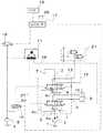
図1は油圧ショベルの斜視図、図2は図1の油圧ショベルに装着された破砕機の一部を破断して示す図である。<Work machine>
First, a working machine provided with the hydraulic system of the present invention will be described with reference to FIGS. 1 and 2. A case where the present invention is applied to a hydraulic excavator as a work machine will be described as an example.
FIG. 1 is a perspective view of a hydraulic excavator, and FIG. 2 is a diagram showing a part of a crusher mounted on the hydraulic excavator shown in FIG.
図1に示すように、作業機械は、油圧ショベルをベースとするものであり、クローラ型の走行体101を備え、この走行体101上に旋回体102が旋回可能に設けられている。旋回体102には、前部左側に運転室103が設けられていると共に、その中央部からブーム104が延びている。ブーム104はその両側の所定位置に配設された一対のブームシリンダ105を伸縮させることで起伏される。当該ブーム104の先にはアーム106が回動可能に連結され、このアーム106の先端にはリンク機構108を介して、本来のバケットの代わりにオプションアタッチメントとして破砕機109が装着されている。そして、これらアーム106および破砕機109もまた、そのアームシリンダ107およびアタッチメントシリンダ110の伸縮を受けて回動される。なお、図1に示す油圧ショベルには、これら以外にも、油圧ショベルの機能を発揮するのに必要な機能部品(図示せず)が配設されている。 As shown in FIG. 1, the work machine is based on a hydraulic excavator, and includes a crawler
図2に示すように、破砕機109は、大きく分けてみたとき、基部フレーム120と、この基部フレーム120の先端部に一体的に延設された固定顎122と、基部フレーム120に回動自在に設けられた可動顎124とを備えており、これら固定顎122と可動顎124とは互いに協働して破砕機109の開閉動作を行う。 As shown in FIG. 2, the
可動顎124は破砕機用シリンダ(オプション油圧アクチュエータ)14に連結されており、この破砕機用シリンダ14は基部フレーム120内に配設されている。破砕機用シリンダ14が伸縮されると、可動顎124は回動軸126を中心に回動し、破砕機109の開閉動作が実施される。 The
<第1の実施形態>
次に、本発明の作業機械の油圧システムの第1の実施形態を、図3乃至図8を用いて説明する。
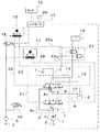
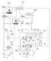
図3は本発明の作業機械の油圧システムの第1の実施形態の概略を示す構成図、図4はオプションアタッチメント未装着時における本発明の作業機械の油圧システムの第1の実施形態における回路構成の概略を示す構成図、図5は本発明の第1の実施形態におけるコントローラの指令電流値と予備流量・方向制御弁に入力される制御パイロット圧力との関係の一例を示す図、図6は本発明の第1の実施形態における流量・方向制御弁の開口面積特性の一例を示す図、図7はオプションアタッチメント装着時における本発明の作業機械の油圧システムの第1の実施形態における回路構成の概略を示す構成図、図8はオプションアタッチメント装着時における本発明の作業機械の油圧システムの第1の実施形態における回路構成の概略を示す構成図である。<First Embodiment>
Next, a first embodiment of a hydraulic system for a work machine according to the present invention will be described with reference to FIGS.
FIG. 3 is a block diagram showing an outline of the first embodiment of the hydraulic system for the work machine according to the present invention. FIG. 4 is a circuit configuration of the hydraulic system for the work machine according to the first embodiment when the optional attachment is not installed. FIG. 5 is a diagram showing an example of the relationship between the command current value of the controller and the control pilot pressure input to the preliminary flow rate / direction control valve in the first embodiment of the present invention, and FIG. FIG. 7 is a diagram showing an example of an opening area characteristic of a flow rate / direction control valve according to the first embodiment of the present invention. FIG. 7 is a circuit configuration of the hydraulic system for a working machine according to the first embodiment of the present invention when an optional attachment is mounted. FIG. 8 is a configuration diagram showing an outline, and FIG. 8 is a configuration showing an outline of a circuit configuration in the first embodiment of the hydraulic system for the working machine of the present invention when the option attachment is mounted It is.
なお、図3の実線はポンプより吐出された油路、破線はパイロット圧の油路、一点破線は圧油の流量・方向を制御するバルブを表し、二点破線はコントローラの信号経路を表す。以下、図4,図7,図8,図9,図10,図11,図12も同様である。 3 represents the oil passage discharged from the pump, the broken line represents the pilot pressure oil passage, the one-dot broken line represents the valve for controlling the flow rate and direction of the pressure oil, and the two-dot broken line represents the signal path of the controller. The same applies to FIGS. 4, 7, 8, 9, 10, 11, and 12.
図3において、作業機械の油圧システムは、油圧ポンプ1、パイロットポンプ5、油圧ポンプ1から吐出される圧油によって駆動される油圧アクチュエータ6およびオプション油圧アクチュエータ14とを有する。 In FIG. 3, the hydraulic system of the work machine includes a
油圧ポンプ1は、エンジンによって駆動される可変容量型の油圧ポンプ(メインポンプ)である。この油圧ポンプ1およびパイロットポンプ5は、エンジンにより回転駆動され、作動油を吐出する。 The
また、図3に示す油圧システムは、油圧ポンプ1から油圧アクチュエータ6やオプション油圧アクチュエータ14に供給される圧油の流れ(方向と流量)を制御し、油圧アクチュエータ6やオプション油圧アクチュエータ14の駆動を制御するコントロールバルブ2を備えている。 3 controls the flow (direction and flow rate) of the pressure oil supplied from the
このコントロールバルブ2は、油圧ポンプ1から油圧アクチュエータ6に供給される圧油の流量および方向を制御する流量・方向制御弁7と、油圧ポンプ1からオプション油圧アクチュエータ14に供給される圧油の流量および方向を制御する予備流量・方向制御弁8とを内蔵している。このコントロールバルブ2は、レバー操作式のアクチュエータ操作レバー11やオプション油圧アクチュエータ操作レバー15からのパイロット圧油に応じてそれらの方向・流量制御弁7,8を駆動することで、油圧アクチュエータ6やオプション油圧アクチュエータ14に供給される圧油の方向と流量を制御する。 The
流量・方向制御弁7および予備流量・方向制御弁8はセンターバイパス型の流量・方向制御弁であり、センターバイパスライン3上に配置されている。すなわち、センターバイパスライン3は流量・方向制御弁7および予備流量・方向制御弁8を貫通して伸びている。センターバイパスライン3の上流側は油圧ポンプ1に接続され、下流側はタンクTに接続されている。また、流量・方向制御弁7および予備流量・方向制御弁8は、油圧パラレルライン4bを介してセンターバイパスライン3にパラレルにも接続されている。 The flow rate /
流量・方向制御弁7は、中立位置では、第1アクチュエータライン9,10をブロックし、油圧ポンプ1から吐出される圧油をタンクTに還流させる。油圧アクチュエータ6を作動させるときは、センターバイパスライン3をブロックするとともに、第1アクチュエータライン9,10のいずれかを油圧入力ライン4aに接続することによって油圧ポンプ1から吐出される圧油を油圧アクチュエータ6のボトム側シリンダ室またはロッド側シリンダ室に供給するとともに、第1アクチュエータライン9,10のもう一方をタンクTに接続することで、ボトム側シリンダ室またはロッド側シリンダ室のもう一方から排出された圧油をタンクTに戻すよう構成されている。 In the neutral position, the flow rate /
予備流量・方向制御弁8は、中立位置では、第2アクチュエータライン12,13をブロックし、油圧ポンプ1から吐出される圧油をタンクTに還流させる。オプション油圧アクチュエータ14を作動させるときは、センターバイパスライン3をブロックするとともに、第2アクチュエータライン12,13のいずれかを油圧入力ライン4cに接続することによって油圧ポンプ1から吐出される圧油をオプション油圧アクチュエータ14のボトム側シリンダ室またはロッド側シリンダ室に供給するとともに、第2アクチュエータライン12,13のもう一方をタンクTに接続することで、ボトム側シリンダ室またはロッド側シリンダ室のもう一方から排出された圧油をタンクTに戻すよう構成されている。 The preliminary flow rate /
油圧アクチュエータ6は、油圧ショベルのフロントを上下(または押し引き)させるための油圧ポンプ1の吐出油により駆動される複動式の片ロッドシリンダであり、図1に示すブームシリンダ105,アームシリンダ107等の総称である。油圧アクチュエータ6や流量・方向制御弁7は、実際は複数あるが、図3では図示の都合上1つだけ示す。 The
油圧アクチュエータ6は、ロッド側とボトム側との2つのシリンダ室を有しており、ボトム側シリンダ室が第1アクチュエータライン9を介して流量・方向制御弁7に接続され、ロッド側シリンダ室が第1アクチュエータライン10を介して流量・方向制御弁7に接続されている。 The
アクチュエータ操作レバー11は、パイロットポンプ5からの圧油をレバー操作量に応じて減圧する減圧弁を内蔵しており、レバー操作量に応じたパイロット圧油をパイロット油路27,28を介して流量・方向制御弁7に対して出力する。これにより油圧アクチュエータ6には流量・方向制御弁7を介して油圧ポンプ1の吐出油が供給される。 The
オプション油圧アクチュエータ14は、通常は使用されないが、図2に示すような破砕機109やレーカや小割などのオプションアタッチメントを駆動させる時に使用されるシリンダである。このオプション油圧アクチュエータ14も、ロッド側とボトム側との2つのシリンダ室を有しており、ロッド側シリンダ室が第2アクチュエータライン12を介して予備流量・方向制御弁8に接続され、ボトム側シリンダ室が第2アクチュエータライン13を介して予備流量・方向制御弁8に接続されている。 The optional
オプション油圧アクチュエータ操作レバー15は、パイロットポンプ5からの圧力をレバー操作量に応じて減圧する減圧弁を内蔵しており、レバー操作量に応じたパイロット圧油をパイロット油路22,23を介して予備流量・方向制御弁8に対して出力する。 The optional hydraulic
パイロット油路22には、オプション油圧アクチュエータ操作レバー15のレバー操作量に応じたパイロット圧油と、コントローラ17からの指令電流で電磁弁16によって減圧されたパイロット油路30のパイロット圧油とのパイロット圧油のいずれかを選択して予備流量・方向制御弁8の一方の受圧部に供給するためのシャトル弁20が設けられている。 The
また、オプション油圧アクチュエータ操作レバー15が操作された場合に、
パイロット油路22,23に出力されたパイロット圧油のいずれかを選択してオプション油圧アクチュエータ圧油カットバルブ21に対して供給するためのパイロット油路22,23から分岐した油路22a,23aを有している。When the optional hydraulic
オプション油圧アクチュエータ圧油カットバルブ21は、第2アクチュエータライン12,13の圧油の流れをカットするよう配置されており、オプション油圧アクチュエータ操作レバー15が操作された際には、オプション油圧アクチュエータ圧油カットバルブ21が開位置となり、オプション油圧アクチュエータ14には予備流量・方向制御弁8を介して油圧ポンプ1の吐出油が供給されるよう構成されている。 The optional hydraulic actuator pressure oil cut
これにより、通常はオプション油圧アクチュエータ圧油カットバルブ21が閉位置であるため、第2アクチュエータライン12,13の圧油の流れがカットされている、すなわちオプション油圧アクチュエータ14に圧油が供給されない状態となる。これに対し、オプション油圧アクチュエータ操作レバー15が操作された際には、オプション油圧アクチュエータ圧油カットバルブ21が開位置となり、オプション油圧アクチュエータ14には予備流量・方向制御弁8を介して油圧ポンプ1の吐出油が供給される。 Accordingly, since the optional hydraulic actuator pressure oil cut
電磁弁18は、オプションアタッチメントが装着されていない場合や、オプションアタッチメントが装着されていても作動させない場合に、コントローラ17からの指令電流の値に応じてオプション油圧アクチュエータ操作レバー15への圧油をカットするよう構成されたオプションアタッチメント操作用のパイロット圧カット用の電磁弁である。 The
同様に、電磁弁16は、オプションアタッチメントが装着されていない場合や、オプションアタッチメントが装着されていても作動させない場合に、予備流量・方向制御弁8をセンターバイパスカット弁として作動させるために、コントローラ17からの指令電流の値に応じてその開口面積が制御されて、パイロットポンプ5から吐出された圧油を減圧したうえでパイロット油路30、シャトル弁20を介してパイロット油路22に供給して予備流量・方向制御弁8の一方の受圧部に供給するよう構成された予備流量・方向制御弁駆動用の電磁弁である。 Similarly, the
コントローラ17は、破砕機109等のオプションアタッチメントが装着されていない場合に、オプションアタッチメントを動作させないときに予備流量・方向制御弁8をセンターバイパスカット弁として作動させるための制御を行う。また、コントローラ17は、破砕機109等のオプションアタッチメントが装着されている際に、オプションアタッチメントを動作させるか否かのスイッチ26における指令に基づいて、オプションアタッチメントを動作させるときには予備流量・方向制御弁8をオプション油圧アクチュエータ14に供給する圧油の流れを制御するバルブとして作動させ、オプションアタッチメントを動作させないときには予備流量・方向制御弁8をセンターバイパスカット弁として作動させる切替制御を行う。 When an optional attachment such as the
スイッチ26は、上述のように、オプションアタッチメントを動作させるときに予備流量・方向制御弁8をオプション油圧アクチュエータ14に供給する圧油の流れを制御するバルブとして作動させ、オプションアタッチメントを動作させないときに予備流量・方向制御弁8をセンターバイパスカット弁として作動させることを切り替えるためのスイッチであり、運転室103に設けられている。 As described above, the
モニタ19は、油圧ショベルに破砕機109等オプションアタッチメントが現在装着されているか否かを選択する選択画面を表示し、いずれかを選択することが可能なように構成されている。また、モニタ19は、現在予備流量・方向制御弁8がオプション油圧アクチュエータ14に圧油を供給する機能か、センターバイパスカット弁の機能のいずれの機能が働いているかを表示するための画面を表示する。 The
〜動作〜
次に、上述した第1の実施形態の作業機械の油圧システムの動作を、図4乃至図8を用いて説明する。~ Operation ~
Next, the operation of the hydraulic system for the work machine according to the first embodiment will be described with reference to FIGS.
〜オプションアタッチメント未装着〜
図4は、オプションアタッチメントが装着されていない場合の本実施形態の作業機械の油圧システムの回路構成の概略を示した図である。~ Optional attachment not installed ~
FIG. 4 is a diagram showing an outline of a circuit configuration of the hydraulic system of the working machine according to the present embodiment when the option attachment is not attached.
図1に示すような油圧ショベルにおいて、オプションアタッチメントではなくバケットが装着されているモードが選択されていることをモニタ19の選択部等により選択されると、コントローラ17は、図4に示すように、指令電流を電磁弁18に対して出力し、電磁弁18は全閉する。電磁弁18が全閉すると、オプション油圧アクチュエータ操作レバー15へ圧油が供給されない。そのため、オプション油圧アクチュエータ操作レバー15が万が一操作されても、パイロット油路22およびパイロット油路23には圧力がたたない。従って、オプション油圧アクチュエータ圧油カットバルブ21が閉位置のままとなり、第2アクチュエータライン12,13に対して圧油が供給されない状態となる。 In the hydraulic excavator as shown in FIG. 1, when the selection unit of the
また、コントローラ17は、アクチュエータ操作レバー11の操作量に応じた指令電流を電磁弁16に対して出力する。電磁弁16は、この指令電流の入力によりその開口面積が制御される。この際のコントローラ17の指令電流とパイロット圧との特性を図5に示す。そのため、パイロットポンプ5から吐出され、電磁弁16によって減圧されたパイロット圧油がパイロット油路30,22を介して予備流量・方向制御弁8の一方の受圧部に供給され、センターバイパスライン3をブロックするように作動し、予備流量・方向制御弁8のセンターバイパスライン3における開口面積が制御される。このときの予備流量・方向制御弁8のセンターバイパスライン3の開口面積は、電磁弁16を通過する制御パイロット圧力に対して、図6のように変化する。 Further, the
従って、運転室103にいるオペレータがアクチュエータ操作レバー11を操作すると、アクチュエータ操作レバー11の操作量に応じて流量・方向制御弁7が作動し、油圧ポンプ1から吐出された圧油が油圧アクチュエータ6に供給される。また、パイロットポンプ5から吐出され、コントローラ17からの指令電流の値に応じて電磁弁16が減圧することで生成されたパイロット圧油がパイロット油路30、シャトル弁20を介してパイロット油路22に供給されて予備流量・方向制御弁8に入力されて予備流量・方向制御弁8が作動し、油圧ポンプ1が吐出した圧油のセンターバイパスライン3を介してタンクTへ向かう油路に対する開口は、流量・方向制御弁7・8の合成開口面積になり、流量・方向制御弁7が単独で作動した時より狭くなるよう制御される。 Therefore, when the operator in the
従って、運転室103にいるオペレータがアクチュエータ操作レバー11を操作すると、アクチュエータ操作レバー11の操作量に応じて流量・方向制御弁7が作動し、アクチュエータが作動する。 Therefore, when the operator in the
〜オプションアタッチメント装着・未使用〜
図7は、オプションアタッチメントが装着されているものの、スイッチ26によってオプションアタッチメントを使用しないモードが選択されている場合の本実施形態の作業機械の油圧システムの回路構成の概略を示した図である。~ Option attachment installed / unused ~
FIG. 7 is a diagram showing an outline of a circuit configuration of the hydraulic system of the working machine of the present embodiment when the option attachment is not used by the
図1に示すような油圧ショベルにおいて、バケットではなくオプションアタッチメントが装着されているモードが選択されていることをモニタ19の選択部により選択され、かつスイッチ26においてオプションアタッチメントを使用しないことが選択されたときは、上述したオプションアタッチメント未装着時と同様に、コントローラ17は、指令電流を電磁弁18に対して出力し、電磁弁18は全閉する。このため、図7に示すように、図4に示した状態と概略同じ回路構成になる。 In the hydraulic excavator as shown in FIG. 1, it is selected by the selection unit of the
また、コントローラ17は、オプションアタッチメント未装着と同様に、アクチュエータ操作レバー11の操作量に応じた指令電流を電磁弁16に対して出力し、電磁弁16は、この指令電流の入力によりその開口面積が制御され、予備流量・方向制御弁8のセンターバイパスの開口面積も制御される。 Further, the
〜オプションアタッチメント装着・使用〜
図8は、オプションアタッチメントが装着されており、かつスイッチ26によってオプションアタッチメントを使用するモードが選択されている場合の本実施形態の作業機械の油圧システムの回路構成の概略を示した図である。~ Installation and use of optional attachments ~
FIG. 8 is a diagram showing an outline of a circuit configuration of the hydraulic system of the working machine according to the present embodiment when the option attachment is mounted and the mode for using the option attachment is selected by the
図1に示すような油圧ショベルにおいて、バケットではなくオプションアタッチメントが装着されているモードが選択されていることをモニタ19の選択部により選択され、かつスイッチ26においてオプションアタッチメントを使用することが選択されたときは、コントローラ17は、図8に示すように、電磁弁18および電磁弁16のいずれに対しても指令電流は出力しない。 In the hydraulic excavator as shown in FIG. 1, it is selected by the selection unit of the
このため、アクチュエータ操作レバー11が操作されると、アクチュエータ操作レバー11の操作量に応じて流量・方向制御弁7が作動し、油圧ポンプ1から吐出された圧油が油圧アクチュエータ6に供給される。 For this reason, when the
また、電磁弁18が開いているため、パイロットポンプ5から吐出された圧油がオプション油圧アクチュエータ操作レバー15へ供給される。そのため、オプション油圧アクチュエータ操作レバー15が操作されると、パイロット油路22またはパイロット油路23に圧力がたち、オプション油圧アクチュエータ圧油カットバルブ21がパイロット油路22またはパイロット油路23の圧力に応じて開いた状態となり、第2アクチュエータライン12,13へ圧油が供給され、オプション油圧アクチュエータ14へ圧油が供給可能な状態となる。 Further, since the
更に、電磁弁16が閉位置のままとなるため、パイロット油路22に供給されたパイロット圧油がシャトル弁20を通過し、予備流量・方向制御弁8の受圧部に供給され、またパイロット油路23に供給されたパイロット圧油は予備流量・方向制御弁8のもう一方の受圧部に供給され、予備流量・方向制御弁8は、オプション油圧アクチュエータ14へ供給する圧油の流量・方向を制御するバルブとして作動する。 Further, since the
従って、オプション油圧アクチュエータ操作レバー15が操作されると、オプションアクチュエータ操作レバー15の操作量に応じて予備流量・方向制御弁8が作動し、油圧ポンプ1から吐出された圧油がオプション油圧アクチュエータ14に対しても供給される。 Accordingly, when the optional hydraulic
〜効果〜
上述のように作動する第1の実施形態の作業機械の油圧システムでは、オプションアタッチメント未装着時は、予備流量・方向制御弁8をセンターバイパスカット弁として作動させることが出来る。したがって、例えば、重負荷微速操作作業時において、油圧アクチュエータ6の負荷保持側のシリンダ室に圧油を供給するよう操作された時に予備流量・方向制御弁8をセンターバイパスカット弁として作動させ、油圧ポンプ1の吐出圧力がシリンダの負荷圧よりも高くなるように制御することで、良好な微速操作性を得られるようになる。~effect~
In the hydraulic system of the working machine according to the first embodiment that operates as described above, the preliminary flow rate /
また、オプションアタッチメントが装着されている際には、オプションアタッチメントを使わない時は図7の構成に、使うときは図8の構成に切り替える切替制御を行い、予備流量・方向制御弁8を、センターバイパスの合成開口面積を調整するセンターバイパスカット弁として作動させてアクチュエータに流れる圧油の流量を制御する機能と、オプション油圧アクチュエータ14に圧油を供給するよう作動させる機能を切り替える。 When the optional attachment is installed, switching control is performed to switch to the configuration shown in FIG. 7 when the optional attachment is not used and to the configuration shown in FIG. 8 when the optional attachment is used. A function for controlling the flow rate of the pressure oil flowing through the actuator by operating as a center bypass cut valve for adjusting the synthetic opening area of the bypass and a function for operating the option
従って、オプションアタッチメント装着・未使用時は、オプションアタッチメント未装着時と同様に、予備流量・方向制御弁8をセンターバイパスカット弁として作動させることが出来る。よって、重負荷微速操作作業時において、専用のセンターバイパスカット弁を備えることなく、エネルギーロスを低減して燃費の悪化を防止することができるとともに良好な微速操作性を得られる、との効果を奏することができる。そして、オプションアタッチメント装着・使用時は、予備流量・方向制御弁8を、オプション油圧アクチュエータ14に圧油を供給するよう作動させることができ、オプション油圧アクチュエータ14に流れる圧油の流量を制御し、オプションアタッチメントを操作性良く使用することが可能となる。 Therefore, when the optional attachment is mounted / not used, the preliminary flow rate /
従って、本実施形態の作業機械の油圧システムによれば、オプションアタッチメント装着時であっても、予備流量・方向制御弁8をセンターバイパスの合成開口面積を調整するセンターバイパスカット弁として作動させることが出来、センターバイパスカット弁を搭載するスペース・コストを省くことが出来る。 Therefore, according to the hydraulic system of the working machine of this embodiment, even when the optional attachment is mounted, the preliminary flow rate /
また、コントローラ17は、破砕機109等のオプションアタッチメントが装着されている際に、オプションアタッチメントを動作させるか否かのスイッチ26を備えていることによって、オプションアタッチメントを使用しない際にオプション油圧アクチュエータ操作レバー15を誤って操作してもオプション油圧アクチュエータ14圧油が供給されない、すなわちオプションアタッチメントが動作しないようにすることができ、オペレータの意図しない動作が実行されることを防止することができる。 Further, the
更に、第2アクチュエータライン12,13の圧油の流れをカットするためのカットバルブ21を有していることにより、オプションアタッチメントが装着されている際に、予備流量・方向制御弁8をセンターバイパスカット弁として作動させる際に、オプション油圧アクチュエータ14に圧油が供給されることを確実に防止することができ、オペレータの意図しない動作が実行されることを防止することができる。 Further, by having a
〜他の態様〜
なお、本実施形態の作業機械の油圧システムはこの形態に限られない。以下、本発明の作業機械の油圧システムの第1の実施形態の他の態様の概略を図9を参照して説明する。
図9は本発明の作業機械の油圧システムの第1の実施形態の他の概略を示す構成図である。~ Other aspects ~
In addition, the hydraulic system of the working machine of this embodiment is not restricted to this form. The outline of another aspect of the first embodiment of the hydraulic system for work machines of the present invention will be described below with reference to FIG.
FIG. 9 is a configuration diagram showing another outline of the first embodiment of the hydraulic system for the working machine of the present invention.
図9に示すように、本発明の第1の実施形態の他の態様に係る作業機械の油圧システムは、オプション油圧アクチュエータ圧油カットバルブ21およびパイロット油路22,23から分岐した油路22a,23aを備えていない。 As shown in FIG. 9, the hydraulic system for a work machine according to another aspect of the first embodiment of the present invention includes an
また、図3に示す第1の実施形態の作業機械の油圧システムにおける電磁弁18の代わりに、オプションアタッチメントが装着され、かつ作動させる場合に、コントローラ17からの指令電流の値に応じてオプション油圧アクチュエータ操作レバー15に対して圧油を供給するよう構成された電磁弁18Aを備えている。 Further, in the case where an optional attachment is installed and operated instead of the
その他の構成は、図3に示す作業機械の油圧システムと概略同じである。 Other configurations are substantially the same as the hydraulic system of the work machine shown in FIG.
〜動作〜
次に、上述した第1の実施形態の他の態様の作業機械の油圧システムの動作について説明する。~ Operation ~
Next, the operation of the hydraulic system for the work machine according to another aspect of the first embodiment described above will be described.
〜オプションアタッチメント未装着〜
図1に示すような油圧ショベルにおいて、オプションアタッチメントではなくバケットが装着されているモードが選択されていることをモニタ19の選択部により選択されると、コントローラ17は、アクチュエータ操作レバー11の操作量に応じた指令電流を電磁弁16に対して出力し、この指令電流の入力により電磁弁16の開口面積が制御され、予備流量・方向制御弁8のセンターバイパスの開口面積も制御される。~ Optional attachment not installed ~
In the hydraulic excavator as shown in FIG. 1, when the selection unit of the
これに対し、コントローラ17は、電磁弁18Aに対して指令電流は出力しない。よって、電磁弁18Aは全閉し、オプション油圧アクチュエータ操作レバー15へ圧油が供給されず、パイロット油路22およびパイロット油路23には圧力がたたない。 On the other hand, the
従って、運転室103にいるオペレータがアクチュエータ操作レバー11を操作すると、アクチュエータ操作レバー11の操作量に応じて流量・方向制御弁7が作動し、油圧ポンプ1から吐出された圧油が油圧アクチュエータ6に供給される。この際に、予備流量・方向制御弁8が作動し、油圧ポンプ1が吐出した圧油のセンターバイパスライン3を介してタンクTへ向かう油路に対する開口は、流量・方向制御弁7・8の合成開口面積になり、流量・方向制御弁7が単独で作動した時より狭くなるよう制御される。 Therefore, when the operator in the
〜オプションアタッチメント装着・未使用〜
図1に示すような油圧ショベルにおいて、バケットではなくオプションアタッチメントが装着されているモードが選択されていることをモニタ19の選択部により選択され、かつスイッチ26においてオプションアタッチメントを使用しないことが選択されたときは、コントローラ17は、オプションアタッチメント未装着時と同様に、電磁弁18Aに対しては指令電流を出力せず、電磁弁16に対してアクチュエータ操作レバー11の操作量に応じた指令電流を電磁弁16に対して出力する。従って、オプションアタッチメント未装着と同様の回路構成となり、同様の動作が実施可能となる。~ Option attachment installed / unused ~
In the hydraulic excavator as shown in FIG. 1, it is selected by the selection unit of the
〜オプションアタッチメント装着・使用〜
図1に示すような油圧ショベルにおいて、バケットではなくオプションアタッチメントが装着されているモードが選択されていることをモニタ19の選択部により選択され、かつスイッチ26においてオプションアタッチメントを使用するとされたときは、コントローラ17は、電磁弁16に対しては指令電流を出力せず、電磁弁18Aに対しては指令電流を出力する。~ Installation and use of optional attachments ~
In the hydraulic excavator as shown in FIG. 1, when the selection unit of the
このため、電磁弁18Aが開位置、電磁弁16が閉位置になり、パイロット油路22に供給されたパイロット圧油がシャトル弁20を通過し、予備流量・方向制御弁8の受圧部に供給され、またパイロット油路23に供給されたパイロット圧油は予備流量・方向制御弁8のもう一方の受圧部に供給され、予備流量・方向制御弁8は、オプション油圧アクチュエータ14へ供給する圧油の流量・方向を制御するバルブとして作動する。 Therefore, the
従って、アクチュエータ操作レバー11が操作されると、アクチュエータ操作レバー11の操作量に応じて流量・方向制御弁7が作動し、油圧ポンプ1から吐出された圧油が油圧アクチュエータ6に供給される。また、オプション油圧アクチュエータ操作レバー15が操作されると、オプションアクチュエータ操作レバー15の操作量に応じて予備流量・方向制御弁8が作動し、油圧ポンプ1から吐出された圧油がオプション油圧アクチュエータ14に対して供給され、オプションアタッチメントが作動する。 Therefore, when the
〜効果〜
このように、図9に示すような第1の実施形態の他の態様の作業機械の油圧システムにおいても、図3に示すような第1の実施形態の作業機械の油圧システムと同様の効果が得られる。~effect~
As described above, the hydraulic system for the work machine according to another aspect of the first embodiment as shown in FIG. 9 has the same effect as the hydraulic system for the work machine according to the first embodiment as shown in FIG. can get.
また、本態様では、オプション油圧アクチュエータ圧油カットバルブ21およびパイロット油路22,23から分岐した油路22a,23aを備えていないため、図3に示す作業機械の油圧システムに比べて回路構成が簡単となり、低コストの油圧システムとすることができる。 Further, in this embodiment, since the
なお、上述の実施形態では、スイッチ26が設けられている場合について説明したが、モニタの選択部においてモニタ19にて現在予備流量・方向制御弁8がオプション油圧アクチュエータ14に圧油を供給する機能か、センターバイパスカット弁の機能のいずれかの機能の切り替えを指示することが出来るようにすることができる。 In the above-described embodiment, the case where the
<第2の実施形態>
本発明の作業機械の油圧システムの第2の実施形態を図10および図11を用いて説明する。
図10は本発明の作業機械の油圧システムの第2の実施形態の概略を示す構成図である。<Second Embodiment>
A second embodiment of the hydraulic system for work machines of the present invention will be described with reference to FIGS. 10 and 11.
FIG. 10 is a configuration diagram showing an outline of a second embodiment of the hydraulic system for the working machine according to the present invention.
図10に示すように、本発明の第2の実施形態に係る作業機械の油圧システムは、図3に示す第1の実施形態の作業機械の油圧システムにおけるスイッチ26およびモニタ19の替わりに、パイロット油路22,23に出力されたパイロット圧油のいずれかを選択するシャトル弁21aを通過してオプション油圧アクチュエータ圧油カットバルブ21に対して圧油を供給するための油路21bにおけるパイロット圧油の大きさを検知するための圧力センサ24を備えている。 As shown in FIG. 10, the working machine hydraulic system according to the second embodiment of the present invention is a pilot instead of the
また、コントローラ17は、圧力センサ24の検出信号に基づいて、電磁弁16に対して指令電流を出力する。 Further, the
また、コントローラ17からの指令電流の値に応じてオプション油圧アクチュエータ操作レバー15へ圧油を供給する油路に設けられた電磁弁18を備えていない。 Further, the
その他の構成は、図3に示す作業機械の油圧システムと概略同じである。 Other configurations are substantially the same as the hydraulic system of the work machine shown in FIG.
〜動作〜
次に、上述した第2の実施形態の作業機械の油圧システムの動作について説明する。~ Operation ~
Next, the operation of the hydraulic system for the work machine according to the second embodiment will be described.
〜オプションアタッチメント未装着〜
図1に示すような油圧ショベルにおいて、オプションアタッチメントではなくバケットが装着されているモードが選択されると、コントローラ17は、アクチュエータ操作レバー11の操作量に応じた指令電流を電磁弁16に対して出力し、この指令電流の入力により電磁弁16の開口面積が制御され、予備流量・方向制御弁8のセンターバイパスの開口面積も制御される。また、オプションアクチュエータが装着されていないことから通常はオプション油圧アクチュエータ操作レバー15は操作されないため、パイロット油路22およびパイロット油路23には圧力がたたず、オプション油圧アクチュエータ圧油カットバルブ21が閉位置のままとなり、第2アクチュエータライン12,13に対して圧油が供給されることが抑止される。~ Optional attachment not installed ~
In the hydraulic excavator as shown in FIG. 1, when a mode in which a bucket is mounted instead of an optional attachment is selected, the
従って、運転室103にいるオペレータがアクチュエータ操作レバー11を操作すると、アクチュエータ操作レバー11の操作量に応じて流量・方向制御弁7が作動し、油圧ポンプ1から吐出された圧油が油圧アクチュエータ6に供給される。この際に、予備流量・方向制御弁8が作動し、油圧ポンプ1が吐出した圧油のセンターバイパスライン3を介してタンクTへ向かう油路に対する開口は、流量・方向制御弁7・8の合成開口面積になり、流量・方向制御弁7が単独で作動した時より狭くなるよう制御される。 Therefore, when the operator in the
〜オプションアタッチメント装着・未使用〜
図1に示すような油圧ショベルにおいて、バケットではなくオプションアタッチメントが装着されているモードが選択されると、コントローラ17は、圧力センサ24の検出値をモニタし続ける。この圧力センサ24の検出値において、オプションアタッチメントが不使用、すなわちオプション油圧アクチュエータ操作レバー15が操作されず、パイロット油路22,23の何れにもパイロット圧油が出力されていないと判定すると、コントローラ17は、アクチュエータ操作レバー11の操作量に応じた指令電流を電磁弁16に対して出力し、この指令電流の入力により電磁弁16の開口面積が制御され、予備流量・方向制御弁8のセンターバイパスの開口面積も制御される。~ Option attachment installed / unused ~
In the hydraulic excavator as shown in FIG. 1, when the mode in which the option attachment is attached instead of the bucket is selected, the
従って、予備流量・方向制御弁8が作動し、油圧ポンプ1が吐出した圧油のセンターバイパスライン3を介してタンクTへ向かう油路に対する開口は、流量・方向制御弁7・8の合成開口面積になり、流量・方向制御弁7が単独で作動した時より狭くなるよう制御される。 Therefore, the preliminary flow rate /
また、パイロット油路22およびパイロット油路23には圧力がたたないため、オプション油圧アクチュエータ圧油カットバルブ21が閉位置のままとなり、第2アクチュエータライン12,13へ圧油が供給されず、オプション油圧アクチュエータ14に圧油が供給されない状態となる。 Further, since no pressure is applied to the
〜オプションアタッチメント装着・使用〜
オプションアタッチメント装着・未使用の場合と同様に、コントローラ17は、圧力センサ24の検出値をモニタし続ける。この圧力センサ24の検出値において、オプションアタッチメントが使用されている、すなわちオプション油圧アクチュエータ操作レバー15が操作され、パイロット油路22,23の何れかにパイロット圧油が出力されていると判定すると、コントローラ17は、電磁弁16に対して指令電流を出力しない。~ Installation and use of optional attachments ~
The
このため、電磁弁16が閉位置になり、パイロット油路22に供給されたパイロット圧油がシャトル弁20を通過し、予備流量・方向制御弁8の受圧部に供給され、またパイロット油路23に供給されたパイロット圧油は予備流量・方向制御弁8のもう一方の受圧部に供給され、予備流量・方向制御弁8は、オプション油圧アクチュエータ14へ供給する圧油の流量・方向を制御するバルブとして作動し、オプションアタッチメントが作動する。 For this reason, the
〜効果〜
このように、図10に示すような第2の実施形態の作業機械の油圧システムにおいても、予備流量・方向制御弁8が、オプション油圧アクチュエータ14に圧油を供給する機能とセンターバイパスカット弁の機能とが、オプション油圧アクチュエータ操作レバー15の操作によって切り替わり、図3に示すような第1の実施形態の作業機械の油圧システムと同様の効果が得られる。~effect~
Thus, also in the hydraulic system of the working machine of the second embodiment as shown in FIG. 10, the function of the auxiliary flow rate /
また、本実施形態では、圧力センサ24を設けて、予備流量・方向制御弁8の機能をオプション油圧アクチュエータ操作レバー15の操作によって切り替えるため、図3に示すような第1の実施形態の作業機械の油圧システムにおけるスイッチ26や電磁弁18の構成が不要となり、回路構成が簡単となり、より低コストの油圧システムとすることができる。 Further, in this embodiment, the
また、オプション油圧アクチュエータ操作レバー15の操作によって予備流量・方向制御弁8の機能が切り替わるため、第1の実施形態のようにスイッチ26を操作する必要がなく、操作が容易となる。 Further, since the function of the auxiliary flow rate /
〜他の態様〜
なお、本実施形態の作業機械の油圧システムはこの形態に限られない。以下、本発明の作業機械の油圧システムの第2の実施形態の他の態様の概略を図11を参照して説明する。
図11は本発明の作業機械の油圧システムの第2の実施形態の他の概略を示す構成図である。~ Other aspects ~
In addition, the hydraulic system of the working machine of this embodiment is not restricted to this form. The outline of another aspect of the second embodiment of the hydraulic system for work machines of the present invention will be described below with reference to FIG.
FIG. 11 is a block diagram showing another outline of the second embodiment of the hydraulic system for the working machine of the present invention.
図11に示すように、本発明の第2の実施形態の他の態様に係る作業機械の油圧システムは、図9に示す第2の実施形態の作業機械の油圧システムにおいてオプションアタッチメントが装着され、かつ作動させる場合に、コントローラ17からの指令電流の値に応じてオプション油圧アクチュエータ操作レバー15へ圧油を供給するよう構成された電磁弁18Aを備えている。 As shown in FIG. 11, the work machine hydraulic system according to another aspect of the second embodiment of the present invention is equipped with an option attachment in the work machine hydraulic system of the second embodiment shown in FIG. 9, In addition, an
また、オプション油圧アクチュエータ圧油カットバルブ21を備えていない。 Further, the optional hydraulic actuator pressure oil cut
その他の構成は、図10に示す作業機械の油圧システムと概略同じである。 Other configurations are substantially the same as the hydraulic system of the working machine shown in FIG.
〜動作〜
次に、上述した第2の実施形態の他の態様の作業機械の油圧システムの動作について説明する。~ Operation ~
Next, the operation of the hydraulic system for a work machine according to another aspect of the second embodiment described above will be described.
〜オプションアタッチメント未装着〜
図1に示すような油圧ショベルにおいて、オプションアタッチメントではなくバケットが装着されているモードが選択されると、コントローラ17は、アクチュエータ操作レバー11の操作量に応じた指令電流を電磁弁16に対して出力し、この指令電流の入力により電磁弁16の開口面積が制御され、予備流量・方向制御弁8のセンターバイパスの開口面積も制御される。~ Optional attachment not installed ~
In the hydraulic excavator as shown in FIG. 1, when a mode in which a bucket is mounted instead of an optional attachment is selected, the
また、コントローラ17は、電磁弁18Aに対して指令電流は出力しない。よって、電磁弁18Aが全閉し、オプション油圧アクチュエータ操作レバー15へ圧油が供給されず、パイロット油路22およびパイロット油路23には圧力がたたない。 Further, the
従って、運転室103にいるオペレータがアクチュエータ操作レバー11を操作すると、アクチュエータ操作レバー11の操作量に応じて流量・方向制御弁7が作動し、油圧ポンプ1から吐出された圧油が油圧アクチュエータ6に供給される。この際に、予備流量・方向制御弁8が作動し、油圧ポンプ1が吐出した圧油のセンターバイパスライン3を介してタンクTへ向かう油路に対する開口は、流量・方向制御弁7・8の合成開口面積になり、流量・方向制御弁7が単独で作動した時より狭くなるよう制御される。 Therefore, when the operator in the
〜オプションアタッチメント装着・未使用〜
図1に示すような油圧ショベルにおいて、バケットではなくオプションアタッチメントが装着されているモードが選択されると、コントローラ17は、電磁弁18Aに対して指令電流を出力する。また、コントローラ17は、圧力センサ24の検出値をモニタし続ける。この圧力センサ24の検出値において、オプションアタッチメントが使用されていない、すなわちオプション油圧アクチュエータ操作レバー15が操作されず、パイロット油路22,23の何れにもパイロット圧油が出力されていないと判定すると、コントローラ17は、アクチュエータ操作レバー11の操作量に応じた指令電流を電磁弁16に対して出力する。~ Option attachment installed / unused ~
In the hydraulic excavator as shown in FIG. 1, when a mode in which an option attachment is mounted instead of a bucket is selected, the
従って、予備流量・方向制御弁8が作動し、油圧ポンプ1が吐出した圧油のセンターバイパスライン3を介してタンクTへ向かう油路に対する開口は、流量・方向制御弁7・8の合成開口面積になり、流量・方向制御弁7が単独で作動した時より狭くなるよう制御される。 Therefore, the preliminary flow rate /
〜オプションアタッチメント装着・使用〜
オプションアタッチメント装着・未使用の場合と同様に、コントローラ17は、電磁弁18Aに対して指令電流を出力するとともに、圧力センサ24の検出値をモニタし続ける。この圧力センサ24の検出値において、オプションアタッチメントが使用されていると判定すると、コントローラ17は、電磁弁16に対して指令電流を出力しない。~ Installation and use of optional attachments ~
Similarly to the case where the option attachment is mounted / not used, the
このため、電磁弁16が閉位置になり、パイロット油路22に供給されたパイロット圧油がシャトル弁20を通過し、予備流量・方向制御弁8の受圧部に供給され、またパイロット油路23に供給されたパイロット圧油は予備流量・方向制御弁8のもう一方の受圧部に供給され、予備流量・方向制御弁8は、オプション油圧アクチュエータ14へ供給する圧油の流量・方向を制御するバルブとして作動し、オプションアタッチメントが作動する。 For this reason, the
〜効果〜
このように、図11に示すような第2の実施形態の他の態様の作業機械の油圧システムにおいても、図10に示すような第2の実施形態の作業機械の油圧システムと同様の効果が得られる。~effect~
As described above, the working machine hydraulic system of another aspect of the second embodiment as shown in FIG. 11 has the same effect as the hydraulic system of the working machine of the second embodiment as shown in FIG. can get.
また、本態様では、オプション油圧アクチュエータ圧油カットバルブ21を備えていないため、図10に示す作業機械の油圧システムに比べて回路構成が簡単となり、より低コストの油圧システムとすることができる。 Further, in this aspect, since the optional hydraulic actuator pressure oil cut
<第3の実施形態>
本発明の作業機械の油圧システムの第3の実施形態を図12を用いて説明する。
図12は本発明の作業機械の油圧システムの第3の実施形態の概略を示す構成図である。<Third Embodiment>
A third embodiment of the hydraulic system for work machines according to the present invention will be described with reference to FIG.
FIG. 12 is a configuration diagram showing an outline of the third embodiment of the hydraulic system for the working machine according to the present invention.
図12に示すように、本発明の作業機械の油圧システムの第3の実施形態は、油圧ポンプ1からオプション油圧アクチュエータ14に供給される圧油の流量および方向を制御する予備流量・方向制御弁8の替わりに、予備流量・方向制御弁8Aが設けられている。 As shown in FIG. 12, the third embodiment of the hydraulic system for work machines according to the present invention is a preliminary flow rate / direction control valve that controls the flow rate and direction of the pressure oil supplied from the
この予備流量・方向制御弁8Aは、中立位置では、第2アクチュエータライン12,13をブロックし、油圧ポンプ1から吐出される圧油をタンクTに還流させる。予備流量・方向制御弁8Aをセンターバイパスカット弁として作動させるときは、センターバイパスライン3,第2アクチュエータライン12,13のいずれもブロックするよう構成されている。更に、オプション油圧アクチュエータ14を作動させるときは、センターバイパスライン3をブロックするとともに、第2アクチュエータライン13を油圧入力ライン4cに接続することによって油圧ポンプ1から吐出される圧油をオプション油圧アクチュエータ14のロッド側シリンダ室に供給するとともに、第2アクチュエータライン12をタンクTに接続することで、オプション油圧アクチュエータ14のボトム側シリンダ室から排出された圧油をタンクTに戻すよう構成されている。 In the neutral position, the preliminary flow rate / direction control valve 8A blocks the
また、オプション油圧アクチュエータ操作レバー15が操作された場合に、
予備流量・方向制御弁8Aを流量・方向制御弁として作動させるようオプション油圧アクチュエータ操作レバー15から出力されたパイロット圧油を予備流量・方向制御弁8の一方の受圧室に入力するパイロット油路31を有している。When the optional hydraulic
予備流量・方向制御弁8Aのもう一方の受圧室には、予備流量・方向制御弁8Aをセンターバイパスカット弁として作動させるために、コントローラ17からの指令電流の値に応じて電磁弁16Aによって減圧されたパイロット圧油を入力するためのパイロット油路32が接続されている。 The other pressure receiving chamber of the preliminary flow / direction control valve 8A is depressurized by the
更に、パイロット油路31のパイロット圧油の大きさを検知するための圧力センサ25を備えている。また、コントローラ17は、圧力センサ25の検出信号に基づいて、電磁弁16Aに対して指令電流を出力する。 Further, a
その他の構成は、図3に示す作業機械の油圧システムと概略同じである。 Other configurations are substantially the same as the hydraulic system of the work machine shown in FIG.
〜動作〜
次に、上述した第3の実施形態の作業機械の油圧システムの動作について説明する。~ Operation ~
Next, the operation of the hydraulic system for the work machine according to the third embodiment described above will be described.
〜オプションアタッチメント未装着〜
図1に示すような油圧ショベルにおいて、オプションアタッチメントではなくバケットが装着されているモードが選択されると、コントローラ17は、アクチュエータ操作レバー11の操作量に応じた指令電流を電磁弁16Aに対して出力し、この指令電流の入力により電磁弁16Aの開口面積が制御され、パイロットポンプ5から吐出され、電磁弁16Aによって減圧されたパイロット圧油がパイロット油路32を介して予備流量・方向制御弁8Aの一方の受圧部に供給される。よって予備流量・方向制御弁8Aのセンターバイパスの開口面積が制御され(第2位置)、油圧ポンプ1が吐出した圧油のセンターバイパスライン3を介してタンクTへ向かう油路に対する開口は、流量・方向制御弁7・8Aの合成開口面積になり、流量・方向制御弁7が単独で作動した時より狭くなるよう制御される。~ Optional attachment not installed ~
In the hydraulic excavator as shown in FIG. 1, when a mode in which a bucket is mounted instead of an optional attachment is selected, the
〜オプションアタッチメント装着・未使用〜
図1に示すような油圧ショベルにおいて、バケットではなくオプションアタッチメントが装着されているモードが選択されると、コントローラ17は、圧力センサ25の検出値をモニタし続ける。この圧力センサ25の検出値において、オプション油圧アクチュエータ14が使用されていないと判定すると、コントローラ17は、アクチュエータ操作レバー11の操作量に応じた指令電流を電磁弁16Aに対して出力する。これにより、予備流量・方向制御弁8Aのセンターバイパスの開口面積が制御され(第2位置)、油圧ポンプ1が吐出した圧油のセンターバイパスライン3を介してタンクTへ向かう油路に対する開口は、流量・方向制御弁7・8Aの合成開口面積になり、流量・方向制御弁7が単独で作動した時より狭くなるよう制御される。~ Option attachment installed / unused ~
In the hydraulic excavator as shown in FIG. 1, when the mode in which the option attachment is attached instead of the bucket is selected, the
〜オプションアタッチメント装着・使用〜
同様に、コントローラ17は、圧力センサ25の検出値をモニタし続ける。この圧力センサ25の検出値において、オプションアタッチメントが使用されている、すなわちオプション油圧アクチュエータ操作レバー15が操作され、パイロット油路31にパイロット圧油が出力されていると判定すると、コントローラ17は、電磁弁16Aに対して指令電流を出力しない。~ Installation and use of optional attachments ~
Similarly, the
このため、電磁弁16Aが閉位置になり、パイロット油路31にパイロット圧油が供給されず、予備流量・方向制御弁8Aは、オプション油圧アクチュエータ操作レバー15の操作量に応じたパイロット圧油がパイロット油路31を介して受圧部に供給され、オプション油圧アクチュエータ14を作動させる流量・方向制御弁として作動する(第1位置)。 For this reason, the
〜効果〜
このように、図12に示すような第3の実施形態の作業機械の油圧システムにおいても、予備流量・方向制御弁8Aが、オプション油圧アクチュエータ14に圧油を供給する機能とセンターバイパスカット弁の機能とが、オプション油圧アクチュエータ操作レバー15の操作によって切り替わり、図3に示すような第1の実施形態,図9に示すような第2の実施形態の作業機械の油圧システムと同様の効果が得られる。~effect~
Thus, also in the hydraulic system of the working machine of the third embodiment as shown in FIG. 12, the auxiliary flow rate / direction control valve 8A has a function of supplying pressure oil to the optional
また、本実施形態は、圧油がオプション油圧アクチュエータ14のロッド側シリンダ室にのみ供給される態様に好適な油圧システムとなる。 Further, the present embodiment is a hydraulic system suitable for a mode in which pressure oil is supplied only to the rod side cylinder chamber of the optional
<その他>
なお、本発明は上記の実施形態に限られず、種々の変形、応用が可能なものである。<Others>
In addition, this invention is not restricted to said embodiment, A various deformation | transformation and application are possible.
例えば、作業機械の例として油圧ショベルを用いて説明したが、本発明における作業機械は油圧ショベルに限られない。 For example, although a hydraulic excavator has been described as an example of a working machine, the working machine in the present invention is not limited to a hydraulic excavator.
1…油圧ポンプ、
2…コントロールバルブ、
3…センターバイパスライン、
4…油圧パラレルライン、
5…パイロットポンプ、
6…油圧アクチュエータ、
7…流量・方向制御弁、
8,8A…予備流量・方向制御弁、
9…第1アクチュエータライン、
10…第1アクチュエータライン、
11…アクチュエータ操作レバー、
12…第2アクチュエータライン、
13…第2アクチュエータライン、
14…オプション油圧アクチュエータ、
15…オプション油圧アクチュエータ操作レバー、
16…電磁弁、
17…コントローラ、
18,18A…電磁弁、
19…状態表示装置(モニタ)、
20,21a…シャトル弁、
21…オプション油圧アクチュエータ圧油カットバルブ、
21b,22,23,27,28,30,31,32…パイロット油路、
22a,23a…油路、
24,25…圧力センサ、
26…スイッチ、
101…走行体、
102…旋回体、
103…運転室、
104…ブーム、
105…ブームシリンダ、
106…アーム、
107…アームシリンダ、
108…リンク機構、
109…破砕機、
110…アタッチメントシリンダ、
120…基部フレーム、
122…固定顎、
124…可動顎、
126…回動軸、
T…タンク。1 ... Hydraulic pump,
2 ... Control valve,
3. Center bypass line,
4 ... Hydraulic parallel line,
5 ... Pilot pump,
6 ... Hydraulic actuator,
7 ... Flow / direction control valve,
8, 8A ... Preliminary flow rate / direction control valve,
9: First actuator line,
10: First actuator line,
11 ... Actuator operation lever,
12 ... Second actuator line,
13 ... Second actuator line,
14 ... Optional hydraulic actuator,
15 ... Optional hydraulic actuator operation lever,
16 ... solenoid valve,
17 ... Controller,
18, 18A ... Solenoid valve,
19 ... Status display device (monitor),
20, 21a ... shuttle valve,
21 ... Optional hydraulic actuator pressure oil cut valve,
21b, 22, 23, 27, 28, 30, 31, 32 ... pilot oil passage,
22a, 23a ... oil passage,
24, 25 ... pressure sensor,
26 ... switch,
101 ... traveling body,
102 ... swivel body,
103 ... driver's cab,
104 ... Boom,
105 ... Boom cylinder,
106 ... arm,
107 ... arm cylinder,
108: Link mechanism,
109 ... Crusher,
110 ... Attachment cylinder,
120 ... base frame,
122 ... fixed jaw,
124 ... movable jaw,
126 ... rotating shaft,
T ... Tank.
Claims (5)
Translated fromJapaneseこの油圧ポンプの吐出油により駆動される油圧アクチュエータと、
前記油圧ポンプから前記油圧アクチュエータに供給される圧油の流れを制御するセンターバイパス型の流量・方向制御弁と、
この流量・方向制御弁を貫通するセンターバイパスラインの前記流量・方向制御弁の下流側の位置に配置された予備流量・方向制御弁であって、オプション油圧アクチュエータの使用時に前記油圧ポンプから前記オプション油圧アクチュエータに供給される圧油の流れを制御するためのセンターバイパス型の予備流量・方向制御弁と、
前記オプション油圧アクチュエータを動作させるときは、前記予備流量・方向制御弁を前記オプション油圧アクチュエータに供給する圧油の流れを制御するバルブとして作動させ、前記オプション油圧アクチュエータを動作させないときは、前記予備流量・方向制御弁をセンターバイパスカット弁として作動させる切替制御装置とを備えることを特徴とする作業機械の油圧システム。A hydraulic pump;
A hydraulic actuator driven by the oil discharged from the hydraulic pump;
A center bypass type flow rate / direction control valve for controlling the flow of pressure oil supplied from the hydraulic pump to the hydraulic actuator;
A preliminary flow rate / direction control valve disposed at a position downstream of the flow rate / direction control valve of the center bypass line that passes through the flow rate / direction control valve, wherein the option is supplied from the hydraulic pump when the optional hydraulic actuator is used. A center bypass type preliminary flow rate / direction control valve for controlling the flow of pressure oil supplied to the hydraulic actuator;
When the optional hydraulic actuator is operated, the preliminary flow rate / direction control valve is operated as a valve for controlling the flow of pressure oil supplied to the optional hydraulic actuator, and when the optional hydraulic actuator is not operated, the preliminary flow rate is controlled. A hydraulic system for a working machine, comprising: a switching control device that operates the direction control valve as a center bypass cut valve.
前記切替制御装置は、前記予備流量・方向制御弁の作動を切り替えるためのスイッチを有することを特徴とする作業機械の油圧システム。The hydraulic system for a work machine according to claim 1,
The hydraulic control system for a working machine, wherein the switching control device includes a switch for switching the operation of the preliminary flow rate / direction control valve.
前記切替制御装置は、前記予備流量・方向制御弁を前記オプション油圧アクチュエータの流量・方向制御弁として作動させない状態にあることを検知するセンサを更に備え、
前記切替制御装置は、このセンサから出力された検知信号を基にして前記予備流量・方向制御弁の作動を切り替える制御を行うことを特徴とする作業機械の油圧システム。The hydraulic system for a work machine according to claim 1,
The switching control device further includes a sensor that detects that the preliminary flow rate / direction control valve is not operated as a flow rate / direction control valve of the optional hydraulic actuator,
The hydraulic control system for a work machine, wherein the switching control device performs control to switch the operation of the preliminary flow rate / direction control valve based on a detection signal output from the sensor.
前記予備流量・方向制御弁から前記オプション油圧アクチュエータに圧油を供給するアクチュエータ油路に配置された開閉バルブを更に備え、
前記切替制御装置は、前記予備流量・方向制御弁をセンターバイパスカット弁として作動させるときに前記開閉バルブを閉じて前記油路を遮断するよう制御することを特徴とする作業機械の油圧システム。In the hydraulic system of the working machine according to claim 2 or 3,
An open / close valve disposed in an actuator oil passage for supplying pressure oil to the optional hydraulic actuator from the preliminary flow rate / direction control valve;
The switching control device controls a hydraulic system for a work machine to close the on-off valve and shut off the oil passage when the auxiliary flow rate / direction control valve is operated as a center bypass cut valve.
前記予備流量・方向制御弁は、前記オプション油圧アクチュエータに圧油を供給する第1位置と、前記オプション油圧アクチュエータへの圧油の供給を遮断する第2位置とに切り換え可能であり、
前記切替制御装置は、前記予備流量・方向制御弁を前記オプション油圧アクチュエータに供給する圧油の流れを制御するバルブとして作動させるとき、前記予備流量・方向制御弁を前記第1位置に切り換え、前記予備流量・方向制御弁をセンターバイパスカット弁として作動させるとき、前記予備流量・方向制御弁を前記第2位置に切り換えるよう制御することを特徴とする作業機械の油圧システム。The hydraulic system for a work machine according to claim 1,
The preliminary flow rate / direction control valve can be switched between a first position for supplying pressure oil to the optional hydraulic actuator and a second position for blocking supply of pressure oil to the optional hydraulic actuator,
The switching control device switches the preliminary flow rate / direction control valve to the first position when operating the preliminary flow rate / direction control valve as a valve for controlling the flow of pressure oil supplied to the optional hydraulic actuator, A hydraulic system for a working machine, wherein when the preliminary flow rate / direction control valve is operated as a center bypass cut valve, the preliminary flow rate / direction control valve is controlled to be switched to the second position.
Priority Applications (6)
| Application Number | Priority Date | Filing Date | Title |
|---|---|---|---|
| JP2014060890AJP6013389B2 (en) | 2014-03-24 | 2014-03-24 | Hydraulic system of work machine |
| CN201580001643.0ACN105518311B (en) | 2014-03-24 | 2015-01-09 | Hydraulic systems for working machines |
| US14/915,311US10253479B2 (en) | 2014-03-24 | 2015-01-09 | Hydraulic system for work machine |
| KR1020167004088AKR101767857B1 (en) | 2014-03-24 | 2015-01-09 | Hydraulic system for work vehicle |
| PCT/JP2015/050455WO2015146219A1 (en) | 2014-03-24 | 2015-01-09 | Hydraulic system for work vehicle |
| EP15770367.9AEP3124798B1 (en) | 2014-03-24 | 2015-01-09 | Hydraulic system for work vehicle |
Applications Claiming Priority (1)
| Application Number | Priority Date | Filing Date | Title |
|---|---|---|---|
| JP2014060890AJP6013389B2 (en) | 2014-03-24 | 2014-03-24 | Hydraulic system of work machine |
Publications (2)
| Publication Number | Publication Date |
|---|---|
| JP2015183776A JP2015183776A (en) | 2015-10-22 |
| JP6013389B2true JP6013389B2 (en) | 2016-10-25 |
Family
ID=54194762
Family Applications (1)
| Application Number | Title | Priority Date | Filing Date |
|---|---|---|---|
| JP2014060890AActiveJP6013389B2 (en) | 2014-03-24 | 2014-03-24 | Hydraulic system of work machine |
Country Status (6)
| Country | Link |
|---|---|
| US (1) | US10253479B2 (en) |
| EP (1) | EP3124798B1 (en) |
| JP (1) | JP6013389B2 (en) |
| KR (1) | KR101767857B1 (en) |
| CN (1) | CN105518311B (en) |
| WO (1) | WO2015146219A1 (en) |
Families Citing this family (10)
| Publication number | Priority date | Publication date | Assignee | Title |
|---|---|---|---|---|
| JP6683640B2 (en)* | 2017-02-20 | 2020-04-22 | 日立建機株式会社 | Construction machinery |
| CA3059393A1 (en)* | 2017-04-19 | 2018-10-25 | Rototilt Group Ab | Control systems for an excavator and methods for controlling an excavator with a movable excavator thumb and an auxiliary tool hold by a tiltrotator |
| EP3704312B1 (en)* | 2017-11-01 | 2023-03-22 | Clark Equipment Company | Clamp implement for excavator |
| JP6687054B2 (en)* | 2018-03-29 | 2020-04-22 | コベルコ建機株式会社 | Swivel work machine |
| JP7221101B2 (en)* | 2019-03-20 | 2023-02-13 | 日立建機株式会社 | excavator |
| US12180672B2 (en) | 2020-03-02 | 2024-12-31 | Doosan Bobcat North America, Inc. | Electrically powered power machine |
| CN113374749B (en)* | 2021-04-29 | 2022-08-02 | 中铁工程装备集团有限公司 | Hydraulic control system and control method of oil cylinder crusher device |
| US12247371B2 (en) | 2021-09-02 | 2025-03-11 | Doosan Bobcat North America, Inc. | Lift arm arrangements for power machines |
| DE202022105632U1 (en) | 2022-06-03 | 2022-11-10 | Winz Baggerarbeiten Gmbh | Mobile hydraulic construction machine with emergency stop valves |
| DE102022114096B4 (en) | 2022-06-03 | 2024-09-26 | Winz Baggerarbeiten Gmbh | Mobile hydraulic construction machine with emergency stop valves and method for controlling a mobile hydraulic construction machine |
Family Cites Families (20)
| Publication number | Priority date | Publication date | Assignee | Title |
|---|---|---|---|---|
| JP3097973B2 (en)* | 1992-06-26 | 2000-10-10 | 日立建機株式会社 | Hydraulic working machine hydraulic circuit |
| JP3661596B2 (en)* | 2001-02-23 | 2005-06-15 | コベルコ建機株式会社 | Construction machine operation circuit |
| JP2005076781A (en)* | 2003-09-01 | 2005-03-24 | Shin Caterpillar Mitsubishi Ltd | Drive unit of working machine |
| JP2006329248A (en)* | 2005-05-24 | 2006-12-07 | Kobelco Contstruction Machinery Ltd | Hydraulic pressure supply device for working machine |
| JP4232784B2 (en) | 2006-01-20 | 2009-03-04 | コベルコ建機株式会社 | Hydraulic control device for work machine |
| KR20080099505A (en)* | 2007-05-09 | 2008-11-13 | 볼보 컨스트럭션 이키프먼트 홀딩 스웨덴 에이비 | Pressure Compensation Hydraulic Circuit of Heavy Equipment |
| KR100934945B1 (en)* | 2007-09-14 | 2010-01-06 | 볼보 컨스트럭션 이키프먼트 홀딩 스웨덴 에이비 | Hydraulic circuit for heavy construction equipment |
| CN101929177A (en)* | 2008-07-02 | 2010-12-29 | 沃尔沃建造设备控股(瑞典)有限公司 | Be used for hydraulic control system of excavator |
| KR20100044585A (en)* | 2008-10-22 | 2010-04-30 | 볼보 컨스트럭션 이키프먼트 홀딩 스웨덴 에이비 | Hydraulic circuit of construction equipment of having swing apparatus |
| JP2010101448A (en) | 2008-10-24 | 2010-05-06 | Kobelco Contstruction Machinery Ltd | Hydraulic control device of working machinery |
| JP5380240B2 (en)* | 2009-10-13 | 2014-01-08 | 日立建機株式会社 | Hydraulic drive device for work machine |
| JP5388787B2 (en) | 2009-10-15 | 2014-01-15 | 日立建機株式会社 | Hydraulic system of work machine |
| JP2011163031A (en) | 2010-02-10 | 2011-08-25 | Hitachi Constr Mach Co Ltd | Attachment control device of hydraulic shovel |
| JP5323753B2 (en)* | 2010-03-26 | 2013-10-23 | カヤバ工業株式会社 | Construction machine control equipment |
| JP5373756B2 (en)* | 2010-12-22 | 2013-12-18 | 日立建機株式会社 | Relief pressure control device for hydraulic working machine |
| JP2012162878A (en)* | 2011-02-04 | 2012-08-30 | Hitachi Constr Mach Co Ltd | Hydraulic drive unit of construction machine |
| JP5647052B2 (en)* | 2011-03-25 | 2014-12-24 | 日立建機株式会社 | Hybrid construction machine |
| JP6257879B2 (en)* | 2012-04-27 | 2018-01-10 | 住友建機株式会社 | Excavator |
| CN102628284B (en)* | 2012-04-27 | 2014-04-23 | 山河智能装备股份有限公司 | Oil circuit control device for excavators |
| CN103089738B (en)* | 2013-02-04 | 2015-06-24 | 陕西航天动力高科技股份有限公司 | Straight line walking valve and controlling system achieving excavator straight line walking |
- 2014
- 2014-03-24JPJP2014060890Apatent/JP6013389B2/enactiveActive
- 2015
- 2015-01-09CNCN201580001643.0Apatent/CN105518311B/enactiveActive
- 2015-01-09USUS14/915,311patent/US10253479B2/enactiveActive
- 2015-01-09WOPCT/JP2015/050455patent/WO2015146219A1/enactiveApplication Filing
- 2015-01-09EPEP15770367.9Apatent/EP3124798B1/enactiveActive
- 2015-01-09KRKR1020167004088Apatent/KR101767857B1/enactiveActive
Also Published As
| Publication number | Publication date |
|---|---|
| KR101767857B1 (en) | 2017-08-11 |
| US10253479B2 (en) | 2019-04-09 |
| JP2015183776A (en) | 2015-10-22 |
| US20170002545A1 (en) | 2017-01-05 |
| WO2015146219A1 (en) | 2015-10-01 |
| EP3124798A4 (en) | 2018-01-24 |
| EP3124798B1 (en) | 2019-04-17 |
| KR20160033745A (en) | 2016-03-28 |
| CN105518311A (en) | 2016-04-20 |
| CN105518311B (en) | 2017-09-05 |
| EP3124798A1 (en) | 2017-02-01 |
Similar Documents
| Publication | Publication Date | Title |
|---|---|---|
| JP6013389B2 (en) | Hydraulic system of work machine | |
| KR101932304B1 (en) | Hydraulic drive device for working machine | |
| JP6860519B2 (en) | Construction machinery | |
| JP5687150B2 (en) | Construction machinery | |
| US8387289B2 (en) | Hydraulic circuit system for hydraulic excavator | |
| JP5886976B2 (en) | Work machine | |
| JP6291394B2 (en) | Hydraulic drive system for work machines | |
| JP6474908B2 (en) | Hydraulic system of work machine | |
| US8919115B2 (en) | Hydraulic drive device for hydraulic excavator | |
| JP6006666B2 (en) | Excavator | |
| KR20120123109A (en) | Hydraulic work machine | |
| WO2011114930A1 (en) | Hydraulic circuit for working vehicle | |
| JP2011247301A (en) | Hydraulic driving device of construction machine | |
| JPWO2014068973A1 (en) | Hydraulic control device | |
| WO2010146866A1 (en) | Hydraulic control device for construction machine | |
| JP7207060B2 (en) | Working machine hydraulic drive | |
| CN108978770B (en) | Excavator hydraulic pressure oil supply control system and excavator | |
| KR20070095446A (en) | Hydraulic drive | |
| JP7001572B2 (en) | Construction machinery | |
| JP2003232303A (en) | Fluid pressure circuit | |
| JP7268435B2 (en) | Working machine hydraulic drive | |
| JP5934669B2 (en) | Hydraulic drive unit for construction machinery | |
| JP2007092789A (en) | Hydraulic control device for construction equipment |
Legal Events
| Date | Code | Title | Description |
|---|---|---|---|
| A621 | Written request for application examination | Free format text:JAPANESE INTERMEDIATE CODE: A621 Effective date:20150828 | |
| TRDD | Decision of grant or rejection written | ||
| A01 | Written decision to grant a patent or to grant a registration (utility model) | Free format text:JAPANESE INTERMEDIATE CODE: A01 Effective date:20160830 | |
| A61 | First payment of annual fees (during grant procedure) | Free format text:JAPANESE INTERMEDIATE CODE: A61 Effective date:20160921 | |
| R150 | Certificate of patent or registration of utility model | Ref document number:6013389 Country of ref document:JP Free format text:JAPANESE INTERMEDIATE CODE: R150 |