JP6013186B2 - Staggered arrangement of shochu elements - Google Patents
Staggered arrangement of shochu elementsDownload PDFInfo
- Publication number
- JP6013186B2 JP6013186B2JP2012539047AJP2012539047AJP6013186B2JP 6013186 B2JP6013186 B2JP 6013186B2JP 2012539047 AJP2012539047 AJP 2012539047AJP 2012539047 AJP2012539047 AJP 2012539047AJP 6013186 B2JP6013186 B2JP 6013186B2
- Authority
- JP
- Japan
- Prior art keywords
- ablation
- catheter
- longitudinal axis
- electrode
- spine
- Prior art date
- Legal status (The legal status is an assumption and is not a legal conclusion. Google has not performed a legal analysis and makes no representation as to the accuracy of the status listed.)
- Expired - Fee Related
Links
- 235000020083shōchūNutrition0.000title1
- 238000002679ablationMethods0.000claimsdescription223
- 230000008859changeEffects0.000claimsdescription6
- 230000010412perfusionEffects0.000claimsdescription5
- 230000002093peripheral effectEffects0.000claimsdescription4
- 239000012781shape memory materialSubstances0.000claimsdescription3
- 238000005496temperingMethods0.000claims3
- 239000012530fluidSubstances0.000claims1
- 210000005036nerveAnatomy0.000description8
- 230000008660renal denervationEffects0.000description8
- 206010020772HypertensionDiseases0.000description7
- 210000002254renal arteryAnatomy0.000description5
- 230000036772blood pressureEffects0.000description4
- 230000002638denervationEffects0.000description4
- 230000002889sympathetic effectEffects0.000description4
- 208000004531Renal Artery ObstructionDiseases0.000description3
- 206010038378Renal artery stenosisDiseases0.000description3
- 206010048671Venous stenosisDiseases0.000description3
- 238000000034methodMethods0.000description3
- 238000011422pharmacological therapyMethods0.000description3
- SFLSHLFXELFNJZ-QMMMGPOBSA-N(-)-norepinephrineChemical compoundNC[C@H](O)C1=CC=C(O)C(O)=C1SFLSHLFXELFNJZ-QMMMGPOBSA-N0.000description2
- 230000008901benefitEffects0.000description2
- 210000004204blood vesselAnatomy0.000description2
- 238000013153catheter ablationMethods0.000description2
- 230000001631hypertensive effectEffects0.000description2
- 239000000463materialSubstances0.000description2
- 230000007246mechanismEffects0.000description2
- 230000008035nerve activityEffects0.000description2
- 229960002748norepinephrineDrugs0.000description2
- SFLSHLFXELFNJZ-UHFFFAOYSA-NnorepinephrineNatural productsNCC(O)C1=CC=C(O)C(O)=C1SFLSHLFXELFNJZ-UHFFFAOYSA-N0.000description2
- 230000008327renal blood flowEffects0.000description2
- 206010069632Bladder dysfunctionDiseases0.000description1
- 208000010228Erectile DysfunctionDiseases0.000description1
- 208000014540Functional gastrointestinal diseaseDiseases0.000description1
- 206010031127Orthostatic hypotensionDiseases0.000description1
- 208000031481Pathologic ConstrictionDiseases0.000description1
- 210000001015abdomenAnatomy0.000description1
- 230000009471actionEffects0.000description1
- 208000037849arterial hypertensionDiseases0.000description1
- 238000005452bendingMethods0.000description1
- 230000033228biological regulationEffects0.000description1
- 230000000903blocking effectEffects0.000description1
- 230000017531blood circulationEffects0.000description1
- 201000007637bowel dysfunctionDiseases0.000description1
- 230000007211cardiovascular eventEffects0.000description1
- 229940000425combination drugDrugs0.000description1
- 230000007423decreaseEffects0.000description1
- 238000003745diagnosisMethods0.000description1
- 238000010586diagramMethods0.000description1
- 201000010099diseaseDiseases0.000description1
- 208000037265diseases, disorders, signs and symptomsDiseases0.000description1
- 238000002651drug therapyMethods0.000description1
- 230000035558fertilityEffects0.000description1
- 230000005802health problemEffects0.000description1
- 201000001881impotenceDiseases0.000description1
- 230000007774longtermEffects0.000description1
- 238000012423maintenanceMethods0.000description1
- 230000003211malignant effectEffects0.000description1
- 238000007726management methodMethods0.000description1
- 238000012986modificationMethods0.000description1
- 230000004048modificationEffects0.000description1
- HLXZNVUGXRDIFK-UHFFFAOYSA-Nnickel titaniumChemical compound[Ti].[Ti].[Ti].[Ti].[Ti].[Ti].[Ti].[Ti].[Ti].[Ti].[Ti].[Ni].[Ni].[Ni].[Ni].[Ni].[Ni].[Ni].[Ni].[Ni].[Ni].[Ni].[Ni].[Ni].[Ni]HLXZNVUGXRDIFK-UHFFFAOYSA-N0.000description1
- 229910001000nickel titaniumInorganic materials0.000description1
- 230000000144pharmacologic effectEffects0.000description1
- 230000008569processEffects0.000description1
- 238000011470radical surgeryMethods0.000description1
- 230000036262stenosisEffects0.000description1
- 208000037804stenosisDiseases0.000description1
- 239000000126substanceSubstances0.000description1
- 238000001356surgical procedureMethods0.000description1
- 210000002820sympathetic nervous systemAnatomy0.000description1
- 208000037905systemic hypertensionDiseases0.000description1
Images


Classifications
- A—HUMAN NECESSITIES
- A61—MEDICAL OR VETERINARY SCIENCE; HYGIENE
- A61B—DIAGNOSIS; SURGERY; IDENTIFICATION
- A61B18/00—Surgical instruments, devices or methods for transferring non-mechanical forms of energy to or from the body
- A61B18/04—Surgical instruments, devices or methods for transferring non-mechanical forms of energy to or from the body by heating
- A61B18/12—Surgical instruments, devices or methods for transferring non-mechanical forms of energy to or from the body by heating by passing a current through the tissue to be heated, e.g. high-frequency current
- A61B18/14—Probes or electrodes therefor
- A61B18/1492—Probes or electrodes therefor having a flexible, catheter-like structure, e.g. for heart ablation
- A—HUMAN NECESSITIES
- A61—MEDICAL OR VETERINARY SCIENCE; HYGIENE
- A61B—DIAGNOSIS; SURGERY; IDENTIFICATION
- A61B17/00—Surgical instruments, devices or methods
- A61B2017/00831—Material properties
- A61B2017/00867—Material properties shape memory effect
- A—HUMAN NECESSITIES
- A61—MEDICAL OR VETERINARY SCIENCE; HYGIENE
- A61B—DIAGNOSIS; SURGERY; IDENTIFICATION
- A61B18/00—Surgical instruments, devices or methods for transferring non-mechanical forms of energy to or from the body
- A61B2018/00005—Cooling or heating of the probe or tissue immediately surrounding the probe
- A61B2018/00011—Cooling or heating of the probe or tissue immediately surrounding the probe with fluids
- A—HUMAN NECESSITIES
- A61—MEDICAL OR VETERINARY SCIENCE; HYGIENE
- A61B—DIAGNOSIS; SURGERY; IDENTIFICATION
- A61B18/00—Surgical instruments, devices or methods for transferring non-mechanical forms of energy to or from the body
- A61B2018/00053—Mechanical features of the instrument of device
- A61B2018/0016—Energy applicators arranged in a two- or three dimensional array
- A—HUMAN NECESSITIES
- A61—MEDICAL OR VETERINARY SCIENCE; HYGIENE
- A61B—DIAGNOSIS; SURGERY; IDENTIFICATION
- A61B18/00—Surgical instruments, devices or methods for transferring non-mechanical forms of energy to or from the body
- A61B2018/00053—Mechanical features of the instrument of device
- A61B2018/00214—Expandable means emitting energy, e.g. by elements carried thereon
- A61B2018/00267—Expandable means emitting energy, e.g. by elements carried thereon having a basket shaped structure
- A—HUMAN NECESSITIES
- A61—MEDICAL OR VETERINARY SCIENCE; HYGIENE
- A61B—DIAGNOSIS; SURGERY; IDENTIFICATION
- A61B18/00—Surgical instruments, devices or methods for transferring non-mechanical forms of energy to or from the body
- A61B2018/00315—Surgical instruments, devices or methods for transferring non-mechanical forms of energy to or from the body for treatment of particular body parts
- A61B2018/00345—Vascular system
- A61B2018/00404—Blood vessels other than those in or around the heart
- A—HUMAN NECESSITIES
- A61—MEDICAL OR VETERINARY SCIENCE; HYGIENE
- A61B—DIAGNOSIS; SURGERY; IDENTIFICATION
- A61B18/00—Surgical instruments, devices or methods for transferring non-mechanical forms of energy to or from the body
- A61B2018/00315—Surgical instruments, devices or methods for transferring non-mechanical forms of energy to or from the body for treatment of particular body parts
- A61B2018/00434—Neural system
- A—HUMAN NECESSITIES
- A61—MEDICAL OR VETERINARY SCIENCE; HYGIENE
- A61B—DIAGNOSIS; SURGERY; IDENTIFICATION
- A61B18/00—Surgical instruments, devices or methods for transferring non-mechanical forms of energy to or from the body
- A61B2018/00315—Surgical instruments, devices or methods for transferring non-mechanical forms of energy to or from the body for treatment of particular body parts
- A61B2018/00505—Urinary tract
- A61B2018/00511—Kidney
- A—HUMAN NECESSITIES
- A61—MEDICAL OR VETERINARY SCIENCE; HYGIENE
- A61B—DIAGNOSIS; SURGERY; IDENTIFICATION
- A61B18/00—Surgical instruments, devices or methods for transferring non-mechanical forms of energy to or from the body
- A61B2018/00636—Sensing and controlling the application of energy
- A61B2018/00642—Sensing and controlling the application of energy with feedback, i.e. closed loop control
- A61B2018/00654—Sensing and controlling the application of energy with feedback, i.e. closed loop control with individual control of each of a plurality of energy emitting elements
- A—HUMAN NECESSITIES
- A61—MEDICAL OR VETERINARY SCIENCE; HYGIENE
- A61B—DIAGNOSIS; SURGERY; IDENTIFICATION
- A61B18/00—Surgical instruments, devices or methods for transferring non-mechanical forms of energy to or from the body
- A61B2018/00636—Sensing and controlling the application of energy
- A61B2018/00773—Sensed parameters
- A61B2018/00791—Temperature
- A61B2018/00797—Temperature measured by multiple temperature sensors
- A—HUMAN NECESSITIES
- A61—MEDICAL OR VETERINARY SCIENCE; HYGIENE
- A61B—DIAGNOSIS; SURGERY; IDENTIFICATION
- A61B18/00—Surgical instruments, devices or methods for transferring non-mechanical forms of energy to or from the body
- A61B18/04—Surgical instruments, devices or methods for transferring non-mechanical forms of energy to or from the body by heating
- A61B18/12—Surgical instruments, devices or methods for transferring non-mechanical forms of energy to or from the body by heating by passing a current through the tissue to be heated, e.g. high-frequency current
- A61B18/1206—Generators therefor
- A61B2018/124—Generators therefor switching the output to different electrodes, e.g. sequentially
- A—HUMAN NECESSITIES
- A61—MEDICAL OR VETERINARY SCIENCE; HYGIENE
- A61B—DIAGNOSIS; SURGERY; IDENTIFICATION
- A61B18/00—Surgical instruments, devices or methods for transferring non-mechanical forms of energy to or from the body
- A61B18/04—Surgical instruments, devices or methods for transferring non-mechanical forms of energy to or from the body by heating
- A61B18/12—Surgical instruments, devices or methods for transferring non-mechanical forms of energy to or from the body by heating by passing a current through the tissue to be heated, e.g. high-frequency current
- A61B18/14—Probes or electrodes therefor
- A61B2018/1467—Probes or electrodes therefor using more than two electrodes on a single probe
- A—HUMAN NECESSITIES
- A61—MEDICAL OR VETERINARY SCIENCE; HYGIENE
- A61B—DIAGNOSIS; SURGERY; IDENTIFICATION
- A61B18/00—Surgical instruments, devices or methods for transferring non-mechanical forms of energy to or from the body
- A61B18/04—Surgical instruments, devices or methods for transferring non-mechanical forms of energy to or from the body by heating
- A61B18/12—Surgical instruments, devices or methods for transferring non-mechanical forms of energy to or from the body by heating by passing a current through the tissue to be heated, e.g. high-frequency current
- A61B18/14—Probes or electrodes therefor
- A61B2018/1475—Electrodes retractable in or deployable from a housing
- A—HUMAN NECESSITIES
- A61—MEDICAL OR VETERINARY SCIENCE; HYGIENE
- A61B—DIAGNOSIS; SURGERY; IDENTIFICATION
- A61B18/00—Surgical instruments, devices or methods for transferring non-mechanical forms of energy to or from the body
- A61B18/04—Surgical instruments, devices or methods for transferring non-mechanical forms of energy to or from the body by heating
- A61B18/12—Surgical instruments, devices or methods for transferring non-mechanical forms of energy to or from the body by heating by passing a current through the tissue to be heated, e.g. high-frequency current
- A61B18/14—Probes or electrodes therefor
- A61B2018/1497—Electrodes covering only part of the probe circumference
- A—HUMAN NECESSITIES
- A61—MEDICAL OR VETERINARY SCIENCE; HYGIENE
- A61B—DIAGNOSIS; SURGERY; IDENTIFICATION
- A61B2218/00—Details of surgical instruments, devices or methods for transferring non-mechanical forms of energy to or from the body
- A61B2218/001—Details of surgical instruments, devices or methods for transferring non-mechanical forms of energy to or from the body having means for irrigation and/or aspiration of substances to and/or from the surgical site
- A61B2218/002—Irrigation
- C—CHEMISTRY; METALLURGY
- C08—ORGANIC MACROMOLECULAR COMPOUNDS; THEIR PREPARATION OR CHEMICAL WORKING-UP; COMPOSITIONS BASED THEREON
- C08L—COMPOSITIONS OF MACROMOLECULAR COMPOUNDS
- C08L2201/00—Properties
- C08L2201/12—Shape memory
Landscapes
- Health & Medical Sciences (AREA)
- Life Sciences & Earth Sciences (AREA)
- Surgery (AREA)
- Engineering & Computer Science (AREA)
- Plasma & Fusion (AREA)
- Medical Informatics (AREA)
- Otolaryngology (AREA)
- Physics & Mathematics (AREA)
- Cardiology (AREA)
- Biomedical Technology (AREA)
- Heart & Thoracic Surgery (AREA)
- Nuclear Medicine, Radiotherapy & Molecular Imaging (AREA)
- Molecular Biology (AREA)
- Animal Behavior & Ethology (AREA)
- General Health & Medical Sciences (AREA)
- Public Health (AREA)
- Veterinary Medicine (AREA)
- Surgical Instruments (AREA)
- Media Introduction/Drainage Providing Device (AREA)
Description
Translated fromJapanese本願は、2009年11月13日出願の米国仮特許出願第61/260,978号に基づくものであり、その利益を主張する。 This application is based on US Provisional Patent Application No. 61 / 260,978, filed on November 13, 2009, and claims its benefits.
本発明は、概して焼灼装置に関し、特に千鳥状に配置された焼灼素子のアセンブリに関する。 The present invention relates generally to ablation devices, and more particularly to an assembly of ablation elements arranged in a staggered manner.
高血圧は、世界的に大きな健康上の問題となっている。先進国の成人人口の推定30〜40%が高血圧に罹患している。さらに、その罹患率は、特に開発途上国で増加が予想されている。高血圧の診断や治療は先進国でも最適に行われていない。固定複合薬(fixed-drug combinations)を含む多数の安全且つ有効な薬理学的療法が利用可能であるにもかかわらず、十分な血圧コントロールを達成してガイドラインの目標値に至る患者のパーセンテージは依然として低い。薬理学的方法では十分な血圧コントロールを達成できないことが多いが、それは、大部分が無症候性である疾患に対する生涯にわたる薬理学的療法に対する医師の惰性と、患者の不服従および不履行と、の両方によるものと考えられる。従って、新規な高血圧管理法の開発は優先事項である。これらの考慮事項は、とりわけ、いわゆる治療抵抗性高血圧患者(即ち、最も高い忍容用量で多剤併用療法を行っても目的の血圧値を達成できない患者)に関するものである。このような患者は大きな心血管事象のリスクが高い。 High blood pressure is a major health problem worldwide. An estimated 30-40% of the adult population in developed countries suffers from hypertension. In addition, the prevalence is expected to increase, especially in developing countries. Diagnosis and treatment of hypertension is not optimally performed in developed countries. Despite the availability of a number of safe and effective pharmacological therapies, including fixed-drug combinations, the percentage of patients who achieve adequate blood pressure control to achieve the target value of the guideline remains Low. Pharmacological methods often fail to achieve adequate blood pressure control because of the physician's fertility to lifelong pharmacological therapy for diseases that are largely asymptomatic and patient disobedience and default. It is thought to be due to both. Therefore, the development of new hypertension management methods is a priority. These considerations are especially relevant for so-called resistant hypertensive patients (ie, patients who cannot achieve the desired blood pressure value even with multi-drug therapy at the highest tolerated dose). Such patients are at high risk for major cardiovascular events.
腎交感神経遠心性および求心性神経は、腎動脈壁内で腎動脈壁にすぐ隣接してあり、全身性高血圧の発症および維持に非常に重要である。確かに、高血圧の治療方法としての交感神経の調節は、最近の薬理学的療法が出現するずっと以前に考えられた。胸部、腹部、または骨盤交感神経の除神経を行うための根治手術法は、いわゆる悪性高血圧患者の血圧降下に成果があった。しかし、これらの方法には、高い周術期罹患率および死亡率、ならびに重度の体位性低血圧に加えて、腸、膀胱、および勃起不全を含む長期合併症が伴った。腎除神経とは、腎神経を部分的にまたは完全に損傷して腎神経活動を部分的にまたは完全に遮断するように、化学薬剤もしくは外科的処置を適用すること、またはエネルギーを印加することである。腎除神経により、腎交感神経活動が低減または完全に遮断され、腎血流(RBF)が増加し、腎血漿ノルエピネフリン(NE)含有量が減少する。 Renal sympathetic efferent and afferent nerves are immediately adjacent to the renal artery wall within the renal artery wall and are very important for the development and maintenance of systemic hypertension. Indeed, the regulation of sympathetic nerves as a treatment for hypertension was considered long before the emergence of recent pharmacological therapies. Radical surgery for denervation of the chest, abdomen, or pelvic sympathetic nerve has been successful in lowering blood pressure in so-called malignant hypertensive patients. However, these methods were associated with long-term complications including bowel, bladder, and erectile dysfunction in addition to high perioperative morbidity and mortality and severe postural hypotension. Renal denervation means applying chemicals or surgical procedures or applying energy to partially or completely damage the renal nerve and partially or completely block renal nerve activity It is. Renal denervation reduces or completely blocks renal sympathetic nerve activity, increases renal blood flow (RBF), and decreases renal plasma norepinephrine (NE) content.
腎除神経の目的は、動脈性高血圧に関与する腎交感神経系の作用を抑制することである。装置に基づく腎除神経によってこのような目的を達成し得るが、それにより腎動脈/静脈狭窄の合併症が起こるおそれがある。従って、腎除神経を実施することができ、腎動脈/静脈狭窄のリスクが低い装置が必要とされている。 The purpose of renal denervation is to suppress the action of the renal sympathetic nervous system involved in arterial hypertension. Although device-based renal denervation can achieve this goal, it can lead to complications of renal artery / venous stenosis. Accordingly, there is a need for a device that can perform renal denervation and has a low risk of renal artery / venous stenosis.
本発明の実施形態は、千鳥配置された焼灼素子のアセンブリに関し、この焼灼素子は、通電されて、長手方向軸周りの1以上の開いた弧状セグメントにわたる焼灼ゾーンを形成するが、長手方向軸に垂直な任意の横方向の面上に長手方向に突出する焼灼素子全部の焼灼ゾーンが、長手方向軸の周囲の実質的に閉じたループにわたる。腎神経はほぼ長手方向を向いている。焼灼ゾーンは閉じたループを形成しないため、腎動脈/静脈狭窄のリスクが低減するか、またはそのリスクがない。他方、任意の横方向の面上に長手方向に突出する焼灼素子全部の焼灼ゾーンは、実質的に閉じたループにわたるため、実質的に完全な腎除神経が達成される。 Embodiments of the invention relate to an assembly of staggered ablation elements that are energized to form an ablation zone that spans one or more open arcuate segments about the longitudinal axis, but in the longitudinal axis. The ablation zone of all ablation elements projecting longitudinally on any vertical transverse plane spans a substantially closed loop around the longitudinal axis. The renal nerve is almost in the longitudinal direction. Because the ablation zone does not form a closed loop, the risk of renal artery / venous stenosis is reduced or not. On the other hand, the ablation zone of all of the ablation elements projecting longitudinally on any lateral surface spans a substantially closed loop, so that substantially complete renal denervation is achieved.
本発明の一態様によれば、焼灼カテーテルは、近位端と遠位端との間で長手方向軸に沿って長手方向に延びる細長いカテーテル本体と、カテーテル本体に接続された複数の焼灼素子を有する焼灼素子アセンブリと、を備え、各焼灼素子は通電されて焼灼ゾーンを形成する。焼灼素子の焼灼ゾーンが長手方向軸周りの1以上の開いた弧状セグメントにわたり、長手方向軸に垂直な任意の横方向の面上に長手方向に突出する焼灼素子全部の焼灼ゾーンが、長手方向軸周りの実質的に閉じたループにわたるように、焼灼素子は千鳥状に配置されている。 According to one aspect of the present invention, an ablation catheter includes an elongated catheter body extending longitudinally along a longitudinal axis between a proximal end and a distal end, and a plurality of ablation elements connected to the catheter body. A cautery element assembly having each cautery element energized to form an ablation zone. The ablation zone of the ablation element spans one or more open arcuate segments about the longitudinal axis and the ablation zone of the entire ablation element projecting longitudinally on any lateral plane perpendicular to the longitudinal axis The ablation elements are arranged in a staggered manner so as to span a substantially closed loop around.
幾つかの実施形態では、焼灼素子は、長手方向または横方向の少なくとも1つで互いに不連続に離間しており、焼灼素子の少なくとも2つが互いに長手方向に離間している。焼灼素子は、長手方向軸周りの1以上の開いた弧状セグメントにわたるが、長手方向軸に垂直な任意の横方向の面上に長手方向に突出する焼灼素子全部が、長手方向軸周りの実質的に閉じたループにわたる。複数の焼灼素子はRF電極である。焼灼素子は、同時に、順次、または任意の順番で通電されて焼灼ゾーンを形成するように、独立して制御される。 In some embodiments, the ablation elements are discontinuously spaced from each other in at least one of the longitudinal or lateral directions, and at least two of the ablation elements are longitudinally spaced from each other. The ablation element spans one or more open arcuate segments about the longitudinal axis, but all of the ablation elements projecting longitudinally on any lateral surface perpendicular to the longitudinal axis are substantially Across a closed loop. The plurality of ablation elements are RF electrodes. The ablation elements are independently controlled to be energized simultaneously, sequentially or in any order to form an ablation zone.
本発明の別の態様によれば、焼灼カテーテルは、近位端と遠位端との間で長手方向軸に沿って長手方向に延びる細長いカテーテル本体と、カテーテル本体から離れるように外側に焼灼電極を付勢する弾性付勢部材によってカテーテル本体に接続された複数の焼灼電極を有する電極アセンブリと、を備え、各焼灼電極は通電されて焼灼ゾーンを形成する。電極アセンブリは折畳配置と拡張配置との間で移動可能であり、弾性付勢部材は、カテーテル本体から離れて拡張配置に向かって外側に焼灼電極を付勢する。焼灼電極の焼灼ゾーンが長手方向軸周りの1以上の開いた弧状セグメントにわたり、長手方向軸に垂直な任意の横方向の面上に長手方向に突出する焼灼電極全部の焼灼ゾーンが、長手方向軸周りの実質的に閉じたループにわたるように、焼灼電極は千鳥状に配置されている。 In accordance with another aspect of the present invention, an ablation catheter includes an elongate catheter body extending longitudinally along a longitudinal axis between a proximal end and a distal end and an ablation electrode outwardly away from the catheter body. And an electrode assembly having a plurality of ablation electrodes connected to the catheter body by an elastic biasing member that biases each of the ablation electrodes to form an ablation zone. The electrode assembly is movable between a collapsed configuration and an expanded configuration, and the resilient biasing member biases the ablation electrode outward from the catheter body toward the expanded configuration. The ablation zone of the ablation electrode spans one or more open arcuate segments about the longitudinal axis and the ablation zone of the entire ablation electrode protruding longitudinally on any lateral surface perpendicular to the longitudinal axis The ablation electrodes are arranged in a staggered manner so as to span a substantially closed loop around.
幾つかの実施形態では、焼灼電極の温度を測定するため複数の温度センサが複数の焼灼電極と熱的に結合されている。カテーテル本体は、焼灼電極の方に灌流液を送出するため、複数の焼灼電極の近傍に複数の灌流液流路を備える。複数の焼灼電極のそれぞれが、カテーテル本体から離れるように外側に1つの焼灼電極を付勢する対応の弾性付勢部材を有する。弾性付勢部材の少なくとも幾つかはカテーテル本体の遠位端に接続されている。弾性付勢部材の少なくとも幾つかは、遠位端の近位のカテーテル本体の外周面に接続されている。焼灼電極の少なくとも幾つかの横方向の寸法はその長手方向の寸法より大きい。拡張配置の焼灼電極は被焼灼面と接触し、拡張配置の焼灼電極は長手方向軸周りの1以上の開いた弧状セグメントにわたるが、長手方向軸に垂直な任意の横方向の面上に長手方向に突出する拡張配置の焼灼電極全部が、長手方向軸周りの実質的に閉じたループにわたる。焼灼電極は、同時に、順次、または任意の順番で通電されて焼灼ゾーンを形成するように、独立して制御される。 In some embodiments, a plurality of temperature sensors are thermally coupled to the plurality of ablation electrodes to measure the temperature of the ablation electrode. The catheter body is provided with a plurality of perfusate channels in the vicinity of the plurality of ablation electrodes in order to deliver the perfusion solution toward the ablation electrodes. Each of the plurality of ablation electrodes has a corresponding elastic biasing member that biases one ablation electrode outwardly away from the catheter body. At least some of the resilient biasing members are connected to the distal end of the catheter body. At least some of the resilient biasing members are connected to the outer peripheral surface of the catheter body proximal to the distal end. At least some lateral dimensions of the ablation electrode are larger than its longitudinal dimensions. An expanded ablation electrode is in contact with the surface to be ablated and the expanded ablation electrode spans one or more open arcuate segments about the longitudinal axis but is longitudinally on any lateral surface perpendicular to the longitudinal axis All of the expanded arrangement of cautery electrodes projecting over the substantially spanned loop around the longitudinal axis. The ablation electrodes are independently controlled to be energized simultaneously, sequentially or in any order to form an ablation zone.
本発明の別の態様によれば、焼灼カテーテルは、近位端と遠位端との間で長手方向軸に沿って長手方向に延びる細長いカテーテル本体と、カテーテル本体に接続された焼灼電極と、を備え、電極アセンブリは複数の背骨を備える。各背骨はカテーテル本体に接続された近位端と、遠位端と、を有する。背骨の遠位端は背骨遠位接合部に接続されている。各背骨は、中間セグメント、背骨の近位端と中間セグメントとの間の近位剛性変化部、および背骨の遠位端と中間セグメントとの間の遠位剛性変化部を備える。背骨は中間セグメントに複数の焼灼電極を備え、各焼灼電極は通電されて焼灼ゾーンを形成する。電極アセンブリは、折畳配置と拡張配置との間で移動可能であり、拡張配置の背骨の中間セグメントは、折畳配置に関する背骨の近位端と遠位端とに対して外側に移動する。焼灼電極の焼灼ゾーンが長手方向軸周りの1以上の開いた弧状セグメントにわたり、長手方向軸に垂直な任意の横方向の面上に長手方向に突出する焼灼電極全部の焼灼ゾーンが、長手方向軸周りの実質的に閉じたループにわたるように、焼灼電極は中間セグメント上に千鳥状に配置されている。 In accordance with another aspect of the present invention, an ablation catheter includes an elongated catheter body extending longitudinally along a longitudinal axis between a proximal end and a distal end, and an ablation electrode connected to the catheter body. And the electrode assembly comprises a plurality of spines. Each spine has a proximal end connected to the catheter body and a distal end. The distal end of the spine is connected to the distal spine junction. Each spine includes an intermediate segment, a proximal stiffness change between the proximal end of the spine and the intermediate segment, and a distal stiffness change between the distal end of the spine and the intermediate segment. The spine includes a plurality of ablation electrodes in the middle segment, and each ablation electrode is energized to form an ablation zone. The electrode assembly is movable between a folded configuration and an expanded configuration, and the intermediate segment of the expanded configuration spine moves outward relative to the proximal and distal ends of the spine with respect to the folded configuration. The ablation zone of the ablation electrode spans one or more open arcuate segments about the longitudinal axis and the ablation zone of the entire ablation electrode protruding longitudinally on any lateral surface perpendicular to the longitudinal axis The ablation electrodes are staggered on the middle segment so as to span a substantially closed loop around.
幾つかの実施形態では、各背骨は、背骨の中間セグメントと近位端との間に連結された近位脚部と、背骨の中間セグメントと遠位端との間に連結された遠位脚部と、を備える。近位脚部は中間セグメントより剛性が低く、遠位脚部は中間セグメントより剛性が低い。各背骨は、近位脚部と中間セグメントとの間に連結された近位蝶番と、遠位脚部と中間セグメントとの間に連結された遠位蝶番と、を備える。近位脚部は中間セグメントより断面積が小さく、遠位脚部は中間セグメントより断面積が小さい。焼灼電極の温度を測定するために複数の温度センサが複数の焼灼電極と熱的に結合されている。背骨は、焼灼電極の方に灌流液を送出するため、複数の焼灼電極の近傍に複数の灌流液流路を備える。焼灼電極の少なくとも幾つかの横方向の寸法はその長手方向の寸法より大きい。拡張配置の焼灼電極は、被焼灼面と接触し、拡張配置の焼灼電極は長手方向軸周りの1以上の開いた弧状セグメントにわたるが、長手方向軸に垂直な任意の横方向の面上に長手方向に突出する拡張配置の焼灼電極全部では、長手方向軸周りの実質的に閉じたループにわたる。背骨の少なくとも1つは、拡張配置の方に背骨を付勢する形状記憶材料を有する。 In some embodiments, each spine includes a proximal leg coupled between the intermediate segment and the proximal end of the spine and a distal leg coupled between the intermediate segment and the distal end of the spine. A section. The proximal leg is less rigid than the middle segment and the distal leg is less rigid than the middle segment. Each spine includes a proximal hinge connected between the proximal leg and the intermediate segment and a distal hinge connected between the distal leg and the intermediate segment. The proximal leg has a smaller cross-sectional area than the middle segment and the distal leg has a smaller cross-sectional area than the middle segment. A plurality of temperature sensors are thermally coupled to the plurality of ablation electrodes to measure the temperature of the ablation electrode. The spine is provided with a plurality of perfusate channels in the vicinity of the plurality of ablation electrodes in order to deliver the perfusion solution toward the ablation electrodes. At least some lateral dimensions of the ablation electrode are larger than its longitudinal dimensions. An expanded ablation electrode is in contact with the surface to be ablated, and the expanded ablation electrode spans one or more open arcuate segments about the longitudinal axis, but is longitudinal on any lateral plane perpendicular to the longitudinal axis. All of the expanded arrangement of ablation electrodes projecting in the direction spans a substantially closed loop around the longitudinal axis. At least one of the spines has a shape memory material that biases the spine toward the expanded configuration.
以下の特定の実施形態の詳細な説明から、当業者には本発明の前述のおよび他の特徴および利点が明らかとなるであろう。 The foregoing and other features and advantages of the present invention will become apparent to those skilled in the art from the following detailed description of specific embodiments.
本発明の以下の詳細な説明において、本開示の一部を構成する添付の図面を参照するが、本発明を実施し得る例示的な実施形態は、説明の目的で示されているのであって、それに限定するものではない。図面中、同様の番号は、幾つかの図を通して実質的に類似の構成要素を表す。さらに、詳細な説明では、下記に記載し、図面に示す様々な例示的な実施形態を提供するが、本発明は本明細書に記載し図示する実施形態に限定されるものではなく、当業者に公知の、または公知となる他の実施形態にも拡大され得ることに留意されたい。本明細書中で「一実施形態」、「この実施形態」または「これらの実施形態」とは、その実施形態に関して記載される特定の機構、構造、または特徴が本発明の少なくとも1つの実施形態に含まれることを意味し、これらの語句は本明細書中の様々な箇所に記載されているが、それらは必ずしも全て同じ実施形態に言及しているのではない。さらに、以下の詳細な説明において、本発明が十分理解されるように多数の具体的詳細を記載する。しかし、これらの具体的詳細が全て本発明の実施に必要なわけではないことが当業者には明らかであろう。他の場合、本発明を不必要に不明瞭にしないように、周知の構造、材料、回路、プロセスおよびインターフェースは詳細に記載しなかった、および/またはブロック図の形態で示すことがある。 In the following detailed description of the invention, reference is made to the accompanying drawings that form a part hereof, and in which is shown by way of illustration an illustrative embodiment in which the invention may be practiced. It is not limited to that. In the drawings, like numerals represent substantially similar components throughout the several views. Further, the detailed description provides various exemplary embodiments described below and illustrated in the drawings, but the present invention is not limited to the embodiments described and illustrated herein, and is understood by those skilled in the art. It should be noted that other embodiments known in the art, or known, may be extended. As used herein, “one embodiment”, “this embodiment” or “these embodiments” refers to at least one embodiment of the invention in which the particular mechanism, structure, or feature described with respect to that embodiment is Although these terms are described in various places in the specification, they are not necessarily all referring to the same embodiment. Furthermore, in the following detailed description, numerous specific details are set forth in order to provide a thorough understanding of the present invention. However, it will be apparent to one skilled in the art that these specific details may not all be necessary for the practice of the invention. In other instances, well-known structures, materials, circuits, processes, and interfaces have not been described in detail and / or may be shown in block diagram form in order to avoid unnecessarily obscuring the present invention.
以下の説明において、水平、鉛直、左、右、頂部および底部という用語などの相対的な方向および配置に関する専門用語を使用する。これらの用語は、二次元配置図のある一定の向きに対する、二次元配置図中の相対的方向および配置を指すことが分かるであろう。配置図の異なる向きに対して、異なる相対的方向および配置の用語を使用し、同じ対象または操作を表すようにしてもよい。 In the description below, relative terminology and alignment terms such as horizontal, vertical, left, right, top and bottom are used. It will be appreciated that these terms refer to the relative orientation and placement in the two-dimensional layout relative to a certain orientation of the two-dimensional layout. Different relative orientations and placement terms may be used for different orientations of the layout to represent the same object or operation.
本発明の例示的な実施形態は、下記にさらに詳細に説明するように、狭窄のリスクが低く腎除神経に特に適した、千鳥配置された焼灼素子のアセンブリを提供する。 Exemplary embodiments of the present invention provide an assembly of staggered ablation elements that are particularly suitable for renal denervation with a low risk of stenosis, as described in more detail below.
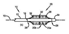
図1は、本発明の一実施形態によるカテーテルの千鳥配置された焼灼素子のアセンブリを示す。図1aの斜視図では、焼灼カテーテル10は、近位端(図示せず)と遠位端14との間で長手方向軸16に沿って長手方向に延びる細長いカテーテル本体12を備える。焼灼素子アセンブリ20は、カテーテル本体12に接続された複数の焼灼素子22を備える。焼灼素子22は、長手方向および/または横方向に互いに不連続に離間しており、焼灼素子22の少なくとも2つが長手方向に互いに離間している。 FIG. 1 shows an assembly of staggered ablation elements of a catheter according to one embodiment of the present invention. In the perspective view of FIG. 1 a, the
この実施形態では、焼灼素子22はRF電極などの電極である。焼灼電極アセンブリ20はカテーテル本体12の遠位端14に接続されている。図1a〜1dに示すように、電極アセンブリ20は、ほぼ長手方向に向けられてよい複数の背骨24を備える。各背骨24は、カテーテル本体12に接続された近位端26と、遠位端28と、を有する。背骨24の遠位端28は背骨遠位接合部30に接続されている。各背骨24は、中間セグメント32、背骨24の近位端26と中間セグメント32との間の近位剛性変化部、および背骨24の遠位端28と中間セグメント32との間の遠位剛性変化部を備える。背骨24は中間セグメント32に複数の焼灼電極22を備える。 In this embodiment, the
図1bに示すように、電極アセンブリ20は、折畳配置20aと拡張配置20bとの間で移動可能であり、拡張配置20bにおける背骨24の中間セグメント32は、折畳配置20aに関する背骨24の近位端26および遠位端28に対して外側に移動する。 As shown in FIG. 1b, the
各背骨24は、背骨24の中間セグメント32と近位端26との間に連結された近位脚部34、および背骨24の中間セグメント32と遠位端28との間に連結された遠位脚部36を備える。各背骨24は、近位脚部34と中間セグメント32との間に連結された近位蝶番44、および遠位脚部36と中間セグメント32との間に連結された遠位蝶番46を備える。蝶番44、46は、この実施形態では、折畳配置20aと拡張配置20bとの間での背骨24の中間セグメント32の移動を容易にする剛性変化部である。さらに、各背骨24は、折畳配置20aと拡張配置20bとの間での背骨24の中間セグメント32の移動をさらに容易にするため、近位脚部34と近位端26との間に連結された近位端蝶番40、および遠位脚部36と遠位端28との間に連結された遠位端蝶番42をさらに備えてもよい。 Each
使用時、電極アセンブリ20を有するカテーテル10は、折畳配置20aで(ガイドシース等に入れられて)血管等に挿入され、拡張配置20bに展開される。血管内で電極アセンブリ20を横切る血流を可能にし、閉塞を低減または回避するため、図1cの背骨24は、幅の狭い中間セグメント32、近位脚部34、および遠位脚部36を有する。図1dでは、中間セグメント32は比較的幅が広いが、近位脚部34および遠位脚部36は、中間セグメント32より断面積が小さくなるようにテーパ状になっており、それによって閉塞が低減する。さらに、電極アセンブリ20は、血管内での移動がより容易に且つより円滑になるように、好ましくは鋭い隅部も縁部も有しておらず、丸みのある隅部および縁部を有する。 In use, the
拡張配置20bの焼灼電極22は、被焼灼面に接触して、組織の焼灼、例えば神経の除神経を行う。焼灼電極22の表面接触を確実にするため、中間セグメント32は、好ましくは、拡張配置20bでの屈曲を回避するまたは最小限にするのに十分な剛性を有する。電極アセンブリ20は、任意の適した機構により折畳配置20aから拡張配置20bに移動する。一実施例では、背骨24の近位脚部34、遠位脚部36、近位端蝶番40および遠位端蝶番42のいずれかまたは全部が弾性付勢され(例えば、ばねまたは記憶材料で)、電極アセンブリ20を拡張配置20bに向かって移動させてもよい。別の実施例では、電極アセンブリ20の中心にある長手方向ロッド60が、背骨遠位接合部30に接続されており、背骨遠位接合部30をカテーテル本体12の遠位端14の方に引いて電極アセンブリ20を拡張配置20bに向かって移動させるために使用されることができる。
The
焼灼電極の温度を測定するために複数の温度センサ50が複数の焼灼素子22と熱的に結合されている。図2は、背骨24上に支持されている電極22に隣接して配置された温度センサ50の一実施例を示す、背骨24の断面図である。さらに、背骨24は、図2に示すように、灌流液を焼灼電極22の方に送出するため、複数の焼灼電極22の近傍に複数の灌流液流路54を備えてもよい。 A plurality of
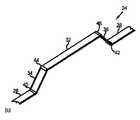
図3は、本発明の別の実施形態によるカテーテルの千鳥配置された焼灼素子のアセンブリを示す。図3aは折畳配置の電極アセンブリ60を示し、図3bは拡張配置の電極アセンブリ60を示す。電極アセンブリ60は、カテーテル本体の遠位端に接続されていてもよく、またはカテーテル本体の遠位端から近位方向に配置されていてもよい。 FIG. 3 shows an assembly of staggered ablation elements of a catheter according to another embodiment of the present invention. 3a shows the
図3の電極アセンブリ60は、図1の電極アセンブリ20と幾つかの点で異なる。まず、焼灼電極62はそれぞれ、横方向の寸法よりその長手方向により大きな寸法を有する。電極62の横方向の寸法は、電極62を支持する背骨64の横方向の寸法より大きい。各背骨64は、近位脚部66、遠位脚部68、および中間セグメント70を有する。各電極62は円弧状の形状を有し、これにより長手方向軸に対して横方向を向いている焼灼ゾーンが形成される。このような焼灼ゾーンは、ほぼ長手方向を向いている腎神経の除神経を行うのに、より効率的且つ有効である。 The
図1の電極アセンブリ20とは異なり、図3の電極アセンブリ60は、背骨に蝶番を備えていない。代わりに、背骨64は、電極アセンブリ60の折畳配置から拡張配置への移動を容易にするように構成されている。例えば、近位脚部66は中間セグメント70より剛性が低く、遠位脚部68は中間セグメント70より剛性が低い。そのため、近位脚部66および遠位脚部68は、電極アセンブリ60を拡張配置に移動させる力がかかると屈曲または変形することになる。その力は、形状記憶材料(例えば、ニチノール)製の背骨64の少なくとも1つによって生じ得る。電極アセンブリ60の中心にある長手方向ロッド65は、背骨遠位接合部67に接続されていてもよく、背骨遠位接合部67を近位方向に引いて電極アセンブリ60を拡張配置20bに向かって移動させるために使用されることができる。 Unlike the
図4は、本発明の別の実施形態によるカテーテルの千鳥配置された焼灼素子のアセンブリを示す。図4aは折畳配置の電極アセンブリ80を示し、図4bは拡張配置の電極アセンブリ80を示す。図4の電極アセンブリ80は、図3の電極アセンブリ60と1つの点で異なる。血管内での電極アセンブリの移動がより容易に且つより円滑になるように、鋭い隅部の代わりにテーパ状の/丸みのある隅部81を使用する。電極アセンブリ80の中心にある長手方向のロッド85は、背骨遠位接合部87に接続されていてもよく、背骨遠位接合部87を遠位方向に引いて電極アセンブリ80を拡張配置に向かって移動させるために使用されることができる。 FIG. 4 shows an assembly of staggered ablation elements of a catheter according to another embodiment of the present invention. 4a shows the
図5の電極アセンブリ60は図3の電極アセンブリ60に類似している。それらは、焼灼電極62の配置だけが異なっている。図3では、焼灼電極62は長手方向に螺旋状に千鳥配置されている。図5では、焼灼電極62はほぼ対向する対になるように配置されている。これらの実施例は、焼灼電極62を千鳥状に配置して電極アセンブリ60を形成する多くの異なる方法の幾つかを示す。 The
図6の電極アセンブリ80は図4の電極アセンブリ80に類似している。それらは、焼灼電極82の配置だけが異なっている。図4では、焼灼電極82は長手方向に螺旋状に千鳥配置されている。図6では、焼灼電極82はほぼ対向する対になるように配置されている。これらの実施例は、焼灼電極82を千鳥状に配置して電極アセンブリ80を形成する多くの異なる方法の幾つかを示す。 The
図7は、本発明の別の実施形態によるカテーテルの千鳥配置された焼灼素子のアセンブリを示す。遠位端92を有するカテーテル本体90を示す。図7aは折畳配置の電極アセンブリ100を示し、図7bは拡張配置の電極アセンブリ100を示す。複数の焼灼電極102が、遠位端92に対して近位方向にあるカテーテル本体90の外周面に接続されている。焼灼電極102は、図7aの折畳配置のカテーテル本体90の外周面に当接して配置されている。複数の弾性付勢部材104が、焼灼電極102を図7bの拡張配置の方に付勢する。図示する実施形態では、各焼灼電極102は、1つの焼灼電極102をカテーテル本体90から離れるように外側に付勢する、対応する弾性付勢部材104を有する。焼灼電極102は、それぞれ横方向の寸法の方がその長手方向の寸法より大きい円弧状である。 FIG. 7 shows an assembly of staggered ablation elements of a catheter according to another embodiment of the present invention. A
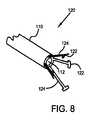
図8は、本発明の別の実施形態によるカテーテルの千鳥配置された焼灼素子のアセンブリを示す。遠位端112を有するカテーテル本体110を示す。電極アセンブリ120は、カテーテル本体90の遠位端92に接続されている複数の焼灼電極122を備える。複数の弾性付勢部材124が、図8に示すように、焼灼電極122を拡張配置の方に外側に付勢する。 FIG. 8 shows an assembly of staggered ablation elements of a catheter according to another embodiment of the present invention. A
図9は、カテーテルの長手方向軸周りの開いた弧状セグメントにわたる焼灼素子の焼灼ゾーン130を示す。各焼灼素子は、対応する焼灼ゾーン(130a、130b、130c、...)を有する。各焼灼素子に関して、焼灼ゾーンは、焼灼ゾーン内で組織の焼灼、例えば神経の除神経を行うために十分なエネルギーで通電される領域である。焼灼ゾーン130は、対応する焼灼素子とほぼ同じ形状およびサイズであってもよい。RF電極等に関して、焼灼ゾーンは、対応するRF電極より大きくなる可能性がある。焼灼素子の焼灼ゾーン130が、長手方向軸周りの1以上の開いた弧状セグメントにわたるように、焼灼素子は千鳥状に配置されている。
FIG. 9 shows the ablation zone 130 of the ablation element over an open arcuate segment about the longitudinal axis of the catheter. Each ablation element has a corresponding ablation zone (130a, 130b, 130c, ...). For each ablation element, the ablation zone is an area that is energized with sufficient energy to perform tissue ablation, eg, nerve denervation, within the ablation zone. The ablation zone 130 may be substantially the same shape and size as the corresponding ablation element. For RF electrodes and the like, the ablation zone can be larger than the corresponding RF electrode. The ablation elements are staggered so that the ablation zone 130 of the ablation element spans one or more open arc segments about the longitudinal axis.
図10は、長手方向軸に垂直な任意の横方向の面上に長手方向に突出したとき、カテーテルの長手方向軸周りの閉じたループにわたる、焼灼素子全部の焼灼ゾーン130を示す。図10に示される実施形態では、閉じたループは完全に閉じている。他の実施形態では、ループは実質的に閉じている。実質的に閉じたループは、1つ以上の開放部分を有する。実質的に閉じたループの開放部分の総計は、実質的に閉じたループの約30%以下である。エネルギー源は、独立して制御される焼灼素子に同時にまたは順次または任意の順番でエネルギーを供給し、焼灼ゾーンを形成する。このようにして、組織焼灼、例えば腎除神経等を効率的に、有効に、且つ迅速に、使用者の選択に従って行うことができる。FIG. 10 shows the ablation zone 130 of the entire ablation element over a closed loop about the longitudinal axis of the catheter when projected longitudinally on any lateral surface perpendicular to the longitudinal axis. In the embodiment shown in FIG. 10, the closed loop is completely closed. In other embodiments, the loop is substantially closed. A substantially closed loop has one or more open portions. The sum of the open portions of the substantially closed loop is no more than about 30% of the substantially closed loop. The energy source supplies energy to the independently controlled ablation elements simultaneously or sequentially or in any order to form an ablation zone. In this way, tissue ablation, such as renal denervation, can be performed efficiently, effectively and quickly according to the user's choice.
特定の実施形態では、拡張配置の焼灼電極は、長手方向軸周りの1以上の開いた弧状セグメントにわたるが、長手方向軸に垂直な任意の横方向の面上に長手方向に突出する拡張配置の焼灼電極全部では、長手方向軸の周囲の実質的に閉じたループにわたる。実質的に閉じたループは1以上の開放部分を有する。実質的に閉じたループの開放部分の総計は、実質的に閉じたループの約30%以下である。 In certain embodiments, the expanded arrangement of ablation electrodes spans one or more open arcuate segments about the longitudinal axis but extends in an extended arrangement that protrudes longitudinally on any lateral plane perpendicular to the longitudinal axis. All ablation electrodes span a substantially closed loop around the longitudinal axis. A substantially closed loop has one or more open portions. The sum of the open portions of the substantially closed loop is no more than about 30% of the substantially closed loop.
図11は、カテーテル182の内腔にガイドワイヤ200を挿通することにより、カテーテルの千鳥配置された焼灼素子のアセンブリ180を手術部位に導入するためのオーバーザワイヤ構成を示す。ガイドワイヤ200は、アセンブリ180の遠位端にある開口部202を通り、アセンブリ180を通ってカテーテル182の内腔まで延びる管204をその遠位端から近位端まで通って延びる。アセンブリ180の遠位端は、カテーテル182の遠位端184の遠位方向に配置されている。 FIG. 11 illustrates an over-the-wire configuration for introducing a staggered catheter
図12は、アセンブリ190の遠位端に設けられた遠位開口部212にガイドワイヤ210を挿通することにより、カテーテルの千鳥配置された焼灼素子のアセンブリ190を手術部位に導入するためのオーバーザワイヤ構成を示す。ガイドワイヤ210は、アセンブリ190の遠位端にある遠位開口部212を通り、および切り欠きまたは側部もしくは中間開口部216を有する管214を一部通って延び、その切り欠きまたは側部/中間開口部から出て、さらにカテーテル192の外部をカテーテル192の近位端の方に延びる。図12では、遠位開口部212と中間開口部216は両方とも、カテーテル192の遠位端194の遠位方向に配置されている。 FIG. 12 shows an over-the-wire for introducing a staggered catheter
説明中、本発明が十分理解されるように説明するため、多くの詳細を記載している。しかし、これらの具体的詳細が全て本発明の実施に必要なわけではないことが当業者には明らかであろう。さらに、本明細書に特定の実施形態を図示し説明してきたが、同じ目的を達成するように計算されている構成であればいずれも、開示する特定の実施形態の代わりに使用できることが当業者には分かる。本開示は、本発明の変更形態または変形形態のいずれも全て包含するものとし、以下の特許請求の範囲で使用される用語は、本発明を本明細書中に開示される特定の実施形態に限定するものと解釈すべきではない。むしろ、本発明の範囲はもっぱら、確立されたクレームの解釈の基本原則に従って解釈されるべきである以下のクレーム、ならびにこのようなクレームの権利範囲に含まれる均等物の範囲全体によって決定されるものとする。 In the description, numerous details are set forth to provide a thorough understanding of the present invention. However, it will be apparent to one skilled in the art that these specific details may not all be necessary for the practice of the invention. Further, although specific embodiments have been illustrated and described herein, those skilled in the art will appreciate that any configuration calculated to achieve the same purpose can be used in place of the disclosed specific embodiments. I understand. This disclosure is intended to encompass any and all modifications or variations of the present invention, and the terms used in the following claims shall refer to the specific embodiments disclosed herein. It should not be construed as limiting. Rather, the scope of the present invention is determined solely by the following claims, which should be construed in accordance with the basic principles of interpretation of established claims, as well as the full scope of equivalents included in the scope of such claims. And
Claims (26)
Translated fromJapanese前記カテーテル本体に接続された複数の焼灼素子を有する焼灼素子アセンブリであって、各焼灼素子が、焼灼ゾーン内で組織の焼灼を行うために十分なエネルギーで通電されて焼灼ゾーンを形成し、折畳配置と拡張配置との間で移動可能である焼灼素子アセンブリと、を備える焼灼カテーテルであって、
前記焼灼素子は前記長手方向に螺旋状に千鳥状に配置され、前記焼灼素子の焼灼ゾーンは前記長手方向軸周りの複数の弧状セグメントにわたるが、前記長手方向軸に垂直な面上に長手方向に投影された焼灼素子全部の焼灼ゾーンは、前記拡張配置において前記長手方向軸周りの閉じたループにわたる、焼灼カテーテル。An elongate catheter body extending longitudinally along a longitudinal axis between a proximal end and a distal end;
Wherein a cautery device assembly having a plurality of ablation elements connected to the catheter body, each ablation element to form an ablation zone is energized with sufficient energy to performthe tempering灼 tissue in the ablation zone, A cautery element assembly that is movable between a collapsed configuration and an expanded configuration, comprising:
The ablation elements are arranged in a staggeredspiral in the longitudinal direction, and the ablation zone of the ablation element spans a plurality of arcuate segments around the longitudinal axis, but in a longitudinal direction ona plane perpendicular to the longitudinal axis. The ablation catheter of the entire projected ablation element spans a closed loop around the longitudinal axisin the expanded configuration .
前記焼灼素子アセンブリが、前記カテーテル本体の内腔を通って延びる前記ガイドワイヤを受け入れる開口部を有する遠位端を備え、前記焼灼素子アセンブリの遠位端が前記カテーテル本体の遠位端の遠位方向に配置されている、請求項1に記載の焼灼カテーテル。Beforehear catheters body has a lumen from the proximal end to the distal end of the prehear catheters body to accept a guide wire,
The ablation element assembly, prior tohear catheters with a distal end having an opening for receiving the guide wire extending through the lumen of the body, distal of the distal end beforehear catheters body of the ablation device assembly The ablation catheter of claim 1, wherein the ablation catheter is disposed distally of the end.
前記カテーテル本体から離れるように外側に焼灼電極を付勢する弾性付勢部材によって前記カテーテル本体に接続された複数の焼灼電極を有する電極アセンブリであって、各焼灼電極が、焼灼ゾーン内で組織の焼灼を行うために十分なエネルギーで通電されて焼灼ゾーンを形成する、電極アセンブリと、を備える焼灼カテーテルであって、
前記電極アセンブリが折畳配置と拡張配置との間で移動可能であり、前記弾性付勢部材が前記カテーテル本体から離れて前記拡張配置に向かって外側に前記焼灼電極を付勢し、
前記焼灼電極は前記長手方向に螺旋状に千鳥状に配置され、前記焼灼電極の焼灼ゾーンは前記長手方向軸周りの複数の弧状セグメントにわたり、前記長手方向軸に垂直な面上に長手方向に投影された前記焼灼電極全部の焼灼ゾーンが、前記拡張配置において前記長手方向軸周りの閉じたループにわたる、焼灼カテーテル。An elongate catheter body extending longitudinally along a longitudinal axis between a proximal end and a distal end;
An electrode assembly having a plurality of ablation electrodes connected to the catheter body by an elastic biasing member that urges the ablation electrodes outwardly away from the catheter body, wherein each ablation electrode includes tissue ablation within the ablation zone. to form an ablation zone is energized with sufficient energy to performthe tempering灼, a cautery catheter comprising an electrode assembly, a,
The electrode assembly is movable between a folded configuration and an expanded configuration, and the resilient biasing member biases the ablation electrode outward from the catheter body toward the expanded configuration;
The ablation electrodes arespirally arranged in the longitudinal direction, and the ablation zone of the ablation electrode extends over a plurality of arc segments around the longitudinal axis and projects in a longitudinal direction ona plane perpendicularto the longitudinal axis. An ablation catheter in which the entire ablation zone of the ablated electrode spans a closed loop about the longitudinal axisin the expanded configuration .
前記拡張配置の焼灼電極が、前記長手方向軸周りの複数の弧状セグメントにわたり、前記長手方向軸に垂直な面上に長手方向に投影された前記拡張配置の焼灼電極全部が、前記拡張配置において前記長手方向軸の周囲の閉じたループにわたる、請求項8に記載の焼灼カテーテル。The expanded arrangement of the ablation electrode is in contact with the ablation surface;
The expanded arrangement of ablation electrodes spans a plurality of arcuate segments about the longitudinal axis and is projected longitudinally ontoa plane perpendicularto the longitudinal axis so that all of the expanded arrangement of ablation electrodes are in theexpanded arrangement 9. An ablation catheter according to claim 8, which spans a closed loop around the longitudinal axis.
前記カテーテル本体に接続された電極アセンブリであって、電極アセンブリが複数の背骨を有し、前記背骨のそれぞれが、前記カテーテル本体に接続された近位端と遠位端とを有し、前記背骨の遠位端が背骨遠位接合部に接続されており、各背骨が、中間セグメント、前記背骨の近位端と中間セグメントとの間の近位剛性変化部と、前記背骨の遠位端と中間セグメントとの間の遠位剛性変化部と、を備え、前記背骨が前記中間セグメントに複数の焼灼電極を備え、各焼灼電極が、焼灼ゾーン内で組織の焼灼を行うために十分なエネルギーで通電されて焼灼ゾーンを形成する、電極アセンブリと、を備える焼灼カテーテルであって、
前記電極アセンブリが折畳配置と拡張配置との間で移動可能であり、前記拡張配置の前記背骨の中間セグメントが、前記折畳配置に関する前記背骨の近位端と遠位端とに対して外側に移動し、
前記焼灼電極が前記中間セグメント上に前記長手方向に螺旋状に千鳥状に配置され、前記焼灼電極の焼灼ゾーンが前記長手方向軸周りの複数の弧状セグメントにわたり、前記長手方向軸に垂直な面上に長手方向に投影された前記焼灼電極全部の焼灼ゾーンが、前記拡張配置において前記長手方向軸周りの閉じたループにわたる、焼灼カテーテル。An elongate catheter body extending longitudinally along a longitudinal axis between a proximal end and a distal end;
An electrode assembly connected to the catheter body, the electrode assembly having a plurality of spines, each of the spines having a proximal end and a distal end connected to the catheter body, the spine A distal end of the spine, each spine having an intermediate segment, a proximal stiffness change between the proximal and intermediate segments of the spine, and a distal end of the spine. includes a distal rigidity changing portion between the middle segment, wherein the spine comprises a plurality of ablation electrodes to the intermediate segment, each ablation electrode is sufficient energy in order to performthe tempering灼 tissue in the ablation zone An ablation catheter comprising an electrode assembly energized at to form an ablation zone,
The electrode assembly is movable between a folded configuration and an expanded configuration, and an intermediate segment of the spine in the expanded configuration is external to the proximal and distal ends of the spine with respect to the folded configuration Go to
The ablation electrode isspirally arranged in the longitudinal direction on the intermediate segment, and the ablation zone of the ablation electrode extends over a plurality of arcuate segments around the longitudinal axis, ona plane perpendicularto the longitudinal axis. An ablation catheter in which the ablation zone of all of the ablation electrodes projected longitudinally across the channel spans a closed loop about the longitudinal axisin the expanded configuration .
前記拡張配置の焼灼電極が前記長手方向軸周りの複数の弧状セグメントにわたり、前記長手方向軸に垂直な面上に長手方向に投影された前記拡張配置の焼灼電極全部が、前記拡張配置において前記長手方向軸周りの閉じたループにわたる、請求項17に記載の焼灼カテーテル。The expanded arrangement of the ablation electrode is in contact with the ablation surface;
The expanded arrangement of ablation electrodes spans a plurality of arcuate segments about the longitudinal axis and is projected longitudinally ontoa plane perpendicularto the longitudinal axis so that all of the expanded arrangement of ablation electrodes are in theextended arrangement in the longitudinal direction. The ablation catheter of claim 17, which spans a closed loop about the directional axis.
18. An ablation catheter according to claim 17, wherein at least one of the spines has a shape memory material that biases the spine toward the expanded configuration.
Applications Claiming Priority (3)
| Application Number | Priority Date | Filing Date | Title |
|---|---|---|---|
| US26097809P | 2009-11-13 | 2009-11-13 | |
| US61/260,978 | 2009-11-13 | ||
| PCT/US2010/056644WO2011060339A1 (en) | 2009-11-13 | 2010-11-15 | Assembly of staggered ablation elements |
Publications (2)
| Publication Number | Publication Date |
|---|---|
| JP2013510689A JP2013510689A (en) | 2013-03-28 |
| JP6013186B2true JP6013186B2 (en) | 2016-10-25 |
Family
ID=43428595
Family Applications (1)
| Application Number | Title | Priority Date | Filing Date |
|---|---|---|---|
| JP2012539047AExpired - Fee RelatedJP6013186B2 (en) | 2009-11-13 | 2010-11-15 | Staggered arrangement of shochu elements |
Country Status (8)
| Country | Link |
|---|---|
| US (1) | US8979839B2 (en) |
| EP (1) | EP2498706B1 (en) |
| JP (1) | JP6013186B2 (en) |
| AU (1) | AU2010319333B2 (en) |
| BR (1) | BR112012011042A2 (en) |
| CA (1) | CA2781951A1 (en) |
| CR (1) | CR20120291A (en) |
| WO (1) | WO2011060339A1 (en) |
Families Citing this family (254)
| Publication number | Priority date | Publication date | Assignee | Title |
|---|---|---|---|---|
| US8974446B2 (en)* | 2001-10-11 | 2015-03-10 | St. Jude Medical, Inc. | Ultrasound ablation apparatus with discrete staggered ablation zones |
| US8347891B2 (en)* | 2002-04-08 | 2013-01-08 | Medtronic Ardian Luxembourg S.A.R.L. | Methods and apparatus for performing a non-continuous circumferential treatment of a body lumen |
| US8150519B2 (en) | 2002-04-08 | 2012-04-03 | Ardian, Inc. | Methods and apparatus for bilateral renal neuromodulation |
| DE202004021953U1 (en)* | 2003-09-12 | 2013-06-19 | Vessix Vascular, Inc. | Selectable eccentric remodeling and / or ablation of atherosclerotic material |
| US9713730B2 (en) | 2004-09-10 | 2017-07-25 | Boston Scientific Scimed, Inc. | Apparatus and method for treatment of in-stent restenosis |
| US8396548B2 (en) | 2008-11-14 | 2013-03-12 | Vessix Vascular, Inc. | Selective drug delivery in a lumen |
| JP5219518B2 (en) | 2004-12-09 | 2013-06-26 | ザ ファウンドリー, エルエルシー | Aortic valve repair |
| EP2438877B1 (en) | 2005-03-28 | 2016-02-17 | Vessix Vascular, Inc. | Intraluminal electrical tissue characterization and tuned RF energy for selective treatment of atheroma and other target tissues |
| US8019435B2 (en) | 2006-05-02 | 2011-09-13 | Boston Scientific Scimed, Inc. | Control of arterial smooth muscle tone |
| WO2008014629A2 (en) | 2006-08-03 | 2008-02-07 | Christoph Scharf | Method and device for determining and presenting surface charge and dipole densities on cardiac walls |
| EP2076198A4 (en) | 2006-10-18 | 2009-12-09 | Minnow Medical Inc | Inducing desirable temperature effects on body tissue |
| JP5559539B2 (en) | 2006-10-18 | 2014-07-23 | べシックス・バスキュラー・インコーポレイテッド | System that induces desirable temperature effects on body tissue |
| EP2455036B1 (en) | 2006-10-18 | 2015-07-15 | Vessix Vascular, Inc. | Tuned RF energy and electrical tissue characterization for selective treatment of target tissues |
| WO2008070189A2 (en) | 2006-12-06 | 2008-06-12 | The Cleveland Clinic Foundation | Method and system for treating acute heart failure by neuromodulation |
| US8496653B2 (en) | 2007-04-23 | 2013-07-30 | Boston Scientific Scimed, Inc. | Thrombus removal |
| EP2737849A3 (en) | 2008-01-17 | 2014-10-29 | Christoph Scharf | A device and method for the geometric determination of electrical dipole densities on the cardiac wall |
| EP2355737B1 (en) | 2008-11-17 | 2021-08-11 | Boston Scientific Scimed, Inc. | Selective accumulation of energy without knowledge of tissue topography |
| US8551096B2 (en) | 2009-05-13 | 2013-10-08 | Boston Scientific Scimed, Inc. | Directional delivery of energy and bioactives |
| US9226791B2 (en) | 2012-03-12 | 2016-01-05 | Advanced Cardiac Therapeutics, Inc. | Systems for temperature-controlled ablation using radiometric feedback |
| US9277961B2 (en) | 2009-06-12 | 2016-03-08 | Advanced Cardiac Therapeutics, Inc. | Systems and methods of radiometrically determining a hot-spot temperature of tissue being treated |
| US8954161B2 (en) | 2012-06-01 | 2015-02-10 | Advanced Cardiac Therapeutics, Inc. | Systems and methods for radiometrically measuring temperature and detecting tissue contact prior to and during tissue ablation |
| US8926605B2 (en) | 2012-02-07 | 2015-01-06 | Advanced Cardiac Therapeutics, Inc. | Systems and methods for radiometrically measuring temperature during tissue ablation |
| JP6013186B2 (en) | 2009-11-13 | 2016-10-25 | セント ジュード メディカル インコーポレイテッド | Staggered arrangement of shochu elements |
| WO2011126580A2 (en) | 2010-04-09 | 2011-10-13 | Minnow Medical, Inc. | Power generating and control apparatus for the treatment of tissue |
| US9192790B2 (en) | 2010-04-14 | 2015-11-24 | Boston Scientific Scimed, Inc. | Focused ultrasonic renal denervation |
| US8473067B2 (en) | 2010-06-11 | 2013-06-25 | Boston Scientific Scimed, Inc. | Renal denervation and stimulation employing wireless vascular energy transfer arrangement |
| US9084609B2 (en) | 2010-07-30 | 2015-07-21 | Boston Scientific Scime, Inc. | Spiral balloon catheter for renal nerve ablation |
| US9155589B2 (en) | 2010-07-30 | 2015-10-13 | Boston Scientific Scimed, Inc. | Sequential activation RF electrode set for renal nerve ablation |
| US9463062B2 (en) | 2010-07-30 | 2016-10-11 | Boston Scientific Scimed, Inc. | Cooled conductive balloon RF catheter for renal nerve ablation |
| US9408661B2 (en) | 2010-07-30 | 2016-08-09 | Patrick A. Haverkost | RF electrodes on multiple flexible wires for renal nerve ablation |
| US9358365B2 (en) | 2010-07-30 | 2016-06-07 | Boston Scientific Scimed, Inc. | Precision electrode movement control for renal nerve ablation |
| US8974451B2 (en) | 2010-10-25 | 2015-03-10 | Boston Scientific Scimed, Inc. | Renal nerve ablation using conductive fluid jet and RF energy |
| US9220558B2 (en) | 2010-10-27 | 2015-12-29 | Boston Scientific Scimed, Inc. | RF renal denervation catheter with multiple independent electrodes |
| US9028485B2 (en) | 2010-11-15 | 2015-05-12 | Boston Scientific Scimed, Inc. | Self-expanding cooling electrode for renal nerve ablation |
| US9089350B2 (en) | 2010-11-16 | 2015-07-28 | Boston Scientific Scimed, Inc. | Renal denervation catheter with RF electrode and integral contrast dye injection arrangement |
| US9668811B2 (en) | 2010-11-16 | 2017-06-06 | Boston Scientific Scimed, Inc. | Minimally invasive access for renal nerve ablation |
| EP4032486A1 (en) | 2010-11-16 | 2022-07-27 | TVA Medical, Inc. | Devices for forming a fistula |
| US9326751B2 (en) | 2010-11-17 | 2016-05-03 | Boston Scientific Scimed, Inc. | Catheter guidance of external energy for renal denervation |
| US9060761B2 (en) | 2010-11-18 | 2015-06-23 | Boston Scientific Scime, Inc. | Catheter-focused magnetic field induced renal nerve ablation |
| US9023034B2 (en) | 2010-11-22 | 2015-05-05 | Boston Scientific Scimed, Inc. | Renal ablation electrode with force-activatable conduction apparatus |
| US9192435B2 (en) | 2010-11-22 | 2015-11-24 | Boston Scientific Scimed, Inc. | Renal denervation catheter with cooled RF electrode |
| US20120157993A1 (en) | 2010-12-15 | 2012-06-21 | Jenson Mark L | Bipolar Off-Wall Electrode Device for Renal Nerve Ablation |
| US9220561B2 (en) | 2011-01-19 | 2015-12-29 | Boston Scientific Scimed, Inc. | Guide-compatible large-electrode catheter for renal nerve ablation with reduced arterial injury |
| US9757044B2 (en) | 2011-03-10 | 2017-09-12 | Acutus Medical, Inc. | Device and method for the geometric determination of electrical dipole densities on the cardiac wall |
| US8909316B2 (en) | 2011-05-18 | 2014-12-09 | St. Jude Medical, Cardiology Division, Inc. | Apparatus and method of assessing transvascular denervation |
| US20140107639A1 (en)* | 2011-06-06 | 2014-04-17 | St. Jude Medical Cardiology Division, Inc. | Renal denervation system and method |
| US11033318B2 (en) | 2011-06-14 | 2021-06-15 | Aerin Medical, Inc. | Methods and devices to treat nasal airways |
| US9237924B2 (en) | 2011-06-14 | 2016-01-19 | Aerin Medical, Inc. | Methods and devices to treat nasal airways |
| US20240050143A1 (en) | 2011-06-14 | 2024-02-15 | Aerin Medical Inc. | Methods and devices to treat nasal airways |
| US11304746B2 (en)* | 2011-06-14 | 2022-04-19 | Aerin Medical Inc. | Method of treating airway tissue to reduce mucus secretion |
| US9415194B2 (en) | 2011-06-14 | 2016-08-16 | Aerin Medical Inc. | Post nasal drip treatment |
| US10456185B2 (en) | 2011-06-14 | 2019-10-29 | Aerin Medical, Inc. | Methods and devices to treat nasal airways |
| US11241271B2 (en) | 2011-06-14 | 2022-02-08 | Aerin Medical Inc. | Methods of treating nasal airways |
| US10722282B2 (en) | 2011-06-14 | 2020-07-28 | Aerin Medical, Inc. | Methods and devices to treat nasal airways |
| WO2013009977A1 (en)* | 2011-07-12 | 2013-01-17 | David Lambert | Device for reducing renal sympathetic nerve activity |
| CN103813745B (en) | 2011-07-20 | 2016-06-29 | 波士顿科学西美德公司 | In order to visualize, be directed at and to melt transcutaneous device and the method for nerve |
| EP2734264B1 (en) | 2011-07-22 | 2018-11-21 | Boston Scientific Scimed, Inc. | Nerve modulation system with a nerve modulation element positionable in a helical guide |
| JP6318088B2 (en) | 2011-07-26 | 2018-04-25 | アンフォラ メディカル, インコーポレイテッド | Apparatus and method for modulating pelvic nerve tissue |
| US9427579B2 (en) | 2011-09-29 | 2016-08-30 | Pacesetter, Inc. | System and method for performing renal denervation verification |
| WO2013055826A1 (en)* | 2011-10-10 | 2013-04-18 | Boston Scientific Scimed, Inc. | Medical devices including ablation electrodes |
| US9420955B2 (en) | 2011-10-11 | 2016-08-23 | Boston Scientific Scimed, Inc. | Intravascular temperature monitoring system and method |
| EP2765940B1 (en) | 2011-10-11 | 2015-08-26 | Boston Scientific Scimed, Inc. | Off-wall electrode device for nerve modulation |
| US9364284B2 (en) | 2011-10-12 | 2016-06-14 | Boston Scientific Scimed, Inc. | Method of making an off-wall spacer cage |
| EP2768568B1 (en) | 2011-10-18 | 2020-05-06 | Boston Scientific Scimed, Inc. | Integrated crossing balloon catheter |
| US9162046B2 (en) | 2011-10-18 | 2015-10-20 | Boston Scientific Scimed, Inc. | Deflectable medical devices |
| CN102462532B (en)* | 2011-10-25 | 2013-03-13 | 张石江 | Conduit system with label testing and ablation functions in blood vessels |
| US8951251B2 (en) | 2011-11-08 | 2015-02-10 | Boston Scientific Scimed, Inc. | Ostial renal nerve ablation |
| WO2013074813A1 (en) | 2011-11-15 | 2013-05-23 | Boston Scientific Scimed, Inc. | Device and methods for renal nerve modulation monitoring |
| US10470756B2 (en) | 2011-11-16 | 2019-11-12 | VentureMD Innovations, LLC | Suture anchor and method |
| US10136883B2 (en) | 2011-11-16 | 2018-11-27 | VentureMD Innovations, LLC | Method of anchoring a suture |
| US9119632B2 (en) | 2011-11-21 | 2015-09-01 | Boston Scientific Scimed, Inc. | Deflectable renal nerve ablation catheter |
| JP6441679B2 (en) | 2011-12-09 | 2018-12-19 | メタベンション インコーポレイテッド | Therapeutic neuromodulation of the liver system |
| US9265969B2 (en) | 2011-12-21 | 2016-02-23 | Cardiac Pacemakers, Inc. | Methods for modulating cell function |
| US9028472B2 (en) | 2011-12-23 | 2015-05-12 | Vessix Vascular, Inc. | Methods and apparatuses for remodeling tissue of or adjacent to a body passage |
| EP2797534A1 (en) | 2011-12-28 | 2014-11-05 | Boston Scientific Scimed, Inc. | Device and methods for nerve modulation using a novel ablation catheter with polymeric ablative elements |
| US9050106B2 (en) | 2011-12-29 | 2015-06-09 | Boston Scientific Scimed, Inc. | Off-wall electrode device and methods for nerve modulation |
| US8934988B2 (en) | 2012-03-16 | 2015-01-13 | St. Jude Medical Ab | Ablation stent with meander structure |
| US9113929B2 (en) | 2012-04-19 | 2015-08-25 | St. Jude Medical, Cardiology Division, Inc. | Non-electric field renal denervation electrode |
| US10660703B2 (en) | 2012-05-08 | 2020-05-26 | Boston Scientific Scimed, Inc. | Renal nerve modulation devices |
| US9439722B2 (en) | 2012-05-09 | 2016-09-13 | Biosense Webster (Israel) Ltd. | Ablation targeting nerves in or near the inferior vena cava and/or abdominal aorta for treatment of hypertension |
| US9592086B2 (en) | 2012-07-24 | 2017-03-14 | Boston Scientific Scimed, Inc. | Electrodes for tissue treatment |
| US10321946B2 (en) | 2012-08-24 | 2019-06-18 | Boston Scientific Scimed, Inc. | Renal nerve modulation devices with weeping RF ablation balloons |
| WO2014056460A1 (en)* | 2012-08-29 | 2014-04-17 | 第三军医大学第一附属医院 | Multifunctional ablation catheter system for renal sympathetic denervation |
| EP2890292B1 (en) | 2012-08-31 | 2021-01-13 | Acutus Medical, Inc. | Catheter system for the heart |
| US8612022B1 (en) | 2012-09-13 | 2013-12-17 | Invatec S.P.A. | Neuromodulation catheters and associated systems and methods |
| CN104780859B (en) | 2012-09-17 | 2017-07-25 | 波士顿科学西美德公司 | Self-positioning electrode systems and methods for renal neuromodulation |
| US10398464B2 (en) | 2012-09-21 | 2019-09-03 | Boston Scientific Scimed, Inc. | System for nerve modulation and innocuous thermal gradient nerve block |
| US10549127B2 (en) | 2012-09-21 | 2020-02-04 | Boston Scientific Scimed, Inc. | Self-cooling ultrasound ablation catheter |
| CN104869930B (en) | 2012-10-10 | 2020-12-25 | 波士顿科学国际有限公司 | Renal neuromodulation apparatus and methods |
| CN103908334A (en)* | 2012-12-31 | 2014-07-09 | 上海微创电生理医疗科技有限公司 | Multi-electrode ablation catheter |
| US20140200639A1 (en) | 2013-01-16 | 2014-07-17 | Advanced Neuromodulation Systems, Inc. | Self-expanding neurostimulation leads having broad multi-electrode arrays |
| JP6372492B2 (en)* | 2013-02-05 | 2018-08-15 | ハンドク カロス メディカル インコーポレイテッド | Denervation catheter |
| KR101399555B1 (en) | 2013-02-05 | 2014-05-27 | 주식회사 한독 | Catheter for denervation |
| KR101436515B1 (en) | 2013-02-05 | 2014-09-01 | 주식회사 한독 | Catheter for denervation |
| CN105358070B (en) | 2013-02-08 | 2018-03-23 | 阿库图森医疗有限公司 | Expandable catheter assembly with flexible printed circuit board |
| KR101465163B1 (en) | 2013-02-18 | 2014-11-25 | 주식회사 오에스와이메드 | Radio-Frequency Electrode and Introducer System |
| US9179997B2 (en) | 2013-03-06 | 2015-11-10 | St. Jude Medical, Cardiology Division, Inc. | Thermochromic polyvinyl alcohol based hydrogel artery |
| US10076384B2 (en) | 2013-03-08 | 2018-09-18 | Symple Surgical, Inc. | Balloon catheter apparatus with microwave emitter |
| WO2014163987A1 (en) | 2013-03-11 | 2014-10-09 | Boston Scientific Scimed, Inc. | Medical devices for modulating nerves |
| WO2014143571A1 (en) | 2013-03-11 | 2014-09-18 | Boston Scientific Scimed, Inc. | Medical devices for modulating nerves |
| US10328238B2 (en) | 2013-03-12 | 2019-06-25 | St. Jude Medical, Cardiology Division, Inc. | Catheter system |
| US9775966B2 (en) | 2013-03-12 | 2017-10-03 | St. Jude Medical, Cardiology Division, Inc. | Catheter system |
| US10716914B2 (en) | 2013-03-12 | 2020-07-21 | St. Jude Medical, Cardiology Division, Inc. | Catheter system |
| US9808311B2 (en) | 2013-03-13 | 2017-11-07 | Boston Scientific Scimed, Inc. | Deflectable medical devices |
| US9510902B2 (en) | 2013-03-13 | 2016-12-06 | St. Jude Medical, Cardiology Division, Inc. | Ablation catheters and systems including rotational monitoring means |
| US9131982B2 (en) | 2013-03-14 | 2015-09-15 | St. Jude Medical, Cardiology Division, Inc. | Mediguide-enabled renal denervation system for ensuring wall contact and mapping lesion locations |
| US8876813B2 (en) | 2013-03-14 | 2014-11-04 | St. Jude Medical, Inc. | Methods, systems, and apparatus for neural signal detection |
| US9179973B2 (en) | 2013-03-15 | 2015-11-10 | St. Jude Medical, Cardiology Division, Inc. | Feedback systems and methods for renal denervation utilizing balloon catheter |
| CN105228546B (en) | 2013-03-15 | 2017-11-14 | 波士顿科学国际有限公司 | Medical devices and methods for treating hypertension utilizing impedance compensation |
| US10265122B2 (en) | 2013-03-15 | 2019-04-23 | Boston Scientific Scimed, Inc. | Nerve ablation devices and related methods of use |
| US9186212B2 (en) | 2013-03-15 | 2015-11-17 | St. Jude Medical, Cardiology Division, Inc. | Feedback systems and methods utilizing two or more sites along denervation catheter |
| EP3345564A1 (en) | 2013-03-15 | 2018-07-11 | St. Jude Medical, Cardiology Division, Inc. | Multi-electrode ablation system with a controller for determining a thermal gain of each electrode |
| US9561070B2 (en) | 2013-03-15 | 2017-02-07 | St. Jude Medical, Cardiology Division, Inc. | Ablation system, methods, and controllers |
| US9974477B2 (en) | 2013-03-15 | 2018-05-22 | St. Jude Medical, Cardiology Division, Inc. | Quantification of renal denervation via alterations in renal blood flow pre/post ablation |
| EP2967734B1 (en) | 2013-03-15 | 2019-05-15 | Boston Scientific Scimed, Inc. | Methods and apparatuses for remodeling tissue of or adjacent to a body passage |
| US9610444B2 (en) | 2013-03-15 | 2017-04-04 | Pacesetter, Inc. | Erythropoeitin production by electrical stimulation |
| WO2014176205A1 (en)* | 2013-04-25 | 2014-10-30 | St. Jude Medical, Cardiology Division, Inc. | Electrode assembly for catheter system |
| US20140350551A1 (en)* | 2013-05-21 | 2014-11-27 | St. Jude Medical, Cardiology Division, Inc. | Electrode assembly for catheter system |
| AU2014274903B2 (en) | 2013-06-05 | 2019-03-07 | Medtronic Ireland Manufacturing Unlimited Company | Modulation of targeted nerve fibers |
| US9814618B2 (en)* | 2013-06-06 | 2017-11-14 | Boston Scientific Scimed, Inc. | Devices for delivering energy and related methods of use |
| CN105473091B (en) | 2013-06-21 | 2020-01-21 | 波士顿科学国际有限公司 | Renal denervation balloon catheter with co-movable electrode supports |
| CN105473092B (en) | 2013-06-21 | 2019-05-17 | 波士顿科学国际有限公司 | The medical instrument for renal nerve ablation with rotatable shaft |
| US9707036B2 (en) | 2013-06-25 | 2017-07-18 | Boston Scientific Scimed, Inc. | Devices and methods for nerve modulation using localized indifferent electrodes |
| US9872728B2 (en) | 2013-06-28 | 2018-01-23 | St. Jude Medical, Cardiology Division, Inc. | Apparatuses and methods for affixing electrodes to an intravascular balloon |
| CN105358084B (en) | 2013-07-01 | 2018-11-09 | 波士顿科学国际有限公司 | Medical instrument for renal nerve ablation |
| US20150011991A1 (en)* | 2013-07-03 | 2015-01-08 | St. Jude Medical, Cardiology Division, Inc. | Electrode Assembly For Catheter System |
| US10413357B2 (en) | 2013-07-11 | 2019-09-17 | Boston Scientific Scimed, Inc. | Medical device with stretchable electrode assemblies |
| CN105377169B (en) | 2013-07-11 | 2019-04-19 | 波士顿科学国际有限公司 | Devices and methods for neuromodulation |
| US9925001B2 (en) | 2013-07-19 | 2018-03-27 | Boston Scientific Scimed, Inc. | Spiral bipolar electrode renal denervation balloon |
| US10342609B2 (en) | 2013-07-22 | 2019-07-09 | Boston Scientific Scimed, Inc. | Medical devices for renal nerve ablation |
| US10695124B2 (en) | 2013-07-22 | 2020-06-30 | Boston Scientific Scimed, Inc. | Renal nerve ablation catheter having twist balloon |
| EP3335658B1 (en)* | 2013-08-09 | 2020-04-22 | Boston Scientific Scimed, Inc. | Expandable catheter |
| CN105473093B (en) | 2013-08-22 | 2019-02-05 | 波士顿科学国际有限公司 | Flexible circuit with improved adhesion to renal neuromodulation balloon |
| US9895194B2 (en) | 2013-09-04 | 2018-02-20 | Boston Scientific Scimed, Inc. | Radio frequency (RF) balloon catheter having flushing and cooling capability |
| EP3043733A1 (en) | 2013-09-13 | 2016-07-20 | Boston Scientific Scimed, Inc. | Ablation balloon with vapor deposited cover layer |
| US10603059B2 (en) | 2013-09-13 | 2020-03-31 | Aerin Medical Inc. | Hyaline cartilage shaping |
| CA2922941C (en) | 2013-09-13 | 2021-11-16 | Acutus Medical, Inc. | Devices and methods for determination of electrical dipole densities on a cardiac surface |
| WO2015048806A2 (en)* | 2013-09-30 | 2015-04-02 | Nidus Medical, Llc | Apparatus and methods for treating rhinitis |
| US10687889B2 (en)* | 2013-10-11 | 2020-06-23 | Biosense Webster (Israel) Ltd. | Patient-specific pre-shaped cardiac catheter |
| US11246654B2 (en) | 2013-10-14 | 2022-02-15 | Boston Scientific Scimed, Inc. | Flexible renal nerve ablation devices and related methods of use and manufacture |
| EP3057488B1 (en) | 2013-10-14 | 2018-05-16 | Boston Scientific Scimed, Inc. | High resolution cardiac mapping electrode array catheter |
| US9770606B2 (en) | 2013-10-15 | 2017-09-26 | Boston Scientific Scimed, Inc. | Ultrasound ablation catheter with cooling infusion and centering basket |
| US9962223B2 (en) | 2013-10-15 | 2018-05-08 | Boston Scientific Scimed, Inc. | Medical device balloon |
| EP3057521B1 (en) | 2013-10-18 | 2020-03-25 | Boston Scientific Scimed, Inc. | Balloon catheters with flexible conducting wires |
| USD747491S1 (en) | 2013-10-23 | 2016-01-12 | St. Jude Medical, Cardiology Division, Inc. | Ablation generator |
| USD774043S1 (en) | 2013-10-23 | 2016-12-13 | St. Jude Medical, Cardiology Division, Inc. | Display screen with graphical user interface for ablation generator |
| USD914883S1 (en) | 2013-10-23 | 2021-03-30 | St. Jude Medical, Cardiology Division, Inc. | Ablation generator |
| US10856936B2 (en)* | 2013-10-23 | 2020-12-08 | St. Jude Medical, Cardiology Division, Inc. | Electrode assembly for catheter system including thermoplastic-based struts |
| US9913961B2 (en) | 2013-10-24 | 2018-03-13 | St. Jude Medical, Cardiology Division, Inc. | Flexible catheter shaft and method of manufacture |
| US10034705B2 (en) | 2013-10-24 | 2018-07-31 | St. Jude Medical, Cardiology Division, Inc. | High strength electrode assembly for catheter system including novel electrode |
| US20150119878A1 (en)* | 2013-10-24 | 2015-04-30 | St. Jude Medical, Cardiology Division, Inc. | Electrode assembly having asymmetric electrode placement |
| WO2015061034A1 (en) | 2013-10-24 | 2015-04-30 | St. Jude Medical, Cardiology Division, Inc. | Flexible catheter shaft and method of manufacture |
| CN105658163B (en) | 2013-10-25 | 2020-08-18 | 波士顿科学国际有限公司 | Embedded thermocouple in denervation flexible circuit |
| US10420604B2 (en) | 2013-10-28 | 2019-09-24 | St. Jude Medical, Cardiology Division, Inc. | Electrode assembly for catheter system including interlinked struts |
| US9861433B2 (en) | 2013-11-05 | 2018-01-09 | St. Jude Medical, Cardiology Division, Inc. | Helical-shaped ablation catheter and methods of use |
| EP3091922B1 (en) | 2014-01-06 | 2018-10-17 | Boston Scientific Scimed, Inc. | Tear resistant flex circuit assembly |
| CN106572881B (en) | 2014-02-04 | 2019-07-26 | 波士顿科学国际有限公司 | Alternative placement of thermal sensors on bipolar electrodes |
| WO2015120079A1 (en) | 2014-02-04 | 2015-08-13 | Amphora Medical, Inc. | Devices and methods for treating conditions caused by affarent nerve signals |
| US11000679B2 (en) | 2014-02-04 | 2021-05-11 | Boston Scientific Scimed, Inc. | Balloon protection and rewrapping devices and related methods of use |
| US9579149B2 (en) | 2014-03-13 | 2017-02-28 | Medtronic Ardian Luxembourg S.A.R.L. | Low profile catheter assemblies and associated systems and methods |
| US20150270634A1 (en)* | 2014-03-21 | 2015-09-24 | St. Jude Medical, Cardiology Division, Inc. | Electrode assembly for catheter system including struts having a non-uniform thickness |
| JP6739346B2 (en) | 2014-03-25 | 2020-08-12 | アクタス メディカル インクAcutus Medical,Inc. | Method of operating system of cardiac analysis user interface |
| US10398501B2 (en) | 2014-04-24 | 2019-09-03 | St. Jude Medical, Cardiology Division, Inc. | Ablation systems including pulse rate detector and feedback mechanism and methods of use |
| CA2946791C (en) | 2014-05-22 | 2023-09-19 | CARDIONOMIC, Inc. | Catheter and catheter system for electrical neuromodulation |
| JP2017516620A (en) | 2014-05-23 | 2017-06-22 | アンフォラ メディカル, インコーポレイテッド | Methods and devices for treatment of pelvic conditions |
| US20150342669A1 (en)* | 2014-05-29 | 2015-12-03 | Boston Scientific Scimed, Inc. | Devices and methods for controlled energy delivery to airways |
| CN104257427A (en)* | 2014-08-05 | 2015-01-07 | 上海魅丽纬叶医疗科技有限公司 | Radiofrequency ablation catheter with segment-shaped support structure and equipment thereof |
| EP3194017A1 (en) | 2014-09-08 | 2017-07-26 | Cardionomic, Inc. | Methods for electrical neuromodulation of the heart |
| EP3194007B1 (en) | 2014-09-08 | 2018-07-04 | Cardionomic, Inc. | Catheter and electrode systems for electrical neuromodulation |
| JP6825789B2 (en) | 2014-11-19 | 2021-02-03 | エピックス セラピューティクス,インコーポレイテッド | Systems and methods for high resolution mapping of tissues |
| JP6725178B2 (en) | 2014-11-19 | 2020-07-15 | エピックス セラピューティクス,インコーポレイテッド | Ablation apparatus, systems and methods using high resolution electrode assemblies |
| WO2016081611A1 (en) | 2014-11-19 | 2016-05-26 | Advanced Cardiac Therapeutics, Inc. | High-resolution mapping of tissue with pacing |
| US9820664B2 (en)* | 2014-11-20 | 2017-11-21 | Biosense Webster (Israel) Ltd. | Catheter with high density electrode spine array |
| CA2969129A1 (en) | 2014-12-03 | 2016-06-09 | Metavention, Inc. | Systems and methods for modulating nerves or other tissue |
| US9782099B2 (en) | 2014-12-31 | 2017-10-10 | Biosense Webster (Israel) Ltd. | Basket catheter with improved spine flexibility |
| JP6626111B2 (en) | 2015-01-05 | 2019-12-25 | カーディオノミック,インク. | Method and system for promoting cardiac regulation |
| CN107205774B (en) | 2015-01-28 | 2020-05-29 | 圣犹达医疗用品心脏病学部门有限公司 | Thermal mapping catheter |
| WO2016132340A1 (en)* | 2015-02-22 | 2016-08-25 | Renal Dynamics Ltd. | Flexible treatment catheter |
| US9636164B2 (en) | 2015-03-25 | 2017-05-02 | Advanced Cardiac Therapeutics, Inc. | Contact sensing systems and methods |
| CN115299988A (en) | 2015-05-12 | 2022-11-08 | 阿库图森医疗有限公司 | Ultrasonic sequencing systems and methods |
| US10593234B2 (en) | 2015-05-12 | 2020-03-17 | Acutus Medical, Inc. | Cardiac virtualization test tank and testing system and method |
| US10653318B2 (en) | 2015-05-13 | 2020-05-19 | Acutus Medical, Inc. | Localization system and method useful in the acquisition and analysis of cardiac information |
| US10537259B2 (en) | 2015-06-29 | 2020-01-21 | Biosense Webster (Israel) Ltd. | Catheter having closed loop array with in-plane linear electrode portion |
| US9949656B2 (en) | 2015-06-29 | 2018-04-24 | Biosense Webster (Israel) Ltd. | Catheter with stacked spine electrode assembly |
| US10575742B2 (en) | 2015-06-30 | 2020-03-03 | Biosense Webster (Israel) Ltd. | Catheter having closed electrode assembly with spines of uniform length |
| CN105193498B (en)* | 2015-09-18 | 2019-03-08 | 先健科技(深圳)有限公司 | Ablation catheter device |
| CN114668490B (en) | 2015-10-21 | 2025-10-03 | 圣犹达医疗用品心脏病学部门有限公司 | High-density electrode mapping catheter |
| EP4205685B1 (en) | 2015-10-21 | 2024-08-28 | St. Jude Medical, Cardiology Division, Inc. | High density electrode mapping catheter |
| SG11201804773PA (en) | 2015-12-15 | 2018-07-30 | Agency Science Tech & Res | Method and deployable multi-spine apparatus for catheter-based renal denervation |
| AU2017229496B2 (en)* | 2016-03-09 | 2022-03-31 | CARDIONOMIC, Inc. | Cardiac contractility neurostimulation systems and methods |
| WO2017160808A1 (en) | 2016-03-15 | 2017-09-21 | Advanced Cardiac Therapeutics, Inc. | Improved devices, systems and methods for irrigated ablation |
| WO2017192510A2 (en) | 2016-05-02 | 2017-11-09 | Affera, Inc. | Pulsed radiofrequency ablation |
| EP3858277B1 (en) | 2016-05-03 | 2023-02-22 | St. Jude Medical, Cardiology Division, Inc. | Irrigated high density electrode catheter |
| CA3022806A1 (en) | 2016-05-03 | 2017-11-09 | Acutus Medical, Inc. | Cardiac mapping system with efficiency algorithm |
| US10524859B2 (en) | 2016-06-07 | 2020-01-07 | Metavention, Inc. | Therapeutic tissue modulation devices and methods |
| US10905329B2 (en) | 2016-06-09 | 2021-02-02 | Biosense Webster (Israel) Ltd. | Multi-function conducting elements for a catheter |
| WO2017223264A1 (en) | 2016-06-23 | 2017-12-28 | St. Jude Medical, Cardiology Division, Inc. | Catheter system and electrode assembly for intraprocedural evaluation of renal denervation |
| KR102067773B1 (en)* | 2016-08-25 | 2020-01-17 | 주식회사 한독칼로스메디칼 | Catheter for denervation |
| US11172858B2 (en) | 2016-10-28 | 2021-11-16 | St. Jude Medical, Cardiology Division, Inc. | Flexible high-density mapping catheter |
| US11806071B2 (en) | 2016-12-22 | 2023-11-07 | Aerin Medical Inc. | Soft palate treatment |
| US20180192958A1 (en)* | 2017-01-06 | 2018-07-12 | Biosense Webster (Israel) Ltd. | Multi-electrode assembly with controlled folding mechanism |
| US11116450B2 (en)* | 2017-03-09 | 2021-09-14 | Biosense Webster (Israel) Ltd. | Electrode assembly having spines with controlled flexibility |
| CN106901831A (en)* | 2017-03-23 | 2017-06-30 | 深圳市惠泰医疗器械有限公司 | The arteria renalis stimulates ablating electrode conduit |
| CN110809448B (en) | 2017-04-27 | 2022-11-25 | Epix疗法公司 | Determining properties of contact between catheter tip and tissue |
| USD880694S1 (en) | 2017-05-01 | 2020-04-07 | Aerin Medical, Inc. | Nasal airway medical instrument |
| US12029545B2 (en) | 2017-05-30 | 2024-07-09 | Biosense Webster (Israel) Ltd. | Catheter splines as location sensors |
| EP4226859A3 (en) | 2017-07-07 | 2023-10-04 | St. Jude Medical, Cardiology Division, Inc. | Layered high density electrode mapping catheter |
| US11647935B2 (en) | 2017-07-24 | 2023-05-16 | St. Jude Medical, Cardiology Division, Inc. | Masked ring electrodes |
| WO2019055434A1 (en) | 2017-09-13 | 2019-03-21 | CARDIONOMIC, Inc. | Neurostimulation systems and methods for affecting cardiac contractility |
| CN116392238A (en) | 2017-10-13 | 2023-07-07 | 圣犹达医疗用品心脏病学部门有限公司 | Catheters with High Density Mapping Electrodes |
| US11426111B2 (en) | 2018-03-13 | 2022-08-30 | St. Jude Medical, Cardiology Division, Inc. | Variable density mapping catheter |
| US20210153932A1 (en)* | 2018-04-05 | 2021-05-27 | St. Jude Medical, Cardiology Division, Inc. | High density electrode mapping catheter |
| US20190314083A1 (en) | 2018-04-11 | 2019-10-17 | Biosense Webster (Israel) Ltd. | Flexible Multi-Arm Catheter with Diametrically Opposed Sensing Electrodes |
| EP3768185B1 (en) | 2018-05-21 | 2023-06-14 | St. Jude Medical, Cardiology Division, Inc. | Radio-frequency ablation and direct current electroporation catheters |
| EP3836859B1 (en) | 2018-08-13 | 2025-03-05 | Cardionomic, Inc. | Systems for affecting cardiac contractility and/or relaxation |
| WO2020039392A2 (en) | 2018-08-23 | 2020-02-27 | St. Jude Medical, Cardiology Division, Inc. | Curved high density electrode mapping catheter |
| CN113164127B (en)* | 2018-10-06 | 2024-07-16 | 苏州信迈医疗科技股份有限公司 | System and method for mapping functional nerves innervating arterial wall and 3D mapping and catheter which can accomplish the same |
| USD881904S1 (en) | 2018-10-31 | 2020-04-21 | Aerin Medical Inc. | Display screen with animated graphical user interface |
| USD902412S1 (en) | 2018-10-31 | 2020-11-17 | Aerin Medical, Inc. | Electrosurgery console |
| US12178582B2 (en) | 2018-11-09 | 2024-12-31 | Acutus Medical, Inc. | Systems and methods for calculating patient information |
| US11357451B2 (en)* | 2018-12-10 | 2022-06-14 | Oscor Inc. | Intravascular mapping catheter with irrigated basket assembly |
| US11045628B2 (en) | 2018-12-11 | 2021-06-29 | Biosense Webster (Israel) Ltd. | Balloon catheter with high articulation |
| US11207016B2 (en) | 2018-12-28 | 2021-12-28 | Biosense Webster (Israel) Ltd. | Mapping ECG signals using a multipole electrode assembly |
| US11850051B2 (en) | 2019-04-30 | 2023-12-26 | Biosense Webster (Israel) Ltd. | Mapping grid with high density electrode array |
| AU2020269601A1 (en) | 2019-05-06 | 2021-12-02 | CARDIONOMIC, Inc. | Systems and methods for denoising physiological signals during electrical neuromodulation |
| CA3135773A1 (en) | 2019-06-04 | 2020-12-10 | Acutus Medical, Inc. | Systems and methods for performing localization within a body |
| US11712172B2 (en) | 2019-07-18 | 2023-08-01 | Biosense Webster (Israel) Ltd. | Visual guidance for positioning a distal end of a medical probe |
| US11950930B2 (en) | 2019-12-12 | 2024-04-09 | Biosense Webster (Israel) Ltd. | Multi-dimensional acquisition of bipolar signals from a catheter |
| WO2021126980A1 (en) | 2019-12-16 | 2021-06-24 | Affera, Inc. | Pulmonary vein isolation catheters and associated devices, systems, and methods |
| US11517218B2 (en) | 2019-12-20 | 2022-12-06 | Biosense Webster (Israel) Ltd. | Selective graphical presentation of electrophysiological parameters |
| US12232874B2 (en) | 2020-05-29 | 2025-02-25 | Biosense Webster (Israel) Ltd. | Electrode apparatus for diagnosis of arrhythmias |
| US11987017B2 (en) | 2020-06-08 | 2024-05-21 | Biosense Webster (Israel) Ltd. | Features to assist in assembly and testing of devices |
| WO2022038546A1 (en) | 2020-08-18 | 2022-02-24 | St. Jude Medical, Cardiology Division, Inc. | High-density electrode catheters with magnetic position tracking |
| US12048479B2 (en) | 2020-09-10 | 2024-07-30 | Biosense Webster (Israel) Ltd. | Surface mounted electrode catheter |
| US11950841B2 (en) | 2020-09-22 | 2024-04-09 | Biosense Webster (Israel) Ltd. | Basket catheter having insulated ablation electrodes and diagnostic electrodes |
| US11950840B2 (en) | 2020-09-22 | 2024-04-09 | Biosense Webster (Israel) Ltd. | Basket catheter having insulated ablation electrodes |
| US20220087742A1 (en)* | 2020-09-23 | 2022-03-24 | Oscor Inc. | Ablation catheters and systems |
| US12082875B2 (en) | 2020-09-24 | 2024-09-10 | Biosense Webster (Israel) Ltd | Balloon catheter having a coil for sensing tissue temperature and position of the balloon |
| US11974803B2 (en) | 2020-10-12 | 2024-05-07 | Biosense Webster (Israel) Ltd. | Basket catheter with balloon |
| US12201786B2 (en) | 2020-12-17 | 2025-01-21 | Biosense Webster (Israel) Ltd. | Measurement of distal end dimension of catheters using magnetic fields |
| US11918383B2 (en) | 2020-12-21 | 2024-03-05 | Biosense Webster (Israel) Ltd. | Visualizing performance of catheter electrodes |
| US12357817B2 (en) | 2021-04-06 | 2025-07-15 | Aerin Medical Inc. | Nasal neuromodulation devices and methods |
| US12064170B2 (en) | 2021-05-13 | 2024-08-20 | Biosense Webster (Israel) Ltd. | Distal assembly for catheter with lumens running along spines |
| USD1014762S1 (en) | 2021-06-16 | 2024-02-13 | Affera, Inc. | Catheter tip with electrode panel(s) |
| US12364426B2 (en) | 2021-08-12 | 2025-07-22 | Biosense Webster (Israel) Ltd. | Electro-anatomical mapping and annotation presented in electrophysiological procedures |
| US12004804B2 (en) | 2021-09-09 | 2024-06-11 | Biosense Webster (Israel) Ltd. | Basket catheter with mushroom shape distal tip |
| US20230084207A1 (en) | 2021-09-10 | 2023-03-16 | Biosense Webster (Israel) Ltd. | Staggered Pairs of Biased Ablation Electrodes on Basket Catheter |
| US12011280B2 (en) | 2021-10-04 | 2024-06-18 | Biosense Webster (Israel) Ltd. | Electrophysiological mapping in the presence of injury current |
| CN113995503A (en)* | 2021-11-23 | 2022-02-01 | 苏州润迈德医疗科技有限公司 | Radiofrequency Ablation Catheter Device |
| US12419683B2 (en) | 2021-12-22 | 2025-09-23 | Biosense Webster (Israel) Ltd. | Irreversible electroporation with shorted electrodes |
| CN114569237A (en)* | 2022-02-09 | 2022-06-03 | 高传玉 | Radio frequency ablation system and radio frequency ablation forceps for renal artery sympathetic denervation |
| US20230301712A1 (en)* | 2022-03-25 | 2023-09-28 | Biosense Webster (Israel) Ltd. | Elongated trapezoidal electrodes of a basket catheter and methods of making the same |
| US20240216043A1 (en)* | 2022-12-29 | 2024-07-04 | Biosense Webster (Israel) Ltd. | Basket Catheters with Compatible Irrigation and Staggered Electrodes |
| CN117694998B (en)* | 2024-02-05 | 2024-04-19 | 杭州科嘉生物技术有限公司 | Circulation cooling type ablation device |
Family Cites Families (111)
| Publication number | Priority date | Publication date | Assignee | Title |
|---|---|---|---|---|
| SE346468B (en) | 1969-02-24 | 1972-07-10 | Lkb Medical Ab | |
| US4658819A (en) | 1983-09-13 | 1987-04-21 | Valleylab, Inc. | Electrosurgical generator |
| US4955377A (en) | 1988-10-28 | 1990-09-11 | Lennox Charles D | Device and method for heating tissue in a patient's body |
| US5749914A (en) | 1989-01-06 | 1998-05-12 | Advanced Coronary Intervention | Catheter for obstructed stent |
| US5035694A (en) | 1989-05-15 | 1991-07-30 | Advanced Cardiovascular Systems, Inc. | Dilatation catheter assembly with heated balloon |
| US5465717A (en) | 1991-02-15 | 1995-11-14 | Cardiac Pathways Corporation | Apparatus and Method for ventricular mapping and ablation |
| US5300068A (en) | 1992-04-21 | 1994-04-05 | St. Jude Medical, Inc. | Electrosurgical apparatus |
| US5255679A (en) | 1992-06-02 | 1993-10-26 | Cardiac Pathways Corporation | Endocardial catheter for mapping and/or ablation with an expandable basket structure having means for providing selective reinforcement and pressure sensing mechanism for use therewith, and method |
| US5411025A (en) | 1992-06-30 | 1995-05-02 | Cordis Webster, Inc. | Cardiovascular catheter with laterally stable basket-shaped electrode array |
| US5772590A (en) | 1992-06-30 | 1998-06-30 | Cordis Webster, Inc. | Cardiovascular catheter with laterally stable basket-shaped electrode array with puller wire |
| US8728065B2 (en) | 2009-07-02 | 2014-05-20 | St. Jude Medical, Atrial Fibrillation Division, Inc. | Apparatus and methods for contactless electrophysiology studies |
| EP0669839B2 (en) | 1992-10-01 | 2001-12-19 | Cardiac Pacemakers, Inc. | Stent-type defibrillation electrode structures |
| US5387233A (en) | 1993-01-11 | 1995-02-07 | Incontrol, Inc. | Intravenous cardiac lead with improved fixation and method |
| US6161543A (en) | 1993-02-22 | 2000-12-19 | Epicor, Inc. | Methods of epicardial ablation for creating a lesion around the pulmonary veins |
| US6233491B1 (en) | 1993-03-16 | 2001-05-15 | Ep Technologies, Inc. | Cardiac mapping and ablation systems |
| US5893847A (en) | 1993-03-16 | 1999-04-13 | Ep Technologies, Inc. | Multiple electrode support structures with slotted hub and hoop spline elements |
| JPH07507709A (en)* | 1993-04-07 | 1995-08-31 | カーディアック パスウェイズ コーポレイション | Apparatus and method for ventricular mapping and ablation |
| EP0706345B1 (en) | 1993-07-01 | 2003-02-19 | Boston Scientific Limited | Imaging, electrical potential sensing, and ablation catheters |
| US5607462A (en) | 1993-09-24 | 1997-03-04 | Cardiac Pathways Corporation | Catheter assembly, catheter and multi-catheter introducer for use therewith |
| US5598848A (en) | 1994-03-31 | 1997-02-04 | Ep Technologies, Inc. | Systems and methods for positioning multiple electrode structures in electrical contact with the myocardium |
| US5897553A (en) | 1995-11-02 | 1999-04-27 | Medtronic, Inc. | Ball point fluid-assisted electrocautery device |
| US5676662A (en) | 1995-03-17 | 1997-10-14 | Daig Corporation | Ablation catheter |
| US5707400A (en) | 1995-09-19 | 1998-01-13 | Cyberonics, Inc. | Treating refractory hypertension by nerve stimulation |
| US6283951B1 (en) | 1996-10-11 | 2001-09-04 | Transvascular, Inc. | Systems and methods for delivering drugs to selected locations within the body |
| US6073048A (en) | 1995-11-17 | 2000-06-06 | Medtronic, Inc. | Baroreflex modulation with carotid sinus nerve stimulation for the treatment of heart failure |
| SE9504675D0 (en) | 1995-12-28 | 1995-12-28 | Pacesetter Ab | Implantable electrode cable assembly with multiple electrode contact elements |
| US6036687A (en) | 1996-03-05 | 2000-03-14 | Vnus Medical Technologies, Inc. | Method and apparatus for treating venous insufficiency |
| US6016437A (en) | 1996-10-21 | 2000-01-18 | Irvine Biomedical, Inc. | Catheter probe system with inflatable soft shafts |
| US5893885A (en) | 1996-11-01 | 1999-04-13 | Cordis Webster, Inc. | Multi-electrode ablation catheter |
| US5954719A (en) | 1996-12-11 | 1999-09-21 | Irvine Biomedical, Inc. | System for operating a RF ablation generator |
| US6024740A (en) | 1997-07-08 | 2000-02-15 | The Regents Of The University Of California | Circumferential ablation device assembly |
| US5971983A (en)* | 1997-05-09 | 1999-10-26 | The Regents Of The University Of California | Tissue ablation device and method of use |
| US6012457A (en) | 1997-07-08 | 2000-01-11 | The Regents Of The University Of California | Device and method for forming a circumferential conduction block in a pulmonary vein |
| US6117101A (en) | 1997-07-08 | 2000-09-12 | The Regents Of The University Of California | Circumferential ablation device assembly |
| US6500174B1 (en) | 1997-07-08 | 2002-12-31 | Atrionix, Inc. | Circumferential ablation device assembly and methods of use and manufacture providing an ablative circumferential band along an expandable member |
| US6096037A (en) | 1997-07-29 | 2000-08-01 | Medtronic, Inc. | Tissue sealing electrosurgery device and methods of sealing tissue |
| US6200312B1 (en) | 1997-09-11 | 2001-03-13 | Vnus Medical Technologies, Inc. | Expandable vein ligator catheter having multiple electrode leads |
| US5954649A (en) | 1997-10-20 | 1999-09-21 | Irvine Biomedical, Inc. | Catheter system having ultrasound locating capabilities |
| US6699231B1 (en) | 1997-12-31 | 2004-03-02 | Heartport, Inc. | Methods and apparatus for perfusion of isolated tissue structure |
| US6358245B1 (en) | 1998-02-19 | 2002-03-19 | Curon Medical, Inc. | Graphical user interface for association with an electrode structure deployed in contact with a tissue region |
| US6423058B1 (en) | 1998-02-19 | 2002-07-23 | Curon Medical, Inc. | Assemblies to visualize and treat sphincters and adjoining tissue regions |
| US7198635B2 (en)* | 2000-10-17 | 2007-04-03 | Asthmatx, Inc. | Modification of airways by application of energy |
| WO1999065561A1 (en) | 1998-06-19 | 1999-12-23 | Cordis Webster, Inc. | Method and apparatus for transvascular treatment of tachycardia and fibrillation |
| US6322559B1 (en) | 1998-07-06 | 2001-11-27 | Vnus Medical Technologies, Inc. | Electrode catheter having coil structure |
| US7313444B2 (en) | 1998-11-20 | 2007-12-25 | Pacesetter, Inc. | Self-anchoring coronary sinus lead |
| US7481803B2 (en) | 2000-11-28 | 2009-01-27 | Flowmedica, Inc. | Intra-aortic renal drug delivery catheter |
| US6178349B1 (en) | 1999-04-15 | 2001-01-23 | Medtronic, Inc. | Drug delivery neural stimulation device for treatment of cardiovascular disorders |
| JP2003503119A (en) | 1999-06-25 | 2003-01-28 | エモリ ユニバーシティ | Vagal nerve stimulation device and method |
| CA2384866C (en) | 1999-09-28 | 2012-07-10 | Stuart D. Edwards | Treatment of tissue by application of energy and drugs |
| US6669655B1 (en) | 1999-10-20 | 2003-12-30 | Transurgical, Inc. | Sonic element and catheter incorporating same |
| US6287608B1 (en) | 2000-04-11 | 2001-09-11 | Intellicardia, Inc. | Method and apparatus for treatment of congestive heart failure by improving perfusion of the kidney by infusion of a vasodilator |
| EP2430997A3 (en) | 2000-07-13 | 2014-05-07 | ReCor Medical, Inc. | Ultrasonic emitter with reflective interface |
| CN1241658C (en) | 2000-07-13 | 2006-02-15 | 普罗里森姆股份有限公司 | A device for applying energy within the body of a living subject |
| US6656174B1 (en) | 2000-07-20 | 2003-12-02 | Scimed Life Systems, Inc. | Devices and methods for creating lesions in blood vessels without obstructing blood flow |
| US6985774B2 (en) | 2000-09-27 | 2006-01-10 | Cvrx, Inc. | Stimulus regimens for cardiovascular reflex control |
| US6522926B1 (en) | 2000-09-27 | 2003-02-18 | Cvrx, Inc. | Devices and methods for cardiovascular reflex control |
| US6845267B2 (en) | 2000-09-28 | 2005-01-18 | Advanced Bionics Corporation | Systems and methods for modulation of circulatory perfusion by electrical and/or drug stimulation |
| US6616624B1 (en) | 2000-10-30 | 2003-09-09 | Cvrx, Inc. | Systems and method for controlling renovascular perfusion |
| US6564096B2 (en) | 2001-02-28 | 2003-05-13 | Robert A. Mest | Method and system for treatment of tachycardia and fibrillation |
| US8974446B2 (en) | 2001-10-11 | 2015-03-10 | St. Jude Medical, Inc. | Ultrasound ablation apparatus with discrete staggered ablation zones |
| US6748255B2 (en) | 2001-12-14 | 2004-06-08 | Biosense Webster, Inc. | Basket catheter with multiple location sensors |
| US6741878B2 (en) | 2001-12-14 | 2004-05-25 | Biosense Webster, Inc. | Basket catheter with improved expansion mechanism |
| US7155284B1 (en) | 2002-01-24 | 2006-12-26 | Advanced Bionics Corporation | Treatment of hypertension |
| US6733499B2 (en) | 2002-02-28 | 2004-05-11 | Biosense Webster, Inc. | Catheter having circular ablation assembly |
| CA2479041A1 (en) | 2002-03-14 | 2003-09-18 | Alon Shalev | Technique for blood pressure regulation |
| WO2003082403A2 (en) | 2002-03-27 | 2003-10-09 | Cvrx, Inc. | Devices and methods for cardiovascular reflex control via coupled electrodes |
| US8347891B2 (en) | 2002-04-08 | 2013-01-08 | Medtronic Ardian Luxembourg S.A.R.L. | Methods and apparatus for performing a non-continuous circumferential treatment of a body lumen |
| US7756583B2 (en) | 2002-04-08 | 2010-07-13 | Ardian, Inc. | Methods and apparatus for intravascularly-induced neuromodulation |
| US7617005B2 (en) | 2002-04-08 | 2009-11-10 | Ardian, Inc. | Methods and apparatus for thermally-induced renal neuromodulation |
| US7653438B2 (en) | 2002-04-08 | 2010-01-26 | Ardian, Inc. | Methods and apparatus for renal neuromodulation |
| US8145316B2 (en) | 2002-04-08 | 2012-03-27 | Ardian, Inc. | Methods and apparatus for renal neuromodulation |
| US20070135875A1 (en) | 2002-04-08 | 2007-06-14 | Ardian, Inc. | Methods and apparatus for thermally-induced renal neuromodulation |
| US7162303B2 (en) | 2002-04-08 | 2007-01-09 | Ardian, Inc. | Renal nerve stimulation method and apparatus for treatment of patients |
| EP1605875A3 (en) | 2003-03-03 | 2005-12-28 | Sinus Rhythm Technologies, Inc. | Electrical block positioning devices and methods of use therefor |
| US7149574B2 (en) | 2003-06-09 | 2006-12-12 | Palo Alto Investors | Treatment of conditions through electrical modulation of the autonomic nervous system |
| DE202004021953U1 (en)* | 2003-09-12 | 2013-06-19 | Vessix Vascular, Inc. | Selectable eccentric remodeling and / or ablation of atherosclerotic material |
| US8343213B2 (en) | 2003-12-23 | 2013-01-01 | Sadra Medical, Inc. | Leaflet engagement elements and methods for use thereof |
| US7245955B2 (en) | 2004-02-23 | 2007-07-17 | St. Jude Medical, Atrial Fibrillation Division, Inc. | Electrophysiology/ablation catheter having deflection assembly |
| US7949407B2 (en) | 2004-11-05 | 2011-05-24 | Asthmatx, Inc. | Energy delivery devices and methods |
| US7468062B2 (en) | 2004-11-24 | 2008-12-23 | Ablation Frontiers, Inc. | Atrial ablation catheter adapted for treatment of septal wall arrhythmogenic foci and method of use |
| EP2438877B1 (en) | 2005-03-28 | 2016-02-17 | Vessix Vascular, Inc. | Intraluminal electrical tissue characterization and tuned RF energy for selective treatment of atheroma and other target tissues |
| US7419486B2 (en) | 2005-06-15 | 2008-09-02 | St. Jude Medical, Atrial Fibrillation Division, Inc. | Treatment and diagnostic catheters with hydrogel electrodes |
| EP2759276A1 (en) | 2005-06-20 | 2014-07-30 | Medtronic Ablation Frontiers LLC | Ablation catheter |
| US7465288B2 (en) | 2005-06-28 | 2008-12-16 | St. Jude Medical, Atrial Fibrillation Division, Inc. | Actuation handle for a catheter |
| US20070299435A1 (en) | 2006-06-23 | 2007-12-27 | Crowe John E | Apparatus and method for ablating tissue |
| CN103222894B (en) | 2006-06-28 | 2015-07-01 | 美敦力Af卢森堡公司 | Methods and systems for thermally-induced renal neuromodulation |
| EP2455036B1 (en)* | 2006-10-18 | 2015-07-15 | Vessix Vascular, Inc. | Tuned RF energy and electrical tissue characterization for selective treatment of target tissues |
| US8442639B2 (en) | 2007-02-13 | 2013-05-14 | Cardiac Pacemakers, Inc. | Systems and methods for electrical stimulation of blood vessels |
| US10183183B2 (en) | 2007-04-13 | 2019-01-22 | Acoustic Medsystems, Inc. | Acoustic applicators for controlled thermal modification of tissue |
| US8588885B2 (en) | 2007-05-09 | 2013-11-19 | St. Jude Medical, Atrial Fibrillation Division, Inc. | Bendable catheter arms having varied flexibility |
| US8224416B2 (en) | 2007-05-09 | 2012-07-17 | St. Jude Medical, Atrial Fibrillation Division, Inc. | Basket catheter having multiple electrodes |
| US11395694B2 (en) | 2009-05-07 | 2022-07-26 | St. Jude Medical, Llc | Irrigated ablation catheter with multiple segmented ablation electrodes |
| WO2008151001A2 (en) | 2007-05-30 | 2008-12-11 | The Cleveland Clinic Foundation | Method for treating a renal disease or disorder |
| US10363057B2 (en) | 2008-07-18 | 2019-07-30 | Vytronus, Inc. | System and method for delivering energy to tissue |
| US7951111B2 (en) | 2008-10-10 | 2011-05-31 | Intervalve, Inc. | Valvuloplasty catheter and methods |
| US8712550B2 (en) | 2008-12-30 | 2014-04-29 | Biosense Webster, Inc. | Catheter with multiple electrode assemblies for use at or near tubular regions of the heart |
| US8808345B2 (en) | 2008-12-31 | 2014-08-19 | Medtronic Ardian Luxembourg S.A.R.L. | Handle assemblies for intravascular treatment devices and associated systems and methods |
| JP6013186B2 (en) | 2009-11-13 | 2016-10-25 | セント ジュード メディカル インコーポレイテッド | Staggered arrangement of shochu elements |
| US9907607B2 (en) | 2009-12-30 | 2018-03-06 | St. Jude Medical, Atrial Fibrillation Division, Inc. | Guide and flexible sleeve for use with catheters |
| US20110257641A1 (en) | 2010-04-14 | 2011-10-20 | Roger Hastings | Phototherapy for renal denervation |
| EP2558016A2 (en) | 2010-04-14 | 2013-02-20 | Boston Scientific Scimed, Inc. | Renal artery denervation apparatus employing helical shaping arrangement |
| US8870863B2 (en) | 2010-04-26 | 2014-10-28 | Medtronic Ardian Luxembourg S.A.R.L. | Catheter apparatuses, systems, and methods for renal neuromodulation |
| US9572508B2 (en) | 2010-11-09 | 2017-02-21 | St. Jude Medical, Atrial Fibrillation Division, Inc. | In-plane dual loop fixed diameter electrophysiology catheters and methods of manufacturing therefor |
| US8560086B2 (en) | 2010-12-02 | 2013-10-15 | St. Jude Medical, Atrial Fibrillation Division, Inc. | Catheter electrode assemblies and methods of construction therefor |
| US10016233B2 (en) | 2010-12-06 | 2018-07-10 | Biosense Webster (Israel) Ltd. | Treatment of atrial fibrillation using high-frequency pacing and ablation of renal nerves |
| EP2706939A4 (en) | 2011-05-09 | 2015-05-27 | Cyberheart Inc | Renovascular treatment device, system and method for radiosurgicauy alleviating hypertension |
| US20120296232A1 (en) | 2011-05-18 | 2012-11-22 | St. Jude Medical, Inc. | Method and apparatus of assessing transvascular denervation |
| US20130116737A1 (en) | 2011-11-07 | 2013-05-09 | Medtronic Ardian Luxembourg S.A.R.L. | Methods for Assessing Renal Neuromodulation Treatment and Associated Systems and Methods |
| EP2775899B1 (en) | 2011-11-07 | 2017-08-23 | Medtronic Ardian Luxembourg S.à.r.l. | Endovascular nerve monitoring devices and associated systems |
| US9192766B2 (en) | 2011-12-02 | 2015-11-24 | Medtronic Ardian Luxembourg S.A.R.L. | Renal neuromodulation methods and devices for treatment of polycystic kidney disease |
| US8825130B2 (en) | 2011-12-30 | 2014-09-02 | St. Jude Medical, Atrial Fibrillation Division, Inc. | Electrode support structure assemblies |
- 2010
- 2010-11-15JPJP2012539047Apatent/JP6013186B2/ennot_activeExpired - Fee Related
- 2010-11-15BRBR112012011042Apatent/BR112012011042A2/ennot_activeIP Right Cessation
- 2010-11-15CACA2781951Apatent/CA2781951A1/ennot_activeAbandoned
- 2010-11-15WOPCT/US2010/056644patent/WO2011060339A1/enactiveApplication Filing
- 2010-11-15AUAU2010319333Apatent/AU2010319333B2/ennot_activeCeased
- 2010-11-15USUS12/945,982patent/US8979839B2/enactiveActive
- 2010-11-15EPEP10779430.7Apatent/EP2498706B1/ennot_activeNot-in-force
- 2012
- 2012-05-30CRCR20120291Apatent/CR20120291A/enunknown
Also Published As
| Publication number | Publication date |
|---|---|
| EP2498706A1 (en) | 2012-09-19 |
| EP2498706B1 (en) | 2016-04-20 |
| US8979839B2 (en) | 2015-03-17 |
| JP2013510689A (en) | 2013-03-28 |
| AU2010319333A1 (en) | 2012-05-31 |
| BR112012011042A2 (en) | 2019-09-24 |
| CA2781951A1 (en) | 2011-05-19 |
| US20110118726A1 (en) | 2011-05-19 |
| WO2011060339A1 (en) | 2011-05-19 |
| CR20120291A (en) | 2012-09-04 |
| AU2010319333B2 (en) | 2014-02-20 |
Similar Documents
| Publication | Publication Date | Title |
|---|---|---|
| JP6013186B2 (en) | Staggered arrangement of shochu elements | |
| US20140207136A1 (en) | Multiple staggered electrodes connected via flexible joints | |
| US20240325078A1 (en) | Modulation of targeted nerve fibers | |
| US20240325080A1 (en) | Systems and methods for modulating nerves or other tissue | |
| EP2890321B1 (en) | Renal rf ablation system with a movable virtual electrode | |
| EP4406567A2 (en) | Methods and devices for endovascular ablation of a splanchnic nerve | |
| ES2751156T3 (en) | Catheter devices having expandable mesh structures for renal neuromodulation | |
| CN106102619B (en) | Catheter with independent radial expansion member and associated devices, systems, and methods | |
| US20140107639A1 (en) | Renal denervation system and method | |
| US20140276791A1 (en) | Treatment Device With Electrode Contact Surface Configured for Enhancing Uniformity of Electrical Energy Distribution and Associated Devices and Methods | |
| EP3917426B1 (en) | Devices for endovascular ablation of a splanchnic nerve | |
| KR20140022772A (en) | Catheter apparatus having multi-electrode arrays for renal neuromodulation and assiciated systems and methods | |
| ES2737323T3 (en) | Needle catheter to remove layers of tissue in glass | |
| JP2015029652A (en) | Guiding catheter for renal artery, and using method of the same | |
| KR20130142705A (en) | Catheter type radiofrequency tissue ablation electrode for therapeutic renal denervation |
Legal Events
| Date | Code | Title | Description |
|---|---|---|---|
| A621 | Written request for application examination | Free format text:JAPANESE INTERMEDIATE CODE: A621 Effective date:20130814 | |
| A977 | Report on retrieval | Free format text:JAPANESE INTERMEDIATE CODE: A971007 Effective date:20140306 | |
| A131 | Notification of reasons for refusal | Free format text:JAPANESE INTERMEDIATE CODE: A131 Effective date:20140404 | |
| A02 | Decision of refusal | Free format text:JAPANESE INTERMEDIATE CODE: A02 Effective date:20141015 | |
| A521 | Request for written amendment filed | Free format text:JAPANESE INTERMEDIATE CODE: A523 Effective date:20141224 | |
| A911 | Transfer to examiner for re-examination before appeal (zenchi) | Free format text:JAPANESE INTERMEDIATE CODE: A911 Effective date:20150206 | |
| A912 | Re-examination (zenchi) completed and case transferred to appeal board | Free format text:JAPANESE INTERMEDIATE CODE: A912 Effective date:20150403 | |
| A521 | Request for written amendment filed | Free format text:JAPANESE INTERMEDIATE CODE: A523 Effective date:20160608 | |
| A521 | Request for written amendment filed | Free format text:JAPANESE INTERMEDIATE CODE: A523 Effective date:20160804 | |
| A61 | First payment of annual fees (during grant procedure) | Free format text:JAPANESE INTERMEDIATE CODE: A61 Effective date:20160921 | |
| R150 | Certificate of patent or registration of utility model | Ref document number:6013186 Country of ref document:JP Free format text:JAPANESE INTERMEDIATE CODE: R150 | |
| LAPS | Cancellation because of no payment of annual fees |