JP6012565B2 - Photoelectric composite connector - Google Patents
Photoelectric composite connectorDownload PDFInfo
- Publication number
- JP6012565B2 JP6012565B2JP2013177666AJP2013177666AJP6012565B2JP 6012565 B2JP6012565 B2JP 6012565B2JP 2013177666 AJP2013177666 AJP 2013177666AJP 2013177666 AJP2013177666 AJP 2013177666AJP 6012565 B2JP6012565 B2JP 6012565B2
- Authority
- JP
- Japan
- Prior art keywords
- housing
- optical fiber
- connector
- space
- composite connector
- Prior art date
- Legal status (The legal status is an assumption and is not a legal conclusion. Google has not performed a legal analysis and makes no representation as to the accuracy of the status listed.)
- Active
Links
Images


Classifications
- G—PHYSICS
- G02—OPTICS
- G02B—OPTICAL ELEMENTS, SYSTEMS OR APPARATUS
- G02B6/00—Light guides; Structural details of arrangements comprising light guides and other optical elements, e.g. couplings
- G02B6/24—Coupling light guides
- G02B6/42—Coupling light guides with opto-electronic elements
- G02B6/4201—Packages, e.g. shape, construction, internal or external details
- G02B6/4256—Details of housings
- G—PHYSICS
- G02—OPTICS
- G02B—OPTICAL ELEMENTS, SYSTEMS OR APPARATUS
- G02B6/00—Light guides; Structural details of arrangements comprising light guides and other optical elements, e.g. couplings
- G02B6/24—Coupling light guides
- G02B6/36—Mechanical coupling means
- G02B6/38—Mechanical coupling means having fibre to fibre mating means
- G02B6/3807—Dismountable connectors, i.e. comprising plugs
- G02B6/381—Dismountable connectors, i.e. comprising plugs of the ferrule type, e.g. fibre ends embedded in ferrules, connecting a pair of fibres
- G02B6/3823—Dismountable connectors, i.e. comprising plugs of the ferrule type, e.g. fibre ends embedded in ferrules, connecting a pair of fibres containing surplus lengths, internal fibre loops
- G—PHYSICS
- G02—OPTICS
- G02B—OPTICAL ELEMENTS, SYSTEMS OR APPARATUS
- G02B6/00—Light guides; Structural details of arrangements comprising light guides and other optical elements, e.g. couplings
- G02B6/24—Coupling light guides
- G02B6/42—Coupling light guides with opto-electronic elements
- G02B6/4201—Packages, e.g. shape, construction, internal or external details
- G02B6/4274—Electrical aspects
- G02B6/4284—Electrical aspects of optical modules with disconnectable electrical connectors
- G—PHYSICS
- G02—OPTICS
- G02B—OPTICAL ELEMENTS, SYSTEMS OR APPARATUS
- G02B6/00—Light guides; Structural details of arrangements comprising light guides and other optical elements, e.g. couplings
- G02B6/24—Coupling light guides
- G02B6/42—Coupling light guides with opto-electronic elements
- G02B6/4292—Coupling light guides with opto-electronic elements the light guide being disconnectable from the opto-electronic element, e.g. mutually self aligning arrangements
- G02B6/4293—Coupling light guides with opto-electronic elements the light guide being disconnectable from the opto-electronic element, e.g. mutually self aligning arrangements hybrid electrical and optical connections for transmitting electrical and optical signals
- G—PHYSICS
- G02—OPTICS
- G02B—OPTICAL ELEMENTS, SYSTEMS OR APPARATUS
- G02B6/00—Light guides; Structural details of arrangements comprising light guides and other optical elements, e.g. couplings
- G02B6/24—Coupling light guides
- G02B6/42—Coupling light guides with opto-electronic elements
- G02B6/4201—Packages, e.g. shape, construction, internal or external details
- G02B6/4256—Details of housings
- G02B6/4257—Details of housings having a supporting carrier or a mounting substrate or a mounting plate
- G—PHYSICS
- G02—OPTICS
- G02B—OPTICAL ELEMENTS, SYSTEMS OR APPARATUS
- G02B6/00—Light guides; Structural details of arrangements comprising light guides and other optical elements, e.g. couplings
- G02B6/24—Coupling light guides
- G02B6/42—Coupling light guides with opto-electronic elements
- G02B6/4201—Packages, e.g. shape, construction, internal or external details
- G02B6/4285—Optical modules characterised by a connectorised pigtail
Landscapes
- Physics & Mathematics (AREA)
- General Physics & Mathematics (AREA)
- Optics & Photonics (AREA)
- Connector Housings Or Holding Contact Members (AREA)
- Mechanical Coupling Of Light Guides (AREA)
- Optical Couplings Of Light Guides (AREA)
- Light Guides In General And Applications Therefor (AREA)
Description
Translated fromJapanese本発明は、光電気複合型コネクタ、特に、光ファイバの余長部分を収容することができるハウジングを備えた光電気複合型コネクタに関する。 The present invention relates to an optical / electrical composite connector, and more particularly, to an optical / electrical composite connector including a housing that can accommodate an extra length portion of an optical fiber.
光電気複合型コネクタのような光コネクタにおいて、光ファイバは、通常、コネクタ内で十分な余長部分をもって使用される。光ファイバはガラス繊維であることから屈曲に弱く、従って、このような余長部分を設けることにより、光ファイバと機器との間の接続の安定性が確保できるからである。しかしながら、余長部分があまりに長いと、光電気複合型コネクタの内部における配線設計が複雑になってしまうため、余長部分は切除されてしまうのが一般的である。とはいうものの、一旦切除してしまった余長部分を再び戻すことは不可能であるから、使用環境の変化に柔軟に対応可能とするといった意味では、ハウジングに余長部分を収容できるといった特別の事情が存在する場合にはむしろ、積極的に余長部分を確保しておくことが望ましい。上記の特別の事情が存在する場合として、例えば、ハウジングにある程度の大きさを確保する場合がある。光電気複合型コネクタは一般に非常に小さく、これに合わせてハウジングを小さくすると使い勝手が悪くなる。このため、ユーザからの要望等に応じて、ハウジングにある程度の大きさを確保することがあり、このような場合に、光ファイバの余長部分を収容するためのスペースが生まれることがある。 In an optical connector such as an optical / electrical connector, an optical fiber is usually used with a sufficient extra length in the connector. This is because the optical fiber is a glass fiber and is not easily bent. Therefore, by providing such an extra length portion, it is possible to ensure the stability of the connection between the optical fiber and the device. However, if the extra length is too long, the wiring design inside the opto-electric hybrid connector becomes complicated, and therefore, the extra length is generally cut off. However, since it is impossible to return the surplus part once excised, it is possible to flexibly respond to changes in the usage environment, so that the extra part can be accommodated in the housing. Rather, it is desirable to positively secure the extra length part when there is such a situation. As a case where the above-described special circumstances exist, for example, a certain size may be secured in the housing. The opto-electric hybrid connector is generally very small, and if the housing is made small in accordance with this, the usability is deteriorated. For this reason, a certain size may be ensured in the housing according to a request from the user, and in such a case, a space for accommodating the extra length of the optical fiber may be created.
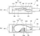
図11に、光ファイバの余長部分を収容することができるハウジングを有した従来の光電気複合型コネクタの一例を示す。図11の(a)は、この従来のコネクタの側断面図、(b)は、その平断面図である。この光電気複合コネクタ100は、回路基板108と、この回路基板108の上に設けた副基板115上の光電変換部109や配線117、これら回路基板108やその上の各種機器を収容することができるハウジング111、更に、外部機器接続用の電気ピン105を備える。光電変換部109には、光ケーブル104から引き出されてハウジング111内に湾曲部112cを有して配線された光ファイバ102が光学的に接続されており、ハウジング111は、この光電変換部109を収容する第1の収容体119の他、第2の収容体120を有する。光ファイバ102は、第1の収容体119を経て第2の収容体120に導入され、湾曲部112cでその向きを反転させて光電変換部109に向かって配線される。更に、湾曲部112cを曲げ弾性力に抗して挟んで保持できるように、第2の収容体120は、一対の側板部120d、120eを有している。 FIG. 11 shows an example of a conventional combined optical and electrical connector having a housing that can accommodate the extra length of the optical fiber. FIG. 11A is a side sectional view of this conventional connector, and FIG. 11B is a plan sectional view thereof. The
この従来構成では、光ファイバ102の余長部分113は、回路基板108の一方の側、特に、副基板115や各種機器が設けられた上側に設けることとされており、その一方で、回路基板108の他方の側、即ち、副基板115や各種機器が設けられた下側の、比較的大きな空間には、光ファイバ102の余長部分113は全く配置されていない。尚、回路基板108の下側に現れている線は電線103を示しているのであって、光ファイバ102を示すものではなく、回路基板108の下側に、光ファイバは存在しない。 In this conventional configuration, the
本願発明はこのような従来技術における問題点を解決するためになされたものであり、配線設計を複雑にすることなく、光ファイバの余長部分を収容することができるハウジングを備えた光電気複合型コネクタを提供することを目的とする。また、光電気複合型コネクタの内部空間を有効活用することができる光電気複合型コネクタを提供することを目的とする。 The present invention has been made to solve such problems in the prior art, and is an opto-electric composite having a housing that can accommodate the extra length of the optical fiber without complicating the wiring design. An object is to provide a mold connector. It is another object of the present invention to provide a photoelectric composite connector that can effectively utilize the internal space of the photoelectric composite connector.
本発明は、光ファイバを収容することができるハウジングを備えた光電気複合型コネクタであって、前記ハウジング内のスペースを上下に仕切る仕切部材を有し、前記光ファイバは、前記ハウジングの前後方向における一の側において前記ハウジング内に取り込まれるようになっており、前記仕切部材によって仕切られた前記ハウジング内の一のスペースに、前記ハウジングの前記一の側に位置する前記光ファイバの少なくとも一部が湾曲された状態で収容され、前記仕切部材によって仕切られた前記ハウジング内の他のスペースに、前記一のスペースに収容された少なくとも一部以外の前記光ファイバの湾曲部の一部であって、前記ハウジング内の一のスペースに収容された前記光ファイバの湾曲部に対して前記ハウジングの前記一の側とは前記ハウジングの前後方向において反対側に位置する前記光ファイバの他の少なくとも一部が収容されており、前記一のスペースに収容された、前記光ファイバの少なくとも一部と、前記他のスペースに収容された、前記光ファイバの他の少なくとも一部が、前記ハウジングの左右側の内壁と前記仕切部材の左右側の縁との間に形成された隙間を通じて連続しており、前記光電気複合型コネクタは更に、前記光ファイバの一端に接続された光電気変換モジュールと、前記仕切部材の前記他のスペース側であって前記ハウジングの前後方向において前記隙間に対応する位置に設けられた、前記光電気変換モジュールと電気的に接続され得る接続コネクタと、を備えることを特徴とする。
この構成によれば、仕切部材を利用して、ハウジングの内部を一のスペースと他のスペースとに明確に区分し、配線設計と光ファイバの収容部分とを明確に区別することにより、配線設計を複雑にすることなく、光ファイバの余長部分を収容することができる。また、光電気変換モジュールと電気コネクタを介して、光ファイバと光電気複合型コネクタを接続することにより、それらを直に接続する場合に比べて、接続作業或いは組立作業を容易にすることができる。The present invention is an optical / electrical connector having a housing that can accommodate an optical fiber, and has a partition member thatvertically partitions a space in the housing, and the optical fiber is afront-rear direction of the housing are adapted to be incorporated within the housing in one side ofthe said one space within said housing partitioned by the partition member, at least a portion of the optical fiber located onsaid one side of said housing Is part of the curved portion of the optical fiber other than at least a part of the one space accommodated in the other space in the housing which is accommodated in a curved state and partitioned by the partition member. , andthe one side of said housing with respect to the curved portion of said optical fiber housed in one space within said housing Another is at least partially housed in the optical fiber located on the opposite sidein the longitudinal direction of the housing,which is accommodated in said one space, at least a portion of said optical fiber, accommodated in the other space And at least a part of the optical fiber is continuous through a gap formed between the left and right inner walls of the housing and the left and right edges of the partition member, and the composite photoelectric connector And a photoelectric conversion module connected to one end of the optical fiber, and the photoelectric module provided at aposition corresponding to the gap in the front-rear direction of the housing on the other space sideof the partition member. And a connection connector that can be electrically connected to the conversion module.
According to this configuration, by using the partition member, the interior of the housing is clearly divided into one space and another space, and the wiring design and the optical fiber housing portion are clearly distinguished, thereby providing the wiring design. The extra length of the optical fiber can be accommodated without complicating the process. Further, by connecting the optical fiber and the photoelectric composite connector via the photoelectric conversion module and the electrical connector, the connection work or the assembly work can be facilitated as compared with the case of connecting them directly. .
上記光電気複合型コネクタにおいて、前記仕切部材は、前記光ファイバの前記湾曲部が形成する面と並列に前記ハウジング内のスペースを仕切るのが好ましい。
基板の向きを、光ファイバの湾曲部が形成する面と並列にすることにより、湾曲部を収容するためのスペースをより小さくすることができ、ハウジングの内部空間を有効活用することができる。In the photoelectric composite connector, it is preferable that the partition member partitions a space in the housing in parallel with a surface formed by the curved portion of the optical fiber.
By aligning the direction of the substrate in parallel with the surface formed by the curved portion of the optical fiber, the space for accommodating the curved portion can be further reduced, and the internal space of the housing can be effectively utilized.
前記隙間は、前記仕切部材の仕切り方向において、前記光電気複合型コネクタと相手コネクタとの嵌合側以外の側に設けられているのが好ましい。
このような側に隙間を設けることにより、光電気複合型コネクタと相手コネクタとの嵌合を妨げることなく、一のスペースと他のスペースとの間で、光ファイバを連続した状態とすることができる。The gap, the in partition direction of the partition member, preferably provided on the side of the non-fitting side of the photoelectric composite connectorand phase hand connector.
By providing a gap on such a side, it is possible to keep the optical fiber continuous between one space and another space without hindering the fitting between the photoelectric composite connector and the mating connector. it can.
上記光電気複合型コネクタにおいて、前記光ファイバの少なくとも一部が、前記一のスペースに設けられた巻付け部に巻き付けられていてもよい。
巻付け部を設けることにより、光ファイバを容易に収容することができる。
また、上記光電気複合型コネクタにおいて、前記接続コネクタは、前記光ファイバの他の少なくとも一部よりも、前記一の側に近い側に配置されていてもよい。In the photoelectric composite connector, at least a part of theoptical fiber may be wound around a winding portion provided in the one space.
By providing the winding portion, the optical fiber can be easily accommodated.
Moreover, the said optoelectric composite connector WHEREIN: The said connection connector may be arrange | positioned at the side near the said one side rather than at least one part of the said optical fiber.
本願発明によれば、配線設計を複雑にすることなく、光ファイバの余長部分を収容することができるハウジングを備えた光電気複合型コネクタが提供される。また、光電気複合型コネクタの内部空間を有効活用することができる光電気複合型コネクタが提供される。 According to the present invention, there is provided an optical / electrical connector having a housing capable of accommodating an extra length portion of an optical fiber without complicating wiring design. In addition, a composite photoelectric connector that can effectively use the internal space of the composite photoelectric connector is provided.
添付図面を参照しつつ、本発明の好適な一つの実施形態による光電気複合型コネクタについて説明する。 With reference to the accompanying drawings, a photoelectric composite connector according to a preferred embodiment of the present invention will be described.
図1に、本発明による光電気複合コネクタ1の斜視図を示し、更に、図2に、この光電気複合コネクタ1を接続相手である電気コネクタ2とともに、斜視図(図2の(a))と中心線断面図(図2の(b))で示す。光電気複合コネクタ1は、光ケーブル10の一端に固定した状態で使用され、光信号を処理することができるが、光電気複合コネクタ1の接続相手は、光コネクタではなく電気コネクタである。電気コネクタ2は、基板3に設置した状態で使用され、コネクタ2との実際の嵌合時には、光電気複合型コネクタ1の先端側に一部突出させた状態で設けたコネクタ嵌合部46が、基板3に直立した電気コネクタ2の嵌合穴4に挿入される。光信号と電気信号の変換は、光電気複合型コネクタ1で行う。光ケーブル10を通じて光電気複合コネクタ1で受信された光信号は、光電気複合コネクタ1において電気信号に変換された後に、電気コネクタ2へ送信され、或いは、電気コネクタ2を通じて光電気複合コネクタ1で受信された電気信号は、光電気複合コネクタ1において光信号に変換された後に、光ケーブル10へ送信される。 FIG. 1 is a perspective view of an optoelectric
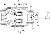
図3に、図1の光電気複合コネクタ1から蓋45を取り除いた状態を斜視図で示し、更に、図4に、図1のA−A線断面図を、図5に、図1の光電気複合コネクタ1の横断面図を、図6に、図1のB−B線断面図を、それぞれ示す。蓋45は、光電気複合コネクタ1と電気コネクタ2との嵌合方向(図3の矢印「ア」方向)に沿って、光電気複合コネクタ1に対してスライド移動させることによって、光電気複合コネクタ1のハウジング20に着脱自在に取り付けることができる。ハウジング20に取り付けられた際、蓋45の一部は、上述したコネクタ嵌合部46の一部を形成し得る。また、蓋45を光電気複合コネクタ1に対してスライド移動させたとき、基板50の先端部51は、コネクタ嵌合部46に挿入され、その下側に収容空間58を残した状態で、コネクタ嵌合部46の天井側内壁に位置決めされる。基板50の先端部51裏面には、複数の電気パッド57(便宜上、点線で示す)が所定ピッチで一列に配列されている。図面上明らかではないが、これらの電気パッド57は、光ケーブル10の各光ファイバ11に対応して設けられており、光ファイバ11の光信号に対応する電気信号の伝達を行う。光電気複合コネクタ1と電気コネクタ2(図2参照)との嵌合時には、光電気複合コネクタ1のコネクタ嵌合部46が、電気コネクタ2の嵌合穴4(図2の(b)参照)に挿入されるとともに、光電気複合コネクタ1のコネクタ嵌合部46に設けた収容空間58に、電気コネクタ2の基部5(図2の(b)参照)が収容される。このとき、基板50の先端部51裏面に設けた電気パッド57(接触部)が、電気コネクタ2に設けた対応する相手側端子6の接点7と電気的に接続され、光電気複合コネクタ1と電気コネクタ2(図2参照)との間の電気通信が可能となる。 3 is a perspective view showing a state in which the
図4によく示されるように、蓋45をハウジング20に取り付けたとき、蓋45の嵌合側に設けた前側突出部48と、ハウジング20の嵌合側に設けた前側突出部23が対応し、また、蓋45の光ケーブル10側に設けた後側突出部49と、ハウジング20の嵌合側に設けた後側突出部39が対応する。これにより、蓋45をハウジング20に対して位置決めするとともにハウジング20の収容空間を閉じる。ハウジング20からの蓋45の抜け落ちを防ぐため、図5によく示されるように、蓋45の外壁にロック突部47を、ハウジング20の内壁に対応ロック突部37を、それぞれ設けて、蓋45とハウジング20をロック可能としてある。尚、光コネクタ1における信号状態を確認できるように、図6に示すように、ハウジング20の外部から一部視認可能な状態で、基板50の後端側に導光板40を設けてもよい。導光板40を通じて外部に光を発するようにして、光電気複合コネクタ1における信号の伝達状態をユーザに知らせることもできる。 As shown in FIG. 4, when the
ハウジング20内のスペースは、その内部に設置された基板50によって、上段スペース33と下段スペース34に仕切られている。下段スペース34には、主に、光ケーブル10から取り出された光ファイバ11の少なくとも一部(後述する図7乃至10に示す湾曲部15)、換言すれば、光ファイバ11の余長部分が収容され、一方、上段スペース33には、主に、下段スペース34に収容された部分(湾曲部15)以外の、光ファイバ11の他の一部17や、光ファイバ11の一端に接続された光電気変換モジュール14、更に、基板50に固定された、光電気変換モジュール14と接続され得る接続コネクタ54が収容される。 A space in the
ハウジング20の内部において、基板50の中央付近は、ハウジング20のケーブル抑え部26の上面に載置され、その後端側55は、ハウジング20の基板載置部24に載置される。基板50の先端部51は、既に説明したように、コネクタ嵌合部46に挿入されて支持される。基板50の幅方向は、ハウジング20の基板位置決め突起25によって規制されるとともに、コネクタ嵌合部46に、基板50の先端部51が挿入、配置されることにより位置決めされるようになっている。 Inside the
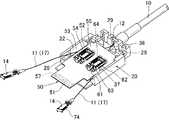
図7は、図3の光電気複合コネクタ1から更に基板50を取り除いた状態を示す斜視図である。光ケーブル10の光ファイバ取出口は、固定金具12によってクランプされる。クランプされた固定金具12は、ハウジング20に設けた側面視略U字状の金具保持部29に上方から挿入されることによってハウジング20に容易に固定される。金具保持部29は、1つに限らず、ハウジング20の複数位置から選択可能な状態で複数設けることができる。使用環境に応じて、適当な位置の金具保持部29を選択して使用することにより、光ケーブル10や光ファイバ11の出口方向を制御し、装置内の配線設計を容易にすることができる。例えば、図7に示した中央位置に設けた金具保持部29Aに代えて、図8に示した側面位置に設けた金具保持部29B(ここでは、正面から見て右側の金具保持部29B)に、固定金具12を装着することにより、光ケーブル10や光ファイバ11をハウジング20に対して横向きに固定することもできる。 FIG. 7 is a perspective view showing a state where the
図7、8によく示されるように、光ケーブル10から取り出した光ファイバ11は、ハウジング20の光ケーブル10側に設けた導入口38から下段スペース34へ案内される。光ファイバ11がスムーズに案内されるように、導入口38の側壁はR状としておくのが好ましい。特に、図8に示す例のように、側面位置に設けた金具保持部29Bを利用して固定金具12が装着された場合には、光ファイバ11の方向を大きく変更する必要が生じ、この結果、導入口38の側壁と衝突し易い状態となるが、この場合でも、導入口38の側壁がRを形成していれば、光ファイバ11を下段スペース34へとスムーズに案内することができる。 As shown well in FIGS. 7 and 8, the
光ケーブル10から取り出された光ファイバ11の少なくとも一部は、下段スペース34に湾曲された状態で収容される。光ファイバ11はガラス繊維であるため、急な曲げを形成することはできず、比較的大きな湾曲部を形成した状態で収容させる必要がある。湾曲部15を設けることにより、光ファイバ11を、より安全に、且つ、小スペースで、下段スペース34に収容することができる。 At least a part of the
収容作業を容易にするため、下段スペース34に円環状の巻付け部27を設けてもよい。巻付け部27の周囲には、更に、基板50を載置するためにも使用される、略L字状のケーブル抑え部26が複数、ここでは3つ設けられている。下段スペース34に案内した光ファイバ11は、接続コネクタ54に対する取付け時の作業しろを十分に確保した状態で、巻付け部27に巻き付けられ、更に、ケーブル抑え部26によって、上方から抑えられる。巻付け部27を利用することにより、湾曲部15を、よりコンパクトに、且つ、より簡単に、下段スペース34に配置することができ、更に、ケーブル抑え部26を利用することにより、湾曲部15の上段スペース33側への拡がりを防止することができる。但し、これら巻付け部27やケーブル抑え部26を使用することなく、ハウジング20の内壁22を利用して、湾曲部15を形成してもよい。尚、湾曲部15は、必ずしも、巻き付け部27に巻き付けられるような長さを必要とするものではなく、例えば、湾曲部15の弧のほんの一部と接触する程度の長さしか有しないものであっても勿論よい。 An annular winding
図7、図8に加えて、図9、図10、及び図3をも参照して、光電気複合コネクタ1の組立方法を説明する。ここで図9、図10、及び図3は、図7、図8の状態とした後の、光電気複合コネクタ1の組立工程を段階的に示したものと考えてよい。 A method for assembling the optoelectric
図7、図8に示すように、光ファイバ11の湾曲部15を、ハウジング20に配置した後、図9に示すように、この湾曲部15の上部に基板50を設置する。基板50が設置されることにより、ハウジング20内のスペースは、上段スペース33と下段スペース34に仕切られ、この結果、湾曲部15は、下段スペース34に収容されることになる。このように、基板50を利用して、ハウジング20の内部を上段スペース33と下段スペース34とに区分し、配線設計と光ファイバの収容部分とを明確に区分けすることにより、配線設計を複雑にすることなく、光ファイバの余長部分を収容することができる。また、基板50の向きを、光ファイバ11の湾曲部15が形成する面16と並列にすることにより、湾曲部15を収容するためのスペースをより小さくすることができ、ハウジング20の内部空間を有効活用することができる。 As shown in FIGS. 7 and 8, after the bending
図9に示すように、基板50によってハウジング20が上段スペース33と下段スペース34に仕切られた後も、下段スペース34に収容された、光ファイバ11の湾曲部15と、上段スペース33に収容された、光ファイバ11の一部17とは、ハウジング20の内壁22と基板50の縁52との間に形成された隙間53を通じて連続状態を維持する。本実施形態では、この隙間53は、仕切部材50の仕切り方向において、光電気複合コネクタ1と相手コネクタとの嵌合側(光電気複合コネクタ1の先端側)以外の側、例えば、嵌合方向に沿った側に設けられる。仮に、隙間が、光電気複合コネクタ1と相手コネクタとの嵌合側(光電気複合コネクタ1の先端側)に設けられている場合には、ハウジング20の内部における、光電気複合コネクタ1と相手コネクタとの嵌合側の領域が、光ファイバ11によって占有されてしまうため、嵌合に支障が生じ、また、これを避けるためにコネクタが大型化するおそれがある。図9に示すように、光電気複合コネクタ1と相手コネクタとの嵌合側以外の側に隙間53を設けることにより、光電気複合コネクタ1と相手コネクタとの嵌合を妨げることなく、容易に、上段スペース33と下段スペース34との間で、光ファイバ11を連続した状態とすることができる。尚、隙間を嵌合側に設けることは必ずしも許されないというわけではなく、コネクタ嵌合部46に挿入される基板50の先端部51に光ファイバ11が及ばないのであれば、嵌合側に設けてもよい。 As shown in FIG. 9, even after the
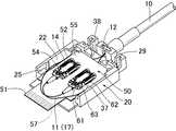
その後、図10に示すように、隙間53から取り出された光ファイバ11は、半弧を描くように大きく湾曲させた状態で、光ファイバ11の一端に接続された光電気変換モジュール14を利用して、基板50上の接続コネクタ54に接続される。これら光電気変換モジュール14と接続コネクタ54との間の接続は電気接続である。光信号と電気信号の変換は、光電気変換モジュール14で行われる。電気接続させるため、光電気変換モジュール14は、接続コネクタ54の凹状の嵌合部64に嵌め込まれる。嵌合部64に嵌め込まれても、固定されるわけではなく、その後も自由に着脱させることができる。 Thereafter, as shown in FIG. 10, the
光電気変換モジュール14は、様々な光電気交換部品を備えることによって、電気・光変換機能(送信機能と捉えることもできる)と、光・電気変換機能(受信機能と捉えることもできる)の双方を有する。例えば、接続コネクタ54と光電気変換モジュール14の嵌合時には、光電気変換モジュール14に設けた光電気変換部品の働きによって、光ケーブル10を通じて伝達された光信号を電気信号に変換して、接続コネクタ54や基板50に伝達し、或いは、基板50を通じて伝達された電気信号を光信号に変換して、光ケーブル10に伝達する。 The
これに対し、接続コネクタ54は、形状は多少特種なものであるものの、機能は一般的な電気コネクタと全く同じである。接続コネクタ54は、主に、枠状のレセプタクルハウジング61と、これに設置される複数の端子62、更に、ハウジング61の外部を覆うシェル63を有する。レセプタクルハウジング61は枠状に形成されており、光電気変換モジュール14を嵌め込む嵌合部64(図9参照)を形成している。レセプタクルハウジング61に圧入固定されたレセプタクル端子62は、各々、それらの一部において嵌合部64に突出し、光電気変換モジュール14が嵌合部64に嵌め込まれた際に、光電気変換モジュール14側の対応端子74と電気的に接続され得る。 On the other hand, the
最後に、図3に示すように、ハウジング20に、蓋45をスライド移動させて取り付けることにより、光電気複合コネクタ1の組立完了となる。 Finally, as shown in FIG. 3, the assembly of the photoelectric
尚、基板50に設けた電気パッド57は、相手側の電気コネクタ2と必ずしも直接接続される必要はなく、電気パッド57に実装された他の電気コネクタを嵌合部として、これを介して、相手側の電気コネクタ2と電気接続されてもよい。 The
光ケーブルを接続して使用するタイプの光電気複合型コネクタに幅広く応用することができる。 The present invention can be widely applied to a composite photoelectric connector of a type that is used by connecting an optical cable.
1 光電気複合コネクタ
10 光ケーブル
11 光ファイバ
12 固定金具
14 光電気変換モジュール
15 湾曲部
16 面
20 ハウジング
22 内壁
27 巻付け部
33 上段スペース
34 下段スペース
50 基板
52 縁
53 隙間
54 接続コネクタDESCRIPTION OF
27
Claims (3)
Translated fromJapanese前記ハウジング内のスペースを上下に仕切る仕切部材を有し、
前記光ファイバは、前記ハウジングの前後方向における一の側において前記ハウジング内に取り込まれるようになっており、
前記仕切部材によって仕切られた前記ハウジング内の一のスペースに、前記ハウジングの前記一の側に位置する前記光ファイバの少なくとも一部が湾曲された状態で収容され、前記仕切部材によって仕切られた前記ハウジング内の他のスペースに、前記一のスペースに収容された少なくとも一部以外の前記光ファイバの湾曲部の一部であって、前記ハウジング内の一のスペースに収容された前記光ファイバの湾曲部に対して前記ハウジングの前記一の側とは前記ハウジングの前後方向において反対側に位置する前記光ファイバの他の少なくとも一部が収容されており、
前記一のスペースに収容された、前記光ファイバの少なくとも一部と、前記他のスペースに収容された、前記光ファイバの他の少なくとも一部が、前記ハウジングの左右側の内壁と前記仕切部材の左右側の縁との間に形成された隙間を通じて連続しており、
前記光電気複合型コネクタは更に、
前記光ファイバの一端に接続された光電気変換モジュールと、
前記仕切部材の前記他のスペース側であって前記ハウジングの前後方向において前記隙間に対応する位置に設けられた、前記光電気変換モジュールと電気的に接続され得る接続コネクタと、
を備えることを特徴とする光電気複合型コネクタ。An optical / electrical connector having a housing capable of accommodating an optical fiber,
A partition member forvertically dividing the space in the housing;
The optical fiber is adapted to be taken into the housing on one side in thefront-rear direction of the housing,
Wherein one of the space in the housing partitioned by the partition member, at least a portion of the optical fiber located onsaid one side of the housing is accommodated in a state of being curved, partitioned by the partition member and the In another space in the housing, a portion of the bending portion of the optical fiber other than at least a portion housed in the one space, and the bending of the optical fiber housed in the one space in the housing wherein thesaid one side of the housing other are at least partially housed in the optical fiber located on the opposite sidein the longitudinal direction of the housing relative to the part,
At least a part of the optical fiber housed in the one space and at least another part of the optical fiber housed in the other space are formed on the inner wall on the left and right sides of the housing and the partition member. It is continuous through the gap formed between the left and right edges,
The photoelectric composite connector further includes:
A photoelectric conversion module connected to one end of the optical fiber;
A connection connector that can be electrically connected to the photoelectric conversion module, provided at aposition corresponding to the gap in the front-rear direction of the housing on the other space sideof the partition member;
An opto-electric composite connector comprising:
Priority Applications (2)
| Application Number | Priority Date | Filing Date | Title |
|---|---|---|---|
| JP2013177666AJP6012565B2 (en) | 2013-08-29 | 2013-08-29 | Photoelectric composite connector |
| US14/463,731US9523827B2 (en) | 2013-08-29 | 2014-08-20 | Optical-electrical composite connector |
Applications Claiming Priority (1)
| Application Number | Priority Date | Filing Date | Title |
|---|---|---|---|
| JP2013177666AJP6012565B2 (en) | 2013-08-29 | 2013-08-29 | Photoelectric composite connector |
Publications (2)
| Publication Number | Publication Date |
|---|---|
| JP2015045787A JP2015045787A (en) | 2015-03-12 |
| JP6012565B2true JP6012565B2 (en) | 2016-10-25 |
Family
ID=52583397
Family Applications (1)
| Application Number | Title | Priority Date | Filing Date |
|---|---|---|---|
| JP2013177666AActiveJP6012565B2 (en) | 2013-08-29 | 2013-08-29 | Photoelectric composite connector |
Country Status (2)
| Country | Link |
|---|---|
| US (1) | US9523827B2 (en) |
| JP (1) | JP6012565B2 (en) |
Families Citing this family (8)
| Publication number | Priority date | Publication date | Assignee | Title |
|---|---|---|---|---|
| CN107710044B (en)* | 2015-06-15 | 2019-12-31 | 日本电气株式会社 | Pluggable Optical Module and Optical Communication System |
| JP2017090657A (en) | 2015-11-10 | 2017-05-25 | ヒロセ電機株式会社 | Connector with optical fiber cable |
| JP6682974B2 (en)* | 2016-04-14 | 2020-04-15 | 住友電気工業株式会社 | Optical transceiver |
| CN106936006A (en)* | 2017-03-06 | 2017-07-07 | 中航光电科技股份有限公司 | Active optical cable component and its connector |
| US20190204518A1 (en)* | 2017-12-28 | 2019-07-04 | Kui-Hsien Huang | Fiber transmission device |
| US11125958B2 (en)* | 2018-03-16 | 2021-09-21 | TE Connectivity Services Gmbh | Optical pluggable module for a communication system |
| EP3844547A1 (en)* | 2018-08-31 | 2021-07-07 | CommScope Connectivity Belgium BVBA | Frame assemblies for optical fiber distribution elements |
| CN114077020A (en)* | 2020-08-18 | 2022-02-22 | 华为技术有限公司 | Composite module and method of making the same |
Family Cites Families (14)
| Publication number | Priority date | Publication date | Assignee | Title |
|---|---|---|---|---|
| EP0533110B1 (en)* | 1991-09-19 | 1995-03-15 | Eastman Kodak Company | Laser diode with card-edge connector |
| JP3008879B2 (en)* | 1997-02-26 | 2000-02-14 | 日本電気株式会社 | Lightwave circuit mounting structure |
| JP3910815B2 (en)* | 2001-09-07 | 2007-04-25 | 富士通株式会社 | Optical unit |
| JP4238187B2 (en)* | 2004-07-21 | 2009-03-11 | ヒロセ電機株式会社 | Photoelectric composite connector and board using the same |
| US7393147B1 (en)* | 2007-01-10 | 2008-07-01 | Raytheon Company | Optical to electrical backshell connector |
| US7756379B2 (en)* | 2007-08-06 | 2010-07-13 | Adc Telecommunications, Inc. | Fiber optic enclosure with internal cable spool |
| JP5157393B2 (en)* | 2007-11-29 | 2013-03-06 | 住友電気工業株式会社 | Optical module and cable unit with optical module |
| JP2009198603A (en)* | 2008-02-19 | 2009-09-03 | Mitsumi Electric Co Ltd | Optical terminating device |
| US9052477B2 (en)* | 2009-10-29 | 2015-06-09 | Sumitomo Electric Industries, Ltd. | Optical transceiver with inner fiber set within tray securing thermal path from electronic device to housing |
| TWI408431B (en)* | 2010-02-26 | 2013-09-11 | Connection Technology Systems Inc | Fiber communication conversion device and the installing method therefor |
| AU2010355632B2 (en)* | 2010-06-18 | 2014-09-18 | Adc Communications (Shanghai) Co., Ltd. | Fiber optic distribution terminal and method of deploying fiber distribution cable |
| JP2012088571A (en)* | 2010-10-20 | 2012-05-10 | Fujikura Ltd | Optoelectric composite connector and cable with connector |
| WO2013052748A2 (en)* | 2011-10-05 | 2013-04-11 | Corning Cable Systems Llc | Fiber optic connector assemblies having a reverse optical fiber loop |
| JP5621862B2 (en)* | 2013-02-27 | 2014-11-12 | ヒロセ電機株式会社 | Photoelectric composite connector |
- 2013
- 2013-08-29JPJP2013177666Apatent/JP6012565B2/enactiveActive
- 2014
- 2014-08-20USUS14/463,731patent/US9523827B2/enactiveActive
Also Published As
| Publication number | Publication date |
|---|---|
| US9523827B2 (en) | 2016-12-20 |
| JP2015045787A (en) | 2015-03-12 |
| US20150063763A1 (en) | 2015-03-05 |
Similar Documents
| Publication | Publication Date | Title |
|---|---|---|
| JP6012565B2 (en) | Photoelectric composite connector | |
| TWI527316B (en) | Cage and connector cover for a receptacle assembly | |
| TWI416809B (en) | Connector | |
| CN103262353B (en) | Plug-in connectors for high data transmission rates | |
| JP2023508309A (en) | Connector assembly and optical-electrical composite connector | |
| US9363020B2 (en) | Optical transceiver having inner fibers for coupling optical receptacle with transmitter and receiver modules | |
| JP2020098249A (en) | Optical transceiver | |
| JP2021120704A (en) | Optical transceiver | |
| JP2009198603A (en) | Optical terminating device | |
| JP6409630B2 (en) | Optical transceiver | |
| JP6523802B2 (en) | Transceiver module plug connector | |
| JP2011209683A (en) | Optical transceiver | |
| JP2017227727A (en) | Optical transceiver | |
| TW201345064A (en) | Die cast cage for a receptacle assembly | |
| JP4297279B2 (en) | Optical connector | |
| JP2006215276A (en) | Optical connector | |
| CN111133353B (en) | Optical connector device | |
| JP3654574B2 (en) | Hybrid connector support structure | |
| JP5886670B2 (en) | Optical receiver terminal mounting structure | |
| JP2020134880A (en) | Optical connector | |
| JP6278627B2 (en) | Optical module | |
| KR20180102718A (en) | Optical communication module | |
| JP5653661B2 (en) | Optical line housing structure | |
| JP2009198602A (en) | Optical terminating device | |
| JP2015032556A (en) | Optical connector |
Legal Events
| Date | Code | Title | Description |
|---|---|---|---|
| A621 | Written request for application examination | Free format text:JAPANESE INTERMEDIATE CODE: A621 Effective date:20150417 | |
| A977 | Report on retrieval | Free format text:JAPANESE INTERMEDIATE CODE: A971007 Effective date:20150723 | |
| A131 | Notification of reasons for refusal | Free format text:JAPANESE INTERMEDIATE CODE: A131 Effective date:20150727 | |
| A521 | Request for written amendment filed | Free format text:JAPANESE INTERMEDIATE CODE: A523 Effective date:20150924 | |
| A02 | Decision of refusal | Free format text:JAPANESE INTERMEDIATE CODE: A02 Effective date:20160404 | |
| A521 | Request for written amendment filed | Free format text:JAPANESE INTERMEDIATE CODE: A523 Effective date:20160629 | |
| A911 | Transfer to examiner for re-examination before appeal (zenchi) | Free format text:JAPANESE INTERMEDIATE CODE: A911 Effective date:20160706 | |
| TRDD | Decision of grant or rejection written | ||
| A01 | Written decision to grant a patent or to grant a registration (utility model) | Free format text:JAPANESE INTERMEDIATE CODE: A01 Effective date:20160912 | |
| A61 | First payment of annual fees (during grant procedure) | Free format text:JAPANESE INTERMEDIATE CODE: A61 Effective date:20160920 | |
| R150 | Certificate of patent or registration of utility model | Ref document number:6012565 Country of ref document:JP Free format text:JAPANESE INTERMEDIATE CODE: R150 | |
| R157 | Certificate of patent or utility model (correction) | Free format text:JAPANESE INTERMEDIATE CODE: R157 | |
| R250 | Receipt of annual fees | Free format text:JAPANESE INTERMEDIATE CODE: R250 | |
| R250 | Receipt of annual fees | Free format text:JAPANESE INTERMEDIATE CODE: R250 | |
| S531 | Written request for registration of change of domicile | Free format text:JAPANESE INTERMEDIATE CODE: R313531 | |
| R350 | Written notification of registration of transfer | Free format text:JAPANESE INTERMEDIATE CODE: R350 | |
| R250 | Receipt of annual fees | Free format text:JAPANESE INTERMEDIATE CODE: R250 | |
| R250 | Receipt of annual fees | Free format text:JAPANESE INTERMEDIATE CODE: R250 | |
| R250 | Receipt of annual fees | Free format text:JAPANESE INTERMEDIATE CODE: R250 | |
| R250 | Receipt of annual fees | Free format text:JAPANESE INTERMEDIATE CODE: R250 | |
| R250 | Receipt of annual fees | Free format text:JAPANESE INTERMEDIATE CODE: R250 |