JP6010763B2 - Electrochemical capacitor - Google Patents
Electrochemical capacitorDownload PDFInfo
- Publication number
- JP6010763B2 JP6010763B2JP2012557843AJP2012557843AJP6010763B2JP 6010763 B2JP6010763 B2JP 6010763B2JP 2012557843 AJP2012557843 AJP 2012557843AJP 2012557843 AJP2012557843 AJP 2012557843AJP 6010763 B2JP6010763 B2JP 6010763B2
- Authority
- JP
- Japan
- Prior art keywords
- negative electrode
- electrochemical capacitor
- electrode layer
- electrolytic solution
- solvent
- Prior art date
- Legal status (The legal status is an assumption and is not a legal conclusion. Google has not performed a legal analysis and makes no representation as to the accuracy of the status listed.)
- Expired - Fee Related
Links
Images


Classifications
- H—ELECTRICITY
- H01—ELECTRIC ELEMENTS
- H01G—CAPACITORS; CAPACITORS, RECTIFIERS, DETECTORS, SWITCHING DEVICES, LIGHT-SENSITIVE OR TEMPERATURE-SENSITIVE DEVICES OF THE ELECTROLYTIC TYPE
- H01G9/00—Electrolytic capacitors, rectifiers, detectors, switching devices, light-sensitive or temperature-sensitive devices; Processes of their manufacture
- H01G9/004—Details
- H01G9/022—Electrolytes; Absorbents
- H01G9/025—Solid electrolytes
- H01G9/028—Organic semiconducting electrolytes, e.g. TCNQ
- H—ELECTRICITY
- H01—ELECTRIC ELEMENTS
- H01G—CAPACITORS; CAPACITORS, RECTIFIERS, DETECTORS, SWITCHING DEVICES, LIGHT-SENSITIVE OR TEMPERATURE-SENSITIVE DEVICES OF THE ELECTROLYTIC TYPE
- H01G11/00—Hybrid capacitors, i.e. capacitors having different positive and negative electrodes; Electric double-layer [EDL] capacitors; Processes for the manufacture thereof or of parts thereof
- H01G11/54—Electrolytes
- H01G11/58—Liquid electrolytes
- Y—GENERAL TAGGING OF NEW TECHNOLOGICAL DEVELOPMENTS; GENERAL TAGGING OF CROSS-SECTIONAL TECHNOLOGIES SPANNING OVER SEVERAL SECTIONS OF THE IPC; TECHNICAL SUBJECTS COVERED BY FORMER USPC CROSS-REFERENCE ART COLLECTIONS [XRACs] AND DIGESTS
- Y02—TECHNOLOGIES OR APPLICATIONS FOR MITIGATION OR ADAPTATION AGAINST CLIMATE CHANGE
- Y02E—REDUCTION OF GREENHOUSE GAS [GHG] EMISSIONS, RELATED TO ENERGY GENERATION, TRANSMISSION OR DISTRIBUTION
- Y02E60/00—Enabling technologies; Technologies with a potential or indirect contribution to GHG emissions mitigation
- Y02E60/13—Energy storage using capacitors
- Y—GENERAL TAGGING OF NEW TECHNOLOGICAL DEVELOPMENTS; GENERAL TAGGING OF CROSS-SECTIONAL TECHNOLOGIES SPANNING OVER SEVERAL SECTIONS OF THE IPC; TECHNICAL SUBJECTS COVERED BY FORMER USPC CROSS-REFERENCE ART COLLECTIONS [XRACs] AND DIGESTS
- Y02—TECHNOLOGIES OR APPLICATIONS FOR MITIGATION OR ADAPTATION AGAINST CLIMATE CHANGE
- Y02T—CLIMATE CHANGE MITIGATION TECHNOLOGIES RELATED TO TRANSPORTATION
- Y02T10/00—Road transport of goods or passengers
- Y02T10/60—Other road transportation technologies with climate change mitigation effect
- Y02T10/70—Energy storage systems for electromobility, e.g. batteries
Landscapes
- Chemical & Material Sciences (AREA)
- Chemical Kinetics & Catalysis (AREA)
- Electrochemistry (AREA)
- Engineering & Computer Science (AREA)
- Power Engineering (AREA)
- Microelectronics & Electronic Packaging (AREA)
- Electric Double-Layer Capacitors Or The Like (AREA)
Description
Translated fromJapanese本発明は各種電子機器、ハイブリッド自動車や燃料電池車におけるバックアップ電源回生、あるいは電力貯蔵等の用途で利用される電気化学キャパシタに関する。 The present invention relates to an electrochemical capacitor used in various electronic devices, backup power source regeneration or power storage in hybrid vehicles and fuel cell vehicles.
図5Aは、従来の電気化学キャパシタの水平断面図である。図5Bは従来の電気化学キャパシタにおける電極巻回ユニット100の部分切り欠き正面図である。 FIG. 5A is a horizontal cross-sectional view of a conventional electrochemical capacitor. FIG. 5B is a partially cutaway front view of
従来の電気化学キャパシタは、電極巻回ユニット100とリチウム金属(リチウム極)104、105と、外装容器106とを有する。電極巻回ユニット100は、正極101と、負極102とをそれらの間にセパレータ103を介在させた状態で積層して同心的に巻回して形成される。リチウム金属104、105は、電極巻回ユニット100の外周部及び中心部に、リチウムイオン供給源として、それぞれ配置されている。電極巻回ユニット100、リチウム金属104、105及び電解液(図示せず)が、アルミニウム製または鉄製の外装容器106内に収容されている。 The conventional electrochemical capacitor includes an
また、正極101及び負極102は、表裏面を貫通する孔が設けられた多孔材からなる後述の集電体を芯材として形成されている。集電体を多孔材にすることによって、リチウム金属104、105が電極巻回ユニット100の外周部と中心部に別々に配置されていても、リチウムイオンがリチウム金属104、105から正極101、負極102の各集電体の貫通孔を通って自由に移動できる。これにより、電極巻回ユニット100の負極102のすべての箇所にリチウムイオンを予めドーピング(プレドープ)できる。Further, the
正極101と負極102の夫々の集電体へ電極端子107、108が接続されている。電極端子107、108は、円筒状の電極巻回ユニット100の巻回軸方向に沿って互いに逆方向側に引き出されている。電極巻回ユニット100の中心部に形成されたリチウム金属105は管棒109により支持されている。管棒109は同時に電極巻回ユニット100の支持用の軸棒の役割も担っている。
電極巻回ユニット100の最外周面は巻回形状を保持するためにテープ110により固定されている。 The outermost peripheral surface of the
このように従来の電気化学キャパシタは、リチウムイオン供給源を電極巻回ユニット100の外周部と中心部の2箇所に設けることにより、1箇所のリチウムイオン供給源からリチウムイオンを供給してプレドープするよりも早くリチウムイオンを負極102へプレドープさせることができる。 As described above, the conventional electrochemical capacitor is pre-doped by supplying lithium ions from one lithium ion supply source by providing lithium ion supply sources at two locations, the outer peripheral portion and the central portion of the
なお、この出願に関する先行技術文献情報として、例えば特許文献1が知られている。 As prior art document information relating to this application, for example,
しかし、電気化学キャパシタを急速に繰り返し充放電させると、充放電中に負極の電位が上昇し、正負極間の電位差が低下する虞がある。これにより、電気化学キャパシタの単位体積あたりのエネルギー密度が低下する虞がある。 However, if the electrochemical capacitor is rapidly and repeatedly charged and discharged, the potential of the negative electrode increases during charging and discharging, and the potential difference between the positive and negative electrodes may decrease. Thereby, there exists a possibility that the energy density per unit volume of an electrochemical capacitor may fall.
また、負極の電位が上がることにより、予め負極の電極層内に吸蔵されたリチウムが負極外へ析出する虞がある。この析出したリチウムはセパレータなどを突き破り、短絡を引き起こす虞がある。 In addition, when the potential of the negative electrode is increased, lithium previously stored in the electrode layer of the negative electrode may be deposited outside the negative electrode. This precipitated lithium may break through the separator and the like and cause a short circuit.
本発明における電気化学キャパシタは、電解液とキャパシタ素子と外装体とを有する。電解液は、カチオンとアニオンとラクトン類以外からなる溶媒とラクトン類とを含む。キャパシタ素子は、負極と正極とセパレータとを有する。負極は、カチオンを吸蔵する電極層を有する。正極は、分極性電極層を有し負極と対向している。セパレータは、正極と負極との間に設けられている。負極と正極とセパレータとは積層または巻回されている。キャパシタ素子には、電解液が含浸されている。外装体は、電解液とキャパシタ素子とを収容している。電解液は、溶媒に対して0.001wt%以上、5wt%以下の前記ラクトン類を含む。 The electrochemical capacitor in the present invention includes an electrolytic solution, a capacitor element, and an exterior body. The electrolytic solution contains a solvent and lactones other than cations, anions and lactones. The capacitor element has a negative electrode, a positive electrode, and a separator. The negative electrode has an electrode layer that occludes cations. The positive electrode has a polarizable electrode layer and faces the negative electrode. The separator is provided between the positive electrode and the negative electrode. The negative electrode, the positive electrode, and the separator are laminated or wound. The capacitor element is impregnated with an electrolytic solution. The exterior body accommodates the electrolytic solution and the capacitor element. The electrolytic solution contains 0.001 wt% or more and 5 wt% or less of the lactone with respect to the solvent.
この構成により、急速な充放電中に生じる負極の電位変化を抑制することができ、電気化学キャパシタのキャパシタエネルギー密度を高めることができる。 With this configuration, the potential change of the negative electrode that occurs during rapid charge / discharge can be suppressed, and the capacitor energy density of the electrochemical capacitor can be increased.
図1は本発明の実施形態における電気化学キャパシタの切り欠き斜視図である。 FIG. 1 is a cutaway perspective view of an electrochemical capacitor according to an embodiment of the present invention.
電気化学キャパシタ200は、キャパシタ素子1と、電解液(図示せず)と、キャパシタ素子1及び電解液を収容した外装体である有底形状の外装ケース6と、を有する。キャパシタ素子1は、正極2と、正極2と対向するように設けられる負極3と、正極2と負極3との間に設けられるセパレータ4とを有する。正極2は、金属からなる集電体2aと、集電体2aの表面に形成された分極性電極2bとを有する。分極性電極層2bは、イオンを吸脱着する正極電極層としての活性炭などから成る。負極3は、銅から成る集電体3aと、集電体3aの表面に形成された、リチウムイオンを吸蔵した電極層としての負極電極層3bを有する。負極電極層3bは、層間を有した多層状の結晶構造を含む炭素材料を主として含む。正極2および負極3はそれらの間にセパレータ4を介在させた状態で、巻回されている。正極2および負極3の表面には電極引出端子としてリード線5a、5bがそれぞれ接続されている。外装ケース6の開口端部からリード線5a、5bが表出するように封口部材7が、外装ケース6に設けられることにより、電気化学キャパシタ200が封止される。 The
電気化学キャパシタ200の製造方法について説明する。なお、電気化学キャパシタ200の製造方法は、本願発明の構成を実現するための一例であり、本発明は下記の製造方法に限定されない。 A method for manufacturing the
まず、正極2を作製する正極作製工程を説明する。 First, a positive electrode manufacturing process for manufacturing the
集電体2aとして例えば厚み約15μmの高純度アルミニウム箔(Alを99%以上含有)を用いる。このアルミニウム箔を塩素系のエッチング液中で電解エッチングをしてその表面を粗面化する。 As the
分極性電極層2bを粗面化した集電体2aの表裏面へ形成する。分極性電極層2bを構成する材料として、活性炭、結着剤や導電助剤などを用いることができる。 The
活性炭として例えば平均粒径5μmのフェノール樹脂系活性炭を、結着剤として例えばカルボキシメチルセルロース(CMC)の水溶液を、導電助剤として例えばアセチレンブラックをそれぞれ用いる。活性炭と結着剤と導電助剤とを10:2:1の重量比で混合する。この混合物を混練機で練合して所定の粘度に調整しペーストを作製する。 For example, a phenol resin activated carbon having an average particle diameter of 5 μm is used as the activated carbon, an aqueous solution of carboxymethyl cellulose (CMC) is used as the binder, and acetylene black is used as the conductive assistant, for example. Activated carbon, a binder, and a conductive additive are mixed at a weight ratio of 10: 2: 1. This mixture is kneaded with a kneader to adjust to a predetermined viscosity to produce a paste.
このペーストを集電体2aの表裏面に塗布し、100℃の大気雰囲気中において乾燥する。これにより、厚み40μmの分極性電極層2bを形成する。その後、分極性電極層2bが形成された集電体2aに、所定の幅になるようスリット加工を施す。 This paste is applied to the front and back surfaces of the
さらに、集電体2a表裏面上に形成された分極性電極層2bの一部を取り除き、分極性電極層2bが取り除かれた部分の集電体2a表面にリード線5aを針かしめなどの方法で接続する。以上より、正極2が完成する。 Further, a part of the
次に、負極3を作製する負極作製工程を説明する。 Next, a negative electrode manufacturing process for manufacturing the
集電体3aとして、例えば厚さ約15μmの銅箔を用いる。集電体3a表裏面へ負極電極層3bを形成する。負極電極層3bを構成する材料として、リチウムイオンを可逆的に吸蔵及び放出できる炭素材料、例えば易黒鉛化炭素を用いる。導電助剤には正極2と同様に例えばアセチレンブラックを用いる。結着剤として例えばポリテトラフルオロエチレン(PTFE)とCMCとを重量比4:1で混合したものを用いる。 For example, a copper foil having a thickness of about 15 μm is used as the
水にCMC、アセチレンブラック、易黒鉛化炭素、PTFEを順番に投入し、攪拌して混練してペーストを作製する。この際、各材料の混合比は、易黒鉛化炭素と導電助剤と結着剤とを重量比8:1:1となるようにする。 CMC, acetylene black, graphitizable carbon, and PTFE are sequentially added to water and stirred to knead to prepare a paste. At this time, the mixing ratio of the respective materials is set such that the graphitizable carbon, the conductive auxiliary agent, and the binder are in a weight ratio of 8: 1: 1.
このペーストを、コンマコータやダイコータなどを用いて集電体3aの表裏面へ片面の厚みが約50μmになるように形成し、80℃の大気中で乾燥する。乾燥後に、負極電極層3bが表裏面上に形成された集電体3aを、75〜100kgf/cmの線圧でプレス加工する。これにより、負極電極層3bの片面の厚みを40μm、負極電極層3bの密度を0.4〜1.0g/cm3に調整する。その後に、負極電極層3bを表裏面上へ形成した集電体3aに、所定の幅となるようにスリット加工を施す。This paste is formed on the front and back surfaces of the
さらに、正極2と同様に、集電体3aの表面へ形成した負極電極層3bを一部取り除き、負極電極層3bが取り除かれた部分の集電体3aに銅などから成るリード線5bを抵抗溶接などにより接続する。以上より、負極3が完成する。 Further, like the
次に、負極3の負極電極層3bの表裏面にリチウム膜(図示せず)を形成する。リチウム膜は物理的気相法により形成される。このリチウム膜を構成するリチウムは、後述するプレドープ工程時に炭素材料内へ吸蔵されるリチウムイオンの供給源となる。本実施の形態では、物理的気相法の一例として、例えば真空蒸着を用いる。 Next, a lithium film (not shown) is formed on the front and back surfaces of the
次に、キャパシタ素子1を作製する素子作製工程を説明する。 Next, an element manufacturing process for manufacturing the
上記工程で作製された正極2と負極3の間に、例えば厚み約35μm、密度0.45g/cm3のセルロース系の紙を材料としたセパレータ4を介在させて、正極2、セパレータ4、負極3、セパレータ4の順に積層する。そして、これら積層したものを、巻回して、キャパシタ素子1を作製する。Between the
以上より、キャパシタ素子1が完成する。次に、キャパシタ素子1と電解液を外装ケース6内に収容する収容工程を説明する。 Thus, the
電解液に含まれる電解質としては、例えば電解質カチオンとしてリチウムイオン、電解質アニオンとして耐電圧特性を考慮してフッ素原子を含んだアニオンを有するものが好ましい。特に電解質アニオンとしては、BF4−あるいはPF6−が好ましい。電解液に含まれる溶媒としては、ラクトン類以外を用いることができ、例えば高誘電率のエチレンカーボネート(EC)と低粘度のジメチルカーボネート(DMC)を重量比1:1に混合した混合溶媒を用いるのが好ましい。As the electrolyte contained in the electrolytic solution, for example, an electrolyte having lithium ions as an electrolyte cation and an anion containing a fluorine atom as an electrolyte anion in consideration of withstand voltage characteristics is preferable. In particular, BF4− or PF6− is preferable as the electrolyte anion. Solvents other than lactones can be used as the solvent contained in the electrolytic solution. For example, a mixed solvent in which ethylene carbonate (EC) with high dielectric constant and dimethyl carbonate (DMC) with low viscosity are mixed at a weight ratio of 1: 1 is used. Is preferred.
また、電解液には、添加剤としてラクトンを上記溶媒の重量に対して、0.001wt%以上5wt%以下含ませる。 Further, the electrolyte contains 0.001 wt% or more and 5 wt% or less of lactone as an additive with respect to the weight of the solvent.
外装ケース6には放熱性の観点から例えばアルミニウムや銅やニッケルなどの金属を用いる。ただし、電解液と反応を生じる虞の低い材料であれば特に使用は限定されない。また、外装ケース6は角柱ケースやラミネートタイプでもよい。 For the
次に、負極3にリチウムイオンを吸蔵させるプレドープ工程について説明する。 Next, a pre-doping process for inserting lithium ions into the
プレドープとは、負極3の負極電極層3bにリチウムイオンを予め吸蔵させることである。負極3の負極電極層3bに用いられる炭素材料は、多層状の結晶構造を有する。本願における吸蔵とは、負極3近傍のリチウムイオンが炭素材料の層間へ入り込み、炭素原子とリチウム原子による層間化合物が形成される現象のことを表す。 Pre-doping means that lithium ions are occluded in advance in the
リチウムイオンが負極3へ吸蔵される際にリチウムイオンの電気化学反応により負極3の電極電位が下がる。その結果、正極2と負極3との電位差が広がる。これにより、電気化学キャパシタのエネルギー密度を向上させることができる。 When lithium ions are occluded in the
因みに、負極3にリチウムイオンをプレドープする、すなわち予め吸蔵させることはリチウムイオン二次電池の分野においても行われている。しかし、リチウムイオン二次電池分野と電気化学キャパシタ分野におけるプレドープはその目的が異なる。リチウムイオン二次電池でのプレドープの目的は、充放電サイクルにおける負極の不可逆容量を低減し、その結果、充放電容量を向上させることである。 Incidentally, pre-doping of lithium ions into the
それに対して、本発明における電気化学キャパシタのプレドープの目的は負極3の電位降下による電圧の向上である。これらの目的の違いにより、それぞれの場合におけるプレドープ時のリチウムイオン吸蔵量も異なる。具体的には、リチウムイオン二次電池のリチウムイオン吸蔵量は負極3の不可逆容量分のみで良いため、電気化学キャパシタのリチウムイオン吸蔵量より明らかに少ない。 On the other hand, the purpose of pre-doping the electrochemical capacitor in the present invention is to improve the voltage due to the potential drop of the
リチウムイオンのプレドープの方法は、負極3の表面にリチウム金属膜を形成する方法の他に、以下に示す方法でもよい。例えば、シート状の基材に蒸着により形成したリチウム金属膜を、負極3表面へ貼り付け基材を剥離させる転写方法がある。また、例えば、リチウムイオンをカチオンとした電解液にキャパシタ素子1を浸し、キャパシタ素子1の正極2および負極3へ電圧を印加することによって電解液中のリチウムイオンを炭素材料内部へ吸蔵する方法などを用いることができる。従って、プレドープの方法は本実施の形態の方法に限らず、特に限定されない。In addition to the method of forming a lithium metal film on the surface of the
本実施の形態では、上述したように、金属リチウム層(図示なし)を表面に形成した負極3を、リチウムイオンをカチオンとした電解液に浸す。これにより、金属リチウム層を構成するリチウムが電解液と接触し、イオン化する。このリチウムイオンは負極3の負極電極層3bに含まれる炭素材料が持つ多層状の結晶構造の層間へ吸蔵される。これにより、負極3の電位が降下する。In the present embodiment, as described above, the
一定時間、負極3へ電解液を含浸することにより、負極3に形成された金属リチウム層のリチウムが一定量炭素材料へ吸蔵される。これにより、プレドープ工程が完了する。 By impregnating the
次に、封止工程を説明する。キャパシタ素子1に取り付けられたリード線5a、5bを封口部材7に設けられた貫通孔の中に通す。その状態で、封口部材7を有底筒状である外装ケース6の開口部へ配設する。封口部材7が位置する部分に対応する外装ケース6の外周面に、外装ケース6内部へ向かって絞り加工を施す。これにより、封口部材7が圧縮され、外装ケース6内壁に圧着され固定される。これにより、外装ケース6開口部の封止が完成する。そして、封止工程が完了する。 Next, the sealing process will be described. The
最後に品質保持の工程として、組み立てた電気化学キャパシタ200にエージングを行い、初期特性を確認する。 Finally, as a quality maintenance step, the assembled
以上より、電気化学キャパシタ200が完成する。 Thus, the
電気化学キャパシタ200は、電解液にラクトンを0.1wt%以上、5wt%以下混合したものを用いている。これにより、電気化学キャパシタ200は、負極電極層3bの近傍で下記の(化1)で示される反応が促進される。その結果、正極2と負極3との間での充放電のバランスが安定する。そのため、急速な充放電中に生じる負極3の電位上昇を抑制することができ、電気化学キャパシタ200のエネルギー密度を高めることができる。 The

電気化学キャパシタ200の負極3は、負極電極層3b内にカチオンが吸蔵され、放出されることによって充放電を繰り返すことができる。負極電極層3bにカチオンが吸蔵される際、キャパシタ素子1内に存在する他の物質がカチオンと共に負極電極層3b内に吸蔵される、いわゆる共挿入という現象が生じる。共挿入により、吸蔵される物質には、炭素材料などの負極活物質を構成する層状結晶構造の層間を拡張する効果を有するものがある。層状結晶構造の層間が拡張されることによって、層間へ入り込むための入り口が広がる。そのため、溶媒和化したリチウムイオンが電極層3b近傍において(化1)のように移動しやすくなる。その結果、リチウムイオンが負極活物質に吸蔵されて炭素原子と合金化されやすくなる。 The
ここで、本実施の形態においては、電解液中に微量分だけ混合された添加物のラクトン類が、上述の共挿入により、負極電極層3bに挿入され、負極活物質の相乗結晶構造の層間を広げる役割を担っていると考えられる。 Here, in the present embodiment, the additive lactone mixed in a minute amount in the electrolytic solution is inserted into the
本実施の形態では、溶媒に対して0.001wt%以上、5wt%以下という限られた量だけ電解液がラクトン類を含んでいる。電解液中のラクトン類の量を上記範囲より多くすると、負極活物質の層間の拡張に止まらず、層間を破壊してしまい、逆に容量低下を引き起こす虞がある。逆に0.001wt%より少ないと、十分に層間を拡張できず、効果が得られない。そのため、電解液中に添加するラクトン類は、負極活物質の結晶構造における層間を拡張することを目的とし、上記の範囲にとどめる必要がある。なお、ラクトンの添加量は溶媒に対して0.1wt%以上5wt%以下であるのがより好ましい。これにより、さらに効果的に負極電位上昇を抑制できる。 In the present embodiment, the electrolytic solution contains lactones in a limited amount of 0.001 wt% or more and 5 wt% or less with respect to the solvent. If the amount of lactones in the electrolytic solution is larger than the above range, the expansion of the negative electrode active material layer may not be stopped, but the layer may be destroyed, and conversely, the capacity may be reduced. On the other hand, if it is less than 0.001 wt%, the interlayer cannot be expanded sufficiently and the effect cannot be obtained. Therefore, the lactones added to the electrolytic solution need to be within the above range for the purpose of extending the interlayer in the crystal structure of the negative electrode active material. In addition, it is more preferable that the addition amount of lactone is 0.1 wt% or more and 5 wt% or less with respect to the solvent. Thereby, the negative electrode potential increase can be suppressed more effectively.
なお、用いるラクトン類は特に限定されないが、5員環または6員環のラクトン構造を有するものが好ましい。5員環を有するものとしては、例えばγ−ブチロラクトン、γ−バレロラクトン、γ−カプロラクトン、6員環を有するものとしては、例えばδ−バレロラクトン、δ−カプロラクトンなどが用いられる。 The lactone to be used is not particularly limited, but those having a 5-membered or 6-membered lactone structure are preferred. Examples of those having a 5-membered ring include γ-butyrolactone, γ-valerolactone, and γ-caprolactone. Examples of those having a 6-membered ring include δ-valerolactone and δ-caprolactone.
さらに、電解液には、ラクトン類に加えて、ヒドロキシ酪酸類とヒドロキシ吉草酸類とから選ばれる酸を溶媒の重量に対して0.00001wt%以上、3wt%以下含有させると良い。この構成により電気化学キャパシタ200の外装ケース6内で発生するガスを抑制することができる。これは、電解液中に含有させたヒドロキシ酪酸類やヒドロキシ吉草酸類が弱酸として機能するためである。これら弱酸によって、ドープ後に低電位となった負極3近傍にある電解液に含まれる微量の水分がアルカリ化することを抑制できる。よって電解液中の水分がアルカリ化することによって発生するガスを抑制できる。結果として、ガスの発生によって起こる電解液の減少や、電解液中に留まったガスにより電解液と電極層との接触が妨げられることを抑制できる。 Furthermore, in addition to lactones, the electrolytic solution may contain an acid selected from hydroxybutyric acid and hydroxyvaleric acid in an amount of 0.00001 wt% to 3 wt% based on the weight of the solvent. With this configuration, gas generated in the
また、電解液の溶媒として、例えば粘度が異なる2種の溶媒を用い、これら2種の溶媒のうち、粘度が低い方の溶媒の粘度が、6.0×10⁻⁴〜8.0×10⁻⁴Pa・S(25℃下)の範囲にあるのが好ましい。上記の粘度の範囲に該当する低粘度の溶媒として、カーボネート類であれば、ジメチルカーボネート、エチルメチルカーボネート、プロピレンメチルカーボネート、ジエチルカーボネートなどが挙げられる。その他には、スルホランやスルホキシドなどの硫黄化合物類などでもよい。Further, as the solvent of the electrolytic solution, for example, two kinds of solvents having different viscosities are used, and the viscosity of the solvent having the lower viscosity among these two kinds of solvents is 6.0 × 10⁻⁴ to 8.0 × 10It is preferably in the range of−4 Pa · S (under 25 ° C.). Examples of the low-viscosity solvent corresponding to the above viscosity range include dimethyl carbonate, ethyl methyl carbonate, propylene methyl carbonate, diethyl carbonate and the like as long as they are carbonates. In addition, sulfur compounds such as sulfolane and sulfoxide may be used.
この構成により、負極3の近傍において、負極3へのリチウムイオンの出入りが更に容易になり、負極3でのLi金属の析出が抑制できる。これは、異なる粘度の溶媒を混合した溶媒を用いることで、一定の伝導度を維持するとともに揮発しにくい溶媒を構成することができ、迅速にイオンを運ぶことができるためである。また、ラクトンが負極3へ共挿入されることにより、多層状で結晶構造である炭素材料の層間の間隔が部分的に広がり、イオンおよび溶媒の層間への出入りが更に迅速に可能になるためである。 With this configuration, it becomes easier for lithium ions to enter and leave the
(性能評価試験)
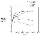
図2は本実施の形態の各サンプルと比較例とを用意して、本発明の効果を確認するための評価試験を行った結果である。(Performance evaluation test)
FIG. 2 showsthe results of an evaluation test for confirming the effect of the present invention by preparing each sample of the present embodiment and a comparative example.
本評価試験において、以下のように本実施の形態の各サンプルあるいは比較例の電気化学キャパシタ200を作製し、以下の充放電条件でサイクル試験を実施する。そして、各サンプルのサイクル回数に対する負極の電位変動の様子を評価する。 In this evaluation test, each sample of the present embodiment or the
サンプル1の電気化学キャパシタ200は以下の構成で作製する。正極2、負極3の集電体2a、3aのサイズを3cm×4cmとする。正極2の分極性電極層2bに含まれる活性炭としてアルカリ賦活活性炭を用いる。負極3の負極電極層3bに含まれる炭素材料として易黒鉛化炭素を用いる。電解液は、溶媒としてECとDMCとの1:1の比率で混合した溶液と、電解質として1mol/リットルのLiPF6と、添加物として溶媒の重量に対して2wt%の量のγ−ブチロラクトンと、を混合する。The
サンプル2の電気化学キャパシタ200は、サンプル1の電気化学キャパシタ200における、γ−ブチロラクトンに代えて、γ−バレロラクトンを溶媒の重量に対して2wt%混合したものを用いる。 The
サンプル3の電気化学キャパシタ200は、サンプル1の電気化学キャパシタにおける、γ−ブチロラクトンに代えて、γ−カプロラクトンを溶媒の重量に対して2wt%混合したものを用いる。 The
比較例の電気化学キャパシタ200として、ラクトンを添加しないことを除いて、サンプル1と同様の構成である電気化学キャパシタ200を用いる。 As the
サイクル試験の条件は、上限電圧4V、下限電圧2.8V、充電条件0.5ACCCV(constant current constant volt)、放電条件0.25ACCCVである。これらは900〜1000Cでの充放電に相当する。The conditions for the cycle test are an upper limit voltage of 4 V, a lower limit voltage of 2.8 V, a charge condition of 0.5 ACCV (constant current constant voltage), and a discharge condition of 0.25 ACCCV. These correspond tocharging and discharging at900 to 1000C .
図2より、比較例に比べて、実施例のサンプル1〜3はサイクル回数増加に伴う負極の電位の電位上昇が抑制されている。 As shown in FIG. 2, compared with the comparative example, the
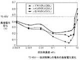
さらに、負極3の炭素材料の外表部分の結晶構造を、X線回折を用いて確認した結果を図3に示す。X線回折では、負極電極層A〜Dを測定する。負極電極層Aは、サンプル1の負極電極層3bである。負極電極層Bは、比較例の負極電極層3bである。負極電極層Cは、DMCとγ−ブチロラクトンを1:1で混合した電解液を含浸した負極電極層3bである。負極電極層Dは、電解液を含浸していない。初期充電を行った状態でこれら負極電極層A〜Cの層間距離を測定し比較する。因みに負極電極層Cは負極電極層A、Bに対して規定の電位まで充電を行うことができない。 Furthermore, the result of having confirmed the crystal structure of the outer surface part of the carbon material of the
図3より、負極電極層Bに比べて負極電極層Aの回折角が小さい。これは、負極電極層3bを構成する炭素材料の層間が拡張されていることを示している。このことから、電解液中に微量のラクトンを添加することにより、ラクトンが、負極電極層3bを構成する炭素材料の結晶構造の層間を拡張することが可能であることがわかる。 From FIG. 3, the diffraction angle of the negative electrode layer A is smaller than that of the negative electrode layer B. This indicates that the carbon material layer constituting the
また、(表1)〜(表3)に、サンプル1〜3の添加剤としてのγ−ブチロラクトン、γ−バレロラクトン、γ−カプロラクトンそれぞれの添加量を変化させた際のキャパシタ特性をそれぞれ示す。図4は、(表1)〜(表3)の結果を一つにまとめたものである。 Tables 1 to 3 show capacitor characteristics when the addition amounts of γ-butyrolactone, γ-valerolactone, and γ-caprolactone as additives of
なお、(表1)〜(表3)のサイクル特性の数値は、サイクル試験後の各セル特性値と初期状態の各セル特性値との比率を百分率として表している。また、(表1)〜(表3)の「ΔE」はサイクル試験前後における負極電位の値の差分を表している。 In addition, the numerical value of the cycle characteristic of (Table 1) to (Table 3) represents the ratio between each cell characteristic value after the cycle test and each cell characteristic value in the initial state as a percentage. Further, “ΔE” in (Table 1) to (Table 3) represents the difference in the value of the negative electrode potential before and after the cycle test.
図4および(表1)〜(表3)より、電気化学キャパシタの電解液への添加物として、γ−ブチロラクトンだけでなく、γ−バレロラクトンやγ−カプロラクトンについても、同様に0.001〜5wt%の範囲において負極の電位変動抑制が顕著である。 From FIG. 4 and (Table 1) to (Table 3), not only γ-butyrolactone but also γ-valerolactone and γ-caprolactone as additives to the electrolytic solution of the electrochemical capacitor are similarly 0.001 to 0.001. In the range of 5 wt%, the potential fluctuation suppression of the negative electrode is significant.
続いて、上記サンプル1〜3の構成に加えてさらにヒドロキシ酪酸を表に示す範囲の量を含有させたものをそれぞれサンプル4〜6として作製し評価する。その結果を(表4)に示す。 Subsequently, in addition to the configurations of
なお、(表4)におけるサンプル4〜6に用いる各ラクトン類の添加量は2.0wt%である。そして、(表4)で示された体積増加量の評価は以下のように行う。評価に用いる電気化学キャパシタは、3mm×4mmの集電体を用いた正極、負極と、上記のラクトン類を含む表4に示される構成の電解液を90mm×90mm四方のラミネートフィルム内に収容して作製される。そして作製した電気化学キャパシタをサイクル試験にかけ、サイクル試験前後におけるラミネートフィルム製の外装体内の体積増加量を測定して評価する。体積増加量は、サイクル試験前後のサンプルの電気化学キャパシタを、水が溜まった水槽中に入れ、あふれ出す水の量の変化を測定することで、評価する。In addition, the addition amount of each lactone used for the samples 4-6 in (Table 4) is 2.0 wt%. Then, the volume increase shown in (Table 4) is evaluated as follows. The electrochemical capacitor used for evaluation contains a positive electrode and a negative electrode using a current collector of 3 mm × 4 mm, and anelectrolytic solution having the structure shown in Table 4 containing the above lactonesin a 90 mm × 90 mm square laminate film. Produced. Then, the produced electrochemical capacitor is subjected to a cycle test, and the volume increase in the laminate film outer package before and after the cycle test is measured and evaluated. The volume increase is evaluated by measuring the change in the amount of overflowing water by placing the electrochemical capacitors of the sample before and after the cycle test into a water tank in which water has accumulated.
(表4)より、ヒドロキシ酪酸を溶媒に対して0.00001wt%以上3wt%以下含有したサンプル4〜6は、ヒドロキシ酪酸類を上記範囲で含有していないサンプル1〜3に比べてセルの体積増加量が小さいことがわかる。このことから、上記範囲においてヒドロキシ酪酸類やヒドロキシ吉草酸類を添加することによって、電気化学キャパシタとして、内部のガス発生を抑制し、信頼性を高めることができる。 From Table 4, samples 4-6 containing hydroxybutyric acid in an amount of 0.00001 wt% or more and 3 wt% or less with respect to the solvent were compared with samples 1-3 containing no hydroxybutyric acid in the above range. It can be seen that the increase is small. Therefore, by adding hydroxybutyric acid or hydroxyvaleric acid within the above range, as an electrochemical capacitor, internal gas generation can be suppressed and reliability can be improved.
なお、炭素材料を構成する材料については、本実施の形態において低抵抗や充放電サイクル寿命の面で優れている易黒鉛化炭素を使用している。しかしながら、他にも、黒鉛質炭素、低温焼成炭素、難黒鉛化炭素などを用いてもよい。例えば、黒鉛質炭素は、高耐圧や充放電サイクルにおけるエネルギー損失が少ない点で優れており、低温焼成炭素は、高容量や低抵抗の面で優れており、難黒鉛化炭素は、高容量やサイクル損失が小さい面で優れている。これらの特性に応じて、適宜材料の選択を行うのが好ましい。 As the material constituting the carbon material, graphitizable carbon that is excellent in terms of low resistance and charge / discharge cycle life is used in the present embodiment. However, in addition, graphitic carbon, low-temperature calcined carbon, non-graphitizable carbon, and the like may be used. For example, graphitic carbon is superior in terms of high breakdown voltage and low energy loss in charge / discharge cycles, low-temperature calcined carbon is superior in terms of high capacity and low resistance, and non-graphitizable carbon is high capacity and Excellent in terms of low cycle loss. It is preferable to select materials as appropriate according to these characteristics.
以上より、本実施の形態の電気化学キャパシタ200は、電解液中に0.001wt%以上5wt%以下のラクトンを含有している。これにより、負極3にラクトンがカチオンと共挿入され、負極3の電極層3b近傍での反応が促進される。これにより、正極2と負極3との間での充放電のバランスが安定する。そのため、急速な充放電中に生じる負極3の電位変化を抑制することができ、エネルギー密度を高めることができる。 As described above, the
本発明にかかる電気化学キャパシタは急速な充放電においても優れたエネルギー密度を示す。よって、例えば、回生やバックアップに用いられるハイブリッド車両電源としての用途が特に有用である。 The electrochemical capacitor according to the present invention exhibits excellent energy density even during rapid charge / discharge. Therefore, for example, the use as a hybrid vehicle power source used for regeneration or backup is particularly useful.
1 キャパシタ素子
2 正極
2a,3a 集電体
2b 分極性電極層
3 負極
3b 負極電極層
4 セパレータ
5a,5b リード線
6 外装ケース
7 封口部材
100 電極巻回ユニット
101 正極
102 負極
103 セパレータ
104,105 リチウム金属
107,108 電極端子
109 管棒DESCRIPTION OF
Claims (4)
Translated fromJapanese前記カチオンを吸蔵する電極層を有する負極と、前記負極と対向する正極と、前記正極と前記負極との間に設けられたセパレータを有し前記電解液が含浸されたキャパシタ素子と、
前記電解液と前記キャパシタ素子とを収容する外装体とを備え、
前記電解液は、前記溶媒に対して0.001wt%以上、5wt%以下のラクトン類と、前記溶媒に対して0.00001wt%以上3wt%以下の、ヒドロキシ酪酸類とヒドロキシ吉草酸類との少なくともいずれか1種類からなる酸と、を含む電気化学キャパシタ。An electrolyte containing a cation, an anion, and a solvent;
A negative electrode having an electrode layer of occluding saidcation, a positive electrode facing the negative electrode, and a capacitor element wherein the electrolytic solution comprises a separator provided between the positive electrode and the negative electrode is impregnated,
An exterior body containing the electrolytic solution and the capacitor element;
The electrolyte includes atleast 0.001 wt% or more and 5 wt% or less of lactonewith respect to the solvent, and at least 0.00001 wt% or more and 3 wt% or less of hydroxybutyric acid and hydroxyvaleric acid with respect to the solvent. An electrochemical capacitor comprisingany one kind of acid .
Applications Claiming Priority (3)
| Application Number | Priority Date | Filing Date | Title |
|---|---|---|---|
| JP2011031582 | 2011-02-17 | ||
| JP2011031582 | 2011-02-17 | ||
| PCT/JP2012/001017WO2012111333A1 (en) | 2011-02-17 | 2012-02-16 | Electrochemical capacitor |
Publications (2)
| Publication Number | Publication Date |
|---|---|
| JPWO2012111333A1 JPWO2012111333A1 (en) | 2014-07-03 |
| JP6010763B2true JP6010763B2 (en) | 2016-10-19 |
Family
ID=46672277
Family Applications (1)
| Application Number | Title | Priority Date | Filing Date |
|---|---|---|---|
| JP2012557843AExpired - Fee RelatedJP6010763B2 (en) | 2011-02-17 | 2012-02-16 | Electrochemical capacitor |
Country Status (4)
| Country | Link |
|---|---|
| US (1) | US9218912B2 (en) |
| JP (1) | JP6010763B2 (en) |
| CN (1) | CN103370758A (en) |
| WO (1) | WO2012111333A1 (en) |
Families Citing this family (5)
| Publication number | Priority date | Publication date | Assignee | Title |
|---|---|---|---|---|
| US20150022951A1 (en)* | 2011-11-11 | 2015-01-22 | Nippon Kodoshi Corporation | Separator for electrolytic capacitor and electrolytic capacitor |
| JP6292833B2 (en)* | 2013-11-19 | 2018-03-14 | 旭化成株式会社 | Non-aqueous lithium storage element |
| CN114730879B (en)* | 2019-11-27 | 2024-04-05 | 株式会社村田制作所 | Secondary battery |
| WO2022181605A1 (en)* | 2021-02-26 | 2022-09-01 | パナソニックIpマネジメント株式会社 | Electrochemical capacitor |
| CN117063258A (en)* | 2021-03-19 | 2023-11-14 | 松下知识产权经营株式会社 | Electrochemical capacitor |
Family Cites Families (7)
| Publication number | Priority date | Publication date | Assignee | Title |
|---|---|---|---|---|
| JP3623113B2 (en) | 1998-12-03 | 2005-02-23 | ルビコン株式会社 | Electrolytic capacitor |
| JP4302366B2 (en)* | 2001-07-10 | 2009-07-22 | 三菱化学株式会社 | Non-aqueous electrolyte and secondary battery using the same |
| JP4156481B2 (en)* | 2003-09-19 | 2008-09-24 | 日東電工株式会社 | Gel electrolyte, its production method and its use |
| JP4732072B2 (en) | 2005-08-30 | 2011-07-27 | 富士重工業株式会社 | Winding type lithium ion capacitor |
| JP4924966B2 (en)* | 2005-10-17 | 2012-04-25 | 富士重工業株式会社 | Lithium ion capacitor |
| JP2008300684A (en)* | 2007-05-31 | 2008-12-11 | Nichicon Corp | Electrolytic solution for driving electrolytic capacitor, and electrolytic capacitor |
| JP5169435B2 (en)* | 2008-02-14 | 2013-03-27 | ソニー株式会社 | Secondary battery and manufacturing method thereof |
- 2012
- 2012-02-16JPJP2012557843Apatent/JP6010763B2/ennot_activeExpired - Fee Related
- 2012-02-16WOPCT/JP2012/001017patent/WO2012111333A1/enactiveApplication Filing
- 2012-02-16CNCN2012800090223Apatent/CN103370758A/enactivePending
- 2013
- 2013-08-02USUS13/957,435patent/US9218912B2/ennot_activeExpired - Fee Related
Also Published As
| Publication number | Publication date |
|---|---|
| JPWO2012111333A1 (en) | 2014-07-03 |
| WO2012111333A1 (en) | 2012-08-23 |
| US9218912B2 (en) | 2015-12-22 |
| US20130314846A1 (en) | 2013-11-28 |
| CN103370758A (en) | 2013-10-23 |
Similar Documents
| Publication | Publication Date | Title |
|---|---|---|
| JP5873971B2 (en) | Electrochemical capacitor and electrode used therefor | |
| JP5392355B2 (en) | Electric double layer capacitor | |
| JP6019400B2 (en) | Electrode for electrochemical capacitor and electrochemical capacitor using the same | |
| JP6010763B2 (en) | Electrochemical capacitor | |
| JP6730284B2 (en) | Electrode manufacturing method and power storage device manufacturing method | |
| JP2012004491A (en) | Power storage device | |
| JP6487841B2 (en) | Power storage device | |
| JP2013089606A (en) | Electrode sheet, method of manufacturing the same and power storage device using the same | |
| JP2008282838A (en) | Hybrid electric double layer capacitor | |
| WO2013146464A1 (en) | Electrode material, and capacitor and secondary battery using said electrode material | |
| CN109559903B (en) | Electrolyte solution for electrochemical device and electrochemical device | |
| JP2012079813A (en) | Manufacturing method of electric storage device | |
| JP2012028366A (en) | Power storage device | |
| JP2009272585A (en) | Electrochemical capacitor | |
| JP2016167476A (en) | Power storage device | |
| JP5810271B2 (en) | Electrochemical capacitor manufacturing method and electrochemical capacitor manufactured using the same | |
| JP6718905B2 (en) | Lithium ion capacitor | |
| WO2010092829A1 (en) | Electrolyte solution and electrochemical capacitor using same | |
| CN104662627B (en) | Electrode for capacitor and capacitor using same | |
| WO2015045347A1 (en) | Lithium ion capacitor | |
| JP2015165535A (en) | Power storage device | |
| JP2009218160A (en) | Secondary battery and its manufacturing method | |
| JP2020009998A (en) | Power storage device | |
| WO2015037486A1 (en) | Electrolyte solution for lithium ion capacitors, and lithium ion capacitor | |
| JPWO2016125770A1 (en) | Electrolyte for lithium ion capacitor and lithium ion capacitor |
Legal Events
| Date | Code | Title | Description |
|---|---|---|---|
| A711 | Notification of change in applicant | Free format text:JAPANESE INTERMEDIATE CODE: A711 Effective date:20141006 | |
| A621 | Written request for application examination | Free format text:JAPANESE INTERMEDIATE CODE: A621 Effective date:20150216 | |
| A131 | Notification of reasons for refusal | Free format text:JAPANESE INTERMEDIATE CODE: A131 Effective date:20160329 | |
| RD01 | Notification of change of attorney | Free format text:JAPANESE INTERMEDIATE CODE: A7421 Effective date:20160518 | |
| A521 | Request for written amendment filed | Free format text:JAPANESE INTERMEDIATE CODE: A523 Effective date:20160525 | |
| TRDD | Decision of grant or rejection written | ||
| A01 | Written decision to grant a patent or to grant a registration (utility model) | Free format text:JAPANESE INTERMEDIATE CODE: A01 Effective date:20160809 | |
| A61 | First payment of annual fees (during grant procedure) | Free format text:JAPANESE INTERMEDIATE CODE: A61 Effective date:20160822 | |
| R151 | Written notification of patent or utility model registration | Ref document number:6010763 Country of ref document:JP Free format text:JAPANESE INTERMEDIATE CODE: R151 | |
| LAPS | Cancellation because of no payment of annual fees |