JP6009559B2 - Work machine and control method thereof - Google Patents
Work machine and control method thereofDownload PDFInfo
- Publication number
- JP6009559B2 JP6009559B2JP2014519935AJP2014519935AJP6009559B2JP 6009559 B2JP6009559 B2JP 6009559B2JP 2014519935 AJP2014519935 AJP 2014519935AJP 2014519935 AJP2014519935 AJP 2014519935AJP 6009559 B2JP6009559 B2JP 6009559B2
- Authority
- JP
- Japan
- Prior art keywords
- capacitor
- disturbance
- voltage
- value
- bus
- Prior art date
- Legal status (The legal status is an assumption and is not a legal conclusion. Google has not performed a legal analysis and makes no representation as to the accuracy of the status listed.)
- Expired - Fee Related
Links
Images


Classifications
- E—FIXED CONSTRUCTIONS
- E02—HYDRAULIC ENGINEERING; FOUNDATIONS; SOIL SHIFTING
- E02F—DREDGING; SOIL-SHIFTING
- E02F9/00—Component parts of dredgers or soil-shifting machines, not restricted to one of the kinds covered by groups E02F3/00 - E02F7/00
- E02F9/20—Drives; Control devices
- E02F9/2058—Electric or electro-mechanical or mechanical control devices of vehicle sub-units
- E02F9/2062—Control of propulsion units
- E02F9/2075—Control of propulsion units of the hybrid type
- B—PERFORMING OPERATIONS; TRANSPORTING
- B60—VEHICLES IN GENERAL
- B60L—PROPULSION OF ELECTRICALLY-PROPELLED VEHICLES; SUPPLYING ELECTRIC POWER FOR AUXILIARY EQUIPMENT OF ELECTRICALLY-PROPELLED VEHICLES; ELECTRODYNAMIC BRAKE SYSTEMS FOR VEHICLES IN GENERAL; MAGNETIC SUSPENSION OR LEVITATION FOR VEHICLES; MONITORING OPERATING VARIABLES OF ELECTRICALLY-PROPELLED VEHICLES; ELECTRIC SAFETY DEVICES FOR ELECTRICALLY-PROPELLED VEHICLES
- B60L50/00—Electric propulsion with power supplied within the vehicle
- B60L50/10—Electric propulsion with power supplied within the vehicle using propulsion power supplied by engine-driven generators, e.g. generators driven by combustion engines
- B60L50/16—Electric propulsion with power supplied within the vehicle using propulsion power supplied by engine-driven generators, e.g. generators driven by combustion engines with provision for separate direct mechanical propulsion
- B—PERFORMING OPERATIONS; TRANSPORTING
- B60—VEHICLES IN GENERAL
- B60L—PROPULSION OF ELECTRICALLY-PROPELLED VEHICLES; SUPPLYING ELECTRIC POWER FOR AUXILIARY EQUIPMENT OF ELECTRICALLY-PROPELLED VEHICLES; ELECTRODYNAMIC BRAKE SYSTEMS FOR VEHICLES IN GENERAL; MAGNETIC SUSPENSION OR LEVITATION FOR VEHICLES; MONITORING OPERATING VARIABLES OF ELECTRICALLY-PROPELLED VEHICLES; ELECTRIC SAFETY DEVICES FOR ELECTRICALLY-PROPELLED VEHICLES
- B60L50/00—Electric propulsion with power supplied within the vehicle
- B60L50/40—Electric propulsion with power supplied within the vehicle using propulsion power supplied by capacitors
- E—FIXED CONSTRUCTIONS
- E02—HYDRAULIC ENGINEERING; FOUNDATIONS; SOIL SHIFTING
- E02F—DREDGING; SOIL-SHIFTING
- E02F9/00—Component parts of dredgers or soil-shifting machines, not restricted to one of the kinds covered by groups E02F3/00 - E02F7/00
- E02F9/20—Drives; Control devices
- E02F9/2058—Electric or electro-mechanical or mechanical control devices of vehicle sub-units
- E02F9/2091—Control of energy storage means for electrical energy, e.g. battery or capacitors
- H—ELECTRICITY
- H02—GENERATION; CONVERSION OR DISTRIBUTION OF ELECTRIC POWER
- H02M—APPARATUS FOR CONVERSION BETWEEN AC AND AC, BETWEEN AC AND DC, OR BETWEEN DC AND DC, AND FOR USE WITH MAINS OR SIMILAR POWER SUPPLY SYSTEMS; CONVERSION OF DC OR AC INPUT POWER INTO SURGE OUTPUT POWER; CONTROL OR REGULATION THEREOF
- H02M3/00—Conversion of DC power input into DC power output
- H02M3/02—Conversion of DC power input into DC power output without intermediate conversion into AC
- H02M3/04—Conversion of DC power input into DC power output without intermediate conversion into AC by static converters
- H02M3/10—Conversion of DC power input into DC power output without intermediate conversion into AC by static converters using discharge tubes with control electrode or semiconductor devices with control electrode
- H02M3/145—Conversion of DC power input into DC power output without intermediate conversion into AC by static converters using discharge tubes with control electrode or semiconductor devices with control electrode using devices of a triode or transistor type requiring continuous application of a control signal
- H02M3/155—Conversion of DC power input into DC power output without intermediate conversion into AC by static converters using discharge tubes with control electrode or semiconductor devices with control electrode using devices of a triode or transistor type requiring continuous application of a control signal using semiconductor devices only
- H02M3/156—Conversion of DC power input into DC power output without intermediate conversion into AC by static converters using discharge tubes with control electrode or semiconductor devices with control electrode using devices of a triode or transistor type requiring continuous application of a control signal using semiconductor devices only with automatic control of output voltage or current, e.g. switching regulators
- H02M3/158—Conversion of DC power input into DC power output without intermediate conversion into AC by static converters using discharge tubes with control electrode or semiconductor devices with control electrode using devices of a triode or transistor type requiring continuous application of a control signal using semiconductor devices only with automatic control of output voltage or current, e.g. switching regulators including plural semiconductor devices as final control devices for a single load
- H02M3/1582—Buck-boost converters
- B—PERFORMING OPERATIONS; TRANSPORTING
- B60—VEHICLES IN GENERAL
- B60L—PROPULSION OF ELECTRICALLY-PROPELLED VEHICLES; SUPPLYING ELECTRIC POWER FOR AUXILIARY EQUIPMENT OF ELECTRICALLY-PROPELLED VEHICLES; ELECTRODYNAMIC BRAKE SYSTEMS FOR VEHICLES IN GENERAL; MAGNETIC SUSPENSION OR LEVITATION FOR VEHICLES; MONITORING OPERATING VARIABLES OF ELECTRICALLY-PROPELLED VEHICLES; ELECTRIC SAFETY DEVICES FOR ELECTRICALLY-PROPELLED VEHICLES
- B60L2200/00—Type of vehicles
- B60L2200/40—Working vehicles
- B60L2200/42—Fork lift trucks
- B—PERFORMING OPERATIONS; TRANSPORTING
- B60—VEHICLES IN GENERAL
- B60L—PROPULSION OF ELECTRICALLY-PROPELLED VEHICLES; SUPPLYING ELECTRIC POWER FOR AUXILIARY EQUIPMENT OF ELECTRICALLY-PROPELLED VEHICLES; ELECTRODYNAMIC BRAKE SYSTEMS FOR VEHICLES IN GENERAL; MAGNETIC SUSPENSION OR LEVITATION FOR VEHICLES; MONITORING OPERATING VARIABLES OF ELECTRICALLY-PROPELLED VEHICLES; ELECTRIC SAFETY DEVICES FOR ELECTRICALLY-PROPELLED VEHICLES
- B60L2210/00—Converter types
- B60L2210/10—DC to DC converters
- B60L2210/12—Buck converters
- B—PERFORMING OPERATIONS; TRANSPORTING
- B60—VEHICLES IN GENERAL
- B60L—PROPULSION OF ELECTRICALLY-PROPELLED VEHICLES; SUPPLYING ELECTRIC POWER FOR AUXILIARY EQUIPMENT OF ELECTRICALLY-PROPELLED VEHICLES; ELECTRODYNAMIC BRAKE SYSTEMS FOR VEHICLES IN GENERAL; MAGNETIC SUSPENSION OR LEVITATION FOR VEHICLES; MONITORING OPERATING VARIABLES OF ELECTRICALLY-PROPELLED VEHICLES; ELECTRIC SAFETY DEVICES FOR ELECTRICALLY-PROPELLED VEHICLES
- B60L2210/00—Converter types
- B60L2210/10—DC to DC converters
- B60L2210/14—Boost converters
- B—PERFORMING OPERATIONS; TRANSPORTING
- B60—VEHICLES IN GENERAL
- B60L—PROPULSION OF ELECTRICALLY-PROPELLED VEHICLES; SUPPLYING ELECTRIC POWER FOR AUXILIARY EQUIPMENT OF ELECTRICALLY-PROPELLED VEHICLES; ELECTRODYNAMIC BRAKE SYSTEMS FOR VEHICLES IN GENERAL; MAGNETIC SUSPENSION OR LEVITATION FOR VEHICLES; MONITORING OPERATING VARIABLES OF ELECTRICALLY-PROPELLED VEHICLES; ELECTRIC SAFETY DEVICES FOR ELECTRICALLY-PROPELLED VEHICLES
- B60L2270/00—Problem solutions or means not otherwise provided for
- B60L2270/10—Emission reduction
- B60L2270/14—Emission reduction of noise
- B60L2270/147—Emission reduction of noise electro magnetic [EMI]
- Y—GENERAL TAGGING OF NEW TECHNOLOGICAL DEVELOPMENTS; GENERAL TAGGING OF CROSS-SECTIONAL TECHNOLOGIES SPANNING OVER SEVERAL SECTIONS OF THE IPC; TECHNICAL SUBJECTS COVERED BY FORMER USPC CROSS-REFERENCE ART COLLECTIONS [XRACs] AND DIGESTS
- Y02—TECHNOLOGIES OR APPLICATIONS FOR MITIGATION OR ADAPTATION AGAINST CLIMATE CHANGE
- Y02T—CLIMATE CHANGE MITIGATION TECHNOLOGIES RELATED TO TRANSPORTATION
- Y02T10/00—Road transport of goods or passengers
- Y02T10/60—Other road transportation technologies with climate change mitigation effect
- Y02T10/70—Energy storage systems for electromobility, e.g. batteries
- Y—GENERAL TAGGING OF NEW TECHNOLOGICAL DEVELOPMENTS; GENERAL TAGGING OF CROSS-SECTIONAL TECHNOLOGIES SPANNING OVER SEVERAL SECTIONS OF THE IPC; TECHNICAL SUBJECTS COVERED BY FORMER USPC CROSS-REFERENCE ART COLLECTIONS [XRACs] AND DIGESTS
- Y02—TECHNOLOGIES OR APPLICATIONS FOR MITIGATION OR ADAPTATION AGAINST CLIMATE CHANGE
- Y02T—CLIMATE CHANGE MITIGATION TECHNOLOGIES RELATED TO TRANSPORTATION
- Y02T10/00—Road transport of goods or passengers
- Y02T10/60—Other road transportation technologies with climate change mitigation effect
- Y02T10/7072—Electromobility specific charging systems or methods for batteries, ultracapacitors, supercapacitors or double-layer capacitors
- Y—GENERAL TAGGING OF NEW TECHNOLOGICAL DEVELOPMENTS; GENERAL TAGGING OF CROSS-SECTIONAL TECHNOLOGIES SPANNING OVER SEVERAL SECTIONS OF THE IPC; TECHNICAL SUBJECTS COVERED BY FORMER USPC CROSS-REFERENCE ART COLLECTIONS [XRACs] AND DIGESTS
- Y02—TECHNOLOGIES OR APPLICATIONS FOR MITIGATION OR ADAPTATION AGAINST CLIMATE CHANGE
- Y02T—CLIMATE CHANGE MITIGATION TECHNOLOGIES RELATED TO TRANSPORTATION
- Y02T10/00—Road transport of goods or passengers
- Y02T10/60—Other road transportation technologies with climate change mitigation effect
- Y02T10/72—Electric energy management in electromobility
Landscapes
- Engineering & Computer Science (AREA)
- Power Engineering (AREA)
- Mining & Mineral Resources (AREA)
- Civil Engineering (AREA)
- General Engineering & Computer Science (AREA)
- Structural Engineering (AREA)
- Transportation (AREA)
- Mechanical Engineering (AREA)
- Dc-Dc Converters (AREA)
- Operation Control Of Excavators (AREA)
- Inverter Devices (AREA)
Description
Translated fromJapanese本発明は、蓄電装置の充放電を制御する作業機械及びその制御方法に関する。 The present invention relates to a work machine that controls charging / discharging of a power storage device and a control method thereof.
ハイブリッド型ショベル等のハイブリッド型作業機械には、電気負荷を駆動するための電源装置として、蓄電装置が設けられる。蓄電装置は、電力を蓄積しておくための蓄電部と昇降圧コンバータとを含んでいる。昇降圧コンバータは、蓄電部からの電力を電気負荷に供給し、あるいは発電機等の電気負荷からの電力を蓄電部に供給するためのDCバスの電圧(DCバス電圧)を制御する。 A hybrid work machine such as a hybrid excavator is provided with a power storage device as a power supply device for driving an electric load. The power storage device includes a power storage unit for storing electric power and a buck-boost converter. The step-up / step-down converter controls the voltage of the DC bus (DC bus voltage) for supplying the electric power from the power storage unit to the electric load or supplying the electric power from the electric load such as a generator to the power storage unit.
DCバスを流れる電流量は外乱の影響を受ける。外乱とは、例えば、電気負荷の影響でDCバス電圧が変動することである。外乱があるとDCバス電圧が変動し、したがってDCバスを流れる電流量が変動する。通常、DCバス電圧が目標電圧となるように制御が行なわれ、電流がDCバスから電気負荷に流れるように、或いは、電気負荷(発電機)の発電による電流がDCバスを介して蓄電部に流れるように制御する。 The amount of current flowing through the DC bus is affected by disturbance. The disturbance is, for example, that the DC bus voltage fluctuates due to the influence of an electric load. When there is a disturbance, the DC bus voltage fluctuates, and therefore the amount of current flowing through the DC bus fluctuates. Normally, control is performed so that the DC bus voltage becomes the target voltage, so that the current flows from the DC bus to the electric load, or the current generated by the electric load (generator) is supplied to the power storage unit via the DC bus. Control to flow.
外乱はDCバス電圧に対してノイズとして作用するので、外乱の影響を除去することが望ましい。ここで、ハイブリッド型ショベルの電気系におけるノイズの影響によるCPUの誤動を防止する技術が提案されている(例えば、特許文献1参照)。 Since the disturbance acts as noise on the DC bus voltage, it is desirable to remove the influence of the disturbance. Here, a technique for preventing a malfunction of the CPU due to the influence of noise in the electric system of the hybrid excavator has been proposed (see, for example, Patent Document 1).
ショベル、ホイルローダ等の作業機械は、前後進だけでなく種々の作業を実行できるように構成されている。したがって、そのサイズの増大は、周辺物体との接触を回避するための様々な制限が加わることから、作業性の低下をもたらし得る。特に、ショベル等の旋回機能を備える作業機械における旋回体のサイズの増大は、作業性の著しい低下をもたらし得る。 Work machines such as excavators and wheel loaders are configured so as to be able to perform not only forward and backward movement but also various work. Therefore, the increase in the size may lead to a decrease in workability because various restrictions are added to avoid contact with surrounding objects. In particular, an increase in the size of the swivel body in a work machine having a swivel function such as a shovel can lead to a significant decrease in workability.
その一方、蓄電装置、DCバス等の電気機器は、ハイブリッド型の作業機械を実現するために近年新たに追加された機器であり、従来の油圧駆動型の作業機械には搭載されてない。 On the other hand, electrical devices such as a power storage device and a DC bus are devices newly added in recent years in order to realize a hybrid type work machine, and are not mounted on a conventional hydraulically driven work machine.
そのため、新たに追加される機器のサイズは、できるだけ小さいものであることが望ましく、DCバスを構成するコンデンサのサイズもできるだけ小さいものであることが望ましい。 Therefore, the size of the newly added device is desirably as small as possible, and the size of the capacitor constituting the DC bus is desirably as small as possible.
しかしながら、コンデンサのサイズを小さくすると、そのコンデンサの容量も小さくなるため、DCバスの電圧が変動し易くなる。この場合、昇降圧コンバータの制御性が悪ければ、DCバスの電圧値が上限値を超えてしまい、電圧異常を引き起こし、ひいては、作業の中断や遅延を引き起こすおそれがある。 However, if the size of the capacitor is reduced, the capacitance of the capacitor is also reduced, and the voltage of the DC bus is likely to fluctuate. In this case, if the controllability of the step-up / step-down converter is poor, the voltage value of the DC bus exceeds the upper limit value, causing a voltage abnormality, which may result in interruption or delay of work.
本発明は上述の問題点に鑑みなされたものであり、昇降圧コンバータの制御性を高めることのできる作業機械及びその制御方法を提供することを目的とする。 The present invention has been made in view of the above-described problems, and an object thereof is to provide a work machine capable of improving the controllability of a buck-boost converter and a control method thereof.
本発明の一実施態様によれば、蓄電器の充放電電圧を制御して、電動機へ電力を供給する作業機械であって、前記蓄電器を充放電制御する電圧変換回路と、前記電圧変換回路の制御ループに組み込まれた外乱推定器とを有し、前記外乱推定器は、外乱の影響を受ける電流量を外乱補正指令値として算出し、該外乱補正指令値を前記制御ループに対して与えることを特徴とする作業機械が提供される。 According to one embodiment of the present invention, there is provided a working machine that controls a charge / discharge voltage of a capacitor and supplies electric power to an electric motor, the voltage conversion circuit that controls charge / discharge of the capacitor, and the control of the voltage conversion circuit A disturbance estimator incorporated in a loop, wherein the disturbance estimator calculates a current amount affected by the disturbance as a disturbance correction command value, and gives the disturbance correction command value to the control loop. A featured work machine is provided.
また、本発明の一実施態様によれば、蓄電器の充放電電圧を制御して、電動機へ電力を供給する作業機械の制御方法であって、電圧変換回路が前記蓄電器を充放電制御するステップと、前記電圧変換回路の制御ループに組み込まれた外乱推定器が、外乱の影響を受ける電流量を外乱補正指令値として算出し、該外乱補正指令値を前記制御ループに対して与えるステップとを有する、作業機械の制御方法が提供される。 Further, according to one embodiment of the present invention, there is provided a control method for a work machine that controls a charge / discharge voltage of a capacitor and supplies electric power to an electric motor, wherein the voltage conversion circuit performs charge / discharge control of the capacitor; A disturbance estimator incorporated in the control loop of the voltage conversion circuit calculates a current amount affected by the disturbance as a disturbance correction command value, and gives the disturbance correction command value to the control loop. A method for controlling a work machine is provided.
本発明によれば、外乱推定器で算出した外乱成分に基づいて生成した外乱補正指令値を昇降圧コンバータの電圧指令値に与えて、昇降圧コンバータへの外乱の影響を排除し、昇降圧コンバータの制御性を高めることができる。 According to the present invention, the disturbance correction command value generated based on the disturbance component calculated by the disturbance estimator is given to the voltage command value of the buck-boost converter to eliminate the influence of the disturbance on the buck-boost converter, and the buck-boost converter Controllability can be improved.
次に、実施形態について図面を参照しながら説明する。 Next, embodiments will be described with reference to the drawings.
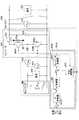
図1は本発明の第1実施形態による充放電制御装置のブロック図である。充放電制御装置200は、蓄電器としてのキャパシタ400からDCバス500に流れる電流を制御してDCバス500の電圧を制御する装置である。 FIG. 1 is a block diagram of a charge / discharge control apparatus according to a first embodiment of the present invention. The charge /
充放電制御装置200は、昇降圧コンバータ300(以下、コンバータ300と称する。)と、コンバータ300に与える操作指令を生成する操作指令生成部600とを有する。 Charge /
コンバータ300は、キャパシタ400の充放電電圧を電圧変換する電圧変換回路である。コンバータ300は、DC電圧を変換するためのスイッチング回路であり、スイッチング素子である昇圧用IGBT302A及び降圧用IGBT302Bを有している。昇圧用IGBT302Aと降圧用IGBT302Bとの間にリアクトル301の一端が接続され、リアクトル301の他端は蓄電器であるキャパシタ400の電極に接続される。リアクトル301は、昇圧用IGBT302Aのオン/オフに伴って生じる誘導起電力をDCバス500に供給するために設けられている。
昇圧用IGBT302A及び降圧用IGBT302Bは、例えば、MOSFET(Metal Oxide Semiconductor Field Effect Transistor)をゲート部に組み込んだバイポーラトランジスタで構成され、大電力の高速スイッチングが可能な半導体素子(スイッチング素子)である。昇圧用IGBT302A及び降圧用IGBT302Bは、操作指令生成部600により、ゲート端子にPWM電圧が印加されることによって駆動される。昇圧用IGBT302A及び降圧用IGBT302Bには、整流素子であるダイオード302a及び302bがそれぞれ並列接続される。なお、コンバータ300が生成する電流iは電流計303により検出される。 The step-
コンバータ300の出力端子はDCバス500の入力端子に接続され、コンバータ300で生成した電流iがDCバス500に流れる。これにより、DCバス500に電圧(DCバス電圧)が発生する。DCバス500にはDCバス電圧VDCを検出する電圧計510が設けられている。DCバス500には電動モータ(電動機)等の負荷が接続されており、DCバス500から供給される電流により負荷は駆動される。コンバータ300は、DCバス500の電圧が一定電圧になるようにキャパシタ400を充放電制御する。図1ではDCバス500に接続される電動モータ等を負荷520として表している。そして、負荷520としての電動モータの力行時にDCバス500から電動モータに供給される電力、電動モータの回生時に電動モータからDCバス500へ供給される電力等が、コンバータ300による充放電制御に対する外乱となる。The output terminal of
キャパシタ400は、起電力(電圧)Vと、内部抵抗Rcapと、静電容量Ccapとを有している。また、キャパシタ400の端子間に電圧計410が接続され、キャパシタ電圧Vcapを電圧計410により検出することができる。 The
キャパシタ400は多数のキャパシタセルが接続されて構成されており、各セル群の電圧を均等化するための均等化回路がキャパシタ400の内部に設けられている。この均等化回路が行なう均等化制御は、キャパシタ400にとって負荷となる。キャパシタ400に対する負荷は、均等化制御のみではなく他の要因による負荷がある。なお、図1では、キャパシタ400に対する負荷を、キャパシタ400の電極間に接続された負荷420として表している。 The
ここで、コンバータ300の出力端子である正極端子と負極端子との間に、平滑用のコンデンサ304が接続される。コンデンサ304は、DCバス電圧を平滑化するための蓄電素子である。この平滑用コンデンサ304によって、DCバス500の電圧は予め定められた電圧に維持される。 Here, a
このように、充放電制御装置200は、DCバス500に蓄電部としてのコンデンサ304を備えることで、負荷520の回生時に負荷520からDCバス500へ電力が供給されても、DCバス500の電圧を平滑化することができる。その結果、DCバス500の電圧上昇を抑制することができる。 As described above, the charge /
ところが、コンデンサ304を小型化するとその容量が小さくなってしまう。この場合、充放電制御装置200は、負荷520の回生時に負荷520からDCバス500へ供給される電力の影響を受け易くなる。つまり、負荷520が外乱となってしまい、負荷520の状態に応じてDCバス500の電圧が変動してしまう。このため、本実施形態では、充放電制御装置200に操作指令生成部600を設け、外乱の影響を低減できるようにする。 However, when the
操作指令生成部600は、コンバータ300に操作指令を供給してコンバータ300を駆動させるために設けられる。具体的には、操作指令生成部600が出力する操作指令は、昇圧用IGBT302A及び降圧用IGBT302Bのゲート端子に印加するPWM電圧である。このPWM電圧がゲート端子に印加されることで、昇圧用IGBT302A及び降圧用IGBT302Bは駆動され、電流iが流れる。 The operation
操作指令生成部600は、PI制御器610とコンバータ制御器620とを含む。PI制御器610は、入力された目標DCバス電圧に基づいて一次操作指令を生成し、コンバータ制御器620に供給する。一次操作指令はコンバータ300に印加するDC電圧のデューティを表す指令値である。 Operation
コンバータ制御器620は、PI制御器610から供給される一次操作指令(デューティ指令)に基づいて最終的な操作指令を生成し、コンバータ300に供給する。コンバータ300は操作指令に基づいてキャパシタ電流iを生成し、DCバス500に供給する。これによりDCバス500のDCバス電圧VDCが発生する。このDCバス電圧VDCはPI制御器610に入力される目標DCバス電圧VDCTにフィードバックされる。すなわち、目標DCバス電圧VDCTから、DCバス500で検出されたDCバス電圧VDCが減算され、これがPI制御器610に入力される。
以上のように、目標DCバス電圧VDCTが、PI制御器610からコンバータ制御器620を通って操作指令とてしてコンバータ300に供給され、DCバス500のDCバス電圧VDCが目標DCバス電圧VDCTに戻るという制御ループが形成されている。As described above, the target DC bus voltage VDCT is supplied as an operation command from the
本実施形態では、以上の構成に対して外乱補償器630が付加される。外乱補償器630は、PI制御器610から出力される一次操作指令を補正するための外乱補正指令値を生成し出力する。外乱補正指令値は、DCバス電圧VDCを生成する際に外乱の影響による電圧を補正するための指令値であり、PI制御器610から出力される一次操作指令に加算されることで、一次操作指令が補正される。この補正された一次操作指令がコンバータ制御器620に入力される。In the present embodiment, a
外乱補償器630は、外乱の影響による電流変化を推定演算により求める。外乱の影響とは、キャパシタ400に対する負荷420に起因したキャパシタ電流iの変化と、DCバス500に対する負荷520に起因したキャパシタ電流iの変化を含んでいる。外乱補償器630で行なわれる推定演算について以下に説明する。なお、外乱補償器630は、外乱の推定演算を行なう外乱推定器に相当する。 The
まず、キャパシタ400が放電する際(DCバス電圧VDCを昇圧する際)の、外乱の推定演算について説明する。First, the disturbance estimation calculation when the
コンバータ300の出力電圧を昇圧する際に、昇圧用IGBT302Aの一回のスイッチングで変化する電流iの増分は、以下の式(1)で求められる。 When boosting the output voltage of the

DCバス電圧VDCの外乱成分(振動成分)をAとすると、電圧計510で検出したDCバス電圧VDCは、VDC=VDCR+Aである。VDCRはDCバス電圧の目標電圧値であり、理想電圧値である。また、キャパシタ電圧Vcapの外乱成分(振動成分)をBとすると、電圧計410で検出したキャパシタ電圧Vcapは、Vcap=Vcapi+Bである。Vcapiは、電流iが流れたときの理想電圧値である。When the disturbance component of the DC bus voltageV DC (vibration component) and A, the DC bus voltageV DC detected by the voltmeter510, aV DC= VDCR + A. VDCR is a target voltage value of the DC bus voltage and is an ideal voltage value. When the disturbance component (vibration component) of the capacitor voltage Vcap is B, the capacitor voltage Vcap detected by the
したがって、式(1)は以下のように式(2)で表される。 Therefore, Formula (1) is represented by Formula (2) as follows.
キャパシタ400を充電する際(DCバス電圧VDCを降圧する際)の、外乱の推定演算は、上述の推定演算と同様に以下の式(4)〜(6)により行なうことができる。The disturbance estimation calculation when charging the capacitor 400 (when the DC bus voltageVDC is stepped down) can be performed by the following formulas (4) to (6), similarly to the above-described estimation calculation.
コンバータ300の出力電圧を降圧する際に、降圧用IGBT302Bの一回のスイッチングで変化する電流iの減分は、以下の式(4)で求められる。 When the output voltage of the
以上のように、外乱補償器630は、キャパシタ電圧Vcapと、DCバス電圧VDCと一次操作指令とから、外乱補正指令値を推定演算により算出する。したがって、外乱補償器630は、キャパシタ電流iに対する外乱を推定演算で求めているのであり、いわゆる外乱オブザーバとして機能する。As described above, the
以上のように算出した、外乱補正指令値により一次操作指令を補正することで、予め外乱を考慮した補正後の一次操作指令を生成する。すなわち、キャパシタ電圧VcapとDCバス電圧VDCの外乱成分とから、キャパシタ電流iの発振を抑えるような外乱補正指令値を算出し、これを一次操作指令に加えて補正後の一次操作指令とする。したがって、外乱による制御発振(電流iの発振)が抑制されるため、コンバータ300の制御性が向上する。また、制御における異常の発生が防止される。さらに、コンバータ300に対して過大な負荷がかからないので、コンバータ300の劣化が抑制され、寿命を縮めることが無くなる。By correcting the primary operation command with the disturbance correction command value calculated as described above, a corrected primary operation command in consideration of the disturbance is generated in advance. That is, a disturbance correction command value that suppresses the oscillation of the capacitor current i is calculated from the disturbance component of the capacitor voltage Vcap and the DC bus voltage VDC , and this is added to the primary operation command as a corrected primary operation command. . Therefore, since control oscillation (oscillation of current i) due to disturbance is suppressed, the controllability of
また、外乱補償器630により算出した外乱補正指令値を一次操作指令に加えるだけの制御によって外乱の影響を抑制するので、既存のフィードバック制御におけるフィードバックループを変更する必要がなく、複雑な制御を行なわずに外乱による影響を除去することができる。 Further, since the influence of the disturbance is suppressed by controlling the disturbance correction command value calculated by the
図2は、外乱オブザーバによる効果を説明する図である。具体的には、図2上段が外乱の一例としての負荷520(電動モータ)の出力の時間的推移を示し、図2中段がDCバス電圧VDCの時間的推移を示し、図2下段がキャパシタ電流iの時間的推移を示す。また、実線で示す推移は、外乱オブザーバとしての外乱補償器630を用いた場合の推移を示し、点線で示す推移は、外乱補償器630を用いない場合の推移を示す。FIG. 2 is a diagram for explaining the effect of the disturbance observer. Specifically, the upper part of FIG. 2 shows the temporal transition of the output of the load 520 (electric motor) as an example of the disturbance, the middle part of FIG. 2 shows the temporal transition of the DC bus voltageVDC , and the lower part of FIG. The time transition of the current i is shown. A transition indicated by a solid line indicates a transition when the
図2に示すように、外乱補償器630を用いた場合には、電動モータの出力(回生電力)がステップ状に増加したときのキャパシタ電流の立ち上がりは、外乱補償器630を用いない場合のキャパシタ電流の立ち上がりよりも速い。なお、ここでは、キャパシタ電流は、DCバス500からキャパシタ400に流れる電流である。その結果、外乱補償器630を用いた場合のDCバス電圧の変動は、外乱補償器630を用いない場合に比べて小さく、外乱補償器630を用いない場合のように上限値を超えることはない。また、外乱補償器630を用いた場合のDCバス電圧の変動は、外乱補償器630を用いない場合に比べて、変動が生じた後の目標DCバス電圧への復帰も早い。 As shown in FIG. 2, when the
以上の構成により、外乱補償器630は、コンバータ300への外乱の影響を抑制或いは排除することによって、コンバータ300の制御性を向上させることができる。 With the above configuration, the
次に、本発明の第2実施形態による充放電制御装置200Aについて説明する。 Next, a charge / discharge control apparatus 200A according to a second embodiment of the present invention will be described.
上述の第1実施形態における操作指令生成部600では、入力された目標DCバス電圧VDCTに基づいてPI制御器610が一次操作指令を生成し、これを外乱補償器630からの外乱補正指令値で補正して、コンバータ制御器620に供給する。すなわち、目標DCバス電圧VDCTが、PI制御器610からコンバータ制御器620を通って操作指令(電圧値)とてしてコンバータ300に供給され、DCバス500のDCバス電圧VDCが目標DCバス電圧VDCTにフィードバックされるという制御ループ(電圧ループと称する)が形成されている。In the operation
本発明の第2実施形態では、目標DCバス電圧VDCTから一次操作指令(電流指令)を生成し、この電流指令をキャパシタ電流Icapで補正し、補正後の電流指令から二次操作指令(電圧値)を生成し、この二次操作指令をさらに外乱補償値で補正してからコンバータ制御器620に供給する。In the second embodiment of the present invention, a primary operation command (current command) is generated from the target DC bus voltage VDCT , the current command is corrected with the capacitor current Icap, and the secondary operation command (voltage) is corrected from the corrected current command. Value) is generated, and this secondary operation command is further corrected with a disturbance compensation value, and then supplied to the
図3は本発明の第2実施形態による充放電制御装置200Aのブロック図である。図3において、図1に示す構成部品と同等な部品には同じ符号を付し、その説明は省略する。充放電制御装置200Aは、上述の充放電制御装置200と同様に、蓄電器としてのキャパシタ400からDCバス500に流れる電流を制御してDCバス500の電圧を制御する装置である。 FIG. 3 is a block diagram of a charge / discharge control apparatus 200A according to the second embodiment of the present invention. 3, parts that are the same as the parts shown in FIG. 1 are given the same reference numerals, and descriptions thereof will be omitted. Similarly to the above-described charge /
本実施形態では、キャパシタ400からコンバータ300に流れる電流(キャパシタ電流Icap)を検出する電流計430が、キャパシタ400とコンバータ300のリアクトル301との間に設けられる。後述のように、電流計430で検出したキャパシタ電流Icapにより電流指令を補正する。 In the present embodiment, an ammeter 430 that detects a current (capacitor current Icap) flowing from the
本実施形態による操作指令生成部600Aは、コンバータ300に操作指令を供給してコンバータ300を駆動させるために設けられる。具体的には、操作指令生成部600Aが出力する操作指令は、昇圧用IGBT302A及び降圧用IGBT302Bのゲート端子に印加するPWM電圧である。このPWM電圧がゲート端子に印加されることで、昇圧用IGBT302A及び降圧用IGBT302Bは駆動され、電流iが流れる。 The operation
操作指令生成部600Aは、PI制御器610Aと、コンバータ制御器620と、外乱補償器630と、制御器640とを含む。PI制御器610Aは、入力された目標DCバス電圧に基づいて電流指令を生成し出力する。PI制御器610Aから出力された電流指令から、電流計430で検出したキャパシタ電流Icapが減算され、電流補正が行なわれる。電流補正が行なわれた電流指令は、制御器640に供給される。制御器640は、電流補正された電流指令から二次操作指令を生成し出力する。 Operation
本実施形態では、制御器640から出力された二次操作指令に対して、外乱補償器630からの外乱補償値が加算されることで、二次操作指令が補正される。この補正された二次操作指令がコンバータ制御器620に入力される。 In the present embodiment, the secondary operation command is corrected by adding the disturbance compensation value from the
以上のように、本実施形態では、第1実施形態における制御ループ(電圧ループ)に対して、電流計430で検出したキャパシタ電流Icapを電流指令にフィードバックする制御ループ(電流ループ)が加えられたものである。 As described above, in this embodiment, a control loop (current loop) for feeding back the capacitor current Icap detected by the ammeter 430 to the current command is added to the control loop (voltage loop) in the first embodiment. Is.
上述の第1及び第2実施形態による充放電制御装置200、200Aは、例えばショベルの蓄電装置に適用することができる。 The charge /
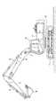
図4は本発明による充放電制御装置が適用可能なショベルの一例であるハイブリッド型ショベルの側面図である。 FIG. 4 is a side view of a hybrid excavator as an example of an excavator to which the charge / discharge control device according to the present invention can be applied.
図4に示すハイブリッド型ショベルの下部走行体1には、旋回機構2を介して上部旋回体3が搭載されている。上部旋回体3には、ブーム4が取り付けられている。ブーム4の先端に、アーム5が取り付けられ、アーム5の先端にバケット6が取り付けられている。ブーム4、アーム5及びバケット6は、ブームシリンダ7、アームシリンダ8、及びバケットシリンダ9によりそれぞれ油圧駆動される。上部旋回体3には、キャビン10が設けられ、且つエンジン等の動力源が搭載される。 An upper swing body 3 is mounted on the
図5は、図4に示すハイブリッド型ショベルの駆動系の構成を示すブロック図である。図5において、機械的動力系は二重線、高圧油圧ラインは太実線、パイロットラインは破線、電気駆動・制御系は細実線でそれぞれ示されている。 FIG. 5 is a block diagram showing the configuration of the drive system of the hybrid excavator shown in FIG. In FIG. 5, the mechanical power system is indicated by a double line, the high pressure hydraulic line is indicated by a thick solid line, the pilot line is indicated by a broken line, and the electric drive / control system is indicated by a thin solid line.
機械式駆動部としてのエンジン11と、アシスト駆動部としての電動発電機12は、変速機13の2つの入力軸にそれぞれ接続されている。変速機13の出力軸には、油圧ポンプとしてメインポンプ14及びパイロットポンプ15が接続されている。メインポンプ14には、高圧油圧ライン16を介してコントロールバルブ17が接続されている。 An
コントロールバルブ17は、ハイブリッド型ショベルにおける油圧系の制御を行う制御装置である。下部走行体1用の油圧モータ1A(右用)及び1B(左用)、ブームシリンダ7、アームシリンダ8、及びバケットシリンダ9は、高圧油圧ラインを介してコントロールバルブ17に接続される。 The
電動発電機12には、インバータ18Aを介して、蓄電器を含む蓄電系120が接続される。また、パイロットポンプ15には、パイロットライン25を介して操作装置26が接続される。操作装置26は、レバー26A、レバー26B、ペダル26Cを含む。レバー26A、レバー26B、及びペダル26Cは、油圧ライン27及び28を介して、コントロールバルブ17及び圧力センサ29にそれぞれ接続される。圧力センサ29は、電気系の駆動制御を行うコントローラ30に接続されている。 The
図4に示すハイブリッド型ショベルには、旋回機構2を電動にした電動式旋回装置が搭載されている。すなわち、旋回機構2を駆動するために旋回用電動機21が設けられている。電動作業要素としての旋回用電動機21は、インバータ20を介して蓄電系120に接続されている。旋回用電動機21の回転軸21Aには、レゾルバ22、メカニカルブレーキ23、及び旋回変速機24が接続される。旋回用電動機21と、インバータ20と、レゾルバ22と、メカニカルブレーキ23と、旋回変速機24とで負荷駆動系が構成される。また、旋回機構2と、旋回機構2を駆動するための旋回用電動機21と、旋回用電動機21に電力を供給するインバータ20と、インバータの駆動を制御するコントローラ30とで、電動式旋回装置が構成される。 The hybrid excavator shown in FIG. 4 is equipped with an electric turning device that makes the turning mechanism 2 electric. That is, a turning
コントローラ30は、ハイブリッド型ショベルの駆動制御を行う主制御部としての制御装置である。コントローラ30は、CPU(Central Processing Unit)及び内部メモリを含む演算処理装置で構成され、CPUが内部メモリに格納された駆動制御用のプログラムを実行することにより実現される装置である。 The
コントローラ30は、圧力センサ29から供給される信号を速度指令に変換し、旋回用電動機21の駆動制御を行う。圧力センサ29から供給される信号は、旋回機構2を旋回させるために操作装置26を操作した場合の操作量を表す信号に相当する。 The
コントローラ30は、電動発電機12の運転制御(電動(アシスト)運転又は発電運転の切り替え)を行うとともに、昇降圧制御部としての昇降圧コンバータ100(図6参照)を駆動制御することによるキャパシタ19の充放電制御を行う。コントローラ30は、キャパシタ19の充電状態、電動発電機12の運転状態(電動(アシスト)運転又は発電運転)、及び旋回用電動機21の運転状態(力行運転又は回生運転)に基づいて、昇降圧コンバータ100の昇圧動作と降圧動作の切替制御を行い、これによりキャパシタ19の充放電制御を行う。また、コントローラ30は、蓄電器電圧検出部によって検出される蓄電器電圧値に基づいて、蓄電器(キャパシタ)の充電率SOCを算出する。 The
図6は、蓄電系120の回路図である。蓄電系120は、蓄電器としてのキャパシタ19と、昇降圧コンバータ100とDCバス110とを含む。DCバス110は、キャパシタ19、電動発電機12、及び旋回用電動機21の間での電力の授受を制御する。キャパシタ19には、キャパシタ電圧値を検出するためのキャパシタ電圧検出部112と、キャパシタ電流値を検出するためのキャパシタ電流検出部113が設けられている。キャパシタ電圧検出部112とキャパシタ電流検出部113によって検出されるキャパシタ電圧値とキャパシタ電流値は、コントローラ30に供給される。 FIG. 6 is a circuit diagram of the
昇降圧コンバータ100は、電動発電機12、及び旋回用電動機21の運転状態に応じて、DCバス電圧値を一定の範囲内に収まるように昇圧動作と降圧動作を切り替える制御を行う。DCバス110は、インバータ18A、及び20と昇降圧コンバータ100との間に配設されており、キャパシタ19、電動発電機12、及び旋回用電動機21の間での電力の授受を行う。 The step-up / step-down
昇降圧コンバータ100の昇圧動作と降圧動作の切替制御は、DCバス電圧検出部111によって検出されるDCバス電圧値、キャパシタ電圧検出部112によって検出されるキャパシタ電圧値、及びキャパシタ電流検出部113によって検出されるキャパシタ電流値に基づいて行われる。 Switching control between the step-up / step-down operation of the buck-
以上のような構成において、アシストモータである電動発電機12が発電した電力は、インバータ18Aを介して蓄電系120のDCバス110に供給され、昇降圧コンバータ100を介してキャパシタ19に供給される。旋回用電動機21が回生運転して生成した回生電力は、インバータ20を介して蓄電系120のDCバス110に供給され、昇降圧コンバータ100を介してキャパシタ19に供給される。 In the configuration as described above, the electric power generated by the
昇降圧コンバータ100は、リアクトル101、昇圧用IGBT(Insulated Gate Bipolar Transistor)102A、降圧用IGBT102B、キャパシタ19を接続するための電源接続端子104、及び、インバータ18A、20を接続するための出力端子106を備える。昇降圧コンバータ100の出力端子106とインバータ18A、20との間は、DCバス110によって接続される。 The step-up / down
リアクトル101の一端は昇圧用IGBT102A及び降圧用IGBT102Bの中間点に接続され、他端は電源接続端子104に接続される。リアクトル101は、昇圧用IGBT102Aのオン/オフに伴って生じる誘導起電力をDCバス110に供給するために設けられている。 One end of the
昇圧用IGBT102A及び降圧用IGBT102Bは、MOSFET(Metal Oxide Semiconductor Field Effect Transistor)をゲート部に組み込んだバイポーラトランジスタで構成され、大電力の高速スイッチングが可能な半導体素子(スイッチング素子)である。昇圧用IGBT102A及び降圧用IGBT102Bは、コントローラ30により、ゲート端子にPWM電圧が印加されることによって駆動される。昇圧用IGBT102A及び降圧用IGBT102Bには、整流素子であるダイオード102a及び102bが並列接続される。 The step-up
キャパシタ19は、昇降圧コンバータ100を介してDCバス110との間で電力の授受が行えるように、充放電可能な蓄電器であればよい。なお、図6には、蓄電器としてキャパシタ19を示すが、キャパシタ19の代わりに、リチウムイオン電池等の充放電可能な二次電池、リチウムイオンキャパシタ、又は、電力の授受が可能なその他の形態の電源を用いてもよい。
電源接続端子104及び出力端子106は、キャパシタ19及びインバータ18A,20が接続可能な端子であればよい。一対の電源接続端子104の間には、キャパシタ電圧を検出するキャパシタ電圧検出部112が接続される。一対の出力端子106の間には、DCバス電圧を検出するDCバス電圧検出部111が接続される。 The
キャパシタ電圧検出部112は、キャパシタ19の電圧値Vcapを検出する。DCバス電圧検出部111は、DCバス110の電圧値VDCを検出する。平滑用のコンデンサ107は、出力端子106の正極端子と負極端子との間に挿入され、DCバス電圧を平滑化するための蓄電素子である。この平滑用のコンデンサ107によって、DCバス110の電圧は予め定められた電圧に維持されている。The
キャパシタ電流検出部113は、キャパシタ19の正極端子(P端子)側においてキャパシタ19に流れる電流の値を検出する検出手段であり、電流検出用の抵抗器を含む。すなわち、キャパシタ電流検出部113は、キャパシタ19の正極端子に流れる電流値I1を検出する。一方、キャパシタ電流検出部116は、キャパシタの負極端子(N端子)側においてキャパシタ19に流れる電流の値を検出する検出手段であり、電流検出用の抵抗器を含む。すなわち、キャパシタ電流検出部116は、キャパシタ19の負極端子に流れる電流値I2を検出する。 The capacitor
昇降圧コンバータ100において、DCバス110を昇圧する際には、昇圧用IGBT102Aのゲート端子にPWM電圧が印加され、降圧用IGBT102Bに並列に接続されたダイオード102bを介して、昇圧用IGBT102Aのオン/オフに伴ってリアクトル101に発生する誘導起電力がDCバス110に供給される。これにより、DCバス110が昇圧される。 In the buck-
DCバス110を降圧する際には、降圧用IGBT102Bのゲート端子にPWM電圧が印加され、降圧用IGBT102B、インバータ18A、20を介して供給される回生電力がDCバス110からキャパシタ19に供給される。これにより、DCバス110に蓄積された電力がキャパシタ19に充電され、DCバス110が降圧される。 When the
本実施形態では、キャパシタ19の正極端子を昇降圧コンバータ100の電源接続端子104に接続する電源ライン114に、当該電源ライン114を遮断することのできる遮断器としてリレー130−1が設けられる。リレー130−1は、電源ライン114へのキャパシタ電圧検出部112の接続点115とキャパシタ19の正極端子の間に配置されている。リレー130−1はコントローラ30からの信号により作動し、キャパシタ19からの電源ライン114を遮断することで、キャパシタ19を昇降圧コンバータ100から切り離すことができる。 In the present embodiment, a relay 130-1 is provided as a circuit breaker capable of interrupting the
また、キャパシタ19の負極端子を昇降圧コンバータ100の電源接続端子104に接続する電源ライン117に、当該電源ライン117を遮断することのできる遮断器としてリレー130−2が設けられる。リレー130−2は、電源ライン117へのキャパシタ電圧検出部112の接続点118とキャパシタ19の負極端子の間に配置されている。リレー130−2はコントローラ30からの信号により作動し、キャパシタ19からの電源ライン117を遮断することで、キャパシタ19を昇降圧コンバータ100から切り離すことができる。なお、リレー130−1とリレー130−2を一つのリレーとして正極端子側の電源ライン114と負極端子側の電源ライン117の両方を同時に遮断してキャパシタを切り離すこととしてもよい。 In addition, a relay 130-2 is provided as a circuit breaker capable of interrupting the power line 117 on the power line 117 that connects the negative terminal of the
以上のような構成の蓄電系120において、図1又は図3に示す充放電制御装置200又は200Aの操作指令生成部600又は600Aが、コントローラ30と昇圧用IGBT102A及び降圧用IGBT102Bとの間に設けられる。操作指令生成部600又は600Aと昇降圧コンバータ100とで、充放電制御装置200又は200Aが構成される。 In the
コントローラ30は、目標DCバス電圧を操作指令生成部600又は600Aに入力する。また、DCバス電圧検出部111が検出したDCバス電圧VDCと、キャパシタ電圧検出部112が検出したキャパシタ電圧Vcapとが、操作指令生成部600又は600Aに供給される。操作指令生成部600又は600Aは、目標DCバス電圧とDCバス電圧VDCとキャパシタ電圧Vcapとに基づいて外乱補正した操作指令(PWM電圧)を生成し、昇降圧コンバータ100の昇圧用IGBT102A及び降圧用IGBT102Bのゲート端子に印加する。すなわち、外乱成分が考慮された操作指令が昇降圧コンバータ100に供給され、昇降圧コンバータ100の電流発振が抑制される。The
また、本願は、2012年6月4日に出願した日本国特許出願2012−127174号に基づく優先権を主張するものでありその日本国特許出願の全内容を本願に参照により援用する。 Moreover, this application claims the priority based on the Japan patent application 2012-127174 for which it applied on June 4, 2012, and uses the whole content of the Japan patent application for this application by reference.
1 下部走行体
1A、1B 油圧モータ
2 旋回機構
3 上部旋回体
4 ブーム
5 アーム
6 バケット
7 ブームシリンダ
8 アームシリンダ
9 バケットシリンダ
10 キャビン
11 エンジン
12 電動発電機
13 変速機
14 メインポンプ
15 パイロットポンプ
16 高圧油圧ライン
17 コントロールバルブ
18A、20 インバータ
19 キャパシタ
21 旋回用電動機
22 レゾルバ
23 メカニカルブレーキ
24 旋回変速機
25 パイロットライン
26 操作装置
26A、26B、26C レバー
27 油圧ライン
28 油圧ライン
29 圧力センサ
30 コントローラ
100 昇降圧コンバータ
110 DCバス
111 DCバス電圧検出部
112 キャパシタ電圧検出部
113、116 キャパシタ電流検出部
114、117 電源ライン
115、118 接続点
120 蓄電系
130−1、130−2 リレー
200、200A 充放電制御装置
300 昇降圧コンバータ
400 キャパシタ
410 電圧計
420 負荷
430 電流計
500 DCバス
510 電圧計
520 負荷
600、600A 操作指令生成部
610、610A PI制御器
620 コンバータ制御器
630 外乱補償器
640 制御器DESCRIPTION OF
DESCRIPTION OF
Claims (4)
Translated fromJapanese前記蓄電器を充放電制御する電圧変換回路と、
前記電圧変換回路の制御ループに組み込まれた外乱推定器と
を有し、
前記外乱推定器は、DCバス電圧値の検出値及び目標値、蓄電器電圧値の検出値及び目標値、並びに操作指令値に基づいて外乱補正指令値を算出し、該外乱補正指令値を前記操作指令値に加算することを特徴とする作業機械。A work machine that controls the charge / discharge voltage of a capacitor and supplies electric power to an electric motor,
A voltage conversion circuit for charge / discharge control of the capacitor;
A disturbance estimator incorporated in a control loop of the voltage conversion circuit,
The disturbance estimatordetection value and the target value of the DC bus voltage value,the detected value and the target value of the capacitor voltage value,and calculatesthedisturbance correction command valuebased on the operation command value,wherein the disturbance correction command value A work machine characterizedby beingadded to an operation command value .
前記電流は、前記電圧変換回路を流れる電流であり、
前記外乱推定器は、前記外乱補正指令値を、前記変化量を打ち消す値となるように算出する、
請求項1に記載の作業機械。The disturbance correction command value is an operation command value corresponding to a current change amount due to the disturbance,
The current is a current flowing through the voltage conversion circuit,
The disturbance estimator and the disturbance correction command valueis calculated as a value which cancelsthe change amount,
The work machine according to claim 1.
電圧変換回路が前記蓄電器を充放電制御するステップと、
前記電圧変換回路の制御ループに組み込まれた外乱推定器が、DCバス電圧値の検出値及び目標値、蓄電器電圧値の検出値及び目標値、並びに操作指令値に基づいて外乱補正指令値を算出し、該外乱補正指令値を前記操作指令値に加算するステップと、を有する、
作業機械の制御方法。A control method for a work machine that controls the charge / discharge voltage of a capacitor and supplies electric power to an electric motor,
A voltage conversion circuit charging and discharging the capacitor; and
Disturbance estimator incorporated in the control loop of the voltage conversion circuit,the detection value and the target value of the DC bus voltage value,the detected value and the target value of the capacitor voltage valueandthedisturbance correction command valuebased on the operation command value Calculating andadding the disturbance correction command value to theoperation command value ,
Work machine control method.
前記電流は、前記電圧変換回路を流れる電流であり、
前記外乱推定器は、前記外乱補正指令値を、前記変化量を打ち消す値となるように算出する、
請求項3に記載の作業機械の制御方法。The disturbance correction command value is an operation command value corresponding to a current change amount due to the disturbance,
The current is a current flowing through the voltage conversion circuit,
The disturbance estimator and the disturbance correction command valueis calculated as a value which cancelsthe change amount,
The method for controlling a work machine according to claim 3.
Priority Applications (1)
| Application Number | Priority Date | Filing Date | Title |
|---|---|---|---|
| JP2014519935AJP6009559B2 (en) | 2012-06-04 | 2013-05-28 | Work machine and control method thereof |
Applications Claiming Priority (4)
| Application Number | Priority Date | Filing Date | Title |
|---|---|---|---|
| JP2012127174 | 2012-06-04 | ||
| JP2012127174 | 2012-06-04 | ||
| JP2014519935AJP6009559B2 (en) | 2012-06-04 | 2013-05-28 | Work machine and control method thereof |
| PCT/JP2013/064793WO2013183496A1 (en) | 2012-06-04 | 2013-05-28 | Working machine and method for controlling same |
Publications (2)
| Publication Number | Publication Date |
|---|---|
| JPWO2013183496A1 JPWO2013183496A1 (en) | 2016-01-28 |
| JP6009559B2true JP6009559B2 (en) | 2016-10-19 |
Family
ID=49711889
Family Applications (1)
| Application Number | Title | Priority Date | Filing Date |
|---|---|---|---|
| JP2014519935AExpired - Fee RelatedJP6009559B2 (en) | 2012-06-04 | 2013-05-28 | Work machine and control method thereof |
Country Status (3)
| Country | Link |
|---|---|
| JP (1) | JP6009559B2 (en) |
| CN (1) | CN104221265B (en) |
| WO (1) | WO2013183496A1 (en) |
Families Citing this family (5)
| Publication number | Priority date | Publication date | Assignee | Title |
|---|---|---|---|---|
| JP6278785B2 (en)* | 2014-03-28 | 2018-02-14 | 住友重機械工業株式会社 | Industrial vehicle power supply |
| CN106255782B (en)* | 2014-04-24 | 2019-04-05 | 沃尔沃建造设备有限公司 | Apparatus and method for calculating operating time of hybrid construction machinery |
| DE112015005915T5 (en)* | 2015-01-08 | 2017-09-28 | Mitsubishi Electric Corporation | DC / DC converter |
| CN105350597B (en)* | 2015-10-27 | 2017-12-15 | 湖南工程学院 | A kind of parallel type hybrid dynamic excavator dynamical system control method |
| JP6685966B2 (en)* | 2017-03-29 | 2020-04-22 | 株式会社豊田中央研究所 | Control device for DC / DC converter |
Family Cites Families (8)
| Publication number | Priority date | Publication date | Assignee | Title |
|---|---|---|---|---|
| JPH0695744A (en)* | 1992-09-16 | 1994-04-08 | Hitachi Ltd | Linear pulse motor control means |
| JP3498455B2 (en)* | 1995-12-08 | 2004-02-16 | 日産自動車株式会社 | Throttle valve positioning controller |
| JP2000141262A (en)* | 1998-11-06 | 2000-05-23 | Fanuc Ltd | Robot control device |
| JP3875932B2 (en)* | 2002-07-22 | 2007-01-31 | 財団法人鉄道総合技術研究所 | Electrical circuit and control method |
| JP2005137043A (en)* | 2003-10-28 | 2005-05-26 | Ricoh Co Ltd | Motor control device and motor control method |
| JP4466620B2 (en)* | 2006-07-10 | 2010-05-26 | トヨタ自動車株式会社 | Power supply system and vehicle equipped with the same |
| JP2008061420A (en)* | 2006-08-31 | 2008-03-13 | Harison Toshiba Lighting Corp | Power supply device and power supply system |
| JP5269811B2 (en)* | 2007-12-26 | 2013-08-21 | 住友重機械工業株式会社 | Hybrid construction machine and control method of hybrid construction machine |
- 2013
- 2013-05-28JPJP2014519935Apatent/JP6009559B2/ennot_activeExpired - Fee Related
- 2013-05-28WOPCT/JP2013/064793patent/WO2013183496A1/enactiveApplication Filing
- 2013-05-28CNCN201380019718.9Apatent/CN104221265B/ennot_activeExpired - Fee Related
Also Published As
| Publication number | Publication date |
|---|---|
| CN104221265B (en) | 2018-04-27 |
| JPWO2013183496A1 (en) | 2016-01-28 |
| WO2013183496A1 (en) | 2013-12-12 |
| CN104221265A (en) | 2014-12-17 |
Similar Documents
| Publication | Publication Date | Title |
|---|---|---|
| JP5329574B2 (en) | Hybrid construction machine | |
| JP6009559B2 (en) | Work machine and control method thereof | |
| CN107964997B (en) | Shovel and shovel control method | |
| WO2012102352A1 (en) | Shovel | |
| JP5992410B2 (en) | Hybrid work machine and control method thereof | |
| WO2012169558A1 (en) | Power shovel and power shovel control method | |
| US9441345B2 (en) | Hybrid excavator and method of controlling hybrid excavator | |
| JP6290092B2 (en) | Excavator | |
| JP5550954B2 (en) | Hybrid work machine | |
| JP6245828B2 (en) | Work machine and control method of work machine | |
| CN103597699B (en) | Excavator and method for controlling the excavator | |
| JP5558427B2 (en) | Hybrid excavator | |
| JP2013014915A (en) | Shovel | |
| JP6316623B2 (en) | Excavator |
Legal Events
| Date | Code | Title | Description |
|---|---|---|---|
| A131 | Notification of reasons for refusal | Free format text:JAPANESE INTERMEDIATE CODE: A131 Effective date:20160301 | |
| A521 | Request for written amendment filed | Free format text:JAPANESE INTERMEDIATE CODE: A523 Effective date:20160427 | |
| TRDD | Decision of grant or rejection written | ||
| A01 | Written decision to grant a patent or to grant a registration (utility model) | Free format text:JAPANESE INTERMEDIATE CODE: A01 Effective date:20160913 | |
| A61 | First payment of annual fees (during grant procedure) | Free format text:JAPANESE INTERMEDIATE CODE: A61 Effective date:20160914 | |
| R150 | Certificate of patent or registration of utility model | Ref document number:6009559 Country of ref document:JP Free format text:JAPANESE INTERMEDIATE CODE: R150 | |
| LAPS | Cancellation because of no payment of annual fees |