JP6008640B2 - Detecting image generating device, radar device, detecting image generating method, and detecting image generating program, - Google Patents
Detecting image generating device, radar device, detecting image generating method, and detecting image generating program,Download PDFInfo
- Publication number
- JP6008640B2 JP6008640B2JP2012169558AJP2012169558AJP6008640B2JP 6008640 B2JP6008640 B2JP 6008640B2JP 2012169558 AJP2012169558 AJP 2012169558AJP 2012169558 AJP2012169558 AJP 2012169558AJP 6008640 B2JP6008640 B2JP 6008640B2
- Authority
- JP
- Japan
- Prior art keywords
- speed
- data
- detection
- image generation
- target position
- Prior art date
- Legal status (The legal status is an assumption and is not a legal conclusion. Google has not performed a legal analysis and makes no representation as to the accuracy of the status listed.)
- Expired - Fee Related
Links
- 238000000034methodMethods0.000titleclaimsdescription94
- 238000001514detection methodMethods0.000claimsdescription287
- 238000012545processingMethods0.000claimsdescription101
- 230000002093peripheral effectEffects0.000claimsdescription48
- 230000005540biological transmissionEffects0.000claimsdescription27
- 238000004458analytical methodMethods0.000claimsdescription5
- 238000010586diagramMethods0.000description36
- 238000004364calculation methodMethods0.000description32
- 239000000872bufferSubstances0.000description26
- 238000001228spectrumMethods0.000description26
- 230000000694effectsEffects0.000description8
- 238000007906compressionMethods0.000description5
- 238000012937correctionMethods0.000description4
- 230000001629suppressionEffects0.000description4
- 230000006835compressionEffects0.000description3
- 239000013598vectorSubstances0.000description3
- 238000013459approachMethods0.000description2
- 238000006243chemical reactionMethods0.000description2
- 230000010355oscillationEffects0.000description2
- 238000005070samplingMethods0.000description2
- 230000001131transforming effectEffects0.000description2
- 238000012935AveragingMethods0.000description1
- 230000003321amplificationEffects0.000description1
- ODKSFYDXXFIFQN-UHFFFAOYSA-MargininateChemical compound[O-]C(=O)C(N)CCCNC(N)=NODKSFYDXXFIFQN-UHFFFAOYSA-M0.000description1
- 238000002592echocardiographyMethods0.000description1
- 238000002474experimental methodMethods0.000description1
- 230000006870functionEffects0.000description1
- 239000004973liquid crystal related substanceSubstances0.000description1
- 238000005259measurementMethods0.000description1
- 238000003199nucleic acid amplification methodMethods0.000description1
- 238000004088simulationMethods0.000description1
Images


Landscapes
- Radar Systems Or Details Thereof (AREA)
Description
Translated fromJapanese本発明は、パルス状の探知信号を送信し、物標からの反射によるエコーデータから物標探知画像を生成する探知画像生成装置に関する。特に、エコーデータをスキャン相関処理して探知画像を生成する探知画像生成装置に関する。 The present invention relates to a detection image generation apparatus that transmits a pulse detection signal and generates a target detection image from echo data generated by reflection from the target. In particular, the present invention relates to a detection image generation apparatus that generates a detection image by performing scan correlation processing on echo data.
従来、アンテナを回転させながら所定の送信周期でパルス状の探知信号を送信し、周囲の物標等からの反射信号を受信して、物標探知画像を生成するレーダ装置等の探知画像生成装置が各種考案されている。このような探知画像生成装置では、シークラッタやレインクラッタ等のクラッタ内に存在する高速移動物標を、クラッタから識別することが1つの課題としてある。これを解決する方法として、特許文献1では、送信信号のパルス幅を変化させることで、当該高速移動物標を識別している。 Conventionally, a detection image generating device such as a radar device that generates a target detection image by transmitting a pulsed detection signal at a predetermined transmission period while rotating an antenna and receiving a reflection signal from a surrounding target or the like Have been devised. In such a detection image generation apparatus, it is one problem to identify a high-speed moving target existing in a clutter such as a sea clutter or a rain clutter from the clutter. As a method for solving this, in
特許文献1の方法では、送信信号のパルス幅を順次変更するため、当然に受信信号のパルス幅も変化し、スキャン相関処理に利用することが容易ではない。したがって、スキャン相関処理を行う場合には、パルス幅は一定であることが望ましい。 In the method of
本発明の目的は、一定のパルス幅からなる送信信号を用いてスキャン相関処理を行いながら、クラッタだけを効果的に抑圧した探知画像を生成できる探知画像生成装置を提供することにある。 An object of the present invention is to provide a detection image generation apparatus capable of generating a detection image in which only clutter is effectively suppressed while performing scan correlation processing using a transmission signal having a constant pulse width.
この発明の探知画像生成装置は、受信部、速度検出部、画像データ生成部を備え、次のような特徴を備える。受信部は、探知信号に基づく受信信号からエコーデータを生成する。速度検出部は、注目位置のエコーデータに基づいた速度を検出する。画像データ生成部は、注目位置の今回のエコーデータと、該注目位置の前回のスキャン相関処理データとを重み付け加算することで、前記注目位置の今回のスキャン相関処理データを算出し、該今回のスキャン相関処理データから探知画像データを生成する。重み付けは速度を用いて決定されている。 The detected image generating apparatus of the present invention includes a receiving unit, a speed detecting unit, and an image data generating unit, and has the following features. The receiving unit generates echo data from the received signal based on the detection signal. The speed detection unit detects a speed based on the echo data of the target position. The image data generation unit calculates the current scan correlation processing data of the target position by weighting and adding the current echo data of the target position and the previous scan correlation processing data of the target position. Detection image data is generated from the scan correlation processing data. Weighting is determined using speed.
この構成では、注目位置のエコーデータが同じであっても、当該注目位置のエコーデータの元となる移動物標やクラッタの探知画像生成装置に対する相対速度に応じて、スキャン相関処理結果が変化する。これにより、例えば、注目位置が周辺領域と異なる速度であれば、スキャン相関処理後の注目位置の探知画像データと周辺領域の探知画像データとの間で、データ値の大きさが異なる等の差が生じる。これにより、移動物標の探知画像データを、クラッタを含むような周辺領域の探知画像データに対して異ならせることができ、例えば周辺領域のデータ値を抑圧しながら、移動物標のデータ値が抑圧されないようにできる。 In this configuration, even if the echo data at the target position is the same, the scan correlation processing result changes according to the relative speed of the moving target or the clutter to the detection image generation device that is the source of the echo data at the target position. . Thus, for example, if the target position has a different speed from the surrounding area, the difference between the detected image data of the target position after the scan correlation process and the detected image data of the peripheral area, such as a difference in the data value. Occurs. Thereby, the detection image data of the moving target can be made different from the detection image data of the surrounding area including the clutter. For example, the data value of the moving target is suppressed while suppressing the data value of the surrounding area. It can be prevented from being suppressed.
また、この発明の探知画像生成装置では、速度算出部は、注目位置の速度と注目位置の周辺領域の速度の代表値とを算出する。重み付けは、注目位置の速度と周辺領域の速度の代表値とを用いて決定されている。 In the detection image generation device of the present invention, the speed calculation unit calculates the speed of the target position and a representative value of the speed of the surrounding area of the target position. The weighting is determined using the speed of the target position and the representative value of the speed of the surrounding area.
この構成では、速度算出部で算出され、重み付けに参照される速度の具体例を示している。 In this configuration, a specific example of the speed calculated by the speed calculation unit and referred to by weighting is shown.
また、この発明の探知画像生成装置では、速度算出部は、注目位置の速度と周辺領域の速度の代表値との速度差を算出する速度差算出部を備える。重み付けは、速度差を用いて決定されている。 In the detection image generation device of the present invention, the speed calculation unit includes a speed difference calculation unit that calculates a speed difference between the speed of the target position and the representative value of the speed of the surrounding area. The weighting is determined using the speed difference.
この構成では、重み付けに参照される速度差を算出するための具体的な構成例を示している。 This configuration shows a specific configuration example for calculating a speed difference referred to by weighting.
また、この発明の探知画像生成装置では、画像データ生成部は、速度差が所定値以上であれば、注目位置に対する重み付けを、周辺領域に対する重み付けと異ならせる。 In the detection image generation device of the present invention, the image data generation unit makes the weighting for the position of interest different from the weighting for the surrounding area if the speed difference is equal to or greater than a predetermined value.
この構成では、上述の重み付け処理の具体的な一例を示しており、速度差に閾値を設けて、重み付け設定の判断基準にしている。これにより、重み付けは二種類になるが、重み付け設定処理を簡素化できる。 In this configuration, a specific example of the above-described weighting process is shown, and a threshold is provided for the speed difference, which is used as a determination criterion for weight setting. Thereby, although there are two types of weighting, the weighting setting process can be simplified.
また、この発明の探知画像生成装置では、画像データ生成部は、注目位置の速度が周辺領域の速度の代表値よりも速ければ、注目位置に対する今回のエコーデータの重みを、周辺領域に対する今回のエコーデータの重みよりも大きくする。 In the detection image generation device of the present invention, the image data generation unit calculates the weight of the current echo data for the position of interest for the surrounding area if the speed of the position of interest is faster than the representative value of the speed of the surrounding area. It is larger than the weight of echo data.
この構成では、速度差に応じた、より具体的な処理の一例を示しており、注目位置の速度が周辺領域の速度よりも所定基準以上速ければ、当該注目位置のエコーデータは高速な移動物標によるものと判断し、スキャン相関処理における今回のエコーデータの重みを重くする。これにより、注目位置の探知画像のデータ値は、今回のエコーデータの値に大きく依存するものとなり、高速で移動する移動物標に対するデータ値が抑圧されない。一方、周辺領域は、例えばクラッタ領域であり、以前のスキャン相関処理結果の値に大きく依存するものとなり、データ値が抑圧される。これにより、移動物標のみを抑圧せず、周辺領域を抑圧する探知画像が得られる。 In this configuration, an example of more specific processing according to the speed difference is shown. If the speed of the target position is higher than the speed of the surrounding area by a predetermined reference or more, the echo data of the target position is a high-speed moving object. It is determined that the mark is based on the mark, and the weight of the current echo data in the scan correlation process is increased. Thereby, the data value of the detection image at the target position greatly depends on the value of the current echo data, and the data value for the moving target moving at high speed is not suppressed. On the other hand, the peripheral area is, for example, a clutter area, which greatly depends on the value of the previous scan correlation processing result, and the data value is suppressed. As a result, a detection image that suppresses the surrounding area without suppressing only the moving target is obtained.
また、この発明の探知画像生成装置では、画像データ生成部は、速度差に応じて、注目位置に対する重み付けと周辺領域に対する重み付けとの差を変化させる。 In the detection image generation device of the present invention, the image data generation unit changes the difference between the weighting for the position of interest and the weighting for the surrounding area according to the speed difference.
この構成では、速度差に応じて重み付けが設定されるので、上述のような二種類の重み付けの設定よりも、速度差に応じた詳細な重み付け設定が可能になる。 In this configuration, since the weighting is set according to the speed difference, more detailed weighting setting according to the speed difference is possible than the two types of weighting settings as described above.
また、この発明の探知画像生成装置は、受信信号を直交検波して得られる複素データからなるエコーデータを生成する受信部を備える。速度検出部は、注目位置を含む所定範囲のエコーデータ群を周波数解析し、周波数解析したドップラ周波数から注目位置の速度を検出する。 The detection image generation apparatus of the present invention further includes a reception unit that generates echo data composed of complex data obtained by orthogonal detection of a reception signal. The speed detection unit performs frequency analysis on a predetermined range of echo data group including the target position, and detects the speed of the target position from the Doppler frequency subjected to the frequency analysis.
また、この発明の探知画像生成装置は、受信信号を直交検波して得られる複素データからなるエコーデータを生成する受信部を備える。速度検出部は、注目位置を含む少なくとも2つの位置のエコーデータの相関処理を行って、エコーデータ間の複素偏角を算出し、該複素偏角から注目位置の速度を検出する。 The detection image generation apparatus of the present invention further includes a reception unit that generates echo data composed of complex data obtained by orthogonal detection of a reception signal. The speed detection unit performs correlation processing of echo data at at least two positions including the target position, calculates a complex declination between the echo data, and detects the speed of the target position from the complex declination.
これらの構成では、速度検出方法の具体的な例を示しており、1つは周波数解析によるドップラ周波数から速度検出を行い、もう1つは、パルスペア法をベースとした相関処理から速度検出を行う。 These configurations show specific examples of speed detection methods. One is speed detection from the Doppler frequency by frequency analysis, and the other is speed detection from correlation processing based on the pulse pair method. .
また、この発明の探知画像生成装置は、エコーデータに基づいてクラッタ発生領域を検出するクラッタ領域検出部を備える。速度検出部は、クラッタ発生領域内に対して速度を検出する。画像データ生成部は、クラッタ発生領域とクラッタ発生領域に含まれない領域とで、重み付けを異ならせるとともに、クラッタ発生領域内において速度に応じて重み付けを異ならせる。 The detection image generation apparatus of the present invention further includes a clutter region detection unit that detects a clutter generation region based on the echo data. The speed detection unit detects the speed within the clutter generation region. The image data generation unit varies the weighting between the clutter generation region and the region not included in the clutter generation region, and varies the weighting according to the speed in the clutter generation region.
この構成では、クラッタ発生領域内とクラッタ発生領域外とで、異なる重み付けのスキャン相関処理を行う。具体的には、クラッタ発生領域内では、クラッタを抑圧するように重み付けを設定し、クラッタ発生領域外では、移動物標も正確に探知画像として残せるような重み付け設定を行う。さらに、クラッタ発生領域内では、上述のように速度に応じて重み付けを異ならせることで、クラッタ発生領域内では、クラッタを抑圧しながら移動物標の抑圧を防ぐ探知画像が得られる。この際、クラッタ発生領域内だけで速度検出を行うことで、上述の効果を得ながら、速度検出のための処理負荷を軽減することができる。 In this configuration, different weighted scan correlation processes are performed in the clutter generation region and outside the clutter generation region. Specifically, weighting is set so as to suppress the clutter within the clutter generation region, and weighting setting is performed so that the moving target can be accurately left as the detection image outside the clutter generation region. Furthermore, in the clutter generation region, the weighting is varied according to the speed as described above, and thus a detection image that suppresses the suppression of the moving target while suppressing the clutter can be obtained in the clutter generation region. At this time, by performing speed detection only in the clutter generation region, it is possible to reduce the processing load for speed detection while obtaining the above-described effects.
また、この発明の探知画像生成装置は、エコーデータのデータ値が所定閾値以上かどうかを、位置毎に検出する振幅検出部を備える。速度検出部は、データ値が所定閾値以上となる位置を、注目位置に設定する。 The detection image generation apparatus of the present invention further includes an amplitude detection unit that detects, for each position, whether or not the data value of the echo data is equal to or greater than a predetermined threshold value. The speed detection unit sets a position where the data value is equal to or greater than a predetermined threshold value as a target position.
この構成では、振幅検出部により、物標が存在する位置を検出する。そして、この物標の存在する位置を注目位置として速度を算出することで、速度検出が必要な範囲のみで実行される。これにより、上述のような効果を得ながら、速度検出のための処理負荷を軽減することができる。 In this configuration, the position where the target exists is detected by the amplitude detector. Then, by calculating the speed using the position where the target exists as the position of interest, it is executed only in the range where speed detection is necessary. Thereby, the processing load for speed detection can be reduced while obtaining the above-described effects.
この発明のレーダ装置は、所定回転周期で回転するアンテナと、該回転周期よりも短い繰り返し周期で、探知信号として位相情報が取得可能なパルス状信号をアンテナから外部へ送信する送信部と、アンテナが外部から受信した信号を受信信号とする上述の探知画像生成装置と、を備える。 A radar apparatus according to the present invention includes an antenna that rotates at a predetermined rotation period, a transmission unit that transmits a pulse signal that can acquire phase information as a detection signal to the outside with a repetition period shorter than the rotation period, and an antenna Includes the above-described detection image generation device using a signal received from the outside as a reception signal.
この構成では、上述の探知画像生成装置を備える装置として、レーダ装置の構成を示している。上述の探知画像生成装置を備えることで、クラッタ内を高速で移動する物標があっても、この移動物標を確実に検出できるレーダ装置を実現できる。 In this configuration, a configuration of a radar device is shown as a device including the above-described detection image generation device. By providing the above-described detection image generation device, it is possible to realize a radar device that can reliably detect a moving target even if there is a target moving at high speed in the clutter.
この発明によれば、クラッタ内に高速移動物標が存在しても、クラッタのみを効果的に抑圧し、高速移動物標を抑圧しない探知画像を生成することができる。 According to the present invention, even if a high-speed moving target is present in the clutter, it is possible to generate a detection image that effectively suppresses only the clutter and does not suppress the high-speed moving target.
本発明の第1の実施形態に係る探知画像生成装置1について、図を参照して説明する。なお、本実施形態および後述の各実施形態に示す探知画像生成装置は、レーダ装置やスキャニングソナーに適用できる。また、探知領域に探知信号を送信し、探知領域内の物標等からの反射信号を極座標系で受信してエコーデータを生成し、当該エコーデータから探知画像データを生成する他の装置にも適用することができる。 A detected
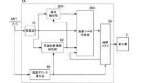
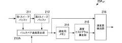
図1は第1の実施形態に係る探知画像生成装置1を含むレーダ装置3の構成を示すブロック図である。レーダ装置3は、探知画像生成装置1、表示器2、送信部4、送受切替部5、アンテナANTを備える。 FIG. 1 is a block diagram showing a configuration of a
送信部4は、探知信号を、方位分解能に応じて設定された繰り返し周期(1/PRF(送信の繰り返し周波数))で、順次出力する。探知信号は、所定のパルス幅、パルスの振幅、および変調パターンからなる信号で構成されている。具体的には、送信部4は、所定のパルス幅、パルスの振幅および変調パターンの信号を、局部発振回路(図示せず)から出力されるローカル信号と混合することで、探知信号を生成する。パルス幅、パルスの振幅および変調パターンは、距離分解能、探知距離等に応じて設定されている。探知信号は、送受切替部5を介してアンテナANTへ供給される。 The transmission unit 4 sequentially outputs detection signals at a repetition period (1 / PRF (transmission repetition frequency)) set according to the azimuth resolution. The detection signal is composed of a signal having a predetermined pulse width, pulse amplitude, and modulation pattern. Specifically, the transmission unit 4 generates a detection signal by mixing a signal having a predetermined pulse width, pulse amplitude, and modulation pattern with a local signal output from a local oscillation circuit (not shown). . The pulse width, pulse amplitude, and modulation pattern are set according to distance resolution, detection distance, and the like. The detection signal is supplied to the antenna ANT via the transmission /
アンテナANTは、船舶上の所定位置に設置されており、前記繰り返し周期(1/PRF)よりも十分に長い周期(スキャン周期)で回転しながら、探知信号(探知波)を外部(探知領域)へ送波する。アンテナANTは、探知波が探知領域内の物標や海面等に反射して得られる反射波を受波し、電気信号に変換することで受信信号を生成する。アンテナANTは、送受切替部5を介して受信信号を探知画像生成装置1へ出力する。この際、アンテナANTは、送受波方向を示すスイープ角度データを、受信信号とともに探知画像生成装置1へ出力する。 The antenna ANT is installed at a predetermined position on the ship and rotates the detection signal (detection wave) to the outside (detection region) while rotating at a cycle (scan cycle) sufficiently longer than the repetition cycle (1 / PRF). To wave. The antenna ANT generates a reception signal by receiving a reflected wave obtained by reflecting the detection wave to a target in the detection area, the sea surface, or the like, and converting the received wave into an electric signal. The antenna ANT outputs a received signal to the detected
探知画像生成装置1は、受信部10、速度検出部20、画像データ生成部30、描画アドレス発生部40、画像メモリ50を備える。 The detected
図2は受信部10の構成を示すブロック図である。受信部10は、増幅部101、直交検波部102、A/D変換部103、LPF104、スイープメモリ105を備える。増幅部101は、受信信号をAGC(Auto Gain Control)等で増幅し、直交検波部102へ出力する。直交検波部102は、上述の局部発振回路(図示せず)からの高周波信号と受信信号とを乗算することにより、直交検波を行う。直交検波により得られる複素型のエコー信号は、A/D変換部103へ出力される。A/D変換部103は、アナログ信号である複素型のエコー信号を所定のサンプリング周波数fsでサンプリングして、デジタルデータである複素型のエコーデータを生成し、LPF104へ出力する。LPF104では、ローパスフィルタ処理またはパルス圧縮処理を行う。探知信号が無変調信号の場合はローパスフィルタ処理を行い、変調信号の場合はパルス圧縮処理を行う。ローパスフィルタは、直交検波時に発生する高調波成分を除去する。パルス圧縮処理は、例えば、フーリエ変換部、マッチドフィルタ、逆フーリエ変換部を備え、直交検波部の出力信号を既知の方法でパルス圧縮する。LPF104は、ローパスフィルタ処理結果またはパルス圧縮処理結果をスイープメモリ105へ出力する。なお、パルス圧縮処理にローパスフィルタ処理の機能を持たせることも可能である。スイープメモリ105は、1スイープ分すなわち一回の探知信号の送信(1つの方位)に対して得られる距離方向に並ぶエコーデータを記憶するメモリであり、エコーデータを実時間で記憶する。スイープメモリ105は、記憶した1スイープ分のエコーデータを、次の探知信号の送信により得られるエコーデータが再び書き込まれるまでに、当該記憶した今回(n)の1スイープ分のエコーデータを、速度検出部20および画像データ生成部30へ出力する。なお、以下では、この1スイープ分のエコーデータ群を、スイープデータと称し、当該スイープデータを構成する各単位データをエコーデータと称する。また、スイープメモリ105は省略することができる。この場合、LPF104の出力が、速度検出部20および画像データ生成部30へ出力される。 FIG. 2 is a block diagram illustrating a configuration of the receiving
速度検出部20は、入力された注目位置に対応するエコーデータX[n]を含む所定の範囲のエコーデータから注目位置に存在する対象物の速度(以下、注目位置の速度と称する。)と、当該注目位置に対する周辺領域に存在する対象物の速度(以下、周辺領域の速度と称する。)とを検出する。速度検出部20は、注目位置の速度と周辺領域の速度との速度差Dif[ns]を算出し、画像データ生成部30へ出力する。なお、注目位置とは、演算の基準位置を意味し、例えば、複数の画素位置で順に速度検出を行う場合、注目位置(速度検出位置)は順次シフトしていく。 The
画像データ生成部30は、次の(式1)で示すスキャン相関処理を実現するハードウェアからなる。 The image
Y[ns]=α・X[ns]+β・Y[ns−1] −(式1)
ここで、X[ns]は注目位置の今回のエコーデータであり、Y[ns]は今回のスキャン相関処理により得られる注目位置の画像データである。Y[ns−1]は前回のスキャン相関処理により得られた注目位置の画像データであり、画像メモリ50から読み出される。α,βは、重み付け係数である。Y [ns] = α · X [ns] + β · Y [ns−1] − (Formula 1)
Here, X [ns] is the current echo data of the target position, and Y [ns] is the image data of the target position obtained by the current scan correlation process. Y [ns−1] is the image data of the target position obtained by the previous scan correlation process, and is read from the
画像データ生成部30は、速度検出部20から得た速度差Dif[ns]に応じて、スキャン相関処理の重み付け係数α、βを設定する。これにより、注目位置における今回のエコーデータX[ns]の値、および前回の画像データY[ns−1]の値が同じであっても、注目位置の速度Dif[ns]に応じて、今回の画像データY[ns]の値が変化する。 The image
画像データ生成部30は、スキャン相関処理によって算出された今回の画像データY[ns]を、画像メモリ50へ出力する。 The image
描画アドレス発生部40は、スイープの回転の中心を開始番地として、中心から周囲に向かって、所定方向(例えば船首方向)を基準としたアンテナ方位(角度)θTとスイープメモリ105の読み出し位置(距離方向位置)rとから、直交座標で配列された画像メモリ7におけるこの極座標位置(r,θT)に対応する画素を指定する番地を作成する。描画アドレス発生部40は、次の(式2−1)、(式2−2)を実現するハードウェアによって構成される。The
X=Xs+r・sinθT −(2−1)
Y=Ys+r・cosθT −(2−2)
ここで、X,Yは、画像メモリ50の画素を指定する番地であり、Xs,Ysはスイープの中心である。X = Xs + r · sin θT − (2-1)
Y = Ys + r · cos θT − (2-2)
Here, X and Y are addresses for designating pixels of the
画像メモリ50は、少なくとも1スキャン分の画像データを直交座標系で記憶可能な容量を有する。画像メモリ50には、画像データ生成部30から入力される画像データY[ns]が、描画アドレス発生部40から指定される番地[X,Y]に準じて、書き込まれる。そして、画像メモリ50では、図示しない表示制御部により、液晶パネル等からなる表示器2がラスター走査されると、このラスター走査に同期して、画像データY[ns]が読み出される。表示制御部は、読み出した画像データY[ns]に基づいて、輝度や色度を設定し、表示器2に画像を表示させる。 The
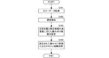
以上のような探知画像生成処理はプログラム化してコンピュータで実行することも可能である。この処理をフローで表すと、図3に示すようなフローになる。図3は、本発明の第1の実施形態に係る探知画像生成フローを示すフローチャートである。 The detected image generation process as described above can be programmed and executed by a computer. If this process is represented by a flow, it becomes a flow as shown in FIG. FIG. 3 is a flowchart showing a detection image generation flow according to the first embodiment of the present invention.
パルス状の送信信号による受信信号から複素型のエコーデータを取得する(S101)。エコーデータに基づいて、注目位置と周辺領域の速度を検出する(S102)。注目位置の速度と周辺領域の代表速度との速度差を算出し、速度差に応じて、スキャン相関処理の重み付け係数を設定する(S103)。重み付け係数が設定されると、今回のエコーデータと、前回のスキャン相関処理結果である前回の画像データとを重み付け加算すること(式1参照)でスキャン相関処理を行い、今回の画像データを算出する(S104)。 Complex-type echo data is acquired from the received signal based on the pulsed transmission signal (S101). Based on the echo data, the position of interest and the speed of the surrounding area are detected (S102). A speed difference between the speed of the target position and the representative speed of the surrounding area is calculated, and a weighting coefficient for scan correlation processing is set according to the speed difference (S103). When the weighting coefficient is set, scan correlation processing is performed by weighted addition of the current echo data and the previous image data which is the previous scan correlation processing result (see Equation 1), and the current image data is calculated. (S104).
このような処理により、上述のように、注目位置のエコーデータと前回の画像データが同じであっても、注目位置の速度によって、今回の画像データが異なる。これにより、次に示すような効果が得られる。 With this process, as described above, even if the echo data at the target position is the same as the previous image data, the current image data differs depending on the speed of the target position. Thereby, the following effects can be obtained.
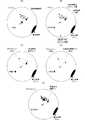
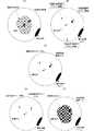
図4は、第1の実施形態に係る探知画像生成装置1および探知画像生成処理を用いた場合の効果を説明するための図である。図4(A)は、探知が行われる時点での海況を示す図である。図4(B)は、二種類のスキャン相関処理の適用範囲分布を示す図である。図4(C)は、本実施形態のスキャン相関処理を用いた場合の探知画面を示す図であり、図4(D)は、全探知領域に対して平均化のスキャン相関処理を用いた場合の探知画面を示す図である。図4(E)は、全探知領域に対して今回エコーデータの重みを重くするスキャン相関処理を用いた場合の探知画面を示す図である。なお、ここでは、説明を分かりやすくするために、自船は、船首方向が北方向であり、停止しているものとする。 FIG. 4 is a diagram for explaining an effect when the detection
図4(A)に示すように、自船の周囲に、静止物標(陸)、および、自船に向かう高速な高速移動物標(高速船)が存在する場合、注目位置を全領域の各画素位置に順次設定しながら、それぞれに上述のエコーデータによる速度検出を行うと、高速移動物標の速度が他の周辺領域の速度に対して十分に速くなることが分かる。これにしたがい、算出される高速移動物標の位置が注目位置となった場合、注目位置と周辺領域との速度差Dif[ns]は大きくなる。 As shown in FIG. 4 (A), when a stationary target (land) and a high-speed moving target (high-speed ship) heading toward the ship exist around the ship, It can be seen that the speed of the high-speed moving target is sufficiently higher than the speed of the other peripheral areas when the speed detection is performed on the above-described echo data while sequentially setting each pixel position. Accordingly, when the calculated position of the high-speed moving target becomes the attention position, the speed difference Dif [ns] between the attention position and the surrounding area becomes large.
速度差Dif[ns]が閾値以上であることを検出すると、高速移動物標の位置を含む極狭い所定範囲に領域(以下、近傍領域と称する。)に対して移動物標用のスキャン相関処理が適用される。移動物標用のスキャン相関処理とは、今回のエコーデータX[ns]の重みが重く、前回の画像データY[ns]の重みが軽いスキャン相関処理であり、言い換えれば(式1)のαが大きく、βが小さく設定されたスキャン相関処理である。これにより、今回のエコーデータが大きく反映された画像データが得られる。すなわち、今回取得したエコーデータの値が画像データの値に反映され、高速で移動する物標であっても抑圧されない画像データとなる。 When it is detected that the speed difference Dif [ns] is equal to or greater than the threshold value, the scan correlation process for the moving target is performed with respect to an extremely narrow predetermined range including the position of the high-speed moving target (hereinafter referred to as a neighboring region). Applies. The scan correlation process for the moving target is a scan correlation process in which the weight of the current echo data X [ns] is heavy and the weight of the previous image data Y [ns] is light, in other words, α in (Expression 1) Is a scan correlation process in which β is set large and β is set small. Thereby, image data in which the current echo data is largely reflected is obtained. That is, the value of the echo data acquired this time is reflected in the value of the image data, and the image data is not suppressed even if the target moves at high speed.
なお、近傍領域の広さは、適宜設定可能であり、例えば、速度差Difに応じて設定すればよい。具体的な例としては、速度差Difが大きければ、近傍領域の範囲を広くし、速度差Difが小さければ、近傍領域の範囲を狭くする。 Note that the size of the neighborhood region can be set as appropriate, and may be set according to the speed difference Dif, for example. As a specific example, if the speed difference Dif is large, the range of the neighboring region is widened. If the speed difference Dif is small, the range of the neighboring region is narrowed.
一方、高速移動物標の位置以外の周辺領域では、速度が全体として略同じであるため、周辺領域のどの位置であっても、注目位置と周辺領域との速度差Dif[ns]は小さくなる。このため、周辺領域のどの位置であっても、速度差Dif[ns]は閾値未満となる。この場合、移動物標用のスキャン相関処理とは異なるクラッタ等の不要反射波を抑圧するような通常処理用スキャン相関処理が適用される。ここでの通常処理用スキャン相関処理とは、例えば、今回のエコーデータX[ns]の重みが相対的に軽く、前回の画像データY[ns]の重みが相対的に重いスキャン相関処理であり、言い換えれば(式1)のαが相対的に小さく、βが相対的に大きく設定されたスキャン相関処理である。これにより、前回の画像データすなわちスキャン相関処理によって平均化された画像データの影響を大きく受ける画像データが得られる。 On the other hand, in the peripheral area other than the position of the high-speed moving target, the speed is substantially the same as a whole. Therefore, the speed difference Dif [ns] between the target position and the peripheral area is small at any position in the peripheral area. . For this reason, the speed difference Dif [ns] is less than the threshold value at any position in the peripheral region. In this case, scan correlation processing for normal processing that suppresses unnecessary reflected waves such as clutter, which is different from scan correlation processing for moving targets, is applied. The normal scan correlation processing here is, for example, scan correlation processing in which the weight of the current echo data X [ns] is relatively light and the weight of the previous image data Y [ns] is relatively heavy. In other words, this is a scan correlation process in which α in (Equation 1) is set to be relatively small and β is set to be relatively large. As a result, previous image data, that is, image data greatly influenced by the image data averaged by the scan correlation process is obtained.
なお、上述の処理を実現するには、移動物標用のスキャン相関処理の重み付け係数を、αm,βmとし、通常処理用(不要波抑圧用)のスキャン相関処理の重み付け係数を、αn,βnとすると、βm,βnが0でないとして、例えば、αm/βm>αn/βnとなるように設定すればよい。また、移動物標用のスキャン相関処理の重み付け係数に対してはβm=0とし、通常処理用スキャン相関処理の重み付け係数に対してはαn/βn<1としてもよい。In order to realize the above processing, the weighting coefficients of the scan correlation processing for the moving target are αm and βm, and the weighting coefficients of the scan correlation processing for normal processing (for unnecessary wave suppression) are αn, when the betan, betam, the betan is not zero, for example, may be set so thatα m / β m> α n / β n. Further, βm = 0 may be set for the weighting coefficient of the scan correlation process for the moving target, and αn / βn <1 may be set for the weighting coefficient of the scan correlation process for the normal process.
以上のような本実施形態に示す速度による重み付けの調整を行うことで、図4(C)に示すように、移動物標のエコーは抑圧されず、クラッタ等の不要反射波のエコーは抑圧され、静止物標エコーは抑圧されない探知画像を得ることができる。 By adjusting the weighting according to the speed shown in this embodiment as described above, as shown in FIG. 4C, the echo of the moving target is not suppressed, and the echo of the unnecessary reflected wave such as clutter is suppressed. In addition, it is possible to obtain a detection image in which stationary target echoes are not suppressed.
一方で、従来のスキャン相関処理では、速度による重み付けの調整を行っていないので、上述の平均化するスキャン相関処理を用いれば、図4(D)に示すように、移動物標がクラッタ等と同様に抑圧されてしまう。また、今回のエコーデータの重みを重くすれば、図4(E)に示すように、移動物標は抑圧されないが、同様にクラッタも抑圧されずに残ってしまう。 On the other hand, since the conventional scan correlation processing does not adjust the weighting based on the speed, if the above-described averaged scan correlation processing is used, as shown in FIG. It will be similarly suppressed. Further, if the weight of the echo data of this time is increased, the moving target is not suppressed as shown in FIG. 4E, but the clutter is also not suppressed and remains.
このように、本実施形態の構成および処理を用いれば、クラッタ等の不要反射波のエコーを抑圧しながら、移動物標のエコーを確実に残す探知画像を生成することができる。 As described above, by using the configuration and processing of the present embodiment, it is possible to generate a detection image that reliably leaves the echo of the moving target while suppressing the echo of unnecessary reflected waves such as clutter.
次に、速度検出部20の具体的な構成および速度検出について、図を参照して説明する。なお、以下では、速度検出方法を二種類説明する。 Next, a specific configuration and speed detection of the
<第1の速度検出方法>
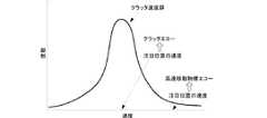
図5は、ドップラ周波数による速度検出を実現する速度検出部20vDのブロック図である。図6は、ドップラ周波数による速度検出概念を説明するための図である。なお、図6では、クラッタ領域内に移動物標が存在する場合を示している。<First speed detection method>
FIG. 5 is a block diagram of the
速度検出部20vDは、スイープバッファ201、ドップラフィルタバンク202、速度スペクトル算出部203、および速度差算出部204を備える。The
スイープバッファ201は、スイープメモリ105から出力されたスイープデータをバッファする。スイープバッファ201は、後段の離散フーリエ変換(DFT)を実現するのに必要なスイープ数を記憶する。スイープバッファ211は、常に最新の所定スイープ数のスイープデータを記憶する。なお、上述のようにスイープメモリ105を省略する場合には、LPF104の出力を所定スイープ数分記憶する。 The
ドップラフィルタバンク202には、スイープバッファ201にバッファされた複数のスイープデータが入力される。これら複数のスイープデータをドップラフィルタバンク202へ入力し、フィルタ処理を行うことで、図6に示すように、方位方向に並ぶ前記所定スイープ数のエコーデータに対して、DFT処理が行われる。このDFT処理は、例えば、サンプリング周期(1/fs)で設定される距離位置毎に行われる。これにより、図6の下図に示すように、距離位置毎のドップラ周波数fdのスペクトルが得られる。ここで、ドップラ周波数fdは、fd=±PRF/2の範囲をドップラバンク数で分割した分解能で得られる。 The
このような処理を行った場合、隣り合うスイープ間で、同じ距離位置にあるエコーデータ同士は、1/PRFの間隔だけ時間差があるため、注目位置に移動物標が存在すれば、この移動物標の自船方向への相対速度(距離方向に沿った相対速度)vに応じて、ドップラ周波数fdが発生する。なお、このようなドップラ周波数および速度は、船舶等の移動物標だけでなく、クラッタでも発生してしまう。 When such processing is performed, echo data at the same distance between adjacent sweeps has a time difference by an interval of 1 / PRF. Therefore, if there is a moving target at the position of interest, this moving object The Doppler frequency fd is generated according to the relative speed (relative speed along the distance direction) v in the direction of the ship. Such Doppler frequency and speed are generated not only by moving targets such as ships, but also by clutter.
しかしながら、例えば、図6の上図に示すように、クラッタ領域内に船舶等の移動物標が存在する場合、図6の下図に示すように、移動物標の領域を含まない距離位置RAと、移動物標の領域を含む距離位置RBで、スペクトルが異なる。具体的には、移動物標の領域を含まない距離位置RAでは、クラッタの速度に応じたドップラ周波数のみが得られる。一方、移動物標の領域を含む距離位置RBでは、クラッタの速度に応じたドップラ周波数と、移動物標の速度に応じたドップラ周波数とが得られる。このように出力されるドップラ周波数は、速度スペクトル算出部203へ出力される。However, for example, as shown in the upper diagram of FIG. 6, when a moving target such as a ship exists in the clutter region, as shown in the lower diagram of FIG. 6, the distance positionRA that does not include the moving target region. When, at a distance position RB including the region of the moving target, spectra are different. Specifically, only the Doppler frequency corresponding to the speed of the clutter is obtained at the distance positionRA that does not include the moving target area. On the other hand, the length position RB contains a region of the moving target, and the Doppler frequency corresponding to the speed of the clutter, and Doppler frequency corresponding to the speed of the moving target is obtained. The Doppler frequency output in this way is output to the velocity
速度スペクトル算出部203は、入力されるドップラ周波数から、注目位置を含むスイープの速度スペクトルを算出する。具体的には、注目位置(注目するエコーデータ)の速度をvとし、送信信号の波長λとすると、v=λ・fdによって、注目位置の速度vを算出することができる。この処理を、スイープ上の各エコーデータに対して実行する(注目位置を距離方向に移動させながら実行する)ことで、図6の下図においてドップラ周波数が速度に置き換わった速度スペクトルが得られる。速度スペクトル算出部203は、算出した速度スペクトルを、速度差検出部204へ出力する。 The velocity
速度差検出部204は、入力される速度スペクトルに基づいて、注目位置の速度差Difを算出する。具体的には、例えば、速度差検出部204は、注目位置スイープを方位方向の中心のスイープとして、所定スイープ分の速度スペクトルを一次記憶する。速度差検出部204は、注目位置の速度スペクトルに含まれるピーク速度を検出する。ここで、ピーク速度とは、速度スペクトルにおけるピークが発生する速度を意味する。速度差検出部204は、一次記憶した範囲を周辺領域(距離方向に沿った所定距離範囲および方位方向に沿った所定角度範囲)として、当該周辺領域に含まれる各位置の速度スペクトルを取得し、これらの速度スペクトルに含まれるピーク速度を検出する。なお、ここで、一度検出したピーク速度を位置毎に記憶しておけば、注目位置が変化する毎にピーク速度の検出を行う必要が無く、ピーク速度を直接読み出して、利用することもできる。 The speed
速度差検出部204は、当該周辺領域のピーク速度の平均値を算出する。この際、速度差検出部204は、周辺領域の各位置でのピーク速度において、その頻度が最も高いものの平均値を取るようにするとよい。これにより、周辺領域の各位置に、複数の速度ピークが存在しても、周辺領域の速度として最適な平均ピーク速度を算出することができる。 The speed
速度差検出部204は、周辺領域の平均ピーク速度と、注目位置のピーク速度との速度差を算出する。この際、注目位置に複数のピーク速度が存在すれば、それぞれに速度差を算出する。 The speed
このような処理を行った場合、図6のように周辺領域がクラッタ領域であれば、クラッタ速度が周辺領域の平均ピーク速度に相当する。したがって、注目位置(例えば、図6の特定スイープの距離RAの位置を参照)のエコーがクラッタのエコーのみであれば、注目位置のピーク速度と平均ピーク速度との速度差は、極小さく、略「0」となる。一方、注目位置(例えば、図6の特定スイープの距離RBの位置を参照)が移動物標のエコーを含んでいれば、注目位置の移動物標によるピーク速度と平均ピーク速度との間に速度差が生じる。When such processing is performed, if the peripheral area is a clutter area as shown in FIG. 6, the clutter speed corresponds to the average peak speed of the peripheral area. Therefore, if the echo at the target position (see, for example, the position of the distanceRA of the specific sweep in FIG. 6) is the clutter echo only, the speed difference between the peak speed and the average peak speed at the target position is extremely small, It is approximately “0”. On the other hand, the target position (e.g., see the position of the distance RB of a particular sweep of FIG. 6) if it contains an echo of the moving target, during the peak velocity due to the moving target position of interest and an average peak velocity A speed difference occurs.
速度差検出部204は、位置(エコーデータ)毎の速度差を画像データ生成部30へ出力する。 The speed
このように、上述の構成を用いれば、クラッタ内に移動物標が存在しても、クラッタの位置と移動物標の位置とで異なる速度差を検出することができる。そして、この速度差を用いることで、上述のような注目位置の速度に応じた重み付け係数の設定が可能になる。 As described above, when the above-described configuration is used, even if a moving target exists in the clutter, it is possible to detect a difference in speed between the position of the clutter and the position of the moving target. By using this speed difference, it is possible to set a weighting coefficient according to the speed of the target position as described above.
以上のような速度差の検出処理は、上述のように機能ブロック毎に実現することもできるが、図7に示すようなフローを実現するプログラムをコンピュータに実行させても、実現できる。図7は、ドップラ周波数による速度検出方法のフローチャートである。 The speed difference detection process as described above can be realized for each functional block as described above, but can also be realized by causing a computer to execute a program for realizing the flow shown in FIG. FIG. 7 is a flowchart of a speed detection method based on the Doppler frequency.
まず、所定スイープ分のスイープデータをバッファする(S121)。次に、バッファした所定数のスイープデータにおける同距離位置のエコーデータ群を用いて、DFT処理を実行することで、周波数スペクトルを算出する(S122)。 First, sweep data for a predetermined sweep is buffered (S121). Next, a frequency spectrum is calculated by performing DFT processing using echo data groups at the same distance position in a predetermined number of buffered sweep data (S122).
次に、注目位置の周波数スペクトルから速度スペクトルを算出し、注目位置のピーク速度を算出する(S123)。また、上述のように、周辺領域の平均ピーク速度を算出する(S124)。 Next, a speed spectrum is calculated from the frequency spectrum of the target position, and the peak speed of the target position is calculated (S123). Further, as described above, the average peak velocity in the peripheral region is calculated (S124).
次に、注目位置のピーク速度と、周辺領域の平均ピーク速度との速度差を算出する(S125)。 Next, the speed difference between the peak speed at the target position and the average peak speed in the surrounding area is calculated (S125).
<第2の速度検出方法>
図8は、パルスペア法に基づく自己相関処理による速度検出を実現する速度検出部20vPのブロック図である。図9は速度ヒストグラムを用いた速度差の検出概念を示すための速度ヒストグラム例を示す図である。<Second speed detection method>
FIG. 8 is a block diagram of the
速度検出部20vPは、第1スイープバッファ211、第2スイープバッファ212、パルスペア速度算出部213、速度用メモリ214、速度ヒストグラム算出部215、速度差検出部216を備える。 The speed detector 20vP includes a
第1スイープバッファ211は、スイープメモリ105から出力されたスイープデータをバッファし、次のスイープデータが入力されると、記憶中の第2スイープバッファ212へ出力する。第2スイープバッファ212は、第1スイープバッファ211から出力されたスイープデータを記憶する。 The
第1スイープバッファ211と第2スイープバッファ212は、それぞれに記憶したスイープデータをパルスペア速度算出部213へ、同期して出力する。なお、第1スイープバッファ211は、省略することができる。この場合、受信部10から出力されるエコーデータ(スイープデータ)と、第2スイープバッファ212からのスイープデータとを、パルスペア速度算出部213へ出力する。 The
パルスペア速度算出部213は、次に示す方法を用いて、各エコーデータの位置(注目位置)の速度を算出する。 The pulse pair
まず、速度測定概念について説明する。探知波の周波数をfoとし、波長をλとし、パルス長(時間長)をτとする。また、自船(アンテナ)に対して物標が近づく方向を正方向とした距離方向に沿った速度をvとする。また、送信繰り返し周期T(=1/PRF)とする。物標が速度vで自船に接近する場合、方位方向に隣り合うスイープ間では、物標と自船との距離は、1スイープ分すなわちvTだけ短くなる。すなわち、アンテナから探知波が送波されるタイミングから、物標に反射された反射波をアンテナANTで受波するタイミングまでの時間である往復伝搬時間Δt=2vT/cだけ、距離が短くなる。なお、cは光速である。 First, the concept of speed measurement will be described. The frequency of the detection wave is fo, the wavelength is λ, and the pulse length (time length) is τ. Further, the speed along the distance direction with the direction in which the target approaches the ship (antenna) as the positive direction is defined as v. The transmission repetition period T (= 1 / PRF) is set. When the target approaches the ship at a speed v, the distance between the target and the ship becomes shorter by one sweep, that is, vT, between sweeps adjacent in the azimuth direction. That is, the distance is shortened by the round-trip propagation time Δt = 2vT / c, which is the time from the timing at which the detection wave is transmitted from the antenna to the timing at which the reflected wave reflected by the target is received by the antenna ANT. C is the speed of light.
したがって、各スイープで送信開始後に同一時間だけ経過した時刻にサンプリングされる複素型のエコーデータの系列に注目すると、隣接するスイープ間での複素型のエコーデータの位相変化量Δφは、次の(式3)から得られる。 Therefore, when attention is paid to the complex echo data sequence sampled at the time when the same time has elapsed after the start of transmission in each sweep, the phase change amount Δφ of the complex echo data between adjacent sweeps is expressed by the following ( Obtained from equation 3).

この(式3)を変形することで、速度vを示す次の(式4)が得られる。 By transforming (Equation 3), the following (Equation 4) indicating the velocity v is obtained.
なお、ここで、位相変化量Δφの絶対値がπよりも小さいときには、隣接する複素型のエコーデータ間の位相差である偏角の差δφ(−π<δφ<π)と位相変化量Δφは一致する。しかしながら、位相変化量Δφの絶対値がπ以上の時には、位相変化量Δφと偏角の差δφとの差が2πの整数倍となってしまう。したがって、次の(式5)を満たすように、探知波(送信信号)の各要素(λ、PRF)を設定すれば、正確な位相変化量Δφを確実に一意的に算出することができる。 Here, when the absolute value of the phase change amount Δφ is smaller than π, the deviation δφ (−π <δφ <π), which is the phase difference between adjacent complex echo data, and the phase change amount Δφ Match. However, when the absolute value of the phase change amount Δφ is greater than or equal to π, the difference between the phase change amount Δφ and the difference in deviation δφ is an integral multiple of 2π. Therefore, if each element (λ, PRF) of the detection wave (transmission signal) is set so as to satisfy the following (Equation 5), an accurate phase change amount Δφ can be reliably calculated uniquely.
次に、パルスペア速度算出部213で実際に実行する処理について説明する。 Next, processing actually executed by the pulse pair
上述のように、(式3)、(式4)を用いれば、位相変化量Δφおよび速度vを算出することができるが、実際に観測できる位相には各種ノイズが重畳している。この影響を小さくするため、次に示す自己相関法を用いて、位相変化量Δφおよび速度vを算出する。 As described above, using (Equation 3) and (Equation 4), the phase change amount Δφ and the velocity v can be calculated, but various noises are superimposed on the actually observable phase. In order to reduce this influence, the phase change amount Δφ and the velocity v are calculated using the autocorrelation method described below.
物標が自船に向かって速度vで接近する場合、この物標の距離に対する距離番号(距離位置に相当)をn0とし、この物標からのエコーが最初に検出されるスイープの方位番号をk0とする。この時、方位方向に並ぶM個のエコーデータS[k0,n0],S[k0+1,n0],S[k0+2,n0],・・・・,S[k0+M−1,n0]が物標からのエコーを含むものとする。これらのエコーデータを、z[m]とすると、z[m]は次の(式6)で定義できる。If the target object is approaching a speed v toward the ship, the distance number for the distance of the target (distance corresponding to the position) and n0, the azimuth number of sweep echo from the target object is first detected Is k0. At this time, M echo data S [k0 , n0 ], S [k0 + 1 , n0 ], S [k0 + 2 , n0 ],..., S [k0 + M−1 ] arranged in the azimuth direction. , N0 ] includes the echo from the target. If these echo data are z [m], z [m] can be defined by the following (formula 6).
z[m]=S[k0+m,n0] (0≦m≦M−1) −(式6)
ここで、上述のように、探知波の周波数をfoとし、光速をcとすると、探知波が送波されるタイミングから物標に反射された反射波を受波するタイミングまでの探知波と反射波の伝搬距離である往復伝搬距離は、2vTだけ短くなる。z [m] = S [k0 + m , n0 ] (0 ≦ m ≦ M−1) − (Formula 6)
Here, as described above, when the frequency of the detection wave is fo and the speed of light is c, the detection wave and the reflection from the timing at which the detection wave is transmitted to the timing at which the reflected wave reflected by the target is received are reflected. The round-trip propagation distance, which is the wave propagation distance, is shortened by 2 vT.
したがって、z[m+1]の位相は、z[m]の位相を比較して、次の(式7)に表す位相変化量Δφpだけ大きくなる。 Therefore, the phase of z [m + 1] is increased by the phase change amount Δφp expressed by the following (Expression 7) by comparing the phases of z [m].
この(式7)を変形することで、速度vを示す次の(式8)が得られる。 By transforming (Equation 7), the following (Equation 8) indicating the speed v is obtained.
一方、1スイープあたりの位相変化量Δφpに対しては次に示す(式9)が成り立つことが一般的に知られている。 On the other hand, it is generally known that the following (Equation 9) holds for the phase change amount Δφp per sweep.
なお、z*[m]は、z[m]の複素共役であり、arg[ ]は、複素偏角を算出する演算式を示す。また、Δm,Lは、Δm+L≦Mを満たす任意の自然数である。Note that z* [m] is a complex conjugate of z [m], and arg [] represents an arithmetic expression for calculating a complex argument. Δm and L are arbitrary natural numbers that satisfy Δm + L ≦ M.
ここで、Δm=L=1とすると、上述のパルスペア法と同意の処理を実現でき、(式9)は、次の(式10)で表すことができる。 Here, when Δm = L = 1, the above-described pulse pair method and consent processing can be realized, and (Equation 9) can be expressed by the following (Equation 10).
したがって、当該(式10)を(式8)に代入することにより、次の(式11)が得られ、自己相関法による速度算出が可能になる。 Therefore, by substituting (Equation 10) into (Equation 8), the following (Equation 11) is obtained, and the speed can be calculated by the autocorrelation method.
このように、注目位置の複素型のエコーデータと、これに隣り合うスイープの複素型のエコーデータの自己相関処理を行うことで、当該注目位置の速度を算出することができる。 As described above, by performing autocorrelation processing between the complex type echo data of the target position and the complex type echo data of the adjacent sweep, it is possible to calculate the velocity of the target position.
パルスペア速度算出部213は、算出した速度を、速度用メモリ214および速度差検出部216へ出力する。 The pulse pair
速度用メモリ214は、パルスペア速度算出部213で算出された各位置の速度を所定範囲分記憶する。ここで、所定範囲とは、速度ヒストグラム算出部215で算出する周辺領域の範囲に相当する。 The
速度ヒストグラム算出部215は、速度用メモリ214から各位置の速度を読み出し、速度ヒストグラムを算出し、速度差検出部216へ出力する。なお、速度ヒストグラムの速度分解能は、クラッタ速度と、検出したい移動物標の速度とが異なる速度範囲内に収まるように仕様に応じて適宜設定すればよい。 The speed
速度差検出部216は、速度ヒストグラムから周辺領域の平均速度を算出し、当該周辺領域の代表速度に設定する。なお、速度ヒストグラムから平均速度を算出する方法としては、例えば、最も頻度の高い速度期間の中間値を平均速度にする。また、各速度期間の中間値に各速度期間の頻度を乗算して、重み付け平均を算出することで、平均速度を算出してもよい。さらには、ヒストグラムを用いず、速度用メモリ214から周辺領域内の各位置の速度を単に平均値処理することも可能である。ただし、この方法では、移動物標の速度も平均値処理に含まれるため、周辺領域の代表速度に誤差が生じてしまうため、ヒストグラムを用いた方が望ましい。 The speed
速度差検出部216は、注目位置を含む周辺領域の代表速度と注目位置の速度との速度差を算出する。この際、上述のヒストグラム算出処理等を行うため、代表速度が入力されるタイミングと注目位置の速度が入力されるタイミングとの間に時間差が生じるが、例えば、注目位置の極座標と周辺領域を示す極座標範囲との関係を予め設定しておき、注目位置に対応する周辺領域の代表速度が入力されたタイミングで、これらの速度を組み合わせて速度差を検出すればよい。 The speed
このような処理を用いると、周辺領域がクラッタ領域であれば、クラッタ速度が周辺領域の代表速度に相当する。したがって、注目位置のエコーがクラッタのエコーであれば、注目位置の速度と代表速度との速度差は、極小さく、略「0」となる。一方、注目位置が移動物標のエコーであれば、注目位置の速度と代表速度との間に速度差が生じる。 When such processing is used, if the surrounding area is a clutter area, the clutter speed corresponds to the representative speed of the surrounding area. Therefore, if the echo at the target position is a clutter echo, the speed difference between the speed at the target position and the representative speed is extremely small and is substantially “0”. On the other hand, if the target position is an echo of a moving target, a speed difference is generated between the speed of the target position and the representative speed.
速度差検出部216は、算出した速度差を画像データ生成部30へ出力する。 The speed
このようにパルスペア法(自己相関法)を用いても、クラッタの位置と移動物標の位置とで異なる速度差を検出することができる。そして、この速度差を用いることで、上述のような注目位置の速度に応じた重み付け係数の設定が可能になる。さらに、パルスペア法を用いた場合、バッファするスイープデータ数を少なくできるので、少ないリソースで速度差算出を行うことができる。 Thus, even if the pulse pair method (autocorrelation method) is used, it is possible to detect a difference in speed between the position of the clutter and the position of the moving target. By using this speed difference, it is possible to set a weighting coefficient according to the speed of the target position as described above. Further, when the pulse pair method is used, the number of sweep data to be buffered can be reduced, so that the speed difference can be calculated with less resources.
以上のような速度差の検出処理は、上述のように機能ブロック毎に実現することもできるが、図10に示すようなフローを実現するプログラムをコンピュータに実行させても、実現できる。図10は、パルスペア法に基づく自己相関処理による速度検出方法のフローチャートである。 The speed difference detection process as described above can be realized for each functional block as described above, but can also be realized by causing a computer to execute a program for realizing the flow shown in FIG. FIG. 10 is a flowchart of a speed detection method by autocorrelation processing based on the pulse pair method.
まず、隣り合う2つのスイープデータをバッファする(S131)。次に、バッファした2つのスイープデータのエコーデータの自己相関処理(パルスペア法による処理)を実行する(S132)。 First, two adjacent sweep data are buffered (S131). Next, autocorrelation processing (processing by the pulse pair method) of echo data of the two buffered sweep data is executed (S132).
次に、この自己相関処理結果を用いて、注目位置の速度を算出する(S133)。また、自己相関処理結果を用いて、注目位置を含む周辺領域の速度ヒストグラムを算出し、当該速度ヒストグラムから周辺領域の代表速度を算出する(S134)。 Next, the speed of the target position is calculated using the autocorrelation processing result (S133). Also, using the autocorrelation processing result, a speed histogram of the peripheral area including the target position is calculated, and a representative speed of the peripheral area is calculated from the speed histogram (S134).
次に、周辺領域の代表速度と注目位置の速度との速度差を算出する(S135)。 Next, a speed difference between the representative speed of the peripheral area and the speed of the target position is calculated (S135).
なお、上述の説明では、速度差が閾値以上であるか閾値未満であるかによって、重み付け係数を変更する場合を示したが、速度差に応じて重み付け係数を多段階に調整することも可能である。例えば、速度差が大きくなるほど、今回のエコーデータに対する重みをより重く設定するようにしてよい。これにより、速度差に応じた詳細な重み付け設定が可能になる。 In the above description, the weighting coefficient is changed depending on whether the speed difference is greater than or less than the threshold value. However, the weighting coefficient can be adjusted in multiple stages according to the speed difference. is there. For example, the weight for the current echo data may be set heavier as the speed difference increases. Thereby, detailed weight setting according to the speed difference becomes possible.
また、上述の説明において、速度ヒストグラムを算出する場合には、速度差を算出することなく、周辺領域の速度範囲となる確率を算出することで、重み付け係数の設定に利用できる。例えば、注目位置の速度が周辺領域の速度範囲に属する確率が、所定閾値以下になる場合に、当該注目位置の重み付け係数を、周辺領域の重み付け係数と異ならせる。さらには、注目位置の速度が周辺領域の速度範囲に属する確率に応じて、重み付け係数を変化させてもよい。 In the above description, when calculating the speed histogram, it is possible to set the weighting coefficient by calculating the probability of being in the speed range of the surrounding area without calculating the speed difference. For example, when the probability that the speed of the attention position belongs to the speed range of the surrounding area is equal to or less than a predetermined threshold, the weighting coefficient of the attention position is made different from the weighting coefficient of the surrounding area. Furthermore, the weighting coefficient may be changed according to the probability that the speed of the target position belongs to the speed range of the surrounding area.
次に、本発明の第2の実施形態に係る探知画像生成装置1Aについて、図を参照して説明する。図11は、本発明の第2の実施形態に係る探知画像生成装置1Aの構成を示すブロック図である。図12は、ドップラ周波数による速度検出を実現する速度検出部20AvDのブロック図である。図13は、パルスペア法に基づく自己相関処理による速度検出を実現する速度検出部20AvPのブロック図である。Next, a detection
本実施形態の探知画像生成装置1Aは、第1の実施形態に示した探知画像生成装置1に対して、海面反射領域検出部60を追加したものである。したがって、以下では、異なる箇所のみを説明する。 The detection
海面反射領域検出部60には、受信部10から出力されるスイープデータが入力される。海面反射領域検出部60には、描画アドレスも入力される。海面反射領域検出部60の詳細な処理は、本願と同一出願人が既に出願している特願2007−226904(特開2009−58433号公報)に記載されており、ここでは説明を省略する。 Sweep data output from the
海面反射領域検出部60は、判断対象の位置のエコーデータの不安定度を検出し、不安定度が所定閾値以上であると、当該判断対象位置が海面反射領域(クラッタ領域)内であると判断する。海面反射領域検出部60は、判断対象位置が海面反射領域内であると判断すると、海面反射領域設定用データBn=「1」とし、判断対象位置が海面反射領域外であると判断すると、海面反射領域設定用データBn=「0」として、出力する。海面反射領域設定用データBnは、画像データ生成部30A、速度検出部20Aへ出力される。速度検出部20Aは、ドップラ周波数を用いる場合には、図12に示す速度検出部20AvDで実現でき、パルスペア法を用いる場合には、図13に示す速度検出部20AvPで実現できる。The sea surface reflection
速度検出部20AvDは、図12に示すように、スイープバッファ201、ドップラフィルタバンク202、速度スペクトル算出部203A、速度差検出部204を備える。なお、スイープバッファ201、ドップラフィルタバンク202、速度スペクトル算出部203A、速度差検出部204の基本処理は、第1の実施形態に示した速度検出部20vDと同じである。The
海面反射領域設定用データBnは、速度スペクトル203Aへ与えられる。速度スペクトル算出部203Aは、海面反射領域設定用データBnが「1」の場合のみ、速度スペクトルを算出する。すなわち、速度スペクトル算出部203Aは、注目位置が海面反射領域内にある場合にのみ、注目位置と当該注目位置の周辺領域の速度スペクトルの算出を行う。これにより、全周囲の全ての位置の速度算出を行うよりも、少ないリソースで、必要とする範囲の速度を算出することができる。 The sea surface reflection region setting data Bn is given to the
また、速度検出部20AvPは、図13に示すように、第1スイープバッファ211、第2スイープバッファ212、パルスペア速度算出部213A、速度用メモリ214、速度ヒストグラム算出部215、速度差検出部216を備える。なお、第1スイープバッファ211、第2スイープバッファ212、パルスペア速度算出部213A、速度用メモリ214、速度ヒストグラム算出部215、速度差検出部216の基本処理は、第1の実施形態に示した速度検出部20vPと同じである。Further, as shown in FIG. 13, the
海面反射領域設定用データBnは、パルスペア速度算出部213Aへ与えられる。パルスペア速度算出部213Aは、海面反射領域設定用データBnが「1」の場合のみ、速度を算出する。すなわち、パルスペア速度算出部213Aは、注目位置が海面反射領域内にある場合にのみ、注目位置の速度と当該注目位置の周辺領域の代表速度の算出を行う。これにより、全周囲の全ての位置の速度算出を行うよりも、少ないリソースで、必要とする範囲の速度を算出することができる。 The sea surface reflection area setting data Bn is given to the pulse pair
画像データ生成部30Aは、海面反射領域設定用データBnが「0」の場合、すなわち、対象の画素が海面反射領域外であると判断された場合、海面反射抑圧の必要がないため、今回のエコーデータX[ns]の重みαを重くし、前回の画像データY[ns]の重みを軽くする(α>β)スキャン相関処理を実行する。これにより、海面反射領域外に対しては、探知タイミングでの状況に応じた探知画像データを得ることができる。 When the sea surface reflection area setting data Bn is “0”, that is, when it is determined that the target pixel is outside the sea surface reflection area, the image
画像データ生成部30Aは、海面反射領域設定用データBnが「1」の場合、基本的には、該当する画素に対する重み付け係数を、海面反射抑圧用に設定する。この場合、具体的には、画像データ生成部30Aは、今回のエコーデータX[ns]の重みαを軽くし、前回の画像データY[ns]の重みを重くする(α≪β)スキャン相関処理を実行する。これにより、海面反射の抑圧を行う。ただし、画像データ生成部30Aは、速度検出部20Aから取得した速度差が所定閾値以上であると、対象とする画素に対しては、今回のエコーデータX[ns]の重みαを重くし、前回の画像データY[ns]の重みを軽くする(α>β)スキャン相関処理を実行する。これにより、海面反射を抑圧しながら海面反射領域内に存在する移動物標が抑圧されない探知画像データを得ることができる。 When the sea surface reflection region setting data Bn is “1”, the image
以上のような本実施形態の探知画像生成処理はプログラム化してコンピュータで実行することも可能である。この処理をフローで表すと、図14に示すようなフローになる。図14は、本発明の第2の実施形態に係る探知画像生成フローを示すフローチャートである。 The detection image generation processing of the present embodiment as described above can be programmed and executed by a computer. If this process is represented by a flow, it becomes a flow as shown in FIG. FIG. 14 is a flowchart showing a detection image generation flow according to the second embodiment of the present invention.
パルス状の送信信号による受信信号から複素型のエコーデータを取得する(S201)。次に、エコーデータに基づいて、海面反射領域を検出する(S202)。注目位置が海面反射領域外であれば(S203:No)、海面反射領域外用の重み付けによるスキャン相関処理を実行する(S204)。 Complex-type echo data is acquired from the received signal based on the pulsed transmission signal (S201). Next, a sea surface reflection area is detected based on the echo data (S202). If the position of interest is outside the sea surface reflection area (S203: No), scan correlation processing by weighting outside the sea surface reflection area is executed (S204).
注目位置が海面反射領域内であれば(S203:Yes)、エコーデータに基づいて、注目位置と周辺領域の速度を検出する(S205)。次に、注目位置の速度と周辺領域の代表速度との速度差を算出し、速度差に応じて、スキャン相関処理の重み付け係数を設定する(S206)。重み付け係数が設定されると、今回のエコーデータと、前回のスキャン相関処理結果である前回の画像データとを重み付け加算すること(式1参照)でスキャン相関処理を行い、今回の画像データを算出する(S207)。 If the target position is within the sea surface reflection area (S203: Yes), the speed of the target position and the peripheral area is detected based on the echo data (S205). Next, a speed difference between the speed of the target position and the representative speed of the surrounding area is calculated, and a weighting coefficient for scan correlation processing is set according to the speed difference (S206). When the weighting coefficient is set, scan correlation processing is performed by weighted addition of the current echo data and the previous image data which is the previous scan correlation processing result (see Equation 1), and the current image data is calculated. (S207).
以上のように、本実施形態の構成および処理を用いることで、次のような探知画像生成処理を実現できる。図15は、第2の実施形態に係る探知画像生成装置1Aおよび探知画像生成処理を用いた場合の効果を説明するための図である。図15(A)は、探知が行われる時点での海況を示す図である。図15(B)は、スキャン相関処理の適用範囲分布を示す図である。図15(C)は、本実施形態のスキャン相関処理を用いた場合の探知画面を示す図であり、図15(D)は、全探知領域に対して平均化のスキャン相関処理を用いた場合の探知画面を示す図である。図15(E)は、全探知領域に対して今回エコーデータの重みを重くするスキャン相関処理を用いた場合の探知画面を示す図である。なお、ここでも、説明を分かりやすくするために、自船は、船首方向が北方向であり、停止しているものとする。 As described above, the following detection image generation processing can be realized by using the configuration and processing of the present embodiment. FIG. 15 is a diagram for explaining an effect when the detection
図15(A)に示すように、自船の周囲に、静止物標(陸)、および、自船に向かう高速な高速移動物標(高速船)が存在し、且つ自船周りに海面反射が存在する場合、上述のように海面反射領域を検出することで、図15(B)に示すように、海面反射領域内用のスキャン相関処理の適用範囲と、海面反射領域外用のスキャン相関処理の適用範囲とを識別することができる。さらに、速度差に応じて、移動物標の近傍に対して移動物標用のスキャン相関処理を適用することができる。 As shown in FIG. 15A, a stationary target (land) and a high-speed moving target (high-speed ship) heading toward the ship exist around the ship, and the sea surface is reflected around the ship. 15B, by detecting the sea surface reflection area as described above, the application range of the scan correlation process for the sea surface reflection area and the scan correlation process for the outside of the sea surface reflection area as shown in FIG. Can be distinguished from the scope of application. Furthermore, the scan correlation process for moving targets can be applied to the vicinity of the moving target according to the speed difference.
これにより、図15(C)に示すように、海面反射を抑圧しながらも、海面反射領域内の移動物標のエコーは抑圧せず、海面反射領域外に対しては、海況に応じた静止物標エコーを含む各物標エコー等を抑圧しない探知画像を得ることができる。 As a result, as shown in FIG. 15C, while suppressing the sea surface reflection, the echo of the moving target in the sea surface reflection area is not suppressed, and the outside of the sea surface reflection area is stationary according to the sea condition. A detection image that does not suppress each target echo including the target echo can be obtained.
一方で、従来のスキャン相関処理では、速度による重み付けの調整を行っていないので、上述の平均化するスキャン相関処理を用いれば、図15(D)に示すように、海面反射の抑圧とともに、移動物標も同様に抑圧されてしまう。また、海面反射領域内の移動物標を抑圧させないために今回のエコーデータの重みを重くすれば、図15(E)に示すように、移動物標は抑圧されないが、同様にクラッタも抑圧されずに残ってしまう。 On the other hand, the conventional scan correlation process does not adjust the weighting according to the speed. Therefore, if the above-described averaged scan correlation process is used, as shown in FIG. The target is similarly suppressed. Further, if the weight of the echo data of this time is increased in order not to suppress the moving target in the sea surface reflection area, the moving target is not suppressed as shown in FIG. 15E, but the clutter is also suppressed similarly. Will remain.
このように、本実施形態の構成および処理を用いれば、クラッタ等の不要反射波のエコーを抑圧しながら、移動物標のエコーを確実に残す探知画像を生成することができる。 As described above, by using the configuration and processing of the present embodiment, it is possible to generate a detection image that reliably leaves the echo of the moving target while suppressing the echo of unnecessary reflected waves such as clutter.
次に、本発明の第3の実施形態に係る探知画像生成装置1Bについて、図を参照して説明する。図16は、本発明の第3の実施形態に係る探知画像生成装置1Bの構成を示すブロック図である。本実施形態の探知画像生成装置1Bは、第1の実施形態に示した探知画像生成装置1に対して、振幅検出部70を追加したものである。したがって、以下では、異なる箇所のみを説明する。 Next, a detection
振幅検出部70には、受信部10から出力されるスイープデータが入力される。振幅検出部70は、スイープデータを構成する各エコーデータの振幅(複素型エコーデータの絶対値)を算出する。振幅検出部70は、予め物標検出用の振幅閾値を記憶しており、各エコーデータの振幅と振幅閾値とを比較する。振幅検出部70は、振幅閾値以上の振幅からなるエコーデータを検出すると、当該エコーデータに対応する位置を注目位置として、速度検出部20Bへ出力する。 Sweep data output from the
速度検出部20Bは、振幅検出部70で物標位置と検出された注目位置に対して、速度差を算出し、画像データ生成部30Bへ出力する。なお、速度検出部20Bは、上述の各実施形態に示しように、ドップラ周波数による速度算出を用いても、パルスペア法による速度算出を用いてもどちらでもよい。このような物標検出位置のみで速度を算出することにより、少ないリソースで必要とする範囲の速度を算出することができる。 The
以上のような本実施形態の探知画像生成処理はプログラム化してコンピュータで実行することも可能である。この処理をフローで表すと、図17に示すようなフローになる。図17は、本発明の第3の実施形態に係る探知画像生成フローを示すフローチャートである。 The detection image generation processing of the present embodiment as described above can be programmed and executed by a computer. If this processing is represented by a flow, the flow is as shown in FIG. FIG. 17 is a flowchart showing a detection image generation flow according to the third embodiment of the present invention.
パルス状の送信信号による受信信号から複素型のエコーデータを取得する(S301)。次に、エコーデータの振幅検出を行い、物標検出に相当する処理を行う(S302)。注目位置のエコーデータの振幅が所定の振幅閾値未満であれば(S303:No)、物標非検出領域用のスキャン相関処理を実行する(S304)。物標非検出領域用のスキャン相関処理とは、第1の実施形態に示した抑圧用の重み付けと同等の重み付けで実行するスキャン相関処理である。 Complex-type echo data is acquired from the received signal based on the pulsed transmission signal (S301). Next, amplitude detection of echo data is performed, and processing corresponding to target detection is performed (S302). If the amplitude of the echo data of the target position is less than the predetermined amplitude threshold (S303: No), the scan correlation process for the target non-detection region is executed (S304). The scan correlation process for the target non-detection region is a scan correlation process executed with a weighting equivalent to the weighting for suppression shown in the first embodiment.
注目位置のエコーデータの振幅が振幅閾値以上であれば(S303:Yes)、エコーデータに基づいて、注目位置と周辺領域の速度を検出する(S305)。次に、注目位置の速度と周辺領域の代表速度との速度差を算出し、速度差に応じて、スキャン相関処理の重み付け係数を設定する(S306)。重み付け係数が設定されると、今回のエコーデータと、前回のスキャン相関処理結果である前回の画像データとを重み付け加算すること(式1参照)でスキャン相関処理を行い、今回の画像データを算出する(S307)。 If the amplitude of the echo data at the target position is greater than or equal to the amplitude threshold (S303: Yes), the speed of the target position and the surrounding area is detected based on the echo data (S305). Next, a speed difference between the speed of the target position and the representative speed of the surrounding area is calculated, and a weighting coefficient for scan correlation processing is set according to the speed difference (S306). When the weighting coefficient is set, scan correlation processing is performed by weighted addition of the current echo data and the previous image data which is the previous scan correlation processing result (see Equation 1), and the current image data is calculated. (S307).
以上のように、本実施形態の構成および処理を用いても、クラッタ等の不要反射波のエコーを抑圧しながら、移動物標のエコーを確実に残す探知画像を生成することができる。 As described above, even if the configuration and processing of this embodiment are used, it is possible to generate a detection image that reliably leaves the echo of the moving target while suppressing the echo of unnecessary reflected waves such as clutter.
次に、本発明の第4の実施形態に係る探知画像生成装置1Cについて、図を参照して説明する。図18は、本発明の第4の実施形態に係る探知画像生成装置1Cの構成を示すブロック図である。本実施形態の探知画像生成装置1Cは、第2の実施形態に示した探知画像生成装置1Aと第3の実施形態に示した探知画像生成装置1Cとを組み合わせたものである。したがって、以下では、第2、第3実施形態の探知画像生成装置1A,1Bと異なる箇所のみを説明する。 Next, a detection image generation device 1C according to a fourth embodiment of the present invention will be described with reference to the drawings. FIG. 18 is a block diagram showing a configuration of a detected image generation apparatus 1C according to the fourth embodiment of the present invention. A detection image generation device 1C of the present embodiment is a combination of the detection
海面反射領域検出部60は、第2の実施形態に示したように、スイープデータを構成するエコーデータから海面反射領域を検出し、海面反射領域設定用データBnを生成し、速度検出部20Cおよび画像データ生成部30Cへ出力する。 As shown in the second embodiment, the sea surface reflection
振幅検出部70は、第3の実施形態に示したように、スイープデータを構成する各エコーデータの振幅(複素型エコーデータの絶対値)を算出し、各エコーデータの振幅と振幅閾値とを比較する。振幅検出部70は、振幅閾値以上の振幅からなるエコーデータを検出すると、当該エコーデータに対応する位置を注目位置として、速度検出部20Cへ出力する。 As shown in the third embodiment, the
速度検出部20Cは、海面反射領域設定用データBnが「1」すなわち海面反射領域内であり、且つ振幅検出部70で物標位置と検出された注目位置に対して、速度差を算出し、画像データ生成部30Cへ出力する。なお、速度検出部20Cは、上述の各実施形態に示しように、ドップラ周波数による速度算出を用いても、パルスペア法による速度算出を用いてもどちらでもよい。このような海面反射領域内の物標検出位置のみで速度を算出することにより、さらに少ないリソースで必要とする範囲の速度を算出することができる。 The
以上のような本実施形態の探知画像生成処理はプログラム化してコンピュータで実行することも可能である。この処理をフローで表すと、図19に示すようなフローになる。図19は、本発明の第4の実施形態に係る探知画像生成フローを示すフローチャートである。 The detection image generation processing of the present embodiment as described above can be programmed and executed by a computer. If this processing is represented by a flow, the flow is as shown in FIG. FIG. 19 is a flowchart showing a detection image generation flow according to the fourth embodiment of the present invention.
パルス状の送信信号による受信信号から複素型のエコーデータを取得する(S401)。次に、エコーデータに基づいて、海面反射領域を検出する(S402)。注目位置が海面反射領域外であれば(S403:No)、海面反射領域外用の重み付けによるスキャン相関処理を実行する(S404)。 Complex-type echo data is acquired from the received signal based on the pulsed transmission signal (S401). Next, a sea surface reflection area is detected based on the echo data (S402). If the target position is outside the sea surface reflection area (S403: No), scan correlation processing by weighting outside the sea surface reflection area is executed (S404).
注目位置が海面反射領域内であれば(S403:Yes)、エコーデータの振幅検出を行い、物標検出に相当する処理を行う(S405)。注目位置のエコーデータの振幅が所定の振幅閾値未満であれば(S406:No)、海面反射領域内用のスキャン相関処理を実行する(S407)。 If the target position is within the sea surface reflection region (S403: Yes), the amplitude of the echo data is detected, and processing corresponding to target detection is performed (S405). If the amplitude of the echo data at the target position is less than the predetermined amplitude threshold value (S406: No), the scan correlation process for the sea surface reflection area is executed (S407).
注目位置のエコーデータの振幅が振幅閾値以上であれば(S406:Yes)、エコーデータに基づいて、注目位置と周辺領域の速度を検出する(S408)。次に、注目位置の速度と周辺領域の代表速度との速度差を算出し、速度差に応じて、スキャン相関処理の重み付け係数を設定する(S409)。重み付け係数が設定されると、今回のエコーデータと、前回のスキャン相関処理結果である前回の画像データとを重み付け加算すること(式1参照)でスキャン相関処理を行い、今回の画像データを算出する(S410)。 If the amplitude of the echo data at the target position is greater than or equal to the amplitude threshold (S406: Yes), the speed of the target position and the surrounding area are detected based on the echo data (S408). Next, a speed difference between the speed of the target position and the representative speed of the surrounding area is calculated, and a weighting coefficient for scan correlation processing is set according to the speed difference (S409). When the weighting coefficient is set, scan correlation processing is performed by weighted addition of the current echo data and the previous image data which is the previous scan correlation processing result (see Equation 1), and the current image data is calculated. (S410).
以上のように、本実施形態の構成および処理を用いても、クラッタ等の不要反射波のエコーを抑圧しながら、移動物標のエコーを確実に残す探知画像を生成することができる。 As described above, even if the configuration and processing of this embodiment are used, it is possible to generate a detection image that reliably leaves the echo of the moving target while suppressing the echo of unnecessary reflected waves such as clutter.
次に、本発明の第5の実施形態に係る探知画像生成装置1Dについて、図を参照して説明する。図20は、本発明の第5の実施形態に係る探知画像生成装置1Dの構成を示すブロック図である。本実施形態の探知画像生成装置1Dは、第4の実施形態に示した探知画像生成装置1Dに対して、データ連続性検出部80を追加したものである。したがって、以下では、第4の実施形態の探知画像生成装置1Cと異なる箇所のみを説明する。 Next, a detection
データ連続性検出部80の詳細な処理は、本願と同一出願人が既に出願している特願2007−226904(特開2009−58433号公報)に記載されており、ここでは説明を省略する。データ連続性検出部80は、注目位置のエコーデータの平面的な連続性を検出する。概略的に説明すると、連続性とは、注目位置を略中心とする距離方向および方位方向へ所定の範囲内にある各位置のエコーデータが物標検出閾値以上である数によって決定される。データ連続性検出部80は、物標検出閾値以上のエコーデータ数が所定個数以上であれば連続性データAn=「1」を設定し、物標検出閾値以上のエコーデータ数が所定個数未満であれば連続性データAn=「1」を設定する。データ連続性検出部80は、連続性データAnを画像データ生成部30Dへ出力する。 Detailed processing of the data
画像データ生成部30Dは、海面反射領域設定用データBnと、速度差と、連続性データAnに基づいて、次の(式12)に示すスキャン相関処理を実行する。 The image
Y[ns]=α・γ・X[ns]+β・Y[ns−1] −(式12)
なお、α,βは、上述のように、海面反射領域設定用データBnと速度差とに基づいて設定される。γは連続性データAnによって設定される。この際、連続性データAnが「1」の場合に採用するγ1は、連続性データAnが「0」の場合に採用するγ2よりも大きくなるよう(γ1>γ2)に設定する。これにより、さらに移動物標は抑圧することなく、海面反射等のクラッタを抑圧することができる。Y [ns] = α · γ · X [ns] + β · Y [ns−1] − (Formula 12)
Note that α and β are set based on the sea surface reflection region setting data Bn and the speed difference as described above. γ is set by continuity data An. At this time, γ1 employed when the continuity data An is “1” is set to be larger than γ2 employed when the continuity data An is “0” (γ1 > γ2 ). . Thereby, the clutter such as sea surface reflection can be suppressed without further suppressing the moving target.
ところで、上述の各実施形態では、自船は船首方向が北方向であって、大地に対して停止しているものとして説明したが、次の速度補正概念を用いることで、船首方向および自船速度(対地船速)に影響されることなく、物標が自船方向に向かう速度vを算出することができる。図21は、速度補正概念を説明するための図である。 By the way, in each above-mentioned embodiment, although the own ship demonstrated that the bow direction was a north direction and stopped with respect to the earth, by using the following speed correction concept, a bow direction and own ship are demonstrated. The speed v at which the target moves in the direction of the ship can be calculated without being influenced by the speed (ground ship speed). FIG. 21 is a diagram for explaining the concept of speed correction.
図21に示すように、自船速度をVoとし、物標が自船方向に向かう速度Vrとする。また、アンテナ位置から北方向を結ぶラインとアンテナ位置から船首方向を結ぶラインの成す角(時計回りの角度)である船首方位をθhとし、北方向を基準とした反時計回りの針路をθcとする。さらに、船首方向を基準としたアンテナの送信方向を時計回りの角度で示すアンテナ方位をθTとする。As shown in FIG. 21, the ship speed is Vo, and the target is a speed Vr toward the ship direction. Further, the heading which is the angle (clockwise angle) formed by the line connecting the antenna position to the north direction and the line connecting the antenna position to the bow direction is θh, and the counterclockwise course based on the north direction is θc . Furthermore, let θT be the antenna orientation that indicates the antenna transmission direction with respect to the bow direction as a clockwise angle.
このような設定を行うと、自船の物標方向の速度である速度補正量Vcは、次の(式13)で得られる。 When such setting is performed, the speed correction amount Vc that is the speed of the ship in the target direction is obtained by the following (Equation 13).
したがって、補正後の物標の速度Vocは、次の(式14)で得られる。 Therefore, the corrected target velocity Voc is obtained by the following (Expression 14).
この補正後の物標の速度Vocを、上述の各位置の速度vとして用いれば、自船の動きに影響されることなく、上述の速度に応じた重み付け係数の設定を行うことができる。 If the corrected target velocity Voc is used as the velocity v at each position, the weighting coefficient can be set according to the velocity without being affected by the movement of the ship.
なお、上述の説明では、海面反射(シークラッタ)を例に説明したが、他のクラッタ、例えばレインクラッタの場合にも、上述の構成を適用し、同様の作用効果を得ることができる。 In the above description, sea surface reflection (sea clutter) has been described as an example. However, in the case of other clutters, for example, rain clutter, the above-described configuration can be applied to obtain the same operation and effect.
また、上述の説明では、クラッタ内に存在する移動物標に適用する例を示したが、クラッタ領域外においても同様に、上述の実施形態の構成および処理を用いて、移動物標の近傍領域のみに、他の領域と異なる重み付け係数を設定することもできる。 Further, in the above description, an example of applying to a moving target existing in a clutter has been shown. Similarly, a region near a moving target is also used outside the clutter region by using the configuration and processing of the above-described embodiment. It is also possible to set a weighting coefficient different from that of other areas.
また、上述の説明では、周辺領域の速度を、エコーデータから算出している。しかしながら、実験、シミュレーション、過去の観測結果等からクラッタとして検出し得る速度範囲を取得しておけば、当該速度範囲に該当しない速度が検出された位置に対して、上述の実施形態と同様に、周辺領域とは異なる重み付け係数を設定するようにすることもできる。 In the above description, the speed of the surrounding area is calculated from the echo data. However, if a speed range that can be detected as clutter is acquired from experiments, simulations, past observation results, etc., the position where a speed that does not fall within the speed range is detected, as in the above embodiment, A weighting coefficient different from that in the surrounding area may be set.
また、上述の説明では、距離方向に沿ったドップラ速度を算出して、スキャン相関処理の重み付けに利用する場合を示した。しかしながら、距離方向以外の方向のドップラ速度(例えば、移動物標の距離方向および方位方向を含む実速度のドップラ速度)を用いても同様の重み付け設定を行うことができる。 In the above description, the Doppler velocity along the distance direction is calculated and used for weighting the scan correlation process. However, the same weighting setting can be performed using Doppler speeds in directions other than the distance direction (for example, actual Doppler speeds including the distance direction and the azimuth direction of the moving target).
距離方向以外の方向のドップラ速度の算出方法としては、例えば、異なる位置に複数のアンテナを設置し、それぞれに算出したドップラ速度をベクトルで合成する方法がある。この際、少なくとも二つのアンテナを用いればよいが、互いに一直線上に並ばない三つ以上のアンテナを用いることで、確実に実速度に応じたドップラ速度を算出することができる。 As a method of calculating the Doppler velocity in directions other than the distance direction, for example, there is a method of installing a plurality of antennas at different positions and combining the calculated Doppler velocities with vectors. At this time, at least two antennas may be used, but by using three or more antennas that are not aligned with each other, the Doppler speed according to the actual speed can be reliably calculated.
さらに、移動物標が方位分解能よりも大きいものであれば、単独のアンテナであっても実速度に応じたドップラ速度の算出は可能である。この場合、単独のアンテナで異なる複数の方位で得られた距離方向のドップラ速度のベクトル量や方位に対するベクトル量の変化から、実速度に応じたドップラ速度を算出することができる。 Furthermore, if the moving target is larger than the azimuth resolution, the Doppler speed can be calculated according to the actual speed even with a single antenna. In this case, the Doppler velocity corresponding to the actual velocity can be calculated from the vector amount of the Doppler velocity in the distance direction obtained from a plurality of different azimuths with a single antenna and the change in the vector amount with respect to the azimuth.
1,1A,1B,1C,1D:探知画像生成装置、2:表示器、3:レーダ装置、4:送信部、5:送受切替部、
10:受信部、20,20vD,20vP,20A,20AvD,20AvP,20B,20C:速度検出部、30:画像データ生成部、40:描画アドレス発生部、50:画像メモリ、60:海面反射領域検出部、70:振幅検出部、80:データ連続性検出部、
101:増幅部、102:直交検波部、103:A/D変換部、104:LPF、105:スイープメモリ、
201:スイープバッファ、202:ドップラフィルタバンク、203:速度スペクトル算出部、204:速度差検出部、
211:第1スイープバッファ、212:第2スイープバッファ、213:パルスペア速度算出部、214:速度用メモリ、215:速度ヒストグラム算出部、216:速度差検出部1, 1A, 1B, 1C, 1D: Detected image generation device, 2: Display, 3: Radar device, 4: Transmission unit, 5: Transmission / reception switching unit,
10: Reception unit, 20, 20vD , 20vP , 20A, 20AvD , 20AvP , 20B, 20C: Speed detection unit, 30: Image data generation unit, 40: Drawing address generation unit, 50: Image memory, 60: Sea surface reflection area detection unit, 70: amplitude detection unit, 80: data continuity detection unit,
101: Amplifying unit, 102: Quadrature detection unit, 103: A / D conversion unit, 104: LPF, 105: Sweep memory,
201: sweep buffer, 202: Doppler filter bank, 203: velocity spectrum calculation unit, 204: velocity difference detection unit,
211: first sweep buffer, 212: second sweep buffer, 213: pulse pair speed calculator, 214: speed memory, 215: speed histogram calculator, 216: speed difference detector
Claims (21)
Translated fromJapanese前記エコーデータを用いてドップラ速度を検出する速度検出部と、
注目位置と周辺領域とのそれぞれに対して、今回のエコーデータと前回のスキャン相関処理データとを重み付け加算することで今回のスキャン相関処理データを算出し、該今回のスキャン相関処理データから探知画像データを生成する画像データ生成部と、を備え、
前記速度検出部は、
前記注目位置と前記周辺領域の前記ドップラ速度を検出し、
前記周辺領域、又は前記周辺領域と前記注目位置の前記ドップラ速度に基づいた代表速度を検出し、
前記注目位置のドップラ速度と前記代表速度との速度差を算出し、
前記画像データ生成部は、
前記速度差に応じて、前記注目位置に対する前記重み付け加算の係数と前記周辺領域に対する前記重み付け加算の係数を変更する、
ことを特徴とする探知画像生成装置。A receiver that generates echo data from a received signal based on a detection signal;
A speed detector that detects theDoppler speedusing the echo data ;
For each of the target positionand the peripheral region, from the current echo dataand previous times of the scan correlation process data by weighted addition is calculatednow scans correlation processing data, said current scan correlation processed data An image data generation unit for generating detected image data,
The speed detector
Detecting the Doppler velocity of the attention position and the surrounding area,
Detecting a representative speed based on the Doppler speed of the peripheral area or the peripheral area and the target position;
Calculate the difference in speed between the Doppler speed of the target position and the representative speed,
The image data generation unit
In accordance with the speed difference, the weighted addition coefficient for the position of interest and the weighted addition coefficient for the surrounding area are changed.
Sensed image generating device comprising acall.
前記画像データ生成部は、
前記速度差が所定値以上であれば、前記注目位置に対する前記重み付け加算の係数を、前記周辺領域に対する前記重み付け加算の係数と異ならせる、探知画像生成装置。The detection image generation device according toclaim 1 ,
The image data generation unit
If the speed difference is not less than the predetermined value, thecoefficient ofthe weightingaddition for the target position, is made different from thecoefficient of theweighting addition for the peripheral region, the sensed image generating apparatus.
前記画像データ生成部は、
前記注目位置のドップラ速度が前記代表速度よりも速ければ、前記注目位置に対する前記今回のエコーデータの重みを、前記周辺領域に対する前記今回のエコーデータの重みよりも大きくするように、前記重み付け加算の係数を設定する、探知画像生成装置。The detection image generation device according toclaim 2 ,
The image data generation unit
If theDoppler speed of thetarget position is faster than therepresentative speed, the weighted addition is performed so that the weight of the current echo data for the target position is larger than the weight of the current echo data for the peripheral area. A detection image generation devicefor setting a coefficient .
前記画像データ生成部は、
前記速度差が大きいほど、前記注目位置に対する前記前回のスキャン相関処理データの重みに対する前記今回のエコーデータの重みの比が、前記周辺領域に対する前記前回のスキャン相関処理データの重みに対する前記今回のエコーデータの重みの比よりも大きくなるように、前記重み付け加算の係数を設定する、探知画像生成装置。The detection image generation device according toclaim 1 ,
The image data generation unit
As the speed differenceis larger, the ratio of the weight of the current echo data to the weight of the previous scan correlation processing data with respect to the position of interest becomes the current echo with respect to the weight of the previous scan correlation processing data with respect to the peripheral region. A detection image generating apparatusthat sets the weighted addition coefficient so as to be larger than a data weight ratio .
前記ドップラ速度は、少なくとも2つの位置のエコーデータ間の位相変化量に基づいて算出される、 The Doppler velocity is calculated based on a phase change amount between echo data of at least two positions.
探知画像生成装置。 Detection image generation device.
前記受信信号を直交検波して得られる複素データからなるエコーデータを生成する受信部を備え、
前記速度検出部は、
前記注目位置を含む所定範囲のエコーデータ群を周波数解析し、周波数解析したドップラ周波数から前記注目位置のドップラ速度を検出する、探知画像生成装置。The detection image generation device accordingto claim 5 ,
A receiver that generates echo data including complex data obtained by orthogonal detection of the received signal;
The speed detector
A detection image generation device that performs frequency analysis on a predetermined range of echo data group including the target position and detects aDoppler velocity of the target position from the Doppler frequency subjected to frequency analysis.
前記受信信号を直交検波して得られる複素データからなるエコーデータを生成する受信部を備え、
前記速度検出部は、
前記注目位置を含む少なくとも2つの位置のエコーデータの相関処理を行って、エコーデータ間の複素偏角を算出し、該複素偏角から前記注目位置のドップラ速度を検出する、探知画像生成装置。The detection image generation device accordingto claim 5 ,
A receiver that generates echo data including complex data obtained by orthogonal detection of the received signal;
The speed detector
A detection image generating apparatus that performs correlation processing of echo data at at least two positions including the target position, calculates a complex declination between the echo data, and detects aDoppler velocity of the target position from the complex declination.
前記速度検出部は、 The speed detector
前記周辺領域に含まれる複数の位置のエコーデータのドップラ速度をそれぞれ算出し、該複数の位置のエコーデータのドップラ速度の平均値を、前記代表速度とする、Calculating Doppler velocities of echo data at a plurality of positions included in the peripheral region, and setting an average value of Doppler velocities of echo data at the plurality of positions as the representative velocity.
探知画像生成装置。 Detection image generation device.
前記エコーデータに基づいてクラッタ発生領域を検出するクラッタ領域検出部を備え、
前記速度検出部は、前記クラッタ発生領域内に対して前記速度差を検出し、
前記画像データ生成部は、前記クラッタ発生領域と、前記クラッタ発生領域に含まれない領域とで、前記重み付け加算の係数を異ならせるとともに、前記クラッタ発生領域内において前記速度差に応じて前記重み付け加算の係数を変更する、探知画像生成装置。The detection image generation device according to any one of claims 1 to 8,
A clutter region detection unit that detects a clutter generation region based on the echo data,
The speed detection unit detects the speeddifference with respect to the clutter generation region,
The image data generation unit varies the weightingadditioncoefficient between the clutter generation region and a region not included in the clutter generation region, and the weightedaddition according to the speeddifference in the clutter generation region. Detecting image generating apparatusfor changing the coefficient of .
前記エコーデータのデータ値が所定閾値以上かどうかを、位置毎に検出する振幅検出部を備え、
前記速度検出部は、前記データ値が所定閾値以上となる位置を、前記注目位置に設定する、探知画像生成装置。The detection image generation device according to any one of claims 1 to 9,
An amplitude detection unit that detects whether the data value of the echo data is equal to or greater than a predetermined threshold for each position,
The detection image generating device, wherein the speed detection unit sets a position where the data value is equal to or greater than a predetermined threshold as the position of interest.
該回転周期よりも短い繰り返し周期で、前記探知信号として、位相情報が取得可能なパルス状信号を前記アンテナから外部へ送信する送信部と、
前記アンテナが外部から受信した信号を前記受信信号とする請求項1乃至請求項10のいずれかに記載の探知画像生成装置と、を備えたレーダ装置。An antenna rotating at apredetermined rotation period,
A transmission unit that transmits, as the detection signal, a pulse signal that can acquire phase information from the antenna to the outside with a repetition period shorter than the rotation period;
A radar apparatus comprising: the detection image generation apparatus according to claim 1, wherein a signal received from outside by the antenna is the reception signal.
前記エコーデータを用いてドップラ速度を検出する速度検出工程と、
注目位置と周辺領域とのそれぞれに対して、今回のエコーデータと前回のスキャン相関処理データとを重み付け加算することで今回のスキャン相関処理データを算出し、該今回のスキャン相関処理データから探知画像データを生成する画像データ生成工程と、を有し、
前記速度検出工程は、
前記注目位置と前記周辺領域の前記ドップラ速度を検出し、
前記周辺領域、又は前記周辺領域と前記注目位置との前記ドップラ速度に基づいた代表速度を検出し、
前記注目位置のドップラ速度と前記代表速度との速度差を算出し、
前記画像データ生成工程は、
前記速度差に応じて、前記注目位置に対する前記重み付け加算の係数と前記周辺領域に対する前記重み付け加算の係数を変更する、
ことを特徴とする探知画像生成方法。A reception step of generating echo data from the received signal based on the detection signal;
A speed detection step of detecting aDoppler speedusing the echo data ;
For each of the target positionand the peripheral region, from the current echo dataand previous times of the scan correlation process data by weighted addition is calculatednow scans correlation processing data, said current scan correlation processed data An image data generation process for generating detected image data,
The speed detection step includes
Detecting the Doppler velocity of the attention position and the surrounding area,
Detecting a representative speed based on the Doppler speed of the peripheral area or the peripheral area and the target position;
Calculate the difference in speed between the Doppler speed of the target position and the representative speed,
The image data generation step includes
In accordance with the speed difference, the weighted addition coefficient for the position of interest and the weighted addition coefficient for the surrounding area are changed.
Sensed image generation method characterized by andthis.
前記画像データ生成工程では、
前記速度差が所定値以上であれば、前記注目位置に対する前記重み付け加算の係数を、前記周辺領域に対する前記重み付け加算の係数と異ならせる、探知画像生成方法。The detection image generation method according toclaim 12 ,
In the image data generation step,
If the speed difference is not less than the predetermined value, thecoefficient ofthe weightingaddition for the target position, is made different from thecoefficient of theweighting addition for the peripheral region, the sensed image generation method.
前記画像データ生成工程では、
前記注目位置のドップラ速度が前記周辺領域の前記代表速度よりも速ければ、前記注目位置に対する前記今回のエコーデータの重みを、前記周辺領域に対する前記今回のエコーデータの重みよりも大きくするように、前記重み付け加算の係数を設定する、探知画像生成方法。The detection image generation method according toclaim 13 ,
In the image data generation step,
If theDoppler speed of thetarget position is faster than therepresentative speed of the peripheral area, the weight of the current echo data for the target position is set larger than the weight of the current echo data for the peripheral area. A detection image generation methodfor setting a coefficient of the weighted addition .
前記画像データ生成工程では、
前記速度差が大きいほど、前記注目位置に対する前記前回のスキャン相関処理データの重みに対する前記今回のエコーデータの重みの比が、前記周辺領域に対する前記前回のスキャン相関処理データの重みに対する前記今回のエコーデータの重みの比よりも大きくなるように、前記重み付け加算の係数を設定する、探知画像生成方法。The detection image generation method according toclaim 12 ,
In the image data generation step,
As the speed differenceis larger, the ratio of the weight of the current echo data to the weight of the previous scan correlation processing data with respect to the position of interest becomes the current echo with respect to the weight of the previous scan correlation processing data with respect to the peripheral region. A detection image generation methodfor setting the weighted addition coefficient so as to be larger than a data weight ratio .
前記ドップラ速度は、少なくとも2つの位置のエコーデータ間の位相変化量に基づいて算出される、 The Doppler velocity is calculated based on a phase change amount between echo data of at least two positions.
探知画像生成方法。 Detection image generation method.
前記探知信号に基づく受信信号からエコーデータを生成する受信処理と、
前記エコーデータを用いてドップラ速度を検出する速度検出処理と、
注目位置と周辺領域とのそれぞれに対して、今回のエコーデータと前回のスキャン相関処理データとを重み付け加算することで今回のスキャン相関処理データを算出し、該今回のスキャン相関処理データから探知画像データを生成する画像データ生成処理と、を有し、
前記速度検出処理では、
前記注目位置と前記周辺領域の前記ドップラ速度を検出し、
前記周辺領域、又は前記周辺領域と前記注目位置との前記ドップラ速度に基づいた代表速度を検出し、
前記注目位置のドップラ速度と前記代表速度との速度差を算出し、
前記画像データ生成処理では、
前記速度差に応じて、前記注目位置に対する前記重み付け加算の係数と前記周辺領域に対する前記重み付け加算の係数を変更する、
ことを特徴とする探知画像生成プログラム。A detection image generation program for causing a computer to execute processing for generating detection image data using a detection signal,
Receiving processing for generating echo data from a received signal based on the detection signal;
A speed detection process for detecting aDoppler speedusing the echo data ;
For each of the target positionand the peripheral region, from the current echo dataand previous times of the scan correlation process data by weighted addition is calculatednow scans correlation processing data, said current scan correlation processed data Image data generation processing for generating detected image data,
In the speed detection process,
Detecting the Doppler velocity of the attention position and the surrounding area,
Detecting a representative speed based on the Doppler speed of the peripheral area or the peripheral area and the target position;
Calculate the difference in speed between the Doppler speed of the target position and the representative speed,
In the image data generation process,
In accordance with the speed difference, the weighted addition coefficient for the position of interest and the weighted addition coefficient for the surrounding area are changed.
Sensed image generation program characterized andthis.
前記コンピュータは、
前記画像データ生成処理で、前記速度差が所定値以上であれば、前記注目位置に対する前記重み付け加算の係数を、前記周辺領域に対する前記重み付け加算の係数と異ならせる、探知画像生成プログラム。A detection image generation program according toclaim 17 ,
The computer
Wherein the image data generation processing, if the speed difference is not less than the predetermined value, thecoefficient ofthe weightingaddition for the target position, is made different from thecoefficient of theweighting addition for the peripheral region, the sensed image generation program.
前記コンピュータは、
前記画像データ生成処理で、前記注目位置のドップラ速度が前記代表速度よりも速ければ、前記注目位置に対する前記今回のエコーデータの重みを、前記周辺領域に対する前記今回のエコーデータの重みよりも大きくするように、前記重み付け加算の係数を設定する、探知画像生成プログラム。A detection image generation program according toclaim 18 ,
The computer
If theDoppler speed of thetarget position is faster than therepresentative speed in the image data generation process, the weight of the current echo data for the target position is set larger than the weight of the current echo data for the peripheral area.As described above, a detection image generation programfor setting a coefficient of the weighted addition .
前記コンピュータは、
前記画像データ生成処理で、前記速度差が大きいほど、前記注目位置に対する前記前回のスキャン相関処理データの重みに対する前記今回のエコーデータの重みの比が、前記周辺領域に対する前記前回のスキャン相関処理データの重みに対する前記今回のエコーデータの重みの比よりも大きくなるように、前記重み付け加算の係数を設定する、探知画像生成プログラム。A detection image generation program according toclaim 17 ,
The computer
In the image data generation process, as the speed differenceis larger, the ratio of the weight of the current echo data to the weight of the previous scan correlation process data for the target position is the previous scan correlation process data for the peripheral region. A detection image generation programfor setting the weighted addition coefficient so as to be larger than the ratio of the weight of the current echo data to the weight of the weight .
前記ドップラ速度は、少なくとも2つの位置のエコーデータ間の位相変化量に基づいて算出される、 The Doppler velocity is calculated based on a phase change amount between echo data of at least two positions.
探知画像生成プログラム。 Detection image generation program.
Priority Applications (1)
| Application Number | Priority Date | Filing Date | Title |
|---|---|---|---|
| JP2012169558AJP6008640B2 (en) | 2012-07-31 | 2012-07-31 | Detecting image generating device, radar device, detecting image generating method, and detecting image generating program, |
Applications Claiming Priority (1)
| Application Number | Priority Date | Filing Date | Title |
|---|---|---|---|
| JP2012169558AJP6008640B2 (en) | 2012-07-31 | 2012-07-31 | Detecting image generating device, radar device, detecting image generating method, and detecting image generating program, |
Publications (2)
| Publication Number | Publication Date |
|---|---|
| JP2014029284A JP2014029284A (en) | 2014-02-13 |
| JP6008640B2true JP6008640B2 (en) | 2016-10-19 |
Family
ID=50201953
Family Applications (1)
| Application Number | Title | Priority Date | Filing Date |
|---|---|---|---|
| JP2012169558AExpired - Fee RelatedJP6008640B2 (en) | 2012-07-31 | 2012-07-31 | Detecting image generating device, radar device, detecting image generating method, and detecting image generating program, |
Country Status (1)
| Country | Link |
|---|---|
| JP (1) | JP6008640B2 (en) |
Cited By (1)
| Publication number | Priority date | Publication date | Assignee | Title |
|---|---|---|---|---|
| US12230857B2 (en) | 2021-11-30 | 2025-02-18 | Navico, Inc. | Radar waveguide and choke assembly |
Families Citing this family (6)
| Publication number | Priority date | Publication date | Assignee | Title |
|---|---|---|---|---|
| US10120070B2 (en) | 2013-03-12 | 2018-11-06 | Furuno Electric Company Limited | Detection device, radar device, detection method, and detection program |
| JP6429518B2 (en)* | 2014-07-10 | 2018-11-28 | 日本無線株式会社 | Radar signal processing device |
| JP6339893B2 (en)* | 2014-08-29 | 2018-06-06 | 古野電気株式会社 | Clutter suppression device and radar device including the same |
| CN105785357A (en)* | 2016-05-18 | 2016-07-20 | 南京理工大学 | Method for detecting ultrahigh-speed moving object based on GRFT |
| JP7366582B2 (en)* | 2019-04-26 | 2023-10-23 | 株式会社東芝 | ISAR radar device and ISAR radar signal processing method |
| CN111337928B (en)* | 2020-03-20 | 2021-09-28 | 厦门市气象台(厦门市海洋气象台、海峡气象开放实验室) | Radar echo movement information calculation method and device |
Family Cites Families (15)
| Publication number | Priority date | Publication date | Assignee | Title |
|---|---|---|---|---|
| JPS60262077A (en)* | 1984-06-11 | 1985-12-25 | Nec Corp | Doppler display system |
| JPH1039002A (en)* | 1996-07-29 | 1998-02-13 | Japan Radio Co Ltd | Marine radar equipment |
| JPH1144753A (en)* | 1997-07-25 | 1999-02-16 | Japan Radio Co Ltd | Moving target tracking method and radar video processing device |
| JPH1194931A (en)* | 1997-09-19 | 1999-04-09 | Japan Radio Co Ltd | Radar equipment |
| JP5180543B2 (en)* | 2007-08-31 | 2013-04-10 | 古野電気株式会社 | Radar apparatus or apparatus similar to the radar apparatus |
| JP5415145B2 (en)* | 2009-05-13 | 2014-02-12 | 古野電気株式会社 | Radar equipment |
| JP5580621B2 (en)* | 2010-02-23 | 2014-08-27 | 古野電気株式会社 | Echo signal processing device, radar device, echo signal processing method, and echo signal processing program |
| JP2012013607A (en)* | 2010-07-02 | 2012-01-19 | Furuno Electric Co Ltd | Signal processor, radar device, signal processing method and signal processing program |
| JP5628590B2 (en)* | 2010-08-05 | 2014-11-19 | 古野電気株式会社 | Interference canceling apparatus, signal processing apparatus, radar apparatus, interference canceling method and program |
| JP5775287B2 (en)* | 2010-11-12 | 2015-09-09 | 日本無線株式会社 | Scanning correlation method for moving target |
| JP5628643B2 (en)* | 2010-11-19 | 2014-11-19 | 古野電気株式会社 | Echo image display device, echo image display method, and echo image display program |
| JP5616204B2 (en)* | 2010-11-19 | 2014-10-29 | 古野電気株式会社 | Signal processing apparatus, radar apparatus, signal processing method, and signal processing program |
| JP2012154887A (en)* | 2011-01-28 | 2012-08-16 | Furuno Electric Co Ltd | Clutter eliminator, radar device, clutter elimination method and clutter elimination program |
| JP6031268B2 (en)* | 2012-06-21 | 2016-11-24 | 古野電気株式会社 | Radar apparatus, target detection method, and target detection program |
| JP2014009966A (en)* | 2012-06-27 | 2014-01-20 | Furuno Electric Co Ltd | Radar device, radar reception signal processing method, and radar reception signal processing program |
- 2012
- 2012-07-31JPJP2012169558Apatent/JP6008640B2/ennot_activeExpired - Fee Related
Cited By (1)
| Publication number | Priority date | Publication date | Assignee | Title |
|---|---|---|---|---|
| US12230857B2 (en) | 2021-11-30 | 2025-02-18 | Navico, Inc. | Radar waveguide and choke assembly |
Also Published As
| Publication number | Publication date |
|---|---|
| JP2014029284A (en) | 2014-02-13 |
Similar Documents
| Publication | Publication Date | Title |
|---|---|---|
| JP6008640B2 (en) | Detecting image generating device, radar device, detecting image generating method, and detecting image generating program, | |
| US11531098B2 (en) | Radar image processing device and radar image processing method | |
| EP3012656B1 (en) | Clutter suppressing device and radar apparatus provided with the same | |
| CN110632587A (en) | Weak moving object monitoring method based on rapid FMCW radar | |
| JP2011095215A (en) | Signal processing device, radar device, and program and method for processing signal | |
| WO1993016399A1 (en) | Underwater detector | |
| US9513369B2 (en) | Radar device and velocity calculation method | |
| JP2007322331A (en) | Radar equipment | |
| JP6095899B2 (en) | Target motion estimation device, target motion estimation method, and radar device | |
| EP3418769B1 (en) | System for determining the direction of a target and method therefor | |
| JP2012017995A (en) | Threshold setting method, target detection method, threshold setting device, target detection device, threshold setting program and target detection program | |
| US9075142B2 (en) | Device and method for selecting signal, and radar apparatus | |
| WO2013161517A1 (en) | Pulse signal setting device, radar apparatus, pulse signal setting method and pulse signal setting program | |
| CN105954751A (en) | Ka FMCW SAR moving object detection method and apparatus | |
| Yang et al. | A novel three-step image formation scheme for unified focusing on spaceborne SAR data | |
| JP2013167580A (en) | Target speed measuring device, signal processing apparatus, radar device, target speed measuring method, and program | |
| WO2017195297A1 (en) | Radar processing apparatus | |
| US20070167791A1 (en) | Doppler velocity detection device and ultrasonographic device using the same | |
| JPH1078481A (en) | Aircraft loaded radar | |
| JP6043083B2 (en) | Target motion estimation device, target motion estimation method, and radar device | |
| JP7399706B2 (en) | Radar device and its radar signal processing method | |
| CN118655577B (en) | A method for generating frequency-swept SAR signals with variable intra-pulse parameters | |
| JP2957090B2 (en) | Radar equipment | |
| JP5574907B2 (en) | Radar equipment | |
| JP3393183B2 (en) | Doppler speed detection device and detection method |
Legal Events
| Date | Code | Title | Description |
|---|---|---|---|
| A621 | Written request for application examination | Free format text:JAPANESE INTERMEDIATE CODE: A621 Effective date:20150602 | |
| A131 | Notification of reasons for refusal | Free format text:JAPANESE INTERMEDIATE CODE: A131 Effective date:20160329 | |
| A521 | Request for written amendment filed | Free format text:JAPANESE INTERMEDIATE CODE: A523 Effective date:20160530 | |
| TRDD | Decision of grant or rejection written | ||
| A01 | Written decision to grant a patent or to grant a registration (utility model) | Free format text:JAPANESE INTERMEDIATE CODE: A01 Effective date:20160906 | |
| A61 | First payment of annual fees (during grant procedure) | Free format text:JAPANESE INTERMEDIATE CODE: A61 Effective date:20160913 | |
| R150 | Certificate of patent or registration of utility model | Ref document number:6008640 Country of ref document:JP Free format text:JAPANESE INTERMEDIATE CODE: R150 | |
| R250 | Receipt of annual fees | Free format text:JAPANESE INTERMEDIATE CODE: R250 | |
| R250 | Receipt of annual fees | Free format text:JAPANESE INTERMEDIATE CODE: R250 | |
| LAPS | Cancellation because of no payment of annual fees |