JP6005950B2 - Surgery support apparatus and control method thereof - Google Patents
Surgery support apparatus and control method thereofDownload PDFInfo
- Publication number
- JP6005950B2 JP6005950B2JP2012040011AJP2012040011AJP6005950B2JP 6005950 B2JP6005950 B2JP 6005950B2JP 2012040011 AJP2012040011 AJP 2012040011AJP 2012040011 AJP2012040011 AJP 2012040011AJP 6005950 B2JP6005950 B2JP 6005950B2
- Authority
- JP
- Japan
- Prior art keywords
- marker
- unit
- main body
- detected
- support apparatus
- Prior art date
- Legal status (The legal status is an assumption and is not a legal conclusion. Google has not performed a legal analysis and makes no representation as to the accuracy of the status listed.)
- Active
Links
- 0CCC(CS)(*(C)C)C1C*(*)C(CCCS)C1Chemical compoundCCC(CS)(*(C)C)C1C*(*)C(CCCS)C10.000description3
Images


Classifications
- G—PHYSICS
- G06—COMPUTING OR CALCULATING; COUNTING
- G06F—ELECTRIC DIGITAL DATA PROCESSING
- G06F3/00—Input arrangements for transferring data to be processed into a form capable of being handled by the computer; Output arrangements for transferring data from processing unit to output unit, e.g. interface arrangements
- G06F3/01—Input arrangements or combined input and output arrangements for interaction between user and computer
- A—HUMAN NECESSITIES
- A61—MEDICAL OR VETERINARY SCIENCE; HYGIENE
- A61B—DIAGNOSIS; SURGERY; IDENTIFICATION
- A61B17/00—Surgical instruments, devices or methods
- A61B17/28—Surgical forceps
- A61B17/29—Forceps for use in minimally invasive surgery
- A—HUMAN NECESSITIES
- A61—MEDICAL OR VETERINARY SCIENCE; HYGIENE
- A61B—DIAGNOSIS; SURGERY; IDENTIFICATION
- A61B17/00—Surgical instruments, devices or methods
- A61B17/32—Surgical cutting instruments
- A61B17/320016—Endoscopic cutting instruments, e.g. arthroscopes, resectoscopes
- A61B17/32002—Endoscopic cutting instruments, e.g. arthroscopes, resectoscopes with continuously rotating, oscillating or reciprocating cutting instruments
- A—HUMAN NECESSITIES
- A61—MEDICAL OR VETERINARY SCIENCE; HYGIENE
- A61B—DIAGNOSIS; SURGERY; IDENTIFICATION
- A61B18/00—Surgical instruments, devices or methods for transferring non-mechanical forms of energy to or from the body
- A61B18/04—Surgical instruments, devices or methods for transferring non-mechanical forms of energy to or from the body by heating
- A61B18/12—Surgical instruments, devices or methods for transferring non-mechanical forms of energy to or from the body by heating by passing a current through the tissue to be heated, e.g. high-frequency current
- A61B18/14—Probes or electrodes therefor
- A61B18/1402—Probes for open surgery
- A—HUMAN NECESSITIES
- A61—MEDICAL OR VETERINARY SCIENCE; HYGIENE
- A61B—DIAGNOSIS; SURGERY; IDENTIFICATION
- A61B34/00—Computer-aided surgery; Manipulators or robots specially adapted for use in surgery
- A61B34/30—Surgical robots
- A—HUMAN NECESSITIES
- A61—MEDICAL OR VETERINARY SCIENCE; HYGIENE
- A61B—DIAGNOSIS; SURGERY; IDENTIFICATION
- A61B34/00—Computer-aided surgery; Manipulators or robots specially adapted for use in surgery
- A61B34/30—Surgical robots
- A61B34/37—Leader-follower robots
- A—HUMAN NECESSITIES
- A61—MEDICAL OR VETERINARY SCIENCE; HYGIENE
- A61B—DIAGNOSIS; SURGERY; IDENTIFICATION
- A61B34/00—Computer-aided surgery; Manipulators or robots specially adapted for use in surgery
- A61B34/70—Manipulators specially adapted for use in surgery
- A61B34/74—Manipulators with manual electric input means
- A—HUMAN NECESSITIES
- A61—MEDICAL OR VETERINARY SCIENCE; HYGIENE
- A61B—DIAGNOSIS; SURGERY; IDENTIFICATION
- A61B34/00—Computer-aided surgery; Manipulators or robots specially adapted for use in surgery
- A61B34/70—Manipulators specially adapted for use in surgery
- A61B34/76—Manipulators having means for providing feel, e.g. force or tactile feedback
- A—HUMAN NECESSITIES
- A61—MEDICAL OR VETERINARY SCIENCE; HYGIENE
- A61B—DIAGNOSIS; SURGERY; IDENTIFICATION
- A61B34/00—Computer-aided surgery; Manipulators or robots specially adapted for use in surgery
- A61B34/70—Manipulators specially adapted for use in surgery
- A61B34/77—Manipulators with motion or force scaling
- A—HUMAN NECESSITIES
- A61—MEDICAL OR VETERINARY SCIENCE; HYGIENE
- A61B—DIAGNOSIS; SURGERY; IDENTIFICATION
- A61B46/00—Surgical drapes
- A61B46/10—Surgical drapes specially adapted for instruments, e.g. microscopes
- B—PERFORMING OPERATIONS; TRANSPORTING
- B25—HAND TOOLS; PORTABLE POWER-DRIVEN TOOLS; MANIPULATORS
- B25J—MANIPULATORS; CHAMBERS PROVIDED WITH MANIPULATION DEVICES
- B25J13/00—Controls for manipulators
- B25J13/02—Hand grip control means
- B—PERFORMING OPERATIONS; TRANSPORTING
- B25—HAND TOOLS; PORTABLE POWER-DRIVEN TOOLS; MANIPULATORS
- B25J—MANIPULATORS; CHAMBERS PROVIDED WITH MANIPULATION DEVICES
- B25J9/00—Programme-controlled manipulators
- B25J9/16—Programme controls
- B25J9/1679—Programme controls characterised by the tasks executed
- B25J9/1689—Teleoperation
- A—HUMAN NECESSITIES
- A61—MEDICAL OR VETERINARY SCIENCE; HYGIENE
- A61B—DIAGNOSIS; SURGERY; IDENTIFICATION
- A61B17/00—Surgical instruments, devices or methods
- A61B17/068—Surgical staplers, e.g. containing multiple staples or clamps
- A—HUMAN NECESSITIES
- A61—MEDICAL OR VETERINARY SCIENCE; HYGIENE
- A61B—DIAGNOSIS; SURGERY; IDENTIFICATION
- A61B17/00—Surgical instruments, devices or methods
- A61B2017/00017—Electrical control of surgical instruments
- A61B2017/00115—Electrical control of surgical instruments with audible or visual output
- A61B2017/00119—Electrical control of surgical instruments with audible or visual output alarm; indicating an abnormal situation
- A—HUMAN NECESSITIES
- A61—MEDICAL OR VETERINARY SCIENCE; HYGIENE
- A61B—DIAGNOSIS; SURGERY; IDENTIFICATION
- A61B17/00—Surgical instruments, devices or methods
- A61B2017/00477—Coupling
- A—HUMAN NECESSITIES
- A61—MEDICAL OR VETERINARY SCIENCE; HYGIENE
- A61B—DIAGNOSIS; SURGERY; IDENTIFICATION
- A61B17/00—Surgical instruments, devices or methods
- A61B2017/00477—Coupling
- A61B2017/00482—Coupling with a code
- A—HUMAN NECESSITIES
- A61—MEDICAL OR VETERINARY SCIENCE; HYGIENE
- A61B—DIAGNOSIS; SURGERY; IDENTIFICATION
- A61B34/00—Computer-aided surgery; Manipulators or robots specially adapted for use in surgery
- A61B34/20—Surgical navigation systems; Devices for tracking or guiding surgical instruments, e.g. for frameless stereotaxis
- A61B2034/2046—Tracking techniques
- A61B2034/2055—Optical tracking systems
- A—HUMAN NECESSITIES
- A61—MEDICAL OR VETERINARY SCIENCE; HYGIENE
- A61B—DIAGNOSIS; SURGERY; IDENTIFICATION
- A61B34/00—Computer-aided surgery; Manipulators or robots specially adapted for use in surgery
- A61B34/20—Surgical navigation systems; Devices for tracking or guiding surgical instruments, e.g. for frameless stereotaxis
- A61B2034/2046—Tracking techniques
- A61B2034/2065—Tracking using image or pattern recognition
- A—HUMAN NECESSITIES
- A61—MEDICAL OR VETERINARY SCIENCE; HYGIENE
- A61B—DIAGNOSIS; SURGERY; IDENTIFICATION
- A61B90/00—Instruments, implements or accessories specially adapted for surgery or diagnosis and not covered by any of the groups A61B1/00 - A61B50/00, e.g. for luxation treatment or for protecting wound edges
- A61B90/06—Measuring instruments not otherwise provided for
- A61B2090/067—Measuring instruments not otherwise provided for for measuring angles
- A—HUMAN NECESSITIES
- A61—MEDICAL OR VETERINARY SCIENCE; HYGIENE
- A61B—DIAGNOSIS; SURGERY; IDENTIFICATION
- A61B90/00—Instruments, implements or accessories specially adapted for surgery or diagnosis and not covered by any of the groups A61B1/00 - A61B50/00, e.g. for luxation treatment or for protecting wound edges
- A61B90/39—Markers, e.g. radio-opaque or breast lesions markers
- A61B2090/3937—Visible markers
- A—HUMAN NECESSITIES
- A61—MEDICAL OR VETERINARY SCIENCE; HYGIENE
- A61B—DIAGNOSIS; SURGERY; IDENTIFICATION
- A61B34/00—Computer-aided surgery; Manipulators or robots specially adapted for use in surgery
- A61B34/20—Surgical navigation systems; Devices for tracking or guiding surgical instruments, e.g. for frameless stereotaxis
- A—HUMAN NECESSITIES
- A61—MEDICAL OR VETERINARY SCIENCE; HYGIENE
- A61B—DIAGNOSIS; SURGERY; IDENTIFICATION
- A61B34/00—Computer-aided surgery; Manipulators or robots specially adapted for use in surgery
- A61B34/25—User interfaces for surgical systems
- A—HUMAN NECESSITIES
- A61—MEDICAL OR VETERINARY SCIENCE; HYGIENE
- A61B—DIAGNOSIS; SURGERY; IDENTIFICATION
- A61B46/00—Surgical drapes
- A61B46/20—Surgical drapes specially adapted for patients
- A61B46/23—Surgical drapes specially adapted for patients with means to retain or hold surgical implements
- Y—GENERAL TAGGING OF NEW TECHNOLOGICAL DEVELOPMENTS; GENERAL TAGGING OF CROSS-SECTIONAL TECHNOLOGIES SPANNING OVER SEVERAL SECTIONS OF THE IPC; TECHNICAL SUBJECTS COVERED BY FORMER USPC CROSS-REFERENCE ART COLLECTIONS [XRACs] AND DIGESTS
- Y10—TECHNICAL SUBJECTS COVERED BY FORMER USPC
- Y10S—TECHNICAL SUBJECTS COVERED BY FORMER USPC CROSS-REFERENCE ART COLLECTIONS [XRACs] AND DIGESTS
- Y10S901/00—Robots
- Y10S901/02—Arm motion controller
- Y10S901/06—Communication with another machine
- Y10S901/08—Robot
- Y—GENERAL TAGGING OF NEW TECHNOLOGICAL DEVELOPMENTS; GENERAL TAGGING OF CROSS-SECTIONAL TECHNOLOGIES SPANNING OVER SEVERAL SECTIONS OF THE IPC; TECHNICAL SUBJECTS COVERED BY FORMER USPC CROSS-REFERENCE ART COLLECTIONS [XRACs] AND DIGESTS
- Y10—TECHNICAL SUBJECTS COVERED BY FORMER USPC
- Y10S—TECHNICAL SUBJECTS COVERED BY FORMER USPC CROSS-REFERENCE ART COLLECTIONS [XRACs] AND DIGESTS
- Y10S901/00—Robots
- Y10S901/02—Arm motion controller
- Y10S901/09—Closed loop, sensor feedback controls arm movement
- Y—GENERAL TAGGING OF NEW TECHNOLOGICAL DEVELOPMENTS; GENERAL TAGGING OF CROSS-SECTIONAL TECHNOLOGIES SPANNING OVER SEVERAL SECTIONS OF THE IPC; TECHNICAL SUBJECTS COVERED BY FORMER USPC CROSS-REFERENCE ART COLLECTIONS [XRACs] AND DIGESTS
- Y10—TECHNICAL SUBJECTS COVERED BY FORMER USPC
- Y10S—TECHNICAL SUBJECTS COVERED BY FORMER USPC CROSS-REFERENCE ART COLLECTIONS [XRACs] AND DIGESTS
- Y10S901/00—Robots
- Y10S901/30—End effector
- Y—GENERAL TAGGING OF NEW TECHNOLOGICAL DEVELOPMENTS; GENERAL TAGGING OF CROSS-SECTIONAL TECHNOLOGIES SPANNING OVER SEVERAL SECTIONS OF THE IPC; TECHNICAL SUBJECTS COVERED BY FORMER USPC CROSS-REFERENCE ART COLLECTIONS [XRACs] AND DIGESTS
- Y10—TECHNICAL SUBJECTS COVERED BY FORMER USPC
- Y10T—TECHNICAL SUBJECTS COVERED BY FORMER US CLASSIFICATION
- Y10T29/00—Metal working
- Y10T29/49—Method of mechanical manufacture
- Y10T29/49826—Assembling or joining
- Y—GENERAL TAGGING OF NEW TECHNOLOGICAL DEVELOPMENTS; GENERAL TAGGING OF CROSS-SECTIONAL TECHNOLOGIES SPANNING OVER SEVERAL SECTIONS OF THE IPC; TECHNICAL SUBJECTS COVERED BY FORMER USPC CROSS-REFERENCE ART COLLECTIONS [XRACs] AND DIGESTS
- Y10—TECHNICAL SUBJECTS COVERED BY FORMER USPC
- Y10T—TECHNICAL SUBJECTS COVERED BY FORMER US CLASSIFICATION
- Y10T74/00—Machine element or mechanism
- Y10T74/18—Mechanical movements
- Y10T74/18056—Rotary to or from reciprocating or oscillating
Landscapes
- Health & Medical Sciences (AREA)
- Engineering & Computer Science (AREA)
- Life Sciences & Earth Sciences (AREA)
- Surgery (AREA)
- Robotics (AREA)
- Public Health (AREA)
- Heart & Thoracic Surgery (AREA)
- Medical Informatics (AREA)
- Molecular Biology (AREA)
- Animal Behavior & Ethology (AREA)
- General Health & Medical Sciences (AREA)
- Veterinary Medicine (AREA)
- Biomedical Technology (AREA)
- Nuclear Medicine, Radiotherapy & Molecular Imaging (AREA)
- Mechanical Engineering (AREA)
- General Engineering & Computer Science (AREA)
- Physics & Mathematics (AREA)
- Theoretical Computer Science (AREA)
- General Physics & Mathematics (AREA)
- Human Computer Interaction (AREA)
- Ophthalmology & Optometry (AREA)
- Orthopedic Medicine & Surgery (AREA)
- Plasma & Fusion (AREA)
- Otolaryngology (AREA)
- Manipulator (AREA)
Description
Translated fromJapanese本発明は、遠隔操作により操作される手術支援装置及びその制御方法に関する。 The present invention relates to a surgical operation support apparatus operated by remote operation and a control method thereof.
従来、手術支援装置として、操作者によって操作されるマスタマニピュレータと、マスタマニピュレータから発せられる信号に基づいて動作するスレーブマニピュレータとを備えたマスタスレーブ型の手術支援装置が知られている。
また、操作者の手の位置、姿勢、及び開閉状態を検出するトラッキング装置を用いて手術支援装置を動作させることが知られている(例えば特許文献1参照)。2. Description of the Related Art Conventionally, as a surgery support device, a master-slave type surgery support device including a master manipulator operated by an operator and a slave manipulator that operates based on a signal emitted from the master manipulator is known.
In addition, it is known to operate a surgery support device using a tracking device that detects the position, posture, and open / closed state of an operator's hand (see, for example, Patent Document 1).
特許文献1に記載のトラッキング装置は、複数のマーカーが取り付けられた手袋と、マーカーの位置を検出することができる検出器とを備えている。これにより、マーカーが付された手袋を操作者が着けて手を動かした場合に、手の位置、姿勢、及び開閉状態に基づいてスレーブマニピュレータを動作させることができる。 The tracking device described in Patent Document 1 includes a glove on which a plurality of markers are attached, and a detector that can detect the position of the marker. Thereby, when an operator puts on a glove with a marker and moves his / her hand, the slave manipulator can be operated based on the position, posture and open / closed state of the hand.
しかしながら、特許文献1に記載のトラッキング装置では、手袋に付された全てのマーカーの相対的な位置関係に基づいて手の位置、姿勢、及び開閉状態を検出するので、検出をするための演算量が多い。さらに、演算量を減らすためにパターンマッチングを採用しようとしても、各指や手掌の曲げ状態によってマーカーの位置関係のパターンが多数存在するので、膨大なパターンを予め用意しなければならない。
また、同一の構成を有する複数のマーカーが手袋に付されているので、マーカーが誤認識される場合があり、手術支援装置に対する誤入力が発生するおそれがある。However, since the tracking device described in Patent Document 1 detects the position, posture, and open / closed state of the hand based on the relative positional relationship of all the markers attached to the gloves, the amount of calculation for the detection There are many. Furthermore, even if it is going to adopt pattern matching in order to reduce the amount of calculation, since there are many patterns of marker positional relationships depending on the bending state of each finger or palm, a huge number of patterns must be prepared in advance.
In addition, since a plurality of markers having the same configuration are attached to the glove, the markers may be erroneously recognized, and an erroneous input to the surgery support apparatus may occur.
本発明は、上述した事情に鑑みてなされたものであって、その目的は、簡易な構成で高精度な遠隔操作入力をすることができる手術支援装置及びその制御方法を提供することである。 The present invention has been made in view of the above-described circumstances, and an object of the present invention is to provide a surgical operation support apparatus and a control method thereof capable of performing highly accurate remote operation input with a simple configuration.
上記課題を解決するために、この発明は以下の手段を提案している。
本発明の手術支援装置は、操作者からの入力に基づいて操作指令を発する操作入力部と、前記操作指令に基づいて術具を動作させる動作部と、を備えた手術支援装置であって、前記操作入力部は、前記操作者に把持される被検出体と、前記被検出体を検出する検出装置と、を備え、前記被検出体は、前記検出装置により検出される3つの第一マーカーが設けられた本体部と、前記本体部に設けられ前記操作者に操作される操作部と、前記本体部と前記操作部との少なくとも何れかに設けられ前記操作部に対する操作に対応して状態が変化する第二マーカーと、を有し、前記第一マーカーは、三辺の長さが互いに異なる三角形の頂点となるように互いに離間して前記本体部に配置され、前記検出装置は、少なくとも前記第一マーカーを用いて前記被検出体の位置及び姿勢を特定可能な情報を算出し、且つ少なくとも前記第二マーカーを用いて前記操作部への操作入力状態を特定可能な情報を算出し、前記操作入力部は、前記検出装置により算出された結果に基づいて、前記術具を移動させるための指令を前記操作指令として前記動作部へ出力することにより、前記被検出体の位置及び姿勢並びに前記操作入力状態に応じて前記術具の動作を制御することを特徴とする手術支援装置である。In order to solve the above problems, the present invention proposes the following means.
The surgery support apparatus of the present invention is a surgery support apparatus including an operation input unit that issues an operation command based on an input from an operator, and an operation unit that operates a surgical tool based on the operation command, the operation input unit includes a detection object which is gripped by the operator, and a detector for detecting the detection object, wherein the object to be detected isthree first marker to be detected by the detection device A state corresponding to an operation on the operation unit provided in at least one of the main unit and the operation unit provided in the main unit, the operation unit provided in the main unit and operated by the operator Andthe first marker is arranged in the main body part so as to be spaced apart from each other so as to be the vertices of a triangle having three different lengths, and the detection device includes at least Before using the first marker Information that can specify the position and orientation of the detection target is calculated, and information that can specify the operation input state to the operation unit using at least the second marker is calculated, and the operation input unit detects the detection Based on the result calculated by the apparatus, by outputting a command for moving the surgical tool to the operating unit as the operation command, according to the position and posture of the detected object and the operation input state. An operation support apparatus that controls operation of a surgical instrument.
また、前記操作部は前記本体部に対して移動可能に連結されており、前記第二マーカーは前記操作部に設けられ、前記検出装置は、少なくとも前記第一マーカーを用いて前記本体部の位置及び姿勢を算出し、且つ前記第二マーカーの位置に基づいて前記操作部への操作入力状態を算出することが好ましい。
また、前記操作部は前記本体部に対して開閉動作可能であることが好ましい。The operation unit is movably connected to the main body, the second marker is provided in the operation unit, and the detection device uses at least the first marker to position the main body. It is preferable to calculate the operation input state to the operation unit based on the position of the second marker.
Moreover, it is preferable that the said operation part can be opened and closed with respect to the said main-body part.
また、前記第一マーカーと前記第二マーカーとは、配置位置以外の少なくとも一つの事項において相違し、前記検出装置は、前記第一マーカーと前記第二マーカーとの相違点に基づいて前記第一マーカーと前記第二マーカーとを識別するようになっていてもよい。 Further, the first marker and the second marker are different in at least one matter other than the arrangement position, and the detection device is configured based on the difference between the first marker and the second marker. The marker and the second marker may be identified.
また、前記第一マーカーと前記第二マーカーとは前記操作入力部における配置位置のみが異なり、前記検出装置は、前記第一マーカー及び前記第二マーカーの前記操作入力部上での相対位置関係のみに基づいて前記第一マーカーと前記第二マーカーとを識別するようになっていてもよい。 In addition, the first marker and the second marker are different only in the arrangement position in the operation input unit, and the detection device only has a relative positional relationship between the first marker and the second marker on the operation input unit. The first marker and the second marker may be identified based on the above.
また、前記検出装置は、前記第一マーカーと前記第二マーカーとの両方を用いて前記本体部の位置及び姿勢並びに前記操作入力状態を算出してもよい。 Moreover, the said detection apparatus may calculate the position and attitude | position of the said main-body part, and the said operation input state using both said 1st marker and said 2nd marker.
また、前記第二マーカーは、前記操作部の操作量に応じて、その状態量が変化してもよい。 Further, the state amount of the second marker may change according to the operation amount of the operation unit.
本発明の手術支援装置の制御方法は、三辺の長さが互いに異なる三角形の頂点となるように互いに離間する3つの第一マーカーが付された本体部、および第二マーカーが付された操作部を有する被検出体を用いて手術支援装置を制御する手術支援装置の制御方法であって、前記被検出体の前記第一マーカーおよび前記第二マーカーを検出し、前記検出された少なくとも前記第一マーカーを用いて前記被検出体の位置及び姿勢を特定可能な第一情報を算出し、且つ前記検出された少なくとも前記第二マーカーを用いて前記操作部への操作入力状態を特定可能な第二情報を算出し、前記第一情報と前記第二情報とを用いて前記手術支援装置に設けられた術具の動作を制御することを特徴とする手術支援装置の制御方法である。The method for controlling a surgical operation support apparatus according to the present invention includes a main body portionto which three first markers thatare spaced apart from each other so that three sides of the triangle are different from each other, and an operation to which a second marker is attached. A method for controlling a surgical operation support apparatus that controls a surgical support apparatus using a detected object having a section, wherein the first marker and the second marker of the detected object are detected, and the detected at least the first First information that can identify the position and orientation of the detected object using one marker and that can identify an operation input state to the operation unit using at least the detected second marker A method for controlling a surgery support apparatus, comprising: calculating two pieces of information and controlling the operation of a surgical instrument provided in the surgery support apparatus using the first information and the second information.
本発明の手術支援装置及びその制御方法によれば、簡易な構成で高精度な遠隔操作入力をすることができる。 According to the surgery support apparatus and the control method thereof of the present invention, highly accurate remote operation input can be performed with a simple configuration.
(第1実施形態)
本発明の第1実施形態の手術支援装置1及びその制御方法について説明する。図1は、本実施形態の手術支援装置を示す全体図である。図2は、手術支援装置における被検出体を示す平面図である。図3は、被検出体を示す平面図である。図4は、手術支援装置に設けられた術具の例を示す模式図である。(First embodiment)
The surgery support apparatus 1 and control method thereof according to the first embodiment of the present invention will be described. FIG. 1 is an overall view showing the surgery support apparatus of the present embodiment. FIG. 2 is a plan view showing an object to be detected in the surgery support apparatus. FIG. 3 is a plan view showing an object to be detected. FIG. 4 is a schematic diagram illustrating an example of a surgical instrument provided in the surgery support apparatus.
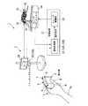
図1に示すように、手術支援装置1は、マスタマニピュレータ(操作入力部)2、スレーブマニピュレータ14(動作部)、表示装置20、及び制御装置21を備える。
マスタマニピュレータ2は、操作者Opの動きに応じてスレーブマニピュレータ14を動作させるために設けられており、操作者Opによって把持される被検出体3と、被検出体3を検出する検出装置10とを備える。また、本実施形態では、マスタマニピュレータ2と、制御装置21における変換処理部22とによって、スレーブマニピュレータ14を動作させるための操作指令を発する操作入力部が構成されている。As shown in FIG. 1, the surgery support apparatus 1 includes a master manipulator (operation input unit) 2, a slave manipulator 14 (operation unit), a
The master manipulator 2 is provided for operating the
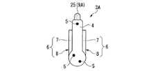
図1及び図2に示すように、被検出体3は、操作者Opが被検出体3を把持してマスタマニピュレータ2に対する入力操作をするために設けられている。被検出体3は、本体部4と、本体部4に対して移動可能に連結された操作部6とを備える。 As shown in FIGS. 1 and 2, the detected
本体部4は、外面に第一マーカー5が設けられた部材である。本体部4に設けられた第一マーカー5は、本体部4の外面において互いに離間する3箇所に設けられている。第一マーカー5は、本体部4の外面に例えば印刷によって設けられている。
第一マーカー5は、本体部4に対して位置決めされて配置されている。このため、第一マーカー5の位置及び姿勢は、本体部4の位置及び姿勢に対応している。さらに、3つの第一マーカー5は、各第一マーカー5と頂点とする三角形の三辺の長さが互いに異なるように配置されている。これにより、各第一マーカー5の相対位置関係により本体部4の姿勢を一意に特定することができる。
また、本実施形態では、後述する撮影部11に設けられたカメラのうちの一台に全ての第一マーカー5が撮影されるようにする目的で、本体部4の外面における平面状の部分若しくは極緩やかな曲面状の部分に第一マーカー5が配されている。The
The
Further, in the present embodiment, for the purpose of photographing all the
また、あるマーカーが操作中に遮蔽された場合に対応できるよう、3つ以上のマーカーが余分に設けられていてもよい。あるマーカーが遮蔽された場合は、余分に設けられたうちの別のマーカーを用いて位置・姿勢を求める。
なお、3つ若しくはそれ以上の第一マーカー5が一枚のシート上に配され当該シートが本体部4の外面に貼り付けられていてもよい。Further, three or more markers may be provided in an extra manner so as to cope with a case where a certain marker is shielded during operation. When a certain marker is shielded, the position / orientation is obtained using another marker provided in extra.
Note that three or more
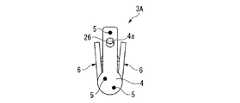
図2及び図3に示すように、操作部6は、スレーブマニピュレータ14に設けられた術具16を操作するために設けられており、図1に示すように操作者Opによって操作される。本実施形態では、操作部6は、術具16である把持鉗子の処置部18に配された一対の鉗子片17を開閉動作させるために設けられている(図4参照)。操作部6は、本体部4の外面から突出する一対の棒状部7を有している。各棒状部7の一端側には、本体部4に対して棒状部7を回動可能に支持する支点部8が設けられている。各棒状部7の他端には、操作部6に対する操作に対応して状態が変化する第二マーカー9が設けられている。本実施形態では、第二マーカー9は、操作部6に対する操作に対応して、操作部6と一体に移動される。また、本実施形態では、第二マーカー9は、配置位置以外は第一マーカー5と同一の構成を有している。
一対の棒状部7は、本体部4を間に挟むように対向配置されている。各支点部8を回動軸として各棒状部7が回動することにより、操作部6は、術具16に設けられた一対の鉗子片17の動作に対応した開閉動作をすることができるようになっている。操作部6の開閉機構としては、例えばリンク機構6aと、棒状部7が開くようにリンク機構6aを付勢する付勢部材6bとを有する。As shown in FIGS. 2 and 3, the
The pair of rod-
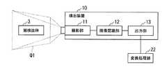
図5は、手術支援装置における検出装置の構成を説明するための模式図である。図6及び図7は、手術支援装置における被検出体の検出方法を説明するための説明図である。
図5に示すように、検出装置10は、撮影部11と、画像認識部12と、出力部13とを備える。FIG. 5 is a schematic diagram for explaining a configuration of a detection device in the surgery support apparatus. 6 and 7 are explanatory diagrams for explaining a detection method of the detection target in the surgery support apparatus.
As illustrated in FIG. 5, the
撮影部11は、被検出体3が使用者によって使用されているときの被検出体3を撮影する装置である。撮影部11の撮影視野は、手術支援装置1の使用時において使用者によって被検出体3が移動される空間(以下、「作業空間Q1」と称する。)の全体を撮影することができるように設定されている。また、撮影部11は、作業空間Q1に対して所定の一方向から撮影をする第一のカメラと、上記所定の一方向とは別の方向から撮影をする第二のカメラとを少なくとも備えている。これにより、撮影部11は、作業空間Q1内に位置する被検出体3に対して、互いにアングルが異なる少なくとも2画像を同時に撮影することができる。なお、撮影部11は、3以上のカメラを有していてもよい。また、撮影部11は、被検出体3とカメラとの間に操作者Op自身若しくは他の障害物が入り込んだ場合を想定して予備のカメラを備えた冗長構成を有していてもよい。撮影部11は、撮影された画像を、画像認識部12へと出力する。 The
画像認識部12は、撮影された画像から、画像認識処理により第一マーカー5及び第二マーカー9を区別して認識する。本実施形態では、第一マーカー5と第二マーカー9とは配置位置のみが異なっており、画像認識部12では、第一マーカー5と第二マーカー9の相対位置関係のみに基づいて第一マーカー5と第二マーカー9とを識別する。例えば、第一マーカー5と第二マーカー9との相対位置関係のパターンが画像認識部12に記憶されており、撮影部11から入力された画像と当該パターンとを照合することによって作業空間Q1内における第一マーカー5及び第二マーカー9の座標を取得する。また、本実施形態では、第一マーカー5は本体部4における位置関係が固定状態であるので、第一マーカー5を頂点とする三角形を先に検出し(図6参照)、当該三角形の外側に位置するマーカーを第二マーカー9として検出することができる。その他、画像認識処理としては、公知の手段を適宜採用することができる。 The
出力部13は、画像認識部12において取得された座標を、制御装置21の変換処理部22へと座標情報として出力する。本実施形態において、出力部13から出力される座標情報は、被検出体3の位置及び姿勢を変換処理部22が特定するための情報(第一情報)、及び操作部6への操作入力状態を変換処理部22が特定するための情報(第二情報)となっている。出力部13からは、被検出体3が作業空間Q1内で移動しているか否かに関わらず、所定の発信タイミングに従って座標情報が出力される。 The
図1に示すように、スレーブマニピュレータ14は、内視鏡装置15及び術具16(以下、「術具等」と総称する場合がある。)が取り付けられたスレーブアーム19と、術具等及びスレーブアーム19を動作させるアクチュエータ(不図示)とを備える。スレーブマニピュレータ14に設けられた各アクチュエータは、制御装置21から出力される駆動信号に従って動作する。 As shown in FIG. 1, the
図1に示すように、スレーブマニピュレータ14に設けられた内視鏡装置15は、処置対象物や術具16の画像を取得して表示装置20へと出力する。 As shown in FIG. 1, the
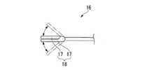
術具16は、内視鏡装置15の視野内で処置対象物に対して処置を行う目的で設けられている。術具16の種類は特に限定されることはなく、処置の内容に応じて公知の術具を適宜採用することができる。また、術具16は、スレーブマニピュレータ14に取り付け可能な術具には限られず、スレーブマニピュレータ14と協動する術具であってもよい。 The
本実施形態では、術具16の例として、開閉動作可能な一対の鉗子片17を有する把持鉗子を示す(図4参照)。把持鉗子は、所定の回動軸によって一対の鉗子片17が互いに連結されており、上記一対の鉗子片17によって処置部18が構成されている。処置部18の位置及び姿勢は、把持鉗子若しくはスレーブアーム19に設けられた位置姿勢検出手段によって検出される。当該位置姿勢検出手段によって検出された処置部18の位置及び姿勢は、制御装置21へ出力されたり、制御装置21によって参照されたりする。
位置姿勢検出手段とは、たとえば、スレーブアーム19の各関節軸に設けられたエンコーダなどである。これらの関節変位量から、運動学を解くことで該位置姿勢を算出することができる。In this embodiment, a grasping forceps having a pair of
The position / orientation detection means is, for example, an encoder provided on each joint axis of the
図1に示すように、表示装置20は、マスタマニピュレータ2の検出装置10と同じ土台に取り付けられており、操作者Opの前方に設置されている。表示装置20は、内視鏡装置15によって取得された画像を表示する表示パネルを有している。表示パネルは、液晶パネルや有機ELパネル等を適宜選択して採用することができる。また、表示パネルは、立体視可能な画像を表示するパネルであってもよい。立体視可能な画像を表示するパネルは、専用のメガネにより右目用と左目用の画像が分離可能な構成や、裸眼立体視が可能な構成などを採用することができる。 As shown in FIG. 1, the
制御装置21は、検出装置10と接続された変換処理部22と、変換処理部22と接続されているとともにスレーブマニピュレータ14の各アクチュエータに接続されたスレーブ駆動部23とを備える。 The
変換処理部22は、スレーブマニピュレータ14に設けられた位置姿勢検出手段によって術具16及びスレーブアーム19の位置及び姿勢並びに術具16に設けられた処置部18の状態を示すスレーブマニピュレータ14のトラッキング情報を取得する。スレーブマニピュレータ14のトラッキング情報は、変換処理部22において、例えば直交座標系などによって規定された所定の三次元空間内における術具16及びスレーブアーム19の位置及び姿勢並びに処置部18の位置及び姿勢として記憶される。 The
また、変換処理部22には、検出装置10から出力された被検出体3の座標情報が入力される。被検出体3の座標情報は上記所定の発信タイミングに従って変換処理部22に入力され、変換処理部22における被検出体3のトラッキング情報として変換処理部22に取得される。 Further, the coordinate information of the detected
変換処理部22は、被検出体3のトラッキング情報とスレーブマニピュレータ14のトラッキング情報とのそれぞれの座標系を整合させる座標系変換機能を有している。また、変換処理部22は、被検出体3のトラッキング情報における縮尺とスレーブマニピュレータ14のトラッキング情報における縮尺とを整合させる縮尺変換機能を有している。座標変換機能及び縮尺変換機能により、表示装置20を見て被検出体3を動かす操作者Opの動作を、スレーブマニピュレータ14の動作に適切に変換することができる。また、変換処理部22には、各第二マーカー9間の距離と、各鉗子片17の先端の距離との間の対応関係が記憶されている。 The
変換処理部22は、スレーブマニピュレータ14を動作させるための操作指令をスレーブ駆動部23に対して出力する。変換処理部22が発する操作指令は、例えば、スレーブマニピュレータ14に設けられた複数のアクチュエータのうち動作させるアクチュエータを特定する信号と、当該アクチュエータの動作量を特定する信号とを含む。 The
スレーブ駆動部23は、変換処理部22からの操作指令に対応して、スレーブマニピュレータ14の各アクチュエータを駆動させる。 The
次に、手術支援装置1の制御方法及び動作について説明する。
手術支援装置1の使用時には、操作者Opは、被検出体3を把持し、例えば操作部6に指を掛ける(図1参照)。操作者Opが本体部4を移動させると、本体部4に設けられた第一マーカー5は本体部4と一体に移動する(図2及び図3参照)。このとき、第一マーカー5は、検出装置10に設けられた撮影部11によって撮影されている。さらに、操作部6に設けられた第二マーカー9は、操作部6と一体に移動する。このとき、第二マーカー9は、検出装置10に設けられた撮影部11によって撮影されている。Next, a control method and operation of the surgery support apparatus 1 will be described.
When using the surgery support apparatus 1, the operator Op holds the detected
本実施形態では、検出装置10に予め記憶された第一マーカー5及び第二マーカー9の配置パターンに基づいて、第一マーカー5と第二マーカー9とを識別する。そして、検出装置10では、術者が表示装置20に向いて表示装置20を見ている姿勢における前後、上下、及び左右を座標軸とする直交座標系による三次元空間(すなわち上記作業空間)における第一マーカー5の姿勢及び位置並びに第二マーカー9の姿勢及び位置を検出する。ここで、第一マーカー5の姿勢及び位置は、本体部4の姿勢及び位置に対応し、第二マーカー9の姿勢及び位置は、操作部6の姿勢及び位置に対応する。検出装置10では、検出装置10において規定された上記三次元空間内における各第一マーカー5及び各第二マーカー9の座標情報を変換処理部22へと出力する。 In the present embodiment, the
変換処理部22では、検出装置10から出力された座標情報(被検出体3のトラッキング情報)とスレーブマニピュレータ14から取得したスレーブマニピュレータ14のトラッキング情報とを比較し、処置部18の位置及び姿勢の制御と、処置部18に設けられた鉗子片17の開閉制御を行なう。 In the
まず、処置部18の位置及び姿勢の制御について説明する。
変換処理部22は、3つの第一マーカー5の座標情報に基づいて、作業空間内における本体部4の位置及び姿勢を認識する。さらに、変換処理部22において認識された本体部4の位置及び姿勢と、スレーブマニピュレータ14のトラッキング情報との関係が所定の対応関係と異なっている場合には、変換処理部22は、スレーブ駆動部23を動作させ、所定の対応関係を満たすようにスレーブアーム19及び術具16を移動させる。このとき、変換処理部22は、作業空間の座標系とスレーブマニピュレータ14の座標系とを整合させるための座標変換と縮尺変換を行い、変換後の情報を用いて操作指令を生成してスレーブ駆動部23へと出力する。First, control of the position and posture of the
The
次に、鉗子片17の開閉制御について説明する。
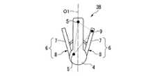
変換処理部22では、3つの第一マーカー5が共に存する仮想平面と平行な仮想平面に沿って測ったときの各第二マーカー9間の距離dを算出する(図7参照)。本実施形態では、各第二マーカー9の座標が検出装置10により算出されており、変換処理部22は、当該座標を用いて各第二マーカー9の距離を算出する。さらに、変換処理部22に入力された各第二マーカー9間の距離とスレーブマニピュレータ14のトラッキング情報における鉗子片17の先端の距離との関係が所定の対応関係と異なっている場合には、変換処理部22は、スレーブ駆動部23を動作させ、所定の対応関係を満たすように鉗子片17の開度を変更する。これにより、本体部4に対する操作部6の移動が、スレーブマニピュレータ14の鉗子片17の開閉動作として伝達される。Next, opening / closing control of the
The
このように、変換処理部22は、被検出体3のトラッキング情報とスレーブマニピュレータ14のトラッキング情報とを比較し、各トラッキング情報が互いに異なっている場合には、スレーブマニピュレータ14のトラッキング情報が被検出体3のトラッキング情報と一致するように操作指令を発する。変換処理部22が発する操作指令により、スレーブ駆動部23は、被検出体3の位置及び姿勢並びに操作部6への操作入力状態に対応した状態となるようにスレーブアーム19及び術具16を移動させる。
その結果、スレーブマニピュレータ14は、被検出体3の動作に追従して動作する。As described above, the
As a result, the
以上説明したように、本実施形態の手術支援装置1によれば、被検出体3の本体部4に配される、事前に決められた配置関係から変化しない第一マーカー5により被検出体3の位置及び姿勢を検出し、被検出体3の操作部6に配される、事前に決められた配置関係から変化する第二マーカー9により操作部6に対する操作入力状態を別のマーカー(第一マーカー5及び第二マーカー9)として分類して検出することができるので、簡易な構成で高精度な遠隔操作入力をすることができる。 As described above, according to the surgery support apparatus 1 of the present embodiment, the detected
ここで、被検出体3の位置及び姿勢を検出するために使用される第一マーカー5はいずれも本体部4に対して位置決めされているので位置及び姿勢の検出がしやすい。さらに、本体部4に対する位置関係が既知である第一マーカー5を元にして第二マーカー9を識別することができるので、第一マーカー5と第二マーカー9とにおける配置位置以外の構成が同一であってよいから、構成を簡素にすることができる。 Here, since all of the
また、位置及び姿勢を検出するためのマーカーと操作入力状態を検出するためのマーカーとが別々に設けられているので、誤検出が少ない。 Further, since the marker for detecting the position and orientation and the marker for detecting the operation input state are provided separately, there are few false detections.
(変形例1−1)
次に、上述の第1実施形態の変形例について説明する。図8及び図9は、手術支援装置における被検出体の検出方法を説明するための説明図である。
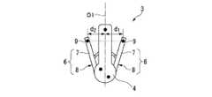
本変形例では、変換処理部22における第二マーカー9の距離の算出方法が異なっている。
変換処理部22では、第一マーカー5を用いた本体部4の姿勢の検出結果から、本体部4の中心軸O1を規定する(図8参照)。続いて、当該中心軸O1から第二マーカー9までの距離d1、d2を、各第二マーカー9に対して個別に算出する(図9参照)。これにより、本変形例では、変換処理部22は、本体部4に対する第二マーカー9の位置の変化に基づいて操作部6への操作入力状態を算出できる。
本変形例では、各操作部6に設けられた第二マーカー9の一方が撮影部11に撮影されていない状態であっても、他方が撮影部11に撮影されていれば上述の実施形態と同様の検出結果が得られる。(Modification 1-1)
Next, a modification of the above-described first embodiment will be described. 8 and 9 are explanatory diagrams for explaining a detection method of the detection target in the surgery support apparatus.
In this modification, the calculation method of the distance of the
The
In the present modification, even if one of the
(変形例1−2)
次に、上述の第1実施形態の他の変形例について説明する。
本変形例では、上述の第1実施形態で説明した第一マーカー5と第二マーカー9とが配置位置以外の少なくとも一の事項において相違する例を示す。
例えば、第一マーカー5と第二マーカー9とが互いに異なる色とされている。また、撮影部11は、少なくとも第一マーカー5の色と第二マーカー9の色とを区別して取得できるようになっている。さらに、検出装置10は、第一マーカー5の座標と第二マーカー9の座標とをそれぞれ区別して変換処理部22へと出力する。
本変形例の構成によれば、色に基づいて第一マーカー5と第二マーカー9とを区別することができるので、第一マーカー5と第二マーカー9との相対位置関係から第一マーカー5と第二マーカー9を識別するための計算を変換処理部22が行う必要がないので、計算量が少ない。また、第一マーカー5と第二マーカー9とが近づいた場合に、二つのマーカーを誤認識する確率を減らすことができる。(Modification 1-2)
Next, another modification of the above-described first embodiment will be described.
In the present modification, an example is shown in which the
For example, the
According to the configuration of the present modification, the
なお、本変形例では色に基づいて第一マーカー5と第二マーカー9とを区別する例を示したが、色以外にも、寸法、形状、模様、あるいは光の反射率を異ならせることによっても同様の効果を奏することができる。
また、第一マーカー5と第二マーカー9とを、互いに発光周期若しくは光量が異なる光源27によって構成することもできる。
このように、第一マーカー5と第二マーカー9との相違点に基づいて第一マーカー5と第二マーカー9とをそれぞれ識別することができる。In addition, in this modification, although the example which distinguishes the
Moreover, the
As described above, the
(変形例1−3)
次に、上述の第1実施形態のさらに他の変形例について説明する。図10は、本変形例の手術支援装置における一部の構成を示す模式図である。
本変形例では、上述の変形例2に示したように互いに色、寸法、形状、模様、光の反射率、発光周期若しくは光量が異なる第一マーカー5及び第二マーカー9を有している。さらに、図10に示すように、検出装置10は、第一マーカー5を検出するための第一検出部10aと第二マーカー9を検出するための第二検出部10bとを備える。(Modification 1-3)
Next, still another modification of the above-described first embodiment will be described. FIG. 10 is a schematic diagram illustrating a part of the configuration of the surgery support apparatus according to the present modification.
In the present modification, the
本変形例によれば、本体部4の位置及び姿勢を検出するための検出系と、操作部6の操作状態を検出するための検出系が互いに独立しているので、操作部6の操作を容易に検出することができ、検出精度を高めることができる。 According to the present modification, the detection system for detecting the position and orientation of the
なお、本変形例における各マーカーと各検出部との組み合わせは、適合する好適な組み合わせを適宜採用することができる。例えば、2種類のカメラから成る検出装置として、赤外線センサと色識別カメラをそれぞれ検出部として備えた検出装置、認識可能波長が互いに異なるカメラを検出部として備えた検出装置、広角カメラとズームカメラをそれぞれ検出部として備えた検出装置、あるいは第一マーカー5と第二マーカー9との発光周期に対応させて撮影周期をずらして撮影するカメラを検出部として備えた検出装置などを構成することができる。
また、上述の2種類のカメラから成る検出装置でなく、2種類のセンサ系から成る検出装置としても良い。例えば、次に示すようなもの挙げられる。第一マーカー5を反射マーカーとし、それを検出する光学センサを検出部とし、第二マーカー9を磁気コイルとして、それを検出する磁気センサを検出部として備えた検出装置としても良い。また、第二マーカー9を超音波発生器として、それを検出する超音波センサを検出部として備えた検出装置としても良い。さらに、第二マーカー9を熱源として、それを検出する温度センサを検出部とした検出装置としても良い。
また、2種類のセンサ系から成る検出装置としてしているが、1種類のセンサ系から成る検出装置としてしても良い。例えば、第一マーカー5及び第二マーカー9を周波数の違う信号発生器とし、それぞれを検出する一つの信号検出部を備えた検出装置としても良い。尚、信号としては、例えば、光の周波数、電波の周波数、超音波の周波数等が挙げられる。In addition, the suitable combination which can match can be employ | adopted suitably for the combination of each marker and each detection part in this modification. For example, as a detection device composed of two types of cameras, a detection device provided with an infrared sensor and a color identification camera as a detection unit, a detection device provided with cameras having different recognizable wavelengths as detection units, a wide-angle camera and a zoom camera, respectively. A detection device provided as a detection unit, or a detection device provided with a camera as a detection unit that shoots with a shooting period shifted corresponding to the light emission cycle of the
Moreover, it is good also as a detection apparatus which consists of two types of sensor systems instead of the detection apparatus which consists of the above-mentioned two types of camera. Examples include the following. The
Moreover, although it is set as the detection apparatus which consists of two types of sensor systems, it is good also as a detection apparatus which consists of one type of sensor system. For example, the
(第2実施形態)
次に、本発明の第2実施形態の手術支援装置1について説明する。なお、以下に説明する各実施形態において、上述の第1実施形態と同様の構成要素には同一符号を付して重複する説明を省略する。
図11ないし図13は、本実施形態の手術支援装置に設けられた被検出体を示す平面図である。
図1及び図11に示すように、本実施形態の手術支援装置1は、マスタマニピュレータ2に設けられた被検出体3及び検出装置10に代えて被検出体3A及び検出装置10Aを備え、制御装置21に設けられた変換処理部22に代えて変換処理部22Aを備える点が異なっている。(Second Embodiment)
Next, the surgery assistance apparatus 1 of 2nd Embodiment of this invention is demonstrated. Note that, in each embodiment described below, the same components as those in the first embodiment described above are denoted by the same reference numerals, and redundant description is omitted.
FIG. 11 to FIG. 13 are plan views showing detected bodies provided in the surgery support apparatus of this embodiment.
As shown in FIG.1 and FIG.11, the surgery assistance apparatus 1 of this embodiment is equipped with the to-
被検出体3Aは、第二マーカー9に代えて、第二マーカー9Aを備える。
図11ないし図13に示すように、第二マーカー9Aは、操作部6の回動動作によって本体部4から突没する直動棒25を有している。直動棒25は、支点部8周りの回転移動を直線移動に変換するリンク等の変換機構を介して操作部6の棒状部7に連結されている。本実施形態では、一対の棒状部7を支点部8回りに回転移動させて操作部6を閉じると直動棒25が本体部4から突出し、一対の棒状部7を支点部8回りに回転移動させて操作部6を開くと直動棒25が本体部4内に没する。これにより、操作部6に開度に対応して直動棒25の本体部4からの突出長さが変化する。The detected
As shown in FIGS. 11 to 13, the
検出装置10Aは、上記第1実施形態と同様に第一マーカー5についての検出をする。さらに、検出装置10Aは、上記第1実施形態で説明した第二マーカー9の検出に代えて、第二マーカー9Aの検出をする。第二マーカー9Aの検出は、直動棒25が本体部4から突出された部分の表面積の大きさを検出することにより行われる。このとき、被検出体3と撮影部11のカメラとの距離によって画像上における直動棒25の表面積は異なるので、作業空間Q1内における被検出体3の位置情報を用いて直動棒25の表面積を、画像上大きさから実際の大きさへと補正する。検出装置10Aは、第一マーカー5を用いて算出した本体部4に関する座標情報と、第二マーカー9Aを用いて算出した直動棒25の表面積を、変換処理部22Aへと出力する。 10 A of detection apparatuses detect about the
変換処理部22Aでは、検出装置10Aにより算出された直動棒25の表面積を用いて、一対の鉗子片17の開度を制御する。例えば、直動棒25が本体部4内に完全に入り込んでいる場合には、直動棒25が本体部4から突出する面積がゼロであり、この場合を、一対の鉗子片17が全開状態である場合に対応させておく。さらに、直動棒25が本体部4から突出する面積が所定の面積を超える場合を、一対の鉗子片17が全閉状態である場合に対応させておく。例えば、上記所定の面積は、操作部6を全閉状態としたときに直動棒25が本体部4から突出する面積とすることができる。 In the
本実施形態では、変換処理部22Aは、第二マーカー9Aに設けられた直動棒25の表面積の変化に基づいて、一対の鉗子片17の開度を制御するための操作指令をスレーブ駆動部23へ出力する。本実施形態の構成であっても、上記第1実施形態と同様に被検出体3に対する操作に連動させてスレーブマニピュレータ14を動作させることができる。
なお、直動棒25の表面積の変化に基づいて制御する方法ではなく、直動棒25の先端と末端の距離の変化量に基づいて鉗子片17の開度を制御してもよい。In the present embodiment, the
Note that the opening degree of the
(変形例2−1)
次に、上述の第2実施形態の変形例について説明する。図14ないし図16は、本変形例における被検出体を示す平面図である。
図14ないし図16に示すように、本変形例では、本体部4から突没する直動棒25に代えて、本体部4に窓4aが形成され、窓4a内で移動することにより露出面積が代わる直動部材26が本体部4内に設けられている点が異なっている。
本変形例では、窓4aの開口面積に対する直動部材26の露出面積を用いて一対の鉗子片17の開度を指示することができる。(Modification 2-1)
Next, a modification of the above-described second embodiment will be described. 14 to 16 are plan views showing the detection target in the present modification.
As shown in FIGS. 14 to 16, in this modification, a
In this modification, the opening degree of the pair of
(変形例2−2)
次に、上述の第2実施形態の他の変形例について説明する。図17及び図18は、本変形例における被検出体を示す平面図である。
図17及び図18に示すように、本変形例では、第二マーカー9Aにおいて、直動棒25に代えて、操作部6の棒状部7の開閉により発光状態が変化する光源27が設けられている点が異なっている。
第二マーカー9Aに設けられた光源27は、棒状部7の開閉により、光量、点滅周期、色その他少なくとも一状態が変化する。
なお、光源27の光量を変化させる方法の別の例としては、上述の変形例2−1において説明した直動棒25に代えて、直動棒25と同様に直線移動するカバーと、本体部4に設けられ当該カバーによって覆われる光源とを備えてもよい。この場合における光源自体は、光量や発光周期は一定であってもよい。このような構成の場合、操作部6に対する操作によって上記カバーが移動し、光源がカバーに覆われる面積が変わるので、検出装置10に到達する光量が変わる。(Modification 2-2)
Next, another modification of the above-described second embodiment will be described. 17 and 18 are plan views showing the detection target in the present modification.
As shown in FIGS. 17 and 18, in the present modification, in the
The
In addition, as another example of the method of changing the light quantity of the
(第3実施形態)
次に、本発明の第3実施形態の手術支援装置について説明する。図19及び図20は、本実施形態の手術支援装置に設けられた被検出体を示す平面図である。
手術支援装置1は、第1実施形態で説明した被検出体3に代えて設けられた被検出体3Bと、第1実施形態で説明した変換処理部22に代えて設けられた変換処理部22Bとを備えている点が異なっている。
被検出体3Bは、第1実施形態と同様の本体部4及び操作部6を有しており、配置状態が第1実施形態と異なる第一マーカー5が本体部4に配されている。(Third embodiment)
Next, the surgery assistance apparatus of 3rd Embodiment of this invention is demonstrated. 19 and 20 are plan views showing the detection target provided in the surgery support apparatus of the present embodiment.
The surgery support apparatus 1 includes a
The to-
第一マーカー5は、本体部4の外面の一箇所に配されており、第二マーカー9は、操作部6における一対の棒状部7のそれぞれに第1実施形態と同様に1つずつ配されている。また、第一マーカー5から各第二マーカー9までの距離は互いに等しく、各第二マーカー9の間の距離は第一マーカー5と第二マーカー9との距離よりも短い。これにより、操作部6をどのような開度としても第一マーカー5及び第二マーカー9により構成される三点は二等辺三角形の頂点となる。 The
検出装置10では、作業空間Q1内における第一マーカー5と第二マーカー9とのそれぞれの座標を変換処理部22Bへと出力する。 In the
変換処理部22Bでは、第一マーカー5と第二マーカー9とによって構成される上記二等辺三角形の位置に基づいて被検出体3の位置を算出する。また変換処理部22Bでは、第一マーカー5と第二マーカー9とによって構成される上記二等辺三角形の向きに基づいて被検出体3の姿勢を算出する。さらに、各第二マーカー9の間の距離は、第一マーカー5と第二マーカー9とによって構成される上記二等辺三角形の底辺の長さとして他の辺と区別して認識することができる。 In the
このように、本実施形態では、本体部4に配された1つのマーカー(第一マーカー5)と、操作部6の棒状部7にそれぞれ1つずつ配されたマーカー(第二マーカー9)との計3つのマーカーによって、被検出体3の位置及び姿勢並びに操作部6の操作状態を検出することができる。このため、上述の第1実施形態に示した被検出体3よりもマーカーの数が少なくてよい。このため、マーカーを配するスペースが小さくて済むので、被検出体3を小型化しやすい。 Thus, in the present embodiment, one marker (first marker 5) arranged on the
(変形例3−1)
次に、上述の実施形態の変形例について説明する。図21及び図22は、本変形例の被検出体を示す平面図である。
図21及び図22に示すように、本変形例では、本体部4に第一マーカー5が2つ配され、操作部6における棒状部7の一方に第二マーカー9が1つ配されている点が異なっている。
本体部4に配された2つの第一マーカー5は、互いに離間する二箇所に位置している。2つの第一マーカー5の距離は一定である。(Modification 3-1)
Next, a modification of the above embodiment will be described. 21 and 22 are plan views showing the detection target of the present modification.
As shown in FIGS. 21 and 22, in the present modification, two
The two
本変形例では、第一マーカー5と第二マーカー9とによる三点を用いて被検出体3Bの位置と姿勢とをそれぞれ検出することができる。さらに、被検出体3Bの位置及び姿勢から、本体の中心軸O1を算出することができる。さらに中心軸O1に対する第二マーカー9の距離を上記変形例1−1と同様に算出することができる。
このように、本変形例においても、被検出体3Bの位置及び姿勢並びに操作部6の操作入力状態を第一マーカー5及び第二マーカー9を用いて検出することができる。In the present modification, the position and posture of the
Thus, also in the present modification, the position and orientation of the
以上、本発明の実施形態について図面を参照して詳述したが、具体的な構成はこの実施形態に限られるものではなく、本発明の要旨を逸脱しない範囲の設計変更等も含まれる。
また、上述の各実施形態及び各変形例において示した構成要素は適宜に組み合わせて構成することが可能である。As mentioned above, although embodiment of this invention was explained in full detail with reference to drawings, the concrete structure is not restricted to this embodiment, The design change etc. of the range which does not deviate from the summary of this invention are included.
In addition, the constituent elements shown in the above-described embodiments and modifications can be combined as appropriate.
1 手術支援装置
2 マスタマニピュレータ(操作入力部)
3、3A、3B 被検出体
4 本体部
4a 窓
5 第一マーカー
6 操作部
7 棒状部
8 支点部
9、9A 第二マーカー
10、10A 検出装置
11 撮影部
12 画像認識部
13 出力部
14 スレーブマニピュレータ
15 内視鏡装置
16 術具
17 鉗子片
18 処置部
19 スレーブアーム
20 表示装置
21 制御装置
22、22A、22B 変換処理部
23 駆動部
Op 操作者1 Surgery support device 2 Master manipulator (operation input unit)
3, 3A, 3B Detected
Claims (8)
Translated fromJapanese前記操作入力部は、
前記操作者に把持される被検出体と、
前記被検出体を検出する検出装置と、
を備え、
前記被検出体は、
前記検出装置により検出される3つの第一マーカーが設けられた本体部と、
前記本体部に設けられ前記操作者に操作される操作部と、
前記本体部と前記操作部との少なくとも何れかに設けられ前記操作部に対する操作に対応して状態が変化する第二マーカーと、
を有し、
前記第一マーカーは、三辺の長さが互いに異なる三角形の頂点となるように互いに離間して前記本体部に配置され、
前記検出装置は、少なくとも前記第一マーカーを用いて前記被検出体の位置及び姿勢を特定可能な情報を算出し、且つ少なくとも前記第二マーカーを用いて前記操作部への操作入力状態を特定可能な情報を算出し、
前記操作入力部は、前記検出装置により算出された結果に基づいて、前記術具を移動させるための指令を前記操作指令として前記動作部へ出力することにより、前記被検出体の位置及び姿勢並びに前記操作入力状態に応じて前記術具の動作を制御する
ことを特徴とする手術支援装置。An operation support device including an operation input unit that issues an operation command based on an input from an operator, and an operation unit that operates a surgical instrument based on the operation command,
The operation input unit includes:
An object to be detected held by the operator;
A detection device for detecting the detected object;
With
The detected object is:
A main body provided withthree first markers detected by the detection device;
An operation unit provided in the main body unit and operated by the operator;
A second marker that is provided in at least one of the main body part and the operation part and whose state changes in response to an operation on the operation part;
Have
The first marker is arranged in the main body part so as to be spaced apart from each other such that the lengths of the three sides are different from each other.
The detection device can calculate information capable of specifying the position and orientation of the detected object using at least the first marker, and can specify an operation input state to the operation unit using at least the second marker. To calculate
The operation input unit outputs a command for moving the surgical tool to the operation unit as the operation command based on a result calculated by the detection device, thereby allowing the position and posture of the detected body and An operation support apparatus for controlling an operation of the surgical instrument according to the operation input state.
前記操作部は前記本体部に対して移動可能に連結されており、
前記第二マーカーは前記操作部に設けられ、
前記検出装置は、少なくとも前記第一マーカーを用いて前記本体部の位置及び姿勢を算出し、且つ前記第二マーカーの位置に基づいて前記操作部への操作入力状態を算出する
ことを特徴とする手術支援装置。The surgery support apparatus according to claim 1,
The operation unit is movably connected to the main body unit,
The second marker is provided in the operation unit,
The detection device calculates the position and orientation of the main body using at least the first marker, and calculates an operation input state to the operation unit based on the position of the second marker. Surgery support device.
前記操作部は前記本体部に対して開閉動作可能であることを特徴とする手術支援装置。The surgery support apparatus according to claim 2,
The operation support device is capable of opening and closing with respect to the main body.
前記第一マーカーと前記第二マーカーとは、配置位置以外の少なくとも一つの事項において相違し、
前記検出装置は、前記第一マーカーと前記第二マーカーとの相違点に基づいて前記第一マーカーと前記第二マーカーとを識別する
ことを特徴とする手術支援装置。The surgical operation support apparatus according to any one of claims 1 to 3,
The first marker and the second marker differ in at least one matter other than the arrangement position,
The operation support apparatus, wherein the detection device identifies the first marker and the second marker based on a difference between the first marker and the second marker.
前記第一マーカーと前記第二マーカーとは前記操作入力部における配置位置のみが異なり、
前記検出装置は、前記第一マーカー及び前記第二マーカーの前記操作入力部上での相対位置関係のみに基づいて前記第一マーカーと前記第二マーカーとを識別する
ことを特徴とする手術支援装置。The surgical operation support apparatus according to any one of claims 1 to 3,
The first marker and the second marker are different only in the arrangement position in the operation input unit,
The operation support apparatus, wherein the detection device identifies the first marker and the second marker based only on a relative positional relationship between the first marker and the second marker on the operation input unit. .
前記検出装置は、前記第一マーカーと前記第二マーカーとの両方を用いて前記本体部の位置及び姿勢並びに前記操作入力状態を算出する
ことを特徴とする手術支援装置。The surgical operation support device according to claim 3,
The detection apparatus calculates the position and posture of the main body and the operation input state using both the first marker and the second marker.
前記被検出体の前記第一マーカーおよび前記第二マーカーを検出し、
前記検出された少なくとも前記第一マーカーを用いて前記被検出体の位置及び姿勢を特定可能な第一情報を算出し、且つ前記検出された少なくとも前記第二マーカーを用いて前記操作部への操作入力状態を特定可能な第二情報を算出し、
前記第一情報と前記第二情報とを用いて前記手術支援装置に設けられた術具の動作を制御する
ことを特徴とする手術支援装置の制御方法。Surgery support using a detected body having a main body portionwith three first markers thatare spaced apart from each other so that the three sides of the triangles have different vertexes, and an operation portion with a second marker A method for controlling a surgery support device for controlling a device, comprising:
Detecting the first marker and the second marker of the detected object;
First information that can specify the position and orientation of the detected object is calculated using the detected at least first marker, and the operation unit is operated using the detected at least second marker Calculate the second information that can identify the input state,
A method for controlling a surgery support apparatus, comprising: controlling an operation of a surgical tool provided in the surgery support apparatus using the first information and the second information.
Priority Applications (5)
| Application Number | Priority Date | Filing Date | Title |
|---|---|---|---|
| JP2012040011AJP6005950B2 (en) | 2011-08-04 | 2012-02-27 | Surgery support apparatus and control method thereof |
| EP12819447.9AEP2739231B1 (en) | 2011-08-04 | 2012-07-30 | Operation support device |
| CN201280038440.5ACN103717171B (en) | 2011-08-04 | 2012-07-30 | Surgical support device and control method thereof |
| PCT/JP2012/069927WO2013018912A1 (en) | 2011-08-04 | 2012-07-30 | Operation support device and control method thereof |
| US14/169,742US9632577B2 (en) | 2011-08-04 | 2014-01-31 | Operation support device and control method thereof |
Applications Claiming Priority (4)
| Application Number | Priority Date | Filing Date | Title |
|---|---|---|---|
| US201161515203P | 2011-08-04 | 2011-08-04 | |
| US61/515,203 | 2011-08-04 | ||
| JP2012040011AJP6005950B2 (en) | 2011-08-04 | 2012-02-27 | Surgery support apparatus and control method thereof |
| PCT/JP2012/069927WO2013018912A1 (en) | 2011-08-04 | 2012-07-30 | Operation support device and control method thereof |
Publications (2)
| Publication Number | Publication Date |
|---|---|
| JP2013034835A JP2013034835A (en) | 2013-02-21 |
| JP6005950B2true JP6005950B2 (en) | 2016-10-12 |
Family
ID=52579593
Family Applications (1)
| Application Number | Title | Priority Date | Filing Date |
|---|---|---|---|
| JP2012040011AActiveJP6005950B2 (en) | 2011-08-04 | 2012-02-27 | Surgery support apparatus and control method thereof |
Country Status (5)
| Country | Link |
|---|---|
| US (1) | US9632577B2 (en) |
| EP (1) | EP2739231B1 (en) |
| JP (1) | JP6005950B2 (en) |
| CN (1) | CN103717171B (en) |
| WO (1) | WO2013018912A1 (en) |
Families Citing this family (37)
| Publication number | Priority date | Publication date | Assignee | Title |
|---|---|---|---|---|
| JP6323974B2 (en)* | 2012-05-18 | 2018-05-16 | オリンパス株式会社 | Surgery support device |
| JP6053358B2 (en)* | 2012-07-03 | 2016-12-27 | オリンパス株式会社 | Surgery support device |
| EP3708105B1 (en) | 2013-08-15 | 2022-02-09 | Intuitive Surgical Operations, Inc. | Preloaded surgical instrument interface |
| CN108784838B (en) | 2013-08-15 | 2021-06-08 | 直观外科手术操作公司 | Instrument sterile adapter drive interface |
| CN109602495B (en) | 2013-08-15 | 2021-05-11 | 直观外科手术操作公司 | Instrument sterile adapter drive features |
| US10016244B2 (en)* | 2013-08-15 | 2018-07-10 | Intuitive Surgical Operations, Inc. | Robotic instrument driven element |
| JP2016016238A (en)* | 2014-07-10 | 2016-02-01 | オリンパス株式会社 | manipulator |
| DE102014115600A1 (en) | 2014-10-27 | 2016-04-28 | Karl Storz Gmbh & Co. Kg | Surgical instrument with a manual control device |
| JP6766062B2 (en) | 2015-03-17 | 2020-10-07 | インテュイティブ サージカル オペレーションズ, インコーポレイテッド | Systems and methods for on-screen identification of instruments in remote-controlled medical systems |
| WO2016151667A1 (en)* | 2015-03-20 | 2016-09-29 | 富士機械製造株式会社 | Teaching device and method for generating control information |
| WO2016151668A1 (en)* | 2015-03-20 | 2016-09-29 | 富士機械製造株式会社 | Teaching device and method for generating control information |
| DE102015109371A1 (en)* | 2015-06-12 | 2016-12-15 | avateramedical GmBH | Apparatus and method for robotic surgery |
| US9872738B2 (en)* | 2016-01-06 | 2018-01-23 | Ethicon Endo-Surgery, Llc | Methods, systems, and devices for control of surgical tools in a robotic surgical system |
| WO2017145340A1 (en)* | 2016-02-25 | 2017-08-31 | オリンパス株式会社 | Manipulator system and operating method therefor |
| US10922836B2 (en)* | 2016-11-15 | 2021-02-16 | Carl Zeiss Industrielle Messtechnik Gmbh | Method and system for determining a 3D position of an object in space |
| WO2018109851A1 (en) | 2016-12-14 | 2018-06-21 | オリンパス株式会社 | Medical manipulator system |
| US11633246B2 (en)* | 2016-12-15 | 2023-04-25 | Intuitive Surgical Operations, Inc. | Actuated grips for controller |
| WO2018179323A1 (en) | 2017-03-31 | 2018-10-04 | オリンパス株式会社 | Manipulator |
| CN111386085B (en) | 2017-10-02 | 2023-12-26 | 直观外科手术操作公司 | End effector force feedback to master controller |
| IT201800005468A1 (en)* | 2018-05-17 | 2019-11-17 | Robotic system for surgery, particularly microsurgery | |
| WO2019220407A1 (en)* | 2018-05-17 | 2019-11-21 | Medical Microinstruments S.p.A. | Master controller assembly for a robotic surgery system, particularly for microsurgery |
| US11135031B2 (en) | 2018-06-15 | 2021-10-05 | Verb Surgical Inc. | User interface device having grip linkages |
| US11135030B2 (en) | 2018-06-15 | 2021-10-05 | Verb Surgical Inc. | User interface device having finger clutch |
| JP2021529014A (en)* | 2018-06-15 | 2021-10-28 | バーブ サージカル インコーポレイテッドVerb Surgical Inc. | User interface device with grip link |
| WO2020042148A1 (en)* | 2018-08-31 | 2020-03-05 | 天津大学 | Magnetic navigation sensing-based main operating hand and system of minimally invasive surgical robot |
| CN109316239B (en)* | 2018-08-31 | 2020-08-04 | 天津大学 | Main operator and system of minimally invasive surgical robot based on magnetic navigation sensing |
| CA3116287A1 (en) | 2018-10-15 | 2020-04-23 | Mazor Robotics Ltd. | Versatile multi-arm robotic surgical system |
| DE102018218475B4 (en)* | 2018-10-29 | 2022-03-10 | Carl Zeiss Optotechnik GmbH | Tracking system and optical measuring system for determining at least one spatial position and orientation of at least one measurement object |
| EP3685785A1 (en)* | 2019-01-22 | 2020-07-29 | Stryker European Holdings I, LLC | Tracker for a surgical navigation system |
| DE102019118012B3 (en)* | 2019-07-03 | 2020-09-17 | Günther Battenberg | Method and device for controlling a robot system by means of human movement |
| US11696807B2 (en)* | 2020-03-17 | 2023-07-11 | Verb Surgical Inc. | Drop detection of ungrounded master controller for a surgical robot |
| CN112057172B (en)* | 2020-09-10 | 2022-02-11 | 苏州大学 | Minimally invasive surgery robot |
| US11786315B2 (en)* | 2020-09-18 | 2023-10-17 | Verb Surgical Inc. | Surgical robotic system having grip-dependent control |
| US12274525B2 (en) | 2020-09-29 | 2025-04-15 | Mazor Robotics Ltd. | Systems and methods for tracking anatomical motion |
| IT202100003488A1 (en)* | 2021-02-16 | 2022-08-16 | Medical Microinstruments Inc | "METHOD FOR VERIFYING THE INTEGRITY OF A MASTER DEVICE OF A MASTER-SLAVE TYPE ROBOTIC SYSTEM FOR MEDICAL OR SURGICAL TELEOPERATION" |
| CN118021442B (en)* | 2024-04-10 | 2024-06-14 | 苏州国科康成医疗科技有限公司 | Virtual reality interaction equipment for operation simulation and operation simulation method |
| CN119632692B (en)* | 2025-02-13 | 2025-06-06 | 杭州迪视医疗生物科技有限公司 | Master-slave control method of operation system, electronic equipment and storage medium |
Family Cites Families (247)
| Publication number | Priority date | Publication date | Assignee | Title |
|---|---|---|---|---|
| US3139990A (en) | 1961-12-11 | 1964-07-07 | Central Res Lab Inc | Rugged-duty master-slave manipulator |
| US3923166A (en) | 1973-10-11 | 1975-12-02 | Nasa | Remote manipulator system |
| CA1276710C (en) | 1983-11-30 | 1990-11-20 | Kazuo Asakawa | Robot force controlling system |
| US4672281A (en) | 1985-10-10 | 1987-06-09 | Durstin Machine & Manufacturing, Inc. | Control for electric motor that drives a robotic appendage |
| JPH0789293B2 (en) | 1986-07-23 | 1995-09-27 | 松下電器産業株式会社 | Arm control device |
| SE462645B (en) | 1987-03-31 | 1990-08-06 | Asea Ab | DEVICE FOR INDUSTRIAL ROBOTS WITH REGARD TO TOOLS |
| JPS6434688A (en) | 1987-07-29 | 1989-02-06 | Kubota Ltd | Master/slave manipulator |
| JPH0796182B2 (en) | 1988-03-16 | 1995-10-18 | ニッタ株式会社 | A device that eliminates the effects of the weight of the tool |
| JPH01271185A (en) | 1988-04-20 | 1989-10-30 | Fujitsu Ltd | Remote robot manipulating system |
| JP3088004B2 (en) | 1989-04-28 | 2000-09-18 | 株式会社東芝 | Operation command device |
| JP2610956B2 (en) | 1988-09-05 | 1997-05-14 | 株式会社日立製作所 | Master-slave manipulator |
| JPH0741560B2 (en) | 1989-11-16 | 1995-05-10 | 工業技術院長 | Master / slave robot control method |
| US5214969A (en) | 1991-02-19 | 1993-06-01 | Philip Morris Incorporated | Automatic testing of a plurality of smoking articles |
| JPH0596477A (en) | 1991-10-03 | 1993-04-20 | Mitsubishi Heavy Ind Ltd | Control method for master and slave manipulators |
| US6963792B1 (en) | 1992-01-21 | 2005-11-08 | Sri International | Surgical method |
| US5631973A (en) | 1994-05-05 | 1997-05-20 | Sri International | Method for telemanipulation with telepresence |
| JPH05329784A (en) | 1992-05-28 | 1993-12-14 | Yaskawa Electric Corp | Master / slave robot control method |
| US5762458A (en) | 1996-02-20 | 1998-06-09 | Computer Motion, Inc. | Method and apparatus for performing minimally invasive cardiac procedures |
| US5760530A (en) | 1992-12-22 | 1998-06-02 | The United States Of America As Represented By The Secretary Of The Air Force | Piezoelectric tactile sensor |
| JP2610094B2 (en) | 1993-05-13 | 1997-05-14 | 株式会社明電舎 | Control device for industrial manipulator |
| ATE209875T1 (en) | 1993-07-21 | 2001-12-15 | Charles H Klieman | SURGICAL INSTRUMENT FOR ENDOSCOPIC AND GENERAL OPERATIONS |
| US5656903A (en) | 1993-10-01 | 1997-08-12 | The Ohio State University Research Foundation | Master-slave position and motion control system |
| US5876325A (en) | 1993-11-02 | 1999-03-02 | Olympus Optical Co., Ltd. | Surgical manipulation system |
| JP3339953B2 (en) | 1993-12-29 | 2002-10-28 | オリンパス光学工業株式会社 | Medical master-slave manipulator |
| JPH07241300A (en) | 1994-03-04 | 1995-09-19 | Olympus Optical Co Ltd | Holder of medical treatment appliance |
| JPH07246578A (en)* | 1994-03-11 | 1995-09-26 | Yaskawa Electric Corp | Master hand device |
| DE4412605B4 (en) | 1994-04-13 | 2005-10-20 | Zeiss Carl | Method for operating a stereotactic adapter |
| US5643286A (en) | 1994-06-24 | 1997-07-01 | Cytotherapeutics, Inc. | Microdrive for use in stereotactic surgery |
| JP2991403B2 (en) | 1994-08-29 | 1999-12-20 | 株式会社アイチコーポレーション | Manipulator gripper control device |
| US5836869A (en) | 1994-12-13 | 1998-11-17 | Olympus Optical Co., Ltd. | Image tracking endoscope system |
| US5632432A (en) | 1994-12-19 | 1997-05-27 | Ethicon Endo-Surgery, Inc. | Surgical instrument |
| US5603723A (en) | 1995-01-11 | 1997-02-18 | United States Surgical Corporation | Surgical instrument configured to be disassembled for cleaning |
| JPH08215204A (en) | 1995-02-08 | 1996-08-27 | Olympus Optical Co Ltd | Medical manipulator |
| JPH08243080A (en) | 1995-03-07 | 1996-09-24 | Olympus Optical Co Ltd | Endoscope cleaning and disinfecting apparatus |
| US5814038A (en) | 1995-06-07 | 1998-09-29 | Sri International | Surgical manipulator for a telerobotic system |
| US5649956A (en) | 1995-06-07 | 1997-07-22 | Sri International | System and method for releasably holding a surgical instrument |
| US5784542A (en) | 1995-09-07 | 1998-07-21 | California Institute Of Technology | Decoupled six degree-of-freedom teleoperated robot system |
| US5712543A (en) | 1995-10-31 | 1998-01-27 | Smith & Nephew Endoscopy Inc. | Magnetic switching element for controlling a surgical device |
| US5871493A (en) | 1995-10-31 | 1999-02-16 | Smith & Nephew Endoscopy Inc. | Surgical instrument handpiece and system |
| US6063095A (en) | 1996-02-20 | 2000-05-16 | Computer Motion, Inc. | Method and apparatus for performing minimally invasive surgical procedures |
| US6699177B1 (en) | 1996-02-20 | 2004-03-02 | Computer Motion, Inc. | Method and apparatus for performing minimally invasive surgical procedures |
| US6436107B1 (en) | 1996-02-20 | 2002-08-20 | Computer Motion, Inc. | Method and apparatus for performing minimally invasive surgical procedures |
| JP4176126B2 (en) | 1996-02-20 | 2008-11-05 | コンピュータ・モーション・インコーポレーテッド | Method and apparatus for performing cardiac surgery with minimal invasion |
| US5855583A (en) | 1996-02-20 | 1999-01-05 | Computer Motion, Inc. | Method and apparatus for performing minimally invasive cardiac procedures |
| US5792135A (en) | 1996-05-20 | 1998-08-11 | Intuitive Surgical, Inc. | Articulated surgical instrument for performing minimally invasive surgery with enhanced dexterity and sensitivity |
| US6364888B1 (en) | 1996-09-09 | 2002-04-02 | Intuitive Surgical, Inc. | Alignment of master and slave in a minimally invasive surgical apparatus |
| JPH10128538A (en) | 1996-10-29 | 1998-05-19 | Hitachi Constr Mach Co Ltd | Welding robot and its sensor adapter |
| US6132441A (en) | 1996-11-22 | 2000-10-17 | Computer Motion, Inc. | Rigidly-linked articulating wrist with decoupled motion transmission |
| US9050119B2 (en) | 2005-12-20 | 2015-06-09 | Intuitive Surgical Operations, Inc. | Cable tensioning in a robotic surgical system |
| US6132368A (en) | 1996-12-12 | 2000-10-17 | Intuitive Surgical, Inc. | Multi-component telepresence system and method |
| US7699855B2 (en) | 1996-12-12 | 2010-04-20 | Intuitive Surgical Operations, Inc. | Sterile surgical adaptor |
| US6331181B1 (en) | 1998-12-08 | 2001-12-18 | Intuitive Surgical, Inc. | Surgical robotic tools, data architecture, and use |
| US7666191B2 (en) | 1996-12-12 | 2010-02-23 | Intuitive Surgical, Inc. | Robotic surgical system with sterile surgical adaptor |
| US8206406B2 (en) | 1996-12-12 | 2012-06-26 | Intuitive Surgical Operations, Inc. | Disposable sterile surgical adaptor |
| US6039748A (en) | 1997-08-05 | 2000-03-21 | Femrx, Inc. | Disposable laparoscopic morcellator |
| EP2362286B1 (en) | 1997-09-19 | 2015-09-02 | Massachusetts Institute Of Technology | Robotic apparatus |
| US20080177285A1 (en) | 1998-02-24 | 2008-07-24 | Hansen Medical, Inc. | Surgical instrument |
| JPH11300662A (en) | 1998-04-27 | 1999-11-02 | Yokogawa Electric Corp | Micro tweezers |
| JP4129313B2 (en) | 1998-05-19 | 2008-08-06 | オリンパス株式会社 | Medical system control device |
| WO2000007503A1 (en) | 1998-08-04 | 2000-02-17 | Intuitive Surgical, Inc. | Manipulator positioning linkage for robotic surgery |
| US6082797A (en) | 1998-11-02 | 2000-07-04 | Fanuc Robotics North America, Inc. | Gripping tool assembly |
| US6852107B2 (en) | 2002-01-16 | 2005-02-08 | Computer Motion, Inc. | Minimally invasive surgical training using robotics and tele-collaboration |
| US8600551B2 (en) | 1998-11-20 | 2013-12-03 | Intuitive Surgical Operations, Inc. | Medical robotic system with operatively couplable simulator unit for surgeon training |
| US6659939B2 (en) | 1998-11-20 | 2003-12-09 | Intuitive Surgical, Inc. | Cooperative minimally invasive telesurgical system |
| US6459926B1 (en) | 1998-11-20 | 2002-10-01 | Intuitive Surgical, Inc. | Repositioning and reorientation of master/slave relationship in minimally invasive telesurgery |
| US6602185B1 (en) | 1999-02-18 | 2003-08-05 | Olympus Optical Co., Ltd. | Remote surgery support system |
| US6594552B1 (en) | 1999-04-07 | 2003-07-15 | Intuitive Surgical, Inc. | Grip strength with tactile feedback for robotic surgery |
| JP4354042B2 (en) | 1999-04-30 | 2009-10-28 | オリンパス株式会社 | Medical manipulator device |
| JP3608448B2 (en) | 1999-08-31 | 2005-01-12 | 株式会社日立製作所 | Treatment device |
| DE50014373D1 (en) | 1999-09-09 | 2007-07-12 | Tuebingen Scient Medical Gmbh | SURGICAL INSTRUMENT FOR MINIMALLY INVASIVE INTERVENTIONS |
| US8004229B2 (en) | 2005-05-19 | 2011-08-23 | Intuitive Surgical Operations, Inc. | Software center and highly configurable robotic systems for surgery and other uses |
| US7594912B2 (en) | 2004-09-30 | 2009-09-29 | Intuitive Surgical, Inc. | Offset remote center manipulator for robotic surgery |
| JP2001087281A (en) | 1999-09-20 | 2001-04-03 | Olympus Optical Co Ltd | Multifunctional manipulator |
| US6206903B1 (en) | 1999-10-08 | 2001-03-27 | Intuitive Surgical, Inc. | Surgical tool with mechanical advantage |
| JP3188953B2 (en) | 1999-10-13 | 2001-07-16 | 経済産業省産業技術総合研究所長 | Power assist device and control method thereof |
| US6666876B2 (en) | 2000-02-24 | 2003-12-23 | Hitachi, Ltd. | Forceps and manipulator with using thereof |
| JP2001309920A (en) | 2000-02-24 | 2001-11-06 | Hitachi Ltd | Forceps and manipulator using the same |
| JP3613551B2 (en) | 2000-03-31 | 2005-01-26 | 株式会社東芝 | Medical manipulator |
| US8888688B2 (en) | 2000-04-03 | 2014-11-18 | Intuitive Surgical Operations, Inc. | Connector device for a controllable instrument |
| US20010055062A1 (en) | 2000-04-20 | 2001-12-27 | Keiji Shioda | Operation microscope |
| JP4716545B2 (en) | 2000-06-28 | 2011-07-06 | オリンパス株式会社 | Surgical microscope equipment |
| US6645196B1 (en) | 2000-06-16 | 2003-11-11 | Intuitive Surgical, Inc. | Guided tool change |
| US6746443B1 (en) | 2000-07-27 | 2004-06-08 | Intuitive Surgical Inc. | Roll-pitch-roll surgical tool |
| JP2002059380A (en)* | 2000-08-22 | 2002-02-26 | Olympus Optical Co Ltd | Master-slave device |
| JP4014792B2 (en)* | 2000-09-29 | 2007-11-28 | 株式会社東芝 | manipulator |
| US6840938B1 (en) | 2000-12-29 | 2005-01-11 | Intuitive Surgical, Inc. | Bipolar cauterizing instrument |
| EP2298220B1 (en) | 2001-02-15 | 2016-06-08 | Hansen Medical, Inc. | Flexible instrument |
| US20030135204A1 (en) | 2001-02-15 | 2003-07-17 | Endo Via Medical, Inc. | Robotically controlled medical instrument with a flexible section |
| US7699835B2 (en) | 2001-02-15 | 2010-04-20 | Hansen Medical, Inc. | Robotically controlled surgical instruments |
| JP3660887B2 (en) | 2001-03-19 | 2005-06-15 | 株式会社日立製作所 | Surgery support device |
| US6994708B2 (en) | 2001-04-19 | 2006-02-07 | Intuitive Surgical | Robotic tool with monopolar electro-surgical scissors |
| US6783524B2 (en) | 2001-04-19 | 2004-08-31 | Intuitive Surgical, Inc. | Robotic surgical tool with ultrasound cauterizing and cutting instrument |
| US20040243147A1 (en) | 2001-07-03 | 2004-12-02 | Lipow Kenneth I. | Surgical robot and robotic controller |
| JP2003024336A (en) | 2001-07-16 | 2003-01-28 | Hitachi Ltd | Operation instrument |
| JP3926119B2 (en) | 2001-08-10 | 2007-06-06 | 株式会社東芝 | Medical manipulator |
| US6676684B1 (en) | 2001-09-04 | 2004-01-13 | Intuitive Surgical, Inc. | Roll-pitch-roll-yaw surgical tool |
| JP4832679B2 (en) | 2001-09-11 | 2011-12-07 | オリンパス株式会社 | Microscope system |
| US6587750B2 (en) | 2001-09-25 | 2003-07-01 | Intuitive Surgical, Inc. | Removable infinite roll master grip handle and touch sensor for robotic surgery |
| US6839612B2 (en) | 2001-12-07 | 2005-01-04 | Institute Surgical, Inc. | Microwrist system for surgical procedures |
| JP4098535B2 (en) | 2002-02-28 | 2008-06-11 | オリンパス株式会社 | Medical stereoscopic display |
| JP3766805B2 (en) | 2002-03-15 | 2006-04-19 | 株式会社日立製作所 | Surgery support device |
| JP4073249B2 (en) | 2002-05-17 | 2008-04-09 | オリンパス株式会社 | Surgery system |
| JP3712693B2 (en) | 2002-05-21 | 2005-11-02 | 株式会社東芝 | Medical manipulator |
| US7331967B2 (en) | 2002-09-09 | 2008-02-19 | Hansen Medical, Inc. | Surgical instrument coupling mechanism |
| JP3680050B2 (en) | 2002-09-18 | 2005-08-10 | 株式会社東芝 | Medical manipulator and control method thereof |
| JP4118114B2 (en) | 2002-09-25 | 2008-07-16 | アルプス電気株式会社 | Force sense input device |
| JP3912251B2 (en) | 2002-10-02 | 2007-05-09 | 株式会社日立製作所 | manipulator |
| US7443115B2 (en) | 2002-10-29 | 2008-10-28 | Matsushita Electric Industrial Co., Ltd. | Apparatus and method for robot handling control |
| JP3686947B2 (en) | 2002-12-09 | 2005-08-24 | 国立大学法人 東京大学 | High-rigid forceps tip structure for active forceps and active forceps including the same |
| JP3805310B2 (en) | 2003-01-30 | 2006-08-02 | ファナック株式会社 | Work take-out device |
| WO2004106009A1 (en) | 2003-06-02 | 2004-12-09 | Matsushita Electric Industrial Co., Ltd. | Article operating system and method, and article managing system and method |
| US7476237B2 (en) | 2003-02-27 | 2009-01-13 | Olympus Corporation | Surgical instrument |
| US7295893B2 (en) | 2003-03-31 | 2007-11-13 | Kabushiki Kaisha Toshiba | Manipulator and its control apparatus and method |
| DE10324844A1 (en) | 2003-04-01 | 2004-12-23 | Tuebingen Scientific Surgical Products Gmbh | Surgical instrument with instrument handle and zero point adjustment |
| US20050033117A1 (en) | 2003-06-02 | 2005-02-10 | Olympus Corporation | Object observation system and method of controlling object observation system |
| JP2005013715A (en) | 2003-06-05 | 2005-01-20 | Olympus Corp | Observation system |
| US9002518B2 (en) | 2003-06-30 | 2015-04-07 | Intuitive Surgical Operations, Inc. | Maximum torque driving of robotic surgical tools in robotic surgical systems |
| DE10357105B3 (en) | 2003-12-06 | 2005-04-07 | Richard Wolf Gmbh | Medical instrument for medical applications comprises an insert and a handle detachedly connected to each other |
| JP4472361B2 (en) | 2004-01-06 | 2010-06-02 | オリンパス株式会社 | Medical instrument holding device and medical instrument holding system. |
| JP2005261827A (en) | 2004-03-22 | 2005-09-29 | Olympus Corp | Treatment tool for endoscope |
| US7879070B2 (en) | 2004-07-28 | 2011-02-01 | Ethicon Endo-Surgery, Inc. | Electroactive polymer-based actuation mechanism for grasper |
| JP2006061272A (en) | 2004-08-25 | 2006-03-09 | Olympus Corp | Medical instrument holding device |
| US9261172B2 (en) | 2004-09-30 | 2016-02-16 | Intuitive Surgical Operations, Inc. | Multi-ply strap drive trains for surgical robotic arms |
| US20060087746A1 (en) | 2004-10-22 | 2006-04-27 | Kenneth Lipow | Remote augmented motor-sensory interface for surgery |
| US8795195B2 (en) | 2004-11-29 | 2014-08-05 | Senorx, Inc. | Graphical user interface for tissue biopsy system |
| JP2006167867A (en) | 2004-12-16 | 2006-06-29 | Fuji Heavy Ind Ltd | Remote control device |
| JP4528136B2 (en) | 2005-01-11 | 2010-08-18 | 株式会社日立製作所 | Surgical device |
| US7837674B2 (en) | 2005-01-24 | 2010-11-23 | Intuitive Surgical Operations, Inc. | Compact counter balance for robotic surgical systems |
| US7559450B2 (en) | 2005-02-18 | 2009-07-14 | Ethicon Endo-Surgery, Inc. | Surgical instrument incorporating a fluid transfer controlled articulation mechanism |
| US7654431B2 (en) | 2005-02-18 | 2010-02-02 | Ethicon Endo-Surgery, Inc. | Surgical instrument with guided laterally moving articulation member |
| US8496647B2 (en) | 2007-12-18 | 2013-07-30 | Intuitive Surgical Operations, Inc. | Ribbed force sensor |
| JP5160025B2 (en) | 2005-04-14 | 2013-03-13 | オリンパスメディカルシステムズ株式会社 | Surgery system |
| EP1876942A4 (en) | 2005-04-18 | 2009-04-08 | M S T Medical Surgery Technolo | Means and methods of improving laparoscopic surgery |
| US9492240B2 (en) | 2009-06-16 | 2016-11-15 | Intuitive Surgical Operations, Inc. | Virtual measurement tool for minimally invasive surgery |
| US8108072B2 (en) | 2007-09-30 | 2012-01-31 | Intuitive Surgical Operations, Inc. | Methods and systems for robotic instrument tool tracking with adaptive fusion of kinematics information and image information |
| US8147503B2 (en) | 2007-09-30 | 2012-04-03 | Intuitive Surgical Operations Inc. | Methods of locating and tracking robotic instruments in robotic surgical systems |
| US8073528B2 (en) | 2007-09-30 | 2011-12-06 | Intuitive Surgical Operations, Inc. | Tool tracking systems, methods and computer products for image guided surgery |
| JP2006321027A (en) | 2005-05-20 | 2006-11-30 | Hitachi Ltd | Master / slave manipulator system and its operation input device |
| US7717312B2 (en) | 2005-06-03 | 2010-05-18 | Tyco Healthcare Group Lp | Surgical instruments employing sensors |
| US8398541B2 (en) | 2006-06-06 | 2013-03-19 | Intuitive Surgical Operations, Inc. | Interactive user interfaces for robotic minimally invasive surgical systems |
| JP4015161B2 (en) | 2005-06-13 | 2007-11-28 | 川崎重工業株式会社 | Industrial robot controller |
| JP4488312B2 (en) | 2005-07-08 | 2010-06-23 | オリンパス株式会社 | Medical manipulator system |
| JP2007029274A (en) | 2005-07-25 | 2007-02-08 | Hitachi Ltd | Surgical device |
| US7959050B2 (en) | 2005-07-26 | 2011-06-14 | Ethicon Endo-Surgery, Inc | Electrically self-powered surgical instrument with manual release |
| JP2007038315A (en) | 2005-08-01 | 2007-02-15 | Toyota Motor Corp | Operation device and operation control method and program therefor |
| JP2007098507A (en) | 2005-10-04 | 2007-04-19 | Nagoya Institute Of Technology | Work assistance device |
| WO2007047782A2 (en) | 2005-10-20 | 2007-04-26 | Intuitive Surgical, Inc | Auxiliary image display and manipulation on a computer display in a medical robotic system |
| US8190238B2 (en) | 2005-12-09 | 2012-05-29 | Hansen Medical, Inc. | Robotic catheter system and methods |
| US9241767B2 (en) | 2005-12-20 | 2016-01-26 | Intuitive Surgical Operations, Inc. | Method for handling an operator command exceeding a medical device state limitation in a medical robotic system |
| US7453227B2 (en) | 2005-12-20 | 2008-11-18 | Intuitive Surgical, Inc. | Medical robotic system with sliding mode control |
| US7819859B2 (en) | 2005-12-20 | 2010-10-26 | Intuitive Surgical Operations, Inc. | Control system for reducing internally generated frictional and inertial resistance to manual positioning of a surgical manipulator |
| JP5043414B2 (en) | 2005-12-20 | 2012-10-10 | インテュイティブ サージカル インコーポレイテッド | Aseptic surgical adapter |
| KR101337278B1 (en) | 2005-12-20 | 2013-12-09 | 인튜어티브 서지컬 인코포레이티드 | Instrument interface of a robotic surgical system |
| US8628518B2 (en) | 2005-12-30 | 2014-01-14 | Intuitive Surgical Operations, Inc. | Wireless force sensor on a distal portion of a surgical instrument and method |
| US7907166B2 (en) | 2005-12-30 | 2011-03-15 | Intuitive Surgical Operations, Inc. | Stereo telestration for robotic surgery |
| US9173550B2 (en) | 2006-01-13 | 2015-11-03 | Olympus Corporation | Medical apparatus |
| US8439828B2 (en) | 2006-01-13 | 2013-05-14 | Olympus Medical Systems Corp. | Treatment endoscope |
| US8617054B2 (en) | 2006-01-13 | 2013-12-31 | Olympus Medical Systems Corp. | Medical treatment endoscope |
| US8092371B2 (en) | 2006-01-13 | 2012-01-10 | Olympus Medical Systems Corp. | Medical treatment endoscope |
| US9289112B2 (en) | 2006-01-13 | 2016-03-22 | Olympus Corporation | Medical treatment endoscope having an operation stick formed to allow a procedure instrument to pass |
| US8021293B2 (en) | 2006-01-13 | 2011-09-20 | Olympus Medical Systems Corp. | Medical treatment endoscope |
| US20070208375A1 (en) | 2006-02-23 | 2007-09-06 | Kouji Nishizawa | Surgical device |
| JP4908020B2 (en) | 2006-03-02 | 2012-04-04 | 本田技研工業株式会社 | Hand control system |
| US9636188B2 (en) | 2006-03-24 | 2017-05-02 | Stryker Corporation | System and method for 3-D tracking of surgical instrument in relation to patient body |
| WO2007138674A1 (en) | 2006-05-30 | 2007-12-06 | Olympus Medical Systems Corp. | Endoscope treatment system |
| JP2008000282A (en) | 2006-06-21 | 2008-01-10 | Olympus Medical Systems Corp | Procedure image recording control system and operation system |
| JP4755047B2 (en) | 2006-08-08 | 2011-08-24 | テルモ株式会社 | Working mechanism and manipulator |
| US7920124B2 (en) | 2006-08-29 | 2011-04-05 | Canon Kabushiki Kaisha | Force sense presentation device, mixed reality system, information processing method, and information processing apparatus |
| US7313464B1 (en) | 2006-09-05 | 2007-12-25 | Adept Technology Inc. | Bin-picking system for randomly positioned objects |
| WO2008038184A2 (en) | 2006-09-25 | 2008-04-03 | Koninklijke Philips Electronics N.V. | Haptic feedback medical scanning methods and systems |
| JP4680164B2 (en) | 2006-10-13 | 2011-05-11 | テルモ株式会社 | manipulator |
| JP5085996B2 (en) | 2006-10-25 | 2012-11-28 | テルモ株式会社 | Manipulator system |
| JP2008104854A (en) | 2006-10-25 | 2008-05-08 | Terumo Corp | Medical manipulator |
| WO2008058039A1 (en) | 2006-11-06 | 2008-05-15 | University Of Florida Research Foundation, Inc. | Devices and methods for utilizing mechanical surgical devices in a virtual environment |
| JP4911701B2 (en)* | 2007-01-19 | 2012-04-04 | 株式会社日立製作所 | Master / slave manipulator system |
| JP4960112B2 (en) | 2007-02-01 | 2012-06-27 | オリンパスメディカルシステムズ株式会社 | Endoscopic surgery device |
| WO2008103383A1 (en) | 2007-02-20 | 2008-08-28 | Gildenberg Philip L | Videotactic and audiotactic assisted surgical methods and procedures |
| JP4930100B2 (en) | 2007-02-27 | 2012-05-09 | ソニー株式会社 | Force / tactile display, force / tactile display control method, and computer program |
| US8700213B2 (en) | 2007-03-01 | 2014-04-15 | Tokyo Institute Of Technology | Maneuvering system having inner force sense presenting function |
| JP4916011B2 (en) | 2007-03-20 | 2012-04-11 | 株式会社日立製作所 | Master / slave manipulator system |
| EP2148629B1 (en) | 2007-04-16 | 2012-06-06 | NeuroArm Surgical, Ltd. | Frame mapping and force feedback methods, devices and systems |
| US20090132088A1 (en) | 2007-04-24 | 2009-05-21 | Tairob Ltd. | Transfer of knowledge from a human skilled worker to an expert machine - the learning process |
| JP5335201B2 (en) | 2007-05-08 | 2013-11-06 | キヤノン株式会社 | Diagnostic imaging equipment |
| US9089256B2 (en) | 2008-06-27 | 2015-07-28 | Intuitive Surgical Operations, Inc. | Medical robotic system providing an auxiliary view including range of motion limitations for articulatable instruments extending out of a distal end of an entry guide |
| US8620473B2 (en) | 2007-06-13 | 2013-12-31 | Intuitive Surgical Operations, Inc. | Medical robotic system with coupled control modes |
| JP5319188B2 (en) | 2007-07-18 | 2013-10-16 | 株式会社東芝 | X-ray diagnostic equipment |
| JP2009028157A (en) | 2007-07-25 | 2009-02-12 | Terumo Corp | Medical manipulator system |
| US20090046146A1 (en) | 2007-08-13 | 2009-02-19 | Jonathan Hoyt | Surgical communication and control system |
| JP2009056164A (en) | 2007-08-31 | 2009-03-19 | Terumo Corp | Medical manipulator system |
| JP5017076B2 (en) | 2007-12-21 | 2012-09-05 | テルモ株式会社 | Manipulator system and manipulator control method |
| US20090171147A1 (en) | 2007-12-31 | 2009-07-02 | Woojin Lee | Surgical instrument |
| EP2240083B8 (en) | 2008-01-10 | 2015-08-19 | Covidien LP | Imaging system for a surgical device |
| US20110046637A1 (en) | 2008-01-14 | 2011-02-24 | The University Of Western Ontario | Sensorized medical instrument |
| JP5154961B2 (en) | 2008-01-29 | 2013-02-27 | テルモ株式会社 | Surgery system |
| US20090204911A1 (en) | 2008-02-12 | 2009-08-13 | Kiyoshi Sekiguchi | Medical support control system |
| US20090193299A1 (en) | 2008-01-29 | 2009-07-30 | Kiyoshi Sekiguchi | Medical support control system |
| JP2009178541A (en) | 2008-01-29 | 2009-08-13 | Olympus Medical Systems Corp | Medical support control system |
| KR100975047B1 (en) | 2008-02-15 | 2010-08-11 | (주)미래컴퍼니 | Coupling Structure of Surgical Instruments |
| JP5210014B2 (en) | 2008-03-24 | 2013-06-12 | テルモ株式会社 | manipulator |
| JP5148335B2 (en) | 2008-03-25 | 2013-02-20 | テルモ株式会社 | Operating jig |
| JP5198118B2 (en) | 2008-03-28 | 2013-05-15 | 富士フイルム株式会社 | Adapter device and ultrasonic inspection system |
| US8155479B2 (en) | 2008-03-28 | 2012-04-10 | Intuitive Surgical Operations Inc. | Automated panning and digital zooming for robotic surgical systems |
| JP2009269127A (en) | 2008-05-08 | 2009-11-19 | Sony Corp | Holding device and method of controlling the same |
| US20090281378A1 (en) | 2008-05-09 | 2009-11-12 | Kazuo Banju | Medical system |
| EP2127604A1 (en) | 2008-05-30 | 2009-12-02 | Nederlandse Organisatie voor toegepast- natuurwetenschappelijk onderzoek TNO | An instrument for minimally invasive surgery |
| WO2009151205A1 (en) | 2008-06-11 | 2009-12-17 | (주)미래컴퍼니 | Instrument of surgical robot arm |
| US8540748B2 (en) | 2008-07-07 | 2013-09-24 | Intuitive Surgical Operations, Inc. | Surgical instrument wrist |
| JP2011527611A (en) | 2008-07-08 | 2011-11-04 | パワー メディカル インターベンションズ, エルエルシー | Surgical attachment for use with robotic surgical systems |
| JP4495252B2 (en) | 2008-07-09 | 2010-06-30 | パナソニック株式会社 | Route risk evaluation device, route risk evaluation method and program |
| US9842192B2 (en) | 2008-07-11 | 2017-12-12 | Intouch Technologies, Inc. | Tele-presence robot system with multi-cast features |
| US20100013767A1 (en) | 2008-07-18 | 2010-01-21 | Wei Gu | Methods for Controlling Computers and Devices |
| JP5139194B2 (en) | 2008-08-06 | 2013-02-06 | オリンパスメディカルシステムズ株式会社 | Active medical device system |
| DE102008041867B4 (en) | 2008-09-08 | 2015-09-10 | Deutsches Zentrum für Luft- und Raumfahrt e.V. | Medical workstation and operating device for manually moving a robot arm |
| JP2010076012A (en) | 2008-09-24 | 2010-04-08 | Toshiba Corp | Manipulator system and control method thereof |
| WO2010042611A1 (en) | 2008-10-07 | 2010-04-15 | The Trustees Of Columbia University In The City Of New York | Systems, devices, and method for providing insertable robotic sensory and manipulation platforms for single port surgery |
| CN102256555B (en) | 2008-12-23 | 2015-09-09 | 马科外科公司 | End effector with release actuator |
| KR101038417B1 (en) | 2009-02-11 | 2011-06-01 | 주식회사 이턴 | Surgical Robot System and Its Control Method |
| US8918207B2 (en) | 2009-03-09 | 2014-12-23 | Intuitive Surgical Operations, Inc. | Operator input device for a robotic surgical system |
| US8423182B2 (en) | 2009-03-09 | 2013-04-16 | Intuitive Surgical Operations, Inc. | Adaptable integrated energy control system for electrosurgical tools in robotic surgical systems |
| US8120301B2 (en) | 2009-03-09 | 2012-02-21 | Intuitive Surgical Operations, Inc. | Ergonomic surgeon control console in robotic surgical systems |
| EP2305144B1 (en) | 2009-03-24 | 2012-10-31 | Olympus Medical Systems Corp. | Robot system for endoscope treatment |
| WO2010126127A1 (en) | 2009-04-30 | 2010-11-04 | テルモ株式会社 | Medical manipulator |
| US9155592B2 (en) | 2009-06-16 | 2015-10-13 | Intuitive Surgical Operations, Inc. | Virtual measurement tool for minimally invasive surgery |
| US8423186B2 (en) | 2009-06-30 | 2013-04-16 | Intuitive Surgical Operations, Inc. | Ratcheting for master alignment of a teleoperated minimally-invasive surgical instrument |
| CN102292194B (en) | 2009-08-21 | 2015-03-04 | 松下电器产业株式会社 | Robot arm control device and control method, assembly robot, robot arm control program, and robot arm control integrated circuit |
| WO2011025786A1 (en) | 2009-08-24 | 2011-03-03 | Board Of Regents | Automated needle insertion mechanism |
| US8888789B2 (en) | 2009-09-23 | 2014-11-18 | Intuitive Surgical Operations, Inc. | Curved cannula surgical system control |
| US20110118708A1 (en) | 2009-11-13 | 2011-05-19 | Intuitive Surgical Operations, Inc. | Double universal joint |
| US8935003B2 (en)* | 2010-09-21 | 2015-01-13 | Intuitive Surgical Operations | Method and system for hand presence detection in a minimally invasive surgical system |
| US8543240B2 (en) | 2009-11-13 | 2013-09-24 | Intuitive Surgical Operations, Inc. | Master finger tracking device and method of use in a minimally invasive surgical system |
| US8521331B2 (en) | 2009-11-13 | 2013-08-27 | Intuitive Surgical Operations, Inc. | Patient-side surgeon interface for a minimally invasive, teleoperated surgical instrument |
| US9542001B2 (en)* | 2010-01-14 | 2017-01-10 | Brainlab Ag | Controlling a surgical navigation system |
| WO2011116332A2 (en) | 2010-03-18 | 2011-09-22 | SPI Surgical, Inc. | Surgical cockpit comprising multisensory and multimodal interfaces for robotic surgery and methods related thereto |
| JP2011206213A (en) | 2010-03-29 | 2011-10-20 | Terumo Corp | Medical manipulator |
| EP2377477B1 (en) | 2010-04-14 | 2012-05-30 | Tuebingen Scientific Medical GmbH | Surgical instrument with elastically moveable instrument head |
| KR101661728B1 (en) | 2010-05-11 | 2016-10-04 | 삼성전자주식회사 | User's input apparatus and electronic device including the user's input apparatus |
| JP5726441B2 (en) | 2010-05-18 | 2015-06-03 | オリンパス株式会社 | manipulator |
| US8956341B2 (en) | 2010-06-10 | 2015-02-17 | Carefusion 2200, Inc. | Surgical device with reusable handle |
| JP5590983B2 (en) | 2010-06-15 | 2014-09-17 | オリンパスメディカルシステムズ株式会社 | Medical instrument holding device |
| WO2012029227A1 (en) | 2010-08-31 | 2012-03-08 | パナソニック株式会社 | Controller and control method for master-slave robot, master-slave robot, control program, and integrated electronic circuit |
| JP5829390B2 (en)* | 2010-09-07 | 2015-12-09 | ソニー株式会社 | Information processing apparatus and information processing method |
| US20120071752A1 (en) | 2010-09-17 | 2012-03-22 | Sewell Christopher M | User interface and method for operating a robotic medical system |
| JP5835906B2 (en) | 2010-09-30 | 2015-12-24 | オリンパス株式会社 | Bending joint mechanism, surgical instrument having the bending joint mechanism, and manipulator having the bending joint mechanism |
| US9510895B2 (en) | 2010-11-05 | 2016-12-06 | Ethicon Endo-Surgery, Llc | Surgical instrument with modular shaft and end effector |
| JP6106594B2 (en)* | 2010-11-11 | 2017-04-05 | ザ・ジョンズ・ホプキンス・ユニバーシティ | Human-machine linkage robot system |
| US9241766B2 (en) | 2010-12-22 | 2016-01-26 | Intuitive Surgical Operations, Inc. | Alternate instrument removal |
| KR101800189B1 (en) | 2012-04-30 | 2017-11-23 | 삼성전자주식회사 | Apparatus and method for controlling power of surgical robot |
- 2012
- 2012-02-27JPJP2012040011Apatent/JP6005950B2/enactiveActive
- 2012-07-30CNCN201280038440.5Apatent/CN103717171B/enactiveActive
- 2012-07-30WOPCT/JP2012/069927patent/WO2013018912A1/enactiveApplication Filing
- 2012-07-30EPEP12819447.9Apatent/EP2739231B1/enactiveActive
- 2014
- 2014-01-31USUS14/169,742patent/US9632577B2/enactiveActive
Also Published As
| Publication number | Publication date |
|---|---|
| US9632577B2 (en) | 2017-04-25 |
| US20140148820A1 (en) | 2014-05-29 |
| EP2739231B1 (en) | 2019-09-04 |
| JP2013034835A (en) | 2013-02-21 |
| EP2739231A4 (en) | 2015-03-18 |
| WO2013018912A1 (en) | 2013-02-07 |
| CN103717171A (en) | 2014-04-09 |
| EP2739231A1 (en) | 2014-06-11 |
| CN103717171B (en) | 2016-10-19 |
Similar Documents
| Publication | Publication Date | Title |
|---|---|---|
| JP6005950B2 (en) | Surgery support apparatus and control method thereof | |
| US11806101B2 (en) | Hand controller for robotic surgery system | |
| US20250009441A1 (en) | Systems And Methods For Surgical Navigation | |
| US11534246B2 (en) | User input device for use in robotic surgery | |
| JP7376569B2 (en) | System and method for tracking the position of robotically operated surgical instruments | |
| US9186796B2 (en) | Master input device and master-slave manipulator | |
| JP5904676B2 (en) | Apparatus and method for robust calibration between machine vision system and robot | |
| CN106535806B (en) | The quantitative three-dimensional imaging of surgical scene from multiport visual angle | |
| CN108366833A (en) | Operation information processing equipment and method | |
| WO2019146201A1 (en) | Information processing device, information processing method, and information processing system | |
| KR20130027006A (en) | Method and apparatus for hand gesture control in a minimally invasive surgical system | |
| CN105188590A (en) | Collision avoidance during controlled movement of an image capture device and an actuatable device movable arm | |
| US11576736B2 (en) | Hand controller for robotic surgery system | |
| JP2024175057A (en) | Medical 3D image measuring device and medical image matching system | |
| US20230092980A1 (en) | Surgical robotic system setup | |
| PL223072B1 (en) | Surgical robot control system for the minimally invasive surgery |
Legal Events
| Date | Code | Title | Description |
|---|---|---|---|
| A621 | Written request for application examination | Free format text:JAPANESE INTERMEDIATE CODE: A621 Effective date:20150220 | |
| A131 | Notification of reasons for refusal | Free format text:JAPANESE INTERMEDIATE CODE: A131 Effective date:20160126 | |
| A521 | Request for written amendment filed | Free format text:JAPANESE INTERMEDIATE CODE: A523 Effective date:20160323 | |
| A521 | Request for written amendment filed | Free format text:JAPANESE INTERMEDIATE CODE: A821 Effective date:20160324 | |
| TRDD | Decision of grant or rejection written | ||
| A01 | Written decision to grant a patent or to grant a registration (utility model) | Free format text:JAPANESE INTERMEDIATE CODE: A01 Effective date:20160823 | |
| A61 | First payment of annual fees (during grant procedure) | Free format text:JAPANESE INTERMEDIATE CODE: A61 Effective date:20160908 | |
| R151 | Written notification of patent or utility model registration | Ref document number:6005950 Country of ref document:JP Free format text:JAPANESE INTERMEDIATE CODE: R151 | |
| R250 | Receipt of annual fees | Free format text:JAPANESE INTERMEDIATE CODE: R250 | |
| R250 | Receipt of annual fees | Free format text:JAPANESE INTERMEDIATE CODE: R250 | |
| R250 | Receipt of annual fees | Free format text:JAPANESE INTERMEDIATE CODE: R250 | |
| R250 | Receipt of annual fees | Free format text:JAPANESE INTERMEDIATE CODE: R250 | |
| R250 | Receipt of annual fees | Free format text:JAPANESE INTERMEDIATE CODE: R250 | |
| R250 | Receipt of annual fees | Free format text:JAPANESE INTERMEDIATE CODE: R250 | |
| R250 | Receipt of annual fees | Free format text:JAPANESE INTERMEDIATE CODE: R250 |