JP6005747B2 - Respiratory humidifier connection system - Google Patents
Respiratory humidifier connection systemDownload PDFInfo
- Publication number
- JP6005747B2 JP6005747B2JP2014532388AJP2014532388AJP6005747B2JP 6005747 B2JP6005747 B2JP 6005747B2JP 2014532388 AJP2014532388 AJP 2014532388AJP 2014532388 AJP2014532388 AJP 2014532388AJP 6005747 B2JP6005747 B2JP 6005747B2
- Authority
- JP
- Japan
- Prior art keywords
- connection
- electrical
- liquid container
- housing
- electrical contact
- Prior art date
- Legal status (The legal status is an assumption and is not a legal conclusion. Google has not performed a legal analysis and makes no representation as to the accuracy of the status listed.)
- Active
Links
Images


Classifications
- A—HUMAN NECESSITIES
- A61—MEDICAL OR VETERINARY SCIENCE; HYGIENE
- A61M—DEVICES FOR INTRODUCING MEDIA INTO, OR ONTO, THE BODY; DEVICES FOR TRANSDUCING BODY MEDIA OR FOR TAKING MEDIA FROM THE BODY; DEVICES FOR PRODUCING OR ENDING SLEEP OR STUPOR
- A61M16/00—Devices for influencing the respiratory system of patients by gas treatment, e.g. ventilators; Tracheal tubes
- A61M16/08—Bellows; Connecting tubes ; Water traps; Patient circuits
- A61M16/0816—Joints or connectors
- A61M16/0833—T- or Y-type connectors, e.g. Y-piece
- A—HUMAN NECESSITIES
- A61—MEDICAL OR VETERINARY SCIENCE; HYGIENE
- A61M—DEVICES FOR INTRODUCING MEDIA INTO, OR ONTO, THE BODY; DEVICES FOR TRANSDUCING BODY MEDIA OR FOR TAKING MEDIA FROM THE BODY; DEVICES FOR PRODUCING OR ENDING SLEEP OR STUPOR
- A61M16/00—Devices for influencing the respiratory system of patients by gas treatment, e.g. ventilators; Tracheal tubes
- A61M16/0003—Accessories therefor, e.g. sensors, vibrators, negative pressure
- A—HUMAN NECESSITIES
- A61—MEDICAL OR VETERINARY SCIENCE; HYGIENE
- A61M—DEVICES FOR INTRODUCING MEDIA INTO, OR ONTO, THE BODY; DEVICES FOR TRANSDUCING BODY MEDIA OR FOR TAKING MEDIA FROM THE BODY; DEVICES FOR PRODUCING OR ENDING SLEEP OR STUPOR
- A61M16/00—Devices for influencing the respiratory system of patients by gas treatment, e.g. ventilators; Tracheal tubes
- A61M16/0057—Pumps therefor
- A—HUMAN NECESSITIES
- A61—MEDICAL OR VETERINARY SCIENCE; HYGIENE
- A61M—DEVICES FOR INTRODUCING MEDIA INTO, OR ONTO, THE BODY; DEVICES FOR TRANSDUCING BODY MEDIA OR FOR TAKING MEDIA FROM THE BODY; DEVICES FOR PRODUCING OR ENDING SLEEP OR STUPOR
- A61M16/00—Devices for influencing the respiratory system of patients by gas treatment, e.g. ventilators; Tracheal tubes
- A61M16/08—Bellows; Connecting tubes ; Water traps; Patient circuits
- A61M16/0816—Joints or connectors
- A—HUMAN NECESSITIES
- A61—MEDICAL OR VETERINARY SCIENCE; HYGIENE
- A61M—DEVICES FOR INTRODUCING MEDIA INTO, OR ONTO, THE BODY; DEVICES FOR TRANSDUCING BODY MEDIA OR FOR TAKING MEDIA FROM THE BODY; DEVICES FOR PRODUCING OR ENDING SLEEP OR STUPOR
- A61M16/00—Devices for influencing the respiratory system of patients by gas treatment, e.g. ventilators; Tracheal tubes
- A61M16/08—Bellows; Connecting tubes ; Water traps; Patient circuits
- A61M16/0875—Connecting tubes
- A—HUMAN NECESSITIES
- A61—MEDICAL OR VETERINARY SCIENCE; HYGIENE
- A61M—DEVICES FOR INTRODUCING MEDIA INTO, OR ONTO, THE BODY; DEVICES FOR TRANSDUCING BODY MEDIA OR FOR TAKING MEDIA FROM THE BODY; DEVICES FOR PRODUCING OR ENDING SLEEP OR STUPOR
- A61M16/00—Devices for influencing the respiratory system of patients by gas treatment, e.g. ventilators; Tracheal tubes
- A61M16/10—Preparation of respiratory gases or vapours
- A61M16/1075—Preparation of respiratory gases or vapours by influencing the temperature
- A61M16/1095—Preparation of respiratory gases or vapours by influencing the temperature in the connecting tubes
- A—HUMAN NECESSITIES
- A61—MEDICAL OR VETERINARY SCIENCE; HYGIENE
- A61M—DEVICES FOR INTRODUCING MEDIA INTO, OR ONTO, THE BODY; DEVICES FOR TRANSDUCING BODY MEDIA OR FOR TAKING MEDIA FROM THE BODY; DEVICES FOR PRODUCING OR ENDING SLEEP OR STUPOR
- A61M16/00—Devices for influencing the respiratory system of patients by gas treatment, e.g. ventilators; Tracheal tubes
- A61M16/10—Preparation of respiratory gases or vapours
- A61M16/14—Preparation of respiratory gases or vapours by mixing different fluids, one of them being in a liquid phase
- A61M16/16—Devices to humidify the respiration air
- H—ELECTRICITY
- H01—ELECTRIC ELEMENTS
- H01R—ELECTRICALLY-CONDUCTIVE CONNECTIONS; STRUCTURAL ASSOCIATIONS OF A PLURALITY OF MUTUALLY-INSULATED ELECTRICAL CONNECTING ELEMENTS; COUPLING DEVICES; CURRENT COLLECTORS
- H01R13/00—Details of coupling devices of the kinds covered by groups H01R12/70 or H01R24/00 - H01R33/00
- H01R13/005—Electrical coupling combined with fluidic coupling
- A—HUMAN NECESSITIES
- A61—MEDICAL OR VETERINARY SCIENCE; HYGIENE
- A61M—DEVICES FOR INTRODUCING MEDIA INTO, OR ONTO, THE BODY; DEVICES FOR TRANSDUCING BODY MEDIA OR FOR TAKING MEDIA FROM THE BODY; DEVICES FOR PRODUCING OR ENDING SLEEP OR STUPOR
- A61M16/00—Devices for influencing the respiratory system of patients by gas treatment, e.g. ventilators; Tracheal tubes
- A61M16/021—Devices for influencing the respiratory system of patients by gas treatment, e.g. ventilators; Tracheal tubes operated by electrical means
- A61M16/022—Control means therefor
- A—HUMAN NECESSITIES
- A61—MEDICAL OR VETERINARY SCIENCE; HYGIENE
- A61M—DEVICES FOR INTRODUCING MEDIA INTO, OR ONTO, THE BODY; DEVICES FOR TRANSDUCING BODY MEDIA OR FOR TAKING MEDIA FROM THE BODY; DEVICES FOR PRODUCING OR ENDING SLEEP OR STUPOR
- A61M16/00—Devices for influencing the respiratory system of patients by gas treatment, e.g. ventilators; Tracheal tubes
- A61M16/10—Preparation of respiratory gases or vapours
- A61M16/1075—Preparation of respiratory gases or vapours by influencing the temperature
- A—HUMAN NECESSITIES
- A61—MEDICAL OR VETERINARY SCIENCE; HYGIENE
- A61M—DEVICES FOR INTRODUCING MEDIA INTO, OR ONTO, THE BODY; DEVICES FOR TRANSDUCING BODY MEDIA OR FOR TAKING MEDIA FROM THE BODY; DEVICES FOR PRODUCING OR ENDING SLEEP OR STUPOR
- A61M16/00—Devices for influencing the respiratory system of patients by gas treatment, e.g. ventilators; Tracheal tubes
- A61M16/0003—Accessories therefor, e.g. sensors, vibrators, negative pressure
- A61M2016/003—Accessories therefor, e.g. sensors, vibrators, negative pressure with a flowmeter
- A61M2016/0033—Accessories therefor, e.g. sensors, vibrators, negative pressure with a flowmeter electrical
- A61M2016/0036—Accessories therefor, e.g. sensors, vibrators, negative pressure with a flowmeter electrical in the breathing tube and used in both inspiratory and expiratory phase
- A—HUMAN NECESSITIES
- A61—MEDICAL OR VETERINARY SCIENCE; HYGIENE
- A61M—DEVICES FOR INTRODUCING MEDIA INTO, OR ONTO, THE BODY; DEVICES FOR TRANSDUCING BODY MEDIA OR FOR TAKING MEDIA FROM THE BODY; DEVICES FOR PRODUCING OR ENDING SLEEP OR STUPOR
- A61M2205/00—General characteristics of the apparatus
- A61M2205/14—Detection of the presence or absence of a tube, a connector or a container in an apparatus
- A—HUMAN NECESSITIES
- A61—MEDICAL OR VETERINARY SCIENCE; HYGIENE
- A61M—DEVICES FOR INTRODUCING MEDIA INTO, OR ONTO, THE BODY; DEVICES FOR TRANSDUCING BODY MEDIA OR FOR TAKING MEDIA FROM THE BODY; DEVICES FOR PRODUCING OR ENDING SLEEP OR STUPOR
- A61M2205/00—General characteristics of the apparatus
- A61M2205/33—Controlling, regulating or measuring
- A61M2205/3368—Temperature
- A—HUMAN NECESSITIES
- A61—MEDICAL OR VETERINARY SCIENCE; HYGIENE
- A61M—DEVICES FOR INTRODUCING MEDIA INTO, OR ONTO, THE BODY; DEVICES FOR TRANSDUCING BODY MEDIA OR FOR TAKING MEDIA FROM THE BODY; DEVICES FOR PRODUCING OR ENDING SLEEP OR STUPOR
- A61M2205/00—General characteristics of the apparatus
- A61M2205/36—General characteristics of the apparatus related to heating or cooling
- A61M2205/3653—General characteristics of the apparatus related to heating or cooling by Joule effect, i.e. electric resistance
Landscapes
- Health & Medical Sciences (AREA)
- Emergency Medicine (AREA)
- Pulmonology (AREA)
- Engineering & Computer Science (AREA)
- Anesthesiology (AREA)
- Biomedical Technology (AREA)
- Heart & Thoracic Surgery (AREA)
- Hematology (AREA)
- Life Sciences & Earth Sciences (AREA)
- Animal Behavior & Ethology (AREA)
- General Health & Medical Sciences (AREA)
- Public Health (AREA)
- Veterinary Medicine (AREA)
- Air Humidification (AREA)
- Quick-Acting Or Multi-Walled Pipe Joints (AREA)
- Respiratory Apparatuses And Protective Means (AREA)
- Measurement Of The Respiration, Hearing Ability, Form, And Blood Characteristics Of Living Organisms (AREA)
Description
Translated fromJapanese本発明は、呼吸ガスによる患者の人工呼吸のために呼吸用加湿器へ換気管を接続する接続システムに関するとともに、換気装置と、接続システムを有する呼吸用加湿器と、対応する換気配管系と、を備える換気システムに関する。 The present invention relates to a connection system for connecting a ventilation pipe to a respiratory humidifier for artificial respiration of a patient by breathing gas, a ventilator, a respiratory humidifier having a connection system, and a corresponding ventilation piping system, A ventilation system comprising:
例えば、集中治療の病棟において患者に機械的な人工呼吸が施されるとき、人工呼吸対象の患者は、換気配管系によって換気装置または人工呼吸器へ空圧的に接続される。患者へ供給される呼吸ガスは、患者の生理学的ニーズを満たすように温度および湿度に関して調節されなければならないため、呼吸用加湿器は、呼吸ガスを加熱および加湿するために吸入管または吸気管に配置される。呼吸用加湿器は、蒸留水で満たされた液体容器を備えており、吸入用の空気は、この容器を通って導かれ、加湿される。 For example, when a patient is mechanically ventilated in an intensive care unit, the patient to be ventilated is pneumatically connected to a ventilator or ventilator by a ventilation piping system. Because the breathing gas delivered to the patient must be adjusted with respect to temperature and humidity to meet the patient's physiological needs, the breathing humidifier is connected to the inhalation or inhalation tube to heat and humidify the breathing gas. Be placed. The humidifier for respiration includes a liquid container filled with distilled water, and the air for inhalation is guided through the container and humidified.
水分が換気配管系の内側に凝縮することがないように、吸入管及び呼気管すなわち吐出管は、動作中に流れる吸気および呼気を加熱する電気式の管ヒータを通常備える。例えば、吸気管または呼気管の内部へ一体化された加熱ワイヤのループが使用され、あるいは吸気管または呼気管に加熱ワイヤのコイルが巻き付けられる。 In order to prevent moisture from condensing inside the ventilation piping system, the inhalation and exhalation or discharge tubes are usually equipped with electric tube heaters that heat the inhalation and exhalation that flows during operation. For example, a heating wire loop integrated into the inspiratory or expiratory tube is used, or a coil of heating wire is wrapped around the inspiratory or expiratory tube.
患者の付近に配置された温度センサによって呼吸用空気の温度は通常調節される、このセンサは、例えば呼吸用加湿器に設置された制御ユニットへ電気測定線によって接続される。したがって、個別の接続の数を最小限にするために、管コネクタに位置する電気配線の電気接触要素を空圧的接続要素と共同で設計することが論理的である。 The temperature of the breathing air is usually adjusted by means of a temperature sensor located in the vicinity of the patient, this sensor being connected by an electrical measuring line to a control unit, for example installed in a breathing humidifier. Therefore, to minimize the number of individual connections, it is logical to design the electrical contact elements of the electrical wiring located at the tube connector in conjunction with the pneumatic connection elements.
電気接触要素が一体化された空気圧配管カプラが、例えば欧州特許出願第1127583号公報、独国特許第19958296号公報、独国特許出願第19725875号公報、および米国特許出願第2003/0059213号公報に記載されている。吸気管の2つの機能要素を呼吸用加湿器へ接続するシステムは、欧州特許出願第1369141号公報から周知である。接続要素または配管カプラは、呼吸用加湿器の液体容器に位置する雄のプラグ部を備えており、このプラグ部へ、吸気管の端部に位置する雌のスリーブ部を配置することができる。電気接触要素が吸気管のスリーブ部の側方に配置され、スリーブ部がプラグ部に配置されるとき、これらの要素が呼吸用加湿器のハウジングに位置する別の電気接点に接触して、電気的接続が確立される。 Pneumatic pipe couplers with integrated electrical contact elements are described, for example, in European Patent Application No. 1127583, German Patent No. 19958296, German Patent Application No. 19725875, and US Patent Application No. 2003/0059213. Have been described. A system for connecting two functional elements of an intake pipe to a respiratory humidifier is known from European Patent Application No. 1369141. The connecting element or the pipe coupler comprises a male plug part located in the liquid container of the breathing humidifier, and a female sleeve part located at the end of the intake pipe can be arranged on this plug part. When the electrical contact elements are placed on the side of the sleeve portion of the inspiratory tube and the sleeve portion is placed on the plug portion, these elements come into contact with other electrical contacts located on the respiratory humidifier housing to Connection is established.
欧州特許出願第1369141号公報に記載の配管接続システムの欠点は、呼吸用加湿器への配置を、一方向だけ、すなわち上方からだけしか行うことができない点にある。接続が行われるまで、ハウジングに位置する電気接触要素が、独立した要素としてハウジングから不器用に突き出しているため、呼吸用加湿器の外観および実用性が損なわれている。この接続システムに起因する別の欠点は、呼吸用加湿器の設計の可能性の範囲を制限する点にある。したがって、この点に関して論理的な改善を行うことが、既存の装置においてはほぼ不可能である。 The disadvantage of the pipe connection system described in European Patent Application No. 1369141 is that it can only be placed in the breathing humidifier in one direction, ie from above. Until the connection is made, the appearance and practicality of the respiratory humidifier is compromised because the electrical contact elements located in the housing protrude clumsy from the housing as independent elements. Another disadvantage resulting from this connection system is that it limits the range of possibilities for the design of respiratory humidifiers. Therefore, it is almost impossible in existing devices to make a logical improvement in this regard.
したがって、本発明の目的は、換気管を呼吸用加湿器へ接続するための接続システムであって、電気接触要素同士を互いに接続可能にするさまざまな方法を提供するとともに呼吸用加湿器の設計および外観の改善を可能にする接続システムを提供することにある。 Accordingly, it is an object of the present invention to provide a connection system for connecting a ventilation tube to a respiratory humidifier, which provides various ways to allow electrical contact elements to be connected to each other and to design and design a respiratory humidifier. It is an object of the present invention to provide a connection system that can improve the appearance.
この目的は、請求項1の特徴によって達成される。好ましい詳細事項および実施形態は、引用形式の請求項に記載される。 This object is achieved by the features of claim 1. Preferred details and embodiments are set forth in the appended claims.
本発明の一の概念によれば、換気管を呼吸用加湿器に接続する接続システムが提供され、換気管は、電気配線を備え、呼吸用加湿器は、ハウジングと液体容器とを備えており、接続システムは、液体容器に配置された第1の接続要素と、ハウジングに配置された第1の電気接触要素と、換気管へ接続可能な第2の接続要素と、換気管の電気配線へ接続可能な第2の電気接触要素と、を備えており、液体容器との換気管の空圧的接続を確立させることによって第2の接触要素と第1の接触要素との電気的接続も達成されるように第1の接続要素および第2の接続要素は第1の接続方向にて互いに接続可能である。この接続システムは、第1の接続方向とは異なる第2の接続方向、好ましくは第1の方向に対して実質的に垂直な方向において第2の接触要素と前記第1の接触要素との電気的接続が確立させることができることを特徴とする。これによって、1つまたは複数の換気管が接続された液体容器を、例えば呼吸用加湿器のハウジングの中へと横方向に摺動させることができ、呼吸用加湿器のコンパクトな設計が促進されるという利点をもたらす。 According to one concept of the invention, a connection system is provided for connecting a ventilation tube to a breathing humidifier, the ventilation tube comprising electrical wiring, the breathing humidifier comprising a housing and a liquid container. The connection system includes a first connection element disposed in the liquid container, a first electrical contact element disposed in the housing, a second connection element connectable to the ventilation pipe, and to the electrical wiring of the ventilation pipe A connectable second electrical contact element, and also establishing an electrical connection between the second contact element and the first contact element by establishing a pneumatic connection of the ventilation tube with the liquid container As can be seen, the first connection element and the second connection element are connectable to each other in the first connection direction. This connection system comprises an electrical connection between the second contact element and the first contact element in a second connection direction different from the first connection direction, preferably in a direction substantially perpendicular to the first direction. Characterized in that a general connection can be established. This allows a liquid container to which one or more ventilation tubes are connected to be slid laterally, for example into the housing of the respiratory humidifier, facilitating a compact design of the respiratory humidifier. The advantage is that
ここで、病院において使用される換気装置の配管システムおよび接続システムならびに液体容器が、多くの場合に、1回だけ使用される/使い捨ての物品として設計されている。従って、作業員が実行すべき接続作業の数が少なくて済むように、できるだけ多くの接続部を使い捨ての部品上に設けることが論理的であることに留意されたい。結果として、作業時間が大幅に短縮され、構成部品の不適切な接続の恐れが最小化される。液体容器と換気管とが接続される前の状況において、本発明の接続システムは、呼吸用加湿器のハウジングへの液体容器の挿入の前または後に管を接続可能な構成を提供する。このようにして、液体容器/換気管のキットを横方向に挿入することが、新規かつ好都合な設計の代案の可能性を開く。 Here, ventilator plumbing and connection systems and liquid containers used in hospitals are often designed as single use / disposable articles. Therefore, it should be noted that it is logical to provide as many connections as possible on a disposable part so that the number of connection operations that an operator must perform is small. As a result, the working time is greatly reduced and the risk of improper connection of components is minimized. In the situation before the liquid container and the ventilation tube are connected, the connection system of the present invention provides a configuration that allows the tube to be connected before or after insertion of the liquid container into the housing of the respiratory humidifier. In this way, the lateral insertion of the liquid container / ventilation tube kit opens up the possibility of a new and convenient design alternative.
第1および第2の接続要素は、好ましくは、管状に設計されているとともに円形の断面を備える。第1および第2の接続要素を、好ましくは第1の接続方向にて互いに軸方向に摺動させることができる。円形の断面は、実質的に換気管と液体容器との空圧的接続に関係することは、明らかである。次いで、電気接触要素の少なくとも特定の部分が、この断面の周囲に配置される。矩形、楕円形、または多角形などの他の断面形状も可能である。 The first and second connection elements are preferably designed tubular and have a circular cross section. The first and second connection elements can be slid axially relative to one another, preferably in the first connection direction. It is clear that the circular cross-section is substantially related to the pneumatic connection between the ventilation tube and the liquid container. Then at least a specific part of the electrical contact element is arranged around this cross section. Other cross-sectional shapes such as rectangular, elliptical, or polygonal are possible.
また、好ましくは、第2の接続要素は、第1の接続要素または呼吸用加湿器のハウジングの凹部に係合して案内される外側突起を備える。このようにして、換気管および液体容器を、あらかじめ定められた方法、すなわち案内要素によって決定される方法で、互いに接続することができる。いくつかのガイドを該当の要素に配置することが可能である。しかしながら、接続システムごとにただ1つの案内要素を設けることが適切であり、きわめて効果的であることが明らかになっている。 Also preferably, the second connection element comprises an outer projection guided in engagement with the recess of the housing of the first connection element or the respiratory humidifier. In this way, the ventilation pipe and the liquid container can be connected to each other in a predetermined manner, i.e. determined by the guide element. Several guides can be placed on the corresponding element. However, it has been found that it is appropriate and very effective to provide only one guiding element per connection system.
また、第1および第2の電気接触要素の各々が複数の電気接点を備えることが好ましい。ここで、第1および第2の電気接触要素が同数の電気接点を有することが推奨される。電気接触要素ごとに6つの電気接点が、例えば換気配管系を介して電気加熱の電力、データ、および測定値を伝達するための充分な機会を提供することが明らかになっている。 In addition, each of the first and second electrical contact elements preferably includes a plurality of electrical contacts. Here, it is recommended that the first and second electrical contact elements have the same number of electrical contacts. It has been found that six electrical contacts per electrical contact element provide ample opportunity to communicate electrical heating power, data, and measurements, for example, through a ventilation piping system.
第1および第2の接続要素の間の適切な空圧的および電気的接続の確立によって、電気信号経路が閉じることが特に好ましい。これにより、すべての接続が適切に確立されたことを、例えば呼吸用加湿器の表示装置で表示することができる。あるいは、他の種類の光信号および音響信号も可能である。 It is particularly preferred that the electrical signal path is closed by establishing an appropriate pneumatic and electrical connection between the first and second connection elements. Thereby, it can be displayed on the display device of the humidifier for respiration, for example, that all the connections are properly established. Alternatively, other types of optical and acoustic signals are possible.
第1の電気接触要素が好ましくは凹部を備え、この凹部に対をなす第2の電気接触要素の突起を係合させて電気的接続を確立させることができる。このようにして、凹部および突起が、互いに隣接して位置し、例えば2つの方向からアクセス可能であり、すなわち上方および側方からアクセス可能であり、伝えるべき電力または電気的接触による接続の安定性に応じた種々の材料および寸法を備えることができる。同様のやり方で、電気接触要素に1つ以上のばねを設けることができる。 The first electrical contact element preferably comprises a recess, and the projection of the second electrical contact element paired with the recess can be engaged to establish an electrical connection. In this way, the recesses and projections are located adjacent to each other and are accessible, for example, from two directions, i.e. accessible from above and from the side, and the stability of the connection by power or electrical contact to be transmitted Can be provided with various materials and dimensions. In a similar manner, the electrical contact element can be provided with one or more springs.
換気管が複数の電気配線を備えると好都合であり、好ましくは(少なくとも)1つが加熱ワイヤループまたは加熱ワイヤコイル、電源線、測定線、あるいはデータ線として設計される。このようにして、データまたは信号を呼吸用加湿器において評価できるだけでなく、例えば信号を患者から呼吸用加湿器へと送信することもでき、その逆も然りである。 Conveniently, the ventilation tube comprises a plurality of electrical wirings, preferably (at least) one is designed as a heating wire loop or heating wire coil, power line, measuring line or data line. In this way, not only can data or signals be evaluated in the respiratory humidifier, but signals can be transmitted from the patient to the respiratory humidifier and vice versa, for example.
さらに、本発明の一の概念によれば、換気装置と、第1の吸気管と、第2の吸気管と、呼吸用加湿器と、上述のとおりの2つの接続システムと、を備えており、これら2つの接続システムによって第1および第2の吸気管が呼吸用加湿器へと接続される換気システムが提供される。 Furthermore, according to one concept of the present invention, the apparatus includes a ventilation device, a first intake pipe, a second intake pipe, a respiratory humidifier, and the two connection systems as described above. These two connection systems provide a ventilation system in which the first and second inspiratory tubes are connected to the respiratory humidifier.
特に好ましくは、第1の吸気管および前記第2の吸気管を、第1または第2の接続システムのいずれかを使用することによって接続することができ、呼吸ガスの流れの方向を、電気接触要素にもとづいて認識することができる。このようにして、呼吸用加湿器を柔軟に使用することができる。理由として、呼吸用加湿器は、換気装置(すなわち、呼吸用の空気の供給源)へ繋がる吸気管がどこに接続されているかを認識し、これにもとづいて呼吸用加湿器を通って流すべき呼吸用の空気の方向を決定するからである。したがって、吸気管の接続を逆にして故障につながることがないため、ユーザによる作業ミスがさらに減らされる。 Particularly preferably, the first inspiratory pipe and the second inspiratory pipe can be connected by using either the first or the second connection system, and the direction of the flow of breathing gas is determined by electrical contact. Can be recognized based on the element. In this way, the respiratory humidifier can be used flexibly. The reason is that the breathing humidifier recognizes where the inspiratory tube leading to the ventilator (ie, the source of breathing air) is connected, and based on this the breathing that should flow through the breathing humidifier This is because the direction of the air for use is determined. Therefore, since the connection of the intake pipe is reversed and it does not lead to a failure, work mistakes by the user are further reduced.
添付の図面を参照して、例示的実施形態にもとづいて本発明を以下で説明する。 The invention will be described below on the basis of exemplary embodiments with reference to the accompanying drawings.
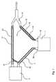
図1が、本発明による接続システムを有する換気システムの好ましい一実施形態の概略を示している。呼吸用加湿器1は、人工呼吸器3とY字形部品5との間に配置され、第1の吸気管または吸入管7と第2の吸気管または吸入管9とによって人工呼吸器3およびY字形部品5に接続されている。Y字形部品5の簡素に設計された端部は、矢印によって示されるように人工呼吸対象の患者へ向けられる。最後に、呼気または吐出管11は、人工呼吸器3とY字形部品5の残りの端部との間に配置される。 FIG. 1 shows a schematic of a preferred embodiment of a ventilation system with a connection system according to the invention. The breathing humidifier 1 is disposed between the ventilator 3 and the Y-shaped part 5, and the ventilator 3 and the Y-suction pipe 7 are connected to the ventilator 3 and the Y-suction pipe 7 by the first inhalation pipe or inhalation pipe 7. It is connected to the letter-shaped part 5. The simply designed end of the Y-shaped part 5 is directed to the patient to be ventilated as indicated by the arrow. Finally, the exhalation or
乾燥した呼吸ガスの流れは、人工呼吸器3において例えばブロア(図示されていない)によって生成され、このガスが換気装置を出て第1の吸気管7を通り、呼吸用加湿器1へ進む。呼吸用加湿器1において、呼吸ガスは、液体容器(図1には示されていない)へ周知の手法で導かれ、そこで加熱された液体によって加熱および加湿される。加熱および加湿された呼吸ガスは、呼吸用加湿器1から出て、第2の吸気管9を経てY字形部品5を介して患者へ供給される。 A flow of dry respiratory gas is generated in the ventilator 3 by, for example, a blower (not shown), and this gas exits the ventilator, passes through the first intake pipe 7 and proceeds to the respiratory humidifier 1. In the breathing humidifier 1, the breathing gas is led to a liquid container (not shown in FIG. 1) in a known manner where it is heated and humidified by the heated liquid. The heated and humidified breathing gas leaves the breathing humidifier 1 and is supplied to the patient via the second
人工呼吸器3によって制御される呼吸サイクルに従って、消費された呼吸用の空気が患者から流れ戻り、Y字形部品5において呼気管11へ入り、人工呼吸器3へ戻る。 According to the breathing cycle controlled by the ventilator 3, the consumed breathing air flows back from the patient, enters the
加熱ワイヤ13は、第2の吸気管9の壁へ一体化されており、このワイヤは、らせん状に巻かれており、加熱コイルとして機能する。さらに、Y字形部品5の近くの端部に配置された温度センサ17から呼吸用の空気の加湿器1の制御ユニット(図示されていない)へ信号を伝達する電気測定線15が第2の吸気管9に一体化されている。温度センサ17の位置は、患者にできるだけ近いが、できるだけ容易に交換できるように設計された換気配管系の一部であるように選択される。 The heating wire 13 is integrated with the wall of the
呼吸用加湿器1への第2の吸気管9の空圧的および電気的接続、すなわち吸入用ガスの接続ならびに加熱ワイヤ13および測定線15の接続は、第1の接続システム19によって達成される。 The pneumatic and electrical connection of the
呼気管11も、やはりらせん状に巻かれて加熱コイルを形成する加熱ワイヤ21の形態の管ヒータを備えている。呼気管11を加熱する理由は、患者から戻る呼吸ガスが呼気管11において凝縮し、例えば汚染された液体としてY字形部品5を通って患者へと流れ戻ることを防止することにある。呼気管11の管ヒータは、連続的であっても、あるいはいくつかの部分にて形成されてもよい。呼吸用加湿器1を始点として、第2の接続システム25、第1の吸気管7、および接続要素27を介して呼気管11へ進む電源線23によって、加熱ワイヤ21に電流が供給される。このようにして、第2の接続システム25は、呼吸用加湿器1への第1の吸気管7の空圧的および電気的接続、すなわち吸入用ガスの接続および電源線23の接続を呈する。 The
図2は、本発明による接続システムの好ましい一実施形態の一部分を備える液体容器4の斜視図である。液体容器4は、上部の両側に配置された2つの第1の接続要素6を備えている。2つの接続要素6間には凹部が形成されており、凹部は、ハウジングの突出部(図2では不図示)と結合して、図4〜図7に示されるように、容器がハウジングへ押し込まれてハウジングの突出部の周囲に嵌まることができるように設計されている。第1の接続要素6は、円形の断面を有する突き出した管状のソケットとして設計されているが、楕円形または多角形もしくは矩形の断面を有してもよい。 FIG. 2 is a perspective view of a
第1の接続要素6の各々から短い距離だけ離れて、すなわち第2の接続要素14の押し込みを可能にするための充分な距離だけ離れて、ガイド8が存在しており、ガイド8は、第2の接続要素14が第1の接続要素6へ容易に押し込まれることができるように、第2の接続要素14を軸方向に整列させる役目を果たす。また、第1の接続要素6が液体容器4の縁よりも突き出してはいないことは、見て取ることができる。これは、液体容器4がその後部または上部へと落下する場合に損傷を被りにくいという利点をもたらす。補給管10は、適切な接続片によって液体容器4へ接続されている。液体容器4の容積が限られているため、液体容器4の内部の水が特定の水準を下回って低下した場合に、補給管10によって新たな水が供給される。液体容器4の材料は、ポリエチレン(PE)またはポリプロピレン(PP)などの適切な透明プラスチックである。しかしながら、他の適切なプラスチック材料も、使用可能である。 A guide 8 is present at a short distance from each of the first connecting
図3が、本発明による接続システムの好ましい実施形態の一部分を備える吸気管9の斜視図である。第1の吸気管9の一端部は、接続片を形成しており、この接続片のうちの管から遠ざかる方を向いた端部が第2の接続要素14によって形成されている。さらに、接続片は、この接続片の片側に配置された第2の電気接触要素16を備えている。電気接触要素16は、突起18として設計された電気接点を備えている。また、接続片は、把持要素20も備えており、把持要素20は、接続片の側面、すなわち第2の電気接触要素16から約90°離れて位置しており、この把持要素20は、接続を断つための力が加わる地点として機能する。第2の接続要素14は、第2の電気接触要素16の反対側の外面に、軸方向に延びるとともに、図2に示したガイド8に係合可能な細長い突起12を備えている。視覚および触覚の両方の意味で魅力的な設計を実現するために、接続片は、接続システムが液体容器4に取り付けられた状態にあるときに実質的に閉じたカバー面を形成するように意図された斜めのスカートを備えている。 FIG. 3 is a perspective view of an
好ましい実施形態においては、第2の接続要素14は、ガイドに沿って第1の接続要素6へと最後まで押し込まれ、すなわちストッパとして機能する液体容器4に当接するまで圧入によって押し下げられる。あるいは、係止機構を2つの接続要素6、14の間に配置してもよく、例えば把持要素20を押すことによって再び解放することができる。 In a preferred embodiment, the second connecting
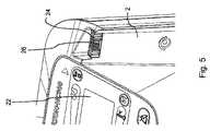
図4は、本発明による接続システムの好ましい実施形態の一部分を備える呼吸用加湿器1のハウジング2の斜視図である。ハウジング2は、水平部分および垂直部分を有する実質的に「L」字形状を有し、液体容器4(図4には示されていない)の液体を加熱するように機能する加熱板を水平部分に備えている。ハウジング2は、垂直部分の自由端のほぼ中央から延びる斜めの突出部を備えており、この突出部が、表示ユニットと操作要素とが設けられたユーザインターフェイス22を備えている。ハウジング2の内部は、とりわけ、例えば種々の温度センサから受信される信号にもとづいて加熱板の出力を調節することができる制御ユニットを備えている。さらに、ハウジング2は、本発明の範囲には属さない他の機能要素も備えることができる。ハウジング2の垂直部分の上部領域の側方に、図3に示した接続片の第2の電気接触要素16にはめ合わせられる第1の電気接触要素24が形成されている。 FIG. 4 is a perspective view of the
図5が、図4の右上領域の拡大図を示している。第1の電気接触要素24は、実質的に垂直なハウジングの壁の上端に配置され、切り欠きに設置されており、電気接点は、第2の電気接触要素16の突起18(図3を参照)と正確に結合する凹部26によって形成されていることを、見て取ることができる。図3および図5に示したとおりの電気接触要素16および24を併せて考慮することで、図3の接続片と図4のハウジング2との間の電気的接続を、上方からの挿入および水平方向に横からの挿入の両方によって達成できることを、導き出すことができる。 FIG. 5 shows an enlarged view of the upper right region of FIG. The first
図6は、本発明の好ましい実施形態による2つの独創的な接続システムを備えている呼吸用加湿器の斜視図である。図6の目的は、図2の液体容器4を図3の管接続片(2つ存在している)および図4に示したハウジング2に組み合わせることにある。液体容器4は、ハウジング2の開放領域へ水平方向に押し込まれており、もって、呼吸用加湿器1の加熱板が位置するハウジング2の下部に液体容器4の底部が実質的に位置する。2つの吸気管7、9の各々の一端部に1つずつ位置する接続片が、2つの第1の接続要素6の各々へと押し込まれている。 FIG. 6 is a perspective view of a respiratory humidifier comprising two inventive connection systems according to a preferred embodiment of the present invention. The purpose of FIG. 6 is to combine the
液体容器4がハウジング2に設置される前の状態において、第2の接続要素14を相手方部分、すなわち第1の接続要素6へと配置して、突起12がガイド8にはまり込むようにすると、管と液体容器4との間の空圧的接続だけが確立される。管7、9の電気測定線、加熱線、またはデータ線とハウジング2との電気的接続は、2つの異なるやり方のいずれかにて確立させることが可能である。 In a state before the
第1の可能性は、液体容器4をハウジング2へ挿入し、次いで管7、9を接続システムによって所定の位置に配置することであり、結果として空圧的および電気的接続が同時にに確立される。この場合の接続方向は、管の端部の軸方向に上方から垂直である。 The first possibility is to insert the
第2の可能性は、換気配管系が1回だけ使用される/使い捨ての物品として設計される場合に頻繁に使用される。この場合、液体容器4は、通常は完全な換気配管系と一緒に、すなわち液体容器4は、第1の吸気管7と第2の吸気管9と呼気管11とY字形部品5とが1つのユニットとして一体に接続された状態の構造体と一緒に提供され、作業員が実行すべき接続工程の数は最小限になる。液体容器4を呼吸用加湿器のハウジング2へ接続するために、液体容器は、ハウジング2へ水平方向、すなわち配管の方向および空気圧線の接続の方向に対して垂直な方向に挿入される。液体容器4およびハウジング2は、液体容器4がユーザにとって知覚可能な手法で所定の場所に係止されるように設計されている。図6は、ハウジング2における液体容器4の係止後の最終位置を示しており、液体容器4がハウジング2内の所定の位置に係止されるとき、接続片7、9の第2の電気接触要素16と第1の電気接触要素24の対応する相手方部分との電気的接続も確立される。ひとたび電気的接続および空圧的接続のすべてが適切に確立されると、制御ユニットは、音響信号を発することができ、あるいはこの状態をユーザインターフェイス22上に表示することができる。 The second possibility is frequently used when the ventilation piping system is used only once / designed as a disposable article. In this case, the
本発明により、換気管を呼吸用加湿器へと接続するための接続システムであって、電気接触要素について柔軟な設計の可能性を提供し、したがって呼吸用加湿器の設計の改善および魅力的な外観を可能にする接続システムがもたらされた。ここで、本発明による接続システムを、原理的には、第1の吸気管の第2の端部を換気装置へと接続するためにも使用でき、あるいは呼気管11を人工呼吸器3へと接続するためにも使用できることを、指摘しておかなければならない。 In accordance with the present invention, a connection system for connecting a ventilation tube to a respiratory humidifier provides the possibility of a flexible design for the electrical contact element, thus improving the design and attractiveness of the respiratory humidifier A connection system has been provided that allows the appearance. Here, the connection system according to the invention can in principle also be used to connect the second end of the first inspiratory tube to the ventilator, or the
Claims (10)
Translated fromJapanese前記接続システムは、
前記液体容器(4)に配置された第1の接続要素(6)と、
前記ハウジング(2)に配置された第1の電気接触要素(24)と、
前記換気管(7、9)へ接続可能である第2の接続要素(14)と、
を備えており、
前記第2の接続要素(14)は、前記換気管(7、9)の前記電気配線へ接続可能な第2の電気接触要素(16)を備えており、
前記液体容器(4)への前記換気管(7、9)の空圧的な接続が成立するように前記第1の接続要素(6)と前記第2の接続要素(14)とは第1の接続方向に互いに接続可能であり、
前記第2の電気接触要素(16)への前記第1の電気接触要素(24)の電気的接続は、前記液体容器(4)を前記ハウジング(2)へ挿入した後に、前記液体容器(4)への前記換気管(7、9)の空圧的な接続を成立させるときに前記第1の接続方向によって達成可能であり、あるいは、
前記第2の電気接触要素(16)への前記第1の電気接触要素(24)の電気的接続は、前記液体容器(4)への前記換気管(7、9)の空圧的な接続を成立させた後に、前記液体容器(4)を前記ハウジング(2)へ挿入するときに前記液体容器(4)を前記ハウジング(2)へ挿入する方向である、前記第1の接続方向に対して垂直な方向によっても達成可能であることを特徴とする接続システム。A connection system for connecting a ventilation pipe (7, 9) to a respirator (1), wherein the aspiration tube (7, 9) is provided with electrical wiring, and the respirator (1) Comprises a housing (2) anda liquid container (4)insertable into the housing (2) ,
The connection system includes:
A first connecting element (6) arranged in the liquid container (4);
A first electrical contact element (24) disposed in the housing (2);
A second connecting element (14) connectable to the ventilation pipe (7, 9);
With
The second connection element (14) comprises a second electrical contact element (16) connectable to the electrical wiring of the ventilation pipe (7, 9);
The first connection element (6) and the second connection element (14) are first so that a pneumatic connection of the ventilation pipes (7, 9) to the liquid container (4) is established. Can be connected to each other in the connection direction,
The electrical connection of the first electrical contact element (24) to the second electrical contact element (16) is such that after theliquid container (4) is inserted into the housing (2), the liquid container (4 ) Canbe achieved by the first connection directionwhen establishing a pneumatic connection of the ventilation pipe (7, 9) to), or
The electrical connection of the first electrical contact element (24) to the second electrical contact element (16) is the pneumatic connection of the ventilation pipes (7, 9) to the liquid container (4). When the liquid container (4) is inserted into the housing (2), the liquid container (4) is inserted into the housing (2) when the liquid container (4) is inserted into the housing (2). connection system characterized in that Te is achievable even byin thedirection perpendicular.
Applications Claiming Priority (3)
| Application Number | Priority Date | Filing Date | Title |
|---|---|---|---|
| DE102011054134ADE102011054134A1 (en) | 2011-10-01 | 2011-10-01 | Connection system for humidifier |
| DE102011054134.9 | 2011-10-01 | ||
| PCT/EP2012/069125WO2013045575A1 (en) | 2011-10-01 | 2012-09-27 | Connection system for a respiratory humidifier |
Publications (2)
| Publication Number | Publication Date |
|---|---|
| JP2014528259A JP2014528259A (en) | 2014-10-27 |
| JP6005747B2true JP6005747B2 (en) | 2016-10-12 |
Family
ID=47040686
Family Applications (1)
| Application Number | Title | Priority Date | Filing Date |
|---|---|---|---|
| JP2014532388AActiveJP6005747B2 (en) | 2011-10-01 | 2012-09-27 | Respiratory humidifier connection system |
Country Status (8)
| Country | Link |
|---|---|
| US (2) | US9937314B2 (en) |
| EP (1) | EP2760517B1 (en) |
| JP (1) | JP6005747B2 (en) |
| CN (1) | CN103842017B (en) |
| DE (1) | DE102011054134A1 (en) |
| ES (1) | ES2642277T3 (en) |
| NO (1) | NO2597030T3 (en) |
| WO (1) | WO2013045575A1 (en) |
Families Citing this family (29)
| Publication number | Priority date | Publication date | Assignee | Title |
|---|---|---|---|---|
| DK3685877T3 (en) | 2011-06-03 | 2023-10-02 | Fisher & Paykel Healthcare Ltd | MEDICAL TUBES CONSISTING OF CONDUCTIVE FILAMENTS AND METHODS OF PRODUCTION |
| NO2597030T3 (en)* | 2011-10-01 | 2017-12-30 | ||
| EP3738638A1 (en) | 2012-03-15 | 2020-11-18 | Fisher & Paykel Healthcare Limited | Respiratory gas humidification system |
| GB2575894A (en) | 2012-04-27 | 2020-01-29 | Fisher & Paykel Healthcare Ltd | Usability features for respiratory humidification system |
| CA3130843A1 (en)* | 2012-08-08 | 2014-02-13 | Fisher & Paykel Healthcare Limited | Breathing tube assemblies with adjustable elbow |
| GB2575363B (en) | 2012-11-14 | 2020-04-22 | Fisher & Paykel Healthcare Ltd | Zone heating for respiratory circuits |
| GB2527210B (en) | 2012-12-04 | 2020-02-05 | Fisher & Paykel Healthcare Ltd | A Breathing Tube and Method of Manufacturing a Breathing Tube |
| WO2014205513A1 (en) | 2013-06-25 | 2014-12-31 | Resmed Limited | Outlet connection assembly and method of making the same |
| GB2584026B (en) | 2013-09-13 | 2021-03-17 | Fisher & Paykel Healthcare Ltd | A heater base for supplying humidified gases to a patient |
| JP6663850B2 (en)* | 2013-09-13 | 2020-03-13 | フィッシャー アンド ペイケル ヘルスケア リミテッド | Humidification system connection |
| US10814091B2 (en) | 2013-10-24 | 2020-10-27 | Fisher & Paykel Healthcare Limited | System for delivery of respiratory gases |
| CN106029147B (en)* | 2013-12-20 | 2020-01-21 | 费雪派克医疗保健有限公司 | Humidification system connection |
| US10449319B2 (en) | 2014-02-07 | 2019-10-22 | Fisher & Paykel Healthcare Limited | Respiratory humidification system |
| CN111265754B (en)* | 2014-03-17 | 2023-06-06 | 费雪派克医疗保健有限公司 | Medical tube for respiratory system |
| US11173272B2 (en) | 2014-05-02 | 2021-11-16 | Fisher & Paykel Healthcare Limited | Gas humidification arrangement |
| CN110124174A (en) | 2014-05-13 | 2019-08-16 | 费雪派克医疗保健有限公司 | Availability aspect for breathing humidification system |
| CN106535971B (en) | 2014-06-03 | 2020-12-04 | 费雪派克医疗保健有限公司 | Flow mixers for respiratory therapy systems |
| WO2016080847A1 (en) | 2014-11-17 | 2016-05-26 | Fisher & Paykel Healthcare Limited | Humidification of respiratory gases |
| WO2017043981A1 (en) | 2015-09-09 | 2017-03-16 | Po-Yen Liu | Zone heating for respiratory circuits |
| JP7301744B2 (en) | 2016-10-11 | 2023-07-03 | フィッシャー アンド ペイケル ヘルスケア リミテッド | How to detect connection errors in humidification systems |
| EP3551978B1 (en) | 2016-12-07 | 2022-01-26 | Fisher&Paykel Healthcare Limited | Sensing arrangements for medical devices |
| EP3544662B1 (en) | 2016-12-22 | 2024-11-27 | Fisher & Paykel Healthcare Limited | Medical tubes and methods of manufacture |
| CN108030168A (en)* | 2018-01-24 | 2018-05-15 | 山东康力医疗器械科技有限公司 | A kind of portable mask and its application method |
| JP7526199B2 (en) | 2019-03-29 | 2024-07-31 | フィッシャー アンド ペイケル ヘルスケア リミテッド | System and method for detecting misconnections in a humidification system |
| US11839720B2 (en) | 2019-04-17 | 2023-12-12 | ResMed Pty Ltd | Humidification interface arrangements |
| CN116637264A (en) | 2019-04-17 | 2023-08-25 | 瑞思迈私人有限公司 | CPAP system |
| DE102020000422A1 (en)* | 2020-01-24 | 2021-07-29 | Drägerwerk AG & Co. KGaA | Electrical plug connection for a medical device arrangement |
| CN112156296A (en)* | 2020-09-08 | 2021-01-01 | 绍兴安迪斯医疗科技有限公司 | Novel outer wall heating breathing pipeline |
| USD1064254S1 (en) | 2021-10-21 | 2025-02-25 | Hamilton Medical Ag | Breathing tube for medical respiratory apparatus |
Family Cites Families (14)
| Publication number | Priority date | Publication date | Assignee | Title |
|---|---|---|---|---|
| DE19725875A1 (en) | 1997-06-18 | 1998-12-24 | Anesthesia Gmbh & Co Kg | Automatic coupling device for connecting breathing apparatus to respirator |
| DE19958296C1 (en) | 1999-12-03 | 2001-09-20 | Map Gmbh | Heated breathing tube for patient has heating element formed by tube wall and consisting of layer of electrically conductive synthetic material, voltage supply line integrated into tube wall |
| SE0000605D0 (en) | 2000-02-24 | 2000-02-24 | Siemens Elema Ab | Conduit for connecting a fluid transfer device to a patient |
| US7120354B2 (en) | 2000-03-21 | 2006-10-10 | Fisher & Paykel Healthcare Limited | Gases delivery conduit |
| US6953354B2 (en)* | 2002-06-05 | 2005-10-11 | Fisher & Paykel Healthcare Limited | Connector for breathing conduits |
| EP1542756B1 (en)* | 2002-08-30 | 2016-10-19 | Fisher & Paykel Healthcare Limited | Humidification system |
| DE102006034028B4 (en)* | 2005-08-01 | 2025-07-10 | Löwenstein Medical Technology S.A. | Ventilation device |
| CN102133447B (en)* | 2005-08-15 | 2015-01-07 | 瑞思迈有限公司 | Humidifier and/or flow generator for CPAP device |
| EP2079505B1 (en)* | 2006-11-08 | 2020-07-15 | ResMed Pty Ltd | Conduit for use in a respiratory apparatus |
| MX2010001827A (en)* | 2007-08-14 | 2010-06-01 | Plastiflex Belgium | A respiratory system. |
| TW200922009A (en)* | 2007-12-07 | 2009-05-16 | Jye Chuang Electronic Co Ltd | Contact terminal |
| IT1393213B1 (en)* | 2009-03-17 | 2012-04-11 | Covidien Ag | SYSTEM FOR CONDITIONING RESPIRATORY GASES |
| AU2010206053B2 (en)* | 2009-07-31 | 2014-08-07 | ResMed Pty Ltd | Wire Heated Tube with Temperature Control System, Tube Type Detection, and Active Over Temperature Protection for Humidifier for Respiratory Apparatus |
| NO2597030T3 (en)* | 2011-10-01 | 2017-12-30 |
- 2011
- 2011-07-12NONO13156118Apatent/NO2597030T3/nounknown
- 2011-10-01DEDE102011054134Apatent/DE102011054134A1/ennot_activeWithdrawn
- 2012
- 2012-09-27JPJP2014532388Apatent/JP6005747B2/enactiveActive
- 2012-09-27EPEP12773277.4Apatent/EP2760517B1/enactiveActive
- 2012-09-27ESES12773277.4Tpatent/ES2642277T3/enactiveActive
- 2012-09-27WOPCT/EP2012/069125patent/WO2013045575A1/enactiveApplication Filing
- 2012-09-27CNCN201280048478.0Apatent/CN103842017B/enactiveActive
- 2012-09-27USUS14/348,969patent/US9937314B2/enactiveActive
- 2016
- 2016-12-28USUS15/392,109patent/US9937316B2/enactiveActive
Also Published As
| Publication number | Publication date |
|---|---|
| US9937314B2 (en) | 2018-04-10 |
| ES2642277T3 (en) | 2017-11-16 |
| WO2013045575A1 (en) | 2013-04-04 |
| DE102011054134A1 (en) | 2013-04-04 |
| CN103842017A (en) | 2014-06-04 |
| WO2013045575A8 (en) | 2013-05-23 |
| CN103842017B (en) | 2016-10-19 |
| EP2760517A1 (en) | 2014-08-06 |
| US20170106162A1 (en) | 2017-04-20 |
| JP2014528259A (en) | 2014-10-27 |
| NO2597030T3 (en) | 2017-12-30 |
| US20140246021A1 (en) | 2014-09-04 |
| US9937316B2 (en) | 2018-04-10 |
| EP2760517B1 (en) | 2017-08-02 |
Similar Documents
| Publication | Publication Date | Title |
|---|---|---|
| JP6005747B2 (en) | Respiratory humidifier connection system | |
| CN103842013B (en) | Snorkel system | |
| US10940284B2 (en) | Breathing tube | |
| EP1369141B1 (en) | Connector for the pneumatical and electrical coupling between a gases supply means and a gas conduit | |
| US9555211B2 (en) | Apparatus for humidifying a respiratory gas | |
| CN103930152B (en) | Tubes for respirator systems | |
| CN108211078A (en) | For the connection of humidification system | |
| GB2559913A (en) | Conduit connector for a patient breathing device | |
| CN101018582A (en) | device for measuring properties of gas supplied to a patient | |
| CN108619601A (en) | A heating tube for respiratory system, respiratory system and control method thereof | |
| CN110585539A (en) | Universal heating pipeline sleeve for breathing machine pipeline | |
| CN208212278U (en) | Warming humidification switching device | |
| TW202428224A (en) | Medical tubes for a breathing circuit | |
| HK1255497B (en) | Respiratory gas conduit with a connector for the pneumatical and electrical coupling to a respiratory gas supply means | |
| AU2005201817A1 (en) | Device for Supplying a Respiratory Gas, Humidifying Device, Respiratory Gas Tube, and Connecting Device Therefor |
Legal Events
| Date | Code | Title | Description |
|---|---|---|---|
| A977 | Report on retrieval | Free format text:JAPANESE INTERMEDIATE CODE: A971007 Effective date:20150410 | |
| A131 | Notification of reasons for refusal | Free format text:JAPANESE INTERMEDIATE CODE: A131 Effective date:20150421 | |
| A601 | Written request for extension of time | Free format text:JAPANESE INTERMEDIATE CODE: A601 Effective date:20150721 | |
| A521 | Request for written amendment filed | Free format text:JAPANESE INTERMEDIATE CODE: A523 Effective date:20150731 | |
| A131 | Notification of reasons for refusal | Free format text:JAPANESE INTERMEDIATE CODE: A131 Effective date:20160202 | |
| A521 | Request for written amendment filed | Free format text:JAPANESE INTERMEDIATE CODE: A523 Effective date:20160427 | |
| TRDD | Decision of grant or rejection written | ||
| A01 | Written decision to grant a patent or to grant a registration (utility model) | Free format text:JAPANESE INTERMEDIATE CODE: A01 Effective date:20160823 | |
| A61 | First payment of annual fees (during grant procedure) | Free format text:JAPANESE INTERMEDIATE CODE: A61 Effective date:20160907 | |
| R150 | Certificate of patent or registration of utility model | Ref document number:6005747 Country of ref document:JP Free format text:JAPANESE INTERMEDIATE CODE: R150 | |
| S111 | Request for change of ownership or part of ownership | Free format text:JAPANESE INTERMEDIATE CODE: R313113 | |
| R350 | Written notification of registration of transfer | Free format text:JAPANESE INTERMEDIATE CODE: R350 | |
| R250 | Receipt of annual fees | Free format text:JAPANESE INTERMEDIATE CODE: R250 | |
| R250 | Receipt of annual fees | Free format text:JAPANESE INTERMEDIATE CODE: R250 | |
| R250 | Receipt of annual fees | Free format text:JAPANESE INTERMEDIATE CODE: R250 | |
| R250 | Receipt of annual fees | Free format text:JAPANESE INTERMEDIATE CODE: R250 | |
| R250 | Receipt of annual fees | Free format text:JAPANESE INTERMEDIATE CODE: R250 | |
| R250 | Receipt of annual fees | Free format text:JAPANESE INTERMEDIATE CODE: R250 | |
| R250 | Receipt of annual fees | Free format text:JAPANESE INTERMEDIATE CODE: R250 |