JP6001555B2 - Resonance mechanism for linear compressors. - Google Patents
Resonance mechanism for linear compressors.Download PDFInfo
- Publication number
- JP6001555B2 JP6001555B2JP2013546528AJP2013546528AJP6001555B2JP 6001555 B2JP6001555 B2JP 6001555B2JP 2013546528 AJP2013546528 AJP 2013546528AJP 2013546528 AJP2013546528 AJP 2013546528AJP 6001555 B2JP6001555 B2JP 6001555B2
- Authority
- JP
- Japan
- Prior art keywords
- spring
- clamping
- resonance
- resonant
- tubular body
- Prior art date
- Legal status (The legal status is an assumption and is not a legal conclusion. Google has not performed a legal analysis and makes no representation as to the accuracy of the status listed.)
- Expired - Fee Related
Links
- 230000007246mechanismEffects0.000titleclaimsdescription37
- 230000007935neutral effectEffects0.000description4
- 230000008859changeEffects0.000description3
- 230000006835compressionEffects0.000description3
- 238000007906compressionMethods0.000description3
- 230000008878couplingEffects0.000description2
- 238000010168coupling processMethods0.000description2
- 238000005859coupling reactionMethods0.000description2
- 230000007257malfunctionEffects0.000description2
- 238000010521absorption reactionMethods0.000description1
- 230000002411adverseEffects0.000description1
- 238000010276constructionMethods0.000description1
- 239000002826coolantSubstances0.000description1
- 230000000694effectsEffects0.000description1
- 229920001971elastomerPolymers0.000description1
- 239000000806elastomerSubstances0.000description1
- 239000012530fluidSubstances0.000description1
- 239000000463materialSubstances0.000description1
- 238000000034methodMethods0.000description1
- 230000010363phase shiftEffects0.000description1
- 230000008569processEffects0.000description1
- 238000005057refrigerationMethods0.000description1
- 125000006850spacer groupChemical group0.000description1
- 238000006467substitution reactionMethods0.000description1
Images


Classifications
- F—MECHANICAL ENGINEERING; LIGHTING; HEATING; WEAPONS; BLASTING
- F04—POSITIVE - DISPLACEMENT MACHINES FOR LIQUIDS; PUMPS FOR LIQUIDS OR ELASTIC FLUIDS
- F04B—POSITIVE-DISPLACEMENT MACHINES FOR LIQUIDS; PUMPS
- F04B35/00—Piston pumps specially adapted for elastic fluids and characterised by the driving means to their working members, or by combination with, or adaptation to, specific driving engines or motors, not otherwise provided for
- F04B35/04—Piston pumps specially adapted for elastic fluids and characterised by the driving means to their working members, or by combination with, or adaptation to, specific driving engines or motors, not otherwise provided for the means being electric
- F—MECHANICAL ENGINEERING; LIGHTING; HEATING; WEAPONS; BLASTING
- F01—MACHINES OR ENGINES IN GENERAL; ENGINE PLANTS IN GENERAL; STEAM ENGINES
- F01B—MACHINES OR ENGINES, IN GENERAL OR OF POSITIVE-DISPLACEMENT TYPE, e.g. STEAM ENGINES
- F01B3/00—Reciprocating-piston machines or engines with cylinder axes coaxial with, or parallel or inclined to, main shaft axis
- F01B3/0002—Reciprocating-piston machines or engines with cylinder axes coaxial with, or parallel or inclined to, main shaft axis having stationary cylinders
- F01B3/0017—Component parts, details, e.g. sealings, lubrication
- F01B3/0023—Actuating or actuated elements
- F—MECHANICAL ENGINEERING; LIGHTING; HEATING; WEAPONS; BLASTING
- F04—POSITIVE - DISPLACEMENT MACHINES FOR LIQUIDS; PUMPS FOR LIQUIDS OR ELASTIC FLUIDS
- F04B—POSITIVE-DISPLACEMENT MACHINES FOR LIQUIDS; PUMPS
- F04B35/00—Piston pumps specially adapted for elastic fluids and characterised by the driving means to their working members, or by combination with, or adaptation to, specific driving engines or motors, not otherwise provided for
- F04B35/04—Piston pumps specially adapted for elastic fluids and characterised by the driving means to their working members, or by combination with, or adaptation to, specific driving engines or motors, not otherwise provided for the means being electric
- F04B35/045—Piston pumps specially adapted for elastic fluids and characterised by the driving means to their working members, or by combination with, or adaptation to, specific driving engines or motors, not otherwise provided for the means being electric using solenoids
- F—MECHANICAL ENGINEERING; LIGHTING; HEATING; WEAPONS; BLASTING
- F16—ENGINEERING ELEMENTS AND UNITS; GENERAL MEASURES FOR PRODUCING AND MAINTAINING EFFECTIVE FUNCTIONING OF MACHINES OR INSTALLATIONS; THERMAL INSULATION IN GENERAL
- F16F—SPRINGS; SHOCK-ABSORBERS; MEANS FOR DAMPING VIBRATION
- F16F15/00—Suppression of vibrations in systems; Means or arrangements for avoiding or reducing out-of-balance forces, e.g. due to motion
- F16F15/02—Suppression of vibrations of non-rotating, e.g. reciprocating systems; Suppression of vibrations of rotating systems by use of members not moving with the rotating systems
- F16F15/04—Suppression of vibrations of non-rotating, e.g. reciprocating systems; Suppression of vibrations of rotating systems by use of members not moving with the rotating systems using elastic means
- F16F15/043—Suppression of vibrations of non-rotating, e.g. reciprocating systems; Suppression of vibrations of rotating systems by use of members not moving with the rotating systems using elastic means acting on a cam follower
- F—MECHANICAL ENGINEERING; LIGHTING; HEATING; WEAPONS; BLASTING
- F16—ENGINEERING ELEMENTS AND UNITS; GENERAL MEASURES FOR PRODUCING AND MAINTAINING EFFECTIVE FUNCTIONING OF MACHINES OR INSTALLATIONS; THERMAL INSULATION IN GENERAL
- F16F—SPRINGS; SHOCK-ABSORBERS; MEANS FOR DAMPING VIBRATION
- F16F3/00—Spring units consisting of several springs, e.g. for obtaining a desired spring characteristic
- F16F3/02—Spring units consisting of several springs, e.g. for obtaining a desired spring characteristic with springs made of steel or of other material having low internal friction
- F—MECHANICAL ENGINEERING; LIGHTING; HEATING; WEAPONS; BLASTING
- F16—ENGINEERING ELEMENTS AND UNITS; GENERAL MEASURES FOR PRODUCING AND MAINTAINING EFFECTIVE FUNCTIONING OF MACHINES OR INSTALLATIONS; THERMAL INSULATION IN GENERAL
- F16J—PISTONS; CYLINDERS; SEALINGS
- F16J15/00—Sealings
- F16J15/02—Sealings between relatively-stationary surfaces
- F16J15/021—Sealings between relatively-stationary surfaces with elastic packing
- F16J15/022—Sealings between relatively-stationary surfaces with elastic packing characterised by structure or material
- F—MECHANICAL ENGINEERING; LIGHTING; HEATING; WEAPONS; BLASTING
- F16—ENGINEERING ELEMENTS AND UNITS; GENERAL MEASURES FOR PRODUCING AND MAINTAINING EFFECTIVE FUNCTIONING OF MACHINES OR INSTALLATIONS; THERMAL INSULATION IN GENERAL
- F16J—PISTONS; CYLINDERS; SEALINGS
- F16J15/00—Sealings
- F16J15/02—Sealings between relatively-stationary surfaces
- F16J15/04—Sealings between relatively-stationary surfaces without packing between the surfaces, e.g. with ground surfaces, with cutting edge
Landscapes
- Engineering & Computer Science (AREA)
- General Engineering & Computer Science (AREA)
- Mechanical Engineering (AREA)
- Physics & Mathematics (AREA)
- Acoustics & Sound (AREA)
- Aviation & Aerospace Engineering (AREA)
- Compressors, Vaccum Pumps And Other Relevant Systems (AREA)
- Compressor (AREA)
Description
Translated fromJapanese本発明は、圧縮機用の共振機構に関し、より詳細には、装着形態が中立点を通してなされ、中立点と装置シェルの間に可撓性を与える切欠部が設けられた管状構成要素を有する、機構に関する。 The present invention relates to a resonance mechanism for a compressor, and more particularly, has a tubular component that is mounted through a neutral point and provided with a notch that provides flexibility between the neutral point and the device shell. Regarding the mechanism.
圧縮機の機能は、仕切られた流体体積の圧力を冷凍サイクルを実施するのに必要とされる圧力に増大させることである。ピストンがシリンダ内で往復移動で摺動してガス圧縮を実施する、いわゆるオルタネート圧縮機が当技術分野で知られている。 The function of the compressor is to increase the pressure of the partitioned fluid volume to the pressure required to perform the refrigeration cycle. So-called alternate compressors are known in the art in which a piston slides back and forth within a cylinder to effect gas compression.
リニア圧縮機では、ピストンはリニア電気モータによって駆動される。作動要素がモータとピストンの間に結合され、それにより、モータにピストンを駆動させてピストン室内で往復運動で移動させる。ピストンは、通常、作動要素に堅固に配置されて保たれ、それにより、ピストンおよび作動要素は、結合した動作で移動する傾向があり、そのため望ましくないことに過剰な振動が引き起こされる。 In a linear compressor, the piston is driven by a linear electric motor. An actuating element is coupled between the motor and the piston, thereby causing the motor to drive the piston and reciprocatingly move within the piston chamber. The piston is usually kept tightly placed on the actuating element so that the piston and actuating element tend to move in a coupled motion, which undesirably causes excessive vibrations.
この不都合性を解消するために、ブラジル特許出願第0601645−6号明細書は、作動要素が、1つまたは2つの(この出願の図では数字70で示される)共振らせんばねの形態の弾性要素を用いてピストンに結合される圧縮機を説明している。したがって、ピストンおよび締め付け要素は弾性要素の端部上に装着され、モータ磁石およびその締め付け具は他方の端部上に装着され、それにより、圧縮機振動の固有モードでは、2つの端部間の位相移動における位相差は180°であり、この弾性要素内には、軸方向の振動がゼロになる傾向がある領域が存在している。弾性要素内のこの領域は、こうして中立点と呼ばれている。 To overcome this disadvantage, Brazil patent application 0601645-6 describes an elastic element in the form of one or two actuating elements (represented by numeral 70 in the figure of this application) of a resonant helical spring. Is used to describe a compressor coupled to a piston. Thus, the piston and clamping element are mounted on the end of the elastic element, and the motor magnet and its clamp are mounted on the other end, so that in the natural mode of compressor vibration, between the two ends The phase difference in the phase shift is 180 °, and a region in which the axial vibration tends to become zero exists in this elastic element. This region in the elastic element is thus called the neutral point.
特許出願のブラジル特許出願第0601645−6号明細書の教示によれば、シリンダと共振ばねの結合は、圧縮機の振動の固有モードが変更されないように、この中立点を通して実施されなければならない。 According to the teaching of the patent application Brazil patent application 0601645-6, the coupling of the cylinder and the resonant spring must be carried out through this neutral point so that the natural mode of vibration of the compressor is not changed.
そのような装着を実施するために、文献ブラジル特許出願第0601645−6号明細書の圧縮機は、弾性媒体をシリンダに結合させる位置要素をさらに有する。位置要素(この出願の図では数字80によって示される)は、共振ばねとの剛性連結を有し、説明された構造の1つにおいては、要素80は、シェルに固着された配置ロッド板ばね(この出願の図では数字84のばねを参照)に関連付けられる。 In order to carry out such a mounting, the compressor of document Brazil Patent Application No. 0601645-6 further comprises a position element for coupling the elastic medium to the cylinder. The position element (indicated by the numeral 80 in the figure of this application) has a rigid connection with the resonant spring, and in one of the structures described, the element 80 is a placement rod leaf spring (secured to the shell). In the figure of this application (see spring number 84).
上記の構造は、当技術分野で知られているリニア圧縮機に対する技術的進歩を表しているが、ここで提供される構造は、共振セット上に作用する力が不均衡の力であるとき、この機構を正しく配置して維持するのに十分な軸方向の剛性を有することができないという欠点をもたらす。そのような不均衡な力は、共振セット上にゼロではない軸方向の力を結果的に生じさせることがあり、それによってモータを変位させ、圧縮機の効率に悪影響を及ぼすことがあり、モータとシェルの間に衝突を発生させていくつかの不具合を引き起こす可能性さえある。 While the above structure represents a technical advance over a linear compressor known in the art, the structure provided here is when the force acting on the resonant set is an unbalanced force: This has the disadvantage that it cannot have sufficient axial stiffness to properly place and maintain this mechanism. Such an unbalanced force can result in a non-zero axial force on the resonant set, thereby displacing the motor and adversely affecting the efficiency of the compressor. Can even cause some conflicts between the shell and the shell.
そのような不均衡を引き起こし得る条件のうち、圧縮機の電源が切られたときのモータ強度、冷却剤装填プロセス中のガス強度、および圧縮機の作動中に発生し得る不均衡の力、特にガス圧縮および拡張力ならびにモータ力に対するものの存在がある。 Among the conditions that can cause such an imbalance, motor strength when the compressor is turned off, gas strength during the coolant loading process, and imbalance forces that can occur during compressor operation, in particular There is a presence for gas compression and expansion forces and motor forces.
したがって、本発明の目的の1つは、ばね締め付け点と圧縮機シェルの間に特定の軸方向の可撓性をもたらすことができ、それにより、不均衡の力の状況において圧縮機共振セットを圧縮機シェルの周りに軸方向に配置して保つのに十分な最小限の剛性を与える圧縮機用の共振機構であって、圧縮機振動の固有モードを変化させない十分な最大限の剛性を有する、圧縮機用の共振機構を開示することである。 Accordingly, one of the objects of the present invention is to provide a certain axial flexibility between the spring clamping point and the compressor shell, thereby allowing the compressor resonance set to be in an unbalanced force situation. Resonance mechanism for a compressor that provides a minimum stiffness sufficient to be axially placed around the compressor shell and has a maximum stiffness that does not change the natural mode of compressor vibration It is to disclose a resonance mechanism for a compressor.
本発明は、管状本体と、管状本体内に収容された共振ばねとを備える圧縮機用の共振機構であって、管状本体が、共振ばね用の締め付け点が設けられる軸方向に可撓性の表面を画定する少なくとも1つのスロットセットを備える、圧縮機用の共振機構によって上記の目的に到達する。 The present invention relates to a resonance mechanism for a compressor comprising a tubular body and a resonance spring housed in the tubular body, wherein the tubular body is flexible in the axial direction where a fastening point for the resonance spring is provided. The above objective is reached by a resonant mechanism for a compressor comprising at least one set of slots defining a surface.
本発明の好ましい実施形態では、共振ばね用の、互いに向かい合う少なくとも2つの締め付け点が設けられ、機構は、2つのスロットセットを備え、各々のセットは、共振ばね用の2つの締め付け点の各々が設けられる軸方向に可撓性の表面を画定する。 In a preferred embodiment of the present invention, at least two clamping points for the resonant spring are provided opposite each other, the mechanism comprises two slot sets, each set having two clamping points for the resonant spring each A provided axially flexible surface is defined.
さらに本発明の好ましい実施形態では、機構は、共振ばねを管状本体に締め付けるための少なくとも1つの締め付けセットを備え、締め付けセットは、共振ばねの締め付け穴内に設けられた内側の雌型締め付け要素と、管状本体表面の締め付け穴を通り抜ける外側の雄型締め付け要素とを備える。Furthermore, in a preferred embodiment of the invention, the mechanism comprises at least one clamping set for clamping the resonant spring to the tubular body, the clamping set comprising an innerfemale clamping element provided in a clamping hole of the resonant spring; An outermale clamping element passing through a clamping hole in the surface of the tubular body.
したがって、スロットは、表面が形成されるように、締め付け穴周りで互いから分離する隣接スロット、または表面および表面に弾性を付与するためのばね部分とを形成する鏡像型スロットを備えることができる。 Thus, the slots can comprise mirror-type slots that form adjacent slots that separate from each other around the clamping hole, or a spring portion for imparting elasticity to the surface, such that the surface is formed.
好ましくは、表面はほぼ楕円体の形態であり、機構は、さらに、管状本体の各端部に設けられたリーフ板ばねを備える。 Preferably, the surface is in the form of an ellipsoid and the mechanism further comprises a leaf leaf spring provided at each end of the tubular body.
本発明は、これ以後、添付の図に表された実施形態の例に基づいてより詳細に説明される。 The invention will now be described in more detail on the basis of an example of an embodiment represented in the attached figures.
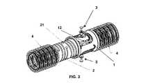
図1および図2は、本発明の共振機構が適用されるリニア圧縮機の共振セットを示している。 1 and 2 show a resonance set of a linear compressor to which the resonance mechanism of the present invention is applied.
これらの図に見られ得るように、リニア圧縮機の共振セットは、基本的には、シリンダまたは圧縮室(図示されず)内の往復運動ピストンPを備える。ピストンPは、弾性要素(らせんばね)Eの一方の端部上にピストン締め付け要素FPによって装着され、作動要素は、弾性要素Eの他方の端部上に締め付け要素FMによって装着される。作動要素は、たとえば、図2に示されるものなどの非磁性構成要素NMに関連付けられたモータ磁石Iなどの構成要素モータを備えることができる。 As can be seen in these figures, the resonant set of a linear compressor basically comprises a reciprocating piston P in a cylinder or compression chamber (not shown). The piston P is mounted on one end of an elastic element (helical spring) E by a piston clamping element FP, and the actuating element is mounted on the other end of the elastic element E by a clamping element FM. The actuating element may comprise a component motor such as, for example, a motor magnet I associated with a non-magnetic component NM such as that shown in FIG.
板ばねMPのセットが、共振セットを非線形圧縮機シェル(図示されず)に締め付けるために弾性手段の各端部に設けられ得る。 A set of leaf springs MP can be provided at each end of the elastic means to clamp the resonant set to a non-linear compressor shell (not shown).
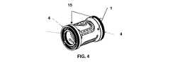
図3、図4、図5、および図7は、本発明による共振機構の好ましい実施形態を示している。 3, 4, 5 and 7 show preferred embodiments of the resonance mechanism according to the present invention.
好ましい実施形態では、圧縮機用の共振機構は、管状本体1の形態の位置決め要素が設けられた図1および2に示されたものなどの共振セットを備え、位置決め要素は、結果として生じた非ゼロの軸方向力の状況において共振セットを圧縮機シェルの周りに軸方向に配置して保つのに十分な最小限の剛性をこのセットに与えることができ、圧縮機振動の固有モードを変化させない十分な最大限の剛性を与える。 In a preferred embodiment, the resonance mechanism for the compressor comprises a resonance set such as that shown in FIGS. 1 and 2 provided with a positioning element in the form of a
したがって、管状本体1は、その内部に共振ばね2を収容し、ピストン圧縮機は共振ばね2の一方の端部上に装着され、ピストン作動要素は弾性ばねの他方の端部上に装着される。 Thus, the
本発明の好ましい実施形態では、本体1の共振ばね2への締め付けは、2つの締め付けセット3によって実施され、各々のセットは、好ましくは管状本体の対向する位置に締め付けられる。この好ましい締め付けは、図5および5aに概略的に示されており、これらの図における管状本体1は、締め付けの理解を容易にするために、詳細を有さない本体として概略的に示されている。 In a preferred embodiment of the invention, the clamping of the
したがって、図5および図5aに見られ得るように、本発明の好ましい実施形態では、各々の締め付けセット3は、共振ばね2の締め付け穴21内に設けられた内側の雌型締め付け要素31と、本体11の締め付け穴11を通り抜ける外側の雄型締め付け要素35とを備える。図に見られ得るように、締め付けセットは、さらに、座金34およびエラストマーリング33を備えることができる。Thus, as can be seen in FIGS. 5 and 5a, in a preferred embodiment of the invention, each
図6および図6aは、本発明の代替の実施形態の締め付けセットを示しており、この場合、図5および5aの要素に加えて、第2の座金32が設けられる。 Figures 6 and 6a show an alternative embodiment clamping set of the present invention, in which a
結果として生じた軸方向力がゼロであろうとなかろうと、機構全体としての機能を損なうことなくこれらの力の適切な吸収を確実にするために、管状本体1は、好ましくは、2つのスロットセット12を備え、各々のセットは、共振ばねを締め付けるための穴11が設けられる軸方向に可撓性の表面13を画定する少なくとも2つのスロット12を備える。こうして、スロット12によって形成された材料の不在は、部分13に特定の軸方向の可撓性を付与し、一方では管状本体1の残りの部分は、圧縮機振動の固有モードを変化させないために必要とされる軸方向の剛性を維持する。 To ensure proper absorption of these forces without compromising the overall function of the mechanism, whether or not the resulting axial force is zero, the
好ましくは、表面13は、ほぼ楕円の形態の中央部分を有する。 Preferably, the
図3、図4、図5、および図7は、本発明による共振機構の好ましい実施形態を示しており、この場合、各セットのスロット12は、穴11の周りで互いから分離し、それによって表面13が形成される隣接スロットを備える。 3, 4, 5, and 7 show a preferred embodiment of the resonant mechanism according to the present invention, in which each set of
この実施形態では、スロット12の各々の端部は、応力集中領域がこれらの端部に生じることを防止する方向転換部12aを有する。 In this embodiment, each end of the
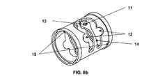
さらに、図8aおよび8bに示される代替の実施形態では、スロット12は、楕円表面13と、部分13の交差弾性を付与するばね部分14とを形成する鏡像型スロットを備える。 Furthermore, in the alternative embodiment shown in FIGS. 8 a and 8 b, the
表面13によって与えられた前記交差可撓性は、本発明の共振機構が、共振セット上に作用する、結果として生じる非ゼロの軸方向力を生み出し得る不均衡力を補償することを可能にする。 The cross-flexibility provided by the
図に示される本発明の好ましい実施形態では、さらに、管状本体1の円形側面15に合わせて、スペーサ(図示されず)を備えて交互にかつ連続的に装着されたリーフ板ばね4が設けられる。これらの板ばねの機能の1つは、共振セットを圧縮機シェル(図示されず)に固着させることである。板ばねの別の機能は、圧縮機作動中の同心度の誤差が最小限に抑えられることを確実にすることである。これらの同心度の誤差は、過剰なとき、モータの機能不全および/または圧縮機の機能不全を生じさせる最悪なピストン摩耗を引き起こす。 In the preferred embodiment of the present invention shown in the figures,
本発明の好ましい構築方法が示されてきたが、特許請求された保護の趣旨および範囲から逸脱することなく、当業者によっていかなる省略、代用、および構造的変更も実施されてよいことが理解されることは言うに値する。また、同じ結果を実現するためにほぼ同じ方法で同じ機能を実施する要素のすべての組み合わせが、本発明の範囲内にあることも明確に規定される。説明された実施形態の要素を他のものと取り換えることもまた、完全に意図され企図される。 While preferred construction methods of the invention have been shown, it is understood that any omissions, substitutions, and structural changes may be made by those skilled in the art without departing from the spirit and scope of the claimed protection. That deserves to be said. It is also clearly defined that all combinations of elements that perform the same function in substantially the same way to achieve the same result are within the scope of the invention. Replacing the elements of the described embodiments with others is also fully contemplated and contemplated.
したがって、上記で図に基づいて提供された説明は、本発明の機構に対して可能となる実施形態の一部に関するものにすぎず、本発明の目的の真の範囲は、付属の特許請求項の範囲内で定義されることを理解されたい。 Accordingly, the description provided above with reference to the drawings merely relates to some of the possible embodiments for the mechanism of the present invention, and the true scope of the present invention is defined by the appended claims. It should be understood that it is defined within the scope of
Claims (8)
Translated fromJapanese管状本体(1)と、
管状本体(1)の内部に締結された共振ばね(2)とを備えており、
共振ばね(2)は、該共振ばね(2)の一方の端部にピストンPが取り付けられ、該共振ばね(2)の他方の端部に作動要素が取り付けられるものであり、
管状本体(1)が、締め付け点が設けられた軸方向に可撓性の表面(13)を画定する少なくとも1つのスロットセット(12)を備えており、
共振ばね(2)が前記締め付け点に締結されていることを特徴とする、前記共振機構。A resonant mechanism for a linear compressor comprising at least one piston P and at least one actuating element,
A tubular body (1);
The innerportionof the tubular body (1)provided with afastening resonant spring (2),
The resonance spring (2) has a piston P attached to one end of the resonance spring (2) and an actuating element attached to the other end of the resonance spring (2).
The tubular body (1) isprovided with at least one set of slots defining a surface (13) flexible in the axialdirection Tightening points areprovided(12),
Resonant spring (2) it is characterized that youhave been fastened to the fastening point,the resonance mechanism.
Applications Claiming Priority (3)
| Application Number | Priority Date | Filing Date | Title |
|---|---|---|---|
| BRPI1005184-8ABRPI1005184B1 (en) | 2010-12-27 | 2010-12-27 | RESONANT MECHANISM FOR LINEAR COMPRESSORS |
| BRPI1005184-8 | 2010-12-27 | ||
| PCT/BR2011/000461WO2012088572A1 (en) | 2010-12-27 | 2011-12-08 | Resonant mechanism for linear compressors |
Publications (2)
| Publication Number | Publication Date |
|---|---|
| JP2014501354A JP2014501354A (en) | 2014-01-20 |
| JP6001555B2true JP6001555B2 (en) | 2016-10-05 |
Family
ID=46382112
Family Applications (1)
| Application Number | Title | Priority Date | Filing Date |
|---|---|---|---|
| JP2013546528AExpired - Fee RelatedJP6001555B2 (en) | 2010-12-27 | 2011-12-08 | Resonance mechanism for linear compressors. |
Country Status (11)
| Country | Link |
|---|---|
| US (1) | US9388694B2 (en) |
| EP (1) | EP2659139B1 (en) |
| JP (1) | JP6001555B2 (en) |
| KR (1) | KR20140019774A (en) |
| CN (1) | CN103299074B (en) |
| AR (1) | AR084601A1 (en) |
| BR (1) | BRPI1005184B1 (en) |
| ES (1) | ES2733173T3 (en) |
| SG (1) | SG191411A1 (en) |
| TW (1) | TWI447301B (en) |
| WO (1) | WO2012088572A1 (en) |
Families Citing this family (14)
| Publication number | Priority date | Publication date | Assignee | Title |
|---|---|---|---|---|
| EP1905465B2 (en) | 2006-09-28 | 2013-11-27 | Smith & Nephew, Inc. | Portable wound therapy system |
| ES2715605T3 (en) | 2007-11-21 | 2019-06-05 | Smith & Nephew | Wound dressing |
| GB201015656D0 (en) | 2010-09-20 | 2010-10-27 | Smith & Nephew | Pressure control apparatus |
| US9067003B2 (en) | 2011-05-26 | 2015-06-30 | Kalypto Medical, Inc. | Method for providing negative pressure to a negative pressure wound therapy bandage |
| BRPI1103355A2 (en)* | 2011-07-04 | 2013-07-23 | Whirlpool Sa | adapter device for linear compressor, and compressor provided with said device |
| BRPI1103647A2 (en) | 2011-07-07 | 2013-07-02 | Whirlpool Sa | arrangement between linear compressor components |
| BRPI1103447A2 (en)* | 2011-07-19 | 2013-07-09 | Whirlpool Sa | spring bundle for compressor and spring bundled compressor |
| BRPI1104172A2 (en)* | 2011-08-31 | 2015-10-13 | Whirlpool Sa | linear compressor based on resonant oscillating mechanism |
| US9084845B2 (en) | 2011-11-02 | 2015-07-21 | Smith & Nephew Plc | Reduced pressure therapy apparatuses and methods of using same |
| AU2013237095B2 (en) | 2012-03-20 | 2017-10-05 | Smith & Nephew Plc | Controlling operation of a reduced pressure therapy system based on dynamic duty cycle threshold determination |
| US9427505B2 (en) | 2012-05-15 | 2016-08-30 | Smith & Nephew Plc | Negative pressure wound therapy apparatus |
| EP3237032B1 (en) | 2014-12-22 | 2024-08-07 | Smith & Nephew plc | Negative pressure wound therapy apparatus |
| CN107575517B (en)* | 2017-09-08 | 2019-03-19 | 中航飞机起落架有限责任公司 | An axially arranged and combined spring-type self-returning two-way elastic damping rod mechanism |
| KR102269942B1 (en)* | 2020-01-15 | 2021-06-28 | 엘지전자 주식회사 | Compressor |
Family Cites Families (26)
| Publication number | Priority date | Publication date | Assignee | Title |
|---|---|---|---|---|
| US5261799A (en)* | 1992-04-03 | 1993-11-16 | General Electric Company | Balanced linear motor compressor |
| US5525845A (en)* | 1994-03-21 | 1996-06-11 | Sunpower, Inc. | Fluid bearing with compliant linkage for centering reciprocating bodies |
| JPH1026076A (en)* | 1996-07-09 | 1998-01-27 | Sanyo Electric Co Ltd | Linear compressor |
| TW419879B (en)* | 1997-08-07 | 2001-01-21 | Matsushita Refrigeration | Linear motor and linear compressor |
| US6084320A (en)* | 1998-04-20 | 2000-07-04 | Matsushita Refrigeration Company | Structure of linear compressor |
| BR9803560A (en)* | 1998-09-09 | 2000-04-18 | Brasil Compressores Sa | Reciprocating compressor driven by linear motor. |
| JP2000161213A (en)* | 1998-12-01 | 2000-06-13 | Matsushita Refrig Co Ltd | Vibratory compressor |
| BR9902514A (en)* | 1999-05-17 | 2001-01-09 | Brasil Compressores Sa | Reciprocating compressor driven by linear motor |
| BR9904532A (en)* | 1999-09-09 | 2001-04-24 | Brasil Compressores Sa | Resonant set for reciprocating compressor with linear motor |
| KR100699356B1 (en)* | 1999-09-09 | 2007-03-26 | 월풀 에쎄.아. | Resonant Assembly for Reciprocating Compressor with Linear Motor |
| NZ500681A (en)* | 1999-10-21 | 2002-06-28 | Fisher & Paykel Appliances Ltd | A linear compressor with gas bearing passages between cylinder and cylinder lining |
| BR0003293A (en)* | 2000-07-17 | 2002-02-26 | Brasil Compressores Sa | Vibration damping system for reciprocating compressor with linear motor |
| TW504546B (en)* | 2000-10-17 | 2002-10-01 | Fisher & Amp Paykel Ltd | A linear compressor |
| JP2002235662A (en)* | 2001-02-08 | 2002-08-23 | Matsushita Refrig Co Ltd | Vibration type compressor |
| BR0100781A (en)* | 2001-02-21 | 2002-11-12 | Brasil Compressores Sa | Reciprocating compressor with linear motor |
| BR0101879B1 (en)* | 2001-04-23 | 2008-11-18 | linear compressor. | |
| BR0102566A (en)* | 2001-05-14 | 2003-02-25 | Brasil Compressores Sa | Linear motor and linear compressor including said motor |
| NZ515578A (en)* | 2001-11-20 | 2004-03-26 | Fisher & Paykel Appliances Ltd | Reduction of power to free piston linear motor to reduce piston overshoot |
| KR100442389B1 (en)* | 2001-11-23 | 2004-07-30 | 엘지전자 주식회사 | Reciprocating compressor |
| BR0201189B1 (en)* | 2002-03-22 | 2010-06-29 | reciprocating compressor driven by linear motor. | |
| BR0202830B1 (en)* | 2002-07-10 | 2010-11-16 | resonant arrangement for linear compressor. | |
| BR0301492A (en)* | 2003-04-23 | 2004-12-07 | Brasil Compressores Sa | Linear compressor resonance frequency adjustment system |
| DE102004062302A1 (en)* | 2004-12-23 | 2006-07-13 | BSH Bosch und Siemens Hausgeräte GmbH | Linear compressor and drive unit for it |
| BRPI0601645B1 (en)* | 2006-04-18 | 2018-06-05 | Whirlpool S.A. | LINEAR COMPRESSOR |
| BRPI0702461B1 (en)* | 2007-05-31 | 2018-07-10 | Whirlpool S.A. | LINEAR COMPRESSOR SUSPENSION SYSTEM |
| BRPI1000181B1 (en)* | 2010-01-05 | 2020-07-28 | Embraco Indústria De Compressores E Soluções E Refrigeração Ltda | resonant spring mounting arrangement on a linear motor compressor |
- 2010
- 2010-12-27BRBRPI1005184-8Apatent/BRPI1005184B1/ennot_activeIP Right Cessation
- 2011
- 2011-12-08EPEP11854470.9Apatent/EP2659139B1/ennot_activeNot-in-force
- 2011-12-08KRKR1020137018109Apatent/KR20140019774A/ennot_activeWithdrawn
- 2011-12-08JPJP2013546528Apatent/JP6001555B2/ennot_activeExpired - Fee Related
- 2011-12-08CNCN201180064822.0Apatent/CN103299074B/ennot_activeExpired - Fee Related
- 2011-12-08WOPCT/BR2011/000461patent/WO2012088572A1/enactiveApplication Filing
- 2011-12-08USUS13/976,799patent/US9388694B2/ennot_activeExpired - Fee Related
- 2011-12-08ESES11854470Tpatent/ES2733173T3/enactiveActive
- 2011-12-08SGSG2013050323Apatent/SG191411A1/enunknown
- 2011-12-27ARARP110104943Apatent/AR084601A1/enactiveIP Right Grant
- 2011-12-27TWTW100149000Apatent/TWI447301B/ennot_activeIP Right Cessation
Also Published As
| Publication number | Publication date |
|---|---|
| AR084601A1 (en) | 2013-05-29 |
| TW201235563A (en) | 2012-09-01 |
| EP2659139A1 (en) | 2013-11-06 |
| JP2014501354A (en) | 2014-01-20 |
| SG191411A1 (en) | 2013-08-30 |
| KR20140019774A (en) | 2014-02-17 |
| ES2733173T3 (en) | 2019-11-27 |
| US20140007765A1 (en) | 2014-01-09 |
| US9388694B2 (en) | 2016-07-12 |
| EP2659139B1 (en) | 2019-04-24 |
| WO2012088572A1 (en) | 2012-07-05 |
| EP2659139A4 (en) | 2018-01-24 |
| CN103299074A (en) | 2013-09-11 |
| TWI447301B (en) | 2014-08-01 |
| BRPI1005184A2 (en) | 2013-04-16 |
| BRPI1005184B1 (en) | 2020-09-24 |
| CN103299074B (en) | 2016-01-20 |
Similar Documents
| Publication | Publication Date | Title |
|---|---|---|
| JP6001555B2 (en) | Resonance mechanism for linear compressors. | |
| KR101594759B1 (en) | Compact flexure bearing spring for springing multiple bodies | |
| JP5053866B2 (en) | Drive rod for reciprocating compressor piston | |
| KR102311953B1 (en) | Linear compressor | |
| CN103765008B (en) | Reciprocating compressor provided with leaf springs | |
| TW201314040A (en) | Arrangement of components of a linear compressor | |
| KR20030009194A (en) | Linear compressor | |
| KR20140058561A (en) | Linear compressor | |
| KR102178065B1 (en) | A linear compressor | |
| JP6403529B2 (en) | Movable body support structure, linear compressor, and cryogenic refrigerator | |
| US20200095995A1 (en) | Linear compressor | |
| KR20090105469A (en) | Reciprocating compressor | |
| JPH11117861A (en) | Linear compressor | |
| KR102021862B1 (en) | Linerar motor and linear compressor having the same | |
| JP2005273477A (en) | Electromagnetic type diaphragm pump | |
| KR100464044B1 (en) | Spring arrangement structure for reciprocating compressor | |
| KR100438615B1 (en) | Device for supporting spring of reciprocating compressor | |
| KR100575825B1 (en) | Support spring fixing structure of reciprocating compressor | |
| KR100451220B1 (en) | Spring supporting device for reciprocating compressor | |
| KR101171122B1 (en) | Body cover for linear compressor | |
| TW201303156A (en) | Reciprocating compressor driven by permanent magnet's linear motor operating at high frequency | |
| JP2005106034A (en) | Linear compressor | |
| KR20060086692A (en) | Spring support structure of linear compressor |
Legal Events
| Date | Code | Title | Description |
|---|---|---|---|
| A621 | Written request for application examination | Free format text:JAPANESE INTERMEDIATE CODE: A621 Effective date:20141205 | |
| A977 | Report on retrieval | Free format text:JAPANESE INTERMEDIATE CODE: A971007 Effective date:20151009 | |
| A131 | Notification of reasons for refusal | Free format text:JAPANESE INTERMEDIATE CODE: A131 Effective date:20151104 | |
| A521 | Request for written amendment filed | Free format text:JAPANESE INTERMEDIATE CODE: A523 Effective date:20160203 | |
| TRDD | Decision of grant or rejection written | ||
| A01 | Written decision to grant a patent or to grant a registration (utility model) | Free format text:JAPANESE INTERMEDIATE CODE: A01 Effective date:20160802 | |
| A61 | First payment of annual fees (during grant procedure) | Free format text:JAPANESE INTERMEDIATE CODE: A61 Effective date:20160901 | |
| R150 | Certificate of patent or registration of utility model | Ref document number:6001555 Country of ref document:JP Free format text:JAPANESE INTERMEDIATE CODE: R150 | |
| S111 | Request for change of ownership or part of ownership | Free format text:JAPANESE INTERMEDIATE CODE: R313113 | |
| R360 | Written notification for declining of transfer of rights | Free format text:JAPANESE INTERMEDIATE CODE: R360 | |
| R360 | Written notification for declining of transfer of rights | Free format text:JAPANESE INTERMEDIATE CODE: R360 | |
| R371 | Transfer withdrawn | Free format text:JAPANESE INTERMEDIATE CODE: R371 | |
| S111 | Request for change of ownership or part of ownership | Free format text:JAPANESE INTERMEDIATE CODE: R313113 | |
| R350 | Written notification of registration of transfer | Free format text:JAPANESE INTERMEDIATE CODE: R350 | |
| R250 | Receipt of annual fees | Free format text:JAPANESE INTERMEDIATE CODE: R250 | |
| LAPS | Cancellation because of no payment of annual fees |