JP6000335B2 - Navigation device and navigation method - Google Patents
Navigation device and navigation methodDownload PDFInfo
- Publication number
- JP6000335B2 JP6000335B2JP2014507180AJP2014507180AJP6000335B2JP 6000335 B2JP6000335 B2JP 6000335B2JP 2014507180 AJP2014507180 AJP 2014507180AJP 2014507180 AJP2014507180 AJP 2014507180AJP 6000335 B2JP6000335 B2JP 6000335B2
- Authority
- JP
- Japan
- Prior art keywords
- route
- destination
- current position
- arrival
- information
- Prior art date
- Legal status (The legal status is an assumption and is not a legal conclusion. Google has not performed a legal analysis and makes no representation as to the accuracy of the status listed.)
- Expired - Fee Related
Links
Images


Classifications
- G—PHYSICS
- G01—MEASURING; TESTING
- G01C—MEASURING DISTANCES, LEVELS OR BEARINGS; SURVEYING; NAVIGATION; GYROSCOPIC INSTRUMENTS; PHOTOGRAMMETRY OR VIDEOGRAMMETRY
- G01C21/00—Navigation; Navigational instruments not provided for in groups G01C1/00 - G01C19/00
- G01C21/26—Navigation; Navigational instruments not provided for in groups G01C1/00 - G01C19/00 specially adapted for navigation in a road network
- G01C21/34—Route searching; Route guidance
- G01C21/3407—Route searching; Route guidance specially adapted for specific applications
- G01C21/343—Calculating itineraries
- B—PERFORMING OPERATIONS; TRANSPORTING
- B60—VEHICLES IN GENERAL
- B60L—PROPULSION OF ELECTRICALLY-PROPELLED VEHICLES; SUPPLYING ELECTRIC POWER FOR AUXILIARY EQUIPMENT OF ELECTRICALLY-PROPELLED VEHICLES; ELECTRODYNAMIC BRAKE SYSTEMS FOR VEHICLES IN GENERAL; MAGNETIC SUSPENSION OR LEVITATION FOR VEHICLES; MONITORING OPERATING VARIABLES OF ELECTRICALLY-PROPELLED VEHICLES; ELECTRIC SAFETY DEVICES FOR ELECTRICALLY-PROPELLED VEHICLES
- B60L3/00—Electric devices on electrically-propelled vehicles for safety purposes; Monitoring operating variables, e.g. speed, deceleration or energy consumption
- B60L3/12—Recording operating variables ; Monitoring of operating variables
- G—PHYSICS
- G01—MEASURING; TESTING
- G01C—MEASURING DISTANCES, LEVELS OR BEARINGS; SURVEYING; NAVIGATION; GYROSCOPIC INSTRUMENTS; PHOTOGRAMMETRY OR VIDEOGRAMMETRY
- G01C21/00—Navigation; Navigational instruments not provided for in groups G01C1/00 - G01C19/00
- G01C21/26—Navigation; Navigational instruments not provided for in groups G01C1/00 - G01C19/00 specially adapted for navigation in a road network
- G01C21/34—Route searching; Route guidance
- G01C21/3453—Special cost functions, i.e. other than distance or default speed limit of road segments
- G01C21/3469—Fuel consumption; Energy use; Emission aspects
- G—PHYSICS
- G01—MEASURING; TESTING
- G01C—MEASURING DISTANCES, LEVELS OR BEARINGS; SURVEYING; NAVIGATION; GYROSCOPIC INSTRUMENTS; PHOTOGRAMMETRY OR VIDEOGRAMMETRY
- G01C21/00—Navigation; Navigational instruments not provided for in groups G01C1/00 - G01C19/00
- G01C21/26—Navigation; Navigational instruments not provided for in groups G01C1/00 - G01C19/00 specially adapted for navigation in a road network
- G01C21/34—Route searching; Route guidance
- G01C21/36—Input/output arrangements for on-board computers
- G01C21/3605—Destination input or retrieval
- B—PERFORMING OPERATIONS; TRANSPORTING
- B60—VEHICLES IN GENERAL
- B60L—PROPULSION OF ELECTRICALLY-PROPELLED VEHICLES; SUPPLYING ELECTRIC POWER FOR AUXILIARY EQUIPMENT OF ELECTRICALLY-PROPELLED VEHICLES; ELECTRODYNAMIC BRAKE SYSTEMS FOR VEHICLES IN GENERAL; MAGNETIC SUSPENSION OR LEVITATION FOR VEHICLES; MONITORING OPERATING VARIABLES OF ELECTRICALLY-PROPELLED VEHICLES; ELECTRIC SAFETY DEVICES FOR ELECTRICALLY-PROPELLED VEHICLES
- B60L2240/00—Control parameters of input or output; Target parameters
- B60L2240/10—Vehicle control parameters
- B60L2240/12—Speed
- B—PERFORMING OPERATIONS; TRANSPORTING
- B60—VEHICLES IN GENERAL
- B60L—PROPULSION OF ELECTRICALLY-PROPELLED VEHICLES; SUPPLYING ELECTRIC POWER FOR AUXILIARY EQUIPMENT OF ELECTRICALLY-PROPELLED VEHICLES; ELECTRODYNAMIC BRAKE SYSTEMS FOR VEHICLES IN GENERAL; MAGNETIC SUSPENSION OR LEVITATION FOR VEHICLES; MONITORING OPERATING VARIABLES OF ELECTRICALLY-PROPELLED VEHICLES; ELECTRIC SAFETY DEVICES FOR ELECTRICALLY-PROPELLED VEHICLES
- B60L2240/00—Control parameters of input or output; Target parameters
- B60L2240/40—Drive Train control parameters
- B60L2240/46—Drive Train control parameters related to wheels
- B60L2240/461—Speed
- B—PERFORMING OPERATIONS; TRANSPORTING
- B60—VEHICLES IN GENERAL
- B60L—PROPULSION OF ELECTRICALLY-PROPELLED VEHICLES; SUPPLYING ELECTRIC POWER FOR AUXILIARY EQUIPMENT OF ELECTRICALLY-PROPELLED VEHICLES; ELECTRODYNAMIC BRAKE SYSTEMS FOR VEHICLES IN GENERAL; MAGNETIC SUSPENSION OR LEVITATION FOR VEHICLES; MONITORING OPERATING VARIABLES OF ELECTRICALLY-PROPELLED VEHICLES; ELECTRIC SAFETY DEVICES FOR ELECTRICALLY-PROPELLED VEHICLES
- B60L2240/00—Control parameters of input or output; Target parameters
- B60L2240/60—Navigation input
- B60L2240/62—Vehicle position
- B60L2240/622—Vehicle position by satellite navigation
- B—PERFORMING OPERATIONS; TRANSPORTING
- B60—VEHICLES IN GENERAL
- B60L—PROPULSION OF ELECTRICALLY-PROPELLED VEHICLES; SUPPLYING ELECTRIC POWER FOR AUXILIARY EQUIPMENT OF ELECTRICALLY-PROPELLED VEHICLES; ELECTRODYNAMIC BRAKE SYSTEMS FOR VEHICLES IN GENERAL; MAGNETIC SUSPENSION OR LEVITATION FOR VEHICLES; MONITORING OPERATING VARIABLES OF ELECTRICALLY-PROPELLED VEHICLES; ELECTRIC SAFETY DEVICES FOR ELECTRICALLY-PROPELLED VEHICLES
- B60L2250/00—Driver interactions
- B60L2250/12—Driver interactions by confirmation, e.g. of the input
- B—PERFORMING OPERATIONS; TRANSPORTING
- B60—VEHICLES IN GENERAL
- B60L—PROPULSION OF ELECTRICALLY-PROPELLED VEHICLES; SUPPLYING ELECTRIC POWER FOR AUXILIARY EQUIPMENT OF ELECTRICALLY-PROPELLED VEHICLES; ELECTRODYNAMIC BRAKE SYSTEMS FOR VEHICLES IN GENERAL; MAGNETIC SUSPENSION OR LEVITATION FOR VEHICLES; MONITORING OPERATING VARIABLES OF ELECTRICALLY-PROPELLED VEHICLES; ELECTRIC SAFETY DEVICES FOR ELECTRICALLY-PROPELLED VEHICLES
- B60L2250/00—Driver interactions
- B60L2250/16—Driver interactions by display
- B—PERFORMING OPERATIONS; TRANSPORTING
- B60—VEHICLES IN GENERAL
- B60L—PROPULSION OF ELECTRICALLY-PROPELLED VEHICLES; SUPPLYING ELECTRIC POWER FOR AUXILIARY EQUIPMENT OF ELECTRICALLY-PROPELLED VEHICLES; ELECTRODYNAMIC BRAKE SYSTEMS FOR VEHICLES IN GENERAL; MAGNETIC SUSPENSION OR LEVITATION FOR VEHICLES; MONITORING OPERATING VARIABLES OF ELECTRICALLY-PROPELLED VEHICLES; ELECTRIC SAFETY DEVICES FOR ELECTRICALLY-PROPELLED VEHICLES
- B60L2260/00—Operating Modes
- B60L2260/40—Control modes
- B60L2260/50—Control modes by future state prediction
- B60L2260/52—Control modes by future state prediction drive range estimation, e.g. of estimation of available travel distance
- B—PERFORMING OPERATIONS; TRANSPORTING
- B60—VEHICLES IN GENERAL
- B60L—PROPULSION OF ELECTRICALLY-PROPELLED VEHICLES; SUPPLYING ELECTRIC POWER FOR AUXILIARY EQUIPMENT OF ELECTRICALLY-PROPELLED VEHICLES; ELECTRODYNAMIC BRAKE SYSTEMS FOR VEHICLES IN GENERAL; MAGNETIC SUSPENSION OR LEVITATION FOR VEHICLES; MONITORING OPERATING VARIABLES OF ELECTRICALLY-PROPELLED VEHICLES; ELECTRIC SAFETY DEVICES FOR ELECTRICALLY-PROPELLED VEHICLES
- B60L2260/00—Operating Modes
- B60L2260/40—Control modes
- B60L2260/50—Control modes by future state prediction
- B60L2260/54—Energy consumption estimation
- Y—GENERAL TAGGING OF NEW TECHNOLOGICAL DEVELOPMENTS; GENERAL TAGGING OF CROSS-SECTIONAL TECHNOLOGIES SPANNING OVER SEVERAL SECTIONS OF THE IPC; TECHNICAL SUBJECTS COVERED BY FORMER USPC CROSS-REFERENCE ART COLLECTIONS [XRACs] AND DIGESTS
- Y02—TECHNOLOGIES OR APPLICATIONS FOR MITIGATION OR ADAPTATION AGAINST CLIMATE CHANGE
- Y02T—CLIMATE CHANGE MITIGATION TECHNOLOGIES RELATED TO TRANSPORTATION
- Y02T10/00—Road transport of goods or passengers
- Y02T10/60—Other road transportation technologies with climate change mitigation effect
- Y02T10/70—Energy storage systems for electromobility, e.g. batteries
- Y—GENERAL TAGGING OF NEW TECHNOLOGICAL DEVELOPMENTS; GENERAL TAGGING OF CROSS-SECTIONAL TECHNOLOGIES SPANNING OVER SEVERAL SECTIONS OF THE IPC; TECHNICAL SUBJECTS COVERED BY FORMER USPC CROSS-REFERENCE ART COLLECTIONS [XRACs] AND DIGESTS
- Y02—TECHNOLOGIES OR APPLICATIONS FOR MITIGATION OR ADAPTATION AGAINST CLIMATE CHANGE
- Y02T—CLIMATE CHANGE MITIGATION TECHNOLOGIES RELATED TO TRANSPORTATION
- Y02T10/00—Road transport of goods or passengers
- Y02T10/60—Other road transportation technologies with climate change mitigation effect
- Y02T10/7072—Electromobility specific charging systems or methods for batteries, ultracapacitors, supercapacitors or double-layer capacitors
- Y—GENERAL TAGGING OF NEW TECHNOLOGICAL DEVELOPMENTS; GENERAL TAGGING OF CROSS-SECTIONAL TECHNOLOGIES SPANNING OVER SEVERAL SECTIONS OF THE IPC; TECHNICAL SUBJECTS COVERED BY FORMER USPC CROSS-REFERENCE ART COLLECTIONS [XRACs] AND DIGESTS
- Y02—TECHNOLOGIES OR APPLICATIONS FOR MITIGATION OR ADAPTATION AGAINST CLIMATE CHANGE
- Y02T—CLIMATE CHANGE MITIGATION TECHNOLOGIES RELATED TO TRANSPORTATION
- Y02T10/00—Road transport of goods or passengers
- Y02T10/60—Other road transportation technologies with climate change mitigation effect
- Y02T10/72—Electric energy management in electromobility
- Y—GENERAL TAGGING OF NEW TECHNOLOGICAL DEVELOPMENTS; GENERAL TAGGING OF CROSS-SECTIONAL TECHNOLOGIES SPANNING OVER SEVERAL SECTIONS OF THE IPC; TECHNICAL SUBJECTS COVERED BY FORMER USPC CROSS-REFERENCE ART COLLECTIONS [XRACs] AND DIGESTS
- Y02—TECHNOLOGIES OR APPLICATIONS FOR MITIGATION OR ADAPTATION AGAINST CLIMATE CHANGE
- Y02T—CLIMATE CHANGE MITIGATION TECHNOLOGIES RELATED TO TRANSPORTATION
- Y02T90/00—Enabling technologies or technologies with a potential or indirect contribution to GHG emissions mitigation
- Y02T90/10—Technologies relating to charging of electric vehicles
- Y02T90/14—Plug-in electric vehicles
- Y—GENERAL TAGGING OF NEW TECHNOLOGICAL DEVELOPMENTS; GENERAL TAGGING OF CROSS-SECTIONAL TECHNOLOGIES SPANNING OVER SEVERAL SECTIONS OF THE IPC; TECHNICAL SUBJECTS COVERED BY FORMER USPC CROSS-REFERENCE ART COLLECTIONS [XRACs] AND DIGESTS
- Y02—TECHNOLOGIES OR APPLICATIONS FOR MITIGATION OR ADAPTATION AGAINST CLIMATE CHANGE
- Y02T—CLIMATE CHANGE MITIGATION TECHNOLOGIES RELATED TO TRANSPORTATION
- Y02T90/00—Enabling technologies or technologies with a potential or indirect contribution to GHG emissions mitigation
- Y02T90/10—Technologies relating to charging of electric vehicles
- Y02T90/16—Information or communication technologies improving the operation of electric vehicles
Landscapes
- Engineering & Computer Science (AREA)
- Radar, Positioning & Navigation (AREA)
- Remote Sensing (AREA)
- Automation & Control Theory (AREA)
- Physics & Mathematics (AREA)
- General Physics & Mathematics (AREA)
- Life Sciences & Earth Sciences (AREA)
- Sustainable Development (AREA)
- Sustainable Energy (AREA)
- Power Engineering (AREA)
- Transportation (AREA)
- Mechanical Engineering (AREA)
- Navigation (AREA)
- Electric Propulsion And Braking For Vehicles (AREA)
Description
Translated fromJapanese本発明は、経路案内を行うナビゲーション装置およびナビゲーション方法に関する。The present invention relates to a navigation apparatusand a navigation method for performing route guidance.
近年、環境破壊および地球温暖化を阻止し、地球環境を保全するために、低公害車の普及が世界的に進んでいる。中でも、排気ガスを排出しない電気自動車(Electric Vehicle;略称:EV)の開発および販売が促進されている。 In recent years, low-pollution vehicles have been popularized worldwide in order to prevent environmental destruction and global warming and to preserve the global environment. In particular, development and sales of electric vehicles (abbreviated as EV) that do not emit exhaust gas are being promoted.
電気自動車などの車両に搭載されるナビゲーション装置は、車両に搭載されているバッテリ(以下「車載バッテリ」という)への充電を自宅以外でも行えるように、車両の現在位置から、充電設備が設けられる充電スタンドまでの経路を探索して表示する機能を有する。 A navigation device mounted on a vehicle such as an electric vehicle is provided with a charging facility from the current position of the vehicle so that a battery mounted on the vehicle (hereinafter referred to as an “on-board battery”) can be charged outside the home. It has a function to search and display the route to the charging station.
電気自動車は、たとえば、比較的長距離の運転に使用される場合には、車載バッテリの容量などによるが、出発地、目的地、または目的地までの経路の途中で、車載バッテリへの充電が必要となることがある。したがって、充電設備が十分に普及していない状況下では、車両の走行中に、ナビゲーション装置において、バッテリの容量切れの表示、および充電スタンドへの案内などを行うことが必要となる。 When an electric vehicle is used for driving over a relatively long distance, for example, depending on the capacity of the in-vehicle battery, the in-vehicle battery may be charged in the middle of the departure point, destination, or route to the destination. It may be necessary. Therefore, under a situation where charging facilities are not sufficiently widespread, it is necessary for the navigation device to display that the battery is out of capacity and to guide the charging station while the vehicle is running.
このようなナビゲーション装置の従来技術が、たとえば特許文献1〜6に開示されている。 Conventional techniques of such a navigation device are disclosed in, for example,
特許文献1には、バッテリ残存容量が一定レベル以下になると、自車両の走行可能距離を算出し、自車両の現在位置周囲に存在するスタンドの位置を到達可能性に応じて識別表示する電気自動車のナビゲーションシステムが開示されている。
特許文献2には、記憶されている充電スタンドの中から、電気自動車の現在地周辺に存在する充電スタンドを抽出し、抽出された充電スタンドの位置と、その充電スタンドに設置されている充電器の利用可能情報とを提供する充電スタンド情報提供装置が開示されている。 In
特許文献3には、通信手段を介して取得した充電スタンドにおける充電器の使用状況を示す充電スタンド状況アイコンを生成し、自車位置の周辺を表示している地図画像上の充電スタンドの位置に充電スタンド状況アイコンを表示させる車載用ナビゲーション装置が開示されている。 In
特許文献4には、検索された施設の中からバッテリの充電施設を備えた施設を絞り込み検索するための充電施設考慮キーを備えたナビゲーション装置が開示されている。
特許文献5には、バッテリを充電可能な充電ユニットが属する充電スタンドを特定して乗員に対して通知し、乗員が指定した充電スタンドを目的地として設定し、目的地である充電スタンドまでの経路を探索して表示する車両ナビゲーション装置が開示されている。 In
特許文献6には、指定された目的地または経由地への誘導に代えて、目的地または経由地の周辺にある充電施設への誘導を行うナビゲーション装置が開示されている。
前述の特許文献1〜6に開示される技術には、以下のような問題がある。特許文献1に開示されるナビゲーションシステムは、充電スタンドに相当するスタンドの位置を識別表示するだけであり、経路探索を行わない。したがって、充電スタンドまでの経路を利用者に知らせることができないという問題がある。 The techniques disclosed in
特許文献2に開示される充電スタンド情報提供装置は、抽出された充電スタンドの位置と、その充電スタンドに設置されている充電器の利用可能情報とを提供するだけであり、経路探索を行わない。したがって、充電スタンドまでの経路を利用者に知らせることができないという問題がある。 The charging station information providing apparatus disclosed in
特許文献3に開示される車載用ナビゲーション装置は、充電ユニットの位置および利用可否に関する情報を表示する構成であるので、バッテリを充電可能か否かの情報を利用者に知らせることができる。しかし、特許文献3に開示される技術は、充電スタンド状況アイコンを表示させることに関する技術であり、経路探索に関する技術ではない。特許文献3に開示される技術を用いても、車両の現在位置から、バッテリを充電可能な充電スタンドまでの経路として、どの経路が最適であるかなどの情報については、利用者に知らせることができないという問題がある。 Since the vehicle-mounted navigation device disclosed in
このように特許文献1〜3に開示される技術では、充電スタンドまでの経路を利用者に知らせることができないという問題がある。したがって、利用者は、所望とする充電スタンドまで最短時間で到着することができないなどの不利益を被ることがある。 As described above, the techniques disclosed in
特許文献4に開示されるナビゲーション装置では、利用者が、バッテリの充電施設を備えた施設を絞り込み検索するための充電施設検索を行うように指示し、検索された充電施設を目的地に設定しなければならない。したがって、操作が煩わしいという問題がある。 In the navigation device disclosed in
特許文献5に開示される車両ナビゲーション装置では、利用者が、通知された充電スタンドから、目的地とする充電スタンドを指定する必要がある。したがって、操作が煩わしいという問題がある。 In the vehicle navigation device disclosed in
特許文献6に開示されるナビゲーション装置では、利用者が目的地または経由地を指定しなければ、充電スタンドに相当する充電施設までの経路が探索されないので、操作が煩わしいという問題がある。また、充電スタンドに案内された後に、利用者が目的地または経由地を再設定しなければ、目的地または経由地へ誘導案内しないという問題がある。 The navigation device disclosed in
また特許文献1〜6に開示される技術では、目的地に到着した後に充電スタンドまで走行するときに必要となるバッテリの残量については考慮されていない。したがって、目的地に到着した後に走行不可能となることがあるという問題がある。 Further, in the techniques disclosed in
本発明の目的は、目的地に到着する前に、予め、目的地に到着した後に充電可能な地点を把握することができるナビゲーション装置およびナビゲーション方法を提供することである。The objective of this invention is providing the navigation apparatusand navigation method which can grasp | ascertain the point which can be charged in advance after arriving at the destination before arriving at the destination.
本発明のナビゲーション装置は、電気自動車に搭載されるナビゲーション装置であって、電気自動車の現在位置を取得する現在位置取得手段と、電気自動車のバッテリの充電量に関するバッテリ充電情報を取得する情報取得手段と、目的地が入力される入力手段と、現在位置取得手段によって取得される電気自動車の現在位置から、入力手段によって入力された目的地を経て、目的地への到着後に電気自動車のバッテリを充電可能な到着後充電可能地点に至る経路を探索する経路探索手段と、経路探索手段で探索された経路を走行しているか否かを判断する判断手段とを備え、経路探索手段は、判断手段によって経路を走行していないと判断されると、到着後充電可能地点に至る経路を再探索し、判断手段は、経路を走行していないと判断した場合に情報取得手段によって取得されるバッテリ充電情報に基づいて、経路探索手段で再探索された経路の到着後充電可能地点に至るまでの走行が可能か否かを判断することを特徴とする。
また本発明のナビゲーション装置は、電気自動車に搭載されるナビゲーション装置であって、電気自動車の現在位置を取得する現在位置取得手段と、目的地を含む利用者からの指示が入力される入力手段と、現在位置取得手段によって取得される電気自動車の現在位置から、入力手段によって入力された目的地を経て、目的地への到着後に電気自動車のバッテリを充電可能な到着後充電可能地点に至る経路を探索する経路探索手段と、入力手段で入力された利用者からの指示に基づいて、現在位置から到着後充電可能地点までの経路案内および現在位置から目的地までの経路案内のいずれの経路案内を開始するかを判断する判断手段とを備えることを特徴とする。
また本発明のナビゲーション装置は、電気自動車に搭載されるナビゲーション装置であって、電気自動車の現在位置を取得する現在位置取得手段と、目的地が入力される入力手段と、現在位置取得手段によって取得される電気自動車の現在位置から、入力手段によって入力された目的地を経て、目的地への到着後に電気自動車のバッテリを充電可能な到着後充電可能地点に至る経路を探索する経路探索手段と、電気自動車が目的地に到着したか否かを判断する判断手段とを備え、判断手段は、電気自動車が目的地に到着していないと判断した場合は、現在位置から目的地までの経路を出力手段で表示させ、電気自動車が目的地に到着したと判断した場合には、目的地から到着後充電可能地点までの経路を出力手段で表示させることを特徴とする。
本発明のナビゲーション方法は、現在位置取得手段が、電気自動車の現在位置を取得し、情報取得手段が、電気自動車のバッテリの充電量に関するバッテリ充電情報を取得し、経路探索手段が、現在位置取得手段によって取得される電気自動車の現在位置から、入力手段によって入力された目的地を経て、目的地への到着後に電気自動車のバッテリを充電可能な到着後充電可能地点に至る経路を探索し、判断手段が、経路探索手段で探索された経路を走行しているか否かを判断し、判断手段によって経路を走行していないと判断されると、経路探索手段が、到着後充電可能地点に至る経路を再探索し、判断手段が、経路を走行していないと判断した場合に情報取得手段によって取得されるバッテリ充電情報に基づいて、経路探索手段で再探索された経路の到着後充電可能地点に至るまでの走行が可能か否かを判断することを特徴とする。
また本発明のナビゲーション方法は、現在位置取得手段が、電気自動車の現在位置を取得し、経路探索手段が、現在位置取得手段によって取得される電気自動車の現在位置から、目的地を含む利用者からの指示が入力される入力手段から入力された目的地を経て、目的地への到着後に電気自動車のバッテリを充電可能な到着後充電可能地点に至る経路を探索し、判断手段が、入力手段で入力された利用者からの指示に基づいて、現在位置から到着後充電可能地点までの経路案内および現在位置から目的地までの経路案内のいずれの経路案内を開始するかを判断することを特徴とする。
また本発明のナビゲーション方法は、現在位置取得手段が、電気自動車の現在位置を取得し、経路探索手段が、現在位置取得手段によって取得される電気自動車の現在位置から、入力手段によって入力された目的地を経て、目的地への到着後に電気自動車のバッテリを充電可能な到着後充電可能地点に至る経路を探索し、判断手段が、電気自動車が目的地に到着したか否かを判断し、電気自動車が目的地に到着していないと判断した場合は、現在位置から目的地までの経路を出力手段で表示させ、電気自動車が目的地に到着したと判断した場合には、目的地から到着後充電可能地点までの経路を出力手段で表示させることを特徴とする。The navigation system of the present invention is a navigation device mounted on an electric vehicle, the current position acquisition means for acquiring a current positionof the electric vehicle,the information acquisition means for acquiring the battery charging information related to a charging amount of the battery of an electric vehicle And the input means for inputting the destination and the current position of theelectric vehicle acquired by the current position acquisition means through the destination input by the input means and charging the battery of the electric vehicle after arrival at the destination The route search meansincludes a route search means for searching for a route to a possible chargeable point after arrival, anda determination means for determining whether or not the route searched by the route search means is running. If it is determined that the route is not being traveled, the route to the chargeable point after arrival is re-searched, and the determination means determines that the route is not being traveled. If on the basis of the battery charge information acquired by the information acquisition means and thatit determines whether the vehicle can travel up to the site allowing charging after the arrival of the re-searched route by route search means .
The navigation device of the present invention is a navigation device mounted on an electric vehicle, and includes a current position acquisition unit that acquires a current position of the electric vehicle, and an input unit that inputs an instruction from a user including a destination. The route from the current position of the electric vehicle acquired by the current position acquisition unit to the post-arrival chargeable point through which the electric vehicle battery can be charged after arrival at the destination through the destination input by the input unit Based on the route search means to be searched and the instruction from the user input by the input means, the route guidance from the current position to the rechargeable point after arrival and the route guidance from the current position to the destination is provided. And determining means for determining whether to start.
The navigation device of the present invention is a navigation device mounted on an electric vehicle, and is acquired by a current position acquisition unit that acquires a current position of the electric vehicle, an input unit that inputs a destination, and a current position acquisition unit. A route search means for searching for a route from the current position of the electric vehicle to the rechargeable point after arrival through the destination input by the input means and capable of charging the battery of the electric vehicle after arrival at the destination; And determining means for determining whether or not the electric vehicle has arrived at the destination. When the determining means determines that the electric vehicle has not arrived at the destination, the route from the current position to the destination is output. If it is determined that the electric vehicle has arrived at the destination, the route from the destination to the chargeable point after arrival is displayed on the output means. .
In the navigation method of the present invention, thecurrent position acquisition means acquires thecurrent position of the electric vehicle, theinformation acquisition means acquires battery charge information related to the charge amount of the battery of the electric vehicle, and the route search means acquires the current position. from the current positionof the electric vehicle that will be acquiredby the means, through the destinationinputted by the input means,and searches for a route to rechargeable after arrival chargeable site batteries of an electric vehicle after arrival at thedestination, determination When the means determines whether the route searched by the route search means is traveling, and the determination means determines that the route is not traveling, the route searching means reaches the chargeable point after arrival. Re-search by the route search means based on the battery charging information acquired by the information acquisition means when the determination means determines that the vehicle is not traveling on the route Whereinthe running up to the arrival after site allowing charging path to determine whether it is possible.
In the navigation method of the present invention, the current position acquisition means acquires the current position of the electric vehicle, and the route search means from the current position of the electric vehicle acquired by the current position acquisition means from the user including the destination. The route to the chargeable point after arrival through which the electric vehicle battery can be charged after arriving at the destination via the destination input from the input means to which the instruction is input is determined. Based on the input instruction from the user, the route guidance from the current position to the chargeable point after arrival and the route guidance from the current position to the destination are determined to be started. To do.
In the navigation method of the present invention, the current position acquisition unit acquires the current position of the electric vehicle, and the route search unit inputs the current position of the electric vehicle acquired by the current position acquisition unit by the input unit. The route to the chargeable point after arrival through which the battery of the electric vehicle can be charged after arriving at the destination after the arrival at the destination is determined, and the determination means determines whether the electric vehicle has arrived at the destination and When it is determined that the car has not arrived at the destination, the route from the current position to the destination is displayed on the output means. When it is determined that the electric car has arrived at the destination, The route to the chargeable point is displayed on the output means.
本発明のナビゲーション装置によれば、現在位置取得手段によって取得される現在位置から、入力手段によって入力された目的地を経て、到着後充電可能地点に至る経路が、経路探索手段によって探索される。これによって、目的地に到着する前に、予め、到着後充電可能地点を把握することができる。したがって、たとえば、目的地に到着した後に電気自動車が走行不可能とならないような対策を予め講じることができる。
本発明のナビゲーション方法によれば、電気自動車の現在位置が取得され、取得された現在位置から、目的地を経て、到着後充電可能地点に至る経路が探索される。これによって、目的地に到着する前に、予め、到着後充電可能地点を把握することができる。したがって、たとえば、目的地に到着した後に電気自動車が走行不可能とならないような対策を予め講じることができる。
According to the navigation apparatus of the present invention, the route search unit searches for a route from the current position acquired by the current position acquisition unit to the chargeable point after arrival through the destination input by the input unit. Thereby, before arrival at the destination, the post-arrival chargeable point can be grasped in advance. Therefore, for example, it is possible to take measures in advance to prevent the electric vehicle from running after reaching the destination.
According to the navigation method of the present invention, a current position of an electric vehicle is acquired, and a route from the acquired current position to a chargeable point after arrival through a destination is searched. Thereby, before arrival at the destination, the post-arrival chargeable point can be grasped in advance. Therefore, for example, it is possible to take measures in advance to prevent the electric vehicle from running after reaching the destination.
この発明の目的、特徴、局面、および利点は、以下の詳細な説明と添付図面とによって、より明白となる。 The objects, features, aspects and advantages of the present invention will become more apparent from the following detailed description and the accompanying drawings.
<第1の実施の形態>
図1は、本発明の第1の実施の形態であるナビゲーション装置100の構成を示すブロック図である。ナビゲーション装置100は、車両に搭載され、車載用ナビゲーション装置として用いられる。本実施の形態では、ナビゲーション装置100は、経路を案内するナビゲーション機能と、映像および音声の再生などを行うオーディオビジュアル(Audio Visual;略称:AV)機能とを有する車載用ナビゲーション複合装置である。<First Embodiment>
FIG. 1 is a block diagram showing a configuration of a
ナビゲーション装置100は、具体的には、電気自動車(EV)に搭載される。ここで、「電気自動車」とは、電気エネルギーのみをエネルギー源とする自動車であってもよいし、電気エネルギーと他のエネルギーとをエネルギー源とするハイブリッド自動車であってもよい。たとえば、電気自動車は、家庭用コンセントなどの外部電源から電力の供給を受けて充電することが可能なプラグインハイブリッド車であってもよい。以下の説明では、ナビゲーション装置100が搭載された車両を「自車両」という。 Specifically, the
ナビゲーション装置100は、ナビゲーション装置本体1、全地球測位システム(Global Positioning System;略称:GPS)受信機3、自立航法センサ4、交通情報送受信部6、ディスプレイ16およびスピーカ18を備えて構成される。ディスプレイ16およびスピーカ18は、出力手段に相当する。 The
ナビゲーション装置本体1は、コントロールユニット2、現在位置検出部5、情報格納部7、情報更新部8、情報入力部9、指示入力部10、施設検索部11、経路計算部12、誘導案内部13、情報描画部14、表示制御部15、音声制御部17およびEV情報入力部19を備えて構成される。 The
コントロールユニット2は、判断手段に相当する。現在位置検出部5は、現在位置取得手段に相当する。指示入力部10は、入力手段に相当する。経路計算部12は、経路探索手段に相当する。誘導案内部13は、経路案内手段に相当する。EV情報入力部19は、情報取得手段に相当する。 The
コントロールユニット2は、中央演算処理装置(Central Processing Unit;略称:CPU)によって実現される。コントロールユニット2は、不図示のメモリを内蔵する。コントロールユニット2は、メモリに記憶された制御プログラムに従って、ナビゲーション装置本体1を構成する現在位置検出部5、情報格納部7、情報更新部8、施設検索部11、経路計算部12、誘導案内部13、情報描画部14、表示制御部15および音声制御部17を統括的に制御する。 The
GPS受信機3は、GPS衛星から送信される電波信号を受信する。GPS受信機3は、受信した電波信号を現在位置検出部5に与える。現在位置検出部5に与えられた電波信号は、衛星航法システムを適用して自車両の現在位置を測定するときに用いられる。 The
自立航法センサ4は、自車両の方位を検出する方位センサ、および自車両の車輪の回転数を検出して走行距離を検出する走行距離センサを備える。自立航法センサ4は、方位センサによって検出された方位を表す情報(以下「方位情報」という)、および走行距離センサによって検出された走行距離を表す情報(以下「走行距離情報」という)を、現在位置検出部5に与える。現在位置検出部5に与えられた方位情報および走行距離情報は、自立航法システムを適用して自車両の現在位置および方位を検出するときに用いられる。 The self-contained
現在位置検出部5は、GPS受信機3から与えられる電波信号、ならびに自立航法センサ4から与えられる方位情報および走行距離情報に基づいて、衛星航法システムと自立航法システムとを併用し、かつ地図情報に基づくマップマッチングを行うことによって、自車両の現在位置および進行方向を検出する。 The current
ここで、「マップマッチング」とは、地図情報に含まれる道路情報と、右左折を含む自車両の走行軌跡などとを勘案し、検出された自車両の現在位置と対比して一番確からしい位置を自車両の現在位置として割出す方法の1つである。本実施の形態では、衛星航法システムおよび自立航法システムの両方を併用するハイブリッド方式を採用する場合を説明するが、いずれか一方の航法システムのみを採用してもよい。 Here, “map matching” is the most probable in comparison with the current position of the detected vehicle, taking into account the road information included in the map information and the traveling locus of the vehicle including the left and right turns. This is one method for determining the position as the current position of the host vehicle. In the present embodiment, a case will be described in which a hybrid method using both a satellite navigation system and a self-contained navigation system is employed, but only one of the navigation systems may be employed.
交通情報送受信部6は、コントロールユニット2との間で、交通情報を送受信する。詳細に述べると、交通情報送受信部6は、逐次または所定のタイミングで、交通情報を受信または送信する。交通情報送受信部6は、たとえば道路交通情報通信システム(Vehicle Information and Communication System;略称:VICS(登録商標))から、FM多重放送、電波ビーコンまたは光ビーコンによって提供される交通情報を受信する。交通情報は、各道路の渋滞状況、渋滞距離、通行規制および走行所要時間などの情報を含む。 The traffic information transmission /
交通情報送受信部6は、DSRC(Dedicate Short Range Communication)による通信が可能に構成される。DSRCは、5.8GHz帯域の電波を使う狭域無線技術である。DSRCを、路側機と車載機器であるナビゲーション装置100との間の双方向通信または一方向通信に用いることによって、種々のサービスを利用者へ提供することができる。 The traffic information transmitting / receiving
交通情報送受信部6が、交通情報を送信する送信機として機能する場合としては、自車両に関する情報、たとえば現在位置、走行速度、およびその他のプローブ情報と呼ばれる情報を送信する場合などがある。交通情報を双方向で授受しない場合は、交通情報送受信部6は、交通情報受信部に代えることができる。 As a case where the traffic information transmitting / receiving
情報格納部7は、ハードディスクドライブ(Hard Disk Drive;略称:HDD)装置によって実現される。情報格納部7は、ナビゲーション機能およびエンターテイメント機能などの各種の機能に必要な情報を格納する。 The
情報格納部7は、地図情報格納部71およびAV情報格納部72を備える。地図情報格納部71は、地図を表す地図情報を格納する。AV情報格納部72は、AV情報、具体的には音声もしくは映像、またはその両方の情報を格納する。本実施の形態のナビゲーション装置100は、地図情報格納部71に格納された地図情報に基づいて動作する独立方式のナビゲーション装置である。 The
地図情報格納部71は、地図情報として、予め定められた縮尺に対応する複数の地図を階層化して備えている。これらの地図情報は、地図表示情報を含む。地図表示情報とは、道路に関する「道路情報」、施設の種別、名称および位置などを表す「施設情報」、地名、施設名、交差点名および道路名などを表す「各種文字情報」、ならびに施設および道路番号などを表す「各種アイコン情報」のうちの少なくともいずれか1つを含む。この地図表示情報は、ディスプレイ16に表示される。 The map information storage unit 71 includes a plurality of maps corresponding to a predetermined scale as layered information as map information. These pieces of map information include map display information. Map display information includes “road information” about roads, “facility information” that indicates the type, name, and location of facilities, “various character information” that indicates place names, facility names, intersection names, road names, etc. It includes at least one of “various icon information” representing a road number and the like. This map display information is displayed on the
地図情報格納部71には、誘導案内部13で用いるための誘導用情報、およびディスプレイ16に表示されない情報なども格納される。誘導用情報は、所定の要所の位置情報、所定の要所における描画情報、および音声案内情報などを含む。ディスプレイ16に表示されない情報は、たとえば、道路を、リンクと呼ばれる線分と、ノードと呼ばれる点とで表現した情報、リンクを走行するために要する負荷としてのリンクコストの情報などを含む。ディスプレイ16に表示されない情報は、これらに限定されるものではなく、これら以外の種々の情報を含んでもよい。 The map information storage unit 71 also stores guidance information for use in the
情報格納部7に格納される地図情報およびAV情報は、変更可能なものであり、コントロールユニット2からの指示に基づいて、情報更新部8によって一部更新、一部追加、一部削除、全削除または全面更新などの変更が可能である。 The map information and AV information stored in the
情報更新部8は、コントロールユニット2からの指示に基づいて、情報格納部7に格納されている地図情報およびAV情報などの情報を更新する。 The
情報入力部9には、ナビゲーション装置100の外部から、地図情報およびAV情報などの情報が入力される。ナビゲーション装置100の外部から情報入力部9に与えられる情報は、情報格納部7に格納されている情報を更新するときに用いられる。 Information such as map information and AV information is input to the
情報入力部9は、メディアを挿抜可能な挿入部91を備える。メディアは、地図情報およびAV情報などの情報を含む。メディアとしては、たとえば、CD−ROM(Compact Disc Read Only Memory)およびDVD−ROM(Digital Versatile Disk Read Only Memory)などのディスクメディア、ならびにSD(Secure Digital)カードなどの半導体メディアが挙げられる。コントロールユニット2は、挿入部91に挿入されたメディアから、前述の地図情報またはAV情報等の情報を読み出す。挿入部91に挿入されたメディアから読み出された地図情報またはAV情報などの情報は、情報格納部7に格納される。 The
指示入力部10は、たとえば、利用者によって操作されるハードウェアの操作スイッチ、後述するディスプレイ16に設けられて表示されるタッチスイッチ、自車両のハンドルなどに設置されるリモートコントローラ、または利用者の音声による指示を認識する音声認識機能を有する音声認識装置などによって構成される。 The
指示入力部10は、利用者が数字情報、文字情報およびナビゲーション装置本体1への指示情報などの情報を入力するときに用いられる。利用者によって指示入力部10が操作されると、指示入力部10は、利用者の操作に応じた指示を表す指示信号を生成して、施設検索部11、経路計算部12、誘導案内部13および情報描画部14の少なくともいずれか1つに与える。 The
施設検索部11、経路計算部12、誘導案内部13および情報描画部14は、指示入力部10から与えられた指示信号をコントロールユニット2に与える。したがってナビゲーション装置100の利用者は、指示入力部10を操作することによって、その操作に応じた指示を施設検索部11、経路計算部12、誘導案内部13、情報描画部14およびコントロールユニット2に与えることができる。 The
施設検索部11は、地図情報格納部71に格納されている施設情報から、所望の施設を検索する。具体的には、施設検索部11は、指示入力部10から与えられた利用者の指示に基づいて、地図情報格納部71に格納されている地図情報を検索して、利用者が所望する施設および場所などを検索する。施設検索部11によって検索された結果は、コントロールユニット2および表示制御部15を介して、ディスプレイ16に与えられ、ディスプレイ16に表示される。 The
経路計算部12は、利用者が所望する地点に到達するための望ましい経路を計算する。具体的には、経路計算部12は、指示入力部10から与えられる指示信号に基づいて、自車両の現在位置から、利用者が設定した目的地および経由地などの地点までの最適な経路(以下「推奨経路」という)を計算する。推奨経路とは、たとえば、経路が最短となる経路(以下「最短経路」という)、所要時間が最も短くなる経路(以下「最速経路」という)、有料道路の費用も含めて最も安価になる経路(以下「安価経路」という)、最も燃費が良い経路(以下「低燃費経路」という)、または時間と費用とのバランスが良い経路(以下「標準経路」という)をいう。推奨経路は、これらの経路の中から選択可能に構成されてもよい。 The
経路計算部12は、コントロールユニット2を介して、現在位置検出部5から自車両の現在位置を取得する。また経路計算部12は、指示入力部10から入力された地点情報と、地図情報格納部71から取得した地図情報とに基づいて、推奨経路を計算する。経路計算部12によって計算された推奨経路は、コントロールユニット2および表示制御部15を介して、ディスプレイ16に与えられ、ディスプレイ16に表示される。 The
経路計算部12によって経路計算をするときは、たとえば、各道路を線分で表したリンクにそれぞれ割り当てられたリンクコストを累積し、最小のリンクコストとなる経路を演算する公知のダイクストラ法などが用いられる。 When the
誘導案内部13は、指示入力部10から与えられる指示信号に基づいて、誘導用情報をコントロールユニット2に提供して、所定の要所で利用者の運転操作を補助する。たとえば、誘導案内部13は、推奨経路を走行中に、交差点もしくは分岐路などの進路変更すべき地点、または、間違えやすい地点を表す誘導用情報を提供する。また、誘導案内部13は、複数車線を有する道路を走行中に、その先の右左折を加味して、予め所定の車線に車線変更しておくように誘導する地点を表す誘導用情報を提供する。 The
誘導案内部13は、コントロールユニット2を介して、現在位置検出部5から自車両の現在位置を取得する。また誘導案内部13は、コントロールユニット2を介して、経路計算部12から推奨経路を取得する。また誘導案内部13は、コントロールユニット2を介して、地図情報格納部71から、地図情報に含まれる誘導用情報を取得する。 The
誘導案内部13は、自車両が所定の要所、たとえば交差点に到達したときに、たとえば交差点において進むべき方向を矢印または道路への塗色などによって可視的に付与し、かつ、拡大または拡大変形した拡大案内図をディスプレイ16に出力するように、コントロールユニット2を介して表示制御部15に指示する。または、誘導案内部13は、進むべき方向を可視的に付与し、かつ、要所の実際の画像またはこれに類似した画像をディスプレイ16に出力するように、コントロールユニット2を介して表示制御部15に指示する。 When the host vehicle reaches a predetermined important point, for example, an intersection, the
情報描画部14は、地図情報および誘導用情報などの利用者が所望する各種情報をディスプレイ16に描画するための情報処理を行う。また情報描画部14は、ナビゲーション装置100が有する各種機能の設定などをメニュー画面としてディスプレイ16に描画するための情報処理を行う。 The
情報描画部14は、地図描画部141およびメニュー描画部142を備える。地図描画部141は、指示入力部10から与えられる指示信号に基づいて、地図情報格納部71に格納されている地図情報を処理して、所望の地図をディスプレイ16に描画するための情報処理を行う。メニュー描画部142は、指示入力部10から与えられる指示信号に基づいて、メニュー画面の状態を管理し、メニュー画面をディスプレイ16に描画するための情報処理を行う。 The
地図描画部141は、地図情報格納部71、現在位置検出部5、施設検索部11、経路計算部12、誘導案内部13およびメニュー描画部142から必要な情報を取得し、指示入力部10から与えられる指示に基づいて、ディスプレイ16に表示すべき情報を処理する。地図描画部141は、ディスプレイ16に描画すべき地図に関する描画情報を、コントロールユニット2を介して表示制御部15に与える。 The
メニュー描画部142は、指示入力部10から与えられる指示に基づいて、ディスプレイ16に描画すべきメニュー画面に関する描画情報を、コントロールユニット2を介して表示制御部15に与える。メニュー画面の描画には、ディスプレイ16の表示画面上に設定されるタッチスイッチの設定が含まれる。利用者がタッチスイッチを操作した場合には、その操作が指示入力部10で認識されるようになっている。 Based on the instruction given from the
表示制御部15は、コントロールユニット2から与えられる制御指令に従って、コントロールユニット2を介して情報描画部14から与えられる描画情報を、ディスプレイ16で取り扱い可能な映像信号に変換して、ディスプレイ16に描画情報が表す画像を表示する指示を与える。また表示制御部15は、AV情報格納部72に格納されている画像情報をディスプレイ16に描画するように指示することができる。 The
ディスプレイ16は、たとえば液晶ディスプレイによって実現される。ディスプレイ16は、表示制御部15から与えられる指示に基づいて、表示画面上に描画情報が表す画像を表示する。 The
音声制御部17は、AV情報などの音声に関する情報(以下「音声データ」という)が入力されると、ナビゲーション装置本体1に接続されているスピーカ18から音声を出力させる。具体的には、音声制御部17は、コントロールユニット2から与えられる制御指令に基づいて、コントロールユニット2から与えられる音声データを、スピーカ18で取り扱い可能な音声信号に変換して、スピーカ18に与える。これによって、スピーカ18から音声が出力される。 When information related to sound such as AV information (hereinafter referred to as “sound data”) is input, the
音声制御部17は、誘導案内部13からコントロールユニットを介して誘導用情報が入力されると、入力された誘導用情報を音声で出力するように、スピーカ18に出力指示することができる。具体的には、音声制御部17は、誘導用情報として音声データが入力されると、入力された音声データを、スピーカ18で取り扱い可能な音声信号に変換して、スピーカ18に与える。これによって、スピーカ18から音声として誘導用情報が出力される。 When the guidance information is input from the
スピーカ18は、音声制御部17から与えられる音声信号が表す音声を出力する。スピーカ18は、複数備えられている。音声制御部17は、入力される音声データが誘導用情報である場合、複数のスピーカ18のうち、運転席に近いスピーカから誘導用情報を出力するように、スピーカ18を制御する。 The
複数のスピーカ18は、全て同じ構造でもよいし、異なる構造でもよい。たとえば、高音を主として出力する構造、中音を主として出力する構造、低音を主として出力する構造など、異なる構造のスピーカで役割分担されていてもよい。誘導用情報の出力に用いられるスピーカ18は、聞き取りやすさを考慮して、中音を主として出力する構造が望ましい。 The plurality of
また音声制御部17は、AV情報格納部72または情報入力部9から得られた音声情報を各スピーカ18に適切な配分で与えて出力指示する。AV情報格納部72または情報入力部9から得られた情報が、テレビジョン放送またはDVDなどの、音声情報と映像情報との両方を含む情報である場合は、音声制御部17が、得られた音声情報をスピーカ18に与えて出力指示するとともに、表示制御部15が、得られた映像情報をディスプレイ16に与えて出力指示する。このように音声制御部17と表示制御部15とが協働して動作して、エンターテイメント機能を実現する。 Also, the
EV情報入力部19は、ナビゲーション装置100に、EV走行情報およびバッテリ充電情報などのEVに関連する情報(以下「EV情報」という)を供給する。EV情報入力部19は、外部からのEV車両情報からEV情報を受けてコントロールユニット2にEV情報を更新することができる。またEV情報入力部19は、外部からの情報を受けてEV情報入力部19自身が情報格納部7として機能することもできる。ここでEV情報入力部19が受け入れる外部からの情報とは、具体的にはEV車種情報、バッテリ充電状態情報である。 The EV
図2〜図7は、本発明の前提となる前提技術の経路案内処理におけるナビゲーション装置100のディスプレイ16の表示画面161を示す図である。利用者によって、表示画面161の表示を変更する指示(以下「変更指示」という)が指示入力部10から入力されると、情報描画部14は、入力された変更指示に応じた処理を実行し、コントロールユニット2および表示制御部15を介して、ディスプレイ16に指示信号が与えられる。本実施の形態では、指示入力部10への指示入力として、利用者による表示画面161のタッチスイッチの操作を例示して説明する。 2-7 is a figure which shows the
図2は、現在位置画面200を示す図である。地図表示の目的として、自車両の現在位置およびその周辺の地図の表示が選択されると、図2に示す現在位置画面200が表示される。現在位置画面200では、たとえば、自車両を中心として、約1km四方の範囲の地図が表示される。 FIG. 2 is a diagram showing a
現在位置画面200で表示される自車両の現在位置は、GPS受信機3および自立航法センサ4などから与えられる情報に基づいて、現在位置検出部5によって検出される。現在位置画面200では、自車両の現在位置は、現在位置マーク201で示されている。現在位置画面200で表示される自車両の現在位置およびその周辺の地図は、ナビゲーション装置100を使用する場合に、表示する頻度が最も高いと考えられる。 The current position of the host vehicle displayed on the
図2において、現在位置画面200の右下に位置するメニューボタン202は、ディスプレイ16の表示画面161に設定されたタッチスイッチである。利用者がメニューボタン202を押下することによって、図2に示す現在位置およびその周辺の地図を表示する現在位置画面200から、図3に示す機能を選択するためのメニュー画面210に遷移する。 In FIG. 2, the
図3は、メニュー画面210を示す図である。メニュー画面210では、タイトルバー211に「目的地設定入力」と表示される。図3に示す例では、メニュー画面210は、「施設検索」、「周辺施設検索」および「住所検索」の3つの機能を実行するタッチスイッチとして、3つの選択ボタン212,213,215を備える。「施設」と記載された選択ボタン(以下「『施設検索』ボタン」という)212が押下されることによって、「施設検索」が実行される。「自車周辺」と記載された選択ボタン215が押下されることによって、「周辺施設検索」が実行される。「住所」と記載された選択ボタン213が押下されることによって、「住所検索」が実行される。 FIG. 3 is a diagram showing the
またメニュー画面210は、予め登録された登録地の中から目的地を検索して設定する「登録地検索」の機能を実行するためのタッチスイッチとして、「登録地」と記載された選択ボタン214を備える。またメニュー画面210は、「施設検索」、「周辺施設検索」、「住所検索」および「登録地検索」以外の機能を実行するためのタッチスイッチとして、「アドバンス」と記載された選択ボタン216を備える。 The
またメニュー画面210は、図2に示す現在位置画面200に戻るためのタッチスイッチとして、「戻る」と記載された戻るボタン217を備える。メニュー画面210は、図3に示す例に限られるものではなく、目的地周辺、経由地周辺または自宅周辺の地図を表示するための選択ボタンとしてのタッチスイッチなど、他のタッチスイッチを含んでもよい。 The
図4は、施設種別画面220を示す図である。施設種別画面220は、図3に示すメニュー画面210において、「施設検索」ボタン212が押下された場合に、施設検索を行った結果を表示する画面である。施設種別画面220では、タイトルバー221に「施設設定入力」と表示される。施設種別画面220は、施設の種別毎の一覧を表示させるためのタッチスイッチとして、4つの選択ボタン222〜225を備える。 FIG. 4 is a diagram showing the
また施設種別画面220は、スクロールバー228を備える。スクロールバー228の上ボタン226または下ボタン227を押下することによって、施設種別画面220に表示される選択ボタンの範囲を上下に移動させて、他の選択ボタンが表示されるようにすることができる。上ボタン226および下ボタン227は、タッチスイッチである。また施設種別画面220は、1つ前の画面、すなわち図3に示すメニュー画面210に戻るためのタッチスイッチとして、「戻る」と記載された戻るボタン229を備える。 The
施設検索の方法としては、たとえば、指示入力部10からの利用者の指示に沿って、地図情報格納部71に格納された施設情報を用いて、施設種別および地理的位置を条件として絞り込んでいく方法がある。施設検索の方法は、これに限定されるものではなく、種々の方法を用いることができる。 As a facility search method, for example, in accordance with a user instruction from the
施設検索は、施設検索部11によって実行される。施設検索によって検出された施設の中から、利用者によって所望の施設が選択され、利用者の指示によって目的地として設定される。この場合、自車両の現在位置から所望の施設までの推奨経路が経路計算部12で計算されるとともに、推奨経路中の所定の要所で必要な誘導について誘導案内部13で計算される。 The facility search is executed by the
これらの計算結果は、現在位置検出部5で得た自車両の現在位置とともに情報描画部14に与えられ、自車両が所定の要所に到達したときに、表示画面161に表示されている地図中に、または地図から誘導用情報に切り替えて適宜表示される。またナビゲーション装置100では、誘導案内部13からの誘導用情報に基づき、音声制御部17を介して、一部のスピーカ18から所定の要所において、音声による案内も行う。 These calculation results are given to the
図5は、施設一覧画面230を示す図である。図5では、施設一覧画面230の一例として、図4に示す施設種別画面220において、「食事・レストラン」と記載された選択ボタン222が押下された場合に、「食事・レストラン」に分類される施設の検索を行った結果を表示する画面を示す。図5に示す施設一覧画面230では、タイトルバー231に「食事・レストラン入力」と表示される。施設一覧画面230は、個別の施設を目的地として設定するためのタッチスイッチとして、4つの選択ボタン232〜235を備える。 FIG. 5 is a diagram showing a
また施設一覧画面230は、スクロールバー238を備える。スクロールバー238の上ボタン236または下ボタン237を押下することによって、施設一覧画面230に表示される選択ボタンの範囲を上下に移動させて、他の選択ボタンが表示されるようにすることができる。上ボタン236および下ボタン237は、タッチスイッチである。また施設一覧画面230は、1つ前の画面、すなわち図4に示す施設種別画面220に戻るためのタッチスイッチとして、「戻る」と記載された戻るボタン239を備える。 The
図6は、施設周辺画面240を示す図である。図6では、施設周辺画面240の一例として、図5に示す施設一覧画面230において、「ABCレストラン」と記載された選択ボタン232が押下されて、「ABCレストラン」が目的地として設定された場合を示す。施設周辺画面240では、タイトルバー241に、目的地として設定された施設の名称が表示される。図6に示す例では、「ABCレストラン」が表示されている。 FIG. 6 is a diagram showing a facility
施設周辺画面240では、目的地として設定された施設(以下「目的施設」という)を、参照符号「242」で示される家型のマークで表している。施設周辺画面240では、目的施設242と、その周辺の地図とが表示される。施設周辺画面240は、自車両の現在位置から目的地までの経路の探索を開始する指示を入力するためのタッチスイッチとして、「探索開始」と記載された探索開始ボタン243を備える。また施設周辺画面240は、1つ前の画面、すなわち図5に示す施設一覧画面230に戻るためのタッチスイッチとして、「戻る」と記載された戻るボタン244を備える。 On the facility
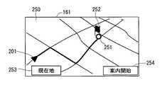
図7は、経路全体画面250を示す図である。経路全体画面250は、図6に示す施設周辺画面240において、探索開始ボタン243が押下された場合に、自車両の現在位置から目的地までの経路を探索した結果を表示する画面である。経路全体画面250では、自車両の現在位置が現在位置マーク201で表示され、目的地が参照符号「251」で示される白丸で表示されている。また目的地251の位置には、目的地251を指し示す目的地マーク252として、旗印のマークが表示されている。 FIG. 7 is a diagram showing the
経路全体画面250では、自車両の現在位置マーク201および目的地251と、それらの周辺の地図と、自車両の現在位置マーク201から目的地251までの経路とが表示される。経路は、太線で表されている。また経路全体画面250は、図2に示す現在位置画面200を表示させるためのタッチスイッチとして、「現在地」と記載された現在地ボタン253を備える。また経路全体画面250は、目的地251までの案内を開始する指示を入力するためのタッチスイッチとして、「案内開始」と記載された案内開始ボタン254を備える。 On the
図8および図9は、本発明の前提となる前提技術における経路案内処理の手順を示すフローチャートである。図8および図9に示すフローチャートの各処理は、コントロールユニット2によって実行される。図8および図9に示すフローチャートの処理は、ナビゲーション装置100の電源が投入されると開始され、ステップST1に移行する。 FIG. 8 and FIG. 9 are flowcharts showing the procedure of route guidance processing in the base technology that is the premise of the present invention. Each process of the flowcharts shown in FIGS. 8 and 9 is executed by the
ステップST1において、コントロールユニット2は、現在地の地図をディスプレイ16に表示させる。たとえば、コントロールユニット2は、現在地の地図として、前述の図2に示す現在位置画面200をディスプレイ16の表示画面161に表示させる。 In step ST1, the
具体的には、まず、自車両の現在位置を表す現在位置データと、地図データとの取得が行われる。すなわち、現在位置検出部5が、GPS受信機3および自立航法センサ4から現在位置データを取得し、検出した自車両の現在位置を、コントロールユニット2に与える。また、情報入力部9が、情報入力部9を構成するHDD、または情報入力部9の挿入部91に挿入されるDVDなどのメディアから、地図データを読み出す。情報入力部9は、読み出した地図データを、コントロールユニット2を介して、地図情報格納部71に格納する。 Specifically, first, current position data representing the current position of the host vehicle and map data are acquired. That is, the current
コントロールユニット2は、地図情報格納部71から地図データを読み出し、現在位置検出部5から与えられる現在位置データに対応する位置に、自車両の位置(以下「自車位置」という)を表す現在位置マーク201を重ね合わせるマッチング処理を行う。このマッチング処理が施された地図データは、コントロールユニット2を介して、表示制御部15に与えられる。 The
表示制御部15は、コントロールユニット2によってマッチング処理が施された地図データに基づいて、描画データを生成し、ディスプレイ16に与える。これによって、前述の図2に示すように、ディスプレイ16に、自車両の現在位置を中心とした地図が表示される。現在地の地図が表示されると、ステップST2に移行する。 The
ステップST2において、コントロールユニット2は、目的地が設定されたか否かを判断する。ステップST2において、目的地が設定されたと判断された場合は、ステップST3に移行し、目的地が設定されていないと判断された場合は、目的地が設定されるまで待機する。 In step ST2, the
利用者は、たとえば、ディスプレイ16に表示されている目的地入力手段としてのタッチスイッチ、または本体に設置されている入力ボタンなどを操作することによって、指示入力部10から、地図データに含まれる地点および施設などの目的地を入力する。たとえば、利用者は、前述の図3〜図5に示す表示画面161に表示されるタッチスイッチを押下することによって、目的地を入力する。 The user operates, for example, a touch switch as a destination input means displayed on the
ステップST2において、目的地が設定されたと判断された場合、施設検索部11は、指示入力部10から入力される情報に基づいて、地点および施設などの目的地入力データをコントロールユニット2に与える。コントロールユニット2は、地図と自車両の現在位置とのマッチング処理の結果と、施設検索部11から与えられる目的地入力データとを、経路計算部12および誘導案内部13に与える。 If it is determined in step ST <b> 2 that the destination has been set, the
次いで、ステップST3において、コントロールユニット2は、前述の図6に示す施設周辺画面240において、探索開始ボタン243が押下されたことを検出したか否かを判断する。ステップST2において、押下が検出されたと判断された場合は、ステップST4に移行し、押下が検出されていないと判断された場合は、押下が検出されるまで待機する。 Next, in step ST3, the
ステップST4において、コントロールユニット2は、経路探索を開始する。具体的には、経路計算部12が、自車両の現在位置から目的地までの経路を探索する処理を実行して、経路を作製する。このようにして経路を作製すると、ステップST5に移行する。 In step ST4, the
ステップST5において、コントロールユニット2は、目的地まで走行可能か否かを判断する。ステップST5において、走行可能と判断された場合は、ステップST8に移行し、走行不可能と判断された場合は、ステップST6に移行する。 In step ST5, the
ステップST6において、コントロールユニット2は、目的地までの経路中に、目的地に到着する前にバッテリを充電可能なバッテリ充電可能地点である到着前充電可能地点を追加し、ステップST7に移行する。 In step ST6, the
ステップST7において、コントロールユニット2は、ステップST6で追加した到着前充電可能地点を含むように、目的地までの経路の再探索を開始する。具体的には、経路計算部12が、自車両の現在位置から目的地までの経路を探索する処理を再度実行して、経路を作製する。このようにして経路を作製すると、ステップST8に移行する。 In step ST7, the
ステップST8において、コントロールユニット2は、目的地までの経路を表示する。具体的には、コントロールユニット2は、自車位置から目的地までの経路案内処理を行うように、誘導案内部13に指示する。誘導案内部13は、コントロールユニット2の指示に基づいて、自車位置から目的地までの誘導案内処理を実施して、経路案内情報を作製する。コントロールユニット2は、経路計算部12から与えられる目的地までの経路と、誘導案内部13から与えられる目的地までの交差点案内図などの誘導用情報とを表示制御部15に与える。表示制御部15は、与えられた経路と誘導用情報とに、ディスプレイ16で表示するための表示処理を施して、ディスプレイ16に与える。これによって、経路と誘導用情報とがディスプレイ16に表示される。 In step ST8, the
ステップST9において、コントロールユニット2は、目的地までの経路案内開始ボタンの押下を検出したか否かを判断する。ステップST9において、押下が検出されたと判断された場合は、ステップST10に移行し、押下が検出されていないと判断された場合は、押下が検出されるまで待機する。 In step ST9, the
ステップST10において、コントロールユニット2は、目的地までの経路案内を開始する。具体的には、コントロールユニット2は、誘導案内部13から与えられる目的地までの誘導用情報のうち、誘導用音声情報を、音声制御部17に与える。音声制御部17は、与えられた誘導用音声情報に、スピーカ18で出力するための音声処理を施して、スピーカ18に与える。これによって、誘導用音声情報が表す音声がスピーカ18から出力される。このようにして、スピーカ18から音声で利用者に経路を誘導案内する。 In step ST10, the
以後は、コントロールユニット2は、車両の進行に連れて変化する環境に対応した案内メッセージを表す誘導用音声情報を順次、音声制御部17に与えてスピーカ18に出力させる。これによって、車両の進行に連れて変化する環境に対応した案内メッセージがスピーカ18から順次出力される。このようにして経路案内を開始すると、ステップST11に移行する。 Thereafter, the
ステップST11において、コントロールユニット2は、目的地に到着したか否かを判断する。ステップST11において、到着したと判断された場合は、ステップST12に移行し、到着していないと判断された場合は、到着したと判断されるまで待機する。ステップST12において、コントロールユニット2は、経路案内を終了し、ステップST1に戻って、前述の処理を繰り返す。 In step ST11, the
このように前提技術では、目的地まで走行できないと判断された場合には、目的地までの経路中に到着前充電可能地点を追加して、利用者に案内するが、目的地に到着した後のバッテリの残量については考慮されていない。したがって、目的地に到着した後に走行不可能となることがある。そこで、本実施の形態では、以下の構成を採用している。 As described above, in the base technology, if it is determined that the vehicle cannot travel to the destination, a pre-arrival chargeable point is added to the route to the destination and the user is guided, but after arriving at the destination The remaining battery capacity is not considered. Therefore, it may become impossible to travel after arriving at the destination. Therefore, in this embodiment, the following configuration is adopted.
図10および図11は、本発明の第1の実施の形態において、ナビゲーション装置100のディスプレイ16の表示画面161に表示される画像の一例を示す図である。図10は、経路全体画面300を示す図である。本実施の形態では、前述の図6に示す施設周辺画面240において、探索開始ボタン243が押下された場合、図10に示す経路全体画面300が表示される。経路全体画面300では、現在位置マーク201、目的地251および目的地マーク252に加えて、到着後充電可能地点301が表示される。到着後充電可能地点301は、目的地への到着後のバッテリ充電可能地点である。経路全体画面300では、目的地251から到着後充電可能地点301までの経路が破線で表示されている。 10 and 11 are diagrams illustrating an example of an image displayed on the
また経路全体画面300は、現在地ボタン253に加えて、目的地251までの経路探索の開始を指示するための目的地経路探索開始ボタン302と、到着後充電可能地点301までの経路探索の開始を指示するための充電地点経路探索開始ボタン303とを備える。 In addition to the
図11は、経路全体画面310を示す図である。図11では、図10に示す経路全体画面300において、充電地点経路探索開始ボタン303が押下された場合に表示される経路全体画面310を示す。経路全体画面310は、到着後充電可能地点301までの経路案内の開始を指示するための案内開始ボタン311を備える。 FIG. 11 is a diagram showing the
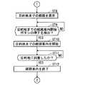
図12〜図17は、本発明の第1の実施の形態における経路案内の処理手順を示すフローチャートである。図12〜図17に示すフローチャートの各処理は、コントロールユニット2によって実行される。図12〜図17に示すフローチャートの処理は、ナビゲーション装置100の電源が投入されると開始され、ステップST21に移行する。 12 to 17 are flowcharts showing a route guidance processing procedure according to the first embodiment of the present invention. Each process of the flowcharts shown in FIGS. 12 to 17 is executed by the
ステップST21〜ステップST23の処理は、前述の図8に示すステップST1〜ステップST3の処理と同様に行われる。すなわち、ステップST21において、自車両を含む現在地の地図がディスプレイ16に表示される。 The processes in steps ST21 to ST23 are performed in the same manner as the processes in steps ST1 to ST3 shown in FIG. That is, in step ST21, a map of the current location including the host vehicle is displayed on the
ステップST22において、目的地が設定されたか否かが判断され、目的地が設定されたと判断されると、ステップST23に移行し、目的地が設定されていないと判断されると、目的地が設定されたと判断されるまで待機する。 In step ST22, it is determined whether or not the destination is set. If it is determined that the destination is set, the process proceeds to step ST23. If it is determined that the destination is not set, the destination is set. Wait until it is determined that it has been done.
ステップST23において、経路探索開始ボタンの押下が検出されたか否かが判断され、押下が検出されたと判断されると、ステップST24に移行し、押下が検出されていないと判断されると、押下が検出されたと判断されるまで待機する。 In step ST23, it is determined whether or not the pressing of the route search start button is detected. If it is determined that the pressing is detected, the process proceeds to step ST24. If it is determined that the pressing is not detected, the pressing is not performed. Wait until it is determined that it has been detected.
本実施の形態では、ステップST24において、コントロールユニット2は、利用者が設定した目的地の後に、到着後充電可能地点を追加する。到着後充電可能地点としては、たとえば、目的地に最も近いバッテリ充電施設が設置された地点、または利用者が以前に入力して保存したバッテリ充電可能地点を追加する。このようにして到着後充電可能地点を追加すると、ステップST25に移行する。 In the present embodiment, in step ST24, the
ステップST25において、コントロールユニット2は、ナビゲーション装置100の外部から与えられる自車両に関する情報(以下「外部車両情報」という)から、バッテリ充電情報として、バッテリ残容量などのEV情報を取得する。 In step ST <b> 25, the
次いで、ステップST26において、ステップST25で追加された到着後充電可能地点までの経路探索を開始する。このようにして経路探索を開始すると、ステップST27に移行する。 Next, in step ST26, a route search to the post-arrival chargeable point added in step ST25 is started. When the route search is thus started, the process proceeds to step ST27.
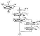
ステップST27において、外部車両情報からバッテリ残容量などのEV情報を考慮して、到着後充電可能地点まで走行可能か否かを判断する。ステップST27において、走行可能と判断された場合は、ステップST30に移行し、走行不可能と判断された場合は、ステップST28に移行する。 In step ST27, it is determined whether or not the vehicle can travel to a chargeable point after arrival in consideration of EV information such as the remaining battery capacity from the external vehicle information. If it is determined in step ST27 that traveling is possible, the process proceeds to step ST30. If it is determined that traveling is not possible, the process proceeds to step ST28.
ステップST27で目的地までの走行が不可能と判断されてステップST28に移行した場合は、ステップST28において、コントロールユニット2は、バッテリ容量などのEV情報および走行情報を取得し、これらを考慮して、目的地を経て到着後充電可能地点まで走行できるように、目的地までの経路中に経由地として到着前充電可能地点を追加する。到着前充電可能地点としては、たとえば、バッテリ充電施設が設置される地点、または利用者が以前に入力して保存したバッテリ充電可能地点が選択される。 When it is determined in step ST27 that it is impossible to travel to the destination and the process proceeds to step ST28, in step ST28, the
ステップST29において、コントロールユニット2は、到着前充電可能地点を追加設定した経路で、到着後充電可能地点までの経路の再探索を開始する。具体的には、誘導案内部13は、自車両の現在位置から目的地までの誘導案内処理を行い、経路案内情報を作製する。 In step ST29, the
ステップST30において、コントロールユニット2は、目的地経由で到着後充電可能地点までの経路をディスプレイ16に表示する。具体的には、コントロールユニット2は、経路計算部12から与えられる目的地までの経路と、誘導案内部13から与えられる目的地までの交差点案内図などの誘導用情報とを、表示制御部15に与える。表示制御部15は、与えられた経路と誘導用情報とに、ディスプレイ16で表示するための表示処理を施して、ディスプレイ16に与え、ディスプレイ16に表示させる。 In step ST30, the
ステップST31において、コントロールユニット2は、到着後充電可能地点までの経路案内開始ボタンの押下を検出したか否かを判断する。ステップST31において、押下を検出したと判断された場合は、ステップST32に移行し、押下を検出していないと判断された場合は、ステップST33に移行する。 In step ST31, the
ステップST32において、コントロールユニット2は、目的地までの経路案内を開始する。具体的には、コントロールユニット2は、誘導案内部13から与えられる目的地までの誘導用情報のうち、誘導用音声情報を音声制御部17に与える。音声制御部17は、与えられた誘導用音声情報に、スピーカ18で出力するための音声処理を施して、スピーカ18に与え、スピーカ18から音声を出力させる。このようにして、利用者に音声によって経路を誘導案内する。以後は、車両の進行に連れて変化する環境に対応した案内メッセージが順次出力される。このようにして、目的地までの経路案内を開始すると、図14に示すステップST35に移行する。 In step ST32, the
ステップST31からステップST33に移行した場合、ステップST33において、コントロールユニット2は、目的地までの経路案内開始ボタンの押下を検出したか否かを判断する。ステップST33において、押下を検出したと判断した場合は、ステップST34に移行し、押下を検出していないと判断した場合は、ステップST31に戻る。 When the process proceeds from step ST31 to step ST33, in step ST33, the
ステップST34において、コントロールユニット2は、ステップST32と同様にして、目的地までの経路案内を開始する。このようにして、目的地までの経路案内を開始すると、図17に示すステップST53に移行する。 In step ST34, the
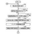
図14に示すステップST35において、コントロールユニット2は、自車両が案内経路を走行しているか否かを判断する。ステップST35において、案内経路を走行していると判断された場合は、図15に示すステップST41に移行し、案内経路を走行していないと判断された場合は、ステップST36に移行する。 In step ST35 shown in FIG. 14, the
ステップST36において、コントロールユニット2は、バッテリ充電情報を取得し、ステップST37に移行する。 In step ST36, the
ステップST37において、コントロールユニット2は、到着後充電可能地点までの経路の再探索を開始する。このようにして、到着後充電可能地点までの経路の再探索を開始すると、ステップST38に移行する。 In step ST37, the
ステップST38において、コントロールユニット2は、ステップST36で取得したバッテリ充電情報に基づいて、到着後充電可能地点まで走行可能か否かを判断する。ステップST38において、走行可能と判断された場合は、図13に示すステップST32に戻り、ステップST37で再探索した経路について、目的地までの経路案内を開始する。ステップST38において、走行不可能と判断された場合は、ステップST39に移行する。 In step ST38, the
ステップST39において、コントロールユニット2は、前述の図13に示すステップST28と同様にして、目的地までの経路中に到着前充電可能地点を追加し、ステップST40に移行する。 In step ST39, the
ステップST40において、コントロールユニット2は、前述の図13に示すステップST29と同様にして、到着前充電可能地点を含むように、到着後充電可能地点までの経路の再探索を開始する。このようにして再探索を開始すると、前述の図13に示すステップST32に戻り、ステップST40で再探索した経路について、目的地までの経路案内を開始する。 In step ST40, the
図15に示すステップST41において、コントロールユニット2は、目的地に到着したか否かを判断する。ステップST41において、目的地に到着したと判断された場合は、ステップST42に移行し、目的地に到着していないと判断された場合は、前述の図14に示すステップST35に戻り、前述の処理を繰返す。 In step ST41 shown in FIG. 15, the
ステップST42において、コントロールユニット2は、電源のオフが指示されたか否かを判断する。ステップST42において、電源のオフが指示されていないと判断された場合は、ステップST43に移行し、電源のオフが指示されたと判断された場合は、ステップST45に移行する。 In step ST42, the
ステップST43において、コントロールユニット2は、表示制御部15を制御して、目的地から到着後充電可能地点までの経路をディスプレイ16に表示し、ステップST44に移行する。 In step ST43, the
ステップST44において、コントロールユニット2は、到着後充電可能地点までの走行が選択されたか否かを判断する。ステップST44において、走行が選択されたと判断された場合は、図16に示すステップST46に移行し、走行が選択されていないと判断された場合は、ステップST45に移行する。 In step ST44, the
ステップST45において、コントロールユニット2は、目的地までの誘導案内を終了する。このようにして誘導案内を終了すると、図12に示すステップST21に戻り、前述の処理を繰返す。 In step ST45, the
図16に示すステップST46において、コントロールユニット2は、目的地から到着後充電可能地点までの経路をディスプレイ16に表示する。これによって、利用者に、次のバッテリ充電可能地点である到着後充電可能地点までの経路を提示し、到着後充電可能地点まで走行するか否かを利用者に判断させる。利用者は、到着後充電可能地点まで走行すると判断した場合、たとえば前述の図11の到着後充電可能地点までの経路を示した経路全体画面310において、案内開始ボタン311を押下することによって、到着後充電可能地点までの経路案内を開始するように指示する。 In step ST46 shown in FIG. 16, the
ステップST47において、コントロールユニット2は、到着後充電可能地点までの経路案内開始ボタンの押下を検出したか否かを判断する。ステップST47において、押下を検出したと判断された場合は、ステップST48に移行し、押下を検出していないと判断された場合は、押下を検出したと判断されるまで待機する。 In step ST47, the
ステップST48において、コントロールユニット2は、到着後充電可能地点までの経路案内を開始する。 In step ST48, the
ステップST49において、コントロールユニット2は、案内経路を走行しているか否かを判断する。ステップST49において、案内経路を走行していると判断された場合は、ステップST51に移行し、案内経路を走行していないと判断された場合は、ステップST50に移行する。 In step ST49, the
ステップST50において、コントロールユニット2は、到着後充電可能地点までの経路の再探索を開始する。このようにして再探索を開始すると、ステップST48に戻り、ステップST50で再探索した到着後充電可能地点までの経路について、経路案内を開始する。 In step ST50, the
ステップST51において、コントロールユニット2は、到着後充電可能地点に到着したか否かを判断する。ステップST51において、到着したと判断された場合は、ステップST52に移行し、到着していないと判断された場合は、ステップST49に戻り、前述の処理を繰返す。 In step ST51, the
ステップST52において、コントロールユニット2は、経路案内を終了して、前述の図12に示すステップST21に戻り、ディスプレイ16に現在地の地図を表示する。すなわち、ディスプレイ16の表示画面161が、現在位置画面200に戻る。 In step ST52, the
前述の図13に示すステップST33において、目的地までの経路案内開始ボタンの押下を検出したと判断されて、ステップST34を経て、図17に示すステップST53に移行した場合、ステップST53において、コントロールユニット2は、案内経路を走行しているか否かを判断する。ステップST53において、案内経路を走行していると判断された場合は、ステップST54に移行し、案内経路を走行していないと判断された場合は、ステップST56に移行する。 If it is determined in step ST33 shown in FIG. 13 that the pressing of the route guidance start button to the destination has been detected, and the process proceeds to step ST53 shown in FIG. 17 through step ST34, the control unit in step ST53. 2 determines whether or not the vehicle is traveling along the guide route. If it is determined in step ST53 that the vehicle is traveling along the guide route, the process proceeds to step ST54. If it is determined that the vehicle is not traveling on the guide route, the process proceeds to step ST56.
ステップST54において、コントロールユニット2は、自車両が目的地に到着したか否かを判断する。ステップST54において、到着したと判断された場合は、ステップST55に移行し、到着していないと判断された場合は、ステップST53に戻り、前述の処理を繰返す。ステップST55において、コントロールユニット2は、経路案内を終了し、前述の図12に示すステップST21に戻り、現在地の地図をディスプレイ16に表示する。 In step ST54, the
ステップST53からステップST56に移行した場合、ステップST56において、コントロールユニット2は、バッテリ充電情報を取得し、ステップST57に移行する。ステップST57において、コントロールユニット2は、目的地までの経路の再探索を開始し、ステップST58に移行する。 When the process proceeds from step ST53 to step ST56, in step ST56, the
ステップST58において、コントロールユニット2は、目的地まで走行可能か否かを判断する。ステップST58において、走行可能と判断された場合は、図13に示すステップST34に戻り、目的地までの経路案内を継続する。ステップST58において、走行不可能と判断された場合は、ステップST59に移行する。 In step ST58, the
ステップST59において、コントロールユニット2は、目的地までの経路中に、到着前充電可能地点を追加し、ステップST60に移行する。 In step ST59, the
ステップST60において、コントロールユニット2は、ステップST59で追加した到着前充電可能地点を含むように、目的地までの経路の再探索を開始する。このようにして再探索を開始すると、図13に示すステップST34に戻り、ステップST60で再探索した目的地までの経路について、経路案内を開始する。 In step ST60, the
以上のように本実施の形態によれば、現在位置検出部5によって取得される現在位置から、指示入力部10によって入力された目的地を経て、到着後充電可能地点に至る経路が、経路計算部12によって探索される。これによって、目的地に到着する前に、予め、到着後充電可能地点を把握することができる。したがって、たとえば、目的地に到着した後に自車両が走行不可能とならないような対策を予め講じることができる。 As described above, according to the present embodiment, the route from the current position acquired by the current
また本実施の形態では、EV情報入力部19によって、自車両のバッテリの充電量に関するバッテリ充電情報が取得される。コントロールユニット2は、取得されたバッテリ充電情報に基づいて、現在位置から目的地を経由して到着後充電可能地点まで走行可能であるか否かを判断する。 Moreover, in this Embodiment, the battery charge information regarding the charge amount of the battery of the own vehicle is acquired by the EV
これによって、目的地に到着する前に、現在位置から目的地を経由して到着後充電可能地点まで走行可能であるか否かを判断することができる。したがって、たとえば、目的地に到着する前に、自車両が目的地から到着後充電可能地点まで走行可能となるような対策を講じることができる。 Thereby, before arriving at the destination, it is possible to determine whether or not it is possible to travel from the current position via the destination to the chargeable point after arrival. Therefore, for example, it is possible to take measures so that the host vehicle can travel from the destination to a chargeable point after arrival before arriving at the destination.
また本実施の形態では、コントロールユニット2によって、到着前充電可能地点まで走行可能であると判断されると、経路計算部12によって探索された現在位置から目的地を経由して到着後充電可能地点に至る経路が、表示制御部15によってディスプレイ16に出力される。 In this embodiment, when it is determined by the
これによって、現在位置から目的地を経由して到着後充電可能地点まで走行可能であることを利用者に提示することができる。また、目的地に到着する前に、到着後充電可能地点を利用者に提示することができる。したがって、利用者は、自車両が走行不可能となることを心配することなく、自車両を走行させることができる。 Thereby, it can be shown to the user that the vehicle can travel from the current position to the chargeable point after arrival via the destination. In addition, before arrival at the destination, a chargeable point after arrival can be presented to the user. Therefore, the user can drive the host vehicle without worrying that the host vehicle cannot run.
また本実施の形態では、コントロールユニット2によって、到着後充電可能地点まで走行不可能であると判断されると、経路計算部12によって、現在位置から目的地までの間に到着前充電可能地点を含む経路が再探索される。表示制御部15は、再探索された経路をディスプレイ16に出力する。 In the present embodiment, when the
これによって、目的地に到着する前に、自車両が到着後充電可能地点まで走行できないことを利用者に提示することができる。また、目的地に到着する前に、現在位置から目的地までの間の到着前充電可能地点を利用者に提示することができる。これによって、到着前充電可能地点で充電するように利用者に促すことができるので、自車両が到着後充電可能地点まで走行できなくなることを防ぐことができる。 Thus, before the vehicle arrives at the destination, it can be shown to the user that the vehicle cannot travel to the rechargeable point after arrival. In addition, before arrival at the destination, a pre-arrival chargeable point between the current position and the destination can be presented to the user. As a result, the user can be prompted to charge at the pre-arrival chargeable point, so that the host vehicle can be prevented from traveling to the chargeable point after arrival.
また本実施の形態では、誘導案内部13によって、表示制御部15および音声制御部17を用いて、経路計算部12で探索された経路が案内される。これによって、現在位置から目的地を経由して到着後充電可能地点までの経路を利用者に案内することができる。したがって、利用者の利便性を向上させることができる。 Further, in the present embodiment, the route searched by the
また本実施の形態では、指示入力部10は、到着後充電可能地点の候補となる地点を入力可能に構成されるので、利用者によって、到着後充電可能地点の候補となる地点を入力することができる。これによって、たとえば利用者の自宅または友人宅など、公共の施設でない個人の施設を到着後充電可能地点として含む経路を探索することができる。したがって、利用者の利便性を向上させることができる。 Further, in this embodiment, the
以上に述べた本実施の形態では、図15に示すステップST42において、電源のオフが指示されたと判断された場合は、ステップST45に移行して、目的地から到着後充電可能地点までの経路案内を行わずに、経路案内を終了している。 In the present embodiment described above, if it is determined in step ST42 shown in FIG. 15 that the power-off is instructed, the process proceeds to step ST45, and the route guidance from the destination to the chargeable point after arrival is provided. The route guidance is finished without performing.
これに限定されず、たとえば、利用者が自車両およびナビゲーション装置100の電源を切断して、目的地を訪問した後に、目的地から到着後充電可能地点までの経路案内を行うようにしてもよい。この場合、電源を切断した後に、到着後充電可能地点までの経路を、メモリ、たとえば情報格納部7に記憶させておく。 However, the present invention is not limited to this. For example, after the user turns off the power of the vehicle and the
そして、電源が再投入されたときに、ステップST43において、到着後充電可能地点まで走行するか否かの判断を利用者に仰ぐメッセージと共に、到着後充電可能地点までの経路を表示する。そして、ステップST44において、到着後充電可能地点までの走行が選択されたと判断されると、ステップST46に移行し、経路案内を開始するようにしてもよい。 When the power is turned on again, in step ST43, a route to the chargeable point after arrival is displayed together with a message asking the user whether or not to travel to the chargeable point after arrival. Then, when it is determined in step ST44 that traveling to a chargeable point after arrival has been selected, the process may move to step ST46 to start route guidance.
<第2の実施の形態>
本発明の第2の実施の形態のナビゲーション装置は、経路案内の処理手順が異なること以外は、第1の実施の形態におけるナビゲーション装置100と同様の構成を有する。したがって、第2の実施の形態のナビゲーション装置において、第1の実施の形態と同一の構成については、同一の参照符号を付して、図示および説明を省略する。<Second Embodiment>
The navigation device of the second embodiment of the present invention has the same configuration as the
前述の第1の実施の形態では、ステップST30において、目的地経由で到着後充電可能地点までの経路を表示する。そして、ステップST31で到着後充電可能地点までの経路案内開始ボタンの押下が検出されたと判断された場合、ステップST32〜ステップST40で目的地までの経路を案内し、ステップST41で目的地に到着したと判断された後に、ステップST43において、到着後充電可能地点までの経路を表示する。そして、ステップST44で到着後充電可能地点までの走行が選択されたと判断された場合、ステップST46〜ステップST52で、到着後充電可能地点までの経路を案内する。 In the first embodiment described above, in step ST30, the route to the chargeable point after arrival via the destination is displayed. If it is determined in step ST31 that the route guidance start button has been pressed down to the chargeable point after arrival, the route to the destination is guided in steps ST32 to ST40, and the destination is reached in step ST41. In step ST43, the route to the chargeable point after arrival is displayed. If it is determined in step ST44 that traveling to a chargeable point after arrival is selected, a route to the chargeable point after arrival is guided in steps ST46 to ST52.
これに対し、本実施の形態では、以下のようにして経路探索処理が行われる。図18〜図22は、本発明の第2の実施の形態における経路案内の処理手順を示すフローチャートである。図18〜図22に示すフローチャートの各処理は、コントロールユニット2によって実行される。図18〜図22に示すフローチャートにおいて、前述の図12〜図17に示すフローチャートと同一のステップについては、同一のステップ番号を付して、説明を省略する。図18〜図22に示すフローチャートの処理は、ナビゲーション装置100の電源が投入されると開始され、ステップST21に移行する。 On the other hand, in this embodiment, the route search process is performed as follows. 18 to 22 are flowcharts showing a route guidance processing procedure according to the second embodiment of the present invention. Each process of the flowcharts shown in FIGS. 18 to 22 is executed by the
前述の第1の実施の形態と同様にして、ステップST21〜ステップST26の処理が行われ、図19に示すステップST27に移行する。本実施の形態では、ステップST27において、到着後充電可能地点まで走行可能と判断された場合は、ステップST71に移行し、到着後充電可能地点まで走行不可能と判断された場合は、ステップST28に移行する。また、ステップST28およびステップST29の処理が終了した後は、ステップST71に移行する。 In the same manner as in the first embodiment described above, the processes in steps ST21 to ST26 are performed, and the process proceeds to step ST27 shown in FIG. In the present embodiment, if it is determined in step ST27 that the vehicle can travel to a chargeable point after arrival, the process proceeds to step ST71. If it is determined that the vehicle cannot travel to a chargeable point after arrival, the process proceeds to step ST28. Transition. Moreover, after the processing of step ST28 and step ST29 is completed, the process proceeds to step ST71.
ステップST71において、コントロールユニット2は、目的地までの経路をディスプレイ16に表示する。このようにして目的地までの経路をディスプレイ16に表示すると、ステップST72に移行する。 In step ST71, the
ステップST72において、コントロールユニット2は、目的地までの経路案内開始ボタンの押下を検出したか否かを判断する。ステップST72において、検出したと判断された場合は、ステップST32に移行し、検出していないと判断された場合は、検出したと判断されるまで待機する。その後は、第1の実施の形態と同様にして、ステップST32の処理が行われ、図20に示すステップST35に移行する。 In step ST72, the
本実施の形態では、ステップST35において、案内経路を走行していると判断された場合は、図21に示すステップST73に移行する。ステップST35において、案内経路を走行していないと判断された場合は、第1の実施の形態と同様に、ステップST36に移行し、ステップST36〜ステップST40の処理が行われた後、図19に示すステップST32に戻る。 In the present embodiment, if it is determined in step ST35 that the vehicle is traveling along the guide route, the process proceeds to step ST73 shown in FIG. If it is determined in step ST35 that the vehicle is not traveling on the guide route, the process proceeds to step ST36 and the processes in steps ST36 to ST40 are performed as in the first embodiment. It returns to step ST32 shown.
図21に示すステップST73において、コントロールユニット2は、目的地に到着したか否かを判断する。ステップST73において、目的地に到着したと判断された場合は、ステップST43に移行し、目的地に到着していないと判断された場合は、図20に示すステップST35に戻り、前述の処理を繰返す。ステップST43以降の処理は、前述の第1の実施の形態と同様に行われる。 In step ST73 shown in FIG. 21, the
以上のように本実施の形態では、まず、ステップST71において、目的地までの経路を表示し、ステップST32〜ステップST40で、目的地までの経路を案内する。そして、ステップST73で目的地に到着したと判断された後に、ステップST43において、到着後充電可能地点までの経路を表示し、ステップST46〜ステップST52で、到着後充電可能地点までの経路を案内する。 As described above, in this embodiment, first, in step ST71, the route to the destination is displayed, and the route to the destination is guided in steps ST32 to ST40. Then, after it is determined in step ST73 that the vehicle has arrived at the destination, in step ST43, the route to the chargeable point after arrival is displayed, and in step ST46 to step ST52, the route to the chargeable point after arrival is guided. .
このように、目的地までの経路と、到着後充電可能地点までの経路とを、順次表示して案内するようにしても、前述の第1の実施の形態と同様の効果を得ることができる。たとえば、本実施の形態においても、現在位置検出部5によって取得される現在位置から、指示入力部10によって入力された目的地を経て、到着後充電可能地点に至る経路が、経路計算部12によって探索されるので、目的地に到着する前に、予め、到着後充電可能地点を把握することができる。したがって、たとえば、目的地に到着した後に自車両が走行不可能とならないような対策を予め講じることができる。 As described above, even when the route to the destination and the route to the chargeable point after arrival are sequentially displayed and guided, the same effect as in the first embodiment can be obtained. . For example, also in the present embodiment, a route from the current position acquired by the current
また本実施の形態では、目的地に到着するまでは、到着後充電可能地点までの経路はディスプレイ16に表示されない。これによって、利用者は、目的地までの経路案内を行うのか、到着後充電可能地点までの経路案内を行うのかを、予め選択する必要がない。したがって、目的地に到着した後に自車両が走行不可能となることを防ぎつつ、利用者の操作が煩雑になることを防ぐことができる。 In the present embodiment, the route to the chargeable point after arrival is not displayed on the
以上に述べた第1および第2の実施の形態では、ナビゲーション装置100において、代表的な各機能を実行する手段をそれぞれコントロールユニット2とは独立して説明している。これらの各機能を実行する手段、たとえば現在位置検出部5、情報更新部8、施設検索部11、経路計算部12、誘導案内部13、情報描画部14、表示制御部15および音声制御部17のいずれか1つまたは複数は、コントロールユニット2に内蔵されてもよい。また、これらの機能をマイクロコンピュータで達成するようにしてもよい。また本実施の形態では、情報描画部14と表示制御部15とは、別個に設けられるが、一体に構成されてもよい。 In the first and second embodiments described above, the means for executing each representative function in the
また本実施の形態では、ナビゲーション装置100は、地図情報格納部71に格納された地図情報に基づいて動作する独立方式のナビゲーション装置である。ナビゲーション装置100は、これに限定されない。ナビゲーション装置100は、必要なときに必要な範囲の地図情報を通信によって取得し、これをDRAM(Dynamic Random Access Memory)などで構成される内部のワークメモリ装置に一時的に記憶して使用する通信方式のナビゲーション装置でもよい。 In the present embodiment, the
また本実施の形態では、情報格納部7は、HDD装置によって実現される。情報格納部7は、これに限定されず、たとえば、半導体素子を用いたメモリ装置によって実現されてもよい。 In the present embodiment, the
また本実施の形態では、情報入力部9は、挿入部91に挿入されたメディアなどによって外部から与えられる情報を、コントロールユニット2を介して情報格納部7に格納するように構成される。情報入力部9は、これに限定されず、外部から与えられる情報を情報入力部9自体に格納して、情報格納部7として機能するように構成されてもよい。この場合、情報格納部7は設けなくてよい。 In the present embodiment, the
また情報入力部9は、USB(Universal Serial Bus)などの接続端子として構成されてもよい。この場合、接続端子である情報入力部9と、情報を含む携帯型のメディアとは、直接または有線で接続される。 The
接続端子として構成される情報入力部9に接続される携帯型のメディアは、携帯型の楽曲プレイヤーであってもよく、その機能を搭載した電子機器であってもよい。また、携帯電話機または携帯型タブレット端末などの携帯型情報通信機器であってもよい。携帯型のメディアと情報入力部9とは、有線で接続されていてもよいが、物理的に接続されている必要はなく、無線で情報の授受を行うように構成されてもよい。ここで「無線」とは、有線に対して、線で接続されていないものという意味であり、その情報授受の方式、たとえば電波、光などのいずれを用いた方式かは問わない。 The portable medium connected to the
また情報入力部9は、別途設置された情報センターと情報の授受を行う通信機器を内蔵するように構成されてもよい。この場合、情報入力部9は、内蔵する通信機器によって、たとえば、前述の地図情報およびAV情報のいずれか一方の情報あるいは他の情報などを授受する。情報入力部9は、この通信機器を内蔵する代わりに、前述の携帯型情報通信機器を用いるものであってもよい。 Further, the
また本実施の形態では、経路計算部12は、推奨経路として、1つの経路を提示するように構成される。経路計算部12は、これに限定されず、推奨経路として、複数の経路を提示するように構成されてもよい。この場合に提示される複数の経路は、必ずしも全ての経路が最短経路ではないこともあるが、ある程度の許容量をもって提示するものとする。これは他の選択肢の経路である最速経路、安価経路、低燃費経路、標準経路についても同様である。 In the present embodiment, the
ナビゲーション装置100は、AV情報出力用のスピーカ18とは別に、誘導用情報を出力するためのスピーカ18を内蔵していてもよい。 The
本発明は、その発明の範囲内において、前述の各実施の形態を自由に組み合わせることが可能であり、また各実施の形態の任意の構成要素を適宜、変形または省略することが可能である。 The present invention can be freely combined with the above-described embodiments within the scope of the invention, and arbitrary constituent elements of the embodiments can be appropriately modified or omitted.
この発明は詳細に説明されたが、上記した説明は、全ての局面において、例示であって、この発明がそれに限定されるものではない。例示されていない無数の変形例が、この発明の範囲から外れることなく想定され得るものと解される。 Although the present invention has been described in detail, the above description is illustrative in all aspects, and the present invention is not limited thereto. It is understood that countless variations that are not illustrated can be envisaged without departing from the scope of the present invention.
1 ナビゲーション装置本体、2 コントロールユニット、3 GPS受信機、4 自立航法センサ、5 現在位置検出部、6 交通情報送受信部、7 情報格納部、8 情報更新部、9 情報入力部、10 指示入力部、11 施設検索部、12 経路計算部、13 誘導案内部、14 情報描画部、15 表示制御部、16 ディスプレイ、17 音声制御部、18 スピーカ、19 EV情報入力部、100 ナビゲーション装置。 DESCRIPTION OF
Claims (11)
Translated fromJapanese前記電気自動車の現在位置を取得する現在位置取得手段と、
前記電気自動車のバッテリの充電量に関するバッテリ充電情報を取得する情報取得手段と、
目的地が入力される入力手段と、
前記現在位置取得手段によって取得される前記電気自動車の現在位置から、前記入力手段によって入力された目的地を経て、前記目的地への到着後に前記電気自動車のバッテリを充電可能な到着後充電可能地点に至る経路を探索する経路探索手段と、
前記経路探索手段で探索された経路を走行しているか否かを判断する判断手段とを備え、
前記経路探索手段は、前記判断手段によって前記経路を走行していないと判断されると、前記到着後充電可能地点に至る経路を再探索し、
前記判断手段は、前記経路を走行していないと判断した場合に前記情報取得手段によって取得される前記バッテリ充電情報に基づいて、前記経路探索手段で再探索された経路の前記到着後充電可能地点に至るまでの走行が可能か否かを判断することを特徴とするナビゲーション装置。A navigation device mounted on an electric vehicle,
Current position acquisition means for acquiring a current position of theelectric vehicle ;
Information acquisition means for acquiring battery charge information relating to the charge amount of the battery of the electric vehicle;
An input means for inputting the destination;
A post-arrival chargeable point where the battery of the electric vehicle can be charged after arriving at the destination fromthe current position of theelectric vehicle acquired by the current position acquisition unit via the destination input by the input unit and route searching means for searching for a routeto,
Determination means for determining whether or not the route searched by the route search means is running,
The route searching means, when it is determined by the determining means that the route is not traveling, re-searches the route to the chargeable point after the arrival,
When the determination means determines that the vehicle is not traveling on the route, the post-arrival chargeable point of the route re-searched by the route search means based on the battery charging information acquired by the information acquisition means navigation apparatus characterized thatyou determine can whether the running up to.
前記電気自動車の現在位置を取得する現在位置取得手段と、
目的地を含む利用者からの指示が入力される入力手段と、
前記現在位置取得手段によって取得される前記電気自動車の現在位置から、前記入力手段によって入力された目的地を経て、前記目的地への到着後に前記電気自動車のバッテリを充電可能な到着後充電可能地点に至る経路を探索する経路探索手段と、
前記入力手段で入力された利用者からの指示に基づいて、前記現在位置から前記到着後充電可能地点までの経路案内および前記現在位置から前記目的地までの経路案内のいずれの経路案内を開始するかを判断する判断手段とを備えることを特徴とするナビゲーション装置。A navigation device mounted on an electric vehicle,
Current position obtaining means for obtaining acurrent position of said electric vehicle,
An input means for inputting instructions from the user including the destination;
A post-arrival chargeable point where the battery of the electric vehicle can be charged after arriving at the destination from the current position of the electric vehicle acquired by the current position acquisition unit via the destination input by the input unit Route search means for searching for a route to
On the basis of aninstruction from the user, which is input by theinput means,any of the route guidance of the route guidance of thefrom the route guidance and the current position tothe current position oret al before Symbol after arrival can be charged pointto the destination features and toLuna navigation device further comprising a determining means for determiningwhether to start.
前記電気自動車の現在位置を取得する現在位置取得手段と、
目的地が入力される入力手段と、
前記現在位置取得手段によって取得される前記電気自動車の現在位置から、前記入力手段によって入力された目的地を経て、前記目的地への到着後に前記電気自動車のバッテリを充電可能な到着後充電可能地点に至る経路を探索する経路探索手段と、
前記電気自動車が前記目的地に到着したか否かを判断する判断手段とを備え、
前記判断手段は、前記電気自動車が前記目的地に到着していないと判断した場合は、前記現在位置から前記目的地までの経路を出力手段で表示させ、前記電気自動車が前記目的地に到着したと判断した場合には、前記目的地から前記到着後充電可能地点までの経路を前記出力手段で表示させることを特徴とするナビゲーション装置。A navigation device mounted on an electric vehicle,
Current position acquisition means for acquiring a current position of the electric vehicle;
An input means for inputting the destination;
A post-arrival chargeable point where the battery of the electric vehicle can be charged after arriving at the destination from the current position of the electric vehicle acquired by the current position acquisition unit via the destination input by the input unit Route search means for searching for a route to
Determining means for determining whether or not the electric vehicle has arrived at the destination;
When the determination means determines that the electric vehicle has not arrived at the destination, the route from the current position to the destination is displayed on the output means, and the electric vehicle has arrived at the destination. and when determining the characteristics and toLuna navigation device Rukototo display a routefrom the destinationto the site allowing charging after the arrivalat said output means.
前記判断手段は、前記情報取得手段によって取得される前記バッテリ充電情報に基づいて、前記現在位置から前記目的地を経由して前記到着後充電可能地点まで走行可能であるか否かを判断することを特徴とする請求項2または3に記載のナビゲーション装置。Comprising information acquisition means for acquiring battery charge information relating to the charge amount of the battery of the electric vehicle,
The determining means, based on the battery charge information acquired by the information acquisition means, whereinyou determine whether or not it is possible to travel fromthe current positionto thesite allowing charging after the arrival via the destination The navigation apparatus according to claim 2or 3 , wherein
前記出力手段は、前記経路探索手段によって経路が再探索されると、再探索された経路を出力することを特徴とする請求項5に記載のナビゲーション装置。Theroute search means, when it isdetermined by the determination means that the vehicle cannot travel to the chargeable point after arrival, the battery of the electric vehicle can be charged from the current position to the destination before arrival. Including a chargeable point, re-searching a route from the current position to the prechargeable chargeable point and the destination to the chargeable point after arrival in order,
Said output means, said when the route searching means route is re-searched, the navigation device according to claim5, wherein alsobe output fromthe re-searched route.
情報取得手段が、前記電気自動車のバッテリの充電量に関するバッテリ充電情報を取得し、The information acquisition means acquires battery charge information related to a charge amount of the battery of the electric vehicle,
経路探索手段が、前記現在位置取得手段によって取得される前記電気自動車の現在位置から、入力手段によって入力された目的地を経て、前記目的地への到着後に前記電気自動車のバッテリを充電可能な到着後充電可能地点に至る経路を探索し、An arrival capable of charging the battery of the electric vehicle after arriving at the destination from the current position of the electric vehicle acquired by the current position acquisition unit through the destination input by the input unit from the current position acquired by the current position acquisition unit Explore the route to the point where you can recharge,
判断手段が、前記経路探索手段で探索された経路を走行しているか否かを判断し、The judging means judges whether or not it is traveling on the route searched by the route searching means,
前記判断手段によって前記経路を走行していないと判断されると、前記経路探索手段が、前記到着後充電可能地点に至る経路を再探索し、When it is determined by the determination means that the route is not being traveled, the route search means re-searches for a route to the chargeable point after arrival,
前記判断手段が、前記経路を走行していないと判断した場合に前記情報取得手段によって取得される前記バッテリ充電情報に基づいて、前記経路探索手段で再探索された経路の前記到着後充電可能地点に至るまでの走行が可能か否かを判断することを特徴とするナビゲーション方法。The post-arrival chargeable point of the route re-searched by the route search unit based on the battery charging information acquired by the information acquisition unit when the determination unit determines that the route is not traveling A navigation method characterized in that it is determined whether or not traveling up to is possible.
経路探索手段が、前記現在位置取得手段によって取得される前記電気自動車の現在位置から、目的地を含む利用者からの指示が入力される入力手段から入力された目的地を経て、前記目的地への到着後に前記電気自動車のバッテリを充電可能な到着後充電可能地点に至る経路を探索し、The route search means, from the current position of the electric vehicle acquired by the current position acquisition means, to the destination through the input means from the input means to which an instruction from the user including the destination is input Search for a route to a chargeable point after arrival that can charge the battery of the electric vehicle after arrival of
判断手段が、前記入力手段で入力された利用者からの指示に基づいて、前記現在位置から前記到着後充電可能地点までの経路案内および前記現在位置から前記目的地までの経路案内のいずれの経路案内を開始するかを判断することを特徴とするナビゲーション方法。Based on the instruction from the user input by the input means, the determination means is either route guidance from the current position to the post-arrival chargeable point or route guidance from the current position to the destination. A navigation method characterized by determining whether to start guidance.
経路探索手段が、前記現在位置取得手段によって取得される前記電気自動車の現在位置から、入力手段によって入力された目的地を経て、前記目的地への到着後に前記電気自動車のバッテリを充電可能な到着後充電可能地点に至る経路を探索し、An arrival capable of charging the battery of the electric vehicle after arriving at the destination from the current position of the electric vehicle acquired by the current position acquisition unit through the destination input by the input unit from the current position acquired by the current position acquisition unit Explore the route to the point where you can recharge,
判断手段が、前記電気自動車が前記目的地に到着したか否かを判断し、前記電気自動車が前記目的地に到着していないと判断した場合は、前記現在位置から前記目的地までの経路を出力手段で表示させ、前記電気自動車が前記目的地に到着したと判断した場合には、前記目的地から前記到着後充電可能地点までの経路を前記出力手段で表示させることを特徴とするナビゲーション方法。The determination means determines whether or not the electric vehicle has arrived at the destination, and determines that the route from the current position to the destination is determined when the electric vehicle has not arrived at the destination. A navigation method characterized by displaying on the output means and displaying on the output means a route from the destination to the rechargeable point after arrival when it is determined that the electric vehicle has arrived at the destination. .
Applications Claiming Priority (1)
| Application Number | Priority Date | Filing Date | Title |
|---|---|---|---|
| PCT/JP2012/058371WO2013145214A1 (en) | 2012-03-29 | 2012-03-29 | Navigation device |
Related Child Applications (1)
| Application Number | Title | Priority Date | Filing Date |
|---|---|---|---|
| JP2016167492ADivisionJP2016206209A (en) | 2016-08-30 | 2016-08-30 | Navigation device and navigation method |
Publications (2)
| Publication Number | Publication Date |
|---|---|
| JPWO2013145214A1 JPWO2013145214A1 (en) | 2015-08-03 |
| JP6000335B2true JP6000335B2 (en) | 2016-09-28 |
Family
ID=49258578
Family Applications (1)
| Application Number | Title | Priority Date | Filing Date |
|---|---|---|---|
| JP2014507180AExpired - Fee RelatedJP6000335B2 (en) | 2012-03-29 | 2012-03-29 | Navigation device and navigation method |
Country Status (5)
| Country | Link |
|---|---|
| US (1) | US20150073636A1 (en) |
| JP (1) | JP6000335B2 (en) |
| CN (2) | CN106855416A (en) |
| DE (1) | DE112012006128T5 (en) |
| WO (1) | WO2013145214A1 (en) |
Families Citing this family (21)
| Publication number | Priority date | Publication date | Assignee | Title |
|---|---|---|---|---|
| US8655586B2 (en)* | 2011-12-28 | 2014-02-18 | Toyota Motor Engineering & Manufacturing North America, Inc. | Intelligent range map for an electric vehicle |
| EP3091336B1 (en) | 2014-03-06 | 2021-05-26 | Mitsubishi Heavy Industries, Ltd. | Device for providing electric-moving-body information and method for providing electric-moving-body information |
| DE102014205341A1 (en)* | 2014-03-21 | 2015-09-24 | Volkswagen Aktiengesellschaft | Display method for a vehicle |
| US10150375B2 (en)* | 2014-04-18 | 2018-12-11 | Hyundai America Technical Center, Inc. | Method for pairing wireless charging system to vehicle |
| US9658076B2 (en)* | 2014-10-06 | 2017-05-23 | Ford Global Technologies, Llc | Vehicle and electric bicycle charge monitoring interface |
| CN106160056B (en)* | 2015-04-21 | 2020-10-27 | 日立(中国)研究开发有限公司 | Driving path planning method for electric automobile and vehicle-mounted device |
| KR20170069092A (en)* | 2015-12-10 | 2017-06-20 | 현대자동차주식회사 | Audio video navigation device and method for providing charging station information using the audio video navigation device |
| US10190882B2 (en)* | 2015-12-17 | 2019-01-29 | Jaguar Land Rover Limited | System and method to facilitate having adequate vehicle power |
| JP6789738B2 (en)* | 2016-09-08 | 2020-11-25 | 株式会社 ミックウェア | Information processing device |
| GB2565532B (en) | 2017-08-04 | 2020-06-24 | Jaguar Land Rover Ltd | Apparatus and method for indicating residual driving range |
| DE102017213984A1 (en)* | 2017-08-10 | 2019-02-14 | Bayerische Motoren Werke Aktiengesellschaft | Method for operating a navigation device for a motor vehicle |
| DE102017216127A1 (en)* | 2017-09-13 | 2019-03-14 | Audi Ag | Method for providing a communication connection between a stationary electrical charging station and a motor vehicle and control device and charging system |
| DE102017216478A1 (en)* | 2017-09-18 | 2019-03-21 | Bayerische Motoren Werke Aktiengesellschaft | A method for automatically requesting a charging vehicle for battery electric locomotion means to minimize charge-related downtime |
| JP7069861B2 (en) | 2018-03-12 | 2022-05-18 | トヨタ自動車株式会社 | Vehicle controls and automobiles |
| GB2572962A (en)* | 2018-04-16 | 2019-10-23 | Morgan Brown Consultancy Ltd | Vehicle Routing |
| JP7099350B2 (en)* | 2019-02-08 | 2022-07-12 | トヨタ自動車株式会社 | Alarm device for electric vehicles |
| CN113632151B (en)* | 2019-03-25 | 2023-06-27 | 本田技研工业株式会社 | Information providing system and information providing method |
| JP7182090B2 (en)* | 2019-04-05 | 2022-12-02 | 矢崎総業株式会社 | Charging service system and server device |
| US11609571B2 (en)* | 2020-02-14 | 2023-03-21 | Ford Global Technologies, Llc | Optimized recharging of autonomous vehicles |
| GB2614337A (en)* | 2021-11-04 | 2023-07-05 | Grid Smarter Cities Ltd | A method for booking an electrical vehicle charging station and a method of managing electrical vehicle battery charging at a commercial parking location |
| GB2628613A (en)* | 2023-03-30 | 2024-10-02 | Jaguar Land Rover Ltd | Vehicle routing |
Family Cites Families (15)
| Publication number | Priority date | Publication date | Assignee | Title |
|---|---|---|---|---|
| US5487002A (en)* | 1992-12-31 | 1996-01-23 | Amerigon, Inc. | Energy management system for vehicles having limited energy storage |
| JP3264123B2 (en)* | 1995-03-06 | 2002-03-11 | 三菱自動車工業株式会社 | Navigation system for hybrid electric vehicles |
| DE19519107C1 (en)* | 1995-05-24 | 1996-04-04 | Daimler Benz Ag | Travel route guidance device for electric vehicle |
| US5922042A (en)* | 1996-09-30 | 1999-07-13 | Visteon Technologies, Llc | Automatic resumption of route guidance in vehicle navigation system |
| JP2001215124A (en)* | 2000-02-03 | 2001-08-10 | Fujitsu Ten Ltd | Navigation device, facility data memory media, and facility data supplying data |
| US6591185B1 (en)* | 2002-02-11 | 2003-07-08 | Visteon Global Technologies, Inc. | Method for determination of fuel usage for a vehicle in a vehicle navigation system |
| US6909968B2 (en)* | 2002-11-30 | 2005-06-21 | Alpine Electronics, Inc. | Arrival detection method for navigation system |
| JP4437816B2 (en)* | 2004-03-26 | 2010-03-24 | パイオニア株式会社 | Navigation device, route search method, route search program, and computer-readable recording medium |
| JP2006184105A (en)* | 2004-12-27 | 2006-07-13 | Aisin Aw Co Ltd | Navigation apparatus |
| JP4665873B2 (en)* | 2005-12-20 | 2011-04-06 | 日産自動車株式会社 | Route setting apparatus and route setting method |
| JP2008039547A (en)* | 2006-08-04 | 2008-02-21 | Matsushita Electric Ind Co Ltd | Guide device |
| EP2323866A2 (en)* | 2008-09-19 | 2011-05-25 | Better Place GmbH | System and method for operating an electric vehicle |
| WO2010137307A1 (en)* | 2009-05-26 | 2010-12-02 | 日立オートモティブシステムズ株式会社 | Vehicle operation support system and vehicle operation support method |
| JP4975075B2 (en)* | 2009-09-30 | 2012-07-11 | クラリオン株式会社 | Navigation device and route calculation method |
| US8583304B2 (en)* | 2011-03-30 | 2013-11-12 | Honda Motor Co., Ltd. | System and method for precise state of charge management |
- 2012
- 2012-03-29CNCN201611242179.7Apatent/CN106855416A/enactivePending
- 2012-03-29WOPCT/JP2012/058371patent/WO2013145214A1/enactiveApplication Filing
- 2012-03-29JPJP2014507180Apatent/JP6000335B2/ennot_activeExpired - Fee Related
- 2012-03-29USUS14/389,264patent/US20150073636A1/ennot_activeAbandoned
- 2012-03-29CNCN201280072034.0Apatent/CN104220841A/enactivePending
- 2012-03-29DEDE112012006128.4Tpatent/DE112012006128T5/ennot_activeWithdrawn
Also Published As
| Publication number | Publication date |
|---|---|
| DE112012006128T5 (en) | 2014-12-18 |
| JPWO2013145214A1 (en) | 2015-08-03 |
| CN106855416A (en) | 2017-06-16 |
| US20150073636A1 (en) | 2015-03-12 |
| WO2013145214A1 (en) | 2013-10-03 |
| CN104220841A (en) | 2014-12-17 |
Similar Documents
| Publication | Publication Date | Title |
|---|---|---|
| JP6000335B2 (en) | Navigation device and navigation method | |
| US8872675B2 (en) | Vehicular travel guidance device, vehicular travel guidance method, and computer program | |
| JP5963879B2 (en) | Navigation device | |
| CN102818574B (en) | Route calculation equipment | |
| US8855842B2 (en) | Vehicular charging facility guidance device, vehicular charging facility guidance method, and computer program | |
| JP4513826B2 (en) | Route display device and route display system | |
| US8452642B2 (en) | Navigation device and method for providing information on parking area | |
| JP5300610B2 (en) | Navigation device, facility search method, and facility search program | |
| JP2001215124A (en) | Navigation device, facility data memory media, and facility data supplying data | |
| JP2012103141A (en) | Navigation device and route finding system | |
| TW200949281A (en) | Portable navigation device, portable electronic communications apparatus, and method of generating radio data system information therefor | |
| WO2007026447A1 (en) | In-vehicle device, portable terminal, and guidance information providing system using them | |
| JP6324196B2 (en) | Information processing apparatus, information processing method, and information processing system | |
| JP2011164050A (en) | In-vehicle navigation device and method of offering information about charging stand | |
| JP2010190594A (en) | Navigation apparatus and electronic instrument equipped with navigation function | |
| JP2012132817A (en) | Navigation device, charging facility registration method and program | |
| JP2013118521A (en) | Vehicular device and music acquisition system | |
| CN101620814A (en) | Tour guide and navigation method and tour guide and navigation terminal | |
| CN104246842A (en) | Navi-server, navi-client, and navi-system | |
| JP2009092428A (en) | Information provision device | |
| US20130218457A1 (en) | Center apparatus and navigation system | |
| JP5875481B2 (en) | Navigation device | |
| JP2016206209A (en) | Navigation device and navigation method | |
| JP2021018058A (en) | Traveling assistance device and computer program | |
| JP5933373B2 (en) | Navigation device |
Legal Events
| Date | Code | Title | Description |
|---|---|---|---|
| A131 | Notification of reasons for refusal | Free format text:JAPANESE INTERMEDIATE CODE: A131 Effective date:20160119 | |
| A521 | Request for written amendment filed | Free format text:JAPANESE INTERMEDIATE CODE: A523 Effective date:20160318 | |
| TRDD | Decision of grant or rejection written | ||
| A01 | Written decision to grant a patent or to grant a registration (utility model) | Free format text:JAPANESE INTERMEDIATE CODE: A01 Effective date:20160802 | |
| A61 | First payment of annual fees (during grant procedure) | Free format text:JAPANESE INTERMEDIATE CODE: A61 Effective date:20160830 | |
| R150 | Certificate of patent or registration of utility model | Ref document number:6000335 Country of ref document:JP Free format text:JAPANESE INTERMEDIATE CODE: R150 | |
| R250 | Receipt of annual fees | Free format text:JAPANESE INTERMEDIATE CODE: R250 | |
| R250 | Receipt of annual fees | Free format text:JAPANESE INTERMEDIATE CODE: R250 | |
| R250 | Receipt of annual fees | Free format text:JAPANESE INTERMEDIATE CODE: R250 | |
| R250 | Receipt of annual fees | Free format text:JAPANESE INTERMEDIATE CODE: R250 | |
| R250 | Receipt of annual fees | Free format text:JAPANESE INTERMEDIATE CODE: R250 | |
| LAPS | Cancellation because of no payment of annual fees |