JP5998885B2 - Vehicle input device - Google Patents
Vehicle input deviceDownload PDFInfo
- Publication number
- JP5998885B2 JP5998885B2JP2012262971AJP2012262971AJP5998885B2JP 5998885 B2JP5998885 B2JP 5998885B2JP 2012262971 AJP2012262971 AJP 2012262971AJP 2012262971 AJP2012262971 AJP 2012262971AJP 5998885 B2JP5998885 B2JP 5998885B2
- Authority
- JP
- Japan
- Prior art keywords
- push
- switch
- display
- switches
- dial switch
- Prior art date
- Legal status (The legal status is an assumption and is not a legal conclusion. Google has not performed a legal analysis and makes no representation as to the accuracy of the status listed.)
- Active
Links
- 210000003811fingerAnatomy0.000claimsdescription26
- 230000006870functionEffects0.000claimsdescription14
- 210000004932little fingerAnatomy0.000claimsdescription8
- 210000003813thumbAnatomy0.000claimsdescription6
- 210000000707wristAnatomy0.000description4
- 230000004397blinkingEffects0.000description3
- 230000000994depressogenic effectEffects0.000description3
- 230000000881depressing effectEffects0.000description2
- 210000005224forefingerAnatomy0.000description2
- 238000005452bendingMethods0.000description1
- 230000005540biological transmissionEffects0.000description1
- 238000010586diagramMethods0.000description1
- 230000000694effectsEffects0.000description1
- 239000005357flat glassSubstances0.000description1
- 239000004973liquid crystal related substanceSubstances0.000description1
- 238000000034methodMethods0.000description1
- 238000012986modificationMethods0.000description1
- 230000004048modificationEffects0.000description1
- 230000000284resting effectEffects0.000description1
Images


Landscapes
- Mechanical Control Devices (AREA)
- Position Input By Displaying (AREA)
Description
Translated fromJapanese本発明は、車両用入力装置に関するものである。 The present invention relates to a vehicle input device.
車両、特に自動車にあっては、運転者により操作される各種機器類が大幅に増加している。そして、ナビゲーション装置で代表されるように、ディスプレイ(表示画面)での画面操作も多く行われるようになっている。 In vehicles, particularly automobiles, the number of devices operated by drivers has increased significantly. As represented by navigation devices, many screen operations are performed on a display (display screen).
特許文献1には、運転しながら画面操作しやすいように、センターコンソール上にダイアルスイッチを設けて、その回転等の動きでもってディスプレイの画面操作を行うようにしたものが開示されている。 Japanese Patent Application Laid-Open No. H10-228688 discloses a display in which a dial switch is provided on the center console so that the user can operate the screen while driving, and the display screen is operated by movement such as rotation.
ところで、車両には各種の機器類が多く搭載され、その機器の作動状態の切換えや機器の切換等を、ディスプレイに表示される画面操作を利用して行う場合に、センターコンソール上に設けたダイアルスイッチのみでは十分な操作を行うことが難しいものとなる。また、ダイアルスイッチに多くの画面操作機能を持たせすぎることは、ダイアルスイッチの操作とそれに対応したディスプレイの表示内容との対応関係が複雑になり過ぎてしまい、運転者が混乱を生じてしまうことになる。 By the way, a lot of various devices are installed in the vehicle, and the dial provided on the center console is used when switching the operating state of the device and switching the device using screen operations displayed on the display. It is difficult to perform a sufficient operation with only the switch. In addition, if the dial switch has too many screen operation functions, the correspondence between the operation of the dial switch and the display content corresponding to the dial switch becomes too complicated, causing the driver to be confused. become.
このため、センターコンソール上に、ダイアルスイッチの付近において複数の押し下げスイッチを別途設けて、ダイアルスイッチと複数の押し下げスイッチとでもって、ディスプレイの画面操作を行うことが考えられる。この場合、運転者にとっては、前方を注視したままいかに所望の押し下げスイッチを操作できるようにするかが重要となる。換言すれば、各スイッチの位置を、運転者が前方を注視したまま確実に確認できるようにすることが重要となる。 For this reason, it is conceivable to separately provide a plurality of push-down switches in the vicinity of the dial switch on the center console and to operate the display screen with the dial switch and the plurality of push-down switches. In this case, it is important for the driver how to operate a desired push-down switch while keeping an eye on the front. In other words, it is important to ensure that the position of each switch can be confirmed with the driver gazing forward.
本発明は以上のような事情を勘案してなされたもので、その目的は、センターコンソールに設けた複数のスイッチの位置を、前方を注視したまま確実に確認できるようにした車両用入力装置を提供することにある。 The present invention has been made in view of the circumstances as described above, and an object of the present invention is to provide an input device for a vehicle in which the positions of a plurality of switches provided on a center console can be reliably confirmed while gazing at the front. It is to provide.
前記目的を達成するため、本発明にあっては次のような解決手法を採択してある。すなわち、請求項1に記載のように、
運転者から目視可能な位置に設けられたディスプレイと、
センターコンソール上に設けられたアームレストと、
前記アームレストの前方において前記センターコンソール上に設けられ、該アームレストに腕を載置した状態で操作可能なダイアルスイッチと、
前記ダイアルスイッチを含む該ダイアルスイッチよりも前方の範囲において、該ダイアルスイッチを取り巻くようにして前記センターコンソール上に設けられ、前記アームレストに腕を載置した状態で手指によって押し下げ操作可能な5つの押し下げスイッチと、
を備え、
前記ダイアルスイッチおよび前記押し下げスイッチはそれぞれ、前記ディスプレイにおける画面操作用とされ、
前記5つの押し下げスイッチのうち、使用頻度の高い3つの押し下げスイッチが前記ダイアルスイッチの前側に配設される一方、使用頻度の低い2つの押し下げスイッチが該ダイアルスイッチの左右側方に配設され、
前記各押し下げスイッチは、あらかじめ対応付けられている特定の1つの画面表示を前記ディスプレイに表示させるためのショートカットキーとされている、
ようにしてある。In order to achieve the above object, the following solution is adopted in the present invention. That is, as described in claim 1,
A display provided at a position visible from the driver;
An armrest provided on the center console;
A dial switch provided on the center console in front of the armrest and operable in a state where an arm is placed on the armrest;
Five push-downs that are provided on the center console so as to surround the dial switch and that can be pushed down with fingers while the arm is placed on the armrest in a range in front of the dial switch including the dial switch. A switch,
With
The dial switch and the push-down switch are each for screen operation on the display,
Among the five push-down switches, three push switches that are frequently used are disposed on the front side of the dial switch, while two push switches that are less frequently used are disposed on the left and right sides of the dial switch.
Each of the push-down switches is a shortcut key for causing the display to display a specific screen image associated in advance.
It is like that.
上記解決手法によれば、運転者は、アームレストに腕を載置した状態で、ダイアルスイッチを容易に確認することができる。また、押し下げスイッチは、ダイアルスイッチを中心としてこれを取り巻くように5つ配設されているので、この5つの押し下げスイッチを、アームレストに腕を載置した状態でもって5本の指先に対応付けて運転者は操作することができる。これにより、、運転者は、前方を注視したまま、しかもアームレストに腕を載置した楽な姿勢状態でもって、ダイアルスイッチおよび5つの押し下げスイッチを確実に識別して、所望の画面操作を確実に行うことができる。
以上に加えて、アームレストに腕を載置した状態でかつダイアルスイッチ上に手のひらを置いた状態において、前側に垂れ下がると共に器用な指先ともなる人差し指、中指、薬指でもって前側の3つの押し下げスイッチを個別に操作しやすいものとなり、この前側の3つの押し下げスイッチを使用頻度の高いスイッチとして割り当てることにより、操作性がより向上されることになる。また、各押し下げスイッチを操作することにより、ディスプレイの画面表示を所望の画面表示へと即座に切換えることができる。According to the above solution, the driver can easily check the dial switch with the arm placed on the armrest. In addition, five push-down switches are arranged around the dial switch so that the five push-down switches are associated with five fingertips with the arm resting on the armrest. The driver can operate. As a result, the driver can reliably identify the dial switch and the five push-down switches while keeping a close eye on the front, and with the arm placed on the armrest, to ensure the desired screen operation. It can be carried out.
In addition to the above, when the arm is placed on the armrest and the palm is placed on the dial switch, the three push-down switches on the front side with the index finger, middle finger, and ring finger that hang down to the front and also become a dexterous fingertip By assigning the three push-down switches on the front side as frequently used switches, the operability is further improved. Further, by operating each push-down switch, the screen display on the display can be immediately switched to a desired screen display.
上記解決手法を前提とした好ましい態様は、請求項2以下に記載のとおりである。すなわち、
前記ダイアルスイッチの前側に配設された3つの押し下げスイッチのうち、真ん中に位置される押し下げスイッチが、各種機能を選択するための画面表示を前記ディスプレイに表示させるためのホームキーとされている、ようにしてある(請求項2対応)。この場合、前側の3つの押し下げスイッチのうち真ん中に位置されて操作性のよい押し下げスイッチを、使用頻度が高くなることが予想されるホームキーとして割り当てることにより、操作性のよいものとなる。A preferred mode based on the above solution is as described in claim 2 and the following. That is,
Of the three push switches disposed on the front side of the dial switch, the push switch located in the middle is a home key for causing the display to display a screen display for selecting various functions. (Corresponding to claim2 ). In this case, the operability can be improved by assigning a operability push switch located in the middle of the three push-down switches on the front side as a home key that is expected to be used frequently.
前記ダイアルスイッチの前側に配設された前記3つの押し下げスイッチにおいて、真ん中に位置される押し下げスイッチの幅および突出高さがそれぞれ、左右隣にある押し下げスイッチに比して大きくされている、ようにしてある(請求項3対応)。この場合、ホームキーとして割り当てられた押し下げスイッチが、その左右隣にある押し下げスイッチに比して、その幅および突出高さが大きくされているので、ホームキーとなる真ん中の押し下げスイッチの識別性および操作性を極めて良好なものとすることができる。In the three push-down switches disposed on the front side of the dial switch, the width and the protruding height of the push-down switch positioned in the middle are respectively larger than the push-down switch adjacent to the left and right. (Corresponding to claim3 ). In this case, since the push-down switch assigned as the home key has a larger width and protrusion height than the push-down switch adjacent to the left and right sides of the push-down switch, the identification of the middle push-down switch serving as the home key and The operability can be made extremely good.
前記5つの押し下げスイッチのうちもっとも使用頻度の低い押し下げスイッチが、該ダイアルスイッチを挟んでステアリングハンドルとは反対側に位置されて、前記アームレストに腕を載置した状態で小指によって押し下げ操作される、ようにしてある(請求項4対応)。この場合、5本の指先のうちもっとも器用でない小指を、使用頻度の低いスイッチに対する操作用として割り当てることにより、小指の使用頻度を少なくする上で好ましいものとなる。Of the five push-down switches, the push-down switch that is least frequently used is positioned on the opposite side of the steering handle across the dial switch, and is pushed down with a little finger in a state where an arm is placed on the armrest. (Corresponding to claim4 ). In this case, it is preferable to reduce the usage frequency of the little finger by assigning the least dexterous little finger among the five fingertips as an operation for the switch having a low usage frequency.
前記5つの押し下げスイッチのうち3つの押し下げスイッチが、前記アームレストに腕を載置した状態で人差し指、中指、薬指で個別に操作されるように、前記ダイアルスイッチの前側において車幅方向に沿って3個設けられ、
前記5つの押し下げスイッチのうち2つの押し下げスイッチが前記ダイアルスイッチの左右側方に位置されて、前記アームレストに腕を載置した状態で、その一方の押し下げスイッチが親指で操作され、他方の押し下げスイッチが小指で操作される、
ようにしてある(請求項5対応)。この場合、アームレストに腕を載置した状態でかつダイアルスイッチ上に手のひらを置いた状態において、人差し指、中指、薬指でもって前側の3つの押し下げスイッチを個別に操作しやすいものとなり、また親指と小指でもって左右側方の2つの押し下げスイッチを個別に操作しやすものとなる。そして、5本の指先の位置に5つの押し下げスイッチが明確に割り当てられるので、スイッチの誤操作を防止する上でも極めて好ましいものとなる。Of the five push-down switches, three push-down switches are arranged along the vehicle width direction on the front side of the dial switch so as to be individually operated with the index finger, middle finger, and ring finger with the arm placed on the armrest. Provided,
Of the five push-down switches, two push-down switches are positioned on the left and right sides of the dial switch, and with one arm placed on the armrest, one push-down switch is operated with the thumb and the other push-down switch Is operated with the little finger,
(Corresponding to claim5 ). In this case, when the arm is placed on the armrest and the palm is placed on the dial switch, it becomes easy to individually operate the three push-down switches on the front side with the index finger, middle finger, and ring finger, and the thumb and little finger Therefore, it becomes easy to individually operate the two push-down switches on the left and right sides. Since five push-down switches are clearly assigned to the positions of the five fingertips, it is extremely preferable for preventing erroneous operation of the switches.
前記ダイアルスイッチの上面が、前記アームレストの上面よりも低い位置となるようにされ、
前記押し下げスイッチの上面が、前記ダイアルスイッチの上面よりもさらに低い位置とされている、
ようにしてある(請求項6対応)。この場合、アームレストに腕を載置した状態でかつダイアルスイッチ上に手のひらを置いた状態において、自然に指先が垂れ下がる状態で各押し下げスイッチを操作することができ、操作性が極めて良好となる。The upper surface of the dial switch is positioned lower than the upper surface of the armrest;
The upper surface of the depressed switch,there is a further lower position than the upper surface of the dial switch,
(Corresponding to claim6 ). In this case, in a state where placing the palm arm on state a and dial switch mounting the armrest, can be operated each depressed switch while hanging fingertip naturally operabilitythat Do verygood.
本発明によれば、センターコンソールに設けた複数のスイッチの位置を、前方を注視したまま確実に確認できる。 According to the present invention, the positions of a plurality of switches provided on the center console can be reliably confirmed while gazing at the front.
車両としての自動車の運転席付近を示す図1において、1はインストルメントパネル、2はフロントウインドガラス、3はステアリングハンドルである。図1では、左ハンドル車が示される。 In FIG. 1 showing the vicinity of a driver's seat of an automobile as a vehicle, 1 is an instrument panel, 2 is a front window glass, and 3 is a steering handle. In FIG. 1, a left-hand drive vehicle is shown.
インストルメントパネル1の車幅方向中央部には、車体前後方向に延びるセンターコンソール4の前端部が連結されている。このセンターコンソール4上には、前方側から後方側へ順次、変速機操作用の操作ノブ5、スイッチパネル部6、アームレスト7が配置されている。また、センターコンソール4のうち、ステアリングハンドル3側には、パーキングブレーキレバー8が配設されている。 A front end portion of the center console 4 extending in the vehicle body front-rear direction is connected to a center portion in the vehicle width direction of the instrument panel 1. On the center console 4, an operation knob 5 for operating the transmission, a
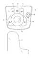
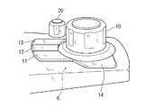
前記スイッチパネル部6の詳細が、図2、図3に示される。スイッチパネル部6には、以下に説明するような複数のスイッチが設けられている。まず、上下方向軸線回りに回転操作され、かつ押し下げ操作も可能なダイアルスイッチ10を有する。このダイアルスイッチ10の直前方に位置させて、車幅方向に沿って3つの押し下げスイッチ11、12、13が配設されている。また、ダイアルスイッチ10の左側方直近には、押し下げスイッチ14が配設され、右側方直近には押し下げスイッチ15が配設されている。 Details of the
スイッチパネル部6には、さらに、音量調整スイッチ20が配設されている。この音量調整スイッチ20は、前記押し下げスイッチ11〜13の配列方向右方側に配設されている。つまり、音量調整スイッチ20は、ダイアルスイッチ10を挟んで、ステアリングハンドル3やパーキングブレーキレバー8とは反対側に配設されている。 The
音量調整スイッチ20の前後方向位置は、前記3つの押し下げスイッチ11〜13の前後方向長さ範囲と重なるように、つまり押し下げスイッチ11〜13を車幅方向に延長した範囲に位置設定されている。また、音量調整スイッチ20の一部がダイアルスイッチ10の前端部と前後方向位置が重なるようにされている(ダイアルスイッチ10の車幅方向延長範囲内に、音量調整スイッチ20の後部が位置される)。 The position of the
ダイアルスイッチ10は、回転操作される関係上、例えば突出高さが例えば2〜3cm程度とされた略円柱状に形成されている。また、ダイアルスイッチ10は、手のひらが載置された状態であるいは親指、人差し指、中指の3本の手指先で回転操作しやすいように、大径とされている(大人の指2〜4本分の直径で、例えば4〜6cm程度)。 The
一方、音量調整スイッチ20も回転操作に応じて音量調整されるようになっており、例えば突出高さが2〜3cm程度の略円柱状とされている。また、音量調整スイッチ20は、手指(特に親指と人差し指)で回転操作しやすいように、ダイアルスイッチ10よりも十分に小径とされている(例えば大人の指1本分程度の直径で、例えば1〜2cm程度)とされている。音量調整スイッチ20は、ダイアルスイッチ10の近傍ではあるが、ダイアルスイッチ10との間に指(大人の1本の指)が挟まれない程度の小間隔(例えば2〜3cm程度)を有するように位置設定されている。 On the other hand, the
押し下げスイッチ11〜15は、ダイアルスイッチ10や音量調整スイッチ20に比して、その高さは十分低くされている(例えば突出高さが2〜5mm程度)。また、各押し下げスイッチ11〜15は、1本の指先で押し下げ操作しやすいように、比較的大きな面積を有している(例えば、車幅方向幅が1.5〜2.0cm程度で、前後方向長さが例えば2〜3cm程度)。ただし、ダイアルスイッチ10の直前方に配設された3つの押し下げスイッチ11〜13のうち、中央の押し下げスイッチ12は、後述するように、使用頻度が高いホームスイッチとされている関係上、その幅および突出高さが、押し下げスイッチ11及び13に比して大きくされている。なお、中央の押し下げスイッチ12の区別のために、例えばその上面に凹部あるいは突部を形成する等により、押し下げスイッチ11、13と明確に識別できるようにすることもできる。 The push-down
ダイアルスイッチ10とアームレスト7の前端とは、比較的近い位置とされている。具体的には、図4に示すように、運転者の腕30(実施形態では右手)をアームレスト7に載置した状態で、肘を固定して手首を下方へ曲げた際に、手のひらがダイアルスイッチ10の直上方に位置されて、指の付け根付近がダイアルスイッチ10の前端部に位置するようにされている。 The
図4に示すように、手のひらをダイアルスイッチ10上に触れた状態で、指先を若干下方へ曲げることにより、人差し指30aでもって押し下げスイッチ11を楽に押し下げ操作可能となっている。同様にして、中指30bでもって、押し下げスイッチ12を楽に押し下げ操作可能となっている。薬指30cでもって、押し下げスイッチ13を楽に押し下げ操作可能となっている。親指30dでもって、押し下げスイッチ14を楽に押し下げ操作可能となっている。小指30eでもって、押し下げスイッチ15を楽に押し下げ操作可能となっている。このように、押し下げスイッチとして、手指の位置と数に対応させて11〜15の5つ設けることにより、運転者に対して各押し下げスイッチ11〜15のスイッチ操作を習熟(記憶)させる効果が大きいものとなる。 As shown in FIG. 4, the push-
各スイッチ10〜16、20の上面は、それぞれアームレスト7の上面よりも低くされている(例えば、アームレスト7の先端部上面に対して、ダイアルスイッチ10の上面が3〜10cm程度低くされている)。これにより、アームレスト7に腕30を載置した状態で、手首から先が自然に垂れる状態で、各種スイッチ10〜16が操作できるようにされている。この状態から、手首付近を中心にして手先を図4時計方向へ若干移動させることにより、音量調整スイッチ20を操作できるようになっている。 The upper surfaces of the
再び図1において、インストルメントパネル1上には、車幅方向中央部において、例えば液晶画面等を利用して構成された薄型のディスプレイ(表示画面)40が配設されている。また、インストルメントパネル1上には、ステアリングハンドル3のまっすぐ前方位置において、ヘッドアップディスプレイ41が配設されている。各ディスプレイ40、41は、運転者から目視し易い位置とされている。 Referring again to FIG. 1, a thin display (display screen) 40 configured using, for example, a liquid crystal screen is disposed on the instrument panel 1 at the center in the vehicle width direction. A head-up
前記各スイッチ10〜16は、実施形態では、前記ディスプレイ40に表示される画面の操作用とされている。この各スイッチ10〜16の操作に関連した画面操作のための制御系統例について、図5を参照しつつ説明する。まず、Uは、マイクロコンピュータを利用して構成されたコントローラ(制御ユニット)である。このコントローラUは、例えばナビゲーション装置51、各種オーディオ機器52、テレビチューナ53の作動状態に応じた表示内容をディスプレイ40に表示させるように制御する。また、上記機器類51〜53について共通とされたスピーカ54の音量を制御する。 In the embodiment, each of the
各スイッチ10〜16の機能について説明する。まず、ダイアルスイッチ10は、その回転操作によって、ディスプレイ40に表示される複数の表示モードの中から1つの表示モードを選択する。そして、中央スイッチ16を操作することにより、ダイアルスイッチ10で選択されている表示モードに応じた画面が、ディスプレイ40に表示される。 The function of each switch 10-16 is demonstrated. First, the
押し下げスイッチ11は、オーディオ機器52選択用の画面を表示させるためのショートカットキーとされている(オーディオ選択キー)。押し下げスイッチ12は、選択対象となる全ての機能をその選択のために表示させるためのショートカットキーとされている(ホームキー)。押し下げスイッチ13は、ナビゲーション装置52を選択するためのショートカットキーとされている(ナビキー)。押し下げスイッチ14は、ディスプレイ40の表示内容を、1つ前の表示内容に切換えるためのショートカットキーとされている(戻るキー)。押し下げスイッチ15は、あらかじめ運転者により登録された画面を表示させるショートカットキーとされている(お気に入りキー)。 The
次に、各種スイッチ1−〜16、20の操作に応じた制御ユニットUによるディスプレイ40の画面制御例について説明する。まず、ホームキーとなる押し下げスイッチ12が押し下げ操作されると、図6に示すようなホーム画面がディスプレイ40に表示される。このホーム画面では、全ての機能を選択できるようになっており、表示されていない機能は、ダイアルスイッチ10を回転操作することにより表示されるようになる。ディスプレイ40には、左右に矢印が付された補助表示50が表示されて、ダイアルスイッチ10の回転操作によって、所望の機能(表示モード)が選択できることを報知するようになっている。 Next, an example of screen control of the
図6では、戻る表示61、オーディオ表示62、ナビゲーション表示63、お気に入り表示64、テレビ表示65、設定表示66の6種類が表示されている。この状態で、現在選択されている機能を示す1つの表示(表示モード)が、上記各表示61〜66のうちいずれか1つが例えば点滅されることに報知され、図6では、ナビゲーション表示63が点滅されて選択状態にあることが示される。なお、選択されていることを示すカーソル機能としては、点滅に限らず、例えば、別途各表示61〜66のいずれか1つにのみ棒状のカーソルを点灯表示させる等、適宜の手法を採択できる。 In FIG. 6, six types of
ナビゲーション表示63が点滅されて選択状態にあることが示される図6の状態で、ダイアルスイッチ10を押し下げ操作すると、ディスプレイ40の表示内容が、図7に示すように、ナビゲーション装置51用の表示内容となる車両の現在位置を中心とした地図表示に切換えられる。ディスプレイ40にある表示内容が表示されている状態(例えばテレビ放映されている状態)で、ショートカットキーとしての押し下げスイッチ13を操作したときは、ディスプレイ40の表示内容が、図7のような車両の現在地位を中心とした地図表示に一気に切換えられる。 When the
図6の状態から、ダイアルスイッチ10を回転操作してオーディオ表示62を選択した後、押し下げ操作することにより、図8に示すようなオーディオ機器の選択用画面に切換えられる。ショートカットキーとしての押し下げスイッチ11を操作したときは、ディスプレイ40の表示内容が、一気に図8のような表示内容に切換えられる。 From the state shown in FIG. 6, the
図8の状態では、USB表示71(USBメモリに記憶された音楽の選択用)、DVD表示72(映画の選択用)、MD表示73(ミニディスクに記憶された音楽の再生選択用)、テープ表示74(カセットテープに記憶された音楽の再生選択用)、AM表示(AMラジオ放送の選択用)、FM表示76(FMラジオ放送の選択用)とされている。 In the state of FIG. 8, a USB display 71 (for selecting music stored in the USB memory), a DVD display 72 (for selecting movies), an MD display 73 (for selecting playback of music stored on a mini-disc), tape A display 74 (for selecting reproduction of music stored on the cassette tape), an AM display (for selecting AM radio broadcast), and an FM display 76 (for selecting FM radio broadcast) are displayed.
図8の状態では、FM表示76が点滅されていて、FMラジオ放送が選択された状態である。この選択状態でダイアルスイッチ10を押し下げ操作することにより、次の階層となる複数のFM放送曲が、選択のために図6、図8と同じような態様でもって表示される。表示された複数のFM放送局をダイアルスイッチ10の回転操作選択し、この後ダイアルスイッチ10を押し下げ操作することにより、所望のFM放送局が決定されて、その放送がスピーカ54から出力されることになる。なお、お気に入りの登録は、例えば図6の設定表示66を選択、決定した後、その下にある階層から選択、決定される。勿論、階層数は、適宜設定できる。また、図6のナビゲーション表示63を選択、決定したときに、即座に現在位置を中心とした地図情報を表示させるのではなく、ナビゲーション装置54に関連した各種機能を複数表示させ、この複数表示の1つとして現在位置の地図表示を選択するための表示を行わせる等、階層の設定等は適宜変更できる。 In the state of FIG. 8, the
上述のようにして、所望の機能(表示モード)が選択、決定されて、決定された内容に応じた表示内容がディスプレイ40に表示される。また、スピーカ54から音楽や音声が適宜出力されることになる。 As described above, a desired function (display mode) is selected and determined, and display content corresponding to the determined content is displayed on the
ここで、各スイッチ10〜15によってディスプレイ40の表示内容が切換えられるとき、この切換に応じてスピーカ54からの音量が大きく変化する場合がある。例えば、テレビ放映からAMラジオ放送に切換えたとき、音量が大きく変化される場合がある。この場合は、図4に示すような状態、つまり腕30をアームレスト7に載置した状態で、手首から先の部分を若干図4時計方向に回動(移動)させることにより、音量調整スイッチ20にアクセスすることができ、音量調整を簡単に行うことができる。運転者は、ディスプレイ40の表示内容切換えのための操作や音量調整を、前方を注視したまま簡単かつ確実に行うことができる。 Here, when the display contents of the
以上実施形態について説明したが、本発明は、実施形態に限定されるものではなく、特許請求の範囲の記載された範囲において適宜の変更が可能である。ダイアルスイッチ10や押し下げスイッチ11〜15の機能は、ディスプレイ40での画面操作に関連したものであれば、適宜設定できるものであり、またヘッドアップディスプレイ41での画面操作用として用いることもできる。ダイアルスイッチ10は、前後・左右にチルト操作可能として、この操作をもディスプレイ40(41)の画面操作用としての機能を割り当てるようにすることもできる(例えば前後チルトで次画面への切換と前画面への切換えを行い、左右チルトで画面のスクロールを行う等)。音量調整スイッチ20を、ダイアルスイッチ10よりもステアリングハンドル3に近い側に配設したり、パーキングブレーキレバー8に近い側に配置するようにしてもよい。音量調整スイッチ20は、回転式に限らず、シーソー式あるいはスライド式等、適宜の形式のものを選択でき、また音量調整スイッチ20をセンターコンソール4上に設けないものであってもよい。ダイアルスイッチ10、押し下げスイッチ11〜15の操作に応じた画面表示の制御対象となる機器としては、例えば空調機器等適宜選択できる。勿論、本発明の目的は、明記されたものに限らず、実質的に好ましいあるいは利点として表現されたものを提供することをも暗黙的に含むものである。Although the embodiments have been described above, the present invention is not limited to the embodiments, and appropriate modifications can be made within the scope of the claims. The functions of the
本発明は、車載ディスプレイの表示内容切換用として好適である。 The present invention is suitable for switching the display contents of an in-vehicle display.
U:コントローラ
1:インストルメントパネル
3:ステアリングハンドル
4:センターコンソール
6:スイッチパネル部
7:アームレスト
10:ダイアルスイッチ
11〜15:押し下げスイッチ
20:音量調整スイッチ
40、41:ディスプレイ
51:ナビゲーション装置
52:オーディオ機器
53:TVチューナ
54:スピーカU: Controller 1: Instrument panel 3: Steering handle 4: Center console 6: Switch panel section 7: Armrest 10: Dial switches 11-15: Push-down switch 20:
Claims (6)
Translated fromJapaneseセンターコンソール上に設けられたアームレストと、
前記アームレストの前方において前記センターコンソール上に設けられ、該アームレストに腕を載置した状態で操作可能なダイアルスイッチと、
前記ダイアルスイッチを含む該ダイアルスイッチよりも前方の範囲において、該ダイアルスイッチを取り巻くようにして前記センターコンソール上に設けられ、前記アームレストに腕を載置した状態で手指によって押し下げ操作可能な5つの押し下げスイッチと、
を備え、
前記ダイアルスイッチおよび前記押し下げスイッチはそれぞれ、前記ディスプレイにおける画面操作用とされ、
前記5つの押し下げスイッチのうち、使用頻度の高い3つの押し下げスイッチが前記ダイアルスイッチの前側に配設される一方、使用頻度の低い2つの押し下げスイッチが該ダイアルスイッチの左右側方に配設され、
前記各押し下げスイッチは、あらかじめ対応付けられている特定の1つの画面表示を前記ディスプレイに表示させるためのショートカットキーとされている、
ことを特徴とする車両用入力装置。A display provided at a position visible from the driver;
An armrest provided on the center console;
A dial switch provided on the center console in front of the armrest and operable in a state where an arm is placed on the armrest;
Five push-downs that are provided on the center console so as to surround the dial switch and that can be pushed down with fingers while the arm is placed on the armrest in a range in front of the dial switch including the dial switch. A switch,
With
The dial switch and the push-down switch are each for screen operation on the display,
Among the five push-down switches, three push switches that are frequently used are disposed on the front side of the dial switch, while two push switches that are less frequently used are disposed on the left and right sides of the dial switch.
Each of the push-down switches is a shortcut key for causing the display to display a specific screen image associated in advance.
An input device for a vehicle.
前記ダイアルスイッチの前側に配設された3つの押し下げスイッチのうち、真ん中に位置される押し下げスイッチが、各種機能を選択するための画面表示を前記ディスプレイに表示させるためのホームキーとされている、ことを特徴とする車両用入力装置。In claim1 ,
Of the three push switches disposed on the front side of the dial switch, the push switch located in the middle is a home key for causing the display to display a screen display for selecting various functions. An input device for a vehicle.
前記ダイアルスイッチの前側に配設された前記3つの押し下げスイッチにおいて、真ん中に位置される押し下げスイッチの幅および突出高さがそれぞれ、左右隣にある押し下げスイッチに比して大きくされている、ことを特徴とする車両用入力装置。In claim2 ,
In the three push-down switches arranged on the front side of the dial switch, the width and the protruding height of the push-down switch positioned in the middle are respectively larger than the push-down switch adjacent to the left and right. A vehicle input device.
前記5つの押し下げスイッチのうちもっとも使用頻度の低い押し下げスイッチが、該ダイアルスイッチを挟んでステアリングハンドルとは反対側に位置されて、前記アームレストに腕を載置した状態で小指によって押し下げ操作される、ことを特徴とする車両用入力装置。In any one of Claims 1 thru | or3 ,
Of the five push-down switches, the push-down switch that is least frequently used is positioned on the opposite side of the steering handle across the dial switch, and is pushed down with a little finger in a state where an arm is placed on the armrest. An input device for a vehicle.
前記5つの押し下げスイッチのうち3つの押し下げスイッチが、前記アームレストに腕を載置した状態で人差し指、中指、薬指で個別に操作されるように、前記ダイアルスイッチの前側において車幅方向に沿って3個設けられ、
前記5つの押し下げスイッチのうち2つの押し下げスイッチが前記ダイアルスイッチの左右側方に位置されて、前記アームレストに腕を載置した状態で、その一方の押し下げスイッチが親指で操作され、他方の押し下げスイッチが小指で操作される、
ことを特徴とする車両用入力装置。In any one of Claims 1 thru | or4 ,
Of the five push-down switches, three push-down switches are arranged along the vehicle width direction on the front side of the dial switch so as to be individually operated with the index finger, middle finger, and ring finger with the arm placed on the armrest. Provided,
Of the five push-down switches, two push-down switches are positioned on the left and right sides of the dial switch, and with one arm placed on the armrest, one push-down switch is operated with the thumb and the other push-down switch Is operated with the little finger,
An input device for a vehicle.
前記ダイアルスイッチの上面が、前記アームレストの上面よりも低い位置となるようにされ、
前記押し下げスイッチの上面が、前記ダイアルスイッチの上面よりもさらに低い位置とされている、
ことを特徴とする車両用入力装置。
In any one of Claims 1 thru | or5 ,
The upper surface of the dial switch is positioned lower than the upper surface of the armrest;
The upper surface of the push-down switch is at a lower position than the upper surface of the dial switch,
Vehicle input device according to claim andthis.
Priority Applications (1)
| Application Number | Priority Date | Filing Date | Title |
|---|---|---|---|
| JP2012262971AJP5998885B2 (en) | 2012-11-30 | 2012-11-30 | Vehicle input device |
Applications Claiming Priority (1)
| Application Number | Priority Date | Filing Date | Title |
|---|---|---|---|
| JP2012262971AJP5998885B2 (en) | 2012-11-30 | 2012-11-30 | Vehicle input device |
Publications (2)
| Publication Number | Publication Date |
|---|---|
| JP2014108671A JP2014108671A (en) | 2014-06-12 |
| JP5998885B2true JP5998885B2 (en) | 2016-09-28 |
Family
ID=51029567
Family Applications (1)
| Application Number | Title | Priority Date | Filing Date |
|---|---|---|---|
| JP2012262971AActiveJP5998885B2 (en) | 2012-11-30 | 2012-11-30 | Vehicle input device |
Country Status (1)
| Country | Link |
|---|---|
| JP (1) | JP5998885B2 (en) |
Families Citing this family (1)
| Publication number | Priority date | Publication date | Assignee | Title |
|---|---|---|---|---|
| SE544078C2 (en)* | 2018-06-15 | 2021-12-14 | Ghsp Inc | Rotary shifter with secondary rotary knob |
Family Cites Families (2)
| Publication number | Priority date | Publication date | Assignee | Title |
|---|---|---|---|---|
| WO2002040307A1 (en)* | 2000-11-14 | 2002-05-23 | Volkswagen Aktiengesellschaft | Multifunction operating device |
| JP2003327059A (en)* | 2002-03-08 | 2003-11-19 | Calsonic Kansei Corp | Input device for vehicle |
- 2012
- 2012-11-30JPJP2012262971Apatent/JP5998885B2/enactiveActive
Also Published As
| Publication number | Publication date |
|---|---|
| JP2014108671A (en) | 2014-06-12 |
Similar Documents
| Publication | Publication Date | Title |
|---|---|---|
| US6903652B2 (en) | Input apparatus for vehicle-installed instruments | |
| JP7171472B2 (en) | Steering switch device and steering switch system | |
| JP6136627B2 (en) | Vehicle information display device | |
| US7603214B2 (en) | In-vehicle input unit | |
| US10166868B2 (en) | Vehicle-mounted equipment operation support system | |
| US20190322176A1 (en) | Input device for vehicle and input method | |
| JP5079582B2 (en) | Touch sensor | |
| JP2011113345A (en) | In-vehicle display system | |
| KR20210156126A (en) | Display control system using knob | |
| JP2001350561A (en) | Function controller equipped with at least one selector | |
| JP6119456B2 (en) | Vehicle information display device | |
| JP3668834B2 (en) | Vehicle display device | |
| JP6221952B2 (en) | Input device | |
| JP5954156B2 (en) | In-vehicle information processing equipment | |
| JP2013161230A (en) | Input device | |
| JP6201864B2 (en) | Vehicle control device | |
| JP5998885B2 (en) | Vehicle input device | |
| JP5935671B2 (en) | Vehicle input device | |
| JP4623980B2 (en) | Vehicle control device | |
| JP2015162361A (en) | Equipment operation device | |
| KR102867703B1 (en) | Display control system using knob | |
| US20180086289A1 (en) | Vehicle-mounted equipment operating device | |
| KR20220005947A (en) | Display control system using knob | |
| KR20220005946A (en) | Display control system using knob | |
| KR20230009161A (en) | Display control system using knob |
Legal Events
| Date | Code | Title | Description |
|---|---|---|---|
| A621 | Written request for application examination | Free format text:JAPANESE INTERMEDIATE CODE: A621 Effective date:20150312 | |
| A131 | Notification of reasons for refusal | Free format text:JAPANESE INTERMEDIATE CODE: A131 Effective date:20151222 | |
| A977 | Report on retrieval | Free format text:JAPANESE INTERMEDIATE CODE: A971007 Effective date:20151225 | |
| A521 | Written amendment | Free format text:JAPANESE INTERMEDIATE CODE: A523 Effective date:20160216 | |
| TRDD | Decision of grant or rejection written | ||
| A01 | Written decision to grant a patent or to grant a registration (utility model) | Free format text:JAPANESE INTERMEDIATE CODE: A01 Effective date:20160802 | |
| A61 | First payment of annual fees (during grant procedure) | Free format text:JAPANESE INTERMEDIATE CODE: A61 Effective date:20160815 | |
| R150 | Certificate of patent (=grant) or registration of utility model | Ref document number:5998885 Country of ref document:JP Free format text:JAPANESE INTERMEDIATE CODE: R150 |