JP5997078B2 - Screwdriver for attaching medical screws - Google Patents
Screwdriver for attaching medical screwsDownload PDFInfo
- Publication number
- JP5997078B2 JP5997078B2JP2013046898AJP2013046898AJP5997078B2JP 5997078 B2JP5997078 B2JP 5997078B2JP 2013046898 AJP2013046898 AJP 2013046898AJP 2013046898 AJP2013046898 AJP 2013046898AJP 5997078 B2JP5997078 B2JP 5997078B2
- Authority
- JP
- Japan
- Prior art keywords
- shaft
- cylindrical body
- cylinder
- moving member
- grip
- Prior art date
- Legal status (The legal status is an assumption and is not a legal conclusion. Google has not performed a legal analysis and makes no representation as to the accuracy of the status listed.)
- Active
Links
- 210000001519tissueAnatomy0.000description18
- 238000003780insertionMethods0.000description5
- 230000037431insertionEffects0.000description5
- 238000005553drillingMethods0.000description4
- 210000001264anterior cruciate ligamentAnatomy0.000description2
- 210000000988bone and boneAnatomy0.000description2
- 230000007423decreaseEffects0.000description2
- 210000000689upper legAnatomy0.000description2
- 238000013459approachMethods0.000description1
- 230000000975bioactive effectEffects0.000description1
- 239000003462bioceramicSubstances0.000description1
- 230000006835compressionEffects0.000description1
- 238000007906compressionMethods0.000description1
- 230000000694effectsEffects0.000description1
- 210000000629knee jointAnatomy0.000description1
- 210000003041ligamentAnatomy0.000description1
- 239000000463materialSubstances0.000description1
- 238000000034methodMethods0.000description1
- 230000000149penetrating effectEffects0.000description1
- 229920000747poly(lactic acid)Polymers0.000description1
- 239000004626polylactic acidSubstances0.000description1
- 229920000642polymerPolymers0.000description1
- 239000000843powderSubstances0.000description1
- 238000004080punchingMethods0.000description1
- 238000006748scratchingMethods0.000description1
- 230000002393scratching effectEffects0.000description1
- 210000002435tendonAnatomy0.000description1
Images


Landscapes
- Surgical Instruments (AREA)
Description
Translated fromJapanese本発明は医療用ネジを取り付けるためのドライバーに関し、更に詳しくは、医療用ネジを生体の硬組織の所定箇所にねじ込んで取り付けた後に、ドライバーのシャフト先端の係合軸部を医療用ネジの被係合孔から容易に抜き取ることができるように改良した、操作性の良いドライバーに関する。 The present invention relates to a driver for attaching a medical screw, and more specifically, after the medical screw is screwed and attached to a predetermined portion of a hard tissue of a living body, the engagement shaft portion of the shaft end of the driver is attached to the medical screw. The present invention relates to a driver with improved operability, which is improved so that it can be easily removed from an engagement hole.
医療用ネジを取付けるドライバーとして、例えば、膝関節の前十字靱帯を置換、固定するための生物分解性の締まり嵌めネジを骨内にねじ込むドライバーが知られている(特許文献1)。このドライバーは、先端の六角形の係合軸部を締まり嵌めネジの六角形の被係合孔に挿入して係合させ、締まり嵌めネジを大腿骨等に形成した孔にねじ込んで置換用の前十字靱帯を固定した後、ドライバー先端の係合軸部を締まり嵌めネジの被係合孔から抜き取って使用するものである。 As a driver for attaching a medical screw, for example, a driver is known in which a biodegradable interference screw for replacing and fixing an anterior cruciate ligament of a knee joint is screwed into a bone (Patent Document 1). In this screwdriver, the hexagonal engagement shaft at the tip is inserted into and engaged with the hexagonal engaged hole of the interference fitting screw, and the interference fitting screw is screwed into the hole formed in the femur or the like for replacement. After fixing the anterior cruciate ligament, the engaging shaft portion at the tip of the driver is extracted from the engaged hole of the interference fitting screw and used.
また、握り部と、該握り部の一端部に突設されたシャフト部と、該シャフト部の基端部に形成された雄ネジと、該シャフト部の外側に移動可能に嵌入されるとともに上記雄ネジに螺合する雌ネジを備えた筒体と、該筒体に設けられた回転ハンドルとを備え、上記シャフト部の先端が医療用スクリューのドライブ孔に嵌入するビット先に形成されてなる医療用ドライバーも提案されている(特許文献2)。 In addition, the grip portion, a shaft portion protruding from one end portion of the grip portion, a male screw formed at the base end portion of the shaft portion, and a movably fitted outside the shaft portion and the above A cylindrical body provided with a female screw threadedly engaged with a male screw, and a rotary handle provided on the cylindrical body, the tip of the shaft portion being formed at a bit tip that fits into a drive hole of a medical screw A medical driver has also been proposed (Patent Document 2).
しかしながら、前記特許文献1のドライバーでは、大腿骨等に形成した孔に締まり嵌めネジをねじ込んだ後、ドライバーの先端係合部を締まり嵌めねじの被係合孔から抜き取る際に、ドライバーの先端係合部が締まり嵌めネジの被係合孔に強く食い込んでいるために抜き取り難くなるという問題があった。 However, in the driver of
これに対し、前記特許文献2の医療用ドライバーは、ねじ込んだ医療用スクリューのドライブ孔からシャフト部のビット先を抜き取るときに、筒体の回転ハンドルを回転して、シャフト部の雄ネジと筒体の雌ネジとで筒体を前進させながら筒体の先端でスクリューの頭部を押していき、相対的にビット先を後退させることによって、シャフト部のビット先をスクリューのドライブ孔から簡単に外すことができるため、上記のような問題は生じない。
けれども、筒体の先端がスクリューの頭部に接触しながら回転するため、スクリューの頭部に傷が生じたり、削り屑が発生して周囲の生体組織に付着する恐れがあった。On the other hand, the medical driver of
However, since the tip of the cylinder rotates while contacting the head of the screw, there is a risk that the head of the screw may be damaged or shavings may be generated and adhere to the surrounding living tissue.
本発明は上記事情の下になされたもので、その解決しようとする課題は、シャフトを無理に引き抜いたり、シャフトに外挿された筒体を回転させたりしないで、シャフト先端の係合軸部を医療用ネジの被係合孔から容易に抜き取ることができる、操作性の良いドライバーを提供することにある。 The present invention has been made under the circumstances described above, and the problem to be solved is an engagement shaft portion at the tip of the shaft without forcibly pulling out the shaft or rotating the cylinder body extrapolated to the shaft. It is an object of the present invention to provide a driver with good operability that can be easily removed from the engaged hole of a medical screw.
上記課題を解決するため、本発明に係る医療用ネジを取り付けるためのドライバーは、
グリップから突き出したシャフトの先端に、医療用ネジの被係合孔に挿入して係合させる係合軸部が形成されたドライバー本体と、
ドライバー本体のシャフトにその長さ方向に移動自在に外挿され、先端が医療用ネジの後端に当接又は近接する筒体と、
ドライバー本体のグリップと筒体の間に設けられ、筒体を回転させないでシャフトの先端方向に移動させる筒体移動部材と、
を備えたことを特徴とするものである。In order to solve the above problems, a screwdriver for attaching a medical screw according to the present invention is:
A driver main body formed with an engagement shaft portion to be inserted into and engaged with the engaged hole of the medical screw at the tip of the shaft protruding from the grip;
A cylindrical body that is slidably inserted in the length direction of the shaft of the driver body, and whose tip abuts on or close to the rear end of the medical screw;
A cylinder moving member that is provided between the grip of the driver body and the cylinder, and moves in the tip direction of the shaft without rotating the cylinder;
It is characterized by comprising.
本発明のドライバーにあっては、筒体移動部材がグリップと筒体の双方に当接し、筒体移動部材の力点に加えた力を、筒体移動部材とグリップとの当接部を支点として、筒体移動部材と筒体との当接部において、筒体をシャフトの先端方向に移動させる力に変換して筒体に作用させるものであることが好ましい。
また、筒体移動部材は、グリップの先端部と、筒体の後端部において筒体と交差する方向に突き出した突出部の双方に当接するものであることが好ましい。In the driver of the present invention, the cylinder moving member abuts both the grip and the cylinder, and the force applied to the force point of the cylinder moving member is used as a fulcrum at the contact portion between the cylinder moving member and the grip. In the contact portion between the cylindrical body moving member and the cylindrical body, it is preferable that the cylindrical body is converted into a force that moves the cylindrical body in the distal end direction of the shaft and is applied to the cylindrical body.
Moreover, it is preferable that the cylindrical body moving member is in contact with both the front end portion of the grip and the protruding portion protruding in the direction intersecting the cylindrical body at the rear end portion of the cylindrical body.
本発明のドライバーでは、ドライバー本体のシャフト先端の係合軸部を医療用ネジの被係合孔に挿入、係合させ、医療用ネジを生体の硬組織の所定箇所にねじ込んで取り付けた後、筒体移動部材で筒体を回転させないでシャフトの先端方向に移動させることにより、筒体の先端で医療用ネジの後端を押しながらシャフト先端の係合軸部を医療用ネジの被係合孔から容易に抜き取ることができる。また、筒体を回転させないので、筒体の先端によって医療用ネジの後端に傷が生じたり、削り屑が発生して周囲の生体組織に付着したりする恐れも解消される。 In the driver of the present invention, after inserting and engaging the engaging shaft portion of the shaft tip of the driver body into the engaged hole of the medical screw, and screwing the medical screw into a predetermined location of the hard tissue of the living body, By moving the cylinder body toward the tip of the shaft without rotating the cylinder with the cylinder moving member, the medical screw is engaged with the engagement shaft at the tip of the shaft while pushing the rear end of the medical screw at the tip of the cylinder. It can be easily extracted from the hole. Further, since the cylindrical body is not rotated, the possibility of scratching the rear end of the medical screw due to the distal end of the cylindrical body or generation of shavings and adhering to the surrounding biological tissue is also eliminated.
特に、筒体移動部材がグリップと筒体の双方に当接し、筒体移動部材の力点に加えた力を、筒体移動部材とグリップとの当接部を支点として、筒体移動部材と筒体との当接部において、筒体をシャフトの先端方向に移動させる力に変換して筒体に作用させるものであると、力の変換が容易に行われ、変換した力によって筒体がシャフトの先端方向にスムーズに移動して医療用ネジの後端を押すため、医療用ネジの被係合孔からシャフト先端の係合軸部を抜き取る操作が一層し易くなり、操作性が大幅に向上する。 In particular, the cylinder moving member and the cylinder are in contact with both the grip and the cylinder, and the force applied to the force point of the cylinder moving member is used as a fulcrum at the contact portion between the cylinder moving member and the grip. When the cylindrical body is converted into a force that moves the cylindrical body in the distal direction of the shaft and acts on the cylindrical body at the contact portion with the body, the force is easily converted, and the cylindrical body is shafted by the converted force. Since it moves smoothly in the direction of the tip of the screw and pushes the rear end of the medical screw, it is easier to remove the engaging shaft at the tip of the shaft from the engaged hole of the medical screw, greatly improving operability. To do.
そして、筒体移動部材が、グリップの先端部と、筒体の後端部において筒体と交差する方向に突き出した突出部の双方に当接するものであると、筒体移動部材と突出部との当接部で変換した力を突出部を介して筒体に確実に作用させることができるので、医療用ネジの被係合孔からシャフト先端の係合軸部を確実に引き抜くことができる。 And when the cylindrical body moving member comes into contact with both the front end portion of the grip and the protruding portion protruding in the direction intersecting the cylindrical body at the rear end portion of the cylindrical body, the cylindrical body moving member and the protruding portion Since the force converted by the contact portion can be reliably applied to the cylindrical body via the protruding portion, the engagement shaft portion at the distal end of the shaft can be reliably pulled out from the engaged hole of the medical screw.
以下、図面を参照して、本発明に係るドライバーの実施形態を説明する。 Hereinafter, embodiments of a driver according to the present invention will be described with reference to the drawings.
図1は本発明の一実施形態に係るドライバーの側面図、図2は同ドライバーの分解側面図、図3は同ドライバーの筒体移動部材を操作して筒体をシャフトの先端方向に移動させたところを示す側面図、図4の(a)は同ドライバーのグリップの断面図、図4の(b)はシャフトを先端側に少し移動させた状態のグリップの断面図、図5は同ドライバーの筒体の正面図、図6は同ドライバーの筒体移動部材の正面図である。 FIG. 1 is a side view of a driver according to an embodiment of the present invention, FIG. 2 is an exploded side view of the driver, and FIG. 3 is an operation of the cylinder moving member of the driver to move the cylinder toward the distal end of the shaft. 4A is a sectional view of the grip of the driver, FIG. 4B is a sectional view of the grip with the shaft slightly moved to the tip side, and FIG. 5 is the driver. FIG. 6 is a front view of the cylinder moving member of the driver.
図1〜図3に示す実施形態のドライバーは、ドライバー本体1と、筒体2と、筒体移動部材3とを備えたもので、ドライバー本体1のシャフト12の先端を医療用ネジ4に挿入して係合させ、生体の硬組織の所定箇所に医療用ネジ4をねじ込んで取り付けるものである。 The driver of the embodiment shown in FIGS. 1 to 3 includes a driver
ドライバー本体1は、手に握って回転させるグリップ11と、このグリップ11から突き出したシャフト12を有するものであって、このシャフト12の先端には、医療用ネジ4の六角形の被係合孔4aに挿入して係合させる小径の六角形の係合軸部12aが形成されている。医療用ネジ4の被係合孔4aは、その後端の開口から先端に近づくにつれて孔径が少しずつ小さくなる先窄まりのテーパー状に形成されているので、これに対応して係合軸部12aも先端に近づくにつれて軸径が少しずつ小さくなる先窄まりのテーパー状に形成されている。この実施形態で使用する医療用ネジ4は、生体活性なバイオセラミックス粉体を含んだポリ乳酸などの生体内分解吸収性ポリマーからなる、ネジ頭部がない医療用ネジであって、靱帯や腱を骨関節などに移植、固定するためのものであるが、これ以外の種々の材質および種々の形状の公知の医療用ネジも使用できることは言うまでもない。なお、シャフト先端の係合軸部12aと医療用ネジ4の被係合孔4aの形状は、互いに係合、被係合の関係を有する形状であって、係合軸部12aを被係合孔4aに挿入、係合させてシャフト12を回転させたとき、係合軸部12aの回転トルクを被係合孔4aに確実に伝達して医療用ネジ4を回転させることができる形状であれば、上記の六角形に限らず任意の形状となし得るものである。 The driver
上記グリップ11は、図4に示すように、グリップ本体11aと、シャフトロック部材11bと、異径筒状軸11cと、ワイヤ止めネジ11dなどを備えたもので、異径筒状軸11cの後半の小径軸部はグリップ本体11aの中心孔に嵌挿され、先端が尖った3本の止めネジ11eによって、回転しないように且つ抜けないように固定されている。 As shown in FIG. 4, the
異径筒状軸11cの先端側の大径軸部の内部には、三角孔形状(角部を面取りした三角孔形状)の被係合孔が形成されており、この被係合孔に対応する三角棒状(角部を面取りした三角棒状)に形成されたシャフト12後端の係合軸部12bがこの被係合孔に挿入されて回転不能に係合している。そして、このシャフト12は、シャフトロック部材11bによって異径筒状軸11cから抜け出さないようにロックされている。 A to-be-engaged hole having a triangular hole shape (triangular hole shape with chamfered corners) is formed inside the large-diameter shaft portion on the distal end side of the different-diameter
このシャフトロック部材11bは、異径筒状軸11cの先端側の大径軸部の筒壁部に形成された複数の穴にそれぞれ嵌め込まれた複数の球体11gと、シャフトロック部材11bを後方に向かって付勢する圧縮スプリング11hと、シャフトロック部材11bの内部に形成された先窄まり状のテーパー面11iなどを備えたもので、図4の(a)に示すように、テーパー面11iで押圧された球体11gが、シャフト12の後端部に形成された環状の溝部12cに嵌まり込むことによって、シャフト12をグリップ11の異径筒状軸11cから抜け出さないようにロックしている。そして、図4の(b)に示すように、スプリング11bの弾発力に抗してシャフトロック部材11bを先端側へ移動させると、テーパー面11iによる球体11gの押圧が解除されて、球体11gが遠心方向(シャフトから離れる方向)に移動可能な状態となるため、シャフト12を先端側へ引くと球体11gがシャフト12の溝部12cから浮き出してロックが解除され、シャフト12をグリップ11の異径筒状軸11cから簡単に引き抜くことができるようになっている。 The
このシャフト12は、中心線に沿って貫通するワイヤ挿通孔12d(図4を参照)を形成した中空のシャフトであって、その先端と後端には、前述したように医療用ネジ4の被係合孔4aに挿入して係合させる係合軸部12aと、異径筒状軸11cの被係合孔に挿入して係合させる係合軸部12bが形成されており、更に、シャフト先端の係合軸部12aの後方には目盛12e(図2を参照)が形成されている。この目盛12eは、シャフト先端の係合軸部12aを医療用ネジ4の被係合孔4aに挿入、係合させて、医療用ネジ4を生体の硬組織にねじ込むときに、医療用ネジ4の先端からの寸法、即ち、医療用ネジ4のねじ込み深さを示す目盛である。 This
グリップ本体11aには、その中心線に沿ってワイヤ挿通孔11fが形成されており、後述するように、医療用ネジ4を生体硬組織の所定のねじ込み位置まで案内するためのガイドワイヤ(不図示)が、このグリップ本体11aのワイヤ挿通孔11fから異径筒状軸11cの内孔及びシャフト12のワイヤ挿通孔12dを通って医療用ネジ4の先端開口まで挿通されるようになっている。そして、このガイドワイヤは、異径筒状軸11cの筒壁を貫通して内部にねじ込まれたワイヤ止めネジ11dによって固定されるようになっている。 A
上記シャフト12には、筒体2がシャフト12の長さ方向に移動自在(スライド自在)に外挿されており、この筒体2の後端はグリップ11の異径筒状軸11cの先端に当接している。そして、この筒体2の先端は、本実施形態では、図1に示すようにシャフト12先端の係合軸部12aを医療用ネジ4の被係合孔に挿入して係合させたときに、医療用ネジ4の後端に当接するようになっている。
なお、筒体2の先端は必ずしも医療用ネジ4の後端に当接する必要がなく、後述する筒体移動部材3によって筒体2が先方へ移動する距離よりも短い隙間を残して、医療用ネジ4の後端に近接するように構成してもよい。
また、前述したように、医療用ネジ4の被係合孔4aとシャフト先端の係合軸部12aは、いずれも先窄まりのテーパー状に形成されているので、医療用ネジ4の被係合孔4aの孔径の大きさを調整することにより、長さの異なる医療用ネジ4をシャフト先端の係合軸部12aに挿通、係合させる場合でも、同じ筒体2を使用することができる。The
It should be noted that the tip of the
Further, as described above, since the engaged
この筒体2の前半部分の側面には切り欠き窓部2aが形成されており、図1に示すように、この切り欠き窓部2aを通してシャフト12の目盛12eを読み取ることができるようになっている。また、この筒体2の後端近傍部位には、筒体2と交差する方向に突き出した鍔状の突出部2bが一体に形成されており、この突出部2bとグリップ11のシャフトロック部材11bの先端面との間には、筒体移動部材3が挟挿されるようになっている。 A
この筒体移動部材3は、筒体2を回転させないでシャフト12の先端方向に移動させる部材であって、図1〜図3に示すように「く」字状に屈曲した屈曲片からなるものであり、筒体2の鍔状突出部2bとシャフトロック部材11bの先端面との間に挟挿される作用片3aと、力を加える駆動片3bとを備えている。そして、図6に示すように、筒体移動部材3の作用片3aには先端から切込み溝3cが形成されており、この作用片3aを鍔状突出部2bとシャフトロック部材11bの先端面との間に挿入したときに筒体2の後端部(鍔状突出部2bよりも後側の端部)が上記切込み溝3cに遊嵌されるようになっている。 The cylindrical
図1に示すように、この筒体移動部材3の作用片3aを筒体2の鍔状突出部2bとシャフトロック部材11bの先端面との間に挟挿し、筒体移動部材3の駆動片3bを力点として、指先でグリップ11に向かう力F1を加えると、図3に示すように、グリップ11のシャフトロック部材11bと筒体移動部材3の屈曲部との当接部Pを支点として筒体移動部材3が回動し、筒体移動部材3の作用片3aと筒体2の鍔状突出部2bとの当接部Qにおいて、前記力F1が、筒体2をシャフト12の先端方向に移動させる力F2に変換されて筒体2に確実に作用するため、筒体2がシャフト12の先端方向に移動して医療用ネジ4を先端方向に押し動かすことになり、それによって、相対的にシャフト12先端の係合軸部12aを医療用ネジ4の被係合孔4aから容易に抜き取ることが可能となる。 As shown in FIG. 1, the
このように、本発明のドライバーは、シャフト12先端の係合軸部12aを医療用ネジ4を生体の硬組織の所定箇所にねじ込んで取り付けた後、筒体移動部材3によってシャフト12先端の係合軸部12aを医療用ネジ4の被係合孔4aから容易に抜き取ることができるので、操作性が良好であり、しかも、筒体2を回転させないので、筒体2の先端によって医療用ネジ4の後端に傷が生じたり、削り屑が発生して周囲の生体組織に付着したりする恐れを解消することができる。また、この実施形態のドライバーは、筒体移動部材3がドライバー本体1に対して脱着自在であり、筒体移動部材3を取り外した状態で医療用ネジ4を生体の硬組織にねじ込むことができるので、医療用ネジ4をねじ込むときに筒体移動部材3が邪魔にならず、この点でも操作性が良好である。 Thus, the driver of the present invention attaches the engaging
次に、このドライバーを用いて医療用ネジ4を生体の硬組織(例えば骨など)の所定箇所にねじ込んで取り付ける手順について簡単に説明する。
まず、グリップ11のシャフトロック部材11bを先端側に移動させて異径筒状軸11cからシャフト12を抜き取り、ガイドワイヤ(不図示)をグリップ11のワイヤ挿通孔11fと異径筒状軸11に挿通して、ワイヤ止めネジ11dで固定し、ガイドワイヤの先端を生体の硬組織の所定箇所に固定する。なお、この段階では、グリップ11を使用せずに手でガイドワイヤの先端を生体の硬組織の所定箇所に固定してもよい。
次いで、ガイドワイヤの先端を硬組織の所定箇所に固定したまま、ワイヤ止めネジ11dを緩めてグリップ11をガイドワイヤから抜き取り、グリップ11の異径筒状軸11cに穿孔治具(不図示)を取り付けて、これらにガイドワイヤを通し、穿孔治具をガイドワイヤに沿って生体の硬組織の所定箇所まで案内して穿孔治具で孔を穿設する。
次いで、ガイドワイヤの先端を固定したままグリップ11と穿孔治具をガイドワイヤから抜き取り、穿孔治具をタップ治具(不図示)に交換して、これらにガイドワイヤを通し、タップ治具をガイドワイヤに沿って硬組織の孔まで案内してタップ治具でタップを立てる。
次いで、ガイドワイヤの先端を固定したままグリップ11とタップ治具をガイドワイヤから抜き取り、タップ治具をシャフト12に交換してグリップ11の異径筒状軸11cに取り付けると共に、筒体2をシャフト12に外挿して、シャフト12先端の係合軸部12aを医療用ネジ4の被係合孔4aに挿通、係合させ、ガイドワイヤを医療用ネジ4とシャフト12とグリップ11に挿通して、医療用ネジ4を硬組織の孔まで案内し、シャフト12の目盛12eを見ながら医療用ネジ4を硬組織の孔に所定の深さまでねじ込んで取り付ける。
次いで、筒体移動部材3の作用片3aを、筒体2の鍔状突出部2bとグリップ11のシャフトロック部材11bの先端面との間に挟挿し、前述したように駆動片3bに力F1を加えて作用片3aで筒体2をシャフト12の先端方向に移動させ、これによって相対的にシャフト12先端の係合軸部12aを医療用ネジ4の被係合孔4aから抜き取り、更にガイドワイヤも引き抜いて、医療用ネジ4の取り付け作業を完了する。
なお、上記の作業において、グリップ11の取り付け及び抜き取りの手間を省くために、複数のグリップ11を準備して、あらかじめガイドワイヤ、タップ治具、異形筒状軸11cのそれぞれにグリップ11を取り付けておくようにしてもよい。Next, a procedure for screwing and attaching the
First, the
Next, with the distal end of the guide wire fixed at a predetermined position of the hard tissue, the wire set
Next, with the tip of the guide wire fixed, the
Next, the
Subsequently, the
In the above work, in order to save the labor of attaching and removing the
本発明のドライバーにおいては、前記の筒体移動部材3に代えて、図7に示すような筒体移動部材31を用いてもよい。この筒体移動部材31は、前記筒体2の後端部が遊嵌される長穴3dを作用片3aに形成した点で、前記の筒体移動部材3と異なるものであり、その他の構成及び作用効果は前記の筒体移動部材3と同様であるので、図7において同一部分に同一符合を付すだけにして重複説明を省略する。 In the driver of the present invention, a
このような筒体移動部材31は、その作用片3aの長穴3dにシャフト12を通してから、筒体2をシャフト12に外挿して筒体2の後端部を作用片3aの長穴3dに遊嵌させることにより、作用片3aをグリップ11のシャフトロック部材11bと筒体2の鍔状突出部2bとの間に挟んだ状態で筒体移動部材31を脱落しないように取り付けることができる利点がある。 Such a
また、前記の筒体移動部材3に代えて、図8に示すような筒体移動部材32を設けてもよい。即ち、この筒体移動部材32は、筒体2の後端部に棒状体3eの一端を回動可能に枢着したものであって、棒状体3eの他端側を力点としてグリップ11に向かう力F1を加えると、棒状体3eとシャフトロック部材11bとの当接部Pを支点として、図8に仮想線で示すように棒状体3eが回動し、棒状体3eの一端の枢着部Q(当接部)において、前記力F1が、筒体2をシャフト12の先端方向に移動させる力F2に変換されて筒体2に作用するため、筒体2を回転させないでシャフト12の先端方向に移動させることができる。
なお、本発明において、「当接部」とは「枢着部」をも包含する概念の用語である。Moreover, it may replace with the said
In the present invention, the term “contact portion” is a conceptual term that also includes a “pivoting portion”.
更に、前記の筒体移動部材3に代えて、図9に示すような筒体移動部材33を設けてもよい。即ち、この筒体移動部材33は、前記の筒体移動部材3と同様に「く」字状に屈曲する屈曲片を、その屈曲部においてシャフトロック部材11bの先端外周より突き出した凸部11jに回動自在に枢着すると共に、その作用片3aを筒体2の後端とシャフトロック部材11bとの間に挟挿したものである。 Furthermore, instead of the
この筒体移動部材33も、駆動片3bを力点として、グリップ11に向かう力F1を加えると、仮想線で示すように、屈曲部とシャフトロック部材11bの凸部11jとの枢着部Pを支点として回動し、作用片3aと筒体2の後端との当接部Qにおいて、前記力F1が、筒体2をシャフト12の先端方向に移動させる力F2に変換されて筒体2に作用するため、筒体2を回転させないでシャフト12の先端方向に移動させることができる。 When the
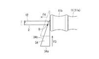
また、前記の筒体移動部材3に代えて、図10,図11に示すような筒体移動部材34を、筒体2の後端とグリップ11のシャフトロック部材11bの先端面との間に挟挿させてもよい。即ち、この筒体移動部材34は楔片からなるものであって、シャフト12が遊嵌される切込み溝34cを楔片の先端(上端)から形成したものである。 Further, instead of the
かかる筒体移動部材34の下端面34aを力点とし、シャフト12と直交する方向の力F3を加えて、筒体移動部材34を筒体2の後端とシャフトロック部材11bの先端面との間に挟挿すると、筒体移動部材34の斜面34bと筒体2の後端との当接部Qにおいて、上記力F3が筒体2をシャフト12の先端方向に移動させる力F4に変換されて筒体2に作用するため、筒体2を回転させないでシャフト12の先端方向に移動させることができる。 Using the
なお、図9,図10に示す筒体移動部材33,34は、いずれも筒体2の後端とシャフトロック部材11bの先端面との間に挟挿するようにしているが、筒体2の後端近傍部位に前記の鍔状突出部2bを設けて、前記の筒体移動部材3と同様に、鍔状突出部2bとシャフトロック部材11bの先端面との間に挟挿するようにしてもよいことは言うまでもない。 In addition, although the
1 ドライバー本体
11 グリップ
11b シャフトロック部材
12 シャフト
12a シャフト先端の係合軸部
2 筒体
2b 突出部
3,31,32,33,34 筒体移動部材
4 医療用ネジ
4a 被係合孔
P 筒体移動部材とグリップとの当接部
Q 筒体移動部材と筒体との当接部DESCRIPTION OF
Claims (3)
Translated fromJapaneseドライバー本体のシャフトにその長さ方向に移動自在に外挿され、先端が医療用ネジの後端に当接又は近接する筒体と、
ドライバー本体のグリップと筒体の間に設けられ、筒体を回転させないでシャフトの先端方向に移動させる筒体移動部材と、
を備えたことを特徴とする医療用ネジを取付けるためのドライバー。A driver main body formed with an engagement shaft portion to be inserted into and engaged with the engaged hole of the medical screw at the tip of the shaft protruding from the grip;
A cylindrical body that is slidably inserted in the length direction of the shaft of the driver body, and whose tip abuts on or close to the rear end of the medical screw;
A cylinder moving member that is provided between the grip of the driver body and the cylinder, and moves in the tip direction of the shaft without rotating the cylinder;
A screwdriver for attaching a medical screw characterized by comprising:
Priority Applications (1)
| Application Number | Priority Date | Filing Date | Title |
|---|---|---|---|
| JP2013046898AJP5997078B2 (en) | 2013-03-08 | 2013-03-08 | Screwdriver for attaching medical screws |
Applications Claiming Priority (1)
| Application Number | Priority Date | Filing Date | Title |
|---|---|---|---|
| JP2013046898AJP5997078B2 (en) | 2013-03-08 | 2013-03-08 | Screwdriver for attaching medical screws |
Publications (2)
| Publication Number | Publication Date |
|---|---|
| JP2014171673A JP2014171673A (en) | 2014-09-22 |
| JP5997078B2true JP5997078B2 (en) | 2016-09-21 |
Family
ID=51693603
Family Applications (1)
| Application Number | Title | Priority Date | Filing Date |
|---|---|---|---|
| JP2013046898AActiveJP5997078B2 (en) | 2013-03-08 | 2013-03-08 | Screwdriver for attaching medical screws |
Country Status (1)
| Country | Link |
|---|---|
| JP (1) | JP5997078B2 (en) |
Families Citing this family (9)
| Publication number | Priority date | Publication date | Assignee | Title |
|---|---|---|---|---|
| JP6271363B2 (en)* | 2014-07-23 | 2018-01-31 | 帝人メディカルテクノロジー株式会社 | Medical screwdriver |
| US10856966B2 (en) | 2014-10-23 | 2020-12-08 | Medos International Sarl | Biceps tenodesis implants and delivery tools |
| US10751161B2 (en) | 2014-10-23 | 2020-08-25 | Medos International Sárl | Biceps tenodesis anchor implants |
| US10034742B2 (en) | 2014-10-23 | 2018-07-31 | Medos International Sarl | Biceps tenodesis implants and delivery tools |
| US10076374B2 (en) | 2014-10-23 | 2018-09-18 | Medos International Sárl | Biceps tenodesis delivery tools |
| US10729419B2 (en) | 2014-10-23 | 2020-08-04 | Medos International Sarl | Biceps tenodesis implants and delivery tools |
| US9693856B2 (en) | 2015-04-22 | 2017-07-04 | DePuy Synthes Products, LLC | Biceps repair device |
| US10231824B2 (en) | 2016-04-08 | 2019-03-19 | Medos International Sárl | Tenodesis anchoring systems and tools |
| US10231823B2 (en) | 2016-04-08 | 2019-03-19 | Medos International Sarl | Tenodesis implants and tools |
Family Cites Families (4)
| Publication number | Priority date | Publication date | Assignee | Title |
|---|---|---|---|---|
| JPS5541261U (en)* | 1978-09-08 | 1980-03-17 | ||
| JP3119826B2 (en)* | 1996-11-28 | 2000-12-25 | グンゼ株式会社 | Screw fastening tool |
| JP2000033582A (en)* | 1998-07-21 | 2000-02-02 | Daiden Co Ltd | Cable terminal pulling out device |
| JP4271300B2 (en)* | 1999-07-05 | 2009-06-03 | グンゼ株式会社 | Medical screwdriver |
- 2013
- 2013-03-08JPJP2013046898Apatent/JP5997078B2/enactiveActive
Also Published As
| Publication number | Publication date |
|---|---|
| JP2014171673A (en) | 2014-09-22 |
Similar Documents
| Publication | Publication Date | Title |
|---|---|---|
| JP5997078B2 (en) | Screwdriver for attaching medical screws | |
| US20110238069A1 (en) | Threaded hole forming device | |
| KR101433683B1 (en) | Transbuccal plate holding cannula | |
| EP1124488B1 (en) | Rongeur | |
| US9763675B2 (en) | Angled instrument assembly | |
| JP2005531364A5 (en) | ||
| EP3160687B1 (en) | Screwdriver | |
| JP2007532191A5 (en) | ||
| CN105050518A (en) | Bone Screws and Self-Retaining Drivers | |
| GB2563494A (en) | Inserter with impact and rotational drive advancement and implant holder with implant auto release | |
| RU2013119871A (en) | SYSTEM USED IN TISSUE RECOVERY | |
| EP1886635A4 (en) | STENT DEPLOYMENT APPARATUS | |
| JP2013509921A5 (en) | ||
| EP4509068A3 (en) | Adjustable drilling device | |
| US10045787B2 (en) | Orthopedic device holder system | |
| JP2017506983A (en) | Two-part knotless suture anchor | |
| US6066143A (en) | Pin puller | |
| US20190083147A1 (en) | Instrument assembly for use with an expandable pedicle screw | |
| US11331134B2 (en) | Orthopedic device holder | |
| JP4271300B2 (en) | Medical screwdriver | |
| JP3804801B2 (en) | Hook remover | |
| JP6366065B2 (en) | Sliding hammer | |
| JP2008264565A (en) | Ultrasonic treatment apparatus | |
| JP4633139B2 (en) | Torque Wrench | |
| FR2902311A1 (en) | Surgical drilling instrument for installing endo-osseous implant, has perforator with assembling zone composed of cooperating zone extended towards shank by receiving zone that is delimited between proximal and distal stops |
Legal Events
| Date | Code | Title | Description |
|---|---|---|---|
| A621 | Written request for application examination | Free format text:JAPANESE INTERMEDIATE CODE: A621 Effective date:20151015 | |
| RD02 | Notification of acceptance of power of attorney | Free format text:JAPANESE INTERMEDIATE CODE: A7422 Effective date:20151212 | |
| TRDD | Decision of grant or rejection written | ||
| A01 | Written decision to grant a patent or to grant a registration (utility model) | Free format text:JAPANESE INTERMEDIATE CODE: A01 Effective date:20160809 | |
| A61 | First payment of annual fees (during grant procedure) | Free format text:JAPANESE INTERMEDIATE CODE: A61 Effective date:20160825 | |
| R150 | Certificate of patent or registration of utility model | Ref document number:5997078 Country of ref document:JP Free format text:JAPANESE INTERMEDIATE CODE: R150 | |
| S533 | Written request for registration of change of name | Free format text:JAPANESE INTERMEDIATE CODE: R313533 | |
| R350 | Written notification of registration of transfer | Free format text:JAPANESE INTERMEDIATE CODE: R350 | |
| S111 | Request for change of ownership or part of ownership | Free format text:JAPANESE INTERMEDIATE CODE: R313111 | |
| R350 | Written notification of registration of transfer | Free format text:JAPANESE INTERMEDIATE CODE: R350 |