JP5994804B2 - Substrate cleaning method - Google Patents
Substrate cleaning methodDownload PDFInfo
- Publication number
- JP5994804B2 JP5994804B2JP2014053800AJP2014053800AJP5994804B2JP 5994804 B2JP5994804 B2JP 5994804B2JP 2014053800 AJP2014053800 AJP 2014053800AJP 2014053800 AJP2014053800 AJP 2014053800AJP 5994804 B2JP5994804 B2JP 5994804B2
- Authority
- JP
- Japan
- Prior art keywords
- substrate
- cleaning liquid
- nozzle
- wafer
- cleaning
- Prior art date
- Legal status (The legal status is an assumption and is not a legal conclusion. Google has not performed a legal analysis and makes no representation as to the accuracy of the status listed.)
- Active
Links
Images


Landscapes
- Exposure Of Semiconductors, Excluding Electron Or Ion Beam Exposure (AREA)
- Cleaning Or Drying Semiconductors (AREA)
Description
Translated fromJapanese 本発明は、表面が疎水性である基板例えば液浸露光に用いられるレジストが塗布された基板、あるいは液浸露光後に更に現像処理された基板などの表面を洗浄する基板洗浄方法に関する。
The present invention, surface aboutthe substrate cleaninghow the substrate a resist used in the immersion exposure is cleaning a surface such as a substrate which has been further developed after the substrates or immersion exposure, the coating is hydrophobic.
従来、半導体製造工程の一つであるフォトレジスト工程においては、基板である半導体ウエハ(以下、ウエハという)の表面にレジストを塗布し、露光後に、現像してレジストパターンを作成しており、このような処理は、一般にレジストの塗布・現像を行う塗布・現像装置に、露光装置を接続したシステムを用いて行われる。 Conventionally, in a photoresist process, which is one of semiconductor manufacturing processes, a resist is applied to the surface of a semiconductor wafer (hereinafter referred to as a wafer), which is a substrate, and developed after exposure to create a resist pattern. Such a process is generally performed using a system in which an exposure apparatus is connected to a coating / developing apparatus for coating and developing a resist.
このような一連の処理の中で、現像処理においてはウエハ上に現像液を液盛りし、その後例えば所定時間ウエハを静止した状態とし、レジストの溶解性部位を溶解させてパターンが形成される。そしてレジストの溶解物を現像液と共にウエハ表面から除去するために洗浄処理が行われるが、その手法としては従来からウエハの中心部に洗浄液を供給し、その遠心力により液膜を広げ、その液流に載せて前記溶解物及び現像液をウエハ上から除去することが行われている。 In such a series of processes, in the development process, a developer is deposited on the wafer, and after that, for example, the wafer is kept stationary for a predetermined time, and the soluble portion of the resist is dissolved to form a pattern. A cleaning process is performed to remove the dissolved resist together with the developer from the wafer surface. Conventionally, a cleaning solution is supplied to the center of the wafer, and the liquid film is expanded by the centrifugal force. The melt and the developer are removed from the wafer by placing them in a flow.
しかしこのスピン洗浄は、溶解生成物を十分に取り除くことができず、パターンの線幅が広いときには問題視されてこなかったが、線幅が狭くなってくると、残留した溶解生成物が現像欠陥として現れる度合いが強くなる。このためスピン洗浄を例えば60秒もの長い時間行うようにしているのが現状である。またこのように長く洗浄を行っても、やはり溶解生成物の取り残しがあり、十分な洗浄ができているとは言い難い場合もある。 However, this spin cleaning cannot remove the dissolved product sufficiently and has not been regarded as a problem when the line width of the pattern is wide. However, when the line width becomes narrower, the remaining dissolved product becomes a development defect. The degree that appears as becomes stronger. For this reason, the present situation is that the spin cleaning is performed for as long as 60 seconds, for example. Even if washing is performed for such a long time, the dissolved product is still left behind, and it may be difficult to say that sufficient washing is performed.
そこで本件出願人は、ウエハを回転させながら洗浄液ノズルからウエハの中心部に洗浄液を吐出し、次いで洗浄液ノズルをウエハの外方側に少し移動させ、ウエハの中心部にガスノズルからN2ガスを吐出して乾燥領域のコアを形成し、次いでこの乾燥領域に追いつかれないように洗浄液ノズルを、洗浄液を吐出しながらウエハの外方側に移動させる手法を提案している(特許文献1)。この方法によれば高い洗浄効果が得られ、短時間で洗浄できる利点がある。 Therefore, the applicant of the present application discharges the cleaning liquid from the cleaning liquid nozzle to the center of the wafer while rotating the wafer, and then moves the cleaning liquid nozzle slightly to the outer side of the wafer to discharge N2 gas from the gas nozzle to the center of the wafer. A method is proposed in which the core of the dry region is formed, and then the cleaning liquid nozzle is moved to the outer side of the wafer while discharging the cleaning liquid so as not to catch up with the dry region (Patent Document 1). According to this method, there is an advantage that a high cleaning effect can be obtained and cleaning can be performed in a short time.
一方、デバイスパターンは益々微細化、薄膜化が進む傾向にあり、これに伴い露光の解像度を上げる要請が強まっている。そこで既存の光源例えばフッ化アルゴン(ArF)やフッ化クリプトン(KrF)による露光技術を更に改良して解像度を上げるため、基板の表面に光を透過させる液相を形成した状態で露光する手法(以下「液浸露光」という。)の検討がされている。液浸露光は例えば超純水の中を光を透過させる技術であり、水中では波長が短くなることから193nmのArFの波長が水中では実質134nmになる、という特徴を利用するものである。 On the other hand, device patterns are becoming increasingly finer and thinner, and with this trend, there is an increasing demand for higher exposure resolution. In order to improve the resolution by further improving the exposure technique using an existing light source such as argon fluoride (ArF) or krypton fluoride (KrF), exposure is performed in a state where a liquid phase that transmits light is formed on the surface of the substrate ( Hereinafter, “immersion exposure” is being studied. Immersion exposure is a technique that allows light to pass through, for example, ultrapure water, and uses the feature that the wavelength of ArF at 193 nm is substantially 134 nm in water because the wavelength is shorter in water.
このような液浸露光の課題の一つとして、ウエハに水滴が残留した状態で露光装置から塗布、現像装置に搬送される可能性が挙げられる。露光後のウエハWは熱処理が行われるが、ウエハ上に水滴があると、あるいはその水滴が乾燥して水の浸みであるいわゆるウオータマークが生成されると、その直下のパターン解像に悪影響がある。このため露光後のウエハの表面を洗浄して水滴を除去する必要がある。 One of the problems of such immersion exposure is the possibility that water droplets remain on the wafer and are transferred from the exposure apparatus to the coating and developing apparatus. The exposed wafer W is heat-treated, but if there are water droplets on the wafer, or if the water droplets are dried and a so-called water mark is formed, which is a soaking of water, the pattern resolution directly underneath is adversely affected. There is. For this reason, it is necessary to clean the surface of the wafer after exposure to remove water droplets.
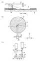
また液浸露光プロセスにおいては、露光機液浸部(レンズ先端)のスキャン追随性を高めて従来からの露光装置と同等のスループットを確保するために、露光ウエハ表面に撥水性の高い、例えば水の静的接触角が75〜85度程度の保護膜を形成することが検討されているが、保護膜の撥水性が高いだけに保護膜の表面に小さな水滴が残留する可能性が大きくなってくる。なお前記水の静的接触角とは、図25に示すように水滴が基板の表面に付着しているときに水滴を断面で見たときに水滴の外縁を形成する円弧について、基板の表面における接線と当該表面とのなす角度θである。また、水の静的接触角は、現像処理することで低下することがある。以下、単に接触角という記載は静的接触角のことであり、さらに現像処理前の水の静的接触角を示すものとする。 Also, in the immersion exposure process, the surface of the exposed wafer has a high water repellency, for example, water, in order to improve the scan followability of the exposure unit immersion part (lens tip) and ensure the same throughput as the conventional exposure apparatus. It has been studied to form a protective film having a static contact angle of about 75 to 85 degrees. However, since the water repellency of the protective film is high, there is a high possibility that small water droplets remain on the surface of the protective film. come. Note that the static contact angle of water refers to an arc that forms the outer edge of a water droplet when the water droplet is viewed in cross section when the water droplet is attached to the surface of the substrate, as shown in FIG. The angle θ between the tangent line and the surface. In addition, the static contact angle of water may be lowered by development processing. Hereinafter, the description simply referred to as a contact angle is a static contact angle, and further indicates a static contact angle of water before development processing.
そして露光機液浸部をスキャンするため、基板の表面にパーティクルが残存していると、このパーティクルが露光機液浸部の下方側の液体中に取り込まれ、各スキャン位置において当該パーティクルに基づく現像欠陥が発生するため、液浸露光に入る前にウエハ表面を洗浄してパーティクルを確実に除去する必要がある。しかしながら特許文献1の手法においては、ウエハの表面の接触角が高いとつまり表面の撥水性が高いと、ウエハの中心付近から離れた領域においてパーティクル(液浸露光前)あるいは水滴(液浸露光後)を十分に除去することが困難である。 Then, if particles remain on the surface of the substrate to scan the exposure unit immersion part, the particles are taken into the liquid below the exposure unit immersion part, and development based on the particles at each scanning position Since defects occur, it is necessary to cleanly remove the particles by cleaning the wafer surface before entering the immersion exposure. However, in the method of
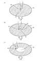
その理由は、図26(a)に示すようにウエハWの中心に洗浄液ノズル11から洗浄液Rを吐出してウエハWの全面に行き渡らせ、次いで図26(b)に示すようにガスノズル12からのN2ガスの吐出によりウエハWの中心部に乾燥領域のコアを形成したときに、ウエハWの表面の撥水性が高いことから、薄い液膜が外に向かってかなり早い速度で移動し、このためこの薄い液膜が引きちぎれて水滴Mとなって残留してしまう。なおウエハWの中心に近い領域では、はじめにウエハWの中心部に洗浄液Rが吐出されかつこの領域の遠心力が小さいことから、洗浄効果が高く、水滴の残留は実質起こらない。 The reason for this is that the cleaning liquid R is discharged from the cleaning
また、前記保護膜を使用せずに更に撥水性の高い(疎水性の大きい)レジスト膜(水の静的接触角が85度以上)を用いることが検討されている。このようなレジストを用いた場合には、現像後においてもウエハの表面の撥水性が高く、特許文献1の手法では次のような問題がある。 In addition, it has been studied to use a resist film (having a static contact angle of water of 85 degrees or more) with higher water repellency (higher hydrophobicity) without using the protective film. When such a resist is used, the water repellency of the wafer surface is high even after development, and the method of
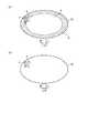
ウエハの表面の撥水性がそれほど高くない場合つまり水の接触角がそれほど大きくない場合には、ウエハ中心部に洗浄液を吐出して全面に広げた後、乾燥コアを形成して広げるときに、図27(a)に示すように、レジストパターンの凹部13内に残存する洗浄液Rが凹部13の外のパターン表面に沿ってウエハ外方に向かう洗浄液に引き連れられ、当該凹部13から洗浄液が排出される。これに対して、ウエハの表面における水の接触角が85度にもなると、前記乾燥コアの広がり速度がかなり速くなり、即ちパターン表面上の薄い液膜がウエハ外方に向かう速度がかなり速くなり、図27(b)に示すように、凹部13内の洗浄液Rが前記液膜から引きちぎられて当該凹部13内に取り残されることとなる。この洗浄液R中にはレジストの溶解生成物が含まれるため、現像欠陥の要因となる。この現像欠陥は、既述した理由からウエハの中心に近い領域ではほとんど発生しないが、当該領域の外側において顕著に発生する。 When the water repellency of the wafer surface is not so high, that is, when the contact angle of water is not so large, after the cleaning liquid is discharged to the center of the wafer and spread over the entire surface, a dry core is formed and spread. As shown in FIG. 27 (a), the cleaning liquid R remaining in the
また特許文献2には、処理液ノズルをウエハの中心から10mm〜15mm離れた位置へ急速移動し、その後に速やかにウエハの中心部にN2ノズルからN2ガスを吹付けてウエハの中心部の乾燥を促進し、処理液ノズルをウエハの周縁に3mm/秒以下の速度でスキャンさせる洗浄方法が記載されている。しかしながらこの特許文献2には、ウエハの表面が85度以上もの大きな接触角を有している場合に、ウエハの中心部近傍から周縁に亘って確実に表面を洗浄できる技術は記載されていない。具体的には、洗浄液ノズルとガスノズルとの大きさによっては、乾燥域をうまく形成できない事、あるいはノズル移動速度が遅く、プロセス時間が長くなるといった課題が発生する。
本発明はこのような事情の下になされたものであり、高い洗浄効果を得ることが出来、しかも短時間で洗浄を行うことのできる技術を提供することにある。
The present invention has been made under suchcircumstances, it is to provide a technique which can obtain a cleaning effect hasa high, yet can be cleaned in a short time.
本発明の基板洗浄方法は、撥水性を有する基板の表面の洗浄および乾燥を行う基板洗浄方法であって、
基板を略水平に保持しつつ基板に垂直な軸の周りで回転させる工程と、
洗浄液を吐出する洗浄液ノズルを用いて回転する基板上の中心部に洗浄液を供給して液膜を形成する工程と、
前記洗浄液ノズルから吐出された洗浄液を受ける基板上の位置が前記回転する基板上の中心部から基板上の周縁部に向かって一定距離移動するように前記洗浄液ノズルを移動させる工程と、
前記洗浄液を受ける基板上の位置が基板上の中心部から一定距離離間した状態を保持しつつ、気体を吐出するガスノズルを用いて前記回転する基板上の中心部に所定時間気体を吐出することにより基板上の中心部に乾燥領域を形成する工程と、
基板上の中心部に乾燥領域が形成された後、前記洗浄液を受ける基板上の位置が前記回転する基板上の周縁部に向かって連続的に移動するように10mm/秒を越えない速度で前記洗浄液ノズルを移動させるとともに、前記ガスノズルから吐出された気体を受ける基板上の位置が前記洗浄液を受ける基板上の位置から前記一定距離離間しつつ前記洗浄液を受ける基板上の位置の移動経路をたどるように前記ガスノズルを連続的に移動させる工程と、
を備え、
前記洗浄液ノズル及び前記ガスノズルを連続的に移動させる工程は、前記中心部に気体が吐出されて形成された前記乾燥領域が瞬時に前記洗浄液の吐出される位置まで到達して前記基板上に洗浄液の液膜と乾燥領域との界面を形成し、当該界面が形成された状態で前記洗浄液の吐出位置を前記乾燥領域が基板の外側に広がる速度よりも遅い速度で基板の周縁部に向かって移動させるように、洗浄液ノズルの移動速度、洗浄液の吐出流量及び基板の回転数が制御される工程と、前記洗浄液の各吐出位置における前記基板の回転による遠心力が一定となるように前記基板の回転数を制御する工程と、
を含み、
前記一定距離は、9mm以上15mm以下であり、
前記洗浄液ノズルと共にガスノズルを移動させる工程は、前記洗浄液を受ける基板上の位置が、基板周縁部から2mm〜10mm離れた位置に移動するように行われ、
洗浄液を受ける基板上の位置が前記基板周縁部から離れた位置に移動したときに、基板を回転させながら前記洗浄液の吐出を停止する工程と、
前記洗浄液の吐出停止後に、遠心力により前記基板上の洗浄液を基板から除去するために引き続き基板を回転させる工程と、
を備え、
前記洗浄液を受ける基板上の位置が基板上の中心部から基板上の周縁部に向かって一定距離移動するように前記洗浄液ノズルを移動させる工程は、基板を1500rpm〜2000rpmで回転させながら行うことを特徴とすることを特徴とする。
The substrate cleaning method of the present invention is a substrate cleaning methodfor cleaning and drying thesurface of a substrate having water repellency,
Rotating around an axis perpendicular to the substrate while holding the substrate substantially horizontal;
Supplying a cleaning liquid to a central portion on a rotating substrate using a cleaning liquid nozzle for discharging the cleaning liquid to form a liquid film;
Moving the cleaning liquid nozzle so that a position on the substrate that receives the cleaning liquid discharged from the cleaning liquid nozzle moves from the central part on the rotating substrate toward a peripheral part on the substrate by a certain distance;
By discharging a gas to the central portion on the rotating substrate for a predetermined time using a gas nozzle that discharges the gas while maintaining a state where the position on the substrate that receives the cleaning liquid is separated from the central portion on the substrate by a certain distance. Forming a dry region in the center of the substrate;
After a dry region is formed at the center on the substrate, the position on the substrate that receives the cleaning liquid moves at aspeed not exceeding 10 mm / second so that the position on the substrate continuously moves toward the peripheral edge on the rotating substrate. The cleaning liquid nozzle is moved, and the position on the substrate that receives the gas discharged from the gas nozzle follows the moving path of the position on the substrate that receives the cleaning liquid while being spaced apart from the position on the substrate that receives the cleaning liquid by the predetermined distance. Continuously moving the gas nozzle to
With
In the step of continuously moving the cleaning liquid nozzle and the gas nozzle, the dry region formed by discharging gas to the central portion instantaneously reaches a position where the cleaning liquid is discharged and the cleaning liquid is formed on the substrate. An interface between the liquid film and the dry region is formed, and the cleaning liquid discharge position is moved toward the peripheral edge of the substrate at a speed slower than the speed at which the dry region spreads outside the substrate with the interface formed. As described above, the movement speed of the cleaning liquid nozzle, the discharge flow rate of the cleaning liquid, and the rotation speed of the substrate are controlled, and the rotation speed of the substrate so that the centrifugal force due to the rotation of the substrate at each discharge position of the cleaning liquid is constant. Controlling the process,
Only including,
The certain distance is 9 mm or more and 15 mm or less,
The step of moving the gas nozzle together with the cleaning liquid nozzle is performed such that the position on the substrate that receives the cleaning liquid moves to a
Stopping the discharge of the cleaning liquid while rotating the substrate when the position on the substrate for receiving the cleaning liquid moves to a position away from the peripheral edge of the substrate;
A step of continuously rotating the substrate in order to remove the cleaning solution on the substrate from the substrate by centrifugal force after stopping the discharge of the cleaning solution;
With
The step of moving the cleaning liquid nozzle so that the position on the substrate that receives the cleaning liquid moves a certain distance from the central portion on the substrate toward the peripheral portion on the substrate is performed while rotating the substrate at 1500 rpm to 2000 rpm. It is a characteristic.
例えば基板を回転させる工程は、前記洗浄液を受ける基板上の位置が基板上の中心部に位置する状態で基板が第1の回転速度で回転し、前記洗浄液を受ける基板上の位置が基板上の周縁に位置する状態で基板が前記第1の回転速度より低い第2の回転速度で回転するように基板の回転速度を段階的または連続的に変化させる工程を含む。 For example, in the step of rotating the substrate, the substrate rotates at a first rotational speed in a state where the position on the substrate that receives the cleaning liquid is located at the center of the substrate, and the position on the substrate that receives the cleaning liquid is on the substrate. A step of changing the rotation speed of the substrate stepwise or continuously so that the substrate rotates at a second rotation speed lower than the first rotation speed while being positioned at the periphery.
前記一定距離は、例えば9mm以上15mm以下である。The fixed distance is, for example, 9 mm or more and 15 mm or less.
前記洗浄ノズルと共にガスノズルを移動させる工程は、洗浄液を受ける基板上の位置が基板周縁部から2mm〜10mm離れた位置に移動するように行われ、The step of moving the gas nozzle together with the cleaning nozzle is performed such that the position on the substrate that receives the cleaning liquid moves to a
洗浄液を受ける基板上の一が前記基板周縁部から離れた位置に移動したときに、基板を回転させながら前記洗浄液の吐出を停止する工程と、 A step of stopping the discharge of the cleaning liquid while rotating the substrate when one on the substrate that receives the cleaning liquid moves to a position away from the peripheral edge of the substrate;
前記洗浄液の吐出停止後に、遠心力により前記基板上の洗浄液を基板から除去するために引き続き基板を回転させる工程と、A step of continuously rotating the substrate in order to remove the cleaning solution on the substrate from the substrate by centrifugal force after stopping the discharge of the cleaning solution;
を備えている。It has.
前記洗浄ノズルから吐出された洗浄液を受ける基板上の位置が基板上の中心部から基板上の周縁に向かって一定距離移動するように前記洗浄ノズルを移動させる工程は、The step of moving the cleaning nozzle so that the position on the substrate that receives the cleaning liquid discharged from the cleaning nozzle moves a certain distance from the central portion on the substrate toward the periphery on the substrate,
例えば基板を1500rpm〜2000rpmで回転させながら行う。For example, it is performed while rotating the substrate at 1500 rpm to 2000 rpm.
前記乾燥領域を形成するために基板上の中心部に気体を供給する前記所定時間は例えば0.5秒間である。 The predetermined time for supplying the gas to the central portion on the substrate to form the dry region is, for example, 0.5 seconds.
ところで、基板に現像液を供給する現像処理後に洗浄を行う場合、基板における水の静的接触角が85度以上とは、現像処理前の基板における水の静的接触角が85度以上であることを示す。現像液によってレジストの表面の状態が変わるなどの原因から、現像処理前に水の静的接触角が85度以上であった基板表面については、洗浄時にその静的接触角が85度よりも多少低くなっていることがあるが、この場合における洗浄処理は現像処理を行った直後に行う必要があるため、現像処理後洗浄処理前の静的接触角を正確に測定することが難しいので、このように静的接触角を定義する。 By the way, when cleaning is performed after the development process for supplying the developer to the substrate, the static contact angle of water on the substrate is 85 degrees or more means that the static contact angle of water on the substrate before the development process is 85 degrees or more. It shows that. For the substrate surface where the static contact angle of water was 85 degrees or more before the development processing due to the change of the resist surface state depending on the developer, the static contact angle is slightly more than 85 degrees during cleaning. However, since it is difficult to accurately measure the static contact angle after the development process and before the cleaning process, the cleaning process in this case must be performed immediately after the development process. Define the static contact angle as follows:
本発明によれば、回転する基板上の中心部にガスノズルから気体を吐出して乾燥領域を形成し、瞬時に乾燥領域を洗浄液の吐出される位置まで到達させて洗浄液の液膜と乾燥領域との界面を形成する。そして、洗浄液を受ける基板上の位置が基板上の周縁に向かって連続的に移動するように洗浄ノズルを移動させるとともに、前記ガスノズルから吐出された気体を受ける基板上の位置が前記洗浄液を受ける基板上の位置から一定距離離間しつつ前記洗浄液を受ける基板上の位置の移動経路をたどるように前記ガスノズルを連続的に移動させる。これによって、高い洗浄効果を得ることができ、しかも洗浄を短時間で行うことができる。そして特に露光された基板の表面に現像液を供給して現像を行った後の基板に対して本発明を適用すれば、後述の評価試験からも明らかなように現像欠陥を皆無に近い状態まで低減することができ、歩留まりの向上に大きく寄与する。
また、形成された乾燥領域に、処理雰囲気からノズルに付着した液滴が落下することを抑えることで、現像欠陥をより確実に低減することができる。
According to the present invention, a gas is ejected from a gas nozzle to the central portion on a rotating substrate to form a dry region, and the dry region is instantaneously reached to a position where the cleaning liquid is discharged, and the cleaning liquid film and the dry region are formed. The interface is formed. Then, the cleaning nozzle is moved so that the position on the substrate that receives the cleaning liquid continuously moves toward the peripheral edge on the substrate, and the position on the substrate that receives the gas discharged from the gas nozzle is the substrate that receives the cleaning liquid. The gas nozzle is continuously moved so as to follow a movement path of a position on the substrate that receives the cleaning liquid while being spaced apart from the upper position by a certain distance. As a result, a high cleaning effect can be obtained, and cleaning can be performed in a short time. In particular, if the present invention is applied to the substrate after the development is performed by supplying the developer to the exposed surface of the substrate, it is almost impossible to develop defects as will be apparent from the evaluation test described later. This can be reduced and greatly contributes to the improvement of yield.
In addition, development defects can be more reliably reduced by preventing the droplets attached to the nozzles from dropping from the processing atmosphere to the formed dry region.
[第1の実施の形態]
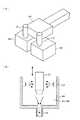
本発明の基板洗浄装置を現像装置に組み合わせた実施の形態について説明する。図1において、2は基板例えばウエハWの裏面側中央部を吸引吸着して水平姿勢に保持するための基板保持部であるスピンチャックである。スピンチャック2は回転軸21を介して回転機構を含む駆動機構22と接続されており、ウエハWを保持した状態で回転及び昇降可能なように構成されている。なお、本例では、スピンチャック2の回転軸21上にウエハWの中心が位置するように設定されている。[First embodiment]
An embodiment in which the substrate cleaning apparatus of the present invention is combined with a developing apparatus will be described. In FIG. 1,
スピンチャック2上のウエハWを囲むようにして上方側が開口するカップ3体が設けられている。このカップ体3は、上部側が四角状であり下部側が円筒状の外カップ31と、上部側が内側に傾斜した筒状の内カップ32とからなり、外カップ31の下端部に接続された昇降部33により外カップ31が昇降し、更に内カップ32は外カップ31の下端側内周面に形成された段部に押し上げられて昇降可能なように構成されている。 Three cups having an upper opening are provided so as to surround the wafer W on the
またスピンチャック2の下方側には円形板34が設けられており、この円形板34の外側には断面が凹部状に形成された液受け部35が全周に亘って設けられている。液受け部35の底面にはドレイン排出口36が形成されており、ウエハWからこぼれ落ちるか、あるいは振り切られて液受け部35に貯留された現像液や洗浄液はこのドレイン排出口36を介して装置の外部に排出される。また円形板34の外側には断面山形のリング部材37が設けられている。なお、図示は省略するが、円形板34を貫通する例えば3本の基板支持ピンである昇降ピンが設けられており、この昇降ピンと図示しない基板搬送手段との協働作用によりウエハWはスピンチャック2に受け渡しされるように構成されている。 A
更に本例の現像装置(基板洗浄装置を兼用)は、現像液ノズル23、洗浄液ノズル4及びガスノズル5を備えている。現像液ノズル23は、スピンチャック2に保持されたウエハWの直径方向に伸びる帯状の吐出口例えばスリット状の吐出口23a(図2参照)を備えている。このノズル23は現像液供給路24例えば配管を介して現像液供給系25に接続されている。この現像液供給系25は、現像液供給源、供給制御機器などを含むものである。 Further, the developing device of this example (also used as a substrate cleaning device) includes a developing
前記現像液ノズル23は支持部材であるノズルアーム26の一端側に支持されており、このノズルアーム26の他端側は図示しない昇降機構を備えた移動基体27と接続されており、更に移動基体27は例えばユニットの外装体底面にてX方向に伸びるガイド部材28に沿って、昇降機構と共に移動機構をなす図示しない駆動源により横方向に移動可能なように構成されている。また図中29は現像液ノズル23の待機部であり、このノズル待機部29でノズル先端部の洗浄などが行われる。 The
洗浄液ノズル4は吐出口40(図4参照)を有し、洗浄液供給路42例えば配管を介して洗浄液供給系43に接続されている。この洗浄液供給系43は、洗浄液供給源、供給制御機器などを含むものであり、供給制御機器は、吐出流量可能なポンプ及びバルブなどを備えている。更に洗浄液ノズル4は図3に示すようにノズル保持部41を介してノズルアーム44に固定されており、このノズルアーム44は昇降機構を備えた移動基体45と接続されている。この移動基体45は昇降機構と共に移動機構をなす図示しない駆動源により例えば前記ガイド部材28に沿って現像液ノズル23と干渉しないで横方向に移動可能なように構成されている。また図中46は洗浄液ノズル4の待機部である。 The cleaning
ガスノズル5は、配管を介してガス供給系に接続されており、この例ではガス供給系は不活性ガスであるN2(窒素)ガス供給源、供給制御機器などを含む。またガスノズル5は、例えばノズル保持部41に固定されており、ノズルアーム44により洗浄液ノズル4と一緒に移動するように構成されている。 The
続いて洗浄液ノズル4とガスノズル5との離間位置について、洗浄液R及びN2ガスが吐出された状態を示した図4を用いて説明する。図中4A、5Aは洗浄液ノズル4の吐出口40、ガスノズル5の吐出口50からウエハWに夫々吐出された洗浄液吐出(供給)位置、ガス吐出(供給)位置を示している。また、この洗浄液吐出位置4Aは吐出口40の洗浄液の吐出方向に向かったウエハWへの投影領域であり、ガス吐出位置5Aは、吐出口50のガスの吐出方向に向かったウエハWへの投影領域である。洗浄液吐出位置4Aのガス吐出位置5A側界面と、ガスの吐出位置4Aの洗浄液吐出位置側5A側界面との距離dは9mm〜15mmであり、後述するように上述の距離dは12.35mmであるときに最も好ましく、本実施形態ではこの大きさに各吐出口が設定されているものとする。また、この例においては洗浄液ノズル4の吐出口40の口径は4.3mmであり、ガスノズル5の吐出口50の口径は1.0mmである。また、洗浄液の供給位置の中心とガスの供給位置の中心との距離d1は15mmである。 Next, the separation position between the cleaning
更に図中5はコンピュータからなる制御部であり、この制御部7は、この現像装置が行う後述の動作における各ステップを実行するためのプログラムを備えていて、現像液供給系25、現像液ノズル23を移動させるための移動機構、洗浄液供給系43、洗浄液ノズル4を移動させるための移動機構、スピンチャック2を駆動する駆動機構22及びカップ32の昇降部33などを制御するための制御信号を、前記プログラムに基づいて出力するように構成されている。またこのプログラムは、ハードディスク、コンパクトディスク、フラッシュメモリ、フレキシブルディスク、メモリカードなどの記憶媒体に格納され、これら記憶媒体からコンピュータにインストールされて使用される。 Further, in the figure,
続いて、上記現像装置を用いて基板であるウエハWを現像し、その後洗浄する一連の工程について説明する。先ず、外カップ31、内カップ32が下降位置にあり、現像液ノズル23、洗浄液ノズル4及びガスノズル5が所定の待機位置にて夫々待機している状態において、その表面にレジストが塗布され、更に液浸露光された後のウエハWが図示しない基板搬送手段により搬入されると、この基板搬送手段と図示しない昇降ピンとの協働作用によりウエハWはスピンチャック2に受け渡される。この例では、レジストとして高い撥水性の材質が用いられ、このためウエハWの表面の水の静的接触角は例えば90度である。 Next, a series of steps for developing the wafer W, which is a substrate, using the developing device and then cleaning the wafer W will be described. First, in a state where the
次いで、外カップ31及び内カップ32が上昇位置に設定されると共に、現像液ノズル23からウエハW上に現像液が供給され、公知の手法により現像液の供給が行われる。この例では例えば現像液ノズル23の吐出口23aをウエハWの表面から数mm高い位置に設定し、しかる後、ウエハWを例えば1000〜1200rpmの回転速度で回転させると共に、吐出口23aから現像液Dを帯状に吐出しながら現像液ノズル23をウエハWの回転半径方向、つまりウエハWの外側から中央側に向かって移動させる。吐出口23aから帯状に吐出された現像液Dは、例えば図5に模式的に示すように、ウエハWの外側から内側に向かって互いに隙間のないように並べられていき、これによりウエハWの表面全体に螺旋状に現像液Dが供給される。そして回転しているウエハWの遠心力の作用によりウエハWの表面に沿って現像液Dは外側に広がり、結果としてウエハWの表面には薄膜状の液膜が形成される。そして現像液Dにレジストの溶解性の部位が溶解して、その後にパターンを形成する不溶解性の部位が残ることとなる。 Next, the
次いでこの現像液ノズル23と入れ替わるようにして洗浄液ノズル4がウエハWの中央部上方に配置され、そして現像液ノズル23が現像液の供給を停止した直後に速やかに洗浄液ノズル4から洗浄液Rを吐出してウエハWの表面の洗浄を行う。以下にこの洗浄工程について図6及び図7を参照しながら詳述すると、この洗浄工程は以下のステップにより行われる。 Next, the cleaning
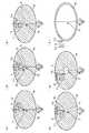
ステップ1: 図6(a)に示すように、洗浄液ノズル4をウエハWの中心部Cに対向しかつウエハWの表面から例えば15mmの高さの位置に設定し、スピンチャック2を例えば1000rpmの回転数で回転させながら、洗浄液ノズル4からウエハWの中心部Cに洗浄液R例えば純水を例えば250ml/分の流量で例えば5秒間吐出する。これにより洗浄液Rが遠心力によりウエハWの中心部Cから周縁に向かって広がり、現像液が洗浄液Rにより洗い流される。なおウエハWの中心部Cとは、ウエハWの中心点及びその近傍を意味する。 Step 1: As shown in FIG. 6A, the cleaning
ステップ2: 次いでスピンチャック2を1500rpm以上例えば2000rpmの回転数で回転させながらノズルアーム44(図2参照)を移動させることにより図6(b)に示すように洗浄液ノズル4をウエハWの中心部Cから少し外側に移動させ、これによりガスノズル5をウエハWの中心部Cと対向するように位置させる。このとき洗浄液ノズル4は、洗浄液Rを例えば250ml/分の流量で吐出しながら例えば150mm/秒の速度で移動する。そしてノズルアーム44は一旦停止し、ガスノズル5はウエハWの中心部Cと対向した直後に当該中心部Cにガス例えば不活性ガスであるN2ガスGを吹き付ける。 Step 2: Next, the nozzle arm 44 (see FIG. 2) is moved while the
洗浄液ノズル4をウエハWの中心部Cから外側に移動させることにより当該中心部Cには洗浄液Rが供給されないが、当該中心部Cは遠心力が小さいので洗浄液Rの液膜が引き裂かれずに薄い状態がしばらく維持される。しかし、図8にも示すようにガスノズル5からN2ガスGが吹付けられることにより液膜が破れ、ウエハWの表面が剥き出しになった乾燥領域6が遠心力により広がっていく。このときウエハWの表面は、水の接触角が90度と撥水性が高いため、乾燥領域6は洗浄液Rが吐出されている位置まで瞬時に広がる。図6(b)の点線は乾燥領域6の周縁を示しており、その中は乾燥領域6であることを示している。また、洗浄液吐出位置4Aのガス吐出位置5A側界面と、ガスの吐出位置4Aの洗浄液吐出位置側5A側界面との距離dが既述のように12.35mmであり、両ノズル4、5が一体的に移動することから、この時点における乾燥領域6はおよそ直径25mmの円形状である。 Although the cleaning liquid R is not supplied to the central portion C by moving the cleaning
ステップ1において洗浄液RはウエハWの中心部Cに吐出され、外に広がることから、当該直径30mmの領域では単位面積あたりの洗浄液Rの量が多く、また遠心力も作用してはいるが、吐出された洗浄液Rが前記中心部Cに衝突しその衝撃により外に広がる作用が大きいことから、洗浄効果が大きい。このため乾燥領域6が瞬時に広がっても既述の図27(b)に示した現象は、後述の評価試験から推察すると皆無といってよく、パターンの凹部内の洗浄液Rは確実に排出されている。 In
ステップ3: 乾燥領域6形成後にガス吐出を終了させ、続いて図6(c)に示すように、ノズルアーム44により洗浄液ノズル4、ガスノズル5が一体的にウエハWの周縁に向けて移動する。乾燥領域6を形成するためのガスの供給開始から停止までの時間は例えば0.5秒である。 Step 3: After the
このステップ3においては、ウエハWが回転している状態で、洗浄液ノズル4から洗浄液Rを吐出している。洗浄液ノズル4の移動速度は、乾燥領域6が外側に広がる速度よりも遅い速度、例えば5mm/秒に設定されている。洗浄液ノズル4によりウエハWの中心部Cに洗浄液を吐出し、その後洗浄液を吐出せずにN2ガスGの吹付けだけを行うと、乾燥領域6が外側に広がっていくが、上記の「乾燥領域6が外側に広がる速度」とはこの場合の速度である。ウエハWの表面の撥水性が高いことから既述のように乾燥領域6の広がる速度が大きく、このため洗浄液ノズル4の移動速度を乾燥領域6の広がる速度よりも大きくすると、図27(b)に示すように洗浄液Rが残留してしまう。またこのステップ3では、図9に示す如く洗浄液Rの各吐出位置においてウエハWの回転による遠心力が計算上一定となるようにウエハWの回転数が制御される。ステップ3の開始時の回転数f1は例えば2000rpmである。 In
このように回転数を制御する理由は、ウエハW上の単位面積当たりに供給する洗浄液Rの量をウエハWの面内で揃え、これによりウエハWの中心部Cから外れた領域においても高い洗浄効果を得ようとするためである。なおこのような効果が得られるのであれば、洗浄液Rの各吐出位置においてウエハWの回転による遠心力が一定でなくとも、洗浄液Rの供給位置がウエハWの中心に近いほどウエハWの回転数が高くなるように、言い換えれば洗浄液Rの供給位置がウエハWの周縁に近いほどウエハWの回転数が低くなるようにウエハWの回転数を制御してもよい。 The reason for controlling the number of revolutions in this way is that the amount of the cleaning liquid R supplied per unit area on the wafer W is made uniform in the plane of the wafer W, so that high cleaning is performed even in a region off the central portion C of the wafer W. This is to obtain an effect. If such an effect can be obtained, the rotation speed of the wafer W becomes closer to the center of the wafer W even if the centrifugal force due to the rotation of the wafer W is not constant at each discharge position of the cleaning liquid R. In other words, the rotational speed of the wafer W may be controlled so that the rotational speed of the wafer W decreases as the supply position of the cleaning liquid R is closer to the periphery of the wafer W.
ステップ3の開始時の回転数f1は例えば2000rpm〜3000rpmであることが好ましく、3000rpmよりも高いとミストなどの問題が発生し、また2000rpmよりも低いと、乾燥領域6の広がるスピードが遅くなり、処理時間が長くなる。またステップ3におけるノズルの移動速度については、処理時間の短縮化を図るためにはできるだけ速い方が好ましいが、あまり速すぎると洗浄効果が低くなることから、10mm/秒を越えないことが好ましい。 The rotation speed f1 at the start of
そして洗浄液ノズル4の中心がウエハWの周縁から少し中心寄りの位置、例えばウエハWの周縁から中心側に2〜10mm離れた位置に達すると(図7(a))、洗浄液ノズル4からの洗浄液Rの吐出を停止し、ウエハWを回転させたままにしておく(図7(b))。なお洗浄液ノズル4からの洗浄液Rの吐出をウエハWの周縁に至るまで行うと、ウエハWの表面に吐出された洗浄液Rが外側に跳ねてミストとなってウエハW表面に舞戻ってくるため、周縁に至る少し手前で洗浄液Rの吐出を停止することが好ましい。なお、洗浄液ノズル4を移動させる工程で、洗浄液と共にガスを吐出させてもよい。この場合、ガスノズル5からのN2ガスGの吐出停止のタイミングについては、洗浄液Rの吐出停止と同じタイミングでもよいが、洗浄液Rの吐出停止前あるいは吐出停止後であってもよい。 When the center of the cleaning
ステップ4: 洗浄液ノズル4の洗浄液Rの吐出を停止した後は、そのままの回転数(この例では2000rpmの回転数)でウエハWを回転させる。これにより乾燥領域6が外側に向かって広がり、乾燥領域6がウエハWの周縁まで広がった後、この例ではウエハWの回転数を2000rpmに設定したままウエハW上の液滴を遠心力により振り切って乾燥を行う。洗浄液ノズル4及びガスノズル5は待機位置に戻される。 Step 4: After stopping the discharge of the cleaning liquid R from the cleaning
なお現像後のウエハWにはパターンである凹部が形成され、この凹部内は親水性になり、ウエハWの表面の接触角が低下する部分がある。本発明の対象は、水の接触角が85度以上である疎水性表面を備えた基板であり、この例では現像処理前の水の静的接触角が85度以上である疎水性表面を備えた基板の洗浄工程を示している。基板に現像液を供給する現像処理後に洗浄を行う場合、基板における水の静的接触角が85度以上とは、現像処理前の基板における水の静的接触角が85度以上であることを示す。現像液によってレジストの表面の状態が変わるなどの原因から、現像処理前に水の静的接触角が85度以上であった基板表面については、洗浄時にそのレジストの静的接触角が85度よりも多少低くなっていることがあるが、この場合における洗浄処理は現像処理を行った直後に行う必要があるため、現像処理後洗浄処理前の静的接触角を正確に測定することが難しいので、このように静的接触角を定義している。 The developed wafer W is formed with a concave portion that is a pattern, and the concave portion becomes hydrophilic, and there is a portion where the contact angle of the surface of the wafer W decreases. The object of the present invention is a substrate having a hydrophobic surface with a water contact angle of 85 degrees or more, and in this example, has a hydrophobic surface with a static contact angle of water of 85 degrees or more before development processing. The substrate cleaning process is shown. When cleaning is performed after the development process for supplying the developer to the substrate, the static contact angle of water on the substrate is 85 degrees or more means that the static contact angle of water on the substrate before the development process is 85 degrees or more. Show. For the substrate surface where the static contact angle of water was 85 degrees or more before the development processing due to the change of the resist surface state depending on the developer, the static contact angle of the resist is more than 85 degrees during cleaning. However, since the cleaning process in this case must be performed immediately after the development process, it is difficult to accurately measure the static contact angle after the development process and before the cleaning process. Thus, the static contact angle is defined.
以上の一連のステップ1〜4は、制御部7のメモリ内に格納されているプログラムをCPUが読み出し、その読み出した命令に基づいて既述の各機構を動作するための制御信号を出力することにより実行される。 In the series of
上述の実施の形態によれば、表面における水の接触角が85度以上である高い撥水性を持つレジスト表面を備えたウエハWに対して現像した後、スピン洗浄するにあたり、ウエハWの中心部Cに洗浄液Rを供給した後、洗浄液Rの供給位置を前記中心部から偏心位置へ移動させると共に前記ウエハWの中心部Cにガスノズル5からガスを、ウエハWにおける洗浄液の吐出位置のガス吐出位置側界面と、ウエハWにおけるガスの吐出位置の洗浄液吐出位置側界面との距離が9mm〜15mmである状態で供給して洗浄液Rの乾燥領域6を発生させ、その後、ウエハWを回転させたまま洗浄液Rの供給位置を、前記乾燥領域6が外に広がる速度よりも遅い速度でウエハWの周縁に向けて移動させるようにしている。このため高い洗浄効果を得ることができ、後述の評価試験からも明らかなように現像欠陥を皆無に近い状態まで低減することができ、歩留まりの向上に大きく寄与し、しかも洗浄を短時間で行うことができる。また洗浄液Rの供給位置がウエハWの周縁に近いほどウエハWの回転数が高くなるようにウエハWの回転数を制御し、これによりウエハW上の単位面積当たりに供給する洗浄液Rの量をウエハWの面内で揃えるようにすれば、ウエハWの中心部から外れた領域においても高い洗浄効果が得られる。従ってこのような手法は、保護膜を使用しないで撥水性の高いレジストを用いて液浸露光に対応していく技術に対して極めて有効な手法である。 According to the above-described embodiment, the central portion of the wafer W is subjected to spin cleaning after developing the wafer W having a highly water-repellent resist surface with a water contact angle of 85 degrees or more on the surface. After supplying the cleaning liquid R to C, the supply position of the cleaning liquid R is moved from the central portion to the eccentric position, and gas is supplied from the
ここで本発明では、ステップ2においてつまり乾燥領域6を形成するときに「ウエハWにおける洗浄液の吐出位置のガス吐出位置側界面と、ウエハWにおけるガスの吐出位置の洗浄液吐出位置側界面との距離dを9mm〜15mmに設定した状態でウエハWの中心部にガスを吐出する」ことが要件であり、本発明は、後述の実験からこの距離dの適切な値を見出したところに意義がある。 Here, in the present invention, when the
[第2の実施の形態]
この実施の形態では、洗浄液ノズル4及びガスノズル5を別々のノズルアームにより独立して移動できるように構成している。そして洗浄液ノズル4によりウエハWの中心部Cに洗浄液を吐出し、続いて洗浄液ノズル4をウエハWの中心部Cから少し外側に移動させると共にガスノズル5をウエハWの中心部Cと対向するように位置させ、このガスノズル5から当該中心部CにN2ガスを供給して乾燥領域6を形成する。その後、洗浄液ノズル4を、洗浄液を吐出した状態でウエハWの周縁部近傍まで移動させ(図10(a)、(b))、続いて洗浄液の吐出を停止し、ウエハWの乾燥を行う(図10(c))。一方、ガスノズル5は、中心部CにN2ガスを供給して乾燥領域6を形成した後は、N2ガスの吐出を停止する。[Second Embodiment]
In this embodiment, the cleaning
図6(b)の時点における洗浄液ノズル4及びガスノズル5の離間距離については第1の実施の形態と同様である。ガスノズル5はウエハWの中心部CにN2ガスを吐出して乾燥領域6を形成した後は、図10では前記中心部Cの上方に位置しているが、待機位置に戻すようにしてもよい。この実施の形態においても、第1の実施の形態と同様の効果が得られる。
また第2の実施の形態において、図6(a)、(b)の動作を行った後、洗浄液ノズル4が移動するときに、ガスノズル5から前記ウエハWの中心部CにN2ガスを吐出し続けてもよい。The separation distance between the cleaning
In the second embodiment, after the operation shown in FIGS. 6A and 6B is performed, N2 gas is discharged from the
[第3の実施の形態]
ところで、現像液や洗浄液が供給されるためカップ31内の雰囲気は湿度が高くなっており、特に洗浄液が供給された直後において、その洗浄液ノズルが供給された周囲の雰囲気は湿度が高くなる。従って、第1の実施形態のステップ3において、洗浄液ノズル4に追従してガスノズル5がウエハの中心部Cから周縁部に向かって移動するにあたり、周囲の雰囲気の水分がガスノズル5表面に付着して液滴が形成され、その液滴がガスノズル5から乾燥領域6に落下し、そこに形成されている凹部内に入り込んで、現像欠陥が発生してしまうおそれがある。そこで、このような落下する液滴による現像欠陥を抑えることができる実施形態について説明する。[Third Embodiment]
By the way, since the developer and the cleaning liquid are supplied, the atmosphere in the
図11は、図1の現像装置と同様に構成された現像装置70を示しており、図1の現像装置と同様に構成された箇所については図1と同じ符号を付して、説明を省略し、現像装置70における図1の現像装置との差異点を中心に説明する。現像装置70に設けられる第1の洗浄液ノズル71は、洗浄液ノズル4に対応し、この洗浄液ノズル4と同様に構成されている。また、この現像装置70には第1の洗浄液ノズル71とは独立してウエハWに洗浄液を供給する第2の洗浄液ノズル72が設けられている。第2の洗浄液ノズル72は洗浄液ノズル71と同様に洗浄液供給路73を介して洗浄液供給系43と同様に構成された洗浄液供給系74に接続されている。 11 shows a developing device 70 configured in the same manner as the developing device in FIG. 1. The same reference numerals as those in FIG. 1 are assigned to the same components as those in the developing device in FIG. The difference between the developing device 70 and the developing device of FIG. 1 will be mainly described. The first
図12(a)に示すように、各洗浄液ノズル71、72及びガスノズル5は、ノズル保持部41を介してノズルアーム44に固定されており、第1の実施形態と同様にウエハWの径方向に沿って、互いに一体的に移動するように構成されている。図中71a、72aは洗浄液ノズル71、72の夫々の洗浄液吐出口であり、図12(b)に示すように鉛直下方に夫々洗浄液Rを吐出できるように構成されている。 As shown in FIG. 12A, the cleaning
洗浄液ノズル71からウエハWに吐出される洗浄液吐出位置のガス吐出位置側界面と、ガスノズル5からウエハWに吐出されるガス吐出位置の洗浄液吐出位置側界面との距離dは、第1の実施形態と同じ9mm〜15mmに設定されている。また、各ノズル71、72及び5の移動方向におけるガスノズル5の吐出口50の中心P1と第2の洗浄液ノズル72の吐出口72aの中心P2との距離d2は、例えば17.9mmに設定され、ノズルの移動方向と直交する方向における前記中心P1と前記中心P2との距離d3は例えば15mmである。洗浄液ノズル71a、ガスノズル5はウエハWの中心部に夫々洗浄液R、N2ガスGを吐出できるように各ノズルの移動方向と並行に配列されており、このノズルの移動方向と、ガスノズル5及び第2の洗浄液ノズル72の配列方向とのなす角θは例えば40°である。各ノズルのレイアウトはこの例に限られないが、後述するように第2の洗浄液ノズル72から乾燥領域6の外縁位置に洗浄液を供給するにあたり、第2の洗浄液ノズル72からの洗浄液の供給位置とウエハWの中心部との距離が、ウエハWの中心部とガスノズル5との距離よりも近い状態になるように各ノズルが配置される。「ウエハW(基板)の中心部と第2の洗浄液ノズル72からの洗浄液Rの吐出位置との距離がウエハWの中心部とウエハW上におけるガスノズル5の投影位置との距離よりも近い」とは、これらの距離が同じであることも含む。つまり、第2の洗浄液ノズル72及びガスノズル5の位置は、第2の洗浄液ノズル72からの洗浄液Rによりガスノズルから落下した液滴が除去される位置である。 The distance d between the gas discharge position side interface of the cleaning liquid discharge position discharged from the cleaning
続いて、この現像装置70を用いて洗浄が行われる各ステップの様子を図13及び図14を用いて説明する。図13は各洗浄液ノズル71、72及びガスノズル5の動きと、乾燥領域6の変動とを示しており、図14は各ノズルから洗浄液及びガスが吐出される様子を示している。図13中の鎖線はウエハWの直径を、図14中の鎖線はウエハWの回転中心軸を夫々示している。 Subsequently, the state of each step in which cleaning is performed using the developing device 70 will be described with reference to FIGS. 13 and 14. FIG. 13 shows the movement of each of the cleaning
ステップS1:第1の実施形態と同様に現像液を供給した後、図13(a)に示すように、第1の洗浄液ノズル71をウエハWの中心部Cに対向しかつウエハWの表面から例えば15mmの高さの位置に設定し、スピンチャック2を例えば1000rpmの回転数で回転させながら、洗浄液ノズル71からウエハWの中心部Cに洗浄液Rを例えば250ml/分の流量で、例えば5秒間吐出する(図14(a))。そして、洗浄液Rが遠心力によりウエハWの中心部Cから周縁に向かって広がり、現像液が洗浄液Rにより洗い流される。 Step S1: After supplying the developer as in the first embodiment, as shown in FIG. 13A, the first
ステップS2:次いでスピンチャック2を1500rpm以上例えば2000rpmの回転数で回転させながら、図13(b)に示すように洗浄液ノズル71をウエハWの中心部Cから少し外側に移動させると共に洗浄液ノズル72をウエハWの中心部よりに移動させ、これによりガスノズル5をウエハWの中心部Cと対向するように位置させる。このとき第1の洗浄液ノズル71は、洗浄液Rを例えば250ml/分の流量で吐出しながら例えば150mm/秒の速度で移動する。そしてガスノズル5が、ウエハWの中心部Cと対向した直後に当該中心部Cにガス例えば不活性ガスであるN2ガスGを吹き付け、第1の実施形態と同様に乾燥領域6が形成される。乾燥領域6は第1の洗浄液ノズル71により洗浄液Rが吐出されている位置まで広がる(図13(b))。 Step S2: Next, while rotating the
ステップS3:ガス吐出開始から例えば0.5秒後にガス吐出を終了させ、またそれと略同時に第1の洗浄ノズル71からの洗浄液Rの吐出を停止し、続いて図13(c)に示すように、第1の洗浄液ノズル71及びガスノズル5をウエハWの周縁よりに移動させると共に、第2の洗浄液ノズル72をウエハWの直径上へ移動させる(14(c))。このときの移動速度は、第2の洗浄液ノズル72のウエハWへの洗浄液Rの吐出位置がウエハWの直径上に位置したときに、ウエハWの中心部を広がる乾燥領域6の外縁位置に当該第2の洗浄液ノズル72から洗浄液を供給することができる速度とし、例えば150mm/秒である。 Step S3: The gas discharge is terminated, for example, after 0.5 seconds from the start of the gas discharge, and the discharge of the cleaning liquid R from the
ステップS4:各ノズルが移動を続け、上記のように第2の洗浄液ノズル72からウエハWへ供給される洗浄液Rの吐出位置がウエハWの直径上に位置すると、当該洗浄液ノズル72からウエハWに洗浄液Rが乾燥領域6の外縁位置に例えば250mL/秒で吐出される(図13(d)、図14(d))。この場合の「乾燥領域の外縁位置」とは、洗浄効果に支障のない範囲で外縁位置から数ミリ例えば2ミリ程度内側あるいは外側の位置に洗浄液の吐出を開始した場合においても含まれる。このような例としては、例えばノズルの駆動機構の動作タイミングと乾燥領域の広がりのタイミングとに基づいて、洗浄液の吐出位置が乾燥領域の外縁位置からわずかにずれる場合などが挙げられる。 Step S4: When each nozzle continues to move and the discharge position of the cleaning liquid R supplied from the second
ステップS5:図13(e)及び図14(e)に示すように、引き続き洗浄液ノズル71、72及びガスノズル5がウエハWの周縁に向けて、乾燥領域6が外側に広がる速度よりも遅い速度、例えば5mm/秒で移動する。このように各ノズルの移動中において、図15に示すように洗浄液ノズル71及びガスノズル5に液滴Lが形成され、その液滴LがウエハWに落下しても、これらの洗浄液ノズル71及びガスノズル5は乾燥領域6の外側領域を移動しているため、落下した液滴Lは洗浄液ノズル72から供給される洗浄液Rにより洗い流される。従ってこの液滴Lが、ウエハW表面に形成された凹部内に入り込み、そのまま残留して、現像欠陥となることが抑えられる。 Step S5: As shown in FIG. 13 (e) and FIG. 14 (e), the cleaning
ステップS6:そして第2の洗浄液ノズル72からの洗浄液の吐出位置がウエハWの周縁から少し中心寄りの位置、例えばウエハWの周縁から中心側に2〜10mm離れた位置に達すると(図13(f))、第2の洗浄液ノズル72からの洗浄液Rの吐出を停止する(図14(f))。そして、ウエハWを引き続き、そのままの回転数(この例では2000rpmの回転数)で回転させて乾燥領域6を外側に向かって広げ、乾燥領域6がウエハWの周縁まで広がった後、この例ではウエハWの回転数を2000rpmに設定したままウエハW上の液滴を遠心力により振り切って乾燥を行う。 Step S6: When the discharge position of the cleaning liquid from the second
この第3の実施形態においてもウエハWの中心部Cに洗浄液Rを供給した後、洗浄液Rの供給位置を前記中心部Cから偏心位置へ移動させると共に前記ウエハWの中心部CにウエハWにおけるガス吐出位置の洗浄液吐出位置側界面と洗浄液吐出位置のガス吐出位置側界面との距離が9mm〜15mmである状態で供給して、洗浄液Rの乾燥領域6を発生させ、その後、ウエハWを回転させたまま洗浄液Rの供給位置を、前記乾燥領域6が外に広がる速度よりも遅い速度でウエハWの周縁に向けて移動させるようにしている。このため第1の実施形態と同様に高い洗浄効果を得ることができる。さらに、乾燥領域6が形成され、第2の洗浄ノズル72から洗浄液を供給した後、第1の洗浄ノズル71及びガスノズル5は乾燥領域6の外縁よりも外側領域を移動するので、これらのノズルから垂れた液滴により現像欠陥が発生することが抑えられる。 Also in the third embodiment, after supplying the cleaning liquid R to the central portion C of the wafer W, the supply position of the cleaning liquid R is moved from the central portion C to the eccentric position, and the central portion C of the wafer W is moved to the central portion C of the wafer W. Supply in a state where the distance between the cleaning liquid discharge position side interface of the gas discharge position and the gas discharge position side interface of the cleaning liquid discharge position is 9 mm to 15 mm to generate the
[第4の実施の形態]
この第4の実施の形態の洗浄方法は、第1の実施の形態で用いられた装置と同じ装置を用いて行われ、洗浄液ノズル4及びガスノズル5は一体的に移動する。洗浄液ノズル4及びガスノズル5の動きを示した図16を用いて説明するが、便宜上各ノズルの移動方向である図中の左右方向をX方向と呼び、洗浄液ノズル4が配置されている側(図16中右側)、ガスノズル5が配置されている側(図16中左側)を夫々+X側、−X側とする。[Fourth Embodiment]
The cleaning method of the fourth embodiment is performed using the same apparatus as that used in the first embodiment, and the cleaning
先ず、第1の実施形態と同様に現像液を供給した後、洗浄液ノズル4からウエハWの中心部Cに洗浄液Rを吐出し(図16(a))、洗浄液Rを吐出した状態で洗浄液ノズル4及びガスノズル5を+X方向に移動させ、ガスノズル5をウエハWの中心部Cと対向するように位置させる。そして、このガスノズル5から当該中心部CにN2ガスGを供給して乾燥領域6を形成する(図16(b))。ガス供給開始から所定の時間経過後、N2ガスGの供給及び洗浄液Rの供給を停止して、乾燥領域6がウエハWを広がる速度よりも早く、洗浄液ノズル4及びガスノズル5を−X方向に移動させる(図16(c))。このときのノズル4、5の移動速度は例えば150mm/秒である。 First, after supplying the developer as in the first embodiment, the cleaning liquid R is discharged from the cleaning
そして、洗浄液ノズル4がウエハWの中心部C上を通過し、続いて乾燥領域6における上述した外縁位置に洗浄液Rが供給されるように、洗浄液Rの吐出を再開する(図16(d))。その後、洗浄液ノズル4から洗浄液Rを吐出した状態で、洗浄液ノズル4及びガスノズル5を乾燥領域6が外側に広がる速度よりも遅い速度、例えば5mm/秒で−X方向へと移動させ、洗浄液ノズル4の移動に応じて乾燥領域6が外側に向けて広がる(図16(e))。然る後、洗浄液ノズル4がウエハWの周縁部近傍まで移動したら、洗浄液Rの吐出を停止し、第1の実施形態のステップ4と同様にウエハWの乾燥を行う。 Then, the discharge of the cleaning liquid R is resumed so that the cleaning
この第4の実施形態においても、第1の実施形態と同様のノズル配置であるため、第1の実施形態と同様の効果を有する。更に、この第4の実施形態においてはN2ガス吐出後、乾燥領域6の外側領域にガスノズル5を配置し、洗浄液ノズル4が洗浄液を吐出しながらウエハW周縁に向かうときにはガスノズル5は乾燥領域6の外側を移動するため、ウエハWにガスノズル5から液滴が落下しても、乾燥領域6内に落下することが抑えられる。従って現像欠陥が発生することがより確実に抑えられる。なお、この第4の実施形態においては乾燥領域6形成後、ノズル4、5が乾燥領域6上を通過するので、移動中に各ノズルに液滴が付着し、その液滴が乾燥領域6に落下するおそれがあるが、このようにノズルが移動する際に乾燥領域6の形成は、遠心力の小さいウエハW中心部に留まっており、乾燥領域6上を移動する各ノズル4、5の移動距離は抑えられるため、第1の実施形態に比べて乾燥領域6への液滴の落下は抑えられる。ただし、第3の実施形態の方が、より確実にこの液滴による現像欠陥を抑えることができるため好ましい。 Also in the fourth embodiment, since the nozzle arrangement is the same as in the first embodiment, the same effect as in the first embodiment is obtained. Further, in the fourth embodiment, after the N2 gas is discharged, the
この実施形態において、ノズル移動中の液の落下を抑えるためにノズルの待機領域を図17(a)(b)のように構成してもよい。この例では、待機領域46は、上側が開放された容器4A内の空間として構成されており、容器4A内にはノズル4の待機中に乾燥ガスを吹き付けて当該ノズル4を乾燥させるための乾燥ノズル47と、待機領域46内に供給された乾燥ガスを排気するための排気管48とが設けられている。このように待機領域46を構成し、1枚のウエハWを洗浄、乾燥後、洗浄液ノズル4が待機領域46で待機している間に、このノズル4を乾燥させることで、次のウエハの処理中に乾燥領域6に洗浄液ノズル4から液滴が落下することを抑えることができる。図中4Bは待機領域46に隣接するように設けられたガスノズル5の待機領域であり、待機領域46と同様に構成され、ガスノズル5の待機中にこのガスノズル5を乾燥させる。他の実施形態においてもこのように待機領域46、4Bを構成してもよい。また、待機領域46、4Bにおいては、乾燥ノズル47を設ける代わりにヒータを設けて、そのヒータの熱により洗浄液ノズル4及びガスノズル5を乾燥させてもよい。 In this embodiment, the nozzle standby area may be configured as shown in FIGS. 17 (a) and 17 (b) in order to suppress the drop of liquid during nozzle movement. In this example, the
[第5の実施形態]
続いて第4の実施形態の変形例である第5の実施形態について説明する。この実施形態で行う洗浄工程は、第1の実施形態の現像装置と略同様に構成されるが、図18(a)(b)で示すように洗浄ノズル4はX方向軸を回転中心として、X方向と水平に直交するY方向に傾けることができるように構成されている。[Fifth Embodiment]
Next, a fifth embodiment that is a modification of the fourth embodiment will be described. The cleaning process performed in this embodiment is configured in substantially the same manner as the developing device of the first embodiment. However, as shown in FIGS. 18A and 18B, the cleaning
続いて、第5の実施形態の洗浄方法について、図19を参照しながら説明する。先ず、第4の実施形態と同様に現像液を供給した後のウエハWの中心部Cに、洗浄液の吐出方向が鉛直下方に向けられた洗浄液ノズル4から洗浄液Rを吐出する。続いて洗浄液Rを吐出した状態で洗浄液ノズル4及びガスノズル5を+X方向に移動させ、ガスノズル5をウエハWの中心部Cと対向するように位置させ、N2ガスGを供給してウエハWの中心部Cに乾燥領域6を形成する(図19(a))。 Next, the cleaning method of the fifth embodiment will be described with reference to FIG. First, as in the fourth embodiment, the cleaning liquid R is discharged from the cleaning
その後、N2ガスGの供給及び洗浄液Rの供給を停止し、図18(b)に示すように、洗浄液ノズル4の吐出口40のウエハWへの投影領域49が乾燥領域6内に位置しないように洗浄液ノズル4をY方向に傾け、その後、第4の実施形態と同様に乾燥領域6がウエハWを広がる速度よりも早く、洗浄液ノズル4及びガスノズル5を−X方向に移動させる(図19(b))。 Thereafter, the supply of the
そして、洗浄液ノズル4がウエハWの中心部C上を通過し、例えば乾燥領域6の外縁よりも若干外側に位置した後、鉛直下方に洗浄液を供給するために洗浄液ノズル4の傾きが変化し、然る後乾燥領域6の外縁位置に洗浄液Rが供給されるように、洗浄液の吐出を再開する(図19(c))。その後、第4の実施形態と同様に洗浄液ノズル4から洗浄液Rを吐出した状態で、洗浄液ノズル4及びガスノズル5を乾燥領域6が外側に広がる速度よりも遅い速度、例えば5mm/秒で−X方向へと移動させ、乾燥領域6を外側に向けて広げた後、洗浄液ノズル4がウエハWの周縁部近傍まで移動したら、第1の実施形態のステップ4と同様にウエハWの乾燥を行う。 Then, after the cleaning
この第5の実施の形態においては、第4の実施の形態と同様の効果を有し、更に乾燥領域6形成後、ガスノズル5を乾燥領域6よりも外側に配置するにあたり、吐出口40の投影領域が乾燥領域6の外側に向かうように洗浄液ノズル4を傾けることで液滴Lが洗浄液ノズル4から乾燥領域6内に落下することを抑えることができる。また、ガスノズル5も乾燥領域6上を移動させるにあたり、洗浄液ノズル4と同様にその傾きを変更して、乾燥領域6内への液滴Lの落下を防いでもよい。 The fifth embodiment has the same effect as that of the fourth embodiment. Further, after the
[第6の実施の形態]
続いて第4の実施形態の他の変形例である第6の実施形態について説明する。この第6の実施形態で用いる現像装置も第1の実施形態の装置と略同様に構成されているが、洗浄液ノズル4は図20(a)、(b)に示すように斜めにノズル保持部41に設けられている。ただし、その洗浄液RのウエハWへの供給位置は、他の実施形態と同様に洗浄液ノズル4の移動によってウエハWの直径上を移動できるようになっている。また、図20(c)に示す、ウエハWにおける洗浄液の吐出位置のガス吐出位置側界面と、ウエハWにおけるガスの吐出位置の洗浄液吐出位置側界面との距離dは、既述の各実施形態と同じ大きさに設定される。[Sixth Embodiment]
Next, a sixth embodiment, which is another modification of the fourth embodiment, will be described. The developing device used in the sixth embodiment is configured in substantially the same manner as the device of the first embodiment, but the cleaning
このように洗浄液ノズル4を斜めに設けるのは、第4の実施形態と同様の手順で、洗浄処理を行い、乾燥領域6の形成後、洗浄液ノズル4及びガスノズル5を−X方向に移動させるときに、ウエハWの表面に対する洗浄液ノズル4の投影領域4aが乾燥領域6の外側領域を移動するようにして、図20(a)に示すように洗浄液ノズル4から液滴Lが落下した場合に、その液滴Lを乾燥領域6の外側に落下させることを目的としている。従って、洗浄液ノズル4の水平軸に対する角度や洗浄液ノズル4とガスノズル5とのY軸方向の距離は、この乾燥領域6の広がる速度や−X方向への各ノズル4、5の移動速度に応じて適宜設計される。 The cleaning
第6の実施形態の洗浄工程については、第4の実施形態の洗浄工程と同様に実施される。ガスノズル5からN2ガスGを供給してウエハWの中心部Cに乾燥領域6を形成した後は(図21(a))、N2ガスGの供給及び洗浄液Rの供給を停止して、乾燥領域6がウエハWを広がる速度よりも早く、洗浄液ノズル4及びガスノズル5を−X方向に移動させ(図21(b))、その後は第4の実施形態と同様にウエハWにおいて洗浄液ノズル4から供給される洗浄液の供給位置がウエハWの中心部C上を通過し、例えば乾燥領域6よりも若干外側に位置したら洗浄液ノズル4からそのウエハWに向けて洗浄液Rを吐出する(図21(c))。然る後、洗浄液ノズル4をウエハWの周縁へと移動させる。 The cleaning process of the sixth embodiment is performed in the same manner as the cleaning process of the fourth embodiment. After supplying the N2 gas G from the
このように洗浄を行えば、乾燥領域6形成後、洗浄液Rを供給するまでの乾燥領域6上にて各ノズル4、5を−X方向に移動させる間に、洗浄液ノズル4から乾燥領域6内に液滴Lが落下することが抑えられるし、洗浄液吐出再開後ガスノズル5は乾燥領域6の外側を移動するので、ガスノズル5から乾燥領域6内に液滴Lが落下することを抑えることができる。 If the cleaning is performed in this way, the
また、これら第2〜第6の実施形態においても、第1の実施形態と同様に洗浄液の供給位置に応じてウエハWの回転速度を制御してもよい。また、各実施形態の現像装置の各部の動作は制御部7から送信される制御信号に基づいて制御され、上述の洗浄工程が夫々実施される。 Also in these second to sixth embodiments, the rotational speed of the wafer W may be controlled in accordance with the supply position of the cleaning liquid as in the first embodiment. In addition, the operation of each unit of the developing device of each embodiment is controlled based on a control signal transmitted from the
本発明の基板洗浄装置は、液浸露光を行うパターン形成システムにおいて、撥水性の高いレジストを用いた基板であって、現像が行われた後の基板の洗浄に公的に用いることができるが、液浸露光前の基板、あるいは液浸露光後でかつ現像前の基板を洗浄する場合にも好適である。具体的には、基板のレジスト上に撥水性の高い保護膜を形成した当該基板あるいは保護膜を形成せずに撥水性の高いレジストを塗布した基板について、液浸露光前に行う場合が挙げられ、また液浸露光後に保護膜を薬液で除去し、当該薬液を洗浄する場合や保護膜を形成せずに撥水性の高いレジストを塗布した基板について液浸露光後に液滴を除去する場合などが挙げられる。 The substrate cleaning apparatus of the present invention is a substrate using a highly water-repellent resist in a pattern forming system that performs immersion exposure, and can be used publicly for cleaning a substrate after development. It is also suitable for cleaning a substrate before immersion exposure or a substrate after immersion exposure and before development. Specifically, it may be performed before immersion exposure on the substrate in which a highly water-repellent protective film is formed on the resist of the substrate or a substrate on which a highly water-repellent resist is applied without forming a protective film. In addition, there are cases where the protective film is removed with a chemical solution after immersion exposure and the chemical solution is washed, or the droplets are removed after immersion exposure on a substrate coated with a highly water-repellent resist without forming a protective film. Can be mentioned.
以下に液浸露光を行うパターン形成システムに本発明の洗浄装置を適用した例について図22、図23を参照しながら簡単に説明しておく。このシステムは、塗布・現像装置に露光装置を接続したものであり、図中B1はウエハW例えばウエハWが例えば13枚密閉収納されたキャリアC1を搬入出するための載置部120aを備えたキャリアステーション120と、このキャリアステーション120から見て前方の壁面に設けられる開閉部121と、開閉部121を介してキャリア2からウエハWを取り出すための受け渡し手段A1とが設けられている。 An example in which the cleaning apparatus of the present invention is applied to a pattern forming system that performs immersion exposure will be briefly described below with reference to FIGS. In this system, an exposure apparatus is connected to a coating / developing apparatus, and B1 in the drawing includes a mounting
キャリア載置部B1の奥側には筐体122にて周囲を囲まれる処理部B2が接続されており、この処理部B2には手前側から順に加熱・冷却系のユニットを多段化した棚ユニットU1,U2,U3及び液処理ユニットU4,U5の各ユニット間のウエハWの受け渡しを行う主搬送手段A2,A3とが交互に配列して設けられている。また主搬送手段A2,A3は、キャリア載置部B1から見て前後方向に配置される棚ユニットU1,U2,U3側に一面部と、後述する例えば右側の液処理ユニットU4,U5側の一面側と、左側の一面側をなす背面部とで構成される区画壁123により囲まれる空間内に置かれている。また図中124,125は各ユニットで用いられる処理液の温度調節装置や温湿度調節用のダクト等を備えた温湿度調節ユニットである。 A processing unit B2 surrounded by a
液処理ユニットU4,U5は、例えば図23に示すようにレジスト液や現像液などの薬液収納部126の上に、塗布ユニット(COT)27、現像ユニット(DEV)128及び反射処理防止膜形成ユニットBARC等を複数段例えば5段に積層して構成されている。現像ユニット(DEV)128は第1の実施の形態の洗浄装置を兼用している。また既述の棚ユニットU1,U2,U3は、液処理ユニットU4,U5にて行われる処理の前処理及び後処理を行うための各種ユニットを複数段例えば10段に積層した構成とされており、その組み合わせはウエハWを加熱(ベーク)する加熱ユニット、ウエハWを冷却する冷却ユニット等が含まれる。 The liquid processing units U4 and U5 are, for example, as shown in FIG. 23, a coating unit (COT) 27, a developing unit (DEV) 128, and a reflection processing prevention film forming unit on a chemical
処理部B2における棚ユニットU3の奥側には、インターフェイス部B3を介して露光部B4が接続されている。このインターフェイス部B3は、詳しくは図22に示すように、処理部B2と露光部B4との間に前後に設けられる第1の搬送室130A、第2の搬送室130Bにて構成されており、夫々に第1の基板搬送部131A及び第2の基板搬送部131Bが設けられている。第1の搬送室130Aには、棚ユニットU6、バッファカセットCO及び本発明の基板洗浄装置140が設けられている。棚ユニットU6には、露光をしたウエハWをPEB処理する加熱ユニット(PEB)及び冷却プレートを有する高精度温調ユニットなどを上下に積層した構成とされる。 An exposure unit B4 is connected to the back side of the shelf unit U3 in the processing unit B2 via an interface unit B3. As shown in detail in FIG. 22, the interface unit B3 is composed of a
上記のシステムにおけるウエハWの流れについて簡単に説明する。先ず外部からウエハWの収納されたキャリアC1が載置台120aに載置されると、開閉部121と共にキャリアC1の蓋体が外されて受け渡し手段A1によりウエハWが取り出される。そしてウエハWは棚ユニットU1の一段をなす受け渡しユニットを介して主搬送手段A2へと受け渡され、棚ユニットU1〜U3内の一の棚にて、反射防止膜の形成や冷却ユニットによる基板の温度調整などが行われる。 The flow of the wafer W in the above system will be briefly described. First, when the carrier C1 storing the wafer W from the outside is mounted on the mounting table 120a, the lid of the carrier C1 is removed together with the opening /
しかる後、主搬送手段A2によりウエハWは塗布ユニット(COT)27内に搬入され、ウエハWの表面にレジスト膜が成膜される。しかる後、ウエハWは主搬送手段A2により外部に搬出され、加熱ユニットに搬入されて所定の温度でベーク処理がなされる。 Thereafter, the wafer W is carried into the coating unit (COT) 27 by the main transfer means A2, and a resist film is formed on the surface of the wafer W. Thereafter, the wafer W is unloaded by the main transfer means A2, loaded into the heating unit, and baked at a predetermined temperature.
ベーク処理を終えたウエハWは、次いで冷却ユニットにて冷却された後、棚ユニットU3の受け渡しユニットを経由してインターフェイス部B3へと搬入され、このインターフェイス部B3を介して露光部B4内に搬入される。なお液浸露光用の保護膜をレジスト膜の上に塗布する場合には、前記冷却ユニットにて冷却された後、処理部B2における図示しないユニットにて保護膜用の薬液の塗布が行われる。その後、ウエハWは露光部B4に搬入されて液浸露光が行われるが、液浸露光の前にインターフェイス部B3に設けられた図示しない本発明の洗浄装置にて洗浄するようにしてもよい。 The wafer W that has been baked is then cooled by the cooling unit, and then transferred to the interface unit B3 via the delivery unit of the shelf unit U3, and then transferred into the exposure unit B4 via the interface unit B3. Is done. In the case where a protective film for immersion exposure is applied on the resist film, after cooling by the cooling unit, a chemical solution for protective film is applied in a unit (not shown) in the processing section B2. Thereafter, the wafer W is carried into the exposure unit B4 and subjected to immersion exposure. However, before the immersion exposure, the wafer W may be cleaned by a cleaning apparatus (not shown) provided in the interface unit B3.
しかる後、液浸露光を終えたウエハWは第2の基板搬送部131Bにより露光部B4から取り出され、本発明の基板洗浄装置140により基板の表面の水滴の除去が行われ、その後棚ユニットU6の一段をなす加熱ユニット(PEB)に搬入される。 Thereafter, the wafer W that has been subjected to immersion exposure is taken out from the exposure unit B4 by the second
しかる後、ウエハWは基板搬送部131Aによって加熱ユニット138から搬出され、主搬送手段A2に受け渡される。そしてこの主搬送手段A2により現像ユニット128内に搬入される。当該現像ユニット128では、現像液により基板の現像が行われ、更に洗浄が行われる。しかる後、ウエハWは加熱ユニットにて加熱された後、載置台120a上の元のキャリアC1へと戻される。 Thereafter, the wafer W is unloaded from the heating unit 138 by the
[評価試験]
(実験に用いたウエハ及び装置)
撥水性の高いレジストをウエハ上に塗布し、次いで液浸露光を行い、更に現像装置にて現像を行い、凹部の線幅が150nmであるレジストパターンを形成した。ウエハ全面に前記レジストを形成した後の当該レジスト表面の水の接触角は92度であった。現像装置に組み込まれている洗浄装置としては、洗浄液ノズル4及びガスノズル5が夫々独立して移動制御できる構成を備えている点を除いては第1の実施の形態と同様である。なお、接触角はウエハWの各部によって微妙に変化するので、ここでいう接触角とはウエハW表面の各部の接触角の平均値のことである。[Evaluation test]
(Wafer and equipment used in the experiment)
A resist having high water repellency was applied on the wafer, followed by immersion exposure, and further developed with a developing device to form a resist pattern having a recess line width of 150 nm. The contact angle of water on the resist surface after forming the resist on the entire wafer surface was 92 degrees. The cleaning device incorporated in the developing device is the same as that of the first embodiment, except that the cleaning
(評価試験2)
第1の実施の形態におけるステップ1において、ウエハの中心部への洗浄液の吐出流量を250ml/秒、ウエハの回転数を500rpmとした。またステップ2(図6(b)及び図8)において、洗浄液の吐出位置におけるガス吐出位置側界面と、ガスの吐出位置における洗浄液吐出位置側界面との距離dを12.35mmとした。更にステップ2において、洗浄液ノズル4をウエハの周縁に向かって移動し始めた時点のウエハの回転数f1(図9参照)を3000rpmとし、洗浄液ノズル4の移動速度を6.5mm/秒とした。その他のパラメータは第1の実施の形態に記載した値とした。
このようにしてウエハを洗浄し、その後乾燥させ、現像欠陥を測定したところ、欠陥箇所はウエハの中心で1個、全面においては3個存在しただけであった。(Evaluation test 2)
In
When the wafer was cleaned in this way and then dried and development defects were measured, there was only one defect at the center of the wafer and three on the entire surface.
(評価試験3)
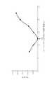
洗浄液の吐出位置におけるガス吐出位置側界面と、ガスの吐出位置における洗浄液吐出位置側界面との距離dをウエハ毎に変更して設定し、その他の条件は評価試験1と同様にして実験を行い、洗浄処理後の各ウエハWの欠陥数(パーティクルの数)を測定した。図24はその結果を示したグラフであり前記界面間の距離dが7.35mm、9.85mm、12.35mm、14.85mm、17.35mm、19.85mm、22.35mmのときに欠陥数は夫々810個、430個、25個、422個、891個、1728個、2162個である。距離dが小さすぎると乾燥領域6が形成されなかったり、乾燥が遅れたりなどの不具合が起こり、また距離dが大きすぎると瞬時に広いエリアで乾燥が起こり、欠陥数が多くなった。欠陥数は実用的には500個以下であることが好ましいので、この実験の結果及び装置の組み立てや加工の誤差を考えると、欠陥数を抑えるために有効な前記距離dの範囲は9mm〜15mmであると言える。(Evaluation Test 3)
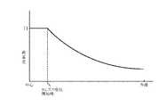
The distance d between the gas discharge position side interface at the cleaning liquid discharge position and the cleaning liquid discharge position side interface at the gas discharge position is set to be changed for each wafer, and the other conditions are the same as in the
(評価試験3)
ガスノズル5からN2ガスを吐出して乾燥領域6を形成した後、洗浄液ノズル4を10mm/秒の等速でウエハの周縁に向けて移動した他は評価試験1と同様にして洗浄を行った。欠陥箇所は303であり、洗浄液ノズル4の移動速度が6.5mm/秒である評価試験1に比べて欠陥箇所が多かった。このことからノズルの移動速度が欠陥数に影響することが示された。(Evaluation Test 3)
After the N2 gas was discharged from the
W ウエハ
2 スピンチャック
23 現像液ノズル
28 ガイドレール
3 カップ体
4 洗浄液ノズル
42 洗浄液供給路
43 洗浄液供給系
44 ノズルアーム
45 移動基体
5 ガスノズル
6 乾燥領域
7 制御部
C ウエハの中心部
R 洗浄液
G N2ガス
Claims (3)
Translated fromJapanese基板を略水平に保持しつつ基板に垂直な軸の周りで回転させる工程と、
洗浄液を吐出する洗浄液ノズルを用いて回転する基板上の中心部に洗浄液を供給して液膜を形成する工程と、
前記洗浄液ノズルから吐出された洗浄液を受ける基板上の位置が前記回転する基板上の中心部から基板上の周縁部に向かって一定距離移動するように前記洗浄液ノズルを移動させる工程と、
前記洗浄液を受ける基板上の位置が基板上の中心部から一定距離離間した状態を保持しつつ、気体を吐出するガスノズルを用いて前記回転する基板上の中心部に所定時間気体を吐出することにより基板上の中心部に乾燥領域を形成する工程と、
基板上の中心部に乾燥領域が形成された後、前記洗浄液を受ける基板上の位置が前記回転する基板上の周縁部に向かって連続的に移動するように10mm/秒を越えない速度で前記洗浄液ノズルを移動させるとともに、前記ガスノズルから吐出された気体を受ける基板上の位置が前記洗浄液を受ける基板上の位置から前記一定距離離間しつつ前記洗浄液を受ける基板上の位置の移動経路をたどるように前記ガスノズルを連続的に移動させる工程と、
を備え、
前記洗浄液ノズル及び前記ガスノズルを連続的に移動させる工程は、前記中心部に気体が吐出されて形成された前記乾燥領域が瞬時に前記洗浄液の吐出される位置まで到達して前記基板上に洗浄液の液膜と乾燥領域との界面を形成し、当該界面が形成された状態で前記洗浄液の吐出位置を前記乾燥領域が基板の外側に広がる速度よりも遅い速度で基板の周縁部に向かって移動させるように、洗浄液ノズルの移動速度、洗浄液の吐出流量及び基板の回転数が制御される工程と、前記洗浄液の各吐出位置における前記基板の回転による遠心力が一定となるように前記基板の回転数を制御する工程と、
を含み、
前記一定距離は、9mm以上15mm以下であり、
前記洗浄液ノズルと共にガスノズルを移動させる工程は、前記洗浄液を受ける基板上の位置が、基板周縁部から2mm〜10mm離れた位置に移動するように行われ、
洗浄液を受ける基板上の位置が前記基板周縁部から離れた位置に移動したときに、基板を回転させながら前記洗浄液の吐出を停止する工程と、
前記洗浄液の吐出停止後に、遠心力により前記基板上の洗浄液を基板から除去するために引き続き基板を回転させる工程と、
を備え、
前記洗浄液を受ける基板上の位置が基板上の中心部から基板上の周縁部に向かって一定距離移動するように前記洗浄液ノズルを移動させる工程は、基板を1500rpm〜2000rpmで回転させながら行うことを特徴とすることを特徴とする基板洗浄方法。A substrate cleaning method for cleaning and drying a water-repellent substrate,
Rotating around an axis perpendicular to the substrate while holding the substrate substantially horizontal;
Supplying a cleaning liquid to a central portion on a rotating substrate using a cleaning liquid nozzle for discharging the cleaning liquid to form a liquid film;
Moving the cleaning liquid nozzle so that a position on the substrate that receives the cleaning liquid discharged from the cleaning liquid nozzle moves from the central part on the rotating substrate toward a peripheral part on the substrate by a certain distance;
By discharging a gas to the central portion on the rotating substrate for a predetermined time using a gas nozzle that discharges the gas while maintaining a state where the position on the substrate that receives the cleaning liquid is separated from the central portion on the substrate by a certain distance. Forming a dry region in the center of the substrate;
After a dry region is formed at the center on the substrate, the position on the substrate that receives the cleaning liquid moves at aspeed not exceeding 10 mm / second so that the position on the substrate continuously moves toward the peripheral edge on the rotating substrate. The cleaning liquid nozzle is moved, and the position on the substrate that receives the gas discharged from the gas nozzle follows the moving path of the position on the substrate that receives the cleaning liquid while being spaced apart from the position on the substrate that receives the cleaning liquid by the predetermined distance. Continuously moving the gas nozzle to
With
In the step of continuously moving the cleaning liquid nozzle and the gas nozzle, the dry region formed by discharging gas to the central portion instantaneously reaches a position where the cleaning liquid is discharged and the cleaning liquid is formed on the substrate. An interface between the liquid film and the dry region is formed, and the cleaning liquid discharge position is moved toward the peripheral edge of the substrate at a speed slower than the speed at which the dry region spreads outside the substrate with the interface formed. As described above, the movement speed of the cleaning liquid nozzle, the discharge flow rate of the cleaning liquid, and the rotation speed of the substrate are controlled, and the rotation speed of the substrate so that the centrifugal force due to the rotation of the substrate at each discharge position of the cleaning liquid is constant. Controlling the process,
Only including,
The certain distance is 9 mm or more and 15 mm or less,
The step of moving the gas nozzle together with the cleaning liquid nozzle is performed such that the position on the substrate that receives the cleaning liquid moves to a position 2 mm to 10 mm away from the peripheral edge of the substrate,
Stopping the discharge of the cleaning liquid while rotating the substrate when the position on the substrate for receiving the cleaning liquid moves to a position away from the peripheral edge of the substrate;
A step of continuously rotating the substrate in order to remove the cleaning solution on the substrate from the substrate by centrifugal force after stopping the discharge of the cleaning solution;
With
The step of moving the cleaning liquid nozzle so that the position on the substrate that receives the cleaning liquid moves a certain distance from the central portion on the substrate toward the peripheral portion on the substrate is performed while rotating the substrate at 1500 rpm to 2000 rpm. A substrate cleaning method characterized by comprising:
前記洗浄液を受ける基板上の位置が基板上の中心部に位置する状態で基板が第1の回転速度で回転し、前記洗浄液を受ける基板上の位置が基板上の周縁部側に位置する状態で基板が前記第1の回転速度より低い第2の回転速度で回転するように基板の回転速度を段階的または連続的に変化させる工程を含むことを特徴とする請求項1記載の基板洗浄方法。The process of rotating the substrate
The substrate rotates at the first rotational speed in a state where the position on the substrate that receives the cleaning liquid is located at the central portion on the substrate, and the position on the substrate that receives the cleaning liquid is positioned on the peripheral edge side. 2. The substrate cleaning method according to claim 1, further comprising a step of changing the rotation speed of the substrate stepwise or continuously so that the substrate rotates at a second rotation speed lower than the first rotation speed.
Priority Applications (1)
| Application Number | Priority Date | Filing Date | Title |
|---|---|---|---|
| JP2014053800AJP5994804B2 (en) | 2014-03-17 | 2014-03-17 | Substrate cleaning method |
Applications Claiming Priority (1)
| Application Number | Priority Date | Filing Date | Title |
|---|---|---|---|
| JP2014053800AJP5994804B2 (en) | 2014-03-17 | 2014-03-17 | Substrate cleaning method |
Related Parent Applications (1)
| Application Number | Title | Priority Date | Filing Date |
|---|---|---|---|
| JP2012088434ADivisionJP5541311B2 (en) | 2012-04-09 | 2012-04-09 | Substrate cleaning method, substrate cleaning apparatus, developing method, developing apparatus, and storage medium |
Publications (2)
| Publication Number | Publication Date |
|---|---|
| JP2014123773A JP2014123773A (en) | 2014-07-03 |
| JP5994804B2true JP5994804B2 (en) | 2016-09-21 |
Family
ID=51403967
Family Applications (1)
| Application Number | Title | Priority Date | Filing Date |
|---|---|---|---|
| JP2014053800AActiveJP5994804B2 (en) | 2014-03-17 | 2014-03-17 | Substrate cleaning method |
Country Status (1)
| Country | Link |
|---|---|
| JP (1) | JP5994804B2 (en) |
Families Citing this family (4)
| Publication number | Priority date | Publication date | Assignee | Title |
|---|---|---|---|---|
| JP6481644B2 (en)* | 2016-03-10 | 2019-03-13 | 東京エレクトロン株式会社 | Substrate processing method, substrate processing apparatus, and storage medium |
| JP6812262B2 (en)* | 2017-02-09 | 2021-01-13 | 株式会社Screenホールディングス | Substrate processing equipment and substrate processing method |
| JP2023045958A (en)* | 2021-09-22 | 2023-04-03 | キオクシア株式会社 | Device and method for processing substrate |
| JP7424424B2 (en)* | 2021-11-02 | 2024-01-30 | 東京エレクトロン株式会社 | Liquid processing equipment |
Family Cites Families (9)
| Publication number | Priority date | Publication date | Assignee | Title |
|---|---|---|---|---|
| JP3013120B2 (en)* | 1991-08-26 | 2000-02-28 | 東京エレクトロン株式会社 | Cleaning and drying equipment |
| KR100292075B1 (en)* | 1998-12-29 | 2001-07-12 | 윤종용 | Wafer processing device for semiconductor device manufacturing |
| JP3322853B2 (en)* | 1999-08-10 | 2002-09-09 | 株式会社プレテック | Substrate drying device and cleaning device, and drying method and cleaning method |
| JP2002015984A (en)* | 2000-04-27 | 2002-01-18 | Toshiba Corp | Film formation method |
| JP4324527B2 (en)* | 2004-09-09 | 2009-09-02 | 東京エレクトロン株式会社 | Substrate cleaning method and developing apparatus |
| JP2006245381A (en)* | 2005-03-04 | 2006-09-14 | Semes Co Ltd | Device and method for washing and drying substrate |
| JP4527660B2 (en)* | 2005-06-23 | 2010-08-18 | 東京エレクトロン株式会社 | Substrate processing method and substrate processing apparatus |
| JP4607755B2 (en)* | 2005-12-19 | 2011-01-05 | 東京エレクトロン株式会社 | Substrate cleaning method, substrate cleaning apparatus, control program, and computer-readable storage medium |
| JP4937678B2 (en)* | 2006-08-29 | 2012-05-23 | 大日本スクリーン製造株式会社 | Substrate processing method and substrate processing apparatus |
- 2014
- 2014-03-17JPJP2014053800Apatent/JP5994804B2/enactiveActive
Also Published As
| Publication number | Publication date |
|---|---|
| JP2014123773A (en) | 2014-07-03 |
Similar Documents
| Publication | Publication Date | Title |
|---|---|---|
| JP5151629B2 (en) | Substrate cleaning method, substrate cleaning apparatus, developing method, developing apparatus, and storage medium | |
| JP4324527B2 (en) | Substrate cleaning method and developing apparatus | |
| US8440266B2 (en) | Developing device, developing method and storage medium | |
| TWI567815B (en) | Substrate cleaning method, substrate cleaning apparatus and storage medium for cleaning substrate | |
| TWI390363B (en) | Developing device, developing method and storage medium | |
| JP4194495B2 (en) | Coating / developing equipment | |
| KR101512642B1 (en) | Developing processing method and developing apparatus | |
| JP4900116B2 (en) | Development method, development device, and storage medium | |
| US20120111373A1 (en) | Substrate cleaning method, substrate cleaning apparatus and storage medium for substrate cleaning | |
| JP5212538B2 (en) | Development method, development device, and storage medium | |
| JP5541311B2 (en) | Substrate cleaning method, substrate cleaning apparatus, developing method, developing apparatus, and storage medium | |
| JP5994804B2 (en) | Substrate cleaning method | |
| JP4684858B2 (en) | Rinse processing method, development processing method, development processing apparatus, control program, and computer-readable storage medium | |
| JP5440642B2 (en) | Substrate cleaning method, substrate cleaning apparatus, developing method, developing apparatus, and storage medium | |
| JP2021072406A (en) | Substrate processing method and substrate processing apparatus | |
| JP5104994B2 (en) | Developing device, developing method, and storage medium | |
| JP6696306B2 (en) | Liquid processing method, liquid processing apparatus, and storage medium | |
| JP2002367899A (en) | Development method | |
| KR102682854B1 (en) | Method and apparatus for treating substrate | |
| JP2004014869A (en) | Developing device | |
| WO2021020215A1 (en) | Development apparatus and development method |
Legal Events
| Date | Code | Title | Description |
|---|---|---|---|
| A521 | Request for written amendment filed | Free format text:JAPANESE INTERMEDIATE CODE: A523 Effective date:20140508 | |
| A977 | Report on retrieval | Free format text:JAPANESE INTERMEDIATE CODE: A971007 Effective date:20150520 | |
| A131 | Notification of reasons for refusal | Free format text:JAPANESE INTERMEDIATE CODE: A131 Effective date:20150602 | |
| A521 | Request for written amendment filed | Free format text:JAPANESE INTERMEDIATE CODE: A523 Effective date:20150730 | |
| A131 | Notification of reasons for refusal | Free format text:JAPANESE INTERMEDIATE CODE: A131 Effective date:20151222 | |
| A521 | Request for written amendment filed | Free format text:JAPANESE INTERMEDIATE CODE: A523 Effective date:20160218 | |
| TRDD | Decision of grant or rejection written | ||
| A01 | Written decision to grant a patent or to grant a registration (utility model) | Free format text:JAPANESE INTERMEDIATE CODE: A01 Effective date:20160726 | |
| A61 | First payment of annual fees (during grant procedure) | Free format text:JAPANESE INTERMEDIATE CODE: A61 Effective date:20160808 | |
| R150 | Certificate of patent or registration of utility model | Ref document number:5994804 Country of ref document:JP Free format text:JAPANESE INTERMEDIATE CODE: R150 | |
| R250 | Receipt of annual fees | Free format text:JAPANESE INTERMEDIATE CODE: R250 | |
| R250 | Receipt of annual fees | Free format text:JAPANESE INTERMEDIATE CODE: R250 | |
| R250 | Receipt of annual fees | Free format text:JAPANESE INTERMEDIATE CODE: R250 | |
| R250 | Receipt of annual fees | Free format text:JAPANESE INTERMEDIATE CODE: R250 | |
| R250 | Receipt of annual fees | Free format text:JAPANESE INTERMEDIATE CODE: R250 | |
| R250 | Receipt of annual fees | Free format text:JAPANESE INTERMEDIATE CODE: R250 | |
| R250 | Receipt of annual fees | Free format text:JAPANESE INTERMEDIATE CODE: R250 |