JP5994780B2 - Impact test method for chemically strengthened glass - Google Patents
Impact test method for chemically strengthened glassDownload PDFInfo
- Publication number
- JP5994780B2 JP5994780B2JP2013526920AJP2013526920AJP5994780B2JP 5994780 B2JP5994780 B2JP 5994780B2JP 2013526920 AJP2013526920 AJP 2013526920AJP 2013526920 AJP2013526920 AJP 2013526920AJP 5994780 B2JP5994780 B2JP 5994780B2
- Authority
- JP
- Japan
- Prior art keywords
- crack
- chemically strengthened
- glass
- strengthened glass
- slow
- Prior art date
- Legal status (The legal status is an assumption and is not a legal conclusion. Google has not performed a legal analysis and makes no representation as to the accuracy of the status listed.)
- Active
Links
Images


Classifications
- G—PHYSICS
- G01—MEASURING; TESTING
- G01N—INVESTIGATING OR ANALYSING MATERIALS BY DETERMINING THEIR CHEMICAL OR PHYSICAL PROPERTIES
- G01N3/00—Investigating strength properties of solid materials by application of mechanical stress
- G01N3/30—Investigating strength properties of solid materials by application of mechanical stress by applying a single impulsive force, e.g. by falling weight
- G01N3/303—Investigating strength properties of solid materials by application of mechanical stress by applying a single impulsive force, e.g. by falling weight generated only by free-falling weight
- G—PHYSICS
- G01—MEASURING; TESTING
- G01M—TESTING STATIC OR DYNAMIC BALANCE OF MACHINES OR STRUCTURES; TESTING OF STRUCTURES OR APPARATUS, NOT OTHERWISE PROVIDED FOR
- G01M7/00—Vibration-testing of structures; Shock-testing of structures
- G01M7/08—Shock-testing
Landscapes
- Physics & Mathematics (AREA)
- General Physics & Mathematics (AREA)
- Health & Medical Sciences (AREA)
- Life Sciences & Earth Sciences (AREA)
- Chemical & Material Sciences (AREA)
- Analytical Chemistry (AREA)
- Biochemistry (AREA)
- General Health & Medical Sciences (AREA)
- Immunology (AREA)
- Pathology (AREA)
- Investigating Strength Of Materials By Application Of Mechanical Stress (AREA)
- Surface Treatment Of Glass (AREA)
Description
Translated fromJapanese本発明は、化学強化により圧縮応力層が形成された化学強化ガラスの衝撃試験方法に関する。The present invention relates toan impact test method forchemically strengthened glass in which a compressive stress layer is formed bychemical strengthening .
近年、携帯電話、携帯情報端末(PDA)等のフラットパネルディスプレイ装置において、ディスプレイの保護ならびに美観を高めるために、画像表示部分よりも広い領域となるように薄い板状のカバーガラスをディスプレイの前面に配置することが行なわれている。このようなフラットパネルディスプレイ装置に対しては、軽量・薄型化が要求されており、そのため、ディスプレイ保護用に使用されるカバーガラスも薄くすることが要求されている。しかし、カバーガラスの厚さを薄くしていくと、強度が低下し、使用中または携帯中の落下などによりカバーガラス自身が割れてしまうことがあり、ディスプレイ装置を保護するという本来の役割を果たすことができなくなるという問題があった。 In recent years, in flat panel display devices such as mobile phones and personal digital assistants (PDAs), a thin plate-like cover glass has been applied to the front surface of the display so as to have a wider area than the image display portion in order to enhance display protection and aesthetics. It has been done to arrange. Such flat panel display devices are required to be lightweight and thin, and accordingly, it is also required to make cover glass used for display protection thinner. However, as the thickness of the cover glass is reduced, the strength decreases, and the cover glass itself may be broken due to falling in use or while carrying it, which plays the original role of protecting the display device. There was a problem that it was impossible.
このため従来のカバーガラスは、ガラス板を化学強化することで表面に圧縮応力層を形成しカバーガラスの耐傷性を高めていた(例えば、特許文献1)。 For this reason, the conventional cover glass formed the compressive-stress layer on the surface by chemically strengthening a glass plate, and raised the scratch resistance of the cover glass (for example, patent document 1).
しかしながら、ユーザーがフラットパネルディスプレイ装置を誤って落下させた場合などカバーガラスに衝撃を与えた際に、化学強化したカバーガラスであっても、圧縮応力層を突き抜ける傷を起点にガラスが比較的遅い速度で割れるスロークラックが生じることがある。(以下、このようなガラスの割れ方をスロークラック割れと呼ぶ。) However, when a user accidentally drops a flat panel display device and gives an impact to the cover glass, even if it is a chemically strengthened cover glass, the glass is relatively slow starting from scratches that penetrate the compressive stress layer. Slow cracks that break at speed may occur. (Hereinafter, this method of breaking the glass is called slow cracking.)
これまで、上記のようなスロークラック割れに対する研究及びスロークラック割れに強いカバーガラスの開発に当たり、スロークラック割れを再現することは非常に難しかった。具体的には、フラットパネルディスプレイ装置を組み立てた後、それらを相当数、地面などに落下させて破壊し、それら割れたガラスを評価して、偶然的にスロークラック割れを起こしたガラスを抽出する必要があった。 Up to now, it has been very difficult to reproduce the slow crack cracks in the research on the above-mentioned slow crack cracks and the development of the cover glass that is resistant to the slow crack cracks. Specifically, after assembling the flat panel display device, a considerable number of them are dropped on the ground and destroyed, the broken glass is evaluated, and the glass that accidentally caused the slow crack crack is extracted. There was a need.
しかしながら、実際の製品であるフラットパネルディスプレイ装置を地面に落下させてスロークラック割れを再現することは、効率が悪いばかりかフラットパネルディスプレイ装置自体を無駄にしてしまうこととなる。従って、フラットパネルディスプレイ装置が製品となる前の段階で、化学強化ガラスにスロークラック割れを再現させることが望まれていた。 However, dropping a flat panel display device, which is an actual product, on the ground to reproduce a slow crack break not only is inefficient, but also wastes the flat panel display device itself. Therefore, it has been desired to reproduce slow cracking in the chemically strengthened glass before the flat panel display device becomes a product.
そこで、本発明は、化学強化ガラスにスロークラック割れを再現させることが可能な化学強化ガラスの衝撃試験方法を提供することを目的とする。Then, an object of this invention is to providethe impact test method ofchemically strengthened glass which can reproduce slow crack cracking inchemically strengthened glass .
本発明者らは、スロークラック割れについて調査、研究を進める上で、スロークラック割れのメカニズムについて解明し、本発明に至った。 The present inventors have elucidated the mechanism of slow crack cracking in researching and researching slow crack cracking, and have reached the present invention.
本発明は、以下の態様を提供するものである。
(1) 表面に圧縮応力層が形成された化学強化ガラスの衝撃試験方法であって、
前記化学強化ガラスを基台上に配置し、前記圧縮応力層の深さ以上の大きさの研磨材を含むサンドペーパーの擦り面に前記化学強化ガラスの一面を接触させた状態で、衝撃物を上方から落下させる化学強化ガラスの衝撃試験方法。
(2) 前記サンドペーパーは、前記化学強化ガラスの上方に配置する(1)に記載の化学強化ガラスの衝撃試験方法。
(3) 前記サンドペーパーの擦り面に接触しない前記化学強化ガラスの他面に、飛散防止フィルムを張る(1)又は(2)に記載の化学強化ガラスの衝撃試験方法。The present invention provides the following aspects.
(1) An impact test method for chemically strengthened glass having a compressive stress layer formed on a surface thereof,
In the state where the chemically strengthened glass is disposed on a base, and one surface of the chemically strengthened glass is brought into contact with a rubbing surface of a sandpaper containing an abrasive having a size larger than the depth of the compressive stress layer, Impact test method for chemically strengthened glass dropped from above.
(2) The impact test method for chemically strengthened glass according to (1), wherein the sandpaper is disposed above the chemically strengthened glass.
(3) The impact test method for chemically strengthened glass according to (1) or (2), wherein a scattering prevention film is stretched on the other surface of the chemically strengthened glass that does not contact the rubbing surface of the sandpaper.
上記(1)に記載の化学強化ガラスの衝撃試験方法によれば、フラットパネルディスプレイ装置で発生するスロークラック割れを再現することができ、これにより、フラットパネルディスプレイ装置自体を実際に落下させなくても、化学強化ガラスのみでスロークラック割れを発生させることができ、新たな硝材の開発などに利用することができる。また、安価で容易に入手することができるサンドペーパーを用いることで、衝撃試験のコストを削減することができる。 According to the impact test method for chemically tempered glass described in (1) above, it is possible to reproduce the slow cracking generated in the flat panel display device, so that the flat panel display device itself does not actually fall. However, it is possible to generate slow cracks only with chemically strengthened glass, which can be used for the development of new glass materials. Moreover, the cost of the impact test can be reduced by using a sandpaper that is inexpensive and easily available.
また、上記(2)に記載の化学強化ガラスの衝撃試験方法によれば、フラットパネルディスプレイ装置が地面に落下した状態に近い状態を作り出すことができ、スロークラック割れの再現性を向上させることができる。 In addition, according to the impact test method for chemically strengthened glass described in (2) above, it is possible to create a state close to the state in which the flat panel display device is dropped on the ground, and to improve the reproducibility of the slow crack cracking. it can.
また、上記(3)に記載の化学強化ガラスの衝撃試験方法によれば、割れた化学強化ガラスの観察が容易となる。 Moreover, according to the impact test method for chemically strengthened glass described in the above (3), it is easy to observe the chemically strengthened glass.
以下、本発明の化学強化ガラスの割れ再現方法について説明するが、先ず、本発明者らの見出した、フラットパネルディスプレイ装置を落下させたときに発生するスロークラック割れのメカニズムについて説明する。
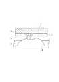
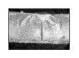
図1はフラットパネルディスプレイ装置が落下した際にカバーガラスにスロークラック割れが発生する状況を示す模式図、図2(a)はスロークラック割れが発生するときの破壊起点を示す模式図、図2(b)は図2(a)の破壊起点から発生したクラックを示す模式図、図3(a)はスロークラック割れが発生したフラットパネルディスプレイ装置の写真を示す図、図3(b)は破壊起点を上方から見た拡大写真を示す図、図3(c)は破壊起点を側方から見た写真を示す図である。Hereinafter, the method for reproducing cracks in chemically tempered glass of the present invention will be described. First, the mechanism of slow cracks that occur when the flat panel display device is dropped, as found by the present inventors, will be described.
FIG. 1 is a schematic diagram showing a situation where a slow crack crack is generated in the cover glass when the flat panel display device is dropped, and FIG. 2A is a schematic diagram showing a fracture starting point when the slow crack crack is generated, FIG. FIG. 3B is a schematic diagram showing a crack generated from the fracture starting point in FIG. 2A, FIG. 3A is a diagram showing a photograph of a flat panel display device in which a slow crack crack has occurred, and FIG. FIG. 3C is a diagram showing an enlarged photograph of the starting point seen from above, and FIG. 3C is a diagram showing a photograph of the fracture starting point seen from the side.
フラットパネルディスプレイ装置は、画像表示部を囲うように略矩形状のフレームが設けられ、カバーガラスがフレーム上に支持されている。図1に示すように、フラットパネルディスプレイ装置が地面(アスファルト・コンクリート)に落下して、カバーガラス2が下に向いた状態でアスファルト・コンクリート3中の小石4上の砂5等に接触すると、破壊起点Oに圧縮応力が作用しその周りに引張応力が作用する(図2(a))。続いて、破壊起点Oには引張応力が作用しクラックCが伸びて、カバーガラス2が割れる(図2(b))。なお、破壊起点は、カバーガラスの中央部に発生することもあるが、フレームによりカバーガラスの撓みが拘束されるため、フレームに支持された領域の一部に発生することが多い。 The flat panel display device is provided with a substantially rectangular frame so as to surround the image display unit, and a cover glass is supported on the frame. As shown in FIG. 1, when the flat panel display device falls on the ground (asphalt / concrete) and the
このときのカバーガラス2の割れは、図3(c)の破断面から明らかなように、圧縮応力層の深さより深い傷が破壊起点となっている。図3(a)及び(b)では、破壊起点から一本のクラックが延びてカバーガラスが2つに割れている。この図3(c)に示す破断面をさらに観察すると、圧縮応力層の深さより深い破壊起点の回りには、鏡のように滑らかな鏡面半径(mirror radius)の長い鏡面(mirror)が見られる。 As is apparent from the fracture surface of FIG. 3C, the crack of the
図4は、図3(c)の破断面を模式的に示す図である。破断面には、破壊の過程、すなわち、破壊起点、破壊の進行方向、破壊が緩やかに進んだか、急速に進んだかなどの要因が反映される。このスロークラック割れの破断面解析によれば、鏡面半径(mirror radius)の長い鏡面は小さな応力により破壊が進行したことを意味しており、このような滑らかな破断面は、クラックがゆっくり音速に比べてずっと遅い速度で成長したことを意味している。従って、図3(c)の破断面によれば、カバーガラスには、圧縮応力層の深さより深い起点が形成された後、クラックがゆっくり成長し、小さな応力で破壊が進行したことが分かる。このようなスロークラック割れにより割れたカバーガラスは、割れ破片が数ピース〜(場合によっては)数十ピースになる。典型的には、2ピースから20ピースであり、図3(a)及び(b)に示す破壊起点から一本のクラックが延びてカバーガラスが2つに割れた例は、スロークラック割れの象徴的な例である。 FIG. 4 is a diagram schematically showing a fracture surface of FIG. The fracture surface reflects factors such as the process of destruction, that is, the origin of the destruction, the direction of the destruction, whether the destruction progressed slowly or rapidly. According to the fracture surface analysis of this slow crack, the mirror surface with a long mirror radius means that the fracture progressed due to a small stress. It means that it grew at a much slower rate. Therefore, according to the fractured surface of FIG. 3 (c), it can be seen that after the starting point deeper than the depth of the compressive stress layer was formed on the cover glass, cracks grew slowly and the fracture proceeded with a small stress. The cover glass broken by such slow cracking has several pieces to several tens of pieces (in some cases). Typically, it is 2 to 20 pieces, and an example in which one crack extends from the fracture starting point shown in FIGS. 3A and 3B and the cover glass breaks into two is a symbol of slow crack cracking. Example.
スロークラック割れであるか否かは、よりミクロには次のようにして判別される。まず、破壊起点がわかるようなものでなければスロークラック割れとはいえない。また、その破壊起点付近を観察して圧縮応力層を突き抜けるような傷すなわち圧縮応力層深さ(いわゆるDOL)よりも深い傷が破壊起点であることが確認された場合はスロークラック割れである。また、鏡面半径が長く、破面断面が鏡面でありミストやハックルが認められない場合はスロークラック割れである。 Whether it is a slow crack or not is determined more microscopically as follows. First, it cannot be said that it is a slow crack unless it can understand the starting point of fracture. In addition, when a crack that penetrates the compressive stress layer, that is, a crack deeper than the compressive stress layer depth (so-called DOL), is observed near the fracture starting point, it is a slow crack crack. Further, when the mirror surface radius is long, the fracture surface section is mirror surface, and no mist or hackles are observed, it is a slow crack crack.
上述したように、スロークラック割れを再現することは非常に難しく、カバーガラスのみを地面に落下させても、偶然にスロークラック割れが発生することがあるとしても再現性が得られない。即ち、スロークラック割れではない割れ方(以下、非スロークラック割れとも呼ぶ。)をする場合が多く発生し、カバーガラスが無駄になってしまう。 As described above, it is very difficult to reproduce the slow crack crack, and even if only the cover glass is dropped on the ground, even if the slow crack crack occurs by chance, the reproducibility cannot be obtained. That is, there are many cases in which cracking is not slow cracking (hereinafter also referred to as non-slow cracking), and the cover glass is wasted.
スロークラック割れと対比する、非スロークラック割れとして、ヌープ圧子をガラス表面に押し込んで生じたカバーガラスの割れについて説明する。図5は、非スロークラック割れによるカバーガラスの破壊起点を側方から見た写真を示す図であり、図6は図5の破断面を模式的に示す図である。 As a non-slow crack crack compared with the slow crack crack, the crack of the cover glass caused by pushing the Knoop indenter into the glass surface will be described. FIG. 5 is a view showing a photograph of a cover glass breakage starting point caused by non-slow crack cracking as viewed from the side, and FIG. 6 is a view schematically showing a broken surface of FIG.
この非スロークラック割れの破断面を観察すると、圧縮応力層内に破壊起点が形成され、回りに鏡のように滑らかな鏡面半径(mirror radius)の短い鏡面(mirror)が見られ、さらに鏡面の回りには、ミスト面(mist)が存在する。この非スロークラック割れの破断面解析によれば、鏡面半径(mirror radius)の短い鏡面は大きな応力により破壊が進行したことを意味し、ミスト面は、クラックが急速に成長したことを意味している。従って、図5の破断面によれば、カバーガラスには、圧縮応力層の深さより浅い破壊起点が形成された後、大きな応力で破壊が進行しクラックが急速に成長したことが分かる。非スロークラック割れが生じると、カバーガラスは後述する図15(e)に示すように、蜘蛛の巣状に延びた複数のクラックにより複数(20枚以上)のガラス片となる(以下、このような割れ方をスパイダー割れとも呼ぶ。)。このように、スロークラック割れと非スロークラック割れとは、全く異なるモードで破壊が生じていることが分かる。 When the fracture surface of this non-slow crack is observed, a fracture starting point is formed in the compressive stress layer, and a mirror with a short mirror radius is seen around the mirror. There is a mist around. According to the fracture surface analysis of this non-slow crack, a mirror surface with a short mirror radius means that the fracture progressed due to a large stress, and the mist surface means that the crack grew rapidly. Yes. Therefore, according to the fractured surface of FIG. 5, it can be seen that after the fracture starting point shallower than the depth of the compressive stress layer was formed in the cover glass, the fracture progressed with a large stress and the crack grew rapidly. When non-slow cracking occurs, the cover glass becomes a plurality (20 or more) of glass pieces due to a plurality of cracks extending in the shape of a spider web, as shown in FIG. This is also called spider cracking.) Thus, it can be seen that the slow crack crack and the non-slow crack crack are broken in completely different modes.
非スロークラック割れについては、破壊起点が圧縮応力層内に発生するため、これを防ぐためには表面圧縮応力を大きくすることや圧縮応力層を深くすることが効果的である。しかし、スロークラック割れについては、破壊起点が圧縮応力層を超えた領域に発生するため(傷の深さは典型的には数十〜数百マイクロメートルで、化学強化による圧縮応力層が数〜数十マイクロメートル)、スロークラック割れに強い機械特性を有するカバーガラスを開発する必要がある。そのため、カバーガラスとして使用される化学強化ガラスにスロークラック割れを再現することが今後の研究開発を進めるために非常に重要である。 With respect to non-slow cracking, since a fracture starting point is generated in the compressive stress layer, it is effective to increase the surface compressive stress or deepen the compressive stress layer in order to prevent this. However, with regard to slow cracking, since the fracture starting point occurs in a region beyond the compressive stress layer (the depth of the scratch is typically several tens to several hundreds of micrometers, the compressive stress layer due to chemical strengthening is several It is necessary to develop a cover glass having mechanical properties that are resistant to slow cracking (several tens of micrometers). Therefore, reproducing slow cracks in chemically strengthened glass used as a cover glass is very important for further research and development.
そこで、本発明者らは、このスロークラック割れを再現するための方法を見出した。なお、スロークラック割れとは、上述したように、圧縮応力層の深さより深い破壊起点が形成されて割れが発生したものであり、典型的には、割れ破片が2ピースから20ピースである。逆に言うと、圧縮応力層内の起点から発生した非スロークラック割れは、粉々なガラス片となるので全く異なるモードである。 Therefore, the present inventors have found a method for reproducing this slow crack crack. In addition, as described above, the slow crack crack is a crack generated by forming a fracture starting point deeper than the depth of the compressive stress layer. Typically, the crack fragment is 2 pieces to 20 pieces. Conversely, the non-slow cracking generated from the starting point in the compressive stress layer is a completely different mode because it becomes a shattered glass piece.
<第1実施形態>
第1実施形態のスロークラック割れの再現方法は、図7に示すように、表面に圧縮応力層が形成された化学強化ガラス10を基台11上に配置し、圧縮応力層の深さ以上の大きさの研磨材を含むサンドペーパー12の擦り面12aに化学強化ガラス10を接触させ、鉄球等の球体13を上方から落下させるものである。このとき、サンドペーパー12は、好ましくは化学強化ガラス10の上方に配置され、化学強化ガラス10の上面10aがサンドペーパー12の擦り面12aと接触しており、球体13がサンドペーパー12の擦り面12aとは反対側の面12bに落下する。<First Embodiment>
As shown in FIG. 7, the method for reproducing slow crack cracks according to the first embodiment includes a chemically strengthened
基台11としては、花崗岩のような硬い石から形成されることが好ましい。これにより、破壊起点となる傷が発生しやすいフレームに支持されたカバーガラスの領域と同じように、応力の逃げ場を排除することができる。ただし、基台11の材質は弾性率やたわみを目的にあわせて変更することができ、ストレート材、ガラス、中央がくりぬかれたフレーム等、適宜選択することができる。 The
本発明におけるサンドペーパーは研磨紙(紙やすり、JIS R6252:2006)に限られず基材に研磨材が接着剤によって塗装されたもの、あるいはそれに相当するものを含み、たとえば研磨布(JIS R6251:2006)、耐水研磨紙(JIS R6253:2006)などを含む。 The sandpaper in the present invention is not limited to abrasive paper (sandpaper, JIS R6252: 2006), but includes a substrate coated with an abrasive with an adhesive, or equivalent, such as abrasive cloth (JIS R6251: 2006). ), Water resistant abrasive paper (JIS R6253: 2006) and the like.
サンドペーパー12には、含まれる研磨材の粒度に応じてP12〜P2500番が存在する(JIS R6252、2006)。研磨材は、典型的には、アルミナ、炭化ケイ素である。アスファルト・コンクリートに含まれる砂の粒径を0.06mm〜1mmと想定すると、サンドペーパー12に含まれる研磨材の粒度としてP30〜P600が概ねこれと対応する。 The
JIS R6010、2006によれば例えば、微粉であるP30の研磨材の粒度分布は、1段網上量Q1(1段ふるいの目開き=1.18mm)は0%、1+2段累積網上量Q2(2段ふるいの目開き=850μm)は1%以下、1+2+3段累積網上量Q3(3段ふるいの目開き=710μm)は14±4%、1+2+3+4段累積網上量Q4(4段ふるいの目開き=600μm)は61±9%、1+2+3+4+5段累積網上量Q5(5段ふるいの目開き=500μm)は92%以上、5段ふるいの網下量ΔQは8%以下であり、粗粒であるP600の研磨材の粒度分布は、最大粒子径ds−0は72μm以下、累積沈降高さ3%の粒子径ds−3は43.0μm以下、累積沈降高さ50%の粒子径ds−50は25.8±1.0μm、累積沈降高さ95%の粒子径ds−95は18.0μm以上である。According to JIS R6010, 2006, for example, the particle size distribution of the P30 abrasive that is fine powder is 0% on the 1st stage mesh amount Q1 (1 stage sieve opening = 1.18 mm), 1 + 2 stage cumulative net amount. Q2 (2 stage sieve opening = 850 μm) is 1% or less, 1 + 2 + 3 stage accumulated net amount Q3 (3 stage sieve opening = 710 μm) is 14 ± 4%, 1 + 2 + 3 + 4 stage accumulated net quantity Q4 ( 4-stage sieve opening = 600 μm) is 61 ± 9%, 1 + 2 + 3 + 4 + 5-stage cumulative mesh amount Q5 (5-stage sieve opening = 500 μm) is 92% or more, and mesh quantity ΔQ for 5-stage sieve is 8% or less. , and the particle size distribution of the abrasive is coarse P600, the maximum particle sized s -0 is 72μm or less, the cumulative precipitation height of 3% particle diameterd s -3 is 43.0μm or less, the cumulative precipitation height 50% of the particle diameterd s -50 is 25.8 ± 1.0 micron , Particle sized s -95 95% cumulative sedimentation height is not less than 18.0.
本発明における研磨材の大きさは、サンドペーパーがJIS R6252、2006に準拠しているものである場合には、P12〜P220の粗粒についてはJIS R6010、2006の表2で規定される3段ふるいの目開きD3、P240〜P2500の微粉についてはJIS R6010、2006の表3で規定される累積沈降高さ3%の粒子径上限値d3であり、サンドペーパーがJIS R6252、2006に準拠しているものといえない場合には最大粒径である。When the sandpaper is compliant with JIS R6252, 2006, the size of the abrasive in the present invention is three levels defined in Table 2 of JIS R6010, 2006 for coarse grains of P12 to P220. For fine particles of sieve openings D3 and P240 to P2500, the particle size upper limit d3 is 3% of the cumulative sedimentation height defined in Table 3 of JIS R6010, 2006, and the sandpaper conforms to JIS R6252, 2006. When it cannot be said that it is, it is the maximum particle size.
例えば圧縮応力層の深さを30μmと想定すると、圧縮応力層の深さよりも大きい研磨材を含むサンドペーパーとしては、P30(D3:710μm)、P100(D3:180μm)、P320(d3:66.8μm)、P600(d3:43.0μm)などのサンドペーパーが選択される。For example, assuming that the depth of the compressive stress layer is 30 μm, P30 (D3 : 710 μm), P100 (D3 : 180 μm), P320 (d3 ) are used as sandpaper containing an abrasive larger than the depth of the compressive stress layer. : 66.8 μm), P600 (d3 : 43.0 μm) and the like are selected.
サンドペーパーはその研磨材の大きさが圧縮応力層の深さよりも大きいものとされるが、典型的には研磨材の4段ふるいの目開きD4、累積沈降高さ50%の粒子径ds−50または平均粒子径が圧縮応力層の深さよりも大きいものとされる。The size of the abrasive of the sandpaper is larger than the depth of the compressive stress layer. Typically, the four-stage sieve opening D4 of the abrasive is used, and the particle size d has a cumulative sedimentation height of 50%.s- 50 or an average particle diameter shall be larger than the depth of a compressive-stress layer.
球体13の材質や重量は目的にあわせて変更可能であるが、典型的には、SUS製の4〜150gのステンレス球が用いられる。 The material and weight of the
このように基台11上に配置された化学強化ガラス10に、球体13を落下させることで、化学強化ガラス10にはサンドペーパー12に含まれる研磨材により、上面10a側の圧縮応力層より深いところに破壊起点Oが発生する。 In this way, by dropping the
このとき、破壊起点Oに圧縮応力が作用しその周りに引張応力が作用する(図8(a))。続いて、破壊起点Oには引張応力が作用しクラックCが伸びて、カバーガラスが割れる(図8(b))。即ち、破壊起点の面が上面と下面の違いはあるが、図2(a)及び(b)で説明したスロークラック割れと同じメカニズムで割れが発生する。 At this time, a compressive stress acts on the fracture starting point O, and a tensile stress acts around it (FIG. 8A). Subsequently, a tensile stress acts on the fracture starting point O, the crack C is elongated, and the cover glass is broken (FIG. 8B). That is, although there is a difference between the top surface and the bottom surface of the fracture starting point, cracking occurs by the same mechanism as the slow cracking described in FIGS. 2 (a) and 2 (b).
図13(a)は、P30のサンドペーパー12を化学強化ガラス10の上方に配置し、28g、Φ0.75インチの鉄球13を高さ50mmから落下させてスロークラック割れが発生したカバーガラスの写真を示す図であり、図14は破壊起点を側方から見た写真を示す図である。
化学強化ガラスは3枚に割れているが、図14は図3(c)と同様の破断面を示しており、スロークラック割れと同じメカニズムで割れが発生していることが分かる。FIG. 13A shows a cover glass in which a
Although the chemically strengthened glass is broken into three pieces, FIG. 14 shows a fracture surface similar to that of FIG. 3 (c), and it can be seen that the crack is generated by the same mechanism as the slow crack crack.
このように、落球毎に、化学強化ガラスを目視観察し、化学強化ガラスにクラックが発生しているか、割れていないか等、観察する。サンプル同士を球体の落球高さを変えて衝撃試験する場合、典型的には10〜20回程度測定を繰り返してワイブルプロットをとり、最大・最小・平均割れ高さやワイブルプロットの傾きなどから化学強化ガラスを評価することができる。必要に応じて、化学強化ガラスの全体の割れ方や破壊起点の表面・断面を光学顕微鏡、レーザー顕微鏡等を用いて観察・撮影し、割れモードを分類する。 Thus, for each falling ball, the chemically strengthened glass is visually observed to observe whether the chemically strengthened glass is cracked or not cracked. When impact tests are performed on samples with different falling ball heights, typically the measurement is repeated 10 to 20 times to obtain a Weibull plot, and chemical strengthening is performed based on the maximum / minimum / average crack height and the slope of the Weibull plot. Glass can be evaluated. If necessary, the cracking mode is classified by observing / photographing the entire cracking of the chemically strengthened glass and the surface / cross section of the fracture starting point using an optical microscope, a laser microscope, or the like.
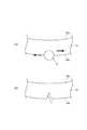
図9は、第1実施形態の変形例を示すものである。
本変形では、図9に示すように、圧縮応力層の深さ以上の大きさの研磨材を含むサンドペーパー12が、化学強化ガラス10の下方に配置され、化学強化ガラス10の下面10bがサンドペーパー12の擦り面12aと接触しており、球体13を化学強化ガラス10の上面10aに落下させるものである。FIG. 9 shows a modification of the first embodiment.
In this modification, as shown in FIG. 9, a
このように配置された化学強化ガラス10に、球体13を落下させることで、化学強化ガラス10にはサンドペーパー12に含まれる研磨材により、下面10b側の圧縮応力層より深いところに破壊起点Oが発生する。 By dropping the
このとき、破壊起点Oに引張応力が作用し(図10(a))、そのままクラックCが伸びて、化学強化ガラス10が割れる(図10(b))。従って、この方法は、圧縮応力層の深さより深い起点が形成されて割れが発生したものである点で、第1実施形態と同じであるが、球体13を落下時に破壊起点Oに引張応力が作用する点では相違している。 At this time, a tensile stress acts on the fracture starting point O (FIG. 10A), the crack C extends as it is, and the chemically strengthened
図15(b)は、P30のサンドペーパー12を化学強化ガラス10の下方に配置し、28g、Φ0.75インチの球体13を高さ25mmから落下させてスロークラック割れが発生したカバーガラスの写真を示す図であり、図16は破壊起点を側方から見た写真を示す図である。
化学強化ガラスは6枚に割れているが、図16は図3(c)と同様の破断面を示しており、スロークラック割れと同じメカニズムで割れが発生していることが分かる。FIG. 15B is a photograph of a cover glass in which a
Although the chemically strengthened glass is broken into six pieces, FIG. 16 shows a fracture surface similar to that in FIG. 3C, and it can be seen that the crack is generated by the same mechanism as the slow crack crack.
<第2実施形態>
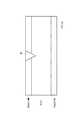
第2実施形態のスロークラック割れの再現方法は、図11に示すように、表面に圧縮応力層が形成された化学強化ガラス10に、圧縮応力層の深さ以上の長さの先細状の先端部21を有し、化学強化ガラス10より硬度の高い衝撃物22を化学強化ガラス10に衝突させるものである。Second Embodiment
As shown in FIG. 11, the method of reproducing the slow crack in the second embodiment is a tapered tip having a length equal to or greater than the depth of the compressive stress layer on the chemically strengthened
本実施形態では、化学強化ガラス10を左右に配置された断面略L字状の支持部材23L、23Rで垂直に支持し、ミサイル形状の先端部21を有する超硬材からなる衝撃物22を振り子状に作動させている。このように配置された化学強化ガラス10に、衝撃物22を衝突させることで、化学強化ガラス10には衝突面の圧縮応力層より深いところに破壊起点が発生する。 In this embodiment, the chemically strengthened
このとき、破壊起点に圧縮応力が作用しその周りに引張応力が作用し、続いて破壊起点には引張応力が作用しクラックが伸びて、カバーガラスが割れ、図2(a)及び(b)で説明したスロークラック割れと同じメカニズムで割れが発生する。なお、本実施形態は、化学強化ガラスに、圧縮応力層の深さ以上の長さ先細状の先端部を有し、化学強化ガラスより硬度の高い衝撃物を化学強化ガラスに衝突させて、圧縮応力層より深いところに破壊起点を発生させることが可能な限り、いかなる構成をも採用することができる。 At this time, a compressive stress acts on the fracture starting point, and a tensile stress acts on the periphery of the fracture starting point. Subsequently, the tensile stress acts on the fracture starting point, the crack extends, and the cover glass breaks. FIGS. 2 (a) and 2 (b) Cracks are generated by the same mechanism as the slow crack cracks described in. In the present embodiment, the chemically tempered glass has a tapered tip that is longer than the depth of the compressive stress layer, and impact material having a hardness higher than that of the chemically tempered glass collides with the chemically tempered glass to compress it. Any configuration can be adopted as long as the fracture starting point can be generated deeper than the stress layer.
また、これら第1及び第2実施形態では、破壊起点Oが形成される面とは反対側の面(図7では化学強化ガラス10の下面10b、図9では化学強化ガラス10の上面10a、図11では衝撃物22が衝突する面と反対側の面)に割れたガラスの飛散を防止のための飛散防止フィルムを張ることで、割れた化学強化ガラスの破断面の観察が容易となる。なお、飛散防止の必要がない場合には、必ずしも飛散防止フィルムを張る必要はない。 Moreover, in these 1st and 2nd embodiment, the surface on the opposite side to the surface where the fracture origin O is formed (in FIG. 7, the
本発明の化学強化ガラスは、例えば435℃の硝酸カリウム(KNO3)溶融塩に4時間浸漬させることで化学強化が行われる。圧縮応力層の深さは、15μm以上であることが好ましく、30μm以上であることがより好ましい。また、化学強化ガラスの圧縮応力は、600MPa以上が好ましく、700MPa以上がより好ましい。The chemically strengthened glass of the present invention is chemically strengthened by immersing it in, for example, a potassium nitrate (KNO3 ) molten salt at 435 ° C. for 4 hours. The depth of the compressive stress layer is preferably 15 μm or more, and more preferably 30 μm or more. Moreover, 600 MPa or more is preferable and, as for the compressive stress of chemically strengthened glass, 700 MPa or more is more preferable.
化学強化ガラスは、板厚が1.5mm以下、より好ましくは、0.3〜1.1mmである。また、例えば以下の組成のガラスが使用される。
(i)モル%で表示した組成で、SiO2を50〜80%、Al2O3を2〜25%、Li2Oを0〜10%、Na2Oを0〜18%、K2Oを0〜10%、MgOを0〜15%、CaOを0〜5%およびZrO2を0〜5%を含むガラス。ここで、例えば「K2Oを0〜10%含む」とはK2Oは必須ではないが10%までの範囲で、かつ、本発明の目的を損なわない範囲で含んでもよい、の意である(以下、同様)。
(ii)モル%で表示した組成が、SiO2を50〜74%、Al2O3を1〜10%、Na2Oを6〜14%、K2Oを3〜11%、MgOを2〜15%、CaOを0〜6%およびZrO2を0〜5%含有し、SiO2およびAl2O3の含有量の合計が75%以下、Na2OおよびK2Oの含有量の合計が12〜25%、MgOおよびCaOの含有量の合計が7〜15%であるガラス。
(iii)モル%で表示した組成が、SiO2を68〜80%、Al2O3を4〜10%、Na2Oを5〜15%、K2Oを0〜1%、MgOを4〜15%およびZrO2を0〜1%含有するガラス。
(iv)モル%で表示した組成が、SiO2を67〜75%、Al2O3を0〜4%、Na2Oを7〜15%、K2Oを1〜9%、MgOを6〜14%およびZrO2を0〜1.5%含有し、SiO2およびAl2O3の含有量の合計が71〜75%、Na2OおよびK2Oの含有量の合計が12〜20%であり、CaOを含有する場合その含有量が1%未満であるガラス。The chemically tempered glass has a plate thickness of 1.5 mm or less, more preferably 0.3 to 1.1 mm. Further, for example, glass having the following composition is used.
(I) 50% to 80% of SiO2 ,2 to 25% of Al2 O3 , 0 to 10% of Li2 O, 0 to 18% of Na2 O, K2 O with a composition expressed in
(Ii) The composition expressed in mol% is SiO2 50-74%, Al2 O3 1-10%, Na2 O 6-14%, K2 O 3-11%,
(Iii) The composition expressed in mol% is SiO2 68-80%, Al2 O3 4-10%, Na2 O 5-15%, K2 O 0-1%, MgO 4 15% and
Composition viewed in (iv) mol%, a SiO2 67 to 75%, theAl 2 O 3 0~4%, 7~15 % of Na2 O, 1 to 9% ofK 2 O,
以下、本発明の実施例について説明する。
厚さ0.7mm、サイズ:50mm×50mmの化学強化用ガラスをフロート法で製造し、435℃の硝酸カリウム(KNO3)溶融塩に4時間浸漬させることで化学強化を行った。化学強化後の表面圧縮応力は約800MPaであり、圧縮応力層の深さは約45μmであった。化学強化された化学強化ガラスは、表面に傷がつかないように、また、表面が他のものに接触しないようにカセットにて搬送し、破壊起点となる面とは反対側の面に飛散防止フィルムを張った。Examples of the present invention will be described below.
A glass for chemical strengthening having a thickness of 0.7 mm and a size: 50 mm × 50 mm was manufactured by a float process, and chemical strengthening was performed by immersing in a molten salt of potassium nitrate (KNO3 ) at 435 ° C. for 4 hours. The surface compressive stress after chemical strengthening was about 800 MPa, and the depth of the compressive stress layer was about 45 μm. Chemically tempered chemically tempered glass is transported in a cassette so that the surface is not scratched and the surface is not in contact with other objects, preventing scattering on the surface opposite to the surface that is the starting point of destruction. I stretched the film.
この化学強化ガラスを第1実施形態の方法、より具体的には、化学強化ガラスの上面がサンドペーパーの擦り面と接触するようにサンドペーパー(シートペーパーと呼ばれる研磨布)を化学強化ガラスの上方に配置し、Φ0.75インチ、28gのSUS製の球体をサンドペーパーの擦り面とは反対側の面に落下させた。また、サンドペーパーとして、P30(D3:710μm)を用い、実施例1〜3で、球体の落下高さを50mmとしたものを実施例1とし、球体の落下高さを100mmとしたものを実施例2とし、球体の落下高さを150mmとしたものを実施例3とし、球体の落下高さを変えながら、化学強化ガラスの破断面及び割れ方を観察した。図12(a)はP30のサンドペーパーの拡大写真であり、図12(b)は、アスファルト・コンクリート(横浜にて採取)の拡大写真であり、図12(c)は、P30のサンドペーパー先端の角度分布と砂の先端の角度分布を示すグラフである。図12(c)は、それぞれサンドペーパーを144箇所、砂を149箇所観測し、サンドペーパー又は砂の先端角度を横軸に、頻度を縦軸に示したものである。P30のサンドペーパーに含まれる研磨材としてのアルミナと、アスファルト・コンクリートに含まれる小石等の形状の近似性から、実施例1〜3では圧縮応力層の深さ以上の大きさの研磨材を含むサンドペーパーのうち、P30のサンドペーパーが選択された。The chemically tempered glass is placed over the chemically tempered glass by the method of the first embodiment, more specifically, the sandpaper (abrasive cloth called sheet paper) is placed above the chemically tempered glass so that the upper surface of the chemically tempered glass is in contact with the rubbing surface of the sandpaper. And a SUS sphere having a diameter of 0.75 inch and 28 g was dropped on the surface opposite to the rubbing surface of the sandpaper. Further, as the sandpaper,P30: using (
結果を図13及び図14に示す。
図13(a)〜(c)から実施例1〜3のいずれにおいても、ガラス片が20枚以下であった。また、図14に示す破断面を観察すると、圧縮応力層の深さより深い傷を破壊起点として、破壊起点の回りには鏡のように滑らかな鏡面半径の長い鏡面が見られた。これにより、実施例1〜3で、スロークラック割れを再現できた。また、実施例1〜3を比べると、球体の落球高さが低くなるほど、割れたガラス片の数が減少する結果となった。The results are shown in FIGS.
In any of Examples 1 to 3 from FIGS. 13A to 13C, the number of glass pieces was 20 or less. Further, when the fracture surface shown in FIG. 14 was observed, a smooth mirror surface having a long mirror radius like a mirror was seen around the fracture starting point with a scratch deeper than the depth of the compressive stress layer as the fracture starting point. Thereby, the slow crack crack was able to be reproduced in Examples 1-3. Moreover, when Examples 1-3 were compared, it resulted in the number of the broken glass pieces decreasing, so that the falling ball height of a sphere became low.
続いて、上記化学強化ガラスと同じ化学強化ガラスを第1実施形態の変形例の方法、より具体的には、化学強化ガラスの下面がサンドペーパーの擦り面と接触するようにサンドペーパーを化学強化ガラスの下方に配置し、Φ0.75インチ、28gのSUS製の球体を化学強化ガラスの上面に落下させた。サンドペーパーのメッシュと球体の落下高さを表1のように変えながら化学強化ガラスの破断面及び割れ方を観察した。
結果を図15及び図16に示す。
図15(a)〜(d)から実施例4〜7のいずれにおいても、ガラス片が20枚以下であった。また、図16に示す破断面を観察すると、圧縮応力層の深さより深い破壊起点が形成され、破壊起点の回りには、滑らかな破断面が存在し、さらにその回りに鏡のように滑らかな鏡面半径の長い鏡面が見られた。これにより、実施例4〜7で、スロークラック割れを再現できた。また、実施例4と実施例5、実施例6と実施例7をそれぞれ比べると、球体の落球高さが低くなるほど、割れたガラス片の数が減少する結果となった。さらに、実施例4と実施例6、実施例5と実施例7をそれぞれ比べると、メッシュが小さくなるほど、即ち粒径が大きくなるほど、割れたガラス片の数が減少する結果となった。The results are shown in FIGS.
In any of Examples 4 to 7 from FIGS. 15A to 15D, the number of glass pieces was 20 or less. Further, when the fracture surface shown in FIG. 16 is observed, a fracture starting point deeper than the depth of the compressive stress layer is formed, and there is a smooth fracture surface around the fracture starting point. A mirror surface with a long mirror radius was observed. Thereby, the slow crack crack was able to be reproduced in Examples 4-7. Moreover, when Example 4 and Example 5, Example 6 and Example 7 were compared, respectively, the result was that the number of broken glass pieces decreased as the falling ball height of the sphere decreased. Furthermore, when Example 4 and Example 6 and Example 5 and Example 7 were compared, respectively, the smaller the mesh, that is, the larger the particle size, the smaller the number of broken glass pieces.
これに対し比較例1では、図15(e)に示すように、ガラス片が20枚以上であり、破断面を観察することはできなかった。これは、P600のサンドペーパーでは、サンドペーパーに含まれる研磨材の大きさが粒径43μm以下であり、さらにサンドペーパーの表面から突出する研磨材の長さはそれよりもさらに短いため、圧縮応力層内に破壊起点が形成されたためと考えられる。従って、比較例1は非スロークラック割れ(スパイダー割れ)と考えられる。 In contrast, in Comparative Example 1, as shown in FIG. 15 (e), the number of glass pieces was 20 or more, and the fractured surface could not be observed. This is because, in the P600 sandpaper, the size of the abrasive contained in the sandpaper is 43 μm or less, and the length of the abrasive protruding from the surface of the sandpaper is even shorter than that. This is thought to be due to the formation of a fracture origin in the layer. Therefore, Comparative Example 1 is considered as non-slow crack cracking (spider cracking).
さらに、上記化学強化ガラスと同じ化学強化ガラスを第1実施形態の変形例の方法で、サンドペーパーのメッシュと、球体の落下高さと、球体の重さを変えながらSUS製の球体を化学強化ガラスの上面に落下させた。球体の落下高さは、30cm、60cm、90cmの3段階とし、球体は4g、9g、17g、29gの4種類の重さの球体を用いた。 Further, the same chemically strengthened glass as the above-mentioned chemically strengthened glass is changed to the chemically strengthened glass by changing the sandpaper mesh, the drop height of the sphere, and the weight of the sphere by the method of the first embodiment. It was dropped on the top surface. The drop height of the sphere was made into three stages of 30 cm, 60 cm, and 90 cm, and the spheres were used in four types of weights of 4 g, 9 g, 17 g, and 29 g.
図17は、P30(D3:710μm)のサンドペーパーを用いたスロークラック割れの再現方法における割れた化学強化ガラスの写真であり、図18は、P100(D3:180μm)のサンドペーパーを用いたスロークラック割れの再現方法における割れた化学強化ガラスの写真である。FIG. 17 is a photograph of broken chemically strengthened glass in a method for reproducing slow cracking using a P30 (D3 : 710 μm) sandpaper, and FIG. 18 uses a P100 (D3 : 180 μm) sandpaper. It is the photograph of the chemically strengthened glass which broke in the reproduction method of the slow crack which had been.
図中、「スロークラック割れ」は、破断面解析からスロークラック割れと判別できたものを意味し、「スパイダー」は、破断面解析から非スロークラック割れ(スパイダー割れ)と判別できたものを意味しており、特に表記がないものについてはいずれか判別できなかったものを示している。「破壊せず」は、ガラスに割れが発生しなかったことを示している。 In the figure, “slow crack cracking” means that the crack surface can be determined as a slow crack crack from the fracture surface analysis, and “spider” means that it can be determined as a non-slow crack crack (spider crack) from the fracture surface analysis. In the case where there is no particular notation, one that cannot be identified is shown. “No breakage” indicates that no breakage occurred in the glass.
図17及び図18より、落球高さが高くなるに従いスロークラック割れよりも非スロークラック割れ(スパイダー割れ)が発生する可能性が高く、球体の重さが重くなるに従いスロークラック割れよりも非スロークラック割れ(スパイダー割れ)が発生する可能性が高いことが分かる。また、P100(D3:180μm)のサンドペーパーを用いた場合には、落球高さが低く及び/又は球体の重さが軽い場合には、割れが発生しなかった。17 and 18, it is more likely that non-slow crack cracking (spider cracking) occurs than slow crack cracking as the falling ball height increases, and non-slow cracking rather than slow crack cracking as the weight of the sphere increases. It can be seen that cracking (spider cracking) is likely to occur. Moreover,P100: in the case of using the (
以上の結果から、上記したようなスロークラック割れの再現方法によりフラットパネルディスプレイ装置自体を実際に落下させなくても、化学強化ガラスのみでスロークラック割れを発生させることができた。これにより、スロークラック割れに強い新たな硝材の開発などに利用することができる。また、安価で容易に入手することができるサンドペーパーを用いることで、検査コストを削減することができる。 From the above results, it was possible to generate slow cracks only with chemically strengthened glass without actually dropping the flat panel display device itself by the method for reproducing slow cracks as described above. Thereby, it can utilize for development of the new glass material strong against a slow crack crack. In addition, the inspection cost can be reduced by using sandpaper that is inexpensive and easily available.
さらに、化学強化ガラスの製造方法として、製造ライン中に、上記方法を取り入れて、球体の落球高さを変えながら球体を化学強化ガラスに落下させることにより閾値を決定し、閾値を基準に化学強化ガラスの品質を判定する抜き取り検査を行うことで、カバーガラスの耐スロークラック割れ性能を管理することができる。 Furthermore, as a method of manufacturing chemically strengthened glass, the above method is incorporated into the production line, the threshold is determined by dropping the sphere onto the chemically strengthened glass while changing the height of the falling ball, and chemical strengthening is performed based on the threshold. By performing a sampling inspection to determine the quality of the glass, the slow cracking resistance of the cover glass can be managed.
なお、本発明は上述した実施形態に何ら限定されるものではなく、その要旨を逸脱しない範囲において種々の形態で実施し得るものである。 The present invention is not limited to the embodiment described above, and can be implemented in various forms without departing from the gist of the present invention.
本出願は、2011年8月4日出願の日本特許出願2011−171197に基づくものであり、その内容はここに参照として取り込まれる。 This application is based on the JP Patent application 2011-171197 of an application on August 4, 2011, The content is taken in here as a reference.
2 カバーガラス
3 アスファルト・コンクリート
4 小石
5 砂
10 化学強化ガラス
10a 上面
11 基台
12 サンドペーパー
12a 擦り面
13 球体
O 破壊起点
C クラック2
Claims (3)
Translated fromJapanese前記化学強化ガラスを基台上に配置し、前記圧縮応力層の深さ以上の大きさの研磨材を含むサンドペーパーの擦り面に前記化学強化ガラスの一面を接触させた状態で、衝撃物を上方から落下させる化学強化ガラスの衝撃試験方法。An impact test method for chemically strengthened glass having a compressive stress layer formed on the surface,
In the state where the chemically strengthened glass is disposed on a base, and one surface of the chemically strengthened glass is brought into contact with a rubbing surface of a sandpaper containing an abrasive having a size larger than the depth of the compressive stress layer, Impact test method for chemically strengthened glass dropped from above.
Applications Claiming Priority (3)
| Application Number | Priority Date | Filing Date | Title |
|---|---|---|---|
| JP2011171197 | 2011-08-04 | ||
| JP2011171197 | 2011-08-04 | ||
| PCT/JP2012/069369WO2013018774A1 (en) | 2011-08-04 | 2012-07-30 | Method for impact-testing chemically strengthened glass, method for reproducing cracks in chemically strengthened glass, and method for manufacturing chemically strengthened glass |
Publications (2)
| Publication Number | Publication Date |
|---|---|
| JPWO2013018774A1 JPWO2013018774A1 (en) | 2015-03-05 |
| JP5994780B2true JP5994780B2 (en) | 2016-09-21 |
Family
ID=47629296
Family Applications (1)
| Application Number | Title | Priority Date | Filing Date |
|---|---|---|---|
| JP2013526920AActiveJP5994780B2 (en) | 2011-08-04 | 2012-07-30 | Impact test method for chemically strengthened glass |
Country Status (6)
| Country | Link |
|---|---|
| US (1) | US9470614B2 (en) |
| JP (1) | JP5994780B2 (en) |
| KR (1) | KR101935076B1 (en) |
| CN (1) | CN103782152B (en) |
| TW (1) | TWI580961B (en) |
| WO (1) | WO2013018774A1 (en) |
Families Citing this family (26)
| Publication number | Priority date | Publication date | Assignee | Title |
|---|---|---|---|---|
| US9359251B2 (en) | 2012-02-29 | 2016-06-07 | Corning Incorporated | Ion exchanged glasses via non-error function compressive stress profiles |
| US11079309B2 (en) | 2013-07-26 | 2021-08-03 | Corning Incorporated | Strengthened glass articles having improved survivability |
| US9517968B2 (en) | 2014-02-24 | 2016-12-13 | Corning Incorporated | Strengthened glass with deep depth of compression |
| TWI773291B (en) | 2014-06-19 | 2022-08-01 | 美商康寧公司 | Glasses having non-frangible stress profiles |
| CN104198309B (en)* | 2014-09-22 | 2016-09-28 | 中国建筑科学研究院 | A test method for wind pressure resistance performance of film-coated glass |
| DE202015009904U1 (en) | 2014-10-08 | 2021-05-14 | Corning Incorporated | Glass-based item |
| US10150698B2 (en) | 2014-10-31 | 2018-12-11 | Corning Incorporated | Strengthened glass with ultra deep depth of compression |
| CN115536270A (en) | 2014-11-04 | 2022-12-30 | 康宁股份有限公司 | Deep non-fragile stress curve and method of making the same |
| US11613103B2 (en) | 2015-07-21 | 2023-03-28 | Corning Incorporated | Glass articles exhibiting improved fracture performance |
| US9701569B2 (en) | 2015-07-21 | 2017-07-11 | Corning Incorporated | Glass articles exhibiting improved fracture performance |
| CN108351284B (en) | 2015-10-30 | 2021-10-15 | 康宁股份有限公司 | Apparatus and method for impact testing of materials |
| US10955311B2 (en)* | 2015-11-18 | 2021-03-23 | Corning Incorporated | Apparatus and methods to determine stresses in cover glass of handheld devices |
| KR102029948B1 (en) | 2015-12-11 | 2019-10-08 | 코닝 인코포레이티드 | Fusion-Formable Glass-Based Products Including Metal Oxide Concentration Gradients |
| JP2017149628A (en)* | 2016-02-26 | 2017-08-31 | 旭硝子株式会社 | Chemically strengthened glass and method for producing chemically strengthened glass |
| KR20210122313A (en) | 2016-04-08 | 2021-10-08 | 코닝 인코포레이티드 | Glass-based articles including a stress profile comprising two regions, and methods of making |
| US10017417B2 (en) | 2016-04-08 | 2018-07-10 | Corning Incorporated | Glass-based articles including a metal oxide concentration gradient |
| CN106769553B (en)* | 2017-01-21 | 2019-06-21 | 惠科股份有限公司 | Impact strength testing device, method and system for shrink film |
| US11131611B2 (en) | 2017-09-07 | 2021-09-28 | Corning Incorporated | Impact testing apparatus and methods |
| CN110346219B (en)* | 2019-08-29 | 2023-08-22 | 南京望天科技有限公司 | Automobile glass breakdown resistance detection equipment with workpiece placement anti-abnormal mechanism |
| CN110514540B (en)* | 2019-09-27 | 2022-05-03 | 北京机械设备研究所 | Structure optimization method of laminated glass product |
| KR102243435B1 (en) | 2019-12-19 | 2021-04-21 | 동아대학교 산학협력단 | Impact testing device of safety reinforced glass |
| JP7492681B2 (en) | 2019-12-23 | 2024-05-30 | 日本電気硝子株式会社 | How to measure the strength of tempered glass |
| CN116234638B (en)* | 2020-09-28 | 2025-09-05 | 新东工业株式会社 | Method for recycling solar panels and device for recycling solar panels |
| CN113916148B (en)* | 2021-11-09 | 2023-05-16 | 浙江师范大学 | Method for detecting indentation crack depth of silicate glass |
| CN115372177A (en)* | 2022-08-22 | 2022-11-22 | 清远南玻节能新材料有限公司 | Anti-drop performance test method and device |
| CN118243322B (en)* | 2024-05-28 | 2024-07-23 | 广东德鑫体育产业有限公司 | Extreme testing equipment for the development of versatile sports lenses |
Family Cites Families (21)
| Publication number | Priority date | Publication date | Assignee | Title |
|---|---|---|---|---|
| US4074992A (en)* | 1964-05-05 | 1978-02-21 | Corning Glass Works | Sodium ion-exchange on surface of beta-spodumene |
| JPS6144554U (en)* | 1984-08-29 | 1986-03-24 | 三菱重工業株式会社 | Impact testing machine for plate-shaped objects |
| JPH03146843A (en)* | 1989-10-31 | 1991-06-21 | Murata Mfg Co Ltd | Impact fracture test method for electronic parts |
| FR2697242B1 (en)* | 1992-10-22 | 1994-12-16 | Saint Gobain Vitrage Int | Chemical toughened glazing. |
| JPH07209159A (en)* | 1994-01-10 | 1995-08-11 | Hitachi Zosen Corp | Test equipment for impact strength of coating film |
| JP3518657B2 (en)* | 1997-10-31 | 2004-04-12 | セントラル硝子株式会社 | Method and apparatus for measuring stress intensity factor of sheet glass |
| WO1999042807A1 (en) | 1998-02-19 | 1999-08-26 | Asahi Glass Company Ltd. | Plate glass shatter testing method, device, imaging method for glass testing and image signal processing method |
| JP3874562B2 (en)* | 1998-02-19 | 2007-01-31 | 日本コントロールシステム株式会社 | Glass plate crushing test method, apparatus and glass test imaging method |
| KR100338899B1 (en) | 1999-04-01 | 2002-05-30 | 김헌영 | A system for assessing static and dynamic strength of glass plate |
| JP2003249181A (en)* | 2002-02-25 | 2003-09-05 | Matsushita Electric Ind Co Ltd | Impact-resistant film for flat display panel and flat display panel |
| EP1600427B8 (en)* | 2003-03-03 | 2012-11-21 | Olympus Corporation | Glass base material working method and stress applicator |
| JP4202828B2 (en)* | 2003-06-04 | 2008-12-24 | 三菱樹脂株式会社 | Transparent gel adhesive, transparent gel adhesive sheet and impact-absorbing laminate |
| KR100722342B1 (en)* | 2003-06-04 | 2007-05-28 | 미쓰비시 쥬시 가부시끼가이샤 | Transparent Gel Self-Adhesive Agent, Transparent Gel Self-Adhesive Sheet, Optical Filter for Display |
| DE102004000053A1 (en) | 2004-11-23 | 2006-05-24 | Kuraray Specialities Europe Gmbh | Compound glazing with high energy absorption and suitable intermediate layer films |
| GB0600022D0 (en)* | 2006-01-03 | 2006-02-08 | Pilkington Plc | Glazings |
| JP4998857B2 (en)* | 2007-06-01 | 2012-08-15 | 日本電気硝子株式会社 | Laminated glass, window material, and wall structure with window |
| EP2321230A4 (en)* | 2008-07-29 | 2012-10-10 | Corning Inc | Dual stage ion exchange for chemical strengthening of glass |
| JP2010168270A (en)* | 2008-12-26 | 2010-08-05 | Hoya Corp | Glass substrate and method for manufacturing the same |
| JP2010243387A (en)* | 2009-04-08 | 2010-10-28 | Mitsubishi Electric Corp | Delayed fracture test method and test equipment by indentation method |
| JP2011112587A (en) | 2009-11-30 | 2011-06-09 | Howa Mach Ltd | Glass strength testing machine |
| JP5483262B2 (en)* | 2009-12-04 | 2014-05-07 | 日本電気硝子株式会社 | Laminated glass |
- 2012
- 2012-07-30JPJP2013526920Apatent/JP5994780B2/enactiveActive
- 2012-07-30WOPCT/JP2012/069369patent/WO2013018774A1/enactiveApplication Filing
- 2012-07-30CNCN201280038675.4Apatent/CN103782152B/enactiveActive
- 2012-07-30KRKR1020147002434Apatent/KR101935076B1/enactiveActive
- 2012-08-03TWTW101128107Apatent/TWI580961B/enactive
- 2014
- 2014-02-04USUS14/172,061patent/US9470614B2/ennot_activeExpired - Fee Related
Also Published As
| Publication number | Publication date |
|---|---|
| KR20140056244A (en) | 2014-05-09 |
| WO2013018774A1 (en) | 2013-02-07 |
| CN103782152B (en) | 2015-11-25 |
| JPWO2013018774A1 (en) | 2015-03-05 |
| US9470614B2 (en) | 2016-10-18 |
| CN103782152A (en) | 2014-05-07 |
| KR101935076B1 (en) | 2019-01-03 |
| TW201314203A (en) | 2013-04-01 |
| TWI580961B (en) | 2017-05-01 |
| US20140150525A1 (en) | 2014-06-05 |
Similar Documents
| Publication | Publication Date | Title |
|---|---|---|
| JP5994780B2 (en) | Impact test method for chemically strengthened glass | |
| TWI666190B (en) | Glass-based articles including a stress profile comprising two regions, and methods of making | |
| US9840435B2 (en) | Display cover glass and display cover glass fabrication method | |
| JP2020111504A (en) | Strengthened glass with deep depth of compression | |
| TWI806336B (en) | Strengthened glass with ultra-deep depth of compression | |
| TW202010718A (en) | Fusion-formable glass-based articles including a metal oxide concentration gradient | |
| US8925389B2 (en) | Method for measuring strength of chemically strengthened glass, method for reproducing cracking of chemically strengthened glass, and method for producing chemically strengthened glass | |
| WO2013176150A1 (en) | Chemically strengthened glass plate, cover glass, chemically strengthened glass with touch sensor, and display device | |
| JP2018513091A (en) | High strength, scratch-resistant transparent glass material | |
| TWI525056B (en) | Chemically strengthened glass plate | |
| TW201607910A (en) | Strengthened glass with deep depth of compression | |
| JP6123675B2 (en) | cover glass | |
| JP2016000682A (en) | Tempered glass plate and manufacturing method thereof | |
| JPWO2013179882A1 (en) | Cover glass of flat panel display device for transport machine and flat panel display device for transport machine |
Legal Events
| Date | Code | Title | Description |
|---|---|---|---|
| RD02 | Notification of acceptance of power of attorney | Free format text:JAPANESE INTERMEDIATE CODE: A7422 Effective date:20150202 | |
| A621 | Written request for application examination | Free format text:JAPANESE INTERMEDIATE CODE: A621 Effective date:20150304 | |
| A131 | Notification of reasons for refusal | Free format text:JAPANESE INTERMEDIATE CODE: A131 Effective date:20160301 | |
| A601 | Written request for extension of time | Free format text:JAPANESE INTERMEDIATE CODE: A601 Effective date:20160427 | |
| A521 | Request for written amendment filed | Free format text:JAPANESE INTERMEDIATE CODE: A523 Effective date:20160628 | |
| TRDD | Decision of grant or rejection written | ||
| A01 | Written decision to grant a patent or to grant a registration (utility model) | Free format text:JAPANESE INTERMEDIATE CODE: A01 Effective date:20160726 | |
| A61 | First payment of annual fees (during grant procedure) | Free format text:JAPANESE INTERMEDIATE CODE: A61 Effective date:20160808 | |
| R150 | Certificate of patent or registration of utility model | Ref document number:5994780 Country of ref document:JP Free format text:JAPANESE INTERMEDIATE CODE: R150 | |
| S533 | Written request for registration of change of name | Free format text:JAPANESE INTERMEDIATE CODE: R313533 | |
| R350 | Written notification of registration of transfer | Free format text:JAPANESE INTERMEDIATE CODE: R350 | |
| R250 | Receipt of annual fees | Free format text:JAPANESE INTERMEDIATE CODE: R250 | |
| R250 | Receipt of annual fees | Free format text:JAPANESE INTERMEDIATE CODE: R250 | |
| R250 | Receipt of annual fees | Free format text:JAPANESE INTERMEDIATE CODE: R250 | |
| R250 | Receipt of annual fees | Free format text:JAPANESE INTERMEDIATE CODE: R250 | |
| R250 | Receipt of annual fees | Free format text:JAPANESE INTERMEDIATE CODE: R250 | |
| R250 | Receipt of annual fees | Free format text:JAPANESE INTERMEDIATE CODE: R250 | |
| R250 | Receipt of annual fees | Free format text:JAPANESE INTERMEDIATE CODE: R250 |