Movatterモバイル変換


[0]ホーム

URL:


JP5994536B2 - Electric vacuum cleaner - Google Patents

Electric vacuum cleaner
Download PDF

Info

Publication number
JP5994536B2
JP5994536B2JP2012216065AJP2012216065AJP5994536B2JP 5994536 B2JP5994536 B2JP 5994536B2JP 2012216065 AJP2012216065 AJP 2012216065AJP 2012216065 AJP2012216065 AJP 2012216065AJP 5994536 B2JP5994536 B2JP 5994536B2
Authority
JP
Japan
Prior art keywords
dust collecting
collecting container
notch
vacuum cleaner
filter assembly
Prior art date
Legal status (The legal status is an assumption and is not a legal conclusion. Google has not performed a legal analysis and makes no representation as to the accuracy of the status listed.)
Active
Application number
JP2012216065A
Other languages
Japanese (ja)
Other versions
JP2014068749A (en
Inventor
和則 松尾
和則 松尾
Current Assignee (The listed assignees may be inaccurate. Google has not performed a legal analysis and makes no representation or warranty as to the accuracy of the list.)
Twinbird Corp
Original Assignee
Twinbird Corp
Priority date (The priority date is an assumption and is not a legal conclusion. Google has not performed a legal analysis and makes no representation as to the accuracy of the date listed.)
Filing date
Publication date
Application filed by Twinbird CorpfiledCriticalTwinbird Corp
Priority to JP2012216065ApriorityCriticalpatent/JP5994536B2/en
Publication of JP2014068749ApublicationCriticalpatent/JP2014068749A/en
Application grantedgrantedCritical
Publication of JP5994536B2publicationCriticalpatent/JP5994536B2/en
Activelegal-statusCriticalCurrent
Anticipated expirationlegal-statusCritical

Links

Images

Landscapes

Description

Translated fromJapanese

本発明は、集塵容器に対しフィルタ組立体を着脱可能とした電気掃除機に関するものである。  The present invention relates to a vacuum cleaner in which a filter assembly is detachable from a dust collecting container.

従来、この種の電気掃除機としては、吸気ユニットを収容した本体ハウジングの前方に、吸込口を備えて内部に集塵室を形成する前側ハウジングを着脱可能に装着し、前記本体ハウジングに、前記吸気ユニットへの吸気口を塞いで前記前側ハウジング内へ突出するフィルタユニットを備えたクリーナが知られている(例えば特許文献1)。  Conventionally, as a vacuum cleaner of this type, a front housing that has a suction port and forms a dust collection chamber is detachably mounted in front of a main body housing that houses an air intake unit. There is known a cleaner including a filter unit that closes an intake port to the intake unit and protrudes into the front housing (for example, Patent Document 1).

また、前側ハウジングにフィルタユニットを着脱可能に装着し、前側ハウジングと共にフィルタユニットを着脱可能に構成した電気掃除機もある。このような電気掃除機は、前側ハウジングを外して内部の塵埃を捨てることができると共に、フィルタに付着した塵埃を捨てることができる。  There is also a vacuum cleaner in which a filter unit is detachably attached to the front housing, and the filter unit is detachably attached together with the front housing. In such a vacuum cleaner, the front housing can be removed and the internal dust can be discarded, and the dust attached to the filter can be discarded.

特開2010−259666号公報JP 2010-259666 A

上記のクリーナでは、前側ハウジング内の塵埃とフィルタユニットに付着した塵埃とを同時に捨てることができるという利便性を備えるが、前側ハウジングにフィルタを正しく装着しないと、気流漏れが発生して吸引された塵埃が吸気ユニットに達することで、塵埃を再び外気に撒き散らしたり、吸気ユニットの効率を低下させたりする虞がある。  The above cleaner has the convenience that the dust in the front housing and the dust attached to the filter unit can be discarded at the same time. When the dust reaches the intake unit, it may be scattered again to the outside air, or the efficiency of the intake unit may be reduced.

本発明は以上の問題点を解決し、集塵容器にフィルタ組立体を正しく取り付けた状態で、集塵容器を掃除機本体に取り付けることができる掃除機を提供することを目的とする。  This invention solves the above problem, and it aims at providing the cleaner which can attach a dust collecting container to a vacuum cleaner main body in the state which attached the filter assembly to the dust collecting container correctly.

本発明の請求項1に記載の電気掃除機は、掃除機本体と、この掃除機本体に対し着脱可能に取り付けられる集塵容器と、この集塵容器に対しバヨネット式に着脱されるフィルタ組立体とを有する電気掃除機において、前記集塵容器の開口縁部に第一切欠部を設け、前記フィルタ組立体の取付部の外周縁部に環状壁部を設け、この環状壁部に、前記集塵容器に前記フィルタ組立体をバヨネット結合により取り付けた位置で前記第一切欠部に重なり合う第二切欠部を設けると共に、前記掃除機本体に、前記第一切欠部に対応する凸部を設けたものである。The vacuum cleaner according toclaim 1 of the present invention includes a vacuum cleaner main body, a dust collecting container that is detachably attached to the vacuum cleaner main body, and a filter assembly that is detachably attached to the dust collecting container in a bayonet manner. in electric vacuum cleaner having bets, the first notch portion provided in the opening edge of the dust collection container, the annular wall portion provided on the outer peripheral edge portion of the mounting portion of the filter assembly, the annular wall portion,said A second notch is provided tooverlap the first notchat a position where the filter assembly is attached to the dust collecting container by bayonet coupling , and a convex portion corresponding to the first notch is provided on the cleaner body. It is provided.

また、本発明の請求項2に記載の電気掃除機は、請求項1において、前記第二切欠部の幅寸法と前記凸部の幅寸法とをほぼ等しく形成したものである。  Moreover, the vacuum cleaner ofClaim 2 of this invention forms the width dimension of said 2nd notch part substantially equal to the width dimension of the said convex part inClaim 1.

更に、本発明の請求項3に記載の電気掃除機は、請求項1又は2において、前記凸部の幅方向端部に、前記第二切欠部の案内部を設けたものである。  Furthermore, the vacuum cleaner ofClaim 3 of this invention provides the guide part of said 2nd notch part in the width direction edge part of the said convex part inClaim 1 or 2. In FIG.

本発明の請求項1に記載の電気掃除機は、以上のように構成することにより、前記集塵容器に前記フィルタ組立体を正しく取り付けると、前記集塵容器の第一切欠部と前記フィルタ組立体の第二切欠部とが位置合わせされ、この状態で前記集塵容器を前記掃除機本体に組み込むと、この掃除機本体の凸部に前記第一切欠部が係合する。一方、前記第一切欠部と第二切欠部とがずれた状態で前記集塵容器を前記掃除機本体に組み込もうとしても、前記掃除機本体の凸部に第一切欠部が係合しないことで、前記集塵容器を前記掃除機本体に組み込むことができないため、前記集塵容器とフィルタ組立体が正しく結合されていないことが分かる。  The vacuum cleaner according toclaim 1 of the present invention is configured as described above, and when the filter assembly is correctly attached to the dust collection container, the first notch portion of the dust collection container and the filter When the dust collecting container is assembled in the cleaner body in this state, the second notch portion of the assembly is engaged with the convex portion of the cleaner body. On the other hand, even if the dust collecting container is to be assembled in the vacuum cleaner body with the first notch portion and the second notch portion being shifted, the first notch portion is engaged with the convex portion of the cleaner body. Since the dust collecting container cannot be incorporated into the cleaner body by not matching, it can be seen that the dust collecting container and the filter assembly are not properly coupled.

また、前記第二切欠部の幅寸法と前記凸部の幅寸法とをほぼ等しく形成したことで、フィルタ組立体を掃除機本体の正しい位置に配置することができる。  In addition, since the width dimension of the second notch part and the width dimension of the convex part are formed approximately equal, the filter assembly can be disposed at the correct position of the cleaner body.

更に、前記凸部の幅方向端部に、前記第二切欠部の案内部を設けたことで、前記第一切欠部と第二切欠部とが多少ずれていても、前記掃除機本体に前記集塵容器を組み込む際、前記凸部の案内部によって前記第二切欠部が案内されることで、前記フィルタ組立体が回転して、前記集塵容器に対し正しい位置に合わされる。これによって、前記集塵容器が前記掃除機本体に組み込むことができるようになる。  Further, by providing the guide portion of the second notch at the width direction end of the convex portion, even if the first notch and the second notch are slightly deviated from each other, When the dust collecting container is assembled, the filter assembly is rotated by being guided by the guide portion of the convex portion, and is adjusted to a correct position with respect to the dust collecting container. Accordingly, the dust collecting container can be incorporated into the cleaner body.

本発明の実施例1を示す電気掃除機の集塵容器及びフィルタ組立体の分解斜視図である。It is a disassembled perspective view of the dust collecting container and filter assembly of a vacuum cleaner which show Example 1 of this invention.同上、全体断面図である。FIG.同上、全体斜視図である。It is a whole perspective view same as the above.同上、フィルタ組立体の一部断面図である。It is a partial cross section figure of a filter assembly same as the above.同上、フィルタ組立体の背面図である。It is a rear view of a filter assembly same as the above.同上、図5のA−A線断面図である。FIG. 6 is a cross-sectional view taken along line AA in FIG.同上、集塵容器の要部の斜視図であり、バヨネットの溝入口にバヨネット用突起を合わせた状態を示す。It is a perspective view of the principal part of a dust collecting container same as the above, and shows the state which match | combined the bayonet protrusion with the groove | channel inlet of the bayonet.同上、集塵容器の要部の斜視図であり、第一切欠部に第二切欠き部を合わせた状態を示す。It is a perspective view of the principal part of a dust collecting container same as the above, and shows the state which match | combined the 2nd notch part with the 1st notch part.同上、集塵容器の要部の斜視図であり、中央と左の突条部周りを図示している。It is a perspective view of the principal part of a dust collecting container same as the above, and has illustrated the periphery of the center and the left ridge part.同上、集塵容器の要部の側面図であり、右突条部周りを図示している。It is a side view of the principal part of a dust collecting container same as the above, and the circumference of a right ridge part is illustrated.同上、図10のB−B線拡大断面図である。It is an BB line expanded sectional view of Drawing 10 same as the above.同上、掃除機本体の装着部の斜視図である。It is a perspective view of the mounting part of a vacuum cleaner main body same as the above.同上、凸部と第一及び第二切欠部の係合を説明する説明図であり、図13(A)は係合前、図13(B)は係合後を示す。It is explanatory drawing explaining engagement of a convex part and a 1st and 2nd notch part same as the above, FIG. 13 (A) shows before engagement and FIG. 13 (B) shows after engagement.

本発明における好適な実施の形態について、添付図面を参照して説明する。なお、以下に説明する実施の形態は、特許請求の範囲に記載された本発明の内容を限定するものではない。また、以下に説明される構成の全てが、本発明の必須要件であるとは限らない。  Preferred embodiments of the present invention will be described with reference to the accompanying drawings. The embodiments described below do not limit the contents of the present invention described in the claims. In addition, all of the configurations described below are not necessarily essential requirements of the present invention.

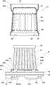
図1〜図13は実施例1を示す。1はサイクロン式電気掃除機である。この電気掃除機1は、掃除機本体2と、この掃除機本体2の前部に着脱自在に取り付けられる集塵容器3と、この集塵容器3に着脱可能に取り付けられるフィルタ組立体4とを備える。なお、前記フィルタ組立体4は、前記集塵容器3に対しバヨネット結合によって取り付けられている。  1 to 13 show a first embodiment. 1 is a cyclone type vacuum cleaner. Thevacuum cleaner 1 includes avacuum cleaner body 2, adust collection container 3 that is detachably attached to a front portion of thevacuum cleaner body 2, and afilter assembly 4 that is detachably attached to thedust collection container 3. Prepare. Thefilter assembly 4 is attached to thedust collecting container 3 by bayonet coupling.

前記掃除機本体2は、電動送風機5が内蔵されたケース6と、把持部7と、電源コード8とを有して構成されている。また、前記把持部7には、前記集塵容器3を着脱するための操作部9及びスイッチ操作部10が設けられている。そして、このスイッチ操作部10を操作することにより、前記電動送風機5が駆動する。  Thevacuum cleaner body 2 includes acase 6 in which an electric blower 5 is built, agrip portion 7, and apower cord 8. In addition, thegrip portion 7 is provided with anoperation portion 9 and aswitch operation portion 10 for attaching and detaching thedust collecting container 3. The electric blower 5 is driven by operating theswitch operation unit 10.

前記集塵容器3は、一端(後端)が開放し、他端(前端)が閉塞した有底筒状に形成され、略円筒形の周壁部11と、この周壁部11の前側を閉塞する前面部12とを一体に備えている。なお、これらの周壁部11及び前面部12は、比較的硬質で透光性を有する合成樹脂により一体成型される。また、前記前面部12には、不透光性の飾り板13が取り付けられている。  Thedust collecting container 3 is formed in a bottomed cylindrical shape with one end (rear end) open and the other end (front end) closed, and closes the substantially cylindricalperipheral wall portion 11 and the front side of theperipheral wall portion 11. Thefront part 12 is provided integrally. Note that theperipheral wall portion 11 and thefront surface portion 12 are integrally molded with a relatively hard and translucent synthetic resin. Further, a translucentdecorative plate 13 is attached to thefront surface portion 12.

前記周壁部11の後側には、気流を前記周壁部11の周方向に導入する導入部14を連通形成し、この導入部14に、吸引経路が内部に設けられた接続筒部15を接続すると共に、この接続筒部15を前記周壁部11の外周に固定している。また、前記接続筒部15の前側部15Aは前後方向に向くと共に、前記接続筒部15の後側部15Bは前記集塵容器3の周方向に向いている。そして、前記接続筒部15の前端には、ノズル16が着脱可能に設けられる。  Anintroduction part 14 for introducing an air flow in the circumferential direction of theperipheral wall part 11 is formed in communication with the rear side of theperipheral wall part 11, and aconnection cylinder part 15 provided with a suction path is connected to theintroduction part 14. In addition, the connectingtube portion 15 is fixed to the outer periphery of theperipheral wall portion 11. Further, thefront side portion 15 </ b> A of theconnection tube portion 15 faces in the front-rear direction, and therear side portion 15 </ b> B of theconnection tube portion 15 faces in the circumferential direction of thedust collecting container 3. And thenozzle 16 is provided in the front end of the saidconnection cylinder part 15 so that attachment or detachment is possible.

前記フィルタ組立体4は、筒状体21と、内フィルタ体22とを備える。前記筒状体21は、一端が開放し、他端が閉塞した有底円筒状に形成され、略円筒形の周壁部23と、この周壁部23の前側を閉塞する前面部24と、前記周壁部23の前側に設けた返し部25とを一体に備えている。なお、これらの周壁部23、前面部24及び返し部25は、比較的硬質の合成樹脂により一体成型される。そして、前記筒状体21の周壁部23及び前記集塵容器3の周壁部11は、前側に向かって径がやや縮小するように形成されている。また、前記筒状体21の周壁部23には、一次フィルタとして作用する多数の小孔23Hが複数穿設されている。  Thefilter assembly 4 includes acylindrical body 21 and aninner filter body 22. Thecylindrical body 21 is formed in a bottomed cylindrical shape with one end open and the other end closed, a substantially cylindricalperipheral wall portion 23, afront surface portion 24 closing the front side of theperipheral wall portion 23, and the peripheral wall Thereturn part 25 provided in the front side of thepart 23 is provided integrally. Theperipheral wall portion 23, thefront surface portion 24, and thereturn portion 25 are integrally formed of a relatively hard synthetic resin. And the surroundingwall part 23 of the saidcylindrical body 21 and the surroundingwall part 11 of the saiddust collection container 3 are formed so that a diameter may reduce a little toward the front side. In addition, a plurality ofsmall holes 23H that act as primary filters are formed in theperipheral wall portion 23 of thecylindrical body 21.

更に、前記返し部25は、前記周壁部23から連続して徐々に径が大きくなる拡径部25Aと、この拡径部25Aから連続して形成された短円筒部25Bとで構成されている。そして、前記集塵容器3内において、この集塵容器3に前記フィルタ組立体4を取り付けた際に、前記返し部25の短円筒部25Bの先端(前端)が位置する場所から前記集塵容器3の前面部12までの空間が、塵埃貯溜部26となる。  Further, thereturn portion 25 is composed of an enlargeddiameter portion 25A having a diameter that gradually increases continuously from theperipheral wall portion 23, and a shortcylindrical portion 25B that is formed continuously from the enlargeddiameter portion 25A. . Then, when thefilter assembly 4 is attached to thedust collection container 3 in thedust collection container 3, the dust collection container starts from the position where the tip (front end) of the shortcylindrical portion 25B of thereturn portion 25 is located. The space up to thefront surface portion 12 is adust storage portion 26.

また、前記周壁部23には、その開口縁部27を拡大する拡大段部28を設け、この拡大段部28の前側より後側が一段大きくなるように形成されている。そして、前記開口縁部27の内面には、円周方向に等間隔で複数のバヨネット用突起29が設けられている。なお、この例では、4つのバヨネット用突起29が設けられている。  Further, theperipheral wall portion 23 is provided with an enlargedstep portion 28 for enlarging theopening edge portion 27, and the rear side of the enlargedstep portion 28 is formed to be larger by one step. A plurality ofbayonet protrusions 29 are provided on the inner surface of theopening edge 27 at equal intervals in the circumferential direction. In this example, fourbayonet protrusions 29 are provided.

前記内フィルタ体22は、不織布等からなる筒状のフィルタ本体31と、このフィルタ本体31の前部開口を閉塞する蓋部32と、前記フィルタ本体31の後部に一体に設けたリング状の取付部33とを備えている。なお、前記フィルタ本体31は谷部と山部を交互に形成した蛇腹状をなし、前記蓋部32と取付部33は比較的硬質な合成樹脂からなる。  Theinner filter body 22 includes atubular filter body 31 made of nonwoven fabric, alid 32 that closes the front opening of thefilter body 31, and a ring-shaped attachment integrally provided at the rear of thefilter body 31.Part 33. Thefilter body 31 has a bellows shape in which valleys and peaks are alternately formed, and thelid part 32 and theattachment part 33 are made of a relatively hard synthetic resin.

前記取付部33は、鍔部34の前側に、比較的短い前外筒部35Sと前内筒部35Uとを突設し、これら前外筒部35Sと前内筒部35Uとの間に、前記フィルタ本体31の後部を接着等により固着している。なお、前記前外筒部35Sと前内筒部35Uは、それぞれ前記鍔部34と同軸状に設けられている。そして、前記前内筒部35U内には、後述する吸込筒部64と接続する接続孔36が設けられている。  The mountingportion 33 is provided with a relatively short frontouter cylinder portion 35S and a frontinner cylinder portion 35U on the front side of theflange portion 34, and between the frontouter cylinder portion 35S and the frontinner cylinder portion 35U, The rear part of thefilter body 31 is fixed by bonding or the like. The frontouter cylinder part 35S and the frontinner cylinder part 35U are provided coaxially with theflange part 34, respectively. Aconnection hole 36 is provided in the frontinner cylinder part 35U to connect to asuction cylinder part 64 described later.

前記前外筒部35Sの外周には、前記バヨネット用突起29に対応して、バヨネット用溝37が設けられている。このバヨネット用溝37は、前記前外筒部35Sの前縁で開口する溝入口37Aと、この溝入口37Aに連通し前記前外筒部35Sの外周に沿って円周方向に延設される係止溝部37Bを有する。  Abayonet groove 37 is provided on the outer periphery of the front outer cylinder portion 35 </ b> S so as to correspond to thebayonet protrusion 29. Thebayonet groove 37 extends in the circumferential direction along the outer periphery of the frontouter cylinder portion 35S, which communicates with thegroove inlet 37A and opens at the front edge of the frontouter cylinder portion 35S. A lockinggroove 37B is provided.

そして、前記フィルタ本体31に前記筒状体21を被せるようにして、前記バヨネット用突起29を前記溝入口37Aに挿入し、前記筒状体21を前記係止溝部37Bの延設方向に回すことにより、前記係止溝部37Bに前記バヨネット用突起29が係止する。これによって、前記筒状体21に前記内フィルタ体22が結合される。  Then, thebayonet protrusion 29 is inserted into thegroove inlet 37A so as to cover thetubular body 21 on thefilter body 31, and thetubular body 21 is rotated in the extending direction of the lockinggroove portion 37B. As a result, thebayonet protrusion 29 is locked in the lockinggroove 37B. As a result, theinner filter body 22 is coupled to thecylindrical body 21.

なお、前記筒状体21は、前側から見て、前記内フィルタ体22に対し時計回り方向に回動させることで固定され、反時計回り方向に回動させることで取り外し可能となる。このように、バヨネット結合とは、いわゆる「抜き挿し」と「ひねり」を組み合わせて、前記筒状体21と前記内フィルタ体22の結合・分離を行うことができる結合構造である。  Thecylindrical body 21 is fixed by rotating clockwise with respect to theinner filter body 22 when viewed from the front side, and can be removed by rotating counterclockwise. Thus, the bayonet coupling is a coupling structure in which thetubular body 21 and theinner filter body 22 can be coupled / separated by combining so-called “insertion / removal” and “twist”.

また、前記鍔部34には、後側に短い後外筒部41Sと後内筒部41Uが突設されている。前記後外筒部41Sは、前記鍔部34の外周縁部に設けた環状壁部である。また、前記後内筒部41Uは、前記前内筒部35Uより大径である。そして、前記後外筒部41Sの外面には、円周方向に等間隔で複数のバヨネット用突起42が設けられている。なお、この例では4つの前記バヨネット用突起42が設けられている。また、図6に示すように、前記後内筒部41Uと前外筒部35Sは、ほぼ同径である。  Further, theflange portion 34 is provided with a short rearouter cylinder portion 41S and a rearinner cylinder portion 41U on the rear side. The rear outer cylinder portion 41 </ b> S is an annular wall portion provided on the outer peripheral edge portion of theflange portion 34. The rearinner cylinder portion 41U has a larger diameter than the frontinner cylinder portion 35U. A plurality ofbayonet protrusions 42 are provided on the outer surface of the rearouter cylinder portion 41S at equal intervals in the circumferential direction. In this example, fourbayonet protrusions 42 are provided. Moreover, as shown in FIG. 6, the said rearinner cylinder part 41U and the frontouter cylinder part 35S are substantially the same diameter.

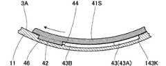
前記集塵容器3の周壁部11における開口縁部3A側の内周には、前記バヨネット用突起42に対応して、バヨネット用溝43が設けられている。このバヨネット用溝43は、前記周壁部11の開口縁部3Aで開口する溝入口43Aと、この溝入口43Aに連通し前記周壁部11の内周に沿って円周方向に延設される係止溝部43Bとを有する。前記溝入口43Aは、係止溝部43B側に前後方向の段部143を有すると共に、前後方向に対して反係止溝部43B側に傾斜した傾斜段部143Kを有する。この傾斜段部143Kは、前記溝入口43Aが後方に向かって拡大するように傾斜し、前記バヨネット用突起42を前記溝入口43Aの前側に案内する。  Abayonet groove 43 is provided on the inner periphery of theperipheral wall 11 of thedust collecting container 3 on theopening edge 3 </ b> A side corresponding to thebayonet protrusion 42. Thebayonet groove 43 includes agroove inlet 43A that is opened at theopening edge 3A of theperipheral wall portion 11, and a member that communicates with thegroove inlet 43A and extends in the circumferential direction along the inner periphery of theperipheral wall portion 11. And astop groove portion 43B. Thegroove inlet 43A has astep portion 143 in the front-rear direction on the lockinggroove portion 43B side and aninclined step portion 143K inclined toward theanti-locking groove portion 43B side with respect to the front-rear direction. Theinclined step portion 143K is inclined so that thegroove inlet 43A expands rearward, and guides thebayonet protrusion 42 to the front side of thegroove inlet 43A.

なお、前記段部143は集塵容器3の軸方向とほぼ平行に形成されている。また、上述したように、前記バヨネット用溝43は、前記周壁部11の内周に設けられているが、この周壁部11が透光性を有する材料からなるから、一部、外側から見た図面でも、前記バヨネット用溝43等を実線で図示している。  Thestep 143 is formed substantially parallel to the axial direction of thedust collecting container 3. Further, as described above, thebayonet groove 43 is provided on the inner periphery of theperipheral wall portion 11, but since theperipheral wall portion 11 is made of a light-transmitting material, a part thereof is viewed from the outside. In the drawing, thebayonet groove 43 and the like are shown by solid lines.

また、複数の前記係止溝部43Bの少なくとも1つには、この係止溝部43Bの先端側に突部44が設けられている。なお、係止溝部43Bの先端43Sと前記突部44との間隔は、前記バヨネット用突起42の周方向の幅に対応している。また、前記周壁部11の開口縁部3A側の内周には、前記鍔部34が当接する段部45が形成されている。なお、前記段部45は、前記周壁部11の他部の内面より外周側に位置している。  Further, at least one of the plurality of lockinggroove portions 43B is provided with aprotrusion 44 on the distal end side of the lockinggroove portion 43B. The interval between thetip 43S of the lockinggroove 43B and theprotrusion 44 corresponds to the circumferential width of thebayonet protrusion 42. Further, astep portion 45 with which theflange portion 34 abuts is formed on the inner periphery of theperipheral wall portion 11 on theopening edge portion 3A side. Thestep 45 is located on the outer peripheral side from the inner surface of the other part of theperipheral wall 11.

そして、前記集塵容器3内に前記フィルタ組立体4を挿入し、前記バヨネット用突起42を前記溝入口43Aに挿入すると、前記段部45に前記鍔部34が当接し、それ以上挿入することができなくなる。この位置で前記フィルタ組立体4を前記係止溝部43Bの先端43S側に回すことにより、前記係止溝部43Bに前記バヨネット用突起42が係止されて、前記集塵容器3に前記フィルタ組立体4が結合される。この場合、前記フィルタ組立体4を回動させると、前記バヨネット用突起42が前記突部44を乗り越える際、前記バヨネット用突起42側が弾性変形してクリック感が得られるので、前記集塵容器3とフィルタ組立体4の結合を確認することができる。  Then, when thefilter assembly 4 is inserted into thedust collecting container 3 and thebayonet protrusion 42 is inserted into thegroove inlet 43A, theflange portion 34 abuts on thestep portion 45 and is inserted further. Can not be. By rotating thefilter assembly 4 toward thefront end 43S of the lockinggroove 43B at this position, thebayonet protrusion 42 is locked to the lockinggroove 43B, and the filter assembly is attached to thedust collecting container 3. 4 are combined. In this case, when thefilter assembly 4 is rotated, when thebayonet protrusion 42 gets over theprotrusion 44, thebayonet protrusion 42 side is elastically deformed to provide a click feeling. And the coupling of thefilter assembly 4 can be confirmed.

なお、前記フィルタ組立体4は、前記開口縁部3A側、即ち後側から見て、前記集塵容器3に対し、時計回り方向に回動させることで固定され、反時計回り方向に回動させることで取り外し可能となる。そして、前記バヨネット用突起42とバヨネット用溝43とにより、バヨネット結合機構46を構成している。  Thefilter assembly 4 is fixed by rotating clockwise with respect to thedust collecting container 3 when viewed from theopening edge 3A side, that is, the rear side, and rotates counterclockwise. It becomes possible to remove it. Thebayonet protrusion 42 and thebayonet groove 43 constitute abayonet coupling mechanism 46.

前記集塵容器3の周壁部11の開口縁部3Aには、前記溝入口43Aに近接して、第一切欠部51が設けられる。この第一切欠部51は、前後方向の縦縁部51Aを周方向両側に有すると共に、両側の縦縁部51A,51Aの底部を連結する横縁部51Bを有する。そして、前記開口縁部3Aと縦縁部51Aとの間には、湾曲状の面取り部51Mを設けている。また、前記後外筒部41Sの開口縁部41Kには、前記第一切欠部51とほぼ同一形状の第二切欠部52が設けられている。この第二切欠部52は、前後方向の縦縁部52Aを周方向両側に有すると共に、両側の縦縁部52A,52Aの底部を連結する横縁部52Bを有する。そして、前記開口縁部41Kと縦縁部52Aとの間には、湾曲状の面取り部52Mを設けている。  Theopening edge 3A of theperipheral wall 11 of thedust collecting container 3 is provided with afirst notch 51 in the vicinity of thegroove inlet 43A. Thefirst notch 51 has alongitudinal edge 51A in the front-rear direction on both sides in the circumferential direction and alateral edge 51B that connects the bottoms of thelongitudinal edges 51A and 51A on both sides. A curved chamfer 51M is provided between the openingedge 3A and thevertical edge 51A. Asecond notch 52 having substantially the same shape as thefirst notch 51 is provided at theopening edge 41K of the rearouter cylinder 41S. Thesecond notch 52 has alongitudinal edge 52A in the front-rear direction on both sides in the circumferential direction, and alateral edge 52B that connects the bottoms of thelongitudinal edges 52A and 52A on both sides. A curved chamferedportion 52M is provided between the openingedge portion 41K and thevertical edge portion 52A.

そして、前記バヨネット用突起42を前記溝入口43Aに挿入した位置では、前記第一切欠部51を前記後外筒部41Sがほぼ塞ぎ、前記バヨネット用突起42が係止溝部43Bの先端43Sと突部44との間に係止された位置では、前記第一切欠部51と第二切欠部52とが重なり合う。なお、図8に示すように、前記集塵容器3に前記フィルタ組立体4を取り付けた状態で、前記開口縁部3Aは前記開口縁部41Kより後側に位置する。また、図6等に示すように、前記取付部33を基準にして、前記後内筒部41Uの開口縁部41K´は、前記後外筒部41Sの開口縁部41Kより後側に位置する。  At the position where thebayonet projection 42 is inserted into thegroove inlet 43A, the rearouter cylinder portion 41S substantially closes thefirst notch 51, and thebayonet projection 42 is connected to thetip 43S of the lockinggroove portion 43B. Thefirst notch 51 and thesecond notch 52 overlap at a position locked with theprotrusion 44. As shown in FIG. 8, theopening edge 3A is located behind the openingedge 41K in a state where thefilter assembly 4 is attached to thedust collecting container 3. Further, as shown in FIG. 6 and the like, the openingedge portion 41K ′ of the rearinner cylinder portion 41U is located on the rear side of the openingedge portion 41K of the rearouter cylinder portion 41S with respect to the mountingportion 33. .

前記後内筒部41Uの開口縁部41K´には、前記第二切欠部52とほぼ同一形状の第三切欠部53が設けられている。また、前記鍔部34における前記後内筒部41Uの内側には、当接筒部54が設けられている。なお、この当接筒部54は、後述する吸込筒部64の弾性シール材65に当接する。  Athird notch 53 having substantially the same shape as thesecond notch 52 is provided at theopening edge 41K ′ of the rearinner cylinder 41U. Further, anabutting cylinder portion 54 is provided inside the rearinner cylinder portion 41U in thecollar portion 34. In addition, thiscontact cylinder part 54 is contact | abutted to theelastic sealing material 65 of thesuction cylinder part 64 mentioned later.

前記取付部33の外周には、環状の弾性シール部材55が取り付けられている。このシール部材55は、前記フィルタ組立体4を前記集塵容器3に挿入した際に、その外周部が前記集塵容器3の周壁部11の内面に密着するように構成されている。  An annularelastic seal member 55 is attached to the outer periphery of theattachment portion 33. Theseal member 55 is configured such that when thefilter assembly 4 is inserted into thedust collection container 3, the outer peripheral portion thereof is in close contact with the inner surface of theperipheral wall portion 11 of thedust collection container 3.

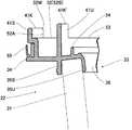
前記掃除機本体2の前側には、前記集塵容器3を着脱自在に取り付ける装着部61が設けられている。この装着部61は、底面部62と筒状部63とを備える。前記底面部62の中央には、前記電動送風機5の吸い込み口である吸込筒部64が突設され、この吸込筒部64の上縁にリング状の弾性シール材65を設けている。そして、前記装着部61に前記集塵容器3を装着した状態で、前記当接筒部54が前記弾性シール材65に当接して前記吸込筒部64と前記接続孔36がシール状態で接続される。また、前記吸込筒部64の外側に前記後内筒部41Uが位置する。なお、前記吸込筒部64の吸込口には、塵埃用のフィルタ64Fが設けられている。  On the front side of thecleaner body 2, a mountingportion 61 for detachably attaching thedust collecting container 3 is provided. The mountingportion 61 includes abottom surface portion 62 and acylindrical portion 63. At the center of thebottom surface portion 62, asuction cylinder portion 64 that is a suction port of the electric blower 5 protrudes, and a ring-shapedelastic sealing material 65 is provided on the upper edge of thesuction cylinder portion 64. Then, in a state where thedust collecting container 3 is mounted on the mountingportion 61, thecontact cylinder portion 54 contacts theelastic seal member 65, and thesuction cylinder portion 64 and theconnection hole 36 are connected in a sealed state. The Further, the rearinner cylinder portion 41U is located outside thesuction cylinder portion 64. Afilter 64F for dust is provided at the suction port of thesuction cylinder portion 64.

前記装着部61の筒状部63には、前記導入部14及び前記接続筒部15を収納する凹部63Aが設けられている。また、前記筒状部63は、外周部66と、この外周部66の内面に設けた前後方向の縦リブ部67Tと、外周部66の内面に設けた周方向の横リブ部67Yとを備えている。前記縦リブ部67Tは、周方向に間隔を置いて複数設けられている。また、前記横リブ部67Yは、前後方向に間隔を置いて複数設けられている。  Thecylindrical portion 63 of the mountingportion 61 is provided with aconcave portion 63 </ b> A that accommodates theintroduction portion 14 and theconnection cylinder portion 15. Thetubular portion 63 includes an outerperipheral portion 66, a longitudinal rib portion 67 </ b> T in the front-rear direction provided on the inner surface of the outerperipheral portion 66, and a lateral rib portion 67 </ b> Y in the circumferential direction provided on the inner surface of the outerperipheral portion 66. ing. A plurality of thevertical rib portions 67T are provided at intervals in the circumferential direction. A plurality of thelateral rib portions 67Y are provided at intervals in the front-rear direction.

図12に示すように、前記筒状部63の内周には、前記把持部7の位置に中央縦溝部71を形成すると共に、この中央縦溝部71の左右には、それぞれ左縦溝部72L及び右縦溝部72Rを形成している。これらの溝部71,72L,72Rは、前記掃除機本体2側の位置決め部であって、前後方向に形成されている。一方、前記集塵容器3の周壁部11の外周には、前記縦溝部71,72L,72Rに前方から挿入される中央突条部73、左突条部74L及び右突条部74Rが設けられている。そして、これら突条部73,74L,74Rが前記集塵容器3側の位置決め部である。  As shown in FIG. 12, a centralvertical groove 71 is formed in the inner periphery of thetubular portion 63 at the position of thegripping portion 7, and left and rightvertical grooves 72L and 72L are provided on the left and right of the centralvertical groove 71, respectively. A rightvertical groove 72R is formed. Thesegroove parts 71, 72L, 72R are positioning parts on thecleaner body 2 side, and are formed in the front-rear direction. On the other hand, acentral ridge 73, aleft ridge 74L, and aright ridge 74R inserted from the front into thevertical groove portions 71, 72L, 72R are provided on the outer periphery of theperipheral wall portion 11 of thedust collecting container 3. ing. And theseprotrusion part 73,74L, 74R is a positioning part by the side of the saiddust collection container 3. As shown in FIG.

前記中央突条部73の先端側には、傾斜案内部73Aを設けている。この傾斜案内部73Aの基端側には、前記中央突条部73の長さ方向に対し交差する方向で溝状をなす係止受部73Bを設けている。前記中央縦溝部71には、別体の係止部材75を配置すると共に、この係止部材75には、前記係止受部73Bに係脱可能な略鉤形の係止部75Bを一体に有している。この係止部75Bの先端側には、前記傾斜案内部73Aが当接する傾斜案内部75Aが設けられている。また、前記係止部材75は、左右方向に移動可能に設けられ、前記係止部75Bが前記係止受部73Bに係止するように、図12における右方向に、付勢手段(図示せず)により付勢されている。そして、前記操作部9を図12における左方向に押す操作をすることにより、前記係止部75Bが移動して、前記係止受部73Bから外れ、前記装着部61から前記集塵容器3を取り外すことができる。  Aninclined guide portion 73 </ b> A is provided on the distal end side of thecentral ridge portion 73. On the base end side of theinclined guide portion 73A, alocking receiving portion 73B having a groove shape in a direction intersecting the length direction of thecentral protrusion 73 is provided. Aseparate locking member 75 is disposed in the centrallongitudinal groove 71, and a substantially bowl-shapedlocking portion 75B that can be engaged with and disengaged from thelocking receiving portion 73B is integrally formed on the lockingmember 75. Have. Aninclined guide portion 75A with which theinclined guide portion 73A abuts is provided on the distal end side of the lockingportion 75B. Further, the lockingmember 75 is provided so as to be movable in the left-right direction, and an urging means (not shown) is provided in the right direction in FIG. 12 so that the lockingportion 75B is locked to thelocking receiving portion 73B. Z)). Then, by operating theoperation portion 9 to the left in FIG. 12, the lockingportion 75 </ b> B moves to disengage from thelocking receiving portion 73 </ b> B, and thedust collection container 3 is removed from the mountingportion 61. Can be removed.

また、前記中央突条部73は、1つの前記第一切欠部51と前後方向に並んで位置している。そして、前記底面部62には、前記掃除機本体2に前記集塵容器3を取り付けた際に、前記第一切欠部51に対応する前記中央縦溝部71の後方位置に、凸部81が設けられている。この凸部81は、前記装着部61の外周部66と前記吸込筒部64とを連結するように形成されている。また、前記凸部81は、前記横縁部51B,51B,52B,52B内に挿入する両側の側板部82,82と、両側の側板部82,82を連結する上面部83とを備えている。また、この上面部83の上部中央には、凸状の湾曲面部83Wが形成されている。更に、前記凸部81の幅方向端部には、前記側板部82,82と上面部83の角部に湾曲面からなる案内部81Kが形成されている。この案内部81Kは、前記第二切欠部52の面取り部52Mに当接可能なものである。  Further, thecentral protrusion 73 is positioned side by side with the onefirst notch 51 in the front-rear direction. And, when thedust collecting container 3 is attached to thevacuum cleaner body 2, thebottom portion 62 has aconvex portion 81 at a rear position of the centralvertical groove portion 71 corresponding to thefirst notch 51. Is provided. Theconvex portion 81 is formed so as to connect the outerperipheral portion 66 of the mountingportion 61 and thesuction cylinder portion 64. Theconvex portion 81 includesside plate portions 82 and 82 on both sides to be inserted into thelateral edge portions 51B, 51B, 52B and 52B, and anupper surface portion 83 for connecting theside plate portions 82 and 82 on both sides. . A convexcurved surface portion 83 </ b> W is formed at the upper center of theupper surface portion 83. Furthermore, aguide portion 81K made of a curved surface is formed at the corners of theside plate portions 82 and 82 and theupper surface portion 83 at the end in the width direction of theconvex portion 81. Theguide portion 81K can come into contact with the chamferedportion 52M of thesecond cutout portion 52.

前記凸部81は、前記底面部62に膨出形成されており、前記凸部81を利用して安全弁装置を構成している。具体的には、図2に示すように、前記凸部81は弁ケース84の一部を構成している。この弁ケース84は、その外側の開閉口85が前記掃除機本体2の外部に連通すると共に、内側に通気孔86を設けている。また、この通気孔86は、前記電動送風機5の吸込筒部64の側面に連通している。そして、前記弁ケース84内に前記開閉口85を開閉する弁体87を設けている。この弁体87は、付勢手段(図示せず)により、前記開閉口85に当接してこの開閉口85を塞ぐ方向に付勢されている。  Theconvex portion 81 bulges on thebottom surface portion 62, and constitutes a safety valve device using theconvex portion 81. Specifically, as shown in FIG. 2, theconvex portion 81 constitutes a part of thevalve case 84. Thevalve case 84 has an outer opening /closing port 85 communicating with the outside of thecleaner body 2 and avent hole 86 provided on the inner side. Further, thevent hole 86 communicates with the side surface of thesuction cylinder portion 64 of the electric blower 5. Avalve body 87 for opening and closing the opening /closing port 85 is provided in thevalve case 84. Thevalve body 87 is urged by an urging means (not shown) so as to abut against the opening /closing port 85 and close the opening /closing port 85.

そして、前記電動送風機5の駆動中に、前記ノズル16等が詰まって前記吸込筒部64から外気を吸引できなくなり、前記掃除機本体2のケース6内が所定値以下の負圧になると、前記弁体87が図2中下方に移動して前記開閉口85が開き、外気を導入する。このように動作することで、前記電動送風機5に負荷が掛かることを防止できる。なお、前記掃除機本体2のケース6の後部には、排気口88が設けられている。  And while the electric blower 5 is being driven, thenozzle 16 and the like are clogged, and it becomes impossible to suck the outside air from thesuction tube portion 64, and the inside of thecase 6 of thecleaner body 2 becomes a negative pressure of a predetermined value or less. Thevalve body 87 moves downward in FIG. 2 and the opening /closing port 85 is opened to introduce outside air. By operating in this way, it is possible to prevent the electric blower 5 from being loaded. Anexhaust port 88 is provided in the rear part of thecase 6 of thecleaner body 2.

次に、前記掃除機1の使用方法につき、前記集塵容器3の着脱方法を中心に説明する。前記フィルタ組立体4を組み立てるには、前記内フィルタ体22に前記筒状体21を被せるようにして、前記バヨネット用突起29を溝入口37Aに挿入し、前記筒状体21を係止溝部37Bの延設方向に回す。これにより、前記係止溝部37Bに前記バヨネット用突起29が係合して、前記筒状体21に前記内フィルタ体22が結合され、前記フィルタ組立体4が組み立てられる。  Next, how to use thevacuum cleaner 1 will be described focusing on how to attach and detach thedust collecting container 3. In order to assemble thefilter assembly 4, thebayonet protrusion 29 is inserted into thegroove inlet 37 </ b> A so as to cover theinner filter body 22 with thetubular body 21, and thetubular body 21 is inserted into the lockinggroove portion 37 </ b> B. Turn in the extending direction. As a result, thebayonet protrusion 29 engages with the lockinggroove 37B, theinner filter body 22 is coupled to thetubular body 21, and thefilter assembly 4 is assembled.

次に、前記集塵容器3に前記フィルタ組立体4を取り付けるには、前記集塵容器3内に前記フィルタ組立体4を挿入し、前記段部45に前記鍔部34が当接するまで前記バヨネット用突起42を前記溝入口43Aに挿入し、前記フィルタ組立体4を前記係止溝部43Bの先端43S側に回す。これにより、前記係止溝部43Bに前記バヨネット用突起42が係合して、前記集塵容器3に前記フィルタ組立体4が結合される。  Next, in order to attach thefilter assembly 4 to thedust collection container 3, thefilter assembly 4 is inserted into thedust collection container 3, and the bayonet is moved until theflange portion 34 comes into contact with the steppedportion 45. Theprojection 42 is inserted into thegroove inlet 43A, and thefilter assembly 4 is rotated toward thetip 43S of the lockinggroove 43B. As a result, thebayonet protrusion 42 is engaged with the lockinggroove 43B, and thefilter assembly 4 is coupled to thedust collecting container 3.

このように、前記フィルタ組立体4を集塵容器3に正しく取り付け、前記集塵容器3を前記装着部61に装着する場合は、前記掃除機本体2の縦溝部71,72L,72Rに前記集塵容器3の突条部73,74L,74Rを合わせて前記筒状部63内に前記集塵容器3を前後方向に沿って挿入する。この際、前記中央縦溝部71の係止部材75の傾斜案内部75Aに、前記中央突条部73の傾斜案内部73Aが当接し、前記中央突条部73に押されて係止部材75が非係止位置に移動し、前記傾斜案内部73Aが通過した後、前記係止部75Bが係止受部73Bと係合する。この位置で、前記第一及び第二切欠部51,52に前記凸部81が入る。  As described above, when thefilter assembly 4 is correctly attached to thedust collecting container 3 and thedust collecting container 3 is attached to theattachment portion 61, thedust collection container 3 is attached to thevertical groove portions 71, 72 </ b> L, 72 </ b> R of thecleaner body 2. Thedust collecting container 3 is inserted along the front-rear direction into thecylindrical part 63 with theprotrusions 73, 74L, 74R of thedust container 3 being aligned. At this time, theinclined guide portion 73A of thecentral ridge portion 73 abuts on theinclined guide portion 75A of the lockingmember 75 of the centrallongitudinal groove portion 71, and the lockingmember 75 is pushed by thecentral ridge portion 73. After moving to the non-locking position and passing through theinclined guide portion 73A, the lockingportion 75B engages with thelocking receiving portion 73B. At this position, theconvex portion 81 enters the first andsecond cutout portions 51 and 52.

一方、前記集塵容器3とフィルタ組立体4とのバヨネット結合が不十分で、前記第一切欠部51に前記後外筒部41Sが重なり合っている場合は、前記係止部75Bが前記係止受部73Bに係合する前に、前記後外筒部41Sが前記凸部81に当接する。このため、前記係止受部73Bに前記係止部75Bが係合せず、前記装着部61に前記集塵容器3を取り付けることができない。これにより、使用者は前記集塵容器3を取り外し、バヨネット結合を確認してから再度前記集塵容器3を取り付けることとになる。即ち、前記集塵容器3とフィルタ組立体4とを不完全な組み立て状態で、前記掃除機本体2に取り付けることを防止できる。  On the other hand, when the bayonet coupling between thedust collecting container 3 and thefilter assembly 4 is insufficient and the rearouter cylinder portion 41S overlaps thefirst notch portion 51, the lockingportion 75B is engaged with theengagement portion 75B. The rearouter cylinder portion 41S comes into contact with theconvex portion 81 before engaging with thestopper portion 73B. For this reason, the lockingportion 75B does not engage with thelocking receiving portion 73B, and thedust collecting container 3 cannot be attached to the mountingportion 61. As a result, the user removes thedust collection container 3, confirms the bayonet connection, and then attaches thedust collection container 3 again. That is, it is possible to prevent thedust collecting container 3 and thefilter assembly 4 from being attached to thecleaner body 2 in an incompletely assembled state.

また、図13(A)に示すように、前記第一切欠部51に前記後外筒部41Sが部分的に重なり合っている場合、前記後外筒部41Sの面取り部52Mが、前記凸部81の案内部81Kに当接すると、前記集塵容器3を押し込む力により、前記フィルタ組立体4が回転し、前記第一及び第二切欠部51,52が位置合わせされる。これによって、前記装着部61に前記集塵容器3を組み込むことができる。  Further, as shown in FIG. 13 (A), when the rearouter cylinder part 41S partially overlaps thefirst notch 51, thechamfered part 52M of the rearouter cylinder part 41S has the convex part. When abutting against theguide portion 81K of 81, thefilter assembly 4 is rotated by the force for pushing in thedust collecting container 3, and the first andsecond cutout portions 51 and 52 are aligned. As a result, thedust collecting container 3 can be incorporated into the mountingportion 61.

更に、万一、前記フィルタ組立体4を組み込まずに前記集塵容器3のみを前記装着部61に装着した場合、前記集塵容器3の開口縁部3Aに第一切欠部51を設けたから、前記筒状部63の内側と前記集塵容器3の外周との間の隙間を通って、前記第一切欠部51,51から前記集塵容器3内に空気が入り込む。このため、前記ノズル16から塵埃を含む気流を吸い込まず、塵埃を再び外気に撒き散らしたり、前記電動送風機5の効率を低下させたりすることがない。  Furthermore, in the unlikely event that only thedust collecting container 3 is mounted on the mountingportion 61 without incorporating thefilter assembly 4, thefirst notch 51 is provided at theopening edge 3 </ b> A of thedust collecting container 3. Through the gap between the inside of thecylindrical portion 63 and the outer periphery of thedust collecting container 3, air enters thedust collecting container 3 from thefirst notches 51 and 51. For this reason, the air current containing dust is not sucked from thenozzle 16, and the dust is not scattered again to the outside air, and the efficiency of the electric blower 5 is not reduced.

そして、前記装着部61に前記集塵容器3を正しく装着した状態で、前記スイッチ操作部10を操作して前記電動送風機5を駆動すると、前記ノズル16から吸引された塵埃を含む空気が、前記集塵容器3の周方向に接続した接続筒部15から前記集塵容器3に流れ込み、この集塵容器3内で渦流が形成され、この渦流に含まれる粗い塵埃が遠心分離され、前記周壁部11と返し部25との間から前記塵埃貯溜部26に移動すると共に、砂等の粗くて重い塵埃が分離された気流は、前記小孔23Hから前記筒状体21内に流入する。なお、気流が前記返し部25を乗り越える際に、この気流に含まれる塵埃の多くは、前記返し部25によって下方に返されることになる。そして、気流に含まれる軽い塵埃は、前記筒状体21内に流入する際に、一次フィルタとして作用する前記小孔23H、或いは前記フィルタ本体31によって捕捉される。このようにして、前記フィルタ本体31によって細かい塵埃が分離された清浄な気流は、前記フィルタ64Fを設けた吸込筒部64を通過して、前記電動送風機5に至る。なお、前記吸込筒部64から前記ケース6に吸い込まれた空気は、後部の前記排気口88から排出される。  When the electric blower 5 is driven by operating theswitch operation unit 10 in a state where thedust collecting container 3 is correctly mounted on the mountingunit 61, the air containing dust sucked from thenozzle 16 is From the connectingcylinder 15 connected in the circumferential direction of thedust collecting container 3, the dust flows into thedust collecting container 3, and a vortex is formed in thedust collecting container 3, and coarse dust contained in the vortex is centrifuged, and theperipheral wall 11 and thereturn part 25 move to thedust storage part 26, and airflow from which coarse and heavy dust such as sand is separated flows into thecylindrical body 21 from thesmall hole 23H. In addition, when an airflow gets over the saidreturn part 25, much dust contained in this airflow is returned below by the saidreturn part 25. FIG. Light dust contained in the airflow is captured by thesmall holes 23H acting as a primary filter or the filtermain body 31 when flowing into thecylindrical body 21. Thus, the clean airflow from which fine dust has been separated by thefilter body 31 passes through thesuction cylinder portion 64 provided with thefilter 64F and reaches the electric blower 5. The air sucked into thecase 6 from thesuction cylinder portion 64 is discharged from theexhaust port 88 at the rear portion.

このように本実施例では、請求項1に対応して、掃除機本体2と、この掃除機本体2に対し着脱可能に取り付けられる集塵容器3と、この集塵容器3に対しバヨネット式に着脱されるフィルタ組立体4とを有する電気掃除機1において、前記集塵容器3の開口縁部3Aに第一切欠部51を設け、前記フィルタ組立体4の取付部33の外周縁部に環状壁部たる後外筒部41Sを設け、この後外筒部41Sに、前記集塵容器3に前記フィルタ組立体4をバヨネット結合により取り付けた位置で前記第一切欠部51に重なり合う第二切欠部52を設けると共に、前記掃除機本体2に、第一切欠部51に対応する凸部81を設けたから、前記集塵容器3に前記フィルタ組立体4を正しく取り付けると、前記集塵容器3の第一切欠部51と前記フィルタ組立体4の第二切欠部52とが位置合わせされ、この状態で前記集塵容器3を前記掃除機本体2に組み込むと、この掃除機本体2の凸部81に第一切欠部51が係合する。一方、前記第一切欠部51と第二切欠部52とがずれた状態で前記集塵容器3を前記掃除機本体2に組み込もうとしても、この掃除機本体2の凸部81に前記第一切欠部51が係合しないことで、前記集塵容器3を前記掃除機本体2に組み込むことができないため、前記集塵容器3と前記フィルタ組立体4が正しく結合されていないことが分かる。Thus, in this embodiment, corresponding to claim 1, thecleaner body 2, thedust collecting container 3 that is detachably attached to thecleaner body 2, and the bayonet type with respect to thedust collecting container 3 In thevacuum cleaner 1 having thedetachable filter assembly 4, afirst notch 51 is provided at theopening edge 3 </ b> A of thedust collecting container 3, and the outer peripheral edge of the mountingportion 33 of thefilter assembly 4 is provided. A rearouter cylinder portion 41S which is an annular wall portion is provided, and the secondouter cylinder portion 41Soverlaps thefirst notch portion 51at a position where thefilter assembly 4 is attached to thedust collecting container 3 by bayonet coupling . Since thenotch 52 is provided and theconvex part 81 corresponding to thefirst notch 51 is provided in thecleaner body 2, when thefilter assembly 4 is correctly attached to thedust container 3, thedust container 3first notch 51 and the filter When thedust collecting container 3 is assembled in the cleanermain body 2 in this state, thesecond notch 51 of the three-dimensional body 4 is aligned with theconvex portion 81 of the cleanermain body 2. Match. On the other hand, even if thedust collecting container 3 is to be assembled into thecleaner body 2 in a state where thefirst notch 51 and thesecond notch 52 are displaced, theprotrusion 81 of thecleaner body 2 Since thedust collecting container 3 cannot be incorporated into thecleaner body 2 because thefirst notch 51 is not engaged at all, thedust collecting container 3 and thefilter assembly 4 may not be properly coupled. I understand.

また、このように本実施例では、請求項2に対応して、前記第二切欠部52の幅寸法Wと前記凸部81の幅寸法WTとをほぼ等しく形成したから、前記フィルタ組立体4を前記掃除機本体2の正しい位置に配置することができる。  Further, in this embodiment, the width dimension W of thesecond notch portion 52 and the width dimension WT of theconvex portion 81 are formed substantially equal to the second aspect, corresponding to claim 2, and therefore thefilter assembly 4. Can be arranged at the correct position of thecleaner body 2.

なお、前記第二切欠部52の幅寸法Wと前記凸部81の幅寸法WTとがほぼ等しいとは、前記第二切欠部52の幅寸法Wが前記凸部の幅寸法WTの1倍以上〜1.3倍以内程度であることを示す。  The width dimension W of thesecond notch 52 and the width dimension WT of theprotrusion 81 are substantially equal to each other. The width dimension W of thesecond notch 52 is one or more times the width dimension WT of the protrusion. It shows that it is about -1.3 times or less.

更に、このように本実施例では、請求項3に対応して、前記凸部81の幅方向端部に、前記第二切欠部52の案内部81K,81Kを設けたから、前記第一切欠部51と第二切欠部52とが多少ずれていても、前記掃除機本体2に前記集塵容器3を組み込む際、前記凸部81の案内部81Kに前記第二切欠部52が案内されることで、前記フィルタ組立体4が回転して、前記集塵容器3に対し正しい位置に合わされる。これによって、前記集塵容器3が前記掃除機本体2に組み込むことができるようになる。  Further, in this embodiment, in correspondence with the third aspect, since theguide portions 81K and 81K of thesecond notch portion 52 are provided at the width direction end portion of theconvex portion 81, the first notch portion is completely removed. Even when theportion 51 and thesecond cutout portion 52 are slightly displaced, thesecond cutout portion 52 is guided to theguide portion 81K of theconvex portion 81 when thedust collecting container 3 is assembled into thecleaner body 2. As a result, thefilter assembly 4 is rotated and adjusted to the correct position with respect to thedust collecting container 3. As a result, thedust collecting container 3 can be incorporated into thecleaner body 2.

また、実施例上の効果として、前記溝入口43Aは、前記係止溝部43B側に前後方向の段部143を有すると共に、反係止溝部43B側に傾斜した傾斜段部143Kを有している。また、この傾斜段部143Kは、前記溝入口43Aが後方に向かって拡大するように傾斜している。これによって、前記バヨネット用突起42は、前記溝入口43Aに入れやすくされると共に、前記係止溝部43B側に案内される。また、複数の前記係止溝部43Bの少なくとも1つには、この係止溝部43Bの先端側に前記突部44が設けられているから、この突部44を前記バヨネット用突起42が乗り越えることにより、このバヨネット用突起42を正しい位置に位置決めできる。更に、前記筒状部63の内周には、前記把持部7に対応する位置に前記中央縦溝部71を形成すると共に、この中央縦溝部71の左右に前記左右縦溝部72L,72Rを形成し、これら縦溝部71,72L,72Rに対し前後方向に挿脱される前記中央突条部73及び前記左突条部74L,右突条部74Rが前記周壁部11の外周に設けられ、これら左右突条部74L,74Rが先端側(後側)に向かって幅狭になるように形成されているから、複数の前記縦溝部71,72L,72Rと突条部73,74L,74Rの係合により、前記装着部61に簡便且つ正しく前記集塵容器3を着脱することができる。  Further, as an effect of the embodiment, thegroove inlet 43A has astep part 143 in the front-rear direction on the lockinggroove part 43B side, and aninclined step part 143K inclined on theanti-locking groove part 43B side. . Theinclined step portion 143K is inclined so that thegroove inlet 43A expands rearward. Accordingly, thebayonet protrusion 42 is easily inserted into thegroove inlet 43A and guided to the lockinggroove 43B side. Further, since at least one of the plurality of lockinggroove portions 43B is provided with theprotrusion 44 on the tip side of the lockinggroove portion 43B, thebayonet protrusion 42 passes over theprotrusion 44. Thebayonet projection 42 can be positioned at the correct position. Further, the centralvertical groove 71 is formed at a position corresponding to thegripping portion 7 on the inner periphery of thecylindrical portion 63, and the left and right vertical groove portions 72 </ b> L and 72 </ b> R are formed on the left and right of the centralvertical groove 71. Thecentral ridge 73, theleft ridge 74L, and theright ridge 74R that are inserted in and removed from thelongitudinal grooves 71, 72L, 72R in the front-rear direction are provided on the outer periphery of theperipheral wall 11, and these left and right Since theprotrusions 74L and 74R are formed so as to become narrower toward the front end side (rear side), the plurality ofvertical groove parts 71, 72L and 72R and theprotrusions 73, 74L and 74R are engaged. Thus, thedust collecting container 3 can be easily and correctly attached to and detached from the mountingportion 61.

なお、本発明は以上の実施例に限定されるものではなく、発明の要旨の範囲内で種々の変形実施が可能である。例えば、上記実施例では、4つのバヨネット結合機構46を備えたものを示したが、バヨネット結合機構46の数は1つ以上であればよい。また、案内部を湾曲面により構成したが、側板部82を斜めに形成して案内部を構成してもよい。  In addition, this invention is not limited to the above Example, A various deformation | transformation implementation is possible within the range of the summary of invention. For example, in the above embodiment, the fourbayonet coupling mechanisms 46 are shown, but the number ofbayonet coupling mechanisms 46 may be one or more. Moreover, although the guide part was comprised by the curved surface, theside plate part 82 may be formed diagonally and a guide part may be comprised.

1 掃除機
2 掃除機本体
3 集塵容器
4 フィルタ組立体
33 取付部
41S 後外筒部(環状壁部)
42 バヨネット用突起
43 バヨネット用溝
46 バヨネット結合機構
51 第一切欠部
52 第二切欠部
81 凸部
81K 案内部
DESCRIPTION OFSYMBOLS 1Vacuum cleaner 2 Vacuum cleanermain body 3Dust collection container 4Filter assembly 33Attachment part 41S Rear outer cylinder part (annular wall part)
42Bayonet projection 43Bayonet groove 46Bayonet coupling mechanism 51First notch portion 52Second notch portion 81Convex portion 81K Guide portion

Claims (3)

Translated fromJapanese
掃除機本体と、この掃除機本体に対し着脱可能に取り付けられる集塵容器と、この集塵容器に対しバヨネット式に着脱されるフィルタ組立体とを有する電気掃除機において、
前記集塵容器の開口縁部に第一切欠部を設け、前記フィルタ組立体の取付部の外周縁部に環状壁部を設け、この環状壁部に、前記集塵容器に前記フィルタ組立体をバヨネット結合により取り付けた位置で前記第一切欠部に重なり合う第二切欠部を設けると共に、前記掃除機本体に、前記第一切欠部に対応する凸部を設けたことを特徴とする電気掃除機。
In a vacuum cleaner having a vacuum cleaner body, a dust collection container that is detachably attached to the vacuum cleaner body, and a filter assembly that is detachably attached to the dust collection container in a bayonet manner,
A first notch is provided at the opening edge of the dust collecting container, an annular wall is provided at the outer peripheral edge of the attachment part of the filter assembly, and the filter assembly is attached to thedust collecting container on the annular wall.A second cutout portion thatoverlaps the first cutout portionat a position attached by bayonet coupling is provided, and a convex portion corresponding to the first cutout portion is provided in the cleaner body. Vacuum cleaner.
前記第二切欠部の幅寸法と前記凸部の幅寸法とをほぼ等しく形成したことを特徴とする請求項1記載の電気掃除機。  The electric vacuum cleaner according to claim 1, wherein a width dimension of the second notch part and a width dimension of the convex part are substantially equal. 前記凸部の幅方向端部に、前記第二切欠部の案内部を設けたことを特徴とする請求項1又は2記載の電気掃除機。  The electric vacuum cleaner according to claim 1 or 2, wherein a guide portion for the second notch portion is provided at an end portion in the width direction of the convex portion.
JP2012216065A2012-09-282012-09-28 Electric vacuum cleanerActiveJP5994536B2 (en)

Priority Applications (1)

Application NumberPriority DateFiling DateTitle
JP2012216065AJP5994536B2 (en)2012-09-282012-09-28 Electric vacuum cleaner

Applications Claiming Priority (1)

Application NumberPriority DateFiling DateTitle
JP2012216065AJP5994536B2 (en)2012-09-282012-09-28 Electric vacuum cleaner

Publications (2)

Publication NumberPublication Date
JP2014068749A JP2014068749A (en)2014-04-21
JP5994536B2true JP5994536B2 (en)2016-09-21

Family

ID=50744577

Family Applications (1)

Application NumberTitlePriority DateFiling Date
JP2012216065AActiveJP5994536B2 (en)2012-09-282012-09-28 Electric vacuum cleaner

Country Status (1)

CountryLink
JP (1)JP5994536B2 (en)

Families Citing this family (5)

* Cited by examiner, † Cited by third party
Publication numberPriority datePublication dateAssigneeTitle
JP6347196B6 (en)*2014-09-302018-07-18工機ホールディングス株式会社 Portable cleaner
KR102350782B1 (en)*2017-07-042022-01-14엘지전자 주식회사Cleaner
US20220240741A1 (en)*2019-07-182022-08-04Koki Holdings Co., Ltd.Vacuum cleaner
CN113069039B (en)*2021-04-142023-04-11深圳市杉川机器人有限公司Filter screen cylinder and portable dust collector
CN114601397B (en)*2021-08-242023-06-30北京石头世纪科技股份有限公司Base station and cleaning robot system

Family Cites Families (7)

* Cited by examiner, † Cited by third party
Publication numberPriority datePublication dateAssigneeTitle
JPS5310169U (en)*1976-07-091978-01-27
JPS61181430A (en)*1985-02-081986-08-14松下電器産業株式会社 vacuum cleaner
JPH0335248Y2 (en)*1985-06-131991-07-25
JP3656836B2 (en)*2001-07-132005-06-08東芝テック株式会社 Vacuum cleaner
JP2003180583A (en)*2001-12-182003-07-02Toshiba Tec Corp Electric vacuum cleaner
JP2004089379A (en)*2002-08-302004-03-25Toshiba Tec Corp Electric vacuum cleaner
JP2005334450A (en)*2004-05-282005-12-08Toshiba Tec Corp Electric vacuum cleaner

Also Published As

Publication numberPublication date
JP2014068749A (en)2014-04-21

Similar Documents

PublicationPublication DateTitle
JP2016049141A (en)Vacuum cleaner
EP1674017B1 (en)Dust collection unit and vacuum cleaner with the same
JP5994536B2 (en) Electric vacuum cleaner
AU2012263910B2 (en)Vacuum Cleaner
JP2010508884A (en) Vacuum cleaning method
EP3849390B1 (en)Dust collecting apparatus and cleaner having the same
JP4320663B2 (en) Cyclone vacuum cleaner
JP7257798B2 (en) Cyclone unit
JP7549400B2 (en) Vacuum Cleaner System
JP4743668B2 (en) Cyclone vacuum cleaner
CN107847094B (en)Electric vacuum cleaner
KR100787062B1 (en) Vacuum filter unit
EP2708172A1 (en)Vacuum cleaner
JP2008136613A (en) Electric vacuum cleaner
CN101316542A (en) Centrifugal separator for vacuum cleaners with improved cover seal
JP6254436B2 (en) Electric vacuum cleaner
JP7627951B2 (en) Vacuum cleaner
KR100762328B1 (en) Handy vacuum cleaner all-in-one vacuum cleaner
KR100762326B1 (en) Handy Vacuum Cleaner
KR20060013785A (en) Dust collection unit for vacuum cleaner
KR20080040387A (en) Handy Vacuum Cleaner
KR100762324B1 (en) Vacuum cleaner
JP5540891B2 (en) Electric vacuum cleaner
CN101277637A (en) Centrifugal Separators for Vacuum Cleaners
KR100762325B1 (en) Handy cleaners and vacuum cleaners having the same

Legal Events

DateCodeTitleDescription
A621Written request for application examination

Free format text:JAPANESE INTERMEDIATE CODE: A621

Effective date:20150624

A977Report on retrieval

Free format text:JAPANESE INTERMEDIATE CODE: A971007

Effective date:20160121

A131Notification of reasons for refusal

Free format text:JAPANESE INTERMEDIATE CODE: A131

Effective date:20160209

A521Request for written amendment filed

Free format text:JAPANESE INTERMEDIATE CODE: A523

Effective date:20160407

TRDDDecision of grant or rejection written
A01Written decision to grant a patent or to grant a registration (utility model)

Free format text:JAPANESE INTERMEDIATE CODE: A01

Effective date:20160726

A61First payment of annual fees (during grant procedure)

Free format text:JAPANESE INTERMEDIATE CODE: A61

Effective date:20160808

R150Certificate of patent or registration of utility model

Ref document number:5994536

Country of ref document:JP

Free format text:JAPANESE INTERMEDIATE CODE: R150

R250Receipt of annual fees

Free format text:JAPANESE INTERMEDIATE CODE: R250

R250Receipt of annual fees

Free format text:JAPANESE INTERMEDIATE CODE: R250

R250Receipt of annual fees

Free format text:JAPANESE INTERMEDIATE CODE: R250

R250Receipt of annual fees

Free format text:JAPANESE INTERMEDIATE CODE: R250

R250Receipt of annual fees

Free format text:JAPANESE INTERMEDIATE CODE: R250

R250Receipt of annual fees

Free format text:JAPANESE INTERMEDIATE CODE: R250

R250Receipt of annual fees

Free format text:JAPANESE INTERMEDIATE CODE: R250


[8]ページ先頭

©2009-2025 Movatter.jp