JP5993535B2 - Endoscope bending portion and endoscope provided with the endoscope bending portion - Google Patents
Endoscope bending portion and endoscope provided with the endoscope bending portionDownload PDFInfo
- Publication number
- JP5993535B2 JP5993535B2JP2016522823AJP2016522823AJP5993535B2JP 5993535 B2JP5993535 B2JP 5993535B2JP 2016522823 AJP2016522823 AJP 2016522823AJP 2016522823 AJP2016522823 AJP 2016522823AJP 5993535 B2JP5993535 B2JP 5993535B2
- Authority
- JP
- Japan
- Prior art keywords
- bending
- tube
- endoscope
- end side
- distal end
- Prior art date
- Legal status (The legal status is an assumption and is not a legal conclusion. Google has not performed a legal analysis and makes no representation as to the accuracy of the status listed.)
- Active
Links
Images


Classifications
- A—HUMAN NECESSITIES
- A61—MEDICAL OR VETERINARY SCIENCE; HYGIENE
- A61B—DIAGNOSIS; SURGERY; IDENTIFICATION
- A61B1/00—Instruments for performing medical examinations of the interior of cavities or tubes of the body by visual or photographical inspection, e.g. endoscopes; Illuminating arrangements therefor
- A61B1/005—Flexible endoscopes
- A61B1/0051—Flexible endoscopes with controlled bending of insertion part
- A61B1/0057—Constructional details of force transmission elements, e.g. control wires
- A—HUMAN NECESSITIES
- A61—MEDICAL OR VETERINARY SCIENCE; HYGIENE
- A61B—DIAGNOSIS; SURGERY; IDENTIFICATION
- A61B1/00—Instruments for performing medical examinations of the interior of cavities or tubes of the body by visual or photographical inspection, e.g. endoscopes; Illuminating arrangements therefor
- A61B1/00112—Connection or coupling means
- A—HUMAN NECESSITIES
- A61—MEDICAL OR VETERINARY SCIENCE; HYGIENE
- A61B—DIAGNOSIS; SURGERY; IDENTIFICATION
- A61B1/00—Instruments for performing medical examinations of the interior of cavities or tubes of the body by visual or photographical inspection, e.g. endoscopes; Illuminating arrangements therefor
- A61B1/005—Flexible endoscopes
- A61B1/0051—Flexible endoscopes with controlled bending of insertion part
- A61B1/0055—Constructional details of insertion parts, e.g. vertebral elements
- A—HUMAN NECESSITIES
- A61—MEDICAL OR VETERINARY SCIENCE; HYGIENE
- A61B—DIAGNOSIS; SURGERY; IDENTIFICATION
- A61B1/00—Instruments for performing medical examinations of the interior of cavities or tubes of the body by visual or photographical inspection, e.g. endoscopes; Illuminating arrangements therefor
- A61B1/005—Flexible endoscopes
- A61B1/008—Articulations
- A—HUMAN NECESSITIES
- A61—MEDICAL OR VETERINARY SCIENCE; HYGIENE
- A61B—DIAGNOSIS; SURGERY; IDENTIFICATION
- A61B1/00—Instruments for performing medical examinations of the interior of cavities or tubes of the body by visual or photographical inspection, e.g. endoscopes; Illuminating arrangements therefor
- A61B1/267—Instruments for performing medical examinations of the interior of cavities or tubes of the body by visual or photographical inspection, e.g. endoscopes; Illuminating arrangements therefor for the respiratory tract, e.g. laryngoscopes, bronchoscopes
- A61B1/2676—Bronchoscopes
- A—HUMAN NECESSITIES
- A61—MEDICAL OR VETERINARY SCIENCE; HYGIENE
- A61M—DEVICES FOR INTRODUCING MEDIA INTO, OR ONTO, THE BODY; DEVICES FOR TRANSDUCING BODY MEDIA OR FOR TAKING MEDIA FROM THE BODY; DEVICES FOR PRODUCING OR ENDING SLEEP OR STUPOR
- A61M25/00—Catheters; Hollow probes
- A61M25/0009—Making of catheters or other medical or surgical tubes
- A61M25/0013—Weakening parts of a catheter tubing, e.g. by making cuts in the tube or reducing thickness of a layer at one point to adjust the flexibility
- A—HUMAN NECESSITIES
- A61—MEDICAL OR VETERINARY SCIENCE; HYGIENE
- A61M—DEVICES FOR INTRODUCING MEDIA INTO, OR ONTO, THE BODY; DEVICES FOR TRANSDUCING BODY MEDIA OR FOR TAKING MEDIA FROM THE BODY; DEVICES FOR PRODUCING OR ENDING SLEEP OR STUPOR
- A61M25/00—Catheters; Hollow probes
- A61M25/01—Introducing, guiding, advancing, emplacing or holding catheters
- A61M25/0105—Steering means as part of the catheter or advancing means; Markers for positioning
- A61M25/0133—Tip steering devices
- A61M25/0138—Tip steering devices having flexible regions as a result of weakened outer material, e.g. slots, slits, cuts, joints or coils
- G—PHYSICS
- G02—OPTICS
- G02B—OPTICAL ELEMENTS, SYSTEMS OR APPARATUS
- G02B23/00—Telescopes, e.g. binoculars; Periscopes; Instruments for viewing the inside of hollow bodies; Viewfinders; Optical aiming or sighting devices
- G02B23/24—Instruments or systems for viewing the inside of hollow bodies, e.g. fibrescopes
- G02B23/2476—Non-optical details, e.g. housings, mountings, supports
- A—HUMAN NECESSITIES
- A61—MEDICAL OR VETERINARY SCIENCE; HYGIENE
- A61B—DIAGNOSIS; SURGERY; IDENTIFICATION
- A61B17/00—Surgical instruments, devices or methods
- A61B17/00234—Surgical instruments, devices or methods for minimally invasive surgery
- A61B2017/00292—Surgical instruments, devices or methods for minimally invasive surgery mounted on or guided by flexible, e.g. catheter-like, means
- A61B2017/003—Steerable
- A61B2017/00305—Constructional details of the flexible means
- A61B2017/00309—Cut-outs or slits
- A—HUMAN NECESSITIES
- A61—MEDICAL OR VETERINARY SCIENCE; HYGIENE
- A61M—DEVICES FOR INTRODUCING MEDIA INTO, OR ONTO, THE BODY; DEVICES FOR TRANSDUCING BODY MEDIA OR FOR TAKING MEDIA FROM THE BODY; DEVICES FOR PRODUCING OR ENDING SLEEP OR STUPOR
- A61M25/00—Catheters; Hollow probes
- A61M25/01—Introducing, guiding, advancing, emplacing or holding catheters
- A61M25/0105—Steering means as part of the catheter or advancing means; Markers for positioning
- A61M25/0133—Tip steering devices
- A61M2025/0161—Tip steering devices wherein the distal tips have two or more deflection regions
Landscapes
- Health & Medical Sciences (AREA)
- Life Sciences & Earth Sciences (AREA)
- Surgery (AREA)
- Physics & Mathematics (AREA)
- Biophysics (AREA)
- General Health & Medical Sciences (AREA)
- Biomedical Technology (AREA)
- Public Health (AREA)
- Animal Behavior & Ethology (AREA)
- Heart & Thoracic Surgery (AREA)
- Veterinary Medicine (AREA)
- Engineering & Computer Science (AREA)
- Optics & Photonics (AREA)
- Nuclear Medicine, Radiotherapy & Molecular Imaging (AREA)
- Radiology & Medical Imaging (AREA)
- Medical Informatics (AREA)
- Molecular Biology (AREA)
- Pathology (AREA)
- Pulmonology (AREA)
- Anesthesiology (AREA)
- Hematology (AREA)
- Otolaryngology (AREA)
- Physiology (AREA)
- Astronomy & Astrophysics (AREA)
- General Physics & Mathematics (AREA)
- Rehabilitation Therapy (AREA)
- Endoscopes (AREA)
- Instruments For Viewing The Inside Of Hollow Bodies (AREA)
Description
Translated fromJapanese 本発明は、操作部に設けられた操作部材の操作に応じて湾曲動作する内視鏡用湾曲部及びこの内視鏡用湾曲部を備えた内視鏡に関する。
The present invention relates to an endoscopehaving aendoscope bendingportionyou bending operation and the endoscope bendingportion in response to the operation of the operation member provided in the operation unit.
近年、被検体内に挿入される医療機器、例えば内視鏡は、医療分野および工業分野において広く利用されている。 In recent years, medical devices that are inserted into a subject, such as endoscopes, have been widely used in the medical field and the industrial field.
特に、医療分野において用いられる内視鏡は、細長い挿入部を被検体となる体腔内に挿入することによって、体腔内の臓器を観察したり、必要に応じて内視鏡が具備する処置具の挿通チャンネル内に挿入した処置具を用いて各種処置をしたりすることができる。 In particular, an endoscope used in the medical field observes an organ in a body cavity by inserting a long and thin insertion portion into a body cavity as a subject, and a treatment tool provided in the endoscope as necessary. Various treatments can be performed using the treatment tool inserted into the insertion channel.
このような内視鏡の挿入部には、被検体への挿入性を向上するために湾曲自在な湾曲部が設けられた構成が周知である。従来の湾曲部の内部には、複数の湾曲駒が回動自在に連結された湾曲管を備え、複数の湾曲駒の回動を遠隔操作することによって湾曲部が湾曲される構成になっている。 It is well known that the insertion portion of such an endoscope is provided with a bending portion that can be bent in order to improve insertion into a subject. A conventional bending portion includes a bending tube in which a plurality of bending pieces are rotatably connected, and the bending portion is bent by remotely operating the turning of the plurality of bending pieces.
ところで、複数に枝分かれして入り組んだ気管支などに挿入される内視鏡においては、気管支の奥へ挿入部を容易に挿入できるように、湾曲部の先端領域が先に曲がるように構成して挿入部の挿入方向を決め易くすることが好ましい。 By the way, in an endoscope that is inserted into a bronchus or the like that is branched into multiple branches, the distal end region of the bending portion is configured to be bent first so that the insertion portion can be easily inserted deep into the bronchus. It is preferable to make it easy to determine the insertion direction of the part.
そのため、例えば、国際特許公開WO2013−190910号公報は、超弾性を有するチューブ体によって形成された湾曲管が湾曲部内に設けられて、湾曲部の先曲りを可能とした内視鏡が開示されている。 Therefore, for example, International Patent Publication No. WO2013-190910 discloses an endoscope in which a bending tube formed of a tube body having superelasticity is provided in a bending portion, and the bending portion can be bent. Yes.
この国際特許公開WO2013−190910号公報には、湾曲管に複数形成されたスリットと、湾曲管の内周に設けたワイヤガイドと、を具備し、先端側領域よりも中央領域のスリット間隔が、先端側領域のスリット間隔よりも長く形成されており、湾曲部の先曲がりを可能とした内視鏡の技術が開示されている。 In this international patent publication WO2013-190910, it comprises a plurality of slits formed in the bending tube and a wire guide provided on the inner periphery of the bending tube, and the slit interval in the central region than the tip side region is An endoscope technique that is formed longer than the slit interval in the distal end side region and enables the curved portion to be bent is disclosed.
しかしながら、国際特許公開WO2013−190910号公報に開示された従来の内視鏡では、超弾性の湾曲管による復元力などによって、湾曲部の先端側領域だけを所望の角度の先曲りに湾曲させることが困難であり、湾曲部を所望の先曲りの湾曲形状に操作する操作性が悪いという問題があった。 However, in the conventional endoscope disclosed in International Patent Publication No. WO2013-190910, only the distal side region of the bending portion is bent to a bend of a desired angle by a restoring force by a super elastic bending tube. There is a problem that the operability of manipulating the curved portion to a desired curved shape is poor.
そのため、従来の内視鏡は、気管支などの複数に枝分かれして入り組んだ体腔内に挿入する場合、湾曲部が気管支壁に力を加えるように湾曲して、患者に違和感、苦痛などを与えたり、挿入部の先端部の方向決めが難しく、所望に湾曲部の先端側領域を湾曲させるために多くの湾曲操作が必要となったりするという問題があった。 Therefore, when a conventional endoscope is inserted into a body cavity that is branched into a plurality of branches such as the bronchus, the bending portion is bent so as to apply force to the bronchial wall, and the patient may feel uncomfortable or painful. There is a problem that it is difficult to determine the direction of the distal end portion of the insertion portion, and many bending operations are required to bend the distal end side region of the bending portion as desired.
その結果、従来の内視鏡では、湾曲部を先曲りに湾曲させるときに操作が煩雑となり、被検体内での挿入部の小回り操作が困難であるという問題があった。 As a result, the conventional endoscope has a problem that the operation becomes complicated when the bending portion is bent forward, and the small turning operation of the insertion portion within the subject is difficult.
そこで、本発明は、上記事情に鑑みてなされたもので、その目的とするところは、先曲りの湾曲形状に湾曲させる湾曲操作を向上させて、気管支などの入り組んだ体腔内への挿入部の挿入が容易に行える内視鏡用湾曲部及びこの内視鏡用湾曲部を備えた内視鏡を提供することである。Therefore, the present invention has been made in view of the above circumstances, and the object of the present invention is to improve the bending operation of bending into a curved shape that is bent forward, and to insert the insertion portion into the complicated body cavity such as the bronchus insert is that to provide an endoscope with an endoscope for the bendingportion and the endoscope bendingportion easily.
本発明の一態様による内視鏡用湾曲部は、複数の湾曲駒が連続して回動自在に連結された先端側湾曲管と、先端側湾曲管と、前記先端側湾曲管の基端側に連結され、所定の湾曲角を得るための曲げモーメントが前記先端側湾曲管よりも大きい湾曲要素を備えた基端側湾曲管と、前記先端側湾曲管と前記基端側湾曲管とを被覆する外皮と、前記先端側湾曲管の最先端の前記湾曲駒に配設したワイヤ固定部に先端が固定され、牽引弛緩によって前記先端側湾曲管及び前記基端側湾曲管を能動的に湾曲させる操作ワイヤと、前記操作ワイヤが挿通されるワイヤ受け部と、を備えている。An endoscope bendingportion according to an aspect of the present invention includes a distal-end-side bending tube in which a plurality of bending pieces are continuously and rotatably connected, a distal-end-side bending tube, and a proximal-end side of the distal-end-side bending tube A proximal end side bending tube having a bending element having a bending moment larger than the distal end side bending tube to obtain a predetermined bending angle,and covering the distal end side bending tube and the proximal end side bending tube And the distal end is fixed to the wire fixing portion disposed on the cutting piece of the distal end of the outer tube and the distal end side bending tube, and the distal end side bending tube and the proximal end side bending tube are actively bent by pulling and loosening. BeiEteiruthe operation wire, and the wire receiving portionto which the operation wire is inserted, the.
本発明の一態様による内視鏡は、複数の湾曲駒が連続して回動自在に連結された先端側湾曲管と、前記先端側湾曲管の基端側に連結され、所定の湾曲角を得るための曲げモーメントが前記先端側湾曲管よりも大きい湾曲要素を備えた基端側湾曲管と、前記先端側湾曲管と前記基端側湾曲管とを被覆する外皮と、前記先端側湾曲管の最先端の前記湾曲駒に配設したワイヤ固定部に先端が固定され、牽引弛緩によって前記先端側湾曲管及び前記基端側湾曲管を能動的に湾曲させる操作ワイヤと、前記操作ワイヤが挿通されるワイヤ受け部と、を備え、前記先端側湾曲管及び前記基端側湾曲管は、前記操作ワイヤの牽引弛緩によって能動的に湾曲する内視鏡用湾曲部を有する挿入部を備えている。The endoscope according to one aspect of the present inventionincludes: a rotatably linked distal end side bending tube bending piece ofmultiple is continuously connected to the proximal side of the distal-side bending tube, a predetermined bending angle A proximal-side bending tube having a bending element having a bending moment larger than that of thedistal-side bending tube, an outer skin covering the distal-side bending tube and the proximal-side bending tube, and the distal-side bending An operation wire having a distal end fixed to a wire fixing portion disposed on the most distal bending piece of the tube and actively bending the distal end side bending tube and the proximal end side bending tube by pulling and loosening; and the operation wire, A wire receiving portion to be inserted, and the distal end side bending tube and the proximal end side bending tube includean insertion portion having an endoscope bendingportion that is actively bent by pulling and loosening of the operation wire.Yes .
以上に記載の本発明によれば、湾曲部先端領域をより曲がるようにして、先曲りの湾曲形状に湾曲させる湾曲操作を向上させて、気管支などの入り組んだ体腔内への挿入部の挿入が容易に行える内視鏡用湾曲部及びこの内視鏡用湾曲部を備えた内視鏡を提供することができる。According to the present invention described above, it is possible to improve the bending operation of bending the bending portion distal end region into a curved shape, and inserting the insertion portion into a complicated body cavity such as a bronchus. it is possible to provide an endoscope having a bendingsection for an endoscope and the endoscope bendingportion easily.
(構成)
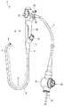
以下、図面を参照して本発明の形態を説明する。図面は本発明の一実施形態に係わり、図1に示すように、本実施形態の電子内視鏡(以下、単に内視鏡と称す)1は、細長管状に形成される挿入部2と、この挿入部2の基端に連設される操作部3と、この操作部3から延設される内視鏡ケーブルであるユニバーサルコード4と、このユニバーサルコード4の先端に配設される内視鏡コネクタ5などによって主に構成されている。(Constitution)
Hereinafter, embodiments of the present invention will be described with reference to the drawings. The drawings relate to an embodiment of the present invention. As shown in FIG. 1, an electronic endoscope (hereinafter simply referred to as an endoscope) 1 of the present embodiment includes an
挿入部2は、先端側から順に、先端部6、湾曲部7、可撓管部8が連設されて形成され可撓性を備えた管状部材である。このうち、先端部6には、内部に撮像手段を備えた図示しない撮像装置である撮像ユニット、照明手段などが収納配置されている。 The
湾曲部7は、先端側に第1の湾曲部7aと、この第1の湾曲部7aの基端に連設された第2の湾曲部7bとを備え、操作部3の操作部材のうち後述する湾曲レバー13の回動操作によって上下2方向(UP−DOWN)へと能動的に湾曲させ得るように構成される機構部位である。 The
なお、湾曲部7は、このタイプのものに限定されることはなく、上下方向に加えて左右方向をも含めた四方向(上下左右の操作によって軸回りの全周方向、UP−DOWN/RIGHT−LEFT)に湾曲し得るタイプのものであっても良い。 Note that the
可撓管部8は、受動的に可撓可能となるように柔軟性を持たせて形成される管状部材である。この可撓管部8の内部には、処置具挿通チャンネルのほか、先端部6に内蔵される撮像装置から延出し、さらに操作部3からユニバーサルコード4の内部へと延設される各種信号線、光源装置からの照明光を導光し先端部6から出射させるためのライトガイドなどが挿通している(いずれも不図示)。 The
操作部3は、先端側に設けられ可撓管部8の基端を覆って可撓管部8と接続される折れ止め部9と、この折れ止め部9に連設され使用者が内視鏡1を使用する時に手によって把持する把持部10と、この把持部10の外表面に設けられる各種内視鏡機能を操作する操作手段と、処置具挿通部11と、吸引バルブ15と、を有して構成される。 The operation unit 3 is provided on the distal end side, covers the base end of the
操作部3に設けられる操作手段としては、例えば湾曲部7の湾曲操作を行う湾曲レバー13、送気送水操作または吸引操作、撮像手段、照明手段などの各対応する操作を行うための複数の操作部材14などがある。 As the operation means provided in the operation unit 3, for example, a plurality of operations for performing respective corresponding operations such as a
処置具挿通部11は、図示しない各種の処置具を挿入する処置具挿通口を備え、操作部3の内部で、分岐部材を介して処置具挿通チャンネルに連通する構成部である。この処置具挿通部11には、処置具挿通口を開閉するための蓋部材であって、この処置具挿通部11に対して着脱自在(交換可能)に構成される鉗子栓12が配設されている。 The treatment
ユニバーサルコード4は、挿入部2の先端部6から、この挿入部2内部を挿通して操作部3に至り、さらに操作部3から延出する各種信号線などを内部に挿通すると共に、図示しない光源装置に接続されるライトガイドバンドルを挿通し、さらに送気送水装置から延出される図示しない送気送水用チューブを挿通する複合ケーブルである。 The universal cord 4 is inserted from the
内視鏡コネクタ5は、図示しない外部機器のビデオプロセッサとの間を接続する信号ケーブルが接続される電気コネクタ部16を側面部に有すると共に、外部機器である光源装置との間を接続される図示しないライトガイドバンドルおよび電気ケーブルが接続される光源コネクタ部17と、図示しない外部機器の送気送水装置からの送気送水用チューブ(不図示)を接続する送気送水プラグ(不図示)などを有して構成されている。 The
ここで、本実施の形態の内視鏡1の挿入部2に設けられた湾曲部7の構成について、図2から図5に基づき、以下に説明する。なお、以下の説明において、挿入部2の周知の構成、先端部6および可撓管部8に関しては、説明を省略する。 Here, the configuration of the
図2は、第1の湾曲部と第2の湾曲部を中心に示した斜視図であって、図3は、第1の湾曲部と第2の湾曲部を中心に示した断面図である。そして、図2と図3に示すように、湾曲部7は、先端側の第1の湾曲部7a内に先端側湾曲管である第1の湾曲管21が配設され、基端側の第2の湾曲部7b内に基端側湾曲管である第2の湾曲管22が配設されている。 FIG. 2 is a perspective view centered on the first curved portion and the second curved portion, and FIG. 3 is a cross-sectional view centered on the first curved portion and the second curved portion. . As shown in FIGS. 2 and 3, the
なお、湾曲部7は、これら第1の湾曲管21および第2の湾曲管22の周囲を覆うように、図示しない湾曲ブレードである網管、湾曲ゴムである外皮などが被覆されている。 The
第1の湾曲管21は、複数の湾曲駒25がリベットなどの枢支部26によって回動自在に連結され、挿入部2の挿入軸方向に沿って所定の長さを有して構成されている。 The
湾曲駒25は、略円管状に形成され、それぞれの両端中央部分が枢支部26によって回動自在に連結されている。そして、最先端の湾曲駒25aは、挿入部2の先端部6と連結され、最基端の湾曲駒25bが第2の湾曲管22の先端に枢支部26によって回動自在に連結されている。 The
なお、これらの複数の湾曲駒25は、それぞれ1つの湾曲駒25の内周部に複数、ここでは2つのワイヤ受け部であるワイヤガイド29が配設されている(図3参照)。これら2つのワイヤガイド29は、1つの湾曲駒25において、枢支部26によって連結される部位に対して、湾曲駒25の中心軸回りに略90度回転させた上下の位置に設けられている。 The plurality of
また、複数の湾曲駒25に設けられたそれぞれのワイヤガイド29には、操作部3に設けられた湾曲レバー13の操作によって、牽引弛緩されて進退移動する操作ワイヤ28が挿通されている。なお、最先端の湾曲駒25aには、複数、ここでは2つの操作ワイヤ28のそれぞれの先端が固定されるワイヤ固定部31が上下の位置に2つ配設されている。 The
操作ワイヤ28は、湾曲部7の基端に連設された可撓管部8及び操作部3内において、コイルチューブ35内に挿通されている。このコイルチューブ35は、先端が湾曲部7と可撓管部8との境界部分に位置するように配置され、操作ワイヤ28自体と、挿入部2内及び操作部3内の各種構成要素を保護する保護部材である。 The
第2の湾曲管22は、第1の湾曲管21の基端側に配置され、超弾性合金によって形成された湾曲要素としての円筒状の湾曲管本体を主体とした部材である。 The
ここで、第2の湾曲管22を構成する超弾性合金材としては、例えば、Ni−Ti(ニッケルチタン)、チタン合金、ベータチタン、純チタン、64チタン、A7075などが挙げられる。 Here, examples of the superelastic alloy material constituting the
第2の湾曲管22には、当該第2の湾曲管22の周方向に延在する部分円弧状の長孔を基本形状とする複数の湾曲用スリット24が、挿入部2の挿入軸方向に沿って所定の間隔に例えばレーザ加工などによって設けられている。 In the
これら複数の湾曲用スリット24は、湾曲管22の長手方向に対して直交する方向の上下の位置に互い違いに形成されている。 The plurality of bending
また、第2の湾曲管22の内周部にも、湾曲駒25と同様に、複数のワイヤガイド29が配設されている。これら複数のワイヤガイド29は、第2の湾曲管22の上下の位置において、複数の湾曲用スリット24の間に設けられている。 Further, similarly to the
そして、複数のワイヤガイド29も、複数、ここでは2つの操作ワイヤ28が第2の湾曲管22における上下の位置に挿通されている。 The plurality of wire guides 29 are also inserted into the upper and lower positions of the
(作用)
上記の構成で示したように、湾曲部7は、第1の湾曲部7aに複数の湾曲駒25が枢支部26によって回動自在に連結された駒タイプの第1の湾曲管21が先端側に配置され、第2の湾曲部7b内に駒タイプの第1の湾曲管21の基端側に管状部材である超弾性管に複数の湾曲用スリット24が形成されたスリットタイプの第2の湾曲管22が配置されている。これらの部位の動きなどを含めた作用について図4〜図7を使用して以下に説明する。(Function)
As shown in the above configuration, the bending
図4は、UP側に湾曲部を湾曲させた様子を示し、図5は、図4の湾曲部を湾曲させた状態からさらにUP方向に湾曲させた様子であり、図6は、DOWN側に湾曲部を湾曲させた様子であり、図7は、図6の湾曲部をさらにDOWN方向へと湾曲させた状態を表している。 4 shows a state where the bending portion is bent toward the UP side, FIG. 5 illustrates a state where the bending portion illustrated in FIG. 4 is further bent in the UP direction, and FIG. 6 illustrates a state where the bending portion is bent toward the DOWN side. FIG. 7 shows a state in which the bending portion of FIG. 6 is further bent in the DOWN direction.
湾曲部7は、操作部3の湾曲レバー13が所定の方向に回動操作されることによって、複数、ここでは2つ存在する操作ワイヤ28が進退すると、各操作ワイヤ28の先端側が、最先端駒25aの先端側で固定されているため、図4から図7に示すように、湾曲部7が能動的に湾曲する。 When the bending
この湾曲動作において、湾曲部7の先端側の第1の湾曲部7aは、内部に設けられた駒タイプの第1の湾曲管21によって、第2の湾曲管22が内部に設けられた基端側の第2の湾曲部7bに比べて速く曲がり、かつ、曲がりやすくなっている。 In this bending operation, the
すなわち、湾曲部7の基端側の第2の湾曲部7bは、湾曲部7の先端側の第1の湾曲部7aと異なり、内部に設けられるスリットタイプの第2の湾曲管22が超弾性体で形成されていることによって、先端側の第1の湾曲部7aに比べて曲げモーメントが強く、曲がりにくくなっている。 That is, the
そのため、湾曲部7は、基端側の第2の湾曲部7bが、先端側に比べて曲がる速さが遅くなるように構成されている。 Therefore, the bending
その結果、湾曲部7は、操作部3の湾曲レバー13が操作された初動において、図4または図6に示すように、先端側に配設された第1の湾曲部7aが先に小さな曲率半径で曲がり、次いで基端側が先端側に配設された第2の湾曲部7bが先端側の第1の湾曲部7aに比べて大きな曲率半径で曲がるように作動する。 As a result, in the initial movement of the bending
ここで、湾曲部7の第1の湾曲部7aと第2の湾曲部7bの最大湾曲角度の違いについて詳細に述べると、ここでの湾曲部7は、第1の湾曲管21を構成する複数の湾曲駒25の回動範囲の設定によって、先端側の第1の湾曲部7aの最大湾曲角度が120度程度となるように構成されている。 Here, the difference in the maximum bending angle between the
また、湾曲部7は、第2の湾曲管22を構成する超弾性管の複数の湾曲用スリット24の形成間隔の設定によって、基端側の第2の湾曲部7bの最大湾曲角度が90度程度となるように構成されている。 Further, the bending
なお、湾曲部7は、湾曲操作されたときの初動において、複数の湾曲駒25の回動によって第1の湾曲管21が先に湾曲作動して(図4または図6)、さらに湾曲操作されると、先端側の第1の湾曲部7aが第2の湾曲部7bよりも先に120度程度の最大湾曲角度まで湾曲する。 In the initial movement when the bending
そして、湾曲部7は、超弾性管に複数の湾曲用スリット24が形成された第2の湾曲管22が設けられた第2の湾曲部7bが90度程度の最大湾曲角度まで湾曲して(図5または図7)、第1の湾曲部7aと第2の湾曲部7bを総合して全体的に210度程度に最大湾曲される。 In the bending
このように、湾曲部7の先端側の第1の湾曲部7aの最大湾曲角度を120度程度とするのは、内視鏡1が気管支鏡とした場合、入り組んだ気管支の分岐角度の最大角度が120度程度であり、湾曲操作時の挿入部2の先端部6の挿入方向の方向性を決めやすく湾曲操作性を向上させると共に、気管支への挿入部2の挿入性を向上させるためである。 As described above, the maximum bending angle of the
(効果)
以上の説明により、本実施の形態の内視鏡1は、操作部3の湾曲レバー13によって湾曲操作されると、挿入部2に設けられた湾曲部7の先端側の第1の湾曲部7aが基端側の第2の湾曲部7bよりも先に湾曲始動する。(effect)
As described above, when the endoscope 1 according to the present embodiment is bent by the bending
すなわち、内視鏡1は、挿入部2を気管支などの入り組んだ体腔内に挿入する際に、湾曲部7の基端側の第2の湾曲部7bよりも先端側の第1の湾曲部7aから湾曲始動するように構成されることで、挿入部2の小回りが効くようになる。 That is, when inserting the
これにより、内視鏡1は、操作部3に設けられた湾曲レバー13の少ない操作で気管支などの入り組んだ体腔内壁の形状に湾曲部7の形を容易に合わせられるようになり、湾曲操作時における湾曲部7の湾曲調節が容易となる。そのため、内視鏡1は、湾曲部7を湾曲操作する際の操作性がより一層向上する。 Thereby, the endoscope 1 can easily adjust the shape of the bending
さらに、内視鏡1は、操作部3の湾曲レバー13がさらに操作されることで、第1の湾曲部7aが最大湾曲角である120度程度まで湾曲してから、第2の湾曲部7bが最大湾曲角である90度程度まで湾曲する。 Furthermore, the endoscope 1 is further operated by the bending
そして、湾曲部7は、第1の湾曲部7aと第2の湾曲部7bのそれぞれの最大湾曲角度を合計した210度程度に最大湾曲するようになっている。 The bending
すなわち、内視鏡1は、湾曲部7の先端側と基端側で最大湾曲したとき、先端側の第1の湾曲部7aの曲率半径が小さく、基端側の第2の湾曲部7bの曲率半径が大きくなるように構成されている。 That is, when the endoscope 1 is bent at the distal end side and the proximal end side of the bending
これにより、内視鏡1は、気管支などの入り組んだ体腔内への挿入部2の挿入性が向上すると共に、挿入部2の湾曲部7の基端側の第2の湾曲部7bが体腔壁に接触して力を加えることを防ぐことができるため、患者への違和感、苦痛などを低減することができる。 Thereby, in the endoscope 1, the insertion property of the
(変形例)
図8、図9及び図10は、第2の湾曲部7bの超弾性管に設けられた上述の湾曲用スリット24の構造を図示している。そして、図8、図9、図10では、それぞれ(第1の)湾曲用スリット24の配置または、形状についてのパターンの違いを示している。(Modification)
8, FIG. 9 and FIG. 10 illustrate the structure of the above-described bending slit 24 provided in the superelastic tube of the second bending portion 7b. 8, FIG. 9, and FIG. 10 show the difference in pattern regarding the arrangement or shape of the (first) bending
パターンの規則性としては、以下に説明する変形例から分かるように、超弾性管の長手方向に設けた複数の切欠における隣接する切欠間の間隔(ピッチ)、複数の各切欠の切欠幅が超弾性管(挿入部2)の長手方向に沿って変化する。 As can be seen from the modifications described below, the regularity of the pattern is such that the interval (pitch) between adjacent notches in the plurality of notches provided in the longitudinal direction of the superelastic tube and the notch width of each notch are excessive. It changes along the longitudinal direction of the elastic tube (insertion portion 2).
なお、図11及び図12は、挿入部2の湾曲部7の第2の湾曲部7bの基端に受動湾曲部を設けた構造を図示している。 11 and 12 illustrate a structure in which a passive bending portion is provided at the base end of the
(第1の変形例)
まずは、変形例のうち第1の変形例について述べる。
第1変形例としての図8においては、第2の湾曲管22を構成する超弾性管に設けられる湾曲用スリットのパターンが超弾性管の長手方向に一定でなく、途中で変化した構造となっている。(First modification)
First, a first modification among the modifications will be described.
In FIG. 8 as a first modified example, the pattern of the slits for bending provided in the superelastic tube constituting the
図8の図示例では、第2の湾曲部7bに設けられている第2の湾曲管22は、前側の第1の湾曲用スリット24u、24dと後側の第2の湾曲用スリット24u′、24d′とが形成されている。 In the illustrated example of FIG. 8, the
前側の第1の湾曲用スリット24u、24dが、例えば図3で示した第2の湾曲管22は、上述の湾曲用スリット24と同様に形成されており、第1の湾曲用スリット24u、24dを所定の長さ設けた位置から後方側の部分に後側の第2の湾曲用スリット24u′、24d′が適度の長さにわたって設けられている。 The
後側の第2の湾曲用スリット24u′、24d′は、第2の湾曲管22の長手方向の間隔d1a′が前側の第1の湾曲用スリット24u、24dの間隔d1aよりも大きくなるように形成されている。 The rear
このような構成とすることで、第2の湾曲部7bは、図8のような構造にすることにより、操作ワイヤ28u又は28dを牽引した場合、第1の湾曲用スリット24u、24dが形成された第2の湾曲管22における前側の部分をより大きく湾曲させることが可能となる。これに対して、第2の湾曲部7bは第2の湾曲用スリット24u‘、24d’が形成された第2の湾曲管22における後側の部分の湾曲量が抑制される。このような構成とすることで、内視鏡1は、挿入部2を大きく屈曲した体腔内への挿入がし易くなる効果を有する。 By adopting such a configuration, the
(第2の変形例)
図8では第2の湾曲管22の長手方向に設ける第2の湾曲用スリット24u′、24d′の間隔d1a′を第1の湾曲用スリット24u、24dの間隔d1aと異なるように変えていたが、図9に示す第2変形例のように後側の第2の湾曲用スリット24u′、24d′の幅(つまり切欠幅)を変更するようにしても良い。(Second modification)
In FIG. 8, the distance d1a ′ between the
図9の図示例では、後側の第2の湾曲用スリット24u′、24d′の切欠幅w2a′を前側の第1の湾曲用スリット24u、24dの切欠幅w1aよりも大きくしている。なお、後側の第2の湾曲用スリット24u′、24d′を、超弾性管の長手方向に設ける間隔も変えるようにしても良いし、変えないようにしても良い。 In the illustrated example of FIG. 9, the notch width w2a ′ of the second
本変形例の内視鏡1では、第1の湾曲用スリット24u、24d及び第2の湾曲用スリット24u‘、24d’の間隔の大きさと切欠の幅との大きさに依存して、図8に示した変形例1の場合と同様または類似の効果を有する。 In the endoscope 1 of the present modification example, depending on the size of the interval between the
(第3の変形例)
次に変形例のうち第3の変形例について述べる。
図8及び図9は、湾曲管22を構成する第2の湾曲部7bに設ける湾曲用スリットのパターンが超弾性管の長手方向に一定でなく、途中で変化する構造の場合を説明したが、図10に示すように第2の湾曲部7bを構成する第2の湾曲管に設ける湾曲用スリットのパターンが超弾性管の長手方向に一定でなく、途中で変化する構造にしても良い。(Third Modification)
Next, a third modification of the modifications will be described.
8 and 9 illustrate the case where the pattern of the slit for bending provided in the
第1の変形例及び第2の変形例においては、第2の湾曲部7b内に設けられる第2の湾曲管22に形成される第1の湾曲用スリット24uと第2の湾曲用スリット24dは、長手方向の位置がずれているのみで、実質的に同じ切欠であったが、本変形例においては、例えば上方向に湾曲させるための第1の湾曲用スリット24uの切欠幅w1cを、下方向に湾曲させるための第2の湾曲用スリット24dの切欠幅w1aよりも大きくしている。 In the first modification and the second modification, the
なお、第1の湾曲用スリット24uと第2の湾曲用スリット24dとにおける第2の湾曲管22の長手方向の間隔(ピッチ)d1u、d1dは、同じ値である。 Note that the distance (pitch) d1u and d1d in the longitudinal direction of the
このような構造にした場合、操作ワイヤ28u又は28dを牽引した場合、上方向の湾曲量を下方向の湾曲量よりも大きくできる。 In such a structure, when the
このため、大きく湾曲させる必要があるような場合には、上方向の湾曲を使用し、大きく湾曲させる必要がないような場合には、下方向の湾曲を使用するなどの使い分けができる。
なお、可撓管部8は、先に述べた実施形態と同様である。For this reason, when it is necessary to make a large curve, the upward curve is used, and when it is not necessary to make a large curve, the downward curve can be used.
The
(第4の変形例)
次に、変形例のうち、第4の変形例について述べる。
図11に示すように、本変形例の内視鏡1の挿入部2の湾曲部7は、能動的湾曲部である第1の湾曲部7a及び第2の湾曲部7bと、受動的湾曲部である第3の湾曲部7cが設けられている。(Fourth modification)
Next, of the modifications, a fourth modification will be described.
As shown in FIG. 11, the bending
具体的には、能動的湾曲部である第1の湾曲部7a内及び第2の湾曲部7b内には、上述と同様に第1の湾曲管21と、超弾性管から構成された第2の湾曲管22が設けられており、さらに第3の湾曲部7c内にも超弾性管から構成された第3の湾曲管23が設けられている。すなわち、ここでの挿入部2は、第2の湾曲管22が設けられる第2の湾曲部7bの後端から長手方向に所定の長さにわたって、これまでの実施の形態では有しない受動的湾曲部である第3の湾曲部7cを備え、さらに、第3の湾曲部7cの基端側に、可撓管部8が備わっている。 Specifically, in the
そして、第2の湾曲部7b、第3の湾曲部7c及び可撓管部8は、内部に超弾性管によって、一体的に形成された第2の湾曲管22と第3の湾曲管23と螺旋状管39が設けられている。 And the
受動的湾曲部である第3の湾曲部7cに設けられる第3の湾曲管23は、長手方向に沿って、受動的湾曲用スリット27u、27dが上下対称に形成されている。 In the
また、受動的湾曲用スリット27u、27dは、第3の湾曲管23の円管面の周方向の長さの半分よりも若干短い長さで形成されている。 The
さらに、第3の湾曲管23には、受動的湾曲用スリット27cが、左右方向に湾曲可能となる周方向に左右対称に設けられている。 Further, the
このように、第3の湾曲部7cは、第3の湾曲管23に形成された受動的湾曲用スリット27u、27d、27cにより上下左右方向に屈曲(湾曲)し易い構造にしている。
そして、受動的湾曲部7cの後ろ側に連設された可撓管部8には、超弾性管に螺旋状のスリット38が形成された螺旋状管39が配設されている。In this manner, the
A
(第5の変形例)
図12は、受動的湾曲部である第3の湾曲部7cに設けられた第3の湾曲管23に形成される受動的湾曲用スリットの構造の変形例を示す。すなわち、本変形例では、第4の変形例に記載した受動的湾曲部を構成する第3の湾曲部7cの第3の湾曲管23に設ける受動的湾曲用スリット27u、27d、27cの構造を変更している。
本変形例における受動的湾曲用スリットは、第3の湾曲管23の円筒面において、長手方向に螺旋に沿って形成された受動的湾曲用スリット27u、27d、27cにより構成されている。すなわち、本変形例においては、螺旋に沿って離散的に受動的湾曲用スリット27u、27d,27cが周期的に形成されている。(Fifth modification)
FIG. 12 shows a modification of the structure of the passive bending slit formed in the
The passive bending slit in the present modification is configured by
図12では螺旋のピッチがd2の例で示している。また、図12に示す例では、第2の湾曲部7bが湾曲可能となる湾曲方向(上下方向)に沿って受動的湾曲用スリット27u、27d、27cを周期的に形成して、当該方向へ湾曲(屈曲)し易くすると共に、更に他の方向にも湾曲(屈曲)し易いように受動的湾曲用スリット27u、27d、27cを周期的に形成している。 FIG. 12 shows an example in which the spiral pitch is d2. In the example shown in FIG. 12, the
また、ここでも、受動的湾曲部7cの後ろ側に連設された可撓管部8には、超弾性管に螺旋状のスリット38が形成された螺旋状管39が配設されている。 Also in this case, a
なお、図12は、図11における受動的湾曲部7cを変形した構成であるが、図8、図9及び図10におけるいずれかの変形例にそれらの構成を適用しても良い。12 shows a configuration in which the
さらに、本実施形態の中では、湾曲部7において、能動的湾曲部としての第1の湾曲部7aと第2の湾曲部7bの湾曲方向は、上下(UP,DOWN)方向について示したが、これに限定されることなく、左右(LEFT−RIGHT)を含む4方向に湾曲するようにしてもよい。 Furthermore, in the present embodiment, the bending direction of the
なお、上述の実施の形態に記載した発明は、その実施の形態に限ることなく、その他、実施段階ではその要旨を逸脱しない範囲で種々の変形を実施し得ることが可能である。 The invention described in the above-described embodiment is not limited to the embodiment, and various modifications can be made without departing from the scope of the invention in the implementation stage.
本出願は、2014年9月22日に日本国に出願された特願2014−192920号を優先権主張の基礎として出願するものであり、上記の内容は、本願明細書、請求の範囲、および図面に引用されたものである。 This application is filed on the basis of the priority claim of Japanese Patent Application No. 2014-192920 filed in Japan on September 22, 2014, and the above contents include the present specification, claims, and It is cited in the drawing.
Claims (7)
Translated fromJapanese前記先端側湾曲管の基端側に連結され、所定の湾曲角を得るための曲げモーメントが前記先端側湾曲管よりも大きい湾曲要素を備えた基端側湾曲管と、
前記先端側湾曲管と前記基端側湾曲管とを被覆する外皮と、
前記先端側湾曲管の最先端の前記湾曲駒に配設したワイヤ固定部に先端が固定され、牽引弛緩によって前記先端側湾曲管及び前記基端側湾曲管を能動的に湾曲させる操作ワイヤと、
前記操作ワイヤが挿通されるワイヤ受け部と、
を備えることを特徴とする内視鏡用湾曲部。A distal end side bending tube in which a plurality of bending pieces are connected continuously and freely rotatable;
A proximal-side bending tube that is connected to the proximal-side of the distal-side bending tube and includes a bending element having a bending moment larger than that of the distal-side bending tube to obtain a predetermined bending angle;
An outer skin covering the distal end side bending tube and the proximal end side bending tube;
An operation wire having a distal end fixed to a wire fixing portion disposed on the most distal bending piece of the distal end side bending tube, and actively bending the distal end side bending tube and the proximal end side bending tube by pulling and loosening;
A wire receiving portion intowhich the operation wire is inserted,
Endoscope bendingportion, wherein theobtaining Bei a.
Applications Claiming Priority (3)
| Application Number | Priority Date | Filing Date | Title |
|---|---|---|---|
| JP2014192920 | 2014-09-22 | ||
| JP2014192920 | 2014-09-22 | ||
| PCT/JP2015/071319WO2016047265A1 (en) | 2014-09-22 | 2015-07-28 | Bending tube for endoscope, and endoscope provided with said bending tube for endoscope |
Publications (2)
| Publication Number | Publication Date |
|---|---|
| JP5993535B2true JP5993535B2 (en) | 2016-09-14 |
| JPWO2016047265A1 JPWO2016047265A1 (en) | 2017-04-27 |
Family
ID=55580798
Family Applications (1)
| Application Number | Title | Priority Date | Filing Date |
|---|---|---|---|
| JP2016522823AActiveJP5993535B2 (en) | 2014-09-22 | 2015-07-28 | Endoscope bending portion and endoscope provided with the endoscope bending portion |
Country Status (3)
| Country | Link |
|---|---|
| US (1) | US10149608B2 (en) |
| JP (1) | JP5993535B2 (en) |
| WO (1) | WO2016047265A1 (en) |
Families Citing this family (21)
| Publication number | Priority date | Publication date | Assignee | Title |
|---|---|---|---|---|
| US12220538B2 (en) | 2008-12-08 | 2025-02-11 | Scientia Vascular, Inc. | Micro-fabricated intravascular devices having varying diameters |
| EP3207853A4 (en)* | 2015-06-08 | 2018-06-13 | Olympus Corporation | Endoscope |
| CN107582015A (en)* | 2016-07-08 | 2018-01-16 | 深圳市先赞科技有限公司 | It is a kind of using equidistant spring and the endoscope plug-in package of support component |
| US11207502B2 (en) | 2016-07-18 | 2021-12-28 | Scientia Vascular, Llc | Guidewire devices having shapeable tips and bypass cuts |
| WO2018172565A1 (en) | 2017-03-24 | 2018-09-27 | Ambu A/S | Articulated tip part for an endoscope |
| ES2966345T3 (en) | 2017-05-26 | 2024-04-22 | Scientia Vascular Inc | Microfabricated medical device with a non-helical cutting arrangement |
| CN108553070B (en)* | 2018-05-17 | 2020-09-18 | 黄琴 | Controllable bent pipe structure |
| WO2020039526A1 (en)* | 2018-08-22 | 2020-02-27 | オリンパス株式会社 | Endoscope |
| WO2020154314A1 (en)* | 2019-01-21 | 2020-07-30 | Transit Scientific, LLC | Hypotube catheters |
| EP3934507A4 (en)* | 2019-03-04 | 2022-11-09 | Georgia Tech Research Corporation | STEERING AND FLEXIBLE ROBOTIC ENDOSCOPIC TOOLS FOR MINIMALLY INVASIVE PROCEDURES |
| WO2021028883A1 (en)* | 2019-08-15 | 2021-02-18 | Auris Health, Inc. | Medical device having multiple bending sections |
| EP4017334A1 (en)* | 2019-08-22 | 2022-06-29 | Boston Scientific Scimed, Inc. | Disposable endoscopic device |
| US12343485B2 (en) | 2020-01-23 | 2025-07-01 | Scientia Vascular, Inc. | High torque guidewire device |
| US12178975B2 (en) | 2020-01-23 | 2024-12-31 | Scientia Vascular, Inc. | Guidewire having enlarged, micro-fabricated distal section |
| WO2021229792A1 (en)* | 2020-05-15 | 2021-11-18 | オリンパス株式会社 | Endoscope apparatus and bending member for endoscope |
| CN114305295A (en)* | 2020-09-28 | 2022-04-12 | 微创优通医疗科技(嘉兴)有限公司 | Endoscope and endoscope system |
| US12296112B2 (en) | 2020-10-05 | 2025-05-13 | Scientia Vascular, Inc. | Microfabricated catheter devices with high axial strength |
| CN112472004A (en)* | 2020-12-16 | 2021-03-12 | 杭州思康新医疗科技有限公司 | Endoscope and insertion part for endoscope |
| DE102021113183A1 (en)* | 2021-05-20 | 2022-11-24 | Ambu A/S | Endoscope with a bending section with a varying length of joints |
| CN116250793B (en)* | 2023-02-23 | 2025-09-16 | 浙江华诺康科技有限公司 | Snake bone tube and endoscope |
| CN116421127A (en)* | 2023-03-01 | 2023-07-14 | 浙江优亿医疗器械股份有限公司 | Endoscope and snake bone structure thereof |
Family Cites Families (11)
| Publication number | Priority date | Publication date | Assignee | Title |
|---|---|---|---|---|
| US4911148A (en)* | 1989-03-14 | 1990-03-27 | Intramed Laboratories, Inc. | Deflectable-end endoscope with detachable flexible shaft assembly |
| US6749560B1 (en)* | 1999-10-26 | 2004-06-15 | Circon Corporation | Endoscope shaft with slotted tube |
| JP2005230135A (en)* | 2004-02-18 | 2005-09-02 | Pentax Corp | Endoscope flexible tube |
| JP2006068393A (en)* | 2004-09-03 | 2006-03-16 | Olympus Corp | Endoscope |
| US8206287B2 (en) | 2005-02-14 | 2012-06-26 | Olympus Corporation | Endoscope having flexible tube |
| JP4323441B2 (en) | 2005-02-14 | 2009-09-02 | オリンパス株式会社 | Endoscope |
| US9254123B2 (en)* | 2009-04-29 | 2016-02-09 | Hansen Medical, Inc. | Flexible and steerable elongate instruments with shape control and support elements |
| WO2011092937A1 (en)* | 2010-01-29 | 2011-08-04 | オリンパスメディカルシステムズ株式会社 | Inserting apparatus and endoscope |
| JP5371822B2 (en)* | 2010-02-15 | 2013-12-18 | オリンパス株式会社 | Endoscope |
| GB2483735A (en)* | 2010-09-19 | 2012-03-21 | Vital View Ltd Il Il | A sealed and bendable catheter |
| CN103764012B (en) | 2012-06-22 | 2016-03-09 | 奥林巴斯株式会社 | Curved tubes, medical equipment |
- 2015
- 2015-07-28JPJP2016522823Apatent/JP5993535B2/enactiveActive
- 2015-07-28WOPCT/JP2015/071319patent/WO2016047265A1/enactiveApplication Filing
- 2016
- 2016-11-18USUS15/355,138patent/US10149608B2/enactiveActive
Also Published As
| Publication number | Publication date |
|---|---|
| US10149608B2 (en) | 2018-12-11 |
| WO2016047265A1 (en) | 2016-03-31 |
| US20170065153A1 (en) | 2017-03-09 |
| JPWO2016047265A1 (en) | 2017-04-27 |
Similar Documents
| Publication | Publication Date | Title |
|---|---|---|
| JP5993535B2 (en) | Endoscope bending portion and endoscope provided with the endoscope bending portion | |
| JP5981080B1 (en) | Endoscope bending tube and endoscope provided with the endoscope bending tube | |
| JP5908192B2 (en) | Endoscope | |
| JP6010267B1 (en) | Endoscope insertion part and endoscope | |
| CN104540437B (en) | sinus endoscopy | |
| JP5711434B1 (en) | Endoscope | |
| JP6043027B2 (en) | Endoscope | |
| JP6180679B2 (en) | Endoscope | |
| JP5671360B2 (en) | Endoscope external channel | |
| US10758117B2 (en) | Endoscopic assistance devices and methods of use | |
| WO2005009229A1 (en) | Endoscope | |
| JP6697291B2 (en) | Endoscope bending tube | |
| WO2016035393A1 (en) | Endoscope | |
| JP6257854B2 (en) | Endoscope | |
| JP6062118B2 (en) | Auxiliary tool and endoscope system | |
| CN113939218B (en) | Medical probe with improved maneuverability | |
| JP2010017401A (en) | Endoscope and method of manufacturing endoscope bending section | |
| JPWO2015174128A1 (en) | Endoscope | |
| WO2016199478A1 (en) | Endoscope | |
| JP2018175225A (en) | Endoscope system | |
| US20130178703A1 (en) | Endoscope Shaft With Malleable Section | |
| WO2016056416A1 (en) | Endoscope | |
| JPWO2018116557A1 (en) | Curved tube structure and endoscope |
Legal Events
| Date | Code | Title | Description |
|---|---|---|---|
| A521 | Request for written amendment filed | Free format text:JAPANESE INTERMEDIATE CODE: A523 Effective date:20160413 | |
| A621 | Written request for application examination | Free format text:JAPANESE INTERMEDIATE CODE: A621 Effective date:20160413 | |
| A871 | Explanation of circumstances concerning accelerated examination | Free format text:JAPANESE INTERMEDIATE CODE: A871 Effective date:20160413 | |
| TRDD | Decision of grant or rejection written | ||
| A975 | Report on accelerated examination | Free format text:JAPANESE INTERMEDIATE CODE: A971005 Effective date:20160728 | |
| A01 | Written decision to grant a patent or to grant a registration (utility model) | Free format text:JAPANESE INTERMEDIATE CODE: A01 Effective date:20160802 | |
| A61 | First payment of annual fees (during grant procedure) | Free format text:JAPANESE INTERMEDIATE CODE: A61 Effective date:20160819 | |
| R151 | Written notification of patent or utility model registration | Ref document number:5993535 Country of ref document:JP Free format text:JAPANESE INTERMEDIATE CODE: R151 | |
| R250 | Receipt of annual fees | Free format text:JAPANESE INTERMEDIATE CODE: R250 | |
| R250 | Receipt of annual fees | Free format text:JAPANESE INTERMEDIATE CODE: R250 | |
| R250 | Receipt of annual fees | Free format text:JAPANESE INTERMEDIATE CODE: R250 | |
| R250 | Receipt of annual fees | Free format text:JAPANESE INTERMEDIATE CODE: R250 | |
| R250 | Receipt of annual fees | Free format text:JAPANESE INTERMEDIATE CODE: R250 | |
| R250 | Receipt of annual fees | Free format text:JAPANESE INTERMEDIATE CODE: R250 | |
| R250 | Receipt of annual fees | Free format text:JAPANESE INTERMEDIATE CODE: R250 |