JP5993282B2 - System for purging a gas fuel circuit for a gas turbine engine - Google Patents
System for purging a gas fuel circuit for a gas turbine engineDownload PDFInfo
- Publication number
- JP5993282B2 JP5993282B2JP2012244035AJP2012244035AJP5993282B2JP 5993282 B2JP5993282 B2JP 5993282B2JP 2012244035 AJP2012244035 AJP 2012244035AJP 2012244035 AJP2012244035 AJP 2012244035AJP 5993282 B2JP5993282 B2JP 5993282B2
- Authority
- JP
- Japan
- Prior art keywords
- purge
- steam
- circuit
- air
- gas fuel
- Prior art date
- Legal status (The legal status is an assumption and is not a legal conclusion. Google has not performed a legal analysis and makes no representation as to the accuracy of the status listed.)
- Active
Links
Images


Classifications
- F—MECHANICAL ENGINEERING; LIGHTING; HEATING; WEAPONS; BLASTING
- F02—COMBUSTION ENGINES; HOT-GAS OR COMBUSTION-PRODUCT ENGINE PLANTS
- F02C—GAS-TURBINE PLANTS; AIR INTAKES FOR JET-PROPULSION PLANTS; CONTROLLING FUEL SUPPLY IN AIR-BREATHING JET-PROPULSION PLANTS
- F02C3/00—Gas-turbine plants characterised by the use of combustion products as the working fluid
- F02C3/20—Gas-turbine plants characterised by the use of combustion products as the working fluid using a special fuel, oxidant, or dilution fluid to generate the combustion products
- F02C3/22—Gas-turbine plants characterised by the use of combustion products as the working fluid using a special fuel, oxidant, or dilution fluid to generate the combustion products the fuel or oxidant being gaseous at standard temperature and pressure
- F—MECHANICAL ENGINEERING; LIGHTING; HEATING; WEAPONS; BLASTING
- F02—COMBUSTION ENGINES; HOT-GAS OR COMBUSTION-PRODUCT ENGINE PLANTS
- F02C—GAS-TURBINE PLANTS; AIR INTAKES FOR JET-PROPULSION PLANTS; CONTROLLING FUEL SUPPLY IN AIR-BREATHING JET-PROPULSION PLANTS
- F02C7/00—Features, components parts, details or accessories, not provided for in, or of interest apart form groups F02C1/00 - F02C6/00; Air intakes for jet-propulsion plants
- F02C7/22—Fuel supply systems
- F02C7/232—Fuel valves; Draining valves or systems
Landscapes
- Engineering & Computer Science (AREA)
- Chemical & Material Sciences (AREA)
- Combustion & Propulsion (AREA)
- Mechanical Engineering (AREA)
- General Engineering & Computer Science (AREA)
- Engine Equipment That Uses Special Cycles (AREA)
Description
Translated fromJapanese本明細書で開示される主題は、多重燃料システムを備えるガスタービンエンジンに関する。 The subject matter disclosed herein relates to a gas turbine engine comprising a multiple fuel system.
一般に、ガスタービンエンジンは、圧縮空気と燃料との混合物を燃焼させて高温の燃焼ガスを発生させる。特定のガスタービンエンジンは、例えばガス燃料と液体燃料の両方を使用する多重燃料システムを含み、多重燃料システムは一方の燃料から他方の燃料へと移行することを可能にする。一方の燃料(例えば、第1の燃料)から他方の燃料(例えば、第2の燃料)への移行中、第1の燃料の使用は停止される。しかし、第1の燃料での運転中、コーキング、第1の燃料の配管系への燃焼生成物の逆流、および、エンジンハードウェアの急速な劣化が起こる可能性がある。 In general, a gas turbine engine burns a mixture of compressed air and fuel to generate hot combustion gases. Certain gas turbine engines include, for example, multiple fuel systems that use both gas and liquid fuels, which allow a transition from one fuel to the other. During the transition from one fuel (eg, the first fuel) to the other fuel (eg, the second fuel), the use of the first fuel is stopped. However, during operation with the first fuel, coking, backflow of combustion products into the first fuel piping system, and rapid degradation of engine hardware can occur.
出願時に請求された発明の範囲に一致する特定の実施形態を以下で概説する。これらの特定の実施形態は特許請求されている発明の範囲を限定するものではなく、むしろ、これらの実施形態は本発明の可能な形態の簡単な概説を提供することのみを意図される。実際には、本発明は、以下に記載される実施形態に類似してもよいまたは以下に記載される実施形態と異なってもよい種々の形態を包含することができる。 Specific embodiments consistent with the scope of the invention claimed at the time of filing are outlined below. These particular embodiments are not intended to limit the scope of the claimed invention, but rather, these embodiments are only intended to provide a brief overview of possible forms of the invention. Indeed, the invention may encompass a variety of forms that may be similar to or different from the embodiments set forth below.
第1の実施形態によると、システムが、液体燃料システムおよびガス燃焼システムの両方で運転されるように構成された多重燃料ガスタービンを含み、多重燃料ガスタービンは、圧縮器、燃焼器およびタービンを備える。このシステムはまた、液体燃料によるガスタービンの運転中にガス燃料システムのガス燃料回路をパージするように構成されたガス燃料パージシステムを含み、ガス燃料パージシステムは、空気および蒸気でガス燃料回路を順次パージするように構成される。 According to a first embodiment, a system includes a multi-fuel gas turbine configured to operate with both a liquid fuel system and a gas combustion system, the multi-fuel gas turbine comprising a compressor, a combustor, and a turbine. Prepare. The system also includes a gas fuel purge system configured to purge the gas fuel circuit of the gas fuel system during operation of the gas turbine with liquid fuel, the gas fuel purge system including the gas fuel circuit with air and steam. It is configured to purge sequentially.
第2の実施形態によると、システムが、液体燃料による多重燃料ガスタービンの運転中に、多重燃料ガスタービンに連結されたガス燃料回路をパージするように構成されたデュアルエアースチームパージシステム(dual air and steam purge system)を含む。デュアルエアースチームパージシステムは、空気でガス燃料回路をパージするように構成された空気パージ回路と、蒸気でガス燃料回路をパージするように構成された蒸気パージ回路とを備える。 According to a second embodiment, a dual air steam purge system (dual air) configured to purge a gas fuel circuit coupled to a multi-fuel gas turbine during operation of the multi-fuel gas turbine with liquid fuel. and steam purge system). The dual air steam purge system includes an air purge circuit configured to purge the gas fuel circuit with air and a steam purge circuit configured to purge the gas fuel circuit with steam.
第3の実施形態によると、多重燃料ガスタービンのガス燃料回路をパージするための方法が、液体燃料で多重燃料ガスタービンの運転を開始することを含む。この方法はまた、最初に空気でガス燃料回路をパージすることを含む。この方法は、蒸気パラメータが蒸気注入許容閾値(steam injection permissive threshold)を満たすか否かを判定するために、蒸気供給部の蒸気パラメータを監視することを含む。この方法は、その後、蒸気パラメータが蒸気注入許容閾値を満たしたとき蒸気でガス燃料回路をパージすることをさらに含む。 According to a third embodiment, a method for purging a gas fuel circuit of a multi-fuel gas turbine includes initiating operation of the multi-fuel gas turbine with liquid fuel. The method also includes first purging the gas fuel circuit with air. The method includes monitoring the steam parameter of the steam supply to determine whether the steam parameter meets a steam injection permissive threshold. The method then further includes purging the gas fuel circuit with steam when the steam parameters meet a steam injection tolerance threshold.
複数の図面を通して同様の参照符号が同様の部品を表している添付図面を参照しながら以下の詳細な説明を読むことにより、本発明のこれらのおよび別の特徴、態様および利点がより良く理解される。 These and other features, aspects and advantages of the present invention will become better understood when the following detailed description is read with reference to the accompanying drawings in which like reference characters represent like parts throughout the several views. The
本発明の1つまたは複数の特定の実施形態を以下で説明する。これらの実施形態を簡潔に説明するために、本明細書では、実際の実装形態のすべての特徴が説明されない可能性がある。任意の工学プロジェクトまたは設計プロジェクトの場合のように、任意のこのような実際の実装形態を開発する際、システム関連の制約および事業関連の制約に対するコンプライアンスなどの、実装形態ごとに変化する可能性がある開発者特有の目標を達成するために多くの実装形態固有の決定がなされなれければならないことを認識されたい。さらに、このような開発努力は複雑で時間を要する可能性があるが、本開示の利益を享受する当業者にとっては、設計、製作および製造の通常の仕事であることを認識されたい。 One or more specific embodiments of the present invention are described below. In an effort to provide a concise description of these embodiments, all features of an actual implementation may not be described herein. When developing any such actual implementation, as in any engineering or design project, it can vary from implementation to implementation, including compliance with system-related constraints and business-related constraints. It should be recognized that many implementation specific decisions must be made to achieve certain developer specific goals. Further, while such development efforts can be complex and time consuming, it should be recognized that those of ordinary skill in the art having the benefit of this disclosure will be the normal task of design, fabrication and manufacture.
本発明の種々の実施形態の要素を導入する際、「a」、「an」、「the」の冠詞、および「上記(said)」は、その要素が1つまたは複数存在することを意味することを意図される。「comprising(備える、含む)」、「including(含む)」および「having(有する)」という単語は包括的であることを意図され、列記される要素とは異なる追加の要素が存在してもよいことを意味する。 In introducing elements of various embodiments of the present invention, the articles “a”, “an”, “the”, and “said” mean that one or more of the elements are present. Intended to be. The words “comprising”, “including” and “having” are intended to be inclusive and there may be additional elements different from the listed elements. Means that.
本開示は、液体燃料による運転中に、多重燃料システム(例えば、液体燃料およびガス燃料)および蒸気注入システムを備えるガスタービンのガス燃料回路をパージするためのシステムおよび方法に関連する。多重燃料システムを備えるガスタービンエンジンでは、液体燃料によるガスタービンエンジンの運転中に、コーキング、ガス燃料ラインおよび燃料ノズルへの燃焼性生物の逆流、ならびに、エンジンハードウェアの迅速な劣化を回避するために、ガス燃料回路(例えば、ガス燃料ライン、燃料ノズルおよびガスマニホルド)がパージされ得る。さらに、この多重燃料ガスタービンエンジンは、多重燃料ガスタービンエンジンのパワー出力を増大させるために蒸気が提供され得る。本開示の実施形態は、液体燃料によるガスタービンの運転中にガス燃料システムのガス燃料回路をパージするように構成されたガス燃料パージシステム(例えば、デュアルエアースチームパージシステム)を含むシステムを提供する。具体的には、ガス燃料パージシステムは、空気および蒸気でガス燃料回路を順次パージするように構成される。例えば、このガス燃料パージシステムは、蒸気注入許容閾値を満たす前に、最初に、空気でガス燃料システムのガス燃料回路をパージするように(例えば、蒸気が特定の温度および圧力に達する前に、ボイラが温められる)、さらに、その後、蒸気注入許容閾値を満たしたとき蒸気でガス燃料回路をパージするように構成された(同時に、多重燃料ガスタービンエンジンのパワー出力を増大させるためにガスタービンエンジンに蒸気を供給する)。このガス燃料システムは、空気でガス燃料回路をパージするための空気パージ回路と、蒸気でガス燃料回路をパージするための蒸気パージ回路とを含むことができる。特定の実施形態では、空気パージ回路および蒸気パージ回路は平行であるか、または、共通のパージ回路へと収束するように部分的に独立の回路であってもよい。例えば、ガス燃料パージ回路は、蒸気供給部からのラインに接合される第1のポートと、ガスタービンエンジンの圧縮器の圧縮器排出ポートからのラインに接合される第2のポートと、空気パージ回路に接合される第3のポートとを含むスリーウェイバルブを含むことができる。このスリーウェイバルブは、ガス燃料回路をパージするのに空気または蒸気のいずれかを使用することを可能にするために組み合わせのポートを開くように構成される。別の実施形態では、空気パージ回路および蒸気パージ回路は完全に独立の回路である。このガスタービンシステムはまた、ガス燃料パージシステムと、空気および蒸気でガス燃料回路を順次パージすることとを制御するように(例えば、パージ制御論理を介して)構成された制御装置(例えば、タービン燃料制御装置)を含むことができる。これらのシステムは、ガス燃料システムからのガス燃料を空気および蒸気により二重でパージすることを可能にするように設計され、同時に、多重燃料ガスタービンエンジンのパワー出力を増大させるために蒸気を使用することを可能にするように設計される。 The present disclosure relates to systems and methods for purging a gas fuel circuit of a gas turbine comprising a multiple fuel system (eg, liquid fuel and gas fuel) and a steam injection system during operation with liquid fuel. In gas turbine engines with multiple fuel systems, to avoid coking, backflow of combustible organisms into gas fuel lines and fuel nozzles, and rapid deterioration of engine hardware during operation of liquid turbine gas turbine engines In addition, gas fuel circuits (eg, gas fuel lines, fuel nozzles and gas manifolds) may be purged. In addition, the multi-fuel gas turbine engine may be provided with steam to increase the power output of the multi-fuel gas turbine engine. Embodiments of the present disclosure provide a system that includes a gas fuel purge system (eg, a dual air steam purge system) configured to purge the gas fuel circuit of the gas fuel system during operation of the gas turbine with liquid fuel. . Specifically, the gas fuel purge system is configured to sequentially purge the gas fuel circuit with air and steam. For example, the gas fuel purge system may first purge the gas fuel circuit of the gas fuel system with air (e.g., before the steam reaches a certain temperature and pressure) before meeting the vapor injection tolerance threshold. The gas turbine engine is configured to purge the gas fuel circuit with steam when the steam injection tolerance threshold is met (at the same time, simultaneously increasing the power output of the multi-fuel gas turbine engine). To supply steam). The gas fuel system may include an air purge circuit for purging the gas fuel circuit with air and a steam purge circuit for purging the gas fuel circuit with steam. In certain embodiments, the air purge circuit and the steam purge circuit may be parallel or may be partially independent circuits to converge to a common purge circuit. For example, the gas fuel purge circuit includes a first port joined to the line from the steam supply, a second port joined to the line from the compressor discharge port of the compressor of the gas turbine engine, and an air purge. A three-way valve including a third port joined to the circuit may be included. The three-way valve is configured to open a combination port to allow either air or steam to be used to purge the gas fuel circuit. In another embodiment, the air purge circuit and the steam purge circuit are completely independent circuits. The gas turbine system also includes a controller (eg, a turbine) configured to control the gas fuel purge system and sequentially purge the gas fuel circuit with air and steam (eg, via purge control logic). A fuel control device). These systems are designed to allow the gas fuel from the gas fuel system to be dual purged with air and steam, while at the same time using steam to increase the power output of a multi-fuel gas turbine engine Designed to allow you to do.
図1は、デュアルエアースチームパージシステム16(例えば、ガス燃料パージシステム)を有するタービンシステム12(例えば、ガスタービンエンジン14)のための燃料管理システム10の一実施形態の概略的なブロック図である。以下で詳細に説明するように、開示されるデュアルエアースチームパージシステム16は、液体燃料によるガスタービンエンジン14の運転中にガス燃料システムのガス燃料回路(例えば、ガス燃料ライン、燃料ノズルおよびガスマニホルド)を順次パージするように構成され、また同時に、エンジン14のパワー出力を増大させるためにガスタービンエンジン14に蒸気を供給するように構成される。以下の開示は、液体燃料によるガスタービンエンジン14の運転中にガス燃料システムのガス燃料回路をパージすることを考察するが、特定の実施形態では、パージシステム16は、ガス燃料によるガスタービンエンジン14の運転中に液体燃料システムからの液体燃料をパージするのに使用され得る。さらに、別の実施形態では、パージシステム16は、同じタイプの異なる燃料(例えば、ガス燃料または液体燃料)を用いた燃料運転中に燃料システムの燃料回路(例えば、ガス燃料回路または液体燃料回路)をパージするのに使用され得る。燃料管理システム16は、ガスタービンエンジン14に燃料を供給するのを制御するように、具体的には一方の燃料の供給を終了して他方の燃料を供給するように移行するのを制御するように構成された燃料制御装置18(例えば、タービン燃料制御装置)を利用する。さらに、後でより詳細に説明するように、燃料制御装置18は、デュアルエアースチームパージシステム16を制御するように、具体的には、燃焼器からの可燃性流体がガス燃料回路へと戻るように再循環されるのを防止するためにガス燃料回路内で流体(たとえば、空気または蒸気)が継続して流れるのを維持するために空気または蒸気でガス燃料回路を順次パージすることを制御するように、構成される。タービンシステム12は、ガスタービンエンジン14(例えば、多重燃料ガスタービン)に供給するのに液体燃料および/またはガス燃料などの複数の燃料を使用することができる。特定の実施形態では、タービンシステム12は別法として液体燃料およびガス燃料を使用してもよい。別の実施液体では、タービンシステム12は別法として異なる複数のガス燃料を使用することができる。別の実施形態では、タービンシステム12は複数の異なる液体燃料を使用することができる。液体燃料には、蒸留油、軽質原油、バイオ液体燃料、および、別の液体燃料が含まれてもよい。ガス燃料には、水素ガスを含んでいても含んでいなくてもよい、工業プロセスの副生成物として作られる天然ガスおよび/または可燃性ガス(複数可)が含まれてもよい。これらの可燃性ガスは、シンガス(syngas)、合成ガス、合成天然ガス、製油所オフガス、精製所の煙道ガス(refinery flue gas)、高炉ガス、コークス炉ガス、または、別の可燃性ガスと呼ばれることがあり、また、それらを含むことができる。 FIG. 1 is a schematic block diagram of one embodiment of a
タービンシステム12(例えば、ガスタービンエンジン14)内で描かれているように、1つまたは複数の燃料ノズル20、22(例えば、一次燃料ノズル20および二次燃料ノズル22)が、供給燃料(例えば、ガス燃料および/または液体燃料)を取り込み、その燃料を空気に混合し、最適な燃焼、最適な排気、最適な燃焼消費および最適なパワー出力のための好適な比でその空気と燃料との混合物を燃焼器24内に分配する。特定の実施形態では、燃焼器24は、1つまたは複数の一次燃料ノズル20および1つまたは複数の二次燃料ノズル22を含む。空気と燃料との混合物は燃焼器24内のチャンバ内で燃焼されて高温の圧縮排ガスを生成する。燃焼器24はタービン30を通って排気出口に向かうように排ガスを誘導する。排ガスがタービン30を通過するとき、排ガスがブレードを押し込み、それによりシャフト32がタービンシステム12の軸に沿って回転する。示されるように、シャフト32は、圧縮器34を含めてタービンシステム12の種々の構成要素に接続されてもよい。圧縮器34はまた、シャフト32に連結されるブレードを含む。シャフト32が回転すると、圧縮器34内のブレードも回転し、それにより、圧縮器34を通る空気取込口からの空気が圧縮されて燃料ノズル20、22および/または燃焼器24に入る。シャフト32はまた、例えば、電力プラント内の発電機35などの負荷に接続されてもよい。この負荷には、タービンシステム12の回転による機械的な動力出力(rotational mechanical power output)によって動力供給され得る任意の適当なデバイスが含まれてもよい。後でより詳細に説明するように、圧縮器34は、タービンシステム12のパワー出力を増大させるために蒸気供給部から蒸気を受け取るように構成された圧縮器排出ポートを含むことができる。さらに、液体燃料によるガスタービンエンジン14の運転中にガス燃料システムのガス燃料回路をパージするために、圧縮器34の圧縮器排出ポートから空気が抽出され得る。 As depicted in turbine system 12 (eg, gas turbine engine 14), one or
燃料管理システム10は、ガス燃料36および液体燃料38の両方の流れをタービンシステム12(例えば、ガスタービンエンジン14)に提供する。示されるように、燃料36および38の各供給部は主燃料ライン40および42をそれぞれ含む。特定の実施形態では、燃料ライン40、42の数は多様であってもよい(例えば、2個から28個の燃料ライン)。 The
また、燃料管理システム10は、液体燃料によるガスタービンエンジン14の運転中にガス燃料ライン40(例えば、ガス燃料回路)をパージするように構成されたデュアルエアースチームパージシステム16(例えば、ガス燃料パージシステム)を含む。パージシステム16は、燃料ノズル20、22(および、ガスマニホルド)の上流にあるガス燃料ライン40に連結される1つまたは複数のパージラインまたはパージ回路48を含む。パージシステム16は、蒸気供給部50および空気供給部52の両方に連結される。蒸気供給部50は、ボイラ、熱回収ボイラ(heat recovery steam generator(HRSG))、または、別の供給源によって形成されてもよい。空気供給部52は、圧縮器34または独立の圧縮器の圧縮器排出ポートから抽出され得る。パージシステム16は、空気および蒸気で、ガス燃料システムのガス燃料回路(例えば、ガス燃料ライン40、燃料ノズル20、22、および、ガスマニホルド)を順次パージするように構成される。パージシステム16は少なくとも2つの異なる形態で運転されるように構成される。第1の形態の運転では、蒸気が注入される前の、液体燃料38を使用してエンジンが始動される間に(例えば、ボイラが温められる間)、パージシステム16は、後でより詳細に説明するように最初にガス燃料システムのガス燃料回路をパージするために、圧縮器34の圧縮器排出ポートから抽出される空気を使用する。パージシステム16は、蒸気パラメータ(例えば、温度および圧力)を蒸気注入許容閾値を満たす前に第1の形態で運転される(例えば、ボイラが温められる間)。蒸気注入許容閾値は温度と圧力の関数である。温度に対する蒸気注入許容閾値は約250℃から425℃の範囲であってもよく、圧力は約3500kPaから5500kPaの範囲であってもよい。第2の形態の運転では、液体燃料38を使用してエンジンが始動される間に(さらに、その後の液体燃料38を用いて運転される間に)、パージシステム16は、後でより詳細に説明するようにガス燃料システムからのガス燃料36を次いでパージするために、空気の代わりに蒸気を使用する。パージシステム16は、蒸気パラメータが蒸気注入許容閾値を満たしたとき第2の形態で運転される。さらに、第2の形態の運転では、エンジン14のパワー出力を増大させるためにガスタービンエンジン14に蒸気が供給される。 The
燃料管理システム10は、タービンシステム12へのガス燃料36の供給と、タービンシステム12への液体燃料38の供給と、タービンシステム12に対してのガス燃料36の使用および液体燃料36の使用の間の移行と、を制御するように構成された燃料制御装置18を含む。さらに、制御装置18が、パージシステム16と、空気および蒸気でガス燃料システムのガス燃料回路を順次パージすることとを制御するように構成される。燃料制御装置18は、ガス燃料供給部36および液体燃料供給部38に連結され、さらには、後で詳細に説明される、燃料管理システム10およびパージシステム16に付随する別のバルブに連結される。燃料制御装置18は、ガス燃料36から液体燃料38への移行およびその逆の移行を制御するように構成された論理(例えば、燃料移行制御論理54)を含む。燃料制御装置18はまた、多重燃料ガスタービン14に連結されるガス燃料回路(例えば、ガス燃料ライン40)をパージするためのパージシーケンスを制御するように構成された論理(例えば、パージ制御論理56)を含む。パージシーケンスは、後で説明するように、空気および蒸気でガス燃料回路を順次パージすることを含む。制御装置18の論理は、非一時的な有形のコンピュータ可読媒体に記憶される命令を含むことができる。この論理の結果として、パージシステム16は、ガス燃料システムのガス燃料回路を空気および蒸気により二重パージすることを可能にし、同時に、多重燃料ガスタービンエンジン14のパワー出力を増大させるために蒸気を使用することを可能にする。さらに、パージシステム16は、コーキング、ガス燃料ラインおよび燃料ノズル20、22への燃焼生成物の逆流、ならびに、エンジンハードウェアの迅速な劣化を回避する。 The
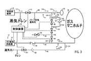
図2は、ガス燃料システムのガス燃料回路を空気でパージする第1の形態の運転における、タービンシステム12のための燃料管理システム10およびデュアルエアースチームパージシステム16(例えば、ガス燃料パージシステム)の一部分の一実施形態の概略図である。示されるように、蒸気供給部50(例えば、ボイラによって形成される)が蒸気供給ライン68を介して圧縮器34の圧縮器排出ポートのマニホルド66(例えば、デュアルエアースチームマニホルド(dual air and steam manifold))に連結される。蒸気供給ライン68は、蒸気供給ライン68に沿った圧縮器排出ポートのマニホルド66への流れを可能にしたりまたはその流れを制限したりするように構成されたバルブ70(例えば、蒸気シャットオフバルブ)を含む。 FIG. 2 illustrates a
パージシステム16は、バルブ70とマニホルド66との間で蒸気供給ライン68に連結されるライン72(例えば、パージ回路)を含む。ライン72は、平行なパージラインまたはパージ回路(すなわち、部分的に独立の回路)である空気パージ回路74と蒸気パージ回路76とに分割され、その後、回路74および76はガス燃料ライン40に連結されるかまたは繋げられる共通のラインまたはパージ回路78を形成する。特定の実施形態では、空気パージ回路74の直径は蒸気パージ回路76の直径より大きい。空気パージ回路74は、空気パージ回路74に沿った共通のパージ回路78への空気流れを可能にしたりまたはその流れを制限したりするように構成されたバルブ80(例えば、パージ空気バルブ)を含む。蒸気パージ回路76は、蒸気パージ回路76に沿った共通のパージ回路78への蒸気流れを制限するように構成されたオリフィス82(例えば、パージ蒸気オリフィス)を含む。特定の実施形態では、蒸気パージ回路は、蒸気パージ回路76に沿った共通のパージ回路78への蒸気流れを制限するためにオリフィス82の代わりに調整可能バルブを含んでもよい。共通のパージ回路78は、共通のパージ回路78に沿ったガス燃料ライン40への空気流れまたは蒸気流れを可能にしたりまたはその流れを制限したりするように構成された一対のバルブ84および86(例えば、ブロックバルブ)を含む。ライン88(例えば、抽気ライン)がバルブ84および86の間で共通のパージ回路78に連結される。このライン88は、可燃性流体のいかなる逆流もブリードオフするために通常は開いているバルブ90(例えば、抽気バルブ)を含む。同時に、バルブ84および86ならびに抽気バルブシステムは、ガス燃料によるガスタービンエンジン14の運転中に圧縮器排出ポートのマニホルド66への可燃性流体の起こり得る漏洩を低減するかまたは完全に排除するように構成される。 The
上で言及したように、共通のパージ回路78はガス燃料ライン40に連結される。燃料管理システム10が、ガス燃料ライン40を介してガスタービンエンジン14のガスマニホルド92にガス燃料36を供給する。ガス燃料ライン40は、ガスマニホルド92へのガス燃料36の流れを制御するように構成された1つまたは複数のバルブを含むことができる。パージ処理中、これらの1つまたは複数のバルブは閉じられる。ガス燃料ライン40および共通のパージ回路78の連結部の上流では、ガス燃料ライン40は、ガス燃料供給部36へのガス燃料36あるいは空気流れまたはガス流れの逆流を遮断するように構成されたバルブ94(例えば、チェックバルブ)を含む。 As mentioned above, the
パージシステム16はまた、ガスマニホルド92(例えば、ガス燃料ライン40の低い位置)と、共通のパージ回路78およびガス燃料ライン40の間の連結部との間で、ガス燃料ライン40に連結される排水ライン96を含む。排水ライン96はバルブ100(例えば、シャットオフバルブ)と直列になるようにオリフィス98を含む。バルブ100はオリフィス98の下流に配置される。排水ライン96は、蒸気によるパージ処理中に蒸気から形成されるすべての凝縮水を回収して排水するように構成される。さらに、蒸気はすべて排水ライン96を介して別の領域に通気されてもよい。 The
上で説明した制御装置18は、バルブ70、80、84、86、90、100に連結され、それらのバルブを開閉するように構成される。制御装置18は、バルブ70、80、84、86、90、100を開閉することにより、パージ制御論理56(例えば、非一時的な有形のコンピュータ可読媒体に記憶される命令)を介してパージシステム16を制御して、空気および蒸気によりガス燃料回路を順次パージすることを制御することができ、さらに、マニホルド66を介してガスタービンエンジン14に蒸気を供給することを制御することができる。さらに、制御装置18は、燃料移行制御論理54を介してガス燃料36から液体燃料38への移行またはその逆の移行を管理する。 The
上で言及したように、蒸気パラメータを蒸気注入許容閾値を満たす前に、パージシステム16(制御装置18を介する)は、液体燃料38でタービンシステム12を始動させて最初に空気でガス燃料回路をパージするように構成された(第1の形態の運転中)。矢印102で示されるように、圧縮器34の圧縮器排出ポートのマニホルド66から空気が抽出される。供給される空気の一部は、矢印104で示されるように、蒸気供給ライン68に沿って蒸気シャットオフバルブ70に向かうように流れる。第1の形態の運転中、蒸気シャットオフバルブ70は閉じられており、したがって、蒸気供給ライン68に沿ってバルブ70に向かって流れる空気は矢印106で示されるように排出され得る。バルブ70が閉じられている場合、蒸気供給部50によって供給される蒸気はすべて蒸気ドレンの方に進路を変更される。 As mentioned above, before the vapor parameters meet the vapor injection tolerance threshold, the purge system 16 (via the controller 18) starts the
空気の別の一部は、矢印108で示されるように、ライン72を通過して空気パージ回路74まで移動する。蒸気パージ回路76に沿うようにオリフィス82が配置されることから、空気は、蒸気回路76ではなく抵抗が最も少ない経路である空気パージ回路74を流れる。オリフィス82に跨る空気は、空気パージ回路74に沿った空気流れより圧力降下が大きくなる。このような設計により、パージシステム16が圧力降下を最小にすることが可能となり、また、空気パージ流れを維持することが可能となる。空気は開いているバルブ84および86を通って共通のパージ回路78に沿って継続して流れ、矢印110で示されるガス燃料ライン40への圧力降下は最小となる。空気でガス燃料36をパージする間、抽気バルブ90は閉じられている。したがって、液体燃料によるガスタービン14の運転中、空気は矢印112で示されるようにガス燃料ライン40に沿って流れてガス燃料システム(例えば、ガス燃料ライン40、燃料ノズル20、22、および、ガスマニホルド92)をパージする。空気でガス燃料回路をパージする間、起こり得るいかなる漏洩および圧力損失も防止するために排水バルブ100は閉じられている。空気の供給源(例えば、マニホルド66)とガス燃料ノズルシンクとの間の圧力差は小さい。パージシステム16の上記の構成は空気の継続的な流れを維持し、空気によるパージ処理中の圧力降下を最小にして圧力差の限界値に留める。 Another portion of the air travels through
蒸気注入許容閾値が満たされた後で、パージシステム16(制御装置18を介する)は図3に示される第2の形態の運転に移行し、ここでは、空気の代わりに蒸気でガス燃料システムのガス燃料回路をパージする。蒸気注入許容閾値は温度と圧力の関数である。温度に対する蒸気注入許容閾値は約250℃から425℃または315℃から375℃の範囲であってもよく、圧力は約3500kPaから5500kPaまたは4170kPaから4500kPaの範囲であってもよい。例えば、パージシステム16は、約315℃、320℃、325℃、330℃、335℃、340℃、345℃、350℃、355℃、360℃、365℃、370℃もしくは370℃以上の温度または任意の別の温度、および/あるいは、約4170kPa、4200kPa、4250kPa、4300kPa、4350kPa、4400kPa、4450kPaもしくは4500kPa以上の圧力または任意の別の圧力で、第2の形態の運転に移行してもよい。 After the vapor injection tolerance threshold has been met, the purge system 16 (via the controller 18) transitions to the second form of operation shown in FIG. 3, where steam instead of air is used for the gas fuel system. Purge the gas fuel circuit. The steam injection threshold is a function of temperature and pressure. The steam injection tolerance threshold for temperature may range from about 250 ° C. to 425 ° C. or 315 ° C. to 375 ° C., and the pressure may range from about 3500 kPa to 5500 kPa or 4170 kPa to 4500 kPa. For example, the
示されるように、蒸気は矢印122で示されるように蒸気供給部50(例えば、ボイラによって発生される)から流れ出て、矢印124で示されるように開いているバルブ70を通って蒸気供給ライン68に沿って流れる。蒸気の大部分(すなわち、第1の部分)(例えば、蒸気全体の約90パーセントを超える)は矢印126で示されるように圧縮器34の圧縮器排出ポートのマニホルド66に向かって流れる。一部の実施形態では、マニホルド66に向かって流れる蒸気の第1の部分は蒸気全体の約70パーセントから99パーセントの範囲であってもよい。マニホルド66内に流れる蒸気はタービンエンジン14のパワー出力を増大させる。マニホルド66に向かって流れる蒸気はマニホルド66から蒸気供給ライン68内へ流れることができるいかなる空気の圧力にも打ち勝つ。蒸気の少量部分(すなわち、第2の部分)(例えば、蒸気全体の約10パーセント未満)は矢印128で示されるようにライン72を通って流れ、矢印130、132に示されるように蒸気パージ回路76まで流れる。蒸気を介してガス回路内で継続的な流体流れを維持することにより、可燃性流体が再循環してガス燃料回路に戻る可能性が最小となる。一部の実施形態では、ライン72を通って蒸気パージ回路76まで流れる蒸気の第2の部分は蒸気全体の約1パーセントから30パーセントの範囲であってもよい。空気パージ回路74のパージ空気バルブ80は閉じられており、蒸気パージ回路76を通るように蒸気流れの進路を変更する。蒸気パージ回路76に沿って配置されるオリフィス82は、ガス燃料システムのガス燃料回路をパージするための蒸気流れの量を制限する。蒸気流れを制限することにより、オフィリス82は蒸気の大部分がマニホルド66に向かって確実に流れるようにする。 As shown, the steam flows out of the steam supply 50 (eg, generated by a boiler) as indicated by
空気パージ回路76に沿ってオフィリス82を横断する蒸気の一部は矢印134、136で示されるように共通のパージ回路に向かう。蒸気は開いているバルブ84、86を通って共通のパージ回路78に沿って継続して流れ、矢印138で示されるガス燃料ライン40への圧力降下が最小となる。蒸気でガス燃料36をパージする間、抽気バルブ90は閉じられている。したがって、液体燃料によるガスタービン14の運転中、蒸気は矢印140で示されるようにガス燃料ライン40に沿って流れてガス燃料システムのガス燃料回路(例えば、ガス燃料ライン40、燃料ノズル20および22、ならびに、ガスマニホルド92)をパージする。蒸気でガス燃料回路をパージする間、蒸気によりガスライン40内で形成されるすべての凝結水を回収して排水するために、排水バルブ100は開かれている。蒸気は矢印142、144で示されるように排水ライン96に沿って流れる。排水ライン96に沿って配置されるオリフィス98は、バルブ100および通気領域に向かって流れる蒸気を制限する。蒸気流れを制限することにより、オフィリス98は蒸気の大部分がガスマニホルド92に向かって確実に流れるようにする。図2および3の設計では、パージシステム16は、ガス燃料システムのガス燃料回路を空気および蒸気により二重パージすることを可能にし、同時に、多重燃料ガスタービンエンジン14のパワー出力を増大させるために蒸気を使用することを可能にする。さらに、パージシステム16は、概して、コーキング、ガス燃料ライン40および燃料ノズル20、22への燃焼生成物の逆流、ならびに、エンジンハードウェアの迅速な劣化を軽減するかまたは排除する。 A portion of the vapor that traverses the
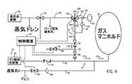
図4および5は、空気または蒸気のいずれかによりガス燃料ライン40をパージすることを可能にするように構成されたスリーウェイバルブ154を含むパージシステム16の一実施形態を示している。図4は、ガス燃料システムのガス燃料回路を空気によってパージする第1の形態の運転における、タービンシステム12のための燃料管理システム10およびデュアルエアースチームパージシステム16の一部分の一実施形態の概略図である。構造的に、燃料管理システム10、および、パージシステム16の大部分は、パージシステム16の一部分を除いて図2および3において上で説明された通りである。例えば、パージシステム16はスリーウェイバルブ154を含み、パージ空気バルブ80がない。さらに、空気パージ回路74および蒸気パージ回路76は異なる形で構成される。 4 and 5 illustrate one embodiment of a
パージシステム72は、蒸気供給ライン68に別個に連結される空気パージ回路74および蒸気パージ回路76を含む。スリーウェイバルブ154が蒸気供給ライン68に沿って空気パージ回路74とライン68との間の接続部のところに配置される。スリーウェイバルブ154は、蒸気供給ライン68に接合される第1のポート156と、圧縮器排出ポートのマニホルド66からのライン160(例えば、空気供給ライン)に接合される第2のポート158と、空気パージ回路74に接合される第3のポート162と含む。蒸気パージ回路76は、スリーウェイバルブ154と圧縮器34の圧縮器排出ポートのマニホルド66との間でライン160に連結される。空気パージ回路74および蒸気パージ回路76は平行なパージラインまたはパージ回路(すなわち、部分的に独立の回路)を形成し、これは、ガス燃料ライン40に連結されるかまたは繋げられる共通のラインまたはパージ回路78に収束する。特定の実施形態では、空気パージ回路74の直径は蒸気パージ回路76の直径より大きくてもよい。蒸気パージ回路76は、蒸気パージ回路76に沿った共通のパージ回路78までの蒸気流れを制限するように構成されたオフィリス82(例えば、パージ蒸気オフィリス)を含む。特定の実施形態では、蒸気パージ回路は、蒸気パージ回路76に沿った共通のパージ回路78への蒸気流れを制限するためにオフィリス82の代わりに調整可能バルブを含んでもよい。共通のパージ回路78は上で説明した通りである。 The
上で説明した制御装置18は、バルブ70、154(ポート156、158、162)、84、86、90、100に連結され、それらのバルブを開閉するように構成される。制御装置18は、バルブ70、154(ポート156、158、162)、84、86、90、100を開閉することにより、パージ制御論理56(例えば、非一時的な有形のコンピュータ可読媒体に記憶される命令)を介してパージシステム16を制御して、空気および蒸気を用いるガス燃料回路を順次パージすることを制御することができ、さらに、マニホルド66を介してガスタービンエンジン14に蒸気を供給することを制御することができる。さらに、制御装置18は、燃料移行制御論理54を介してガス燃料36から液体燃料38への移行またはその逆の移行を管理する。 The
上で言及したように、蒸気注入許容閾値を満たす前に、パージシステム16(制御装置18を介する)は、第1の形態の運転において、液体燃料38でタービンシステム12を始動させて最初に空気でガス燃料回路をパージするように構成される。バルブ70が閉じられている場合、蒸気供給部50からの提供される蒸気はすべて蒸気ドレンの方に進路を変更される。矢印164で示されるように、圧縮器34の圧縮器排出ポートのマニホルド66から空気が抽出される。供給された空気は、矢印164で示されるように、空気供給ライン160に沿ってスリーウェイバルブ154に向かって流れる。第1の形態の運転中、スリーウェイバルブ154の第1のポート156は閉じられており、第2のポート158および第3のポート162は開けられている。空気は矢印166で示されるようにポート158、162を通って空気パージ回路74内まで移動する。蒸気パージ回路76に沿ってオリフィス82が配置されることから、空気は、蒸気パージ回路76ではなく抵抗が最も少ない経路である空気パージ回路74に沿って流れる。オリフィス82に跨る空気は、空気パージ回路74に沿った空気流れより圧力降下が大きくなる。このような設計により、パージシステム16が圧力降下を最小にすることが可能となり、また、空気パージ流れを維持することが可能となる。空気は開いているバルブ84および86を通って共通のパージ回路78に沿って継続して流れ、矢印168、170で示されるガス燃料ライン40への圧力降下は最小となる。空気でガス燃料回路をパージする間、抽気バルブ90は閉じられている。したがって、液体燃料によるガスタービン14の運転中、空気は矢印172、174で示されるようにガス燃料ライン40に沿って流れてガス燃料システムのガス燃料回路(例えば、ガス燃料ライン40、燃料ノズル20および22、ならびに、ガスマニホルド66)をパージする。空気でガス燃料36をパージする間、起こり得るいかなる漏洩および圧力損失も軽減または排除するために排水バルブ100は閉じられている。空気の供給源(例えば、マニホルド66)とガス燃料ノズルシンクとの間の圧力差は小さい。パージシステム16の上記の構成は空気の継続的な流れを維持し、空気によるパージ処理中の圧力降下を最小にして圧力差の限界値未満に留める。 As noted above, prior to meeting the vapor injection tolerance threshold, the purge system 16 (via controller 18) is the first to operate the
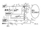
蒸気注入許容閾値が満たされた後で、パージシステム16(制御装置18を介する)は図5に示される第2の形態の運転に移行し、ここでは、空気の代わりに蒸気でガス燃料システムからのガス燃料36をパージする。蒸気注入許容閾値は温度と圧力の関数である。温度に対する蒸気注入許容閾値は約250℃から425℃または315℃から375℃の範囲であってもよく、圧力は約3500kPaから5500kPaまたは4170kPaから4500kPaの範囲であってもよい。例えば、パージシステム16は、約315℃、320℃、325℃、330℃、335℃、340℃、345℃、350℃、355℃、360℃、365℃、370℃もしくは370℃以上の温度または任意の別の温度、および/あるいは、約4170kPa、4200kPa、4250kPa、4300kPa、4350kPa、4400kPa、4450kPaもしくは4500kPa以上の圧力または任意の別の圧力で、第2の形態の運転に移行してもよい。 After the vapor injection tolerance threshold is met, the purge system 16 (via the controller 18) transitions to the second form of operation shown in FIG. 5, where the vapor is replaced by gas instead of air from the gas fuel system. The
図5に示される第2の形態の運転中、スリーウェイバルブ154の第1のポート156および第2のポート158は閉じられており、第3のポート162は閉じられている。示されるように、蒸気供給部50(例えば、ボイラによって発生される)から流れ出て、矢印184で示されるように開いているバルブ70を通って蒸気供給ライン68に沿って流れ、さらに、矢印186で示されるように開いているポート156、158を通ってライン160内まで流れる。蒸気の大部分(すなわち、第1の部分)(例えば、蒸気全体の約90パーセントを超える)は矢印186で示されるように圧縮器34の圧縮器排出ポートのマニホルド66に向かって流れる。一部の実施形態では、マニホルド66に向かって流れる蒸気の第1の部分は蒸気全体の約70パーセントから99パーセントの範囲であってもよい。マニホルド66に向かって流れる蒸気はマニホルド66からライン160内へ流れることができるいかなる空気の圧力にも打ち勝つ。マニホルド66内に流れる蒸気はタービンエンジン14のパワー出力を増大させる。蒸気の少量部分(すなわち、第2の部分)(例えば、蒸気全体の約10パーセント未満)は矢印188で示されるように蒸気パージ回路76内まで流れる。蒸気を介してガス回路内で継続的な流体流れを維持することにより、可燃性流体が再循環してガス燃料回路に戻る可能性が最小となる。一部の実施形態では、蒸気パージ回路76内まで流れる蒸気の第2の部分は蒸気全体の約1パーセントから30パーセントの範囲であってもよい。スリーウェイバルブ162の第3のポート162は閉じられており、蒸気パージ回路76を通るように蒸気流れの進路を変更する。蒸気パージ回路76に沿って配置されるオリフィス82は、ガス燃料システムのガス燃料回路をパージするための蒸気流れの量を制限する。蒸気流れを制限することにより、オフィリス82は蒸気の大部分がマニホルド66に向かって確実に流れるようにする。 During operation of the second configuration shown in FIG. 5, the
空気パージ回路76に沿ってオフィリス82を横断する蒸気の一部は矢印188、190で示されるように共通のパージ回路78に向かう。蒸気は開いているバルブ84、86を通って共通のパージ回路78に沿って継続して流れ、矢印192、194で示されるガス燃料ライン40への圧力降下が最小となる。蒸気でガス燃料回路をパージする間、抽気バルブ90は閉じられている。したがって、液体燃料によるガスタービン14の運転中、蒸気は矢印196、198で示されるようにガス燃料ライン40に沿って流れてガス燃料システムのガス燃料回路(例えば、ガス燃料ライン40、燃料ノズル20および22、ならびに、ガスマニホルド92)をパージする。蒸気でガス燃料回路をパージする間、蒸気によりガスライン40内で形成されるすべての凝結水を回収して排水するために、排水バルブ100は開かれている。蒸気は矢印200、202で示されるように排水ライン96に沿って流れる。排水ライン96に沿って配置されるオリフィス98は、バルブ100および通気領域に向かって流れる蒸気を制限する。蒸気流れを制限することにより、オフィリス98は蒸気の大部分がガスマニホルド92に向かって確実に流れるようにする。図4および5の設計では、パージシステム16は、ガス燃料システムのガス燃料回路を空気および蒸気により二重パージすることを可能にし、同時に、多重燃料ガスタービンエンジン14のパワー出力を増大させるために蒸気を使用することを可能にする。さらに、パージシステム16は、概して、コーキング、ガス燃料ライン40および燃料ノズル20、22への燃焼生成物の逆流、ならびに、エンジンハードウェアの迅速な劣化を軽減するかまたは排除する。 A portion of the vapor that traverses the
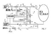
共通のパージ回路78に収束する平行な空気パージ回路74および蒸気パージ回路76に加えて、パージシステム16は図6および7に示される完全に独立の空気パージ回路74および蒸気パージ回路76を含むことができる。図6は、ガス燃料システムのガス燃料回路を空気によってパージする第1の形態の運転における、タービンシステム12のための燃料管理システム10およびデュアルエアースチームパージシステム16の一部分の一実施形態の概略図である。構造的に、蒸気供給ライン68、ガス燃料ライン40および排水ライン96に沿う構成要素は、パージシステム16が共通のパージ回路78に収束しない完全に独立の空気パージ回路74および蒸気パージ回路76を含むことを除いて、図2および3において上で説明された通りである。 In addition to the parallel
パージシステム16は、バルブ70とマニホルド60との間で蒸気供給ライン68に独立して連結されかつガス供給ライン40まで延在する空気パージ回路74および蒸気パージ回路76を含む。空気パージ回路74および蒸気パージ回路76は圧縮器排出ポートのマニホルド66および蒸気供給部50の近くで蒸気供給ライン68にそれぞれ連結される。空気パージ回路74は、ガス燃料ライン40への空気流れを可能にしたりまたはその流れを制限したりするように構成された一対のバルブ212および214(例えば、ブロックバルブ)を含む。ライン216(例えば、抽気ライン)がバルブ212および214の間で空気パージ回路74に連結される。このライン216は、蒸気によるパージ処理中にいかなる空気もブリードオフすることを可能にするバルブ218(例えば、パージ空気抽気バルブ)を含む。バルブ218は空気によるパージ処理中は閉じられ、蒸気によるパージ処理中は開いている。同時に、バルブ212および214ならびに抽気バルブシステムは、ガス燃料によるガスタービンエンジン14の運転中に圧縮器排出ポートのマニホルド66への可燃性流体の起こり得る漏洩を完全に防止するように構成される。 The
蒸気パージ回路76は、蒸気パージライン76に沿った蒸気流れを制限するように構成されたオフィリス82(例えば、パージ蒸気オフィリス)を含む。特定の実施形態では、蒸気パージ回路76は、オリフィス82の代わりに調整可能バルブを含む。オリフィス82の下流には、蒸気パージ回路76は、ガス燃料ライン40への蒸気流れを可能にしたりまたはその流れを制限したりするように構成された一対のバルブ220および222(例えば、ブロックバルブ)を含む。ライン224(例えば、抽気ライン)がバルブ220および222の間で蒸気パージ回路76に連結される。このライン224は、空気によるパージ処理中にいかなる蒸気もブリードオフすることを可能にするバルブ226(例えば、パージ蒸気抽気バルブ)を含む。バルブ226は蒸気によるパージ処理中は閉じられ、空気によるパージ処理中は開いている。同時に、バルブ220および222ならびに抽気バルブシステムは、ガス燃料によるガスタービンエンジン14の運転中に圧縮器排出ポートのマニホルド66への可燃性流体の起こり得る漏洩を完全に防止するように構成される。 The
上で説明した制御装置18は、バルブ70、212、214、218、220、222、226、100に連結され、それらのバルブを開閉するように構成される。制御装置18は、バルブ70、212、214、218、220、222、226、100を開閉することにより、パージ制御論理56(非一時的な有形のコンピュータ可読媒体に記憶される命令)を介してパージシステム16を制御して、空気および蒸気によりガス燃料36を順次パージすることを制御することができ、さらに、マニホルド66を介してガスタービンエンジン14に蒸気を供給することを制御することができる。さらに、制御装置18は、燃料移行制御論理54を介してガス燃料36から液体燃料38への移行またはその逆の移行を管理する。 The
上で言及したように、蒸気注入許容閾値を満たす前に、パージシステム16(制御装置18を介する)は、液体燃料38でタービンシステム12を始動させて最初に空気でガス燃料回路をパージするように構成された(第1の形態の運転中)。矢印228で示されるように、圧縮器34の圧縮器排出ポートのマニホルド66から空気が抽出される。供給される空気の一部は、矢印230で示されるように、蒸気供給ライン68に沿って蒸気シャットオフバルブ70に向かうように流れる。第1の形態の運転中、蒸気シャットオフバルブ70は閉じられており、したがって、蒸気供給ライン68に沿ってバルブ70に向かって流れる空気は矢印231で示されるように排出され得る。バルブ70が閉じられている場合、蒸気供給部50によって供給される蒸気はすべて蒸気ドレンの方に進路を変更される。 As mentioned above, before meeting the vapor injection tolerance threshold, the purge system 16 (via controller 18) starts the
空気の別の一部は、矢印232で示されるように、ライン68を通過して空気パージ回路74まで移動する。蒸気パージ回路76に沿ってオリフィス82が配置されることから、空気は、蒸気パージ回路76ではなく抵抗が最も少ない経路である空気パージ回路74を流れる。オリフィス82に跨る空気は、空気パージ回路74に沿った空気流れより圧力降下が大きくなる。このような設計により、パージシステム16が圧力降下を最小にすることが可能となり、また、空気パージ流れを維持することが可能となる。空気は開いているバルブ212、214を通って空気パージ回路74に沿って継続して流れ、矢印232、234で示されるガス燃料ライン40への圧力降下は最小となる。上で言及したように、空気によりガス燃料36をパージする間、抽気バルブ218は閉じられている。また、空気によりガス燃料回路をパージする間、抽気バルブ226は開けられている。したがって、液体燃料によるガスタービン14の運転中、空気は矢印236で示されるようにガス燃料ライン40に沿って流れてガス燃料システム(例えば、ガス燃料ライン40、燃料ノズル20、22、および、ガスマニホルド92)をパージする。空気でガス燃料回路をパージする間、起こり得るいかなる漏洩および圧力損失も防止するために排水バルブ100は閉じられている。空気の供給源(例えば、マニホルド66)とガス燃料ノズルシンクとの間の圧力差は小さい。パージシステム16の上記の構成は空気の継続的な流れを維持し、空気によるパージ処理中の圧力降下を最小にして圧力差の限界値未満に留める。 Another portion of the air travels through
蒸気注入許容閾値が満たされた後で、パージシステム16(制御装置18を介する)は図7に示される第2の形態の運転に移行し、ここでは、空気の代わりに蒸気でガス燃料システムのガス燃料回路をパージする。蒸気注入許容閾値は温度と圧力の関数である。温度に対する蒸気注入許容閾値は約250℃から425℃または315℃から375℃の範囲であってもよく、圧力は約3500kPaから5500kPaまたは4170kPaから4500kPaの範囲であってもよい。例えば、パージシステム16は、約315℃、320℃、325℃、330℃、335℃、340℃、345℃、350℃、355℃、360℃、365℃、370℃もしくは370℃以上の温度または任意の別の温度、および/あるいは、約4170kPa、4200kPa、4250kPa、4300kPa、4350kPa、4400kPa、4450kPaもしくは4500kPa以上の圧力または任意の別の圧力で、第2の形態の運転に移行してもよい。 After the vapor injection tolerance threshold is met, the purge system 16 (via the controller 18) transitions to the second form of operation shown in FIG. 7, where steam instead of air is used for the gas fuel system. Purge the gas fuel circuit. The steam injection threshold is a function of temperature and pressure. The steam injection tolerance threshold for temperature may range from about 250 ° C. to 425 ° C. or 315 ° C. to 375 ° C., and the pressure may range from about 3500 kPa to 5500 kPa or 4170 kPa to 4500 kPa. For example, the
示されるように、蒸気は矢印246で示されるように蒸気供給部50(例えば、ボイラによって発生される)から流れ出て、矢印248で示されるように開いているバルブ70を通って蒸気供給ライン68に沿って流れる。蒸気の大部分(すなわち、第1の部分)(例えば、蒸気全体の約90パーセントを超える)は矢印250で示されるように圧縮器34の圧縮器排出ポートのマニホルド66に向かって流れる。一部の実施形態では、マニホルド66に向かって流れる蒸気の第1の部分は蒸気全体の約70パーセントから99パーセントの範囲であってもよい。マニホルド66内に流れる蒸気はタービンエンジン14のパワー出力を増大させる。蒸気の少量部分(すなわち、第2の部分)(例えば、蒸気全体の約10パーセント未満)は矢印252で示されるように蒸気パージ回路76内へと流れる。蒸気を介してガス回路内で継続的な流体流れを維持することにより、可燃性流体が再循環してガス燃料回路に戻ることが防止される。一部の実施形態では、蒸気パージ回路76内へと流れる蒸気の第2の部分は蒸気全体の約1パーセントから30パーセントの範囲であってもよい。蒸気パージ回路76に沿って配置されるオリフィス82は、ガス燃料システムのガス燃料回路をパージするための蒸気流れの量を制限する。蒸気流れを制限することにより、オフィリス82は蒸気の大部分がマニホルド66に向かって確実に流れるようにする。 As shown, the steam flows out of the steam supply 50 (eg, generated by a boiler) as indicated by
蒸気の一部は矢印252で示されるように蒸気パージ回路76に沿ってオフィリス82を横断する。蒸気は開いているバルブ220、222を通って蒸気パージ回路76に沿って継続して流れ、矢印254、256で示されるガス燃料ライン40への圧力降下が最小となる。上で言及したように、空気でガス燃料回路をパージする間、抽気バルブ218は開けられている。また、空気でガス燃料回路をパージする間、抽気バルブ226は閉じられている。したがって、液体燃料によるガスタービン14の運転中、蒸気は矢印258で示されるようにガス燃料ライン40に沿って流れてガス燃料システムのガス燃料回路(例えば、ガス燃料ライン40、燃料ノズル20、22、および、ガスマニホルド92)をパージする。蒸気でガス燃料回路をパージする間、蒸気によりガスライン40内で形成されるすべての凝結水を回収して排水するために、排水バルブ100は開かれている。蒸気は矢印260、262で示されるように排水ライン96に沿って流れる。排水ライン96に沿って配置されるオリフィス98は、バルブ100および通気領域に向かって流れる蒸気を制限する。蒸気流れを制限することにより、オフィリス98は蒸気の大部分がガスマニホルド92に向かって確実に流れるようにする。図6および7の設計では、パージシステム16は、ガス燃料システムのガス燃料回路を空気および蒸気により二重パージすることを可能にし、同時に、多重燃料ガスタービンエンジン14のパワー出力を増大させるために蒸気を使用することを可能にする。さらに、パージシステム16は、コーキング、ガス燃料ライン40および燃料ノズル20、22への燃焼生成物の逆流、ならびに、エンジンハードウェアの迅速な劣化を軽減するかまたは排除する。 A portion of the steam traverses the
図1〜7を参照するパージシステム16の上述の実施形態の使用を以下のプロセスで説明する。図8は、液体燃料によるガスタービンエンジン14の運転中にガス燃料システムのガス燃料回路をパージするためのプロセス272の一実施形態のフローチャートである。具体的には、プロセス272は、ガス燃料システムのガス燃料回路を空気および蒸気により二重パージすることを可能にしさらに同時に多重燃料ガスタービンエンジン14のパワー出力を増大させるために蒸気を使用することを可能にするための上で説明したパージシーケンスを採用する。さらに、このパージシーケンスは、コーキング、ガス燃料ライン40および燃料ノズルへの燃焼生成物の逆流、ならびに、エンジンハードウェアの迅速な劣化を軽減するかまたは排除する。上で説明した燃料制御装置18がプロセス272を実施する。 The use of the above-described embodiment of the
プロセス272は、液体燃料38により多重燃料ガスタービンエンジン14の運転を開始することを含む(ブロック274)。液体燃料によるガスタービンエンジンの運転が開始される間(ブロック274)、第1の形態で動作するパージシステム16(制御装置18を介する)が、上述したように、最初に、ガス燃料システムのガス燃料回路(例えば、ガス燃料ライン40、燃料ノズル20、22、および、ガスマニホルド)を空気によりパージする(ブロック276)。空気によるパージ処理の第1の形態は、蒸気供給部50からの蒸気のパラメータ(例えば、温度および圧力)を蒸気注入許容閾値を満たす前に行われる。蒸気注入許容閾値は温度と圧力の関数である。温度に対する蒸気注入許容閾値は約250℃から425℃または315℃から375℃の範囲であってもよく、圧力は約3500kPaから5500kPaまたは4170kPaから4500kPaの範囲であってもよい。空気によるパージシステム16のパージ処理では、制御装置18が蒸気のパラメータ(例えば、温度および圧力)を監視する(ブロック278)。制御装置18は、蒸気パラメータが蒸気注入許容閾値を満たすか否かを判定する(ブロック280)。蒸気パラメータが蒸気注入許容閾値を満たさない場合、制御装置18は蒸気パラメータの監視を継続する(ブロック278)。しかし、蒸気パラメータが蒸気注入許容閾値を満たす場合、パージシステム16(制御装置18を介する)が第2の形態での運転に移行し、空気の代わりに蒸気でガス燃料システムのガス燃料回路をパージする(ブロック282)。さらに、第2の形態では、エンジン14のパワー出力を増大させるためにマニホルド66を介してガスタービンエンジン14に蒸気が供給される。
開示される実施形態の技術的効果には、液体燃料によるガスタービンエンジン14の運転中にガス燃料システムのガス燃料回路を空気および蒸気により二重パージするためのシステムおよび方法を提供することが含まれる。具体的には、開示される実施形態には、制御装置18を介して(例えば、パージ制御論理56を使用する)空気および蒸気によりガス燃料回路を順次パージするように構成されたデュアルエアースチームパージシステム16(例えば、ガス燃料パージシステム)が含まれる。蒸気注入許容閾値を満たす前に、パージシステム16は最初に空気でガス燃料システムのガス燃料回路をパージする。蒸気注入許容閾値が満たされた後で、パージシステム16は、次いで、蒸気でガス燃料システムのガス燃料回路をパージし、同時に、エンジン14のパワー出力を増大させるためにマニホルド66を介してガスタービンエンジン14に蒸気が供給される。パージシステム16は、共通のパージ回路78に収束する部分的に独立の空気パージ回路74および蒸気パージ回路76、または、完全に独立の空気パージ回路74および蒸気パージ回路76を含むことができる。パージシステム16のこの構成は、ガス燃料システムのガス回路内で流体(例えば、空気または蒸気)の継続的な流れを維持する。さらに、パージシステム16は、ガス燃料システムのガス燃料回路を空気および蒸気により二重パージすることを可能にし、同時に、多重燃料ガスタービンエンジン14のパワー出力を増大させるために蒸気を使用することを可能にする。さらに、パージシステム16は、コーキング、ガス燃料ライン40および燃料ノズル20、22への燃焼生成物の逆流、ならびに、エンジンハードウェアの迅速な劣化を軽減または排除する。 Technical effects of the disclosed embodiments include providing a system and method for dual purging gas fuel circuits of a gas fuel system with air and steam during operation of a
ここに記載される説明は、最良の形態を含めた本発明を開示するために、さらには、任意のデバイスまたはシステムを製造および使用することならびに採用される任意の方法を実施することを含めて、当業者が本発明を実施することを可能にするために、複数の例を使用する。特許を受けることができる本発明の範囲は、特許請求の範囲によって定義され、当業者には思い付く別の例を含むことができる。このような別の例は、特許請求の範囲の文字通りの意味と違わない構造的要素を有する場合には、または、特許請求の範囲の文字通りの意味とほぼ違わない等価の構造的要素を含む場合には、特許請求の範囲内にあることが意図される。 The description set forth herein includes the manufacture and use of any device or system and the implementation of any method employed to disclose the invention, including the best mode. Several examples are used to enable one of ordinary skill in the art to practice the invention. The patentable scope of the invention is defined by the claims, and may include other examples that occur to those skilled in the art. Such other examples have structural elements that do not differ from the literal meaning of the claims, or include equivalent structural elements that do not substantially differ from the literal meaning of the claims. Is intended to be within the scope of the claims.
10 燃料管理システム
12 タービンシステム
14 ガスタービンエンジン
16 デュアルエアースチームパージシステム
18 燃料制御装置
20 燃料ノズル
22 燃料ノズル
24 燃焼器
26 燃料燃焼器
28 燃料燃焼器
30 タービン
32 シャフト
34 圧縮器
35 発電機
36 ガス燃料
38 液体燃料
40 主燃料ライン
42 主燃料ライン
44 バルブ
46 バルブ
48 パージ回路
50 蒸気供給部
52 空気供給部
54 燃料移行制御論理
56 パージ制御論理
66 マニホルド
68 蒸気供給ライン
70 バルブ
72 ライン
74 空気パージ回路
76 蒸気パージ回路
78 共通のパージ回路
80 バルブ
82 オリフィス
84 バルブ
86 バルブ
88 ライン
90 バルブ
92 ガスマニホルド
94 バルブ
96 排水ライン
98 オリフィス
100 バルブ
154 スリーウェイバルブ
156 第1のポート
158 第2のポート
160 ライン
162 第3のポート
212 バルブ
214 バルブ
216 ライン
218 バルブ
220 バルブ
222 バルブ
224 ライン
226 バルブDESCRIPTION OF
Claims (20)
Translated fromJapanese液体燃料による前記ガスタービンの運転中に前記ガス燃料システムのガス燃料回路をパージするように構成されたガス燃料パージシステムであって、空気および蒸気で順次前記ガス燃料回路をパージするように構成されたガス燃料パージシステムと
を含むシステム。A multi-fuel gas turbine configured to operate with both a liquid fuel system and a gas fuel system and comprising a compressor, a combustor and a turbine;
A gas fuel purge system configured to purge a gas fuel circuit of the gas fuel system during operation of the gas turbine with liquid fuel, wherein the gas fuel circuit is configured to sequentially purge the gas fuel circuit with air and steam. Gas fuel purge system.
を備えるシステム。A dual air steam purge system configured to purge a gas fuel circuit coupled to a multi-fuel gas turbine during operation of the gas turbine with liquid fuel so as to purge the gas fuel circuit with air A dual air steam purge system comprising an air purge circuit configured and a steam purge circuit configured to purge the gas fuel circuit with steam.
A system comprising:
液体燃料での前記多重燃料ガスタービンの運転を開始するステップと、
最初に空気で前記ガス燃料回路をパージするステップと、
蒸気供給部の蒸気パラメータが蒸気注入許容閾値を満たすか否かを判定するために前記蒸気パラメータを監視するステップと、
次いで、前記蒸気パラメータが前記蒸気注入許容閾値を満たしたとき蒸気で前記ガス燃料回路をパージするステップと
を含む方法。A method for purging a gas fuel circuit of a multiple fuel gas turbine comprising:
Initiating operation of the multi-fuel gas turbine with liquid fuel;
First purging the gas fuel circuit with air;
Monitoring the steam parameter to determine whether the steam parameter of the steam supply satisfies a steam injection tolerance threshold; and
And then purging the gas fuel circuit with steam when the steam parameters meet the steam injection tolerance threshold.
Applications Claiming Priority (2)
| Application Number | Priority Date | Filing Date | Title |
|---|---|---|---|
| US13/294,088 | 2011-11-10 | ||
| US13/294,088US9650955B2 (en) | 2011-11-10 | 2011-11-10 | System for purging gas fuel circuit for a gas turbine engine |
Publications (2)
| Publication Number | Publication Date |
|---|---|
| JP2013104427A JP2013104427A (en) | 2013-05-30 |
| JP5993282B2true JP5993282B2 (en) | 2016-09-14 |
Family
ID=47143744
Family Applications (1)
| Application Number | Title | Priority Date | Filing Date |
|---|---|---|---|
| JP2012244035AActiveJP5993282B2 (en) | 2011-11-10 | 2012-11-06 | System for purging a gas fuel circuit for a gas turbine engine |
Country Status (4)
| Country | Link |
|---|---|
| US (1) | US9650955B2 (en) |
| EP (1) | EP2592250B1 (en) |
| JP (1) | JP5993282B2 (en) |
| CN (1) | CN103104345B (en) |
Families Citing this family (25)
| Publication number | Priority date | Publication date | Assignee | Title |
|---|---|---|---|---|
| FR2989736B1 (en)* | 2012-04-18 | 2014-05-16 | Ge Energy Products France Snc | METHOD FOR PURGING A GAS TURBINE |
| US9909499B2 (en) | 2014-04-04 | 2018-03-06 | General Electric Company | Fuel drainage and purge system and method |
| US10215060B2 (en)* | 2014-11-06 | 2019-02-26 | Powerphase Llc | Gas turbine efficiency and power augmentation improvements utilizing heated compressed air |
| FR3030629B1 (en)* | 2014-12-23 | 2017-02-03 | Ge Energy Products France Snc | INSTALLATION AND METHOD FOR SUPPLYING A COMBUSTION CHAMBER HAVING A VENTILATED CAVITY BY HOT AIR FROM PURGE |
| US10247110B2 (en)* | 2015-09-23 | 2019-04-02 | General Electric Company | Method and system for reliable gas to liquid transfer |
| US10378447B2 (en) | 2016-09-30 | 2019-08-13 | General Electric Company | System and method for purging fuel or coolant from turbomachine |
| WO2018216331A1 (en)* | 2017-05-26 | 2018-11-29 | 三浦工業株式会社 | Hydrogen combustion boiler |
| US11156163B2 (en) | 2019-10-04 | 2021-10-26 | Hamilton Sundstrand Corporation | Fluid injection systems having fluid line purging |
| US11572840B2 (en)* | 2019-12-03 | 2023-02-07 | General Electric Company | Multi-mode combustion control for a rotating detonation combustion system |
| EP3832091B1 (en)* | 2019-12-04 | 2023-06-14 | Ansaldo Energia Switzerland AG | Gas turbine assembly for power plant application fed by at least two different fuels (fuel-gas or fuel-oil) and a method for operating this assembly when switching fuels or when operating this assembly with fuel-oil |
| CN113982758B (en)* | 2021-11-09 | 2023-04-07 | 烟台杰瑞石油装备技术有限公司 | Gas supply system, gas supply method, and equipment equipped with turbine engine |
| US11359554B2 (en) | 2020-03-05 | 2022-06-14 | General Electric Company | System and method for fuel nozzle cleaning during engine operation |
| US11261803B2 (en) | 2020-03-05 | 2022-03-01 | General Electric Company | Method and system for fuel nozzle cleaning during engine operation |
| FR3110197B1 (en)* | 2020-05-14 | 2022-12-23 | Ge Energy Products France Snc | REACTIVE GAS FUEL PURGE SYSTEM |
| US11639687B2 (en)* | 2020-10-22 | 2023-05-02 | Pratt & Whitney Canada Corp. | Fuel injectors and method of purging fuel injectors |
| CN112460637A (en)* | 2020-10-27 | 2021-03-09 | 中国船舶重工集团公司第七0三研究所 | Dual-fuel gas turbine bleed purging system |
| US11306661B1 (en)* | 2020-12-04 | 2022-04-19 | General Electric Company | Methods and apparatus to operate a gas turbine engine with hydrogen gas |
| CN112879160A (en)* | 2021-03-23 | 2021-06-01 | 烟台杰瑞石油装备技术有限公司 | Purging system and purging method for turbine fracturing truck group and turbine fracturing truck group |
| US11808219B2 (en)* | 2021-04-12 | 2023-11-07 | Pratt & Whitney Canada Corp. | Fuel systems and methods for purging |
| US12044178B2 (en) | 2022-01-06 | 2024-07-23 | Ge Infrastructure Technology Llc | System and method for air cooling fuel purge flow |
| US11946378B2 (en) | 2022-04-13 | 2024-04-02 | General Electric Company | Transient control of a thermal transport bus |
| CN114810358B (en)* | 2022-04-25 | 2024-02-20 | 中国船舶重工集团公司第七0三研究所 | Low-emission dual-fuel system of gas turbine and control method thereof |
| US20230366353A1 (en)* | 2022-05-13 | 2023-11-16 | General Electric Company | Purge system for a hydrogen fuel system |
| US11927142B2 (en) | 2022-07-25 | 2024-03-12 | General Electric Company | Systems and methods for controlling fuel coke formation |
| GB2628838A (en)* | 2023-04-06 | 2024-10-09 | Siemens Energy Global Gmbh & Co Kg | Gas turbine supply system |
Family Cites Families (26)
| Publication number | Priority date | Publication date | Assignee | Title |
|---|---|---|---|---|
| JPS6048618B2 (en)* | 1978-11-22 | 1985-10-28 | 株式会社日立製作所 | Gaseous fuel system purge system |
| JPS6017626A (en)* | 1983-07-08 | 1985-01-29 | Hitachi Ltd | Fuel purge method |
| US4893467A (en)* | 1988-07-13 | 1990-01-16 | Gas Research Institute | Control system for use with steam injected gas turbine |
| US4969324A (en)* | 1988-07-13 | 1990-11-13 | Gas Research Institute | Control method for use with steam injected gas turbine |
| JP2856860B2 (en)* | 1990-07-31 | 1999-02-10 | 株式会社東芝 | Gas turbine equipment |
| GB9025778D0 (en)* | 1990-11-27 | 1991-01-09 | Rolls Royce Plc | Improvements in or relating to gas generators |
| JPH11210494A (en) | 1998-01-26 | 1999-08-03 | Toshiba Corp | Purge device for gas turbine fuel supply device and method of operating purge device |
| US6145294A (en) | 1998-04-09 | 2000-11-14 | General Electric Co. | Liquid fuel and water injection purge system for a gas turbine |
| EP0952317A3 (en) | 1998-04-21 | 2002-04-17 | Mitsubishi Heavy Industries, Ltd. | Purging system for a gas turbine fuel supply |
| JPH11324720A (en)* | 1998-05-08 | 1999-11-26 | Mitsubishi Heavy Ind Ltd | Gas turbine fuel oil purge system |
| EP0955457A3 (en) | 1998-05-08 | 2002-07-17 | Mitsubishi Heavy Industries, Ltd. | Gas turbine fuel system |
| US6367239B1 (en)* | 1998-12-09 | 2002-04-09 | General Electric Company | Fuel delivery systems and method |
| JP2001153364A (en)* | 1999-11-25 | 2001-06-08 | Hitachi Ltd | Gas turbine combustor |
| US6438963B1 (en) | 2000-08-31 | 2002-08-27 | General Electric Company | Liquid fuel and water injection purge systems and method for a gas turbine having a three-way purge valve |
| JP4115659B2 (en)* | 2000-10-30 | 2008-07-09 | 株式会社東芝 | Gas turbine fuel supply system |
| JP3807272B2 (en)* | 2001-09-18 | 2006-08-09 | 株式会社日立製作所 | Reformed fuel-fired gas turbine and its fuel system purge method |
| JP4130909B2 (en)* | 2003-09-26 | 2008-08-13 | 株式会社日立製作所 | Double fuel-fired gas turbine fuel supply system |
| US7950238B2 (en)* | 2006-10-26 | 2011-05-31 | General Electric Company | Method for detecting onset of uncontrolled fuel in a gas turbine combustor |
| US7770400B2 (en) | 2006-12-26 | 2010-08-10 | General Electric Company | Non-linear fuel transfers for gas turbines |
| US20090025396A1 (en)* | 2007-07-24 | 2009-01-29 | General Electric Company | Parallel turbine fuel control valves |
| US20110036092A1 (en)* | 2009-08-12 | 2011-02-17 | General Electric Company | Methods and Systems for Dry Low NOx Combustion Systems |
| US20110265488A1 (en)* | 2010-04-29 | 2011-11-03 | General Electric Company | ALTERNATE METHOD FOR DILUENT INJECTION FOR GAS TURBINE NOx EMISSIONS CONTROL |
| US9239013B2 (en)* | 2011-01-03 | 2016-01-19 | General Electric Company | Combustion turbine purge system and method of assembling same |
| US8340886B2 (en)* | 2011-03-07 | 2012-12-25 | General Electric Company | System and method for transitioning between fuel supplies for a combustion system |
| RU2013143396A (en)* | 2011-03-31 | 2015-05-10 | Дженерал Электрик Компани | POWER FORCING DEVICE WITH DYNAMIC DYNAMIC PROCESSES |
| US9267433B2 (en)* | 2011-10-24 | 2016-02-23 | General Electric Company | System and method for turbine combustor fuel assembly |
- 2011
- 2011-11-10USUS13/294,088patent/US9650955B2/enactiveActive
- 2012
- 2012-11-06JPJP2012244035Apatent/JP5993282B2/enactiveActive
- 2012-11-08EPEP12191894.0Apatent/EP2592250B1/enactiveActive
- 2012-11-09CNCN201210445683.2Apatent/CN103104345B/enactiveActive
Also Published As
| Publication number | Publication date |
|---|---|
| CN103104345A (en) | 2013-05-15 |
| EP2592250A3 (en) | 2017-05-10 |
| EP2592250B1 (en) | 2020-02-26 |
| US9650955B2 (en) | 2017-05-16 |
| CN103104345B (en) | 2017-03-01 |
| US20130118178A1 (en) | 2013-05-16 |
| JP2013104427A (en) | 2013-05-30 |
| EP2592250A2 (en) | 2013-05-15 |
Similar Documents
| Publication | Publication Date | Title |
|---|---|---|
| JP5993282B2 (en) | System for purging a gas fuel circuit for a gas turbine engine | |
| CN101526217B (en) | Fuel supply method for gas turbine and combustor | |
| JP6266292B2 (en) | System and method for heating fuel in a combined cycle gas turbine | |
| CN102678337A (en) | System and method for transitioning between fuel supplies for a combustion system | |
| US9759130B2 (en) | Gas turbine engine with cooling system | |
| JP2015518540A (en) | System and method for stoichiometric EGR gas turbine system | |
| US9188061B2 (en) | System for turbine combustor fuel assembly | |
| US9435258B2 (en) | System and method for heating combustor fuel | |
| CN106461216A (en) | Systems and methods of controlling a gas turbine engine | |
| US9303562B2 (en) | Methods and systems for operating gas turbine engines | |
| JP2015045331A (en) | System and method for controlling fuel distributions in combustor in gas turbine engine | |
| JP6253066B2 (en) | Method of partial load CO reduction operation and gas turbine for a two-stage combustion gas turbine | |
| JP2012041882A (en) | System for supplying fuel of gas turbine combustor and method for supplying fuel of gas turbine combustor | |
| JP6779974B2 (en) | Systems and methods for supplying highly reactive fuels to combustors | |
| JP6247503B2 (en) | Exhaust gas recirculation combustion control method for equipment equipped with a combustion device | |
| RU2610371C2 (en) | System and method of fuel purge (versions) | |
| JP2013185585A (en) | Method of operating combustor from liquid fuel operation to gas fuel operation | |
| CN118922620A (en) | Ignition device and ignition method for highly reactive fuel gas |
Legal Events
| Date | Code | Title | Description |
|---|---|---|---|
| A621 | Written request for application examination | Free format text:JAPANESE INTERMEDIATE CODE: A621 Effective date:20151029 | |
| TRDD | Decision of grant or rejection written | ||
| A977 | Report on retrieval | Free format text:JAPANESE INTERMEDIATE CODE: A971007 Effective date:20160720 | |
| A01 | Written decision to grant a patent or to grant a registration (utility model) | Free format text:JAPANESE INTERMEDIATE CODE: A01 Effective date:20160726 | |
| A61 | First payment of annual fees (during grant procedure) | Free format text:JAPANESE INTERMEDIATE CODE: A61 Effective date:20160819 | |
| R150 | Certificate of patent or registration of utility model | Ref document number:5993282 Country of ref document:JP Free format text:JAPANESE INTERMEDIATE CODE: R150 | |
| R250 | Receipt of annual fees | Free format text:JAPANESE INTERMEDIATE CODE: R250 | |
| R250 | Receipt of annual fees | Free format text:JAPANESE INTERMEDIATE CODE: R250 | |
| R250 | Receipt of annual fees | Free format text:JAPANESE INTERMEDIATE CODE: R250 | |
| R250 | Receipt of annual fees | Free format text:JAPANESE INTERMEDIATE CODE: R250 | |
| R250 | Receipt of annual fees | Free format text:JAPANESE INTERMEDIATE CODE: R250 | |
| S111 | Request for change of ownership or part of ownership | Free format text:JAPANESE INTERMEDIATE CODE: R313113 | |
| R350 | Written notification of registration of transfer | Free format text:JAPANESE INTERMEDIATE CODE: R350 | |
| R250 | Receipt of annual fees | Free format text:JAPANESE INTERMEDIATE CODE: R250 | |
| R250 | Receipt of annual fees | Free format text:JAPANESE INTERMEDIATE CODE: R250 |