JP5993145B2 - Actuator - Google Patents
ActuatorDownload PDFInfo
- Publication number
- JP5993145B2 JP5993145B2JP2011282222AJP2011282222AJP5993145B2JP 5993145 B2JP5993145 B2JP 5993145B2JP 2011282222 AJP2011282222 AJP 2011282222AJP 2011282222 AJP2011282222 AJP 2011282222AJP 5993145 B2JP5993145 B2JP 5993145B2
- Authority
- JP
- Japan
- Prior art keywords
- unit
- power
- authentication
- supplied
- operating
- Prior art date
- Legal status (The legal status is an assumption and is not a legal conclusion. Google has not performed a legal analysis and makes no representation as to the accuracy of the status listed.)
- Expired - Fee Related
Links
- 238000010248power generationMethods0.000claimsdescription32
- 230000001105regulatory effectEffects0.000claimsdescription30
- 238000000926separation methodMethods0.000description18
- 238000002955isolationMethods0.000description4
- 230000005389magnetismEffects0.000description2
- RYGMFSIKBFXOCR-UHFFFAOYSA-NCopperChemical compound[Cu]RYGMFSIKBFXOCR-UHFFFAOYSA-N0.000description1
- XEEYBQQBJWHFJM-UHFFFAOYSA-NIronChemical group[Fe]XEEYBQQBJWHFJM-UHFFFAOYSA-N0.000description1
- 238000007792additionMethods0.000description1
- 238000010586diagramMethods0.000description1
- 230000005611electricityEffects0.000description1
- 230000007613environmental effectEffects0.000description1
- 230000007774longtermEffects0.000description1
- 230000004048modificationEffects0.000description1
- 238000012986modificationMethods0.000description1
Images


Landscapes
- Lock And Its Accessories (AREA)
Description
Translated fromJapanese本発明は、認証手段と物理的な動作を行う動作手段とを備える作動装置に関する。 The present invention relates to an operating device including an authentication unit and an operation unit that performs a physical operation.
従来、外部からの電源供給を受けることなく、認証動作及び解錠動作が行われ、電源用の外部配線を無くすことができる認証装置を備えるキャビネットがあり、このようなキャビネット(什器)では、引手部に加えられる開放操作を受けて発電を行い、これによる電力供給を受けて認証装置(認証手段)が起動して認証動作が行われるとともに、錠装置(動作手段)を駆動して扉を開放可能な状態にしている(例えば、特許文献1参照)。 2. Description of the Related Art Conventionally, there is a cabinet having an authentication device that can perform an authentication operation and an unlocking operation without receiving external power supply, and can eliminate external wiring for power supply. In response to the opening operation applied to the unit, the power generation is performed. Upon receiving the power supply, the authentication device (authentication means) is activated to perform the authentication operation, and the lock device (operation means) is driven to open the door. It is in a possible state (see, for example, Patent Document 1).
しかしながら、特許文献1に記載のキャビネット(什器)にあっては、錠装置(動作手段)は、物理的な解錠動作を行うために大きな電力を必要としているが、この解錠動作の前に、認証装置(認証手段)の認証動作により電力が消費されてしまい、錠装置を作動させるための充分な電力が確保できなくなる問題があり、特に、引手部に加えられる開放操作による手動発電により電力を確保しているため、充分な電力量を確保できなくなる場合があり、上記問題が頻繁に生じてしまうようになっている。 However, in the cabinet described in Patent Document 1, the lock device (operation means) requires a large amount of electric power to perform a physical unlocking operation, but before this unlocking operation, However, there is a problem that power is consumed by the authentication operation of the authentication device (authentication means), and sufficient power for operating the lock device cannot be secured. In particular, power is generated by manual power generation by an opening operation applied to the handle part. Therefore, there is a case where a sufficient amount of electric power cannot be secured, and the above-mentioned problem occurs frequently.
本発明は、このような問題点に着目してなされたもので、省電力化を図ることができ、かつ動作手段に供給される充分な電力量を確保できる作動装置を提供することを目的とする。 The present invention has been made paying attention to such problems, and aims to provide an operating device that can save power and can secure a sufficient amount of power supplied to operating means. To do.
前記課題を解決するために、本発明の作動装置は、
第1電力供給部から第1被供給部に電力が供給されることで認証動作を行う認証手段と、第2電力供給部から第2被供給部に電力が供給されることで物理的な動作を行う動作手段と、を備え、
前記動作手段には、手動等の操作がなされる操作部の操作に応じて動作を行う動作部材が設けられるとともに、前記第2電力供給部から前記第2被供給部に電力を供給されることで前記動作部材の動作の規制または非規制を選択的に行う規制部材が設けられ、
前記第2電力供給部から前記第2被供給部に供給される電力は、前記操作部の操作に応じて正方向または逆方向に流れる構成となっており、
前記認証手段により認証が許可されたときに、スイッチ部のON/OFF状態の切り換えにより、前記正方向または逆方向のいずれか一方の前記電力の流れが許容され、該電力の流れる方向に応じて、前記規制部材による前記動作部材の動作の規制または非規制の選択が行われることを特徴としている。
この特徴によれば、認証手段は、認証動作とスイッチ部に供給される電力のON/OFF状態の切り換えのみを行うため、認証手段が省電力で動作できるようになり、かつ物理的な動作を行う動作手段に供給される電力は、認証手段に供給される電力と別電源とすることができ、動作手段に供給される充分な電力量を確保できるようになる。In order to solve the above-mentioned problem, the actuating device of the present invention comprises:
Authentication means for performing an authentication operation by supplying power from the first power supply unit to the first supplied unit, and physical operation by supplying power from the second power supply unit to the second supplied unit Operating means for performing
The operating means is provided with an operating member that performs an operation in response to an operation of an operating unit that is operated manually or the like, and power is supplied from the second power supply unit to the second supplied unit. A regulating member for selectively regulating or non-regulating the operation of the operating member is provided,
The power supplied from the second power supply unit to the second supplied unit is configured to flow in the forward direction or the reverse direction according to the operation of the operation unit,
When authentication is permitted by the authentication means, switching of the ON / OFF state of the switch unit allows the power flow in either the forward direction or the reverse direction, depending on the direction in which the power flows. The operation member is controlled to be restricted or non-regulated by the restricting member.
According to this feature, since the authentication means only performs the authentication operation and the switching of the ON / OFF state of the power supplied to the switch unit, the authentication means can operate with power saving and perform physical operation. The power supplied to the operating means to be performed can be a separate power source from the power supplied to the authentication means, and a sufficient amount of power supplied to the operating means can be secured.
本発明の作動装置は、
前記第2電力供給部は、手動等の操作がなされる操作部の操作に応じて発電を行う手動発電部となっていることを特徴としている。
この特徴によれば、手動発電により動作手段の動作に必要な電力量を確保して作動装置の省電力化を図ることができる。The actuating device of the present invention comprises:
The second power supply unit is a manual power generation unit that generates power in response to an operation of an operation unit that is operated manually or the like.
According to this feature, it is possible to secure the amount of power necessary for the operation of the operating means by manual power generation and to save power in the operating device.
本発明の作動装置は、
前記第2電力供給部及び前記第2被供給部は、整流器により正方向または逆方向に電流を流す少なくとも2系統の電力線により互いに接続されており、前記スイッチ部が少なくとも1系統の電力線に設けられることを特徴としている。
この特徴によれば、少なくとも2系統の電力線と整流器という簡素な構成で、動作部材の規制または非規制を行う動作手段を構成でき、認証手段は、少なくとも1系統の電力線のスイッチ部を制御するだけで済み、認証手段は、第2電力供給部から第2被供給部に供給される電力の流れの方向を把握する必要がなく、作動装置の省電力化を図ることができる。The actuating device of the present invention comprises:
The second power supply unit and the second supplied unit are connected to each other by at least two power lines that allow current to flow in the forward or reverse direction by a rectifier, and the switch unit is provided on at least one power line. It is characterized by that.
According to this feature, it is possible to configure an operation means for regulating or non-regulating the operation member with a simple configuration of at least two systems of power lines and rectifiers, and the authentication section only controls the switch unit of at least one system of power lines. Thus, the authentication unit does not need to know the direction of the flow of power supplied from the second power supply unit to the second supplied unit, and can save power in the operating device.
本発明の作動装置は、
第1電力供給部から第1被供給部に電力が供給されることで認証動作を行う認証手段と、第2電力供給部から第2被供給部に電力が供給されることで物理的な動作を行う動作手段と、を備え、
前記動作手段には、手動等の操作がなされる操作部の操作に応じて動作を行う動作部材が設けられるとともに、前記第2電力供給部から前記第2被供給部に電力を供給されることで前記動作部材の動作の規制または非規制を選択的に行う規制部材が設けられ、
前記規制部材は、磁極を有するとともに、前記第2被供給部は、前記規制部材の近傍に配置された電磁石となっており、
前記認証手段により認証が許可されたときに、スイッチ部がON状態に切り換わることで前記電磁石が通電し、該電磁石により前記規制部材の向きが切り換わり、前記規制部材により前記動作部材の動作の規制または非規制の少なくとも一方が許容されることを特徴としている。
この特徴によれば、電磁石によって小さな磁力を与えることにより、規制部材の向きを容易に切り換えることができ、磁性を有する規制部材と電磁石という簡素な構成で、動作部材の規制または非規制を行うことができ、作動装置の省電力化を図ることができる。The actuating device of the present invention comprises:
Authentication means for performing an authentication operation by supplying power from the first power supply unit to the first supplied unit, and physical operation by supplying power from the second power supply unit to the second supplied unit Operating means for performing
The operating means is provided with an operating member that performs an operation in response to an operation of an operating unit that is operated manually or the like, and power is supplied from the second power supply unit to the second supplied unit. A regulating member for selectively regulating or non-regulating the operation of the operating member is provided,
The regulating member has a magnetic pole, and the second supplied portion is an electromagnet arranged in the vicinity of the regulating member,
When authentication is permitted by the authentication unit, the electromagnet is energized by switching the switch unit to the ON state, the direction of the regulating member is switched by the electromagnet, and the operation of the operation member is performed by the regulating member. It is characterized in that at least one of regulation or non-regulation is allowed.
According to this feature, the direction of the regulating member can be easily switched by applying a small magnetic force by the electromagnet, and the operation member is regulated or unregulated with a simple configuration of a magnetic regulating member and an electromagnet. Thus, power saving of the operating device can be achieved.
本発明に係る作動装置を実施するための形態を実施例に基づいて以下に説明する。 EMBODIMENT OF THE INVENTION The form for implementing the actuator concerning this invention is demonstrated below based on an Example.
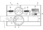
実施例に係る作動装置につき、図1から図10を参照して説明する。図1の符号1は、オフィス等に設置される什器1である。この什器1は、上下3段の引出し2(収納部)が設けられている。そして、これらの引出し2には、引出し2を開放するための取手部3が設けられており、最上段の引出し2には、引出し2の施解錠を行うための摘み部4(操作部)と、施解錠の認証を行う認証装置5(認証手段)と、が設けられている。なお、取手部3は、ラッチ機構(図示略)と連係されており、ラッチ機構により引出し2が不用意に開放されないようにするとともに、取手部3を把持することでラッチ機構が解除されて引出し2が開放可能となる。 The actuator according to the embodiment will be described with reference to FIGS. Reference numeral 1 in FIG. 1 is a fixture 1 installed in an office or the like. The fixture 1 is provided with three drawers 2 (storage units) in the upper and lower stages. These
図2に示すように、引出し2の内部には、施解錠装置6(動作手段)が設けられている。この施解錠装置6は、前述した摘み部4を有しており、後述するように、この施解錠装置6が認証装置5とも連動されており、認証装置5により認証が許可された操作者が施解錠を行うことができる。なお、認証装置5と施解錠装置6とにより本実施例における作動装置を構成している。 As shown in FIG. 2, a lock / unlock device 6 (operation means) is provided inside the
さらに、施解錠装置6は、引出し2を開放不能にするための矩形状の棒状部材をとなっている動作部材7を有しており、この動作部材7が係合方向(左方向)に移動されることで、その先端部が什器1の側板34に形成された受け座8(被係合部)に挿入されて係合し、引出し2が開放不能になる。 Furthermore, the locking /
また、動作部材7が解除方向(右方向)に移動されることで、その先端部が什器1の側板34の受け座8から脱し、引出し2が開放可能になる。そして、図10に示すように、認証装置5は、操作者が暗証番号を入力するためのテンキー9と、認証が許可されたか否かを表示するインジケータ10と、パネル状をなす太陽電池パネル11(第1電力供給部)と、これらが接続された制御部35(第1被供給部)と、を備えている。なお、テンキー9とインジケータ10と太陽電池パネル11とは、引出し2の前面板12の前面に設けられている(図1及び図2参照)。 Further, when the
また、認証装置5は、太陽電池パネル11から供給される電力により稼働されるようになっている。さらに、認証装置5の制御部35には、太陽電池パネル11にて発電された電力を蓄えるバッテリ(図示略)が設けられている。なお、認証装置5は、電気回路の作動を行うのみで、物理的な機械の動作を行わないようになっているため、室内灯などの微弱な光を用いて太陽電池パネル11により発電される微量な電力であっても、認証装置5が充分に作動されるようになっている。 The
次に、施解錠装置6について詳述する。図3及び図4に示すように、施解錠装置6は、引出し2の前面側を閉塞する前面板12に内蔵されており、この施解錠装置6は、前面板12内に固定的に配置された取付金具13をベースとしている。この取付金具13には、動作部材7を直線状に案内するために、上下2条の凸条で形成される案内部14(経路)が設けられている。この案内部14に沿って動作部材7が左右方向に移動可能となっている。 Next, the locking / unlocking
前述した摘み部4は、正面視で略円形状をなし、前面板12の前面に設けられた摘み配置部材15内に配置されている。そして、この摘み部4の後面側には、摘み部4の回転と同時に回転される操作ギア16が設けられている。この操作ギア16の歯部17は、円形状をなす操作ギア16の円周上の一部に形成されている。なお、摘み部4と操作ギア16とは、連動軸18により相対的に固定されている(図3参照)。また、操作ギア16の後面側には、操作ギア16の円周近傍に設けられた操作ピン19が設けられている。 The
図4に示すように、動作部材7には、操作ピン19が係合するための上下に延びる長孔20が形成されている。操作者が摘み部4を回転操作させることで操作ギア16が周方向に回転するようになり、それに伴って操作ピン19の位置が操作ギア16の回転に伴って移動され、操作者の手動操作力が操作ピン19を介して長孔20から動作部材7に伝達される。本実施例では、操作者が摘み部4を反時計回りに回転させることで、動作部材7が係合方向(左方向)に移動するとともに、操作者が摘み部4を時計回りに回転させることで、動作部材7が脱離方向(右方向)に移動するようになっている。 As shown in FIG. 4, the operating
また、施解錠装置6の取付金具13の後部には、発電機21(第2電力供給部,手動発電部)が取り付けられている(図3参照)。この発電機21は直流電流を発電するようになっている。そして、操作ギア16の上方位置には、発電機21を駆動する発電ギア22が設けられている。なお、この発電ギア22は、発電機21の駆動軸24に対して相対的に固定されており、発電ギア22は、駆動軸24を中心として回転されるようになっている。この発電ギア22には、その全周に歯部23が形成されており、操作ギア16の歯部17が係合されるようになっている。 A generator 21 (second power supply unit, manual power generation unit) is attached to the rear portion of the mounting
さらに、発電ギア22は、その左右端部に弾性を有する弾性部材として構成される左右一対のコイルバネ25が取り付けられている。なお、コイルバネ25の一端は、発電ギア22に取り付けられるとともに、コイルバネ25の他端は、取付金具13に取り付けられている。また、この発電ギア22は、その周方向に回転自在になっているが、左右両コイルバネ25の付勢力によって、発電ギア22は、その周方向の定位置に安定的に保持されるようになっている。 Furthermore, the
さらに、案内部14の右端側近傍には、回転軸26により回転自在となっている略円形状をなす回転体27(規制部材)が設けられている。この回転体27は、その一部が直線状に切り欠かれて切欠部28が形成されている。図4に示すように、回転体27が回転され、その切欠部28が下方位置にあるときには、動作部材7が最右方側の脱離位置まで移動できる。図9に示すように、回転体27が回転され、その切欠部28が上方位置にあるときには、回転体27の一部が案内部14の内部に配置されるようになり、動作部材7が回転体27に接触してその移動動作が規制(ロック)されるようになっている。 Further, in the vicinity of the right end side of the
図4に示すように、回転体27の内部には、磁性を有する永久磁石29(磁性部材)が設けられている。この永久磁石29に外部から磁力が加わることで、回転体27が回転されるようになっている。なお、回転体27の切欠部28が下方位置にあるときに、永久磁石29の磁極の向きは、左方側がN極で右方側がS極となっている。そして、回転体27の上方位置には、回転体27に磁力を加える電磁石30(第2被供給部)が配置されている。この電磁石30は、鉄心の周りに銅線により形成されたコイルを配置したものとなっている。 As shown in FIG. 4, a permanent magnet 29 (magnetic member) having magnetism is provided inside the rotating
図10に示すように、発電機21の2つの電極31から2本の電線32が延びており、この2本の電線32を介して発電機21が電磁石30のコイルに接続されている。なお、この2本の電線32のうち、一方の電線32は、その途中で分岐され、かつ分岐後に再び合流されるように分離された分離部32a,32bを有している。この2つの分離部32a,32bには、それぞれの分離部32a,32bを流れる電流の方向を一方向にする整流器36a,36bが設けられている。そして、各分離部32a,32bを流れる電流は、正方向または逆方向の異なる方向に流れるようになっている。なお、この分離部32a,32bにより、正方向または逆方向に電流を流す少なくとも2系統の電力線32が構成される。 As shown in FIG. 10, two
なお、一方の分離部32bには、認証装置5によって制御されるON/OFFスイッチ部33が設けられている。操作者が暗証番号をテンキー9に暗証番号を入力して認証が許可された場合には、分離部32bのスイッチ部33がON状態(通電可能状態)となる。また、操作者が暗証番号をテンキー9に暗証番号を入力して認証が不可だった場合には、分離部32bのスイッチ部33がOFF状態(通電不能状態)となる。 One
また、後述するように、操作者が施錠操作を行う際に、電線32を介して発電機21から電磁石30に電流が流れるようになっている。この施錠操作を行う際に電線32を流れる電流を正方向とすると、この正方向の電流の流れは、分離部32aを介して通電可能状態となっている。 As will be described later, when the operator performs the locking operation, a current flows from the
そのため、操作者が施錠操作を行う際には、特に認証装置5にて認証を行う必要はない。操作者が施錠操作を行う際には、先ず操作者は摘み部4を反時計回りに回転させる。そして、摘み部4の回転に伴い操作ギア16が回転されることで、動作部材7が係合方向(左方向)に移動される。 Therefore, when the operator performs the locking operation, it is not necessary to perform authentication in the
図5に示すように、動作部材7が所定量移動されたとき、即ち操作ギア16が所定量回転されたときに、操作ギア16の歯部17が発電ギア22の歯部23と係合し、互いにギア16,22が連係されるようになっている。そして、操作ギア16の反時計回りの回転とともに、発電ギア22が時計回りに回転される。この発電ギア22の回転とともに、発電ギア22の左右のコイルバネ25が延び始める。 As shown in FIG. 5, when the
そして、操作者の手動操作により摘み部4を回転させて操作ギア16が回転され続けることで、摘み部4に加わる手動操作によるエネルギーがコイルバネ25を延ばすようになる。このコイルバネ25には、動作部材7の移動に伴うストローク、即ち摘み部4の回転に伴うストロークの一部の動作が、コイルバネ25の延長という機械的エネルギーとして蓄えられる。 Then, by manually rotating the
図6に示すように、さらに操作ギア16が所定量回転されると、操作ギア16の歯部17が発電ギア22の歯部23から外れ、互いにギア16,22の連係状態が断たれる。そして、コイルバネ25が有する復元力により一気にコイルバネ25が短縮し、コイルバネ25に蓄えられた機械的エネルギーが瞬時に放出されて発電ギア22を反時計回りに回転させる。 As shown in FIG. 6, when the
この発電ギア22の回転によって発電機21にて発電が行われる。なお、このとき、発電機21が発電した電力は、直流電流となっている。さらに、コイルバネ25に蓄えられた機械的エネルギーが瞬時に放出されるため、高い電圧を発生させることができる。 The
また、発電機21が発電した電力は、回転体27の上方位置に配置された電磁石30に供給される。そして、通電された電磁石30は一時的に磁化されて、電磁石30の左端部がN極、右端部がS極となる磁場が発生する。このとき、電磁石30が発生せる磁力により、回転体27の内部の永久磁石29が磁力の影響を受けて、回転体27が回転軸26と中心として回転され、その向きが切り換わるようになっている。なお、回転体27は180°回転されることで、その向きが切り換わる。なお、動作部材7は、回転体27の向きに係らず最左方側の係合位置まで移動できる。 Further, the electric power generated by the
図5及び図6に示すように、回転体27の向きが切り換わる前は、回転体27の切欠部28が下方位置に配置されている。電磁石30が通電されることで、回転体27の向きが切り換わった後は、回転体27の一部が案内部14内に配置されるようになる。なお、この案内部14内に配置された回転体27の一部が、後述するように動作部材7の移動を規制(ロック)する規制部材となる。 As shown in FIGS. 5 and 6, the
また、操作者が解錠操作を行う際に、電線32を介して発電機21から電磁石30に電流が流れるようになっている。この解錠操作を行う際に電線32を流れる電流を逆方向とすると、この逆方向の電流の流れは、分離部32bのスイッチ部33がOFF状態とされることで通電不能状態となっている。 Further, when the operator performs an unlocking operation, a current flows from the
そのため、操作者が解錠を行う際には、先ず認証装置5にて認証を行う。操作者が暗証番号をテンキー9に暗証番号を入力して認証が許可された場合には、分離部32bのスイッチ部33がON状態(通電可能状態)となる。その後、操作者は摘み部4を時計回りに回転させる。そして、摘み部4の回転に伴い操作ギア16が回転されることで、動作部材7が脱離方向(右方向)に移動される。 Therefore, when the operator unlocks, the
図7に示すように、動作部材7が所定量移動されたとき、即ち操作ギア16が所定量回転されたときに、操作ギア16の歯部17が発電ギア22の歯部23と係合し、互いにギア16,22が連係されるようになっている。そして、操作ギア16の時計回り回転とともに、発電ギア22が反時計回りに回転される。この発電ギア22の回転とともに、発電ギア22の左右のコイルバネ25が延び始める。 As shown in FIG. 7, when the
そして、操作者の手動操作により摘み部4を回転させて操作ギア16が回転され続けることで、摘み部4に加わる手動操作によるエネルギーがコイルバネ25を延ばすようになる。このコイルバネ25には、動作部材7の移動に伴うストローク、即ち摘み部4の回転に伴うストロークの一部の動作が、コイルバネ25の延長という機械的エネルギーとして蓄えられる。 Then, by manually rotating the
図8に示すように、さらに操作ギア16が所定量回転されると、操作ギア16の歯部17が発電ギア22の歯部23から外れ、互いにギア16,22の連係状態が断たれる。そして、コイルバネ25が有する復元力により一気にコイルバネ25が短縮し、コイルバネ25に蓄えられた機械的エネルギーが瞬時に放出されて発電ギア22を時計回りに回転させる。この発電ギア22の回転によって発電機21にて発電が行われる。なお、このとき、発電機21が発電した電力は、前述の施錠操作時に発電した電力と同様に直流電流となっているが、その電極の極性は、逆になっている。 As shown in FIG. 8, when the
即ち、発電機21が発電した電力は、回転体27の上方位置に配置された電磁石30に供給されるが、電磁石30では、電磁石30の左端部がS極、右端部がN極となる磁場が発生する。このように、摘み部4が係合方向に操作されたときの発電機21の電極の極性と、摘み部4が脱離方向に操作されたときの発電機21の電極の極性と、が互いに反転するようになっている。 That is, the electric power generated by the
そして、電磁石30が発生せる磁力により、回転体27の内部の永久磁石29が磁力の影響を受け、回転体27が回転軸26と中心として回転され、その向きが切り換わるようになっている。このように、電磁石30で動作する回転体27を電磁石30の磁極により制御できるようになり、操作者が摘み部4を手動操作することにより回転体27を制御することができる。 The
また、回転体27の向きが切り換わった後は、回転体27の切欠部28が下方位置に配置され、動作部材7が脱離位置まで移動可能となる。操作者は、摘み部4を時計回りに回転させて動作部材7を脱離位置まで移動させることで、什器1と引出し2が開放可能となる。 In addition, after the direction of the
なお、操作者が解錠操作を行う際には、先ず認証装置5にて認証を行うようになっているが、認証装置5において、操作者が暗証番号をテンキー9に暗証番号を入力して認証が不可だった場合には、発電機21と電磁石30との間の電線32の分離部32bのスイッチ部33がOFF状態(通電不能状態)となる(図10参照)。この状態で操作者が摘み部4を回転させると、操作ギア16及び発電ギア22は回転されるようになっているが、分離部32bのスイッチ部33がOFF状態(通電不能状態)であるため、電磁石30が通電されることはなく、回転体27が回転されないようになっている。 When the operator performs the unlocking operation, authentication is first performed by the
例えば、図9に示すように、認証装置5において認証が不可だった場合には、操作者が解錠を行う際に摘み部4を操作しても、動作部材7の端部が回転体27に接触してその移動が規制されるようになっている。この状態では、動作部材7の先端部は、什器1の側板34の受け座8(被係合部)に挿入されて係合された状態となっており、引出し2を開放することができない。 For example, as shown in FIG. 9, when authentication is not possible in the
以上、本実施例における什器1では、認証装置5は、認証動作とスイッチ部33に供給される電力のON/OFF状態の切り換えのみを行うため、認証装置5が省電力で動作できるようになり、かつ物理的な動作を行う施解錠装置6に供給される電力は、認証装置5に供給される電力と別電源とすることができ、施解錠装置6に供給される充分な電力量を確保できるようになる。 As described above, in the fixture 1 according to the present embodiment, the
また、施解錠装置6(ロック装置)の電磁石30は、手動操作によって発電を行う発電機21から電力の供給を受けることで、手動発電により施解錠装置6の動作に必要な電力量を確保して什器1の省電力化を図ることができる。かつ認証装置5のみが太陽電池パネル11などから電力の供給を受ければよくなり、環境保護に配慮した什器1とすることができる。 Moreover, the
また、認証装置5は、スイッチ部33のON/OFFの制御を行い、回転体27による動作部材7の動作の規制または非規制の少なくとも一方が許容されることで、動作部材7の動作の規制または非規制を選択的に行うことができるとともに、動作部材7が行う動作は、摘み部4の操作に応じて決定されるため、認証装置5若しくは別途の記憶装置により、動作部材7の動作態様を記憶しておく必要がなく、什器1の省電力化を図ることができる。 In addition, the
また、回転体27による動作部材7の動作の規制または非規制の選択は、摘み部4の操作に応じて決定され、認証装置5は、発電機21から電磁石30に供給される電力の流れのいずれか一方の流れの許容の制御を行い、該電力の他方の流れは常に許容されるようになっているため、認証装置5は、動作部材7の動作の規制または非規制のいずれか一方を制御するだけで済み、認証装置5若しくは別途の記憶装置により、回転体27の状態を記憶しておく必要がなく、什器1の省電力化を図ることができる。 Further, the selection of the restriction or non-regulation of the operation of the
また、2系統の電力線32(分離部32a,32b)と整流器36a,36bという簡素な構成で、動作部材7の規制または非規制を行う施解錠装置6を構成でき、認証装置5は、1系統の電力線32(分離部32b)のスイッチ部33を制御するだけで済み、認証装置5は、発電機21から電磁石30に供給される電力の流れの方向を把握する必要がなく、什器1の省電力化を図ることができる。 Further, the locking / unlocking
また、電磁石30によって小さな磁力を与えることにより、回転体27の向きを容易に切り換えることができ、磁性を有する回転体27と電磁石30という簡素な構成で、動作部材7の規制または非規制を行うことができ、什器1の省電力化を図ることができる。 Further, by applying a small magnetic force by the
以上、本発明の実施例を図面により説明してきたが、具体的な構成はこれら実施例に限られるものではなく、本発明の要旨を逸脱しない範囲における変更や追加があっても本発明に含まれる。 Although the embodiments of the present invention have been described with reference to the drawings, the specific configuration is not limited to these embodiments, and modifications and additions within the scope of the present invention are included in the present invention. It is.
例えば、前記実施例では、オフィス等に設置される什器1の引出し2に対して本発明が適用された施解錠装置6が設けられているが、施解錠装置6は、什器1の引出し2のみならず、観音扉式の開閉部を有する什器や蓋体により収納部を開閉する什器に本発明が適用された施解錠装置6を設けるようにしてもよい。さらに、什器1のみならず、家屋の玄関のドアや窓等を施錠する施解錠装置や機械器具などに広い分野に適用できることは明らかである。 For example, in the above-described embodiment, the locking / unlocking
また、前記実施例では、認証装置5の電源として太陽電池パネル11を用いているが、太陽電池パネル11に替えて小型乾電池等を用いた場合に、その寿命が延びるようになり、長期間電池交換しないで使用することができる。 Moreover, in the said Example, although the
また、前記実施例では、電線32の分離部32bにスイッチ部33が設けられ、操作者が解錠操作を行う際に、認証装置5にて認証を行う必要があるが、電線32の分離部32bにスイッチ部33が設けずに、電線32の分離部32aにスイッチ部33を設けるようにし、操作者が施錠操作を行う際に、認証装置5にて認証を行う必要があるように構成してもよい。 Moreover, in the said Example, although the
また、前記実施例では、電線32が分離部32a,32bにより2系統にされているが、認証装置5にて認証を行う必要がある操作態様に応じて、分離部を3つや4つやそれ以上設け、電線32を3系統や4系統やそれ以上設けるようにしてもよい。 Moreover, in the said Example, although the
1 什器
2 引出し(収納部)
4 摘み部(操作部)
5 認証装置(認証手段)
6 施解錠装置(動作手段)
7 動作部材
11 太陽電池パネル(第1電力供給部)
21 発電機(第2電力供給部,手動発電部)
27 回転体(規制部材)
30 電磁石(第2被供給部)
32 電線
32a,32b 分離部
33 スイッチ部
35 制御部(第1被供給部)
36a,36b 整流器1
4 Picking part (operation part)
5. Authentication device (authentication means)
6 Locking and unlocking device (operation means)
7 Operating
21 Generator (second power supply unit, manual power generation unit)
27 Rotating body (regulating member)
30 Electromagnet (second supply part)
32
36a, 36b Rectifier
Claims (4)
Translated fromJapanese前記動作手段には、手動等の操作がなされる操作部の操作に応じて動作を行う動作部材が設けられるとともに、前記第2電力供給部から前記第2被供給部に電力を供給されることで前記動作部材の動作の規制または非規制を選択的に行う規制部材が設けられ、
前記第2電力供給部から前記第2被供給部に供給される電力は、前記操作部の操作に応じて正方向または逆方向に流れる構成となっており、
前記認証手段により認証が許可されたときに、スイッチ部のON/OFF状態の切り換えにより、前記正方向または逆方向のいずれか一方の前記電力の流れが許容され、該電力の流れる方向に応じて、前記規制部材による前記動作部材の動作の規制または非規制の選択が行われることを特徴とする作動装置。Authentication means for performing an authentication operation by supplying power from the first power supply unit to the first supplied unit, and physical operation by supplying power from the second power supply unit to the second supplied unit Operating means for performing
The operating means is provided with an operating member that performs an operation in response to an operation of an operating unit that is operated manually or the like, and power is supplied from the second power supply unit to the second supplied unit. A regulating member for selectively regulating or non-regulating the operation of the operating member is provided,
The power supplied from the second power supply unit to the second supplied unit is configured to flow in the forward direction or the reverse direction according to the operation of the operation unit,
When authentication is permitted by the authentication means, switching of the ON / OFF state of the switch unit allows the power flow in either the forward direction or the reverse direction, depending on the direction in which the power flows. The actuating device is characterized in that selection of restriction or non-regulation of the operation of the operation member by the restriction member is performed.
前記動作手段には、手動等の操作がなされる操作部の操作に応じて動作を行う動作部材が設けられるとともに、前記第2電力供給部から前記第2被供給部に電力を供給されることで前記動作部材の動作の規制または非規制を選択的に行う規制部材が設けられ、
前記規制部材は、磁極を有するとともに、前記第2被供給部は、前記規制部材の近傍に配置された電磁石となっており、
前記認証手段により認証が許可されたときに、スイッチ部がON状態に切り換わることで前記電磁石が通電し、該電磁石により前記規制部材の向きが切り換わり、前記規制部材により前記動作部材の動作の規制または非規制の少なくとも一方が許容されることを特徴とする作動装置。Authentication means for performing an authentication operation by supplying power from the first power supply unit to the first supplied unit, and physical operation by supplying power from the second power supply unit to the second supplied unit Operating means for performing
The operating means is provided with an operating member that performs an operation in response to an operation of an operating unit that is operated manually or the like, and power is supplied from the second power supply unit to the second supplied unit. A regulating member for selectively regulating or non-regulating the operation of the operating member is provided,
The regulating member has a magnetic pole, and the second supplied portion is an electromagnet arranged in the vicinity of the regulating member,
When authentication is permitted by the authentication unit, the electromagnet is energized by switching the switch unit to the ON state, the direction of the regulating member is switched by the electromagnet, and the operation of the operation member is performed by the regulating member. An operating device characterized in that at least one of regulation or non-regulation is allowed.
Priority Applications (1)
| Application Number | Priority Date | Filing Date | Title |
|---|---|---|---|
| JP2011282222AJP5993145B2 (en) | 2011-12-22 | 2011-12-22 | Actuator |
Applications Claiming Priority (1)
| Application Number | Priority Date | Filing Date | Title |
|---|---|---|---|
| JP2011282222AJP5993145B2 (en) | 2011-12-22 | 2011-12-22 | Actuator |
Publications (2)
| Publication Number | Publication Date |
|---|---|
| JP2013130040A JP2013130040A (en) | 2013-07-04 |
| JP5993145B2true JP5993145B2 (en) | 2016-09-14 |
Family
ID=48907803
Family Applications (1)
| Application Number | Title | Priority Date | Filing Date |
|---|---|---|---|
| JP2011282222AExpired - Fee RelatedJP5993145B2 (en) | 2011-12-22 | 2011-12-22 | Actuator |
Country Status (1)
| Country | Link |
|---|---|
| JP (1) | JP5993145B2 (en) |
Families Citing this family (2)
| Publication number | Priority date | Publication date | Assignee | Title |
|---|---|---|---|---|
| MX2019014363A (en) | 2017-06-02 | 2020-07-27 | Lock Ii L L C | Device and methods for providing a lock for preventing unwanted access to a locked enclosure. |
| JP7089241B2 (en)* | 2018-05-09 | 2022-06-22 | ジョー・プリンス竹下株式会社 | Lock device for storage |
Family Cites Families (4)
| Publication number | Priority date | Publication date | Assignee | Title |
|---|---|---|---|---|
| JPH05311930A (en)* | 1992-05-11 | 1993-11-22 | Fujitsu Ltd | Access control device |
| JP2000204806A (en)* | 1999-01-13 | 2000-07-25 | Mitsubishi Electric Corp | Power generator for door |
| JP3930386B2 (en)* | 2002-06-21 | 2007-06-13 | 株式会社東海理化電機製作所 | Electronic key system |
| JP4461896B2 (en)* | 2004-04-28 | 2010-05-12 | トヨタ自動車株式会社 | In-vehicle device remote control device and portable device |
- 2011
- 2011-12-22JPJP2011282222Apatent/JP5993145B2/ennot_activeExpired - Fee Related
Also Published As
| Publication number | Publication date |
|---|---|
| JP2013130040A (en) | 2013-07-04 |
Similar Documents
| Publication | Publication Date | Title |
|---|---|---|
| WO2013085057A1 (en) | Power generator | |
| US8624447B2 (en) | Electrical energy-generating device and remote control equipped with such a device | |
| US10190336B2 (en) | Magnetically activated door-lock device | |
| ES2559240T3 (en) | Closing installation comprising a device for access control with an electromechanical converter | |
| JP5993145B2 (en) | Actuator | |
| US20110210564A1 (en) | Bi-stable actuator for electronic lock | |
| CN204238686U (en) | A kind of indoor cabinet door electromagnetic lock | |
| US8988843B2 (en) | Actuator module, system for locking-unlocking a door | |
| EP2400470B1 (en) | Arrangement for closing an opening for the output and/or input of notes of an automated teller machine | |
| JP6139101B2 (en) | Locking device | |
| CN207148495U (en) | A fully closed aperture electromagnetic aperture device | |
| US20190080831A1 (en) | Bistable electromechanical actuator | |
| JP6139053B2 (en) | Locking device | |
| WO2023141995A1 (en) | Dual power transfer switch | |
| WO2019137317A1 (en) | Electrically-controlled magnetic connecting device and electric vehicle battery-swapping apparatus | |
| KR20080002595U (en) | Door lock device | |
| JP2014091913A (en) | Store fixture with lock device | |
| KR100543957B1 (en) | Door lock | |
| CN206158391U (en) | Electric five prevent using padlock device | |
| CN114613619B (en) | Switch anti-miswiring protection device | |
| BR102013014538B1 (en) | DC ELECTRICAL MACHINE TYPE CROSS-INTERLOCKED SWITCH THAT HAS RING AND BRUSH FOR DRIVING AND AUXILIARY EXCITATION WINDING | |
| ES2909203T3 (en) | locking device | |
| JP2000265718A (en) | Lock device of door in furniture | |
| CN101538958A (en) | Mechanical and electronic compound lock | |
| CN103276985B (en) | A kind of link lever type electronic strongbox locking device |
Legal Events
| Date | Code | Title | Description |
|---|---|---|---|
| A621 | Written request for application examination | Free format text:JAPANESE INTERMEDIATE CODE: A621 Effective date:20141111 | |
| RD04 | Notification of resignation of power of attorney | Free format text:JAPANESE INTERMEDIATE CODE: A7424 Effective date:20150515 | |
| A977 | Report on retrieval | Free format text:JAPANESE INTERMEDIATE CODE: A971007 Effective date:20150914 | |
| A131 | Notification of reasons for refusal | Free format text:JAPANESE INTERMEDIATE CODE: A131 Effective date:20151104 | |
| A521 | Request for written amendment filed | Free format text:JAPANESE INTERMEDIATE CODE: A523 Effective date:20151224 | |
| TRDD | Decision of grant or rejection written | ||
| A01 | Written decision to grant a patent or to grant a registration (utility model) | Free format text:JAPANESE INTERMEDIATE CODE: A01 Effective date:20160726 | |
| A61 | First payment of annual fees (during grant procedure) | Free format text:JAPANESE INTERMEDIATE CODE: A61 Effective date:20160819 | |
| R150 | Certificate of patent or registration of utility model | Ref document number:5993145 Country of ref document:JP Free format text:JAPANESE INTERMEDIATE CODE: R150 | |
| S533 | Written request for registration of change of name | Free format text:JAPANESE INTERMEDIATE CODE: R313533 | |
| R350 | Written notification of registration of transfer | Free format text:JAPANESE INTERMEDIATE CODE: R350 | |
| R250 | Receipt of annual fees | Free format text:JAPANESE INTERMEDIATE CODE: R250 | |
| R250 | Receipt of annual fees | Free format text:JAPANESE INTERMEDIATE CODE: R250 | |
| LAPS | Cancellation because of no payment of annual fees |