JP5992932B2 - Small spring inserter for drug delivery infusion set - Google Patents
Small spring inserter for drug delivery infusion setDownload PDFInfo
- Publication number
- JP5992932B2 JP5992932B2JP2013556616AJP2013556616AJP5992932B2JP 5992932 B2JP5992932 B2JP 5992932B2JP 2013556616 AJP2013556616 AJP 2013556616AJP 2013556616 AJP2013556616 AJP 2013556616AJP 5992932 B2JP5992932 B2JP 5992932B2
- Authority
- JP
- Japan
- Prior art keywords
- catheter
- base
- inserter
- infusion set
- introducer needle
- Prior art date
- Legal status (The legal status is an assumption and is not a legal conclusion. Google has not performed a legal analysis and makes no representation as to the accuracy of the status listed.)
- Active
Links
Images


Classifications
- A—HUMAN NECESSITIES
- A61—MEDICAL OR VETERINARY SCIENCE; HYGIENE
- A61M—DEVICES FOR INTRODUCING MEDIA INTO, OR ONTO, THE BODY; DEVICES FOR TRANSDUCING BODY MEDIA OR FOR TAKING MEDIA FROM THE BODY; DEVICES FOR PRODUCING OR ENDING SLEEP OR STUPOR
- A61M25/00—Catheters; Hollow probes
- A61M25/01—Introducing, guiding, advancing, emplacing or holding catheters
- A61M25/06—Body-piercing guide needles or the like
- A61M25/0606—"Over-the-needle" catheter assemblies, e.g. I.V. catheters
- A—HUMAN NECESSITIES
- A61—MEDICAL OR VETERINARY SCIENCE; HYGIENE
- A61M—DEVICES FOR INTRODUCING MEDIA INTO, OR ONTO, THE BODY; DEVICES FOR TRANSDUCING BODY MEDIA OR FOR TAKING MEDIA FROM THE BODY; DEVICES FOR PRODUCING OR ENDING SLEEP OR STUPOR
- A61M5/00—Devices for bringing media into the body in a subcutaneous, intra-vascular or intramuscular way; Accessories therefor, e.g. filling or cleaning devices, arm-rests
- A61M5/14—Infusion devices, e.g. infusing by gravity; Blood infusion; Accessories therefor
- A61M5/158—Needles for infusions; Accessories therefor, e.g. for inserting infusion needles, or for holding them on the body
- A61M2005/1581—Right-angle needle-type devices
- A—HUMAN NECESSITIES
- A61—MEDICAL OR VETERINARY SCIENCE; HYGIENE
- A61M—DEVICES FOR INTRODUCING MEDIA INTO, OR ONTO, THE BODY; DEVICES FOR TRANSDUCING BODY MEDIA OR FOR TAKING MEDIA FROM THE BODY; DEVICES FOR PRODUCING OR ENDING SLEEP OR STUPOR
- A61M5/00—Devices for bringing media into the body in a subcutaneous, intra-vascular or intramuscular way; Accessories therefor, e.g. filling or cleaning devices, arm-rests
- A61M5/14—Infusion devices, e.g. infusing by gravity; Blood infusion; Accessories therefor
- A61M5/158—Needles for infusions; Accessories therefor, e.g. for inserting infusion needles, or for holding them on the body
- A61M2005/1585—Needle inserters
- A—HUMAN NECESSITIES
- A61—MEDICAL OR VETERINARY SCIENCE; HYGIENE
- A61M—DEVICES FOR INTRODUCING MEDIA INTO, OR ONTO, THE BODY; DEVICES FOR TRANSDUCING BODY MEDIA OR FOR TAKING MEDIA FROM THE BODY; DEVICES FOR PRODUCING OR ENDING SLEEP OR STUPOR
- A61M5/00—Devices for bringing media into the body in a subcutaneous, intra-vascular or intramuscular way; Accessories therefor, e.g. filling or cleaning devices, arm-rests
- A61M5/14—Infusion devices, e.g. infusing by gravity; Blood infusion; Accessories therefor
- A61M5/158—Needles for infusions; Accessories therefor, e.g. for inserting infusion needles, or for holding them on the body
- A61M2005/1586—Holding accessories for holding infusion needles on the body
- A—HUMAN NECESSITIES
- A61—MEDICAL OR VETERINARY SCIENCE; HYGIENE
- A61M—DEVICES FOR INTRODUCING MEDIA INTO, OR ONTO, THE BODY; DEVICES FOR TRANSDUCING BODY MEDIA OR FOR TAKING MEDIA FROM THE BODY; DEVICES FOR PRODUCING OR ENDING SLEEP OR STUPOR
- A61M5/00—Devices for bringing media into the body in a subcutaneous, intra-vascular or intramuscular way; Accessories therefor, e.g. filling or cleaning devices, arm-rests
- A61M5/14—Infusion devices, e.g. infusing by gravity; Blood infusion; Accessories therefor
- A61M5/158—Needles for infusions; Accessories therefor, e.g. for inserting infusion needles, or for holding them on the body
- A61M2005/1587—Needles for infusions; Accessories therefor, e.g. for inserting infusion needles, or for holding them on the body suitable for being connected to an infusion line after insertion into a patient
Landscapes
- Health & Medical Sciences (AREA)
- Life Sciences & Earth Sciences (AREA)
- Animal Behavior & Ethology (AREA)
- General Health & Medical Sciences (AREA)
- Biomedical Technology (AREA)
- Heart & Thoracic Surgery (AREA)
- Hematology (AREA)
- Engineering & Computer Science (AREA)
- Veterinary Medicine (AREA)
- Anesthesiology (AREA)
- Public Health (AREA)
- Vascular Medicine (AREA)
- Biophysics (AREA)
- Pulmonology (AREA)
- Infusion, Injection, And Reservoir Apparatuses (AREA)
- Media Introduction/Drainage Providing Device (AREA)
Description
Translated fromJapanese本発明は、一般に、薬物送達注入セット用の小型のばね挿入器に関する。より詳細には、本発明は、導入針およびカテーテルを挿入した後にばね部材が注入セットのベース内に格納される挿入器に関する。さらに詳細には、本発明は、挿入部位における導入針およびカテーテルの挿入がダイヤルまたは外側筐体の回転によって作動される挿入器に関する。 The present invention generally relates to a compact spring inserter for a drug delivery infusion set. More particularly, the present invention relates to an inserter in which a spring member is stored within the base of an infusion set after inserting an introducer needle and catheter. More particularly, the present invention relates to an inserter in which insertion of an introducer needle and catheter at the insertion site is actuated by rotation of a dial or outer housing.
関連出願の相互参照
本出願は、米国特許法第119条(e)に基づき、全体が参照により本明細書に組み込まれている2011年3月3日出願の米国特許仮出願第61/448,927号明細書の利益を主張するものである。CROSS REFERENCE TO RELATED APPLICATIONS This application is based on US Provisional Patent Application No. 61/448, filed March 3, 2011, which is incorporated herein by reference in its entirety, under 35 USC 119 (e). It claims the benefits of the 927 specification.
糖尿病を患う多くの人が、血糖値の綿密な制御を維持するために、何らかの形の日常的なインシュリン療法を使用している。現在、2つの主要な日常的インシュリン療法の方式がある。第1の方式は、シリンジおよびインシュリンペンを含む。これらのデバイスは、簡単に使用することができ、比較的低コストであるが、通常1日3回から4回の注射のたびに、針で刺す必要がある。第2の方式は、注入ポンプ療法を含み、これには約3年間使えるインシュリンポンプの購入が必要である。ポンプの初期コストは大きくなる可能性があるが、使用者の見地からすれば優れている。したがって、ポンプを使用してきた患者の大部分は、一生ポンプを使い続けることを好む。注入ポンプは、シリンジおよびペンより複雑であるが、インシュリンを連続して注入でき、投与が正確であり、また送達予定をプログラムできるという利点を提供する。この結果、血糖がより綿密に制御され、健康であるという感覚が改善される。 Many people with diabetes use some form of routine insulin therapy to maintain close control of blood glucose levels. There are currently two main routine insulin therapy regimes. The first scheme includes a syringe and an insulin pen. These devices are easy to use and are relatively low cost, but usually require a needle to puncture every 3 to 4 injections per day. The second approach involves infusion pump therapy, which requires the purchase of an insulin pump that can be used for about three years. The initial cost of the pump can be large, but it is excellent from the user's perspective. Therefore, the majority of patients who have used the pump prefer to continue using the pump for life. Infusion pumps are more complex than syringes and pens, but offer the advantage that insulin can be infused continuously, administration is accurate, and delivery schedules can be programmed. As a result, blood sugar is more closely controlled and the sense of health is improved.
注入ポンプを使用するには、ポンプ内のリザーバから使用者の皮膚内へインシュリンを運ぶ、通常、注入セットまたはポンプセットと呼ばれる使い捨ての構成要素を使用する必要がある。注入セットは通常、ポンプコネクタ、1本の管材、およびハブまたはベースからなり、ハブまたはベースから注入カニューレが延びる。ハブまたはベースは、使用中に皮膚の表面上でベースを保持する粘着物を有し、この粘着物は、手で、または手動もしくは自動の挿入デバイスを用いて、皮膚に付けることができる。鋼針注入セットおよび軟性カテーテルセットを含めて、多くの利用可能なタイプの注入セットがある。軟性カテーテルセットは通常、鋼針導入器を用いて手動で患者内へ挿入され、挿入後、鋼針導入器は患者から手で取り外され、軟性カテーテルは定位置に残る。 The use of infusion pumps requires the use of disposable components, usually called infusion sets or pump sets, that carry insulin from a reservoir in the pump into the user's skin. An infusion set typically consists of a pump connector, a piece of tubing, and a hub or base from which an infusion cannula extends. The hub or base has an adhesive that holds the base on the surface of the skin during use, and the adhesive can be applied to the skin by hand or using a manual or automatic insertion device. There are many types of infusion sets available, including steel needle infusion sets and flexible catheter sets. The flexible catheter set is typically manually inserted into the patient using a steel needle introducer, after which the steel needle introducer is manually removed from the patient and the flexible catheter remains in place.
導入針を手で挿入および後退させることに関連する1つの問題は、挿入および後退させる力、速度、平滑さ、ならびに角度にばらつきがあることである。このばらつきにより、カテーテル挿入の失敗率が増大する可能性がある。さらに、上記のように、使用者は通常、カテーテルを挿入した後に導入針を取り外さなければならない。この場合、使用者が取り外した導入針を取り扱う際に偶発的に針で刺す恐れがある。 One problem associated with manually inserting and retracting the introducer needle is the variability in force, speed, smoothness, and angle of insertion and retraction. This variation can increase the failure rate of catheter insertion. Further, as noted above, the user typically must remove the introducer needle after inserting the catheter. In this case, there is a risk that the user may accidentally puncture the needle when handling the removed introduction needle.
別のタイプの注入セットでは、機械化された挿入デバイスを使用して、導入針およびカテーテルの強制的かつ急速な挿入、導入器の取外し、またはこれらの両方を行う。挿入デバイスは、使用者が携帯および装備する必要のある別個の独立型ユニットであることが多い。通常、独立型の挿入器では、使用者が手で挿入器のばねに付勢する必要があり、その結果、ばねが正しく付勢されなかったときはカテーテルの挿入に失敗する可能性がある。 In another type of infusion set, a mechanized insertion device is used to force and rapid insertion of the introducer needle and catheter, removal of the introducer, or both. The insertion device is often a separate stand-alone unit that the user needs to carry and wear. Typically, a stand-alone inserter requires the user to manually bias the inserter spring and, as a result, the catheter insertion may fail if the spring is not properly biased.
したがって、使用者が携帯しなければならない構成要素の数を低減させ、偶発的に針で刺すことを実質上防止しながら、カテーテルを容易に挿入できる注入セットおよび挿入デバイスが必要とされている。 Accordingly, there is a need for an infusion set and an insertion device that allows easy insertion of a catheter while reducing the number of components that a user must carry and substantially preventing accidental needle sticks.
本発明の一目的は、注入セット、特にインシュリン注入セット用の小型のばね挿入器を提供することである。 One object of the present invention is to provide a compact spring inserter for an infusion set, particularly an insulin infusion set.
本発明の別の目的は、ばね部材を使用してカテーテル挿入を容易にし、挿入後にばね部材が注入セットのベース内に格納される注入セット挿入器を提供し、それによってカテーテル挿入の失敗を実質上防止し、低プロファイルの注入セットを提供することである。 Another object of the present invention is to provide an infusion set inserter that uses a spring member to facilitate catheter insertion and the spring member is stored within the base of the infusion set after insertion, thereby substantially preventing catheter insertion failure. It is to prevent and provide a low profile infusion set.
本発明の別の目的は、注入セットのコネクタがカテーテルハブに直接接続される注入セットを提供し、それによって流体経路内の構成要素の数を低減させることである。 Another object of the present invention is to provide an infusion set in which the connector of the infusion set is directly connected to the catheter hub, thereby reducing the number of components in the fluid path.
本発明の例示的な実施形態によれば、薬物送達注入セットが、挿入部位で導入針およびカテーテルを挿入するばね部材を収容および格納する。カテーテルおよび導入針は、ダイヤルとして働く外側筐体を回転させることによって、挿入器の垂直位置から挿入される。導入針は、挿入器をベースから切り離すことによって、挿入部位から手で取り外される。ばね部材はベース内に格納され、それによって注入セットの厚さを低減させることが可能になる。挿入器上のノブを用いて、導入針を筐体またはダイヤル内へ引き込んで導入針を遮蔽し、それによって偶発的に導入針で刺すことを実質上防止する。さらに、導入針は、カテーテルから完全に後退するため、流体経路の一部ではなくなり、それによって流体経路内の構成要素の数を低減させ、漏れおよび封止に関する問題を実質上防止する。 According to an exemplary embodiment of the present invention, a drug delivery infusion set contains and houses a spring member that inserts an introducer needle and a catheter at the insertion site. The catheter and introducer needle are inserted from the vertical position of the inserter by rotating the outer housing that acts as a dial. The introducer needle is manually removed from the insertion site by disconnecting the inserter from the base. The spring member is stored in the base, thereby allowing the thickness of the infusion set to be reduced. A knob on the inserter is used to retract the introducer needle into the housing or dial to shield the introducer needle, thereby substantially preventing accidental piercing with the introducer needle. In addition, the introducer needle is completely retracted from the catheter and is therefore not part of the fluid path, thereby reducing the number of components in the fluid path and substantially preventing leakage and sealing problems.
上記の目的は、ベースと、ベースに着脱可能に接続された挿入器とを含む注入セットによって本質的に達成される。カテーテルは、挿入器内に実質上完全に配置された第1のカテーテル位置から、カテーテルの自由端部がベースの外部に配置される第2のカテーテル位置へ動くことができる。導入針は、カテーテル内に位置し、挿入器内に実質上完全に配置された第1の導入針位置と、導入針の自由端部がベースの外部に配置される第2の導入針位置との間を、カテーテルとともに動くことができる。ばね部材は、カテーテルを第1のカテーテル位置から第2のカテーテル位置へ動かし、導入針を第1の導入針位置から第2の導入針位置へ動かして、カテーテルの挿入を容易にする。カテーテルが第2のカテーテル位置にあるとき、ばね部材はベース内に実質上完全に配置される。 The above objective is essentially achieved by an infusion set including a base and an inserter removably connected to the base. The catheter can be moved from a first catheter position substantially completely disposed within the inserter to a second catheter position where the free end of the catheter is disposed outside the base. The introducer needle is positioned within the catheter and is positioned substantially completely within the inserter and a second introducer needle position where the free end of the introducer needle is located outside the base. Can move with the catheter. The spring member moves the catheter from the first catheter position to the second catheter position and moves the introducer needle from the first introducer needle position to the second introducer needle position to facilitate catheter insertion. When the catheter is in the second catheter position, the spring member is substantially completely disposed within the base.
上記その他の目的は、ベース内にばね部材を格納して導入針を引き込む着脱可能な挿入器を有する注入セットを提供し、それによって低プロファイルの注入セットを提供することによって実質上実現される。さらに、取り外される挿入器内に導入針を配置することによって、偶発的に導入針で刺すことが実質上防止される。 The above and other objects are substantially achieved by providing an infusion set having a removable inserter that houses a spring member within the base and retracts the introducer needle, thereby providing a low profile infusion set. Further, by placing the introducer needle in the inserter that is removed, accidental puncture with the introducer needle is substantially prevented.
本発明の上記の利益および利点は、本発明の例示的な実施形態の以下の詳細な説明および添付の図面からより明らかになるであろう。
図面全体にわたって、同じ参照番号は同じ部品、構成要素、および構造を指すと理解されることとする。 Throughout the drawings, the same reference numerals will be understood to refer to the same parts, components, and structures.
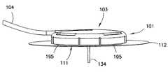
以下に記載する本発明の例示的な実施形態は、軟性カテーテルを皮膚内へ挿入する新規な手段を提供する。詳細には、本発明の例示的な実施形態は、導入針142および軟性カテーテル134を皮膚内へ挿入し、次いで図2、図3、図10、および図14に示すように、注入セット101のベース111内にばね部材171を格納する挿入器121を提供し、それによって低プロファイルの注入セットを提供する。 The exemplary embodiments of the invention described below provide a novel means of inserting a flexible catheter into the skin. Specifically, the exemplary embodiment of the present invention inserts
注入セットのベース111は、図2および図3に示すように、挿入部位で注入セットを皮膚表面に固定するために、皮膚に固定する接着層112を備えることが好ましい。接着層112により、ベースは皮膚表面に対して正しい位置に確実に留まることができ、挿入中に皮膚を確実に固定して、皮膚表面の傷口を広げるリスクを低減させながら導入針の挿入をさらに助けることができる。図4、図10、および図11に示すように、ベース111は平面113を有し、平面113内に開口114が設けられ、開口114をカテーテル134および導入針142が通過する。図4に示すように、壁115が平面113の外縁部から上方へ延び、その結果、平面および壁115によって空胴116が画定される。 The
挿入器121は、図2、図4、および図10に示すように、ベース111に回転可能に接続された筐体またはダイヤル123と、ダイヤル123のベース122から上方へ延びるダイヤルポスト124と、ダイヤルポスト124に可動式に接続されたノブ125とを含む。ダイヤル123は、図2および図4に示すように、実質上切頭円錐形の形状を有する。ダイヤル123の壁126は、ダイヤルベース122から下方および外側へ延び、ダイヤルポスト124は、ダイヤルベース122から上方へ、ダイヤルベース122に対して実質上垂直に延びる。ダイヤルポスト124は、図12に示すように、互いから隔置された3つの実質上弧状の部材181、182、および183をその上端部に含むことが好ましい。ダイヤルベース122から下方へは、第1のアーム191および第2のアーム193が延び、ダイヤル壁126内に配置される。図6に示すように、第1のアーム191および第2のアーム193上には、それぞれ第1の肩部192および第2の肩部194が形成される。図4〜6に示すように、第1のアーム191と第2のアーム193との間には、スロット197および198が形成される。スロット197および198により、カテーテルハブ131を下方へ動かすことが可能になる。図11および図15に示すように、アーム191および193に接続されたフック117および118が、ベース111によって受容される。フック117および118は、図11に示すように、ベース111の下面132に係合し、カテーテル134の挿入前にダイヤル121が引き込まれるのを防止する。 As shown in FIGS. 2, 4, and 10, the
挿入器ノブ125は、図4に示す第1の位置、すなわち上位の位置と、図12に示す第2の位置、すなわち下位の位置との間を動くことができる。挿入器ノブ125は、導入針プランジャ141の端部にしっかりと固定される。図4に示すように、ノブ125が第1の位置にあるとき、導入針142はダイヤル123内に配置されている。図10に示すように、ノブ125が第2の位置にあるとき、導入針142はダイヤル123の外側に露出される。 The
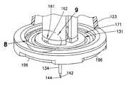
カテーテルハブ131は最初、図4および図5に示すように、ダイヤル123の内側の第1の位置に配置されている。カテーテルハブ131は、第1の接続アーム136および第2の接続アーム137によって接続された内側リング133および外側リング135を有する。カテーテルハブ131が第1の位置にあるとき、第1の接続アーム136および第2の接続アーム137は、図5に示すように、ダイヤルのアーム191および193の肩部192および194上に位置し、それによってカテーテルハブ131が下方(ベース111の方)へ動くのを防止する。カテーテルハブ131の内側リング133から、軟性カテーテル134が下方へ延びる。図4に示すように、カテーテルハブ131の内側リング133内に開口138が配置され、導入針142が開口138を貫通することが可能になる。図4および図14に示すように、カテーテルハブ131の内側リング133内に形成された凹部の内側には、隔壁172が配置される。 The
図4に示すように、ダイヤル123内にばね部材171が配置される。ばね部材171の第1の端部173は、カテーテルハブ131に接続される。ばね部材171の第2の端部174は、ベース111に接続される。ばね部材171は、螺旋状の引っ張りばねであることが好ましく、したがって、第1の端部173から第2の端部174へ延びるばね部材のコイルは、次に進むたびに直径がより大きくなる。螺旋状のばねは、通常は実質上円錐形状の圧縮ばねである。螺旋状のばねが圧縮を受けると、コイルは互いに押し付けられるのではなく互いの中に入り込み、したがって移動距離をより長くすることができ、圧縮された構成でさらに小型にすることができる。図4に示すように、最初、ばね部材171には張力がかかっており、カテーテルハブ131はアーム191および193の肩部192および194上に位置し、カテーテルハブ131が下方へ動くのを防止する。ばね部材171は、解放されると折り畳まれ、それによってカテーテル134および導入針142を挿入部位内へ引き込む。図14に示すように、ばね部材171は折り重なって低いプロファイルを有する実質上円板形状の部材を形成し、この部材がベース111内の空胴116内に実質上完全に受容される。 As shown in FIG. 4, a
導入針プランジャ141は、図4に示すように、第1の端部143および第2の端部145を有する。第1の端部143は、ノブ125にしっかりと接続され、その結果、ノブはプランジャ141とともに動く。導入針142は、第2の端部145にしっかりと接続され、その結果、導入器はプランジャ141の動きとともに動く。プランジャ141は、ダイヤルポスト124内で動かすとダイヤル123の外部で動き、アーム191および193内で動かすとダイヤル123内で動く。プランジャ141は、図4に示す第1の位置から図12に示す第2の位置へ動き、また第1の位置に戻ることができる。第1のプランジャアーム146および第2のプランジャアーム147は、図5、図6、図15、および図16に示すように、カテーテルハブ131の下面132に係合するフック148および149を有する。カテーテルハブ131の外周内の凹部185および186により、カテーテル134を挿入した後にプランジャ141をカテーテルハブから切り離すことが可能になる。 As shown in FIG. 4, the
導入針142は隔壁172およびカテーテル134を貫通しており、その結果、図7、図10、および図11に示すように、カテーテルハブ131が第2の位置につくと、導入針の端部144がカテーテル134の外側に露出される。導入針端部142の端部144は鋭く、所望のカテーテル挿入点で皮膚に容易に穴を開けることができる。プランジャ141が第1の位置にあるとき(図4)、導入針142はダイヤル123の外側に露出されない。プランジャ141が第2の位置にあるとき(図12)、導入針142はダイヤル123およびベース111の外部に露出され、その結果、所望のカテーテル挿入点で皮膚に穴を開けることができる。 The
図4に示すように、ベース111内にロッキング部材161が回転可能に配置される。図8、図9、および図11に示すように、ベース111に接続されたスナップアーム106および107がフック108および109を有し、フック108および109は、図9に示すように、ロッキング部材161の凹部162内に受容され、カテーテル134の挿入前にロッキング部材161がベース111に対して回転するのを防止する。スナップアーム106および107は、挿入中にカテーテルハブ131によって下方へ動かされ、その結果、図8および図9に示すように、フック108および109が凹部162から出て、それによってロッキング部材161を回転させることが可能になる。ロッキング部材161は、図14に示すように、カテーテル134の挿入後にカテーテルハブ131の上へ回転する張出し164および165を有し、それによってカテーテルハブ131をベース111にロックする。 As shown in FIG. 4, a locking
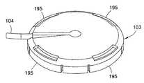
図1〜3に示すように、コネクタ103は複数の可撓性のアーム195を有し、可撓性のアーム195は、ベース111の外面内の対応する凹部196に係合するように適合される。コネクタ103からは管材104が延びており、ポンプに接続するように適合される。管材104は、コネクタ103から下方へ延びる貫通部材または鋭利部材(図示せず)に接続され、管材104と貫通部材との間に流体経路が形成される。貫通部材は、図3に示すように、コネクタ103がベース111に接続されたときに隔壁172を貫通するように適合され、それによって管材104とカテーテル134との間に流体経路を形成する。 As shown in FIGS. 1-3, the
組立ておよび動作
図2は、使用者によって受容されたベース111および挿入器121の斜視図である。挿入器121のフック117および118は、図11に示すように、ベース111の下面132に係合し、それによって挿入器121がベースから取り外されるのを防止する。ノブ125は、図2に示すように、第1の位置、すなわち上位の位置にあり、その結果、カテーテル134および導入針142は、図2に示すように、ダイヤル本体123内に実質上完全に配置され、それによって偶発的に導入針で刺すことを実質上防止する。カテーテル134が挿入されていないため、コネクタ103(図1)はまだベース111に接続されていない。図4に示すように、ばね部材171には張力がかかっている。Assembly and Operation FIG. 2 is a perspective view of the
カテーテル134を挿入する前に、裏当て(図示せず)が取り外されて接着層112が露出し、その結果、ベース111を所望のカテーテル挿入部位で皮膚表面に接着することができる。カテーテル挿入前、カテーテルハブ131はダイヤルアーム191および193の肩部192および194上に位置し、それによってカテーテルハブ131が下方へ動くのを防止する。カテーテル173を挿入するには、ダイヤル123を時計回りに回転させる。接着層112は、ダイヤル123が回転したときにベース111の動きに耐えるように、回転に逆らう力を提供する。ダイヤル123が回転すると、ダイヤルアーム191および193が回転し、それによって、図6に示すように、ダイヤルアーム191および193の肩部192および194がカテーテルハブ131から切り離される。ここでカテーテルハブアーム136および137は、ベースアーム191および193間でスロット197および198と位置合わせされており、その結果、引き伸ばされたばね部材171内に蓄積されたエネルギーにより、カテーテルハブ131が下方(すなわち、ベース111の方)へ引っ張られる。スロット197および198は、カテーテルハブ131をベース111の方へ下方に動かすことによって案内する。カテーテル134はカテーテルハブ131にしっかりと接続されており、その結果、カテーテル134はカテーテルハブ131とともに下方へ引っ張られる。プランジャフック148および149はカテーテルハブ131に係合しており、その結果、プランジャ141にしっかりと接続された導入針142もまた、カテーテルハブ131とともに下方へ引っ張られる。さらに、プランジャ141の第1の端部143に接続されたノブ125は、図10に示すように、ダイヤルポスト124に沿って下方へ引っ張られる。ノブ125が第2の位置、すなわち下位の位置に動くことで、導入針142およびカテーテル134が挿入されたことを使用者に指し示す。 Prior to insertion of the
導入針142およびカテーテル134の挿入前、ベース111のスナップアーム106および107のフック108および109はロッキング部材161内の凹部162内に受容されており、それによってロッキング部材161が動くのを防止する。図11に示すように、ロッキング部材161から放射状に内方へ延びるタブ178および179がダイヤル123のフック117および118に係合しており、それによって、カテーテル134および導入針142が挿入される前に、ダイヤルがさらに回転して引き込まれるのを防止する。ばね部材171がカテーテルハブ131をベース111内の空胴116内へ引き込むと、図8および図9に示すように、カテーテルハブ131はベーススナップアーム106および107に係合して下方へ押す。ベーススナップアーム106および107が下方へ動くと、フック108および109がロッキング部材161内の凹部162から出て、それによってロッキング部材161およびダイヤル123を回転させることが可能になる。ここでカテーテル134および導入針142は、図10および図11に示すように、挿入部位内に挿入されている。 Prior to insertion of
このとき、ダイヤル123を時計回りにさらに回転させることができる。ダイヤルフック117および118が回転すると、ロッキング部材のタブ178および179が回転する。ロッキング部材161が回転すると、図9および図11に示すように、ベーススナップアーム106および107がロッキング部材の外面上の傾斜175および176に沿って摺動してロック凹部177および180に入る。また、ロッキング部材161が回転すると、図12に示すように、ロッキング部材の張出し164および165がカテーテルハブ131の上へ回転し、それによってカテーテルハブ131をベース111へロックする。 At this time, the
ダイヤル123が回転すると、図11に示すように、フック117および118が動いてベース111内の凹部185および186に係合する。ダイヤル123の回転によってプランジャフック148および149も回転し、カテーテルハブ131内の凹部154および155に係合する。したがって、図14および図15に示すように、ダイヤル123およびプランジャ141を含む挿入器121をベース111から取り外すことができる。図14に示すように、ばね部材171、カテーテルハブ131、およびロッキング部材161はベース111内に留まり、その結果、カテーテル134は挿入部位内に挿入されたままであり、導入針142は挿入部位から引き抜かれる。 When the
このとき、図14に示すように、カテーテルハブ131内の隔壁172は露出されている。ダイヤル123が回転してベース111から取り外された後、軟性カテーテル134は皮膚の下へ挿入されたまま実質上垂直の位置に留まり、すなわち軟性カテーテル134は、ダイヤル123の回転運動とともに屈曲しない。したがって、導入針142が流体経路の一部ではなくなるため、隔壁172に穴を開けることで軟性カテーテル134への直接的な流体経路が設けられる。 At this time, as shown in FIG. 14, the
このとき、流体コネクタ103上の貫通部材または鋭利部材(図示せず)は、隔壁172を貫通することができ、それによってカテーテル134と管材104との間に流体接続をもたらすことができる。使用者は、コネクタ103を注入セットベース111に接続する前に、コネクタ103に呼び水をすることができる。コネクタ103の可撓性のアーム195は、ベース111内の凹部196に係合して、コネクタ103をベース111に着脱可能に接続する。ここで注入セット101は、図1および図3に示すように、インシュリンの注入を開始する準備ができている。可撓性のアーム195とベース凹部196を着脱することによって、任意の時点でコネクタ103を取り外し、また再び注入セットベース111に取り付けることができる。隔壁172は、貫通部材が隔壁172から取り外されると無菌障壁を提供し、ベース111内のロッキング部材161によって固定されたカテーテルハブ131内に位置する隔壁172に貫通部材を再び挿入することによって、流体接続が再び確立される。 At this time, a penetrating member or sharp member (not shown) on the
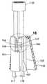
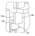
取り外された挿入器121のノブ125は、図15に示すように、第1の位置、すなわち上位の位置に戻り、それによってプランジャ141を持ち上げ、導入針141を筐体またはダイヤル123内の保護位置へ引き込む。図4、図15、および図16に示すように、ノブ125は、プランジャ141内の凹部157がダイヤル123のフック158に係合するまで持ち上げられる。ダイヤルフック158はプランジャ凹部157に係合し、それによってプランジャ141が下方へ動くのを防止し、偶発的に導入針で刺すことを実質上防止する。 As shown in FIG. 15, the
上記の例示的な実施形態は、皮下注射または皮内注射で使用するために適合することもできる。さらに、貫通部材197および隔壁172以外にも、流体接続を維持する異なる方法が可能である。たとえば、摺動ガスケットシールを使用することができる。代替的方法を使用して、カテーテルおよび導入器を挿入することもできる。たとえば、角のある針を皮膚に接触させて水平に動かすことで、皮膚の皮下層または皮内層に入れることができる。コネクタをベースに接続する代替的方法を使用して、コネクタの着脱を容易にすることもできる。図4および図16に示すように、プランジャ141を上方へ引っ張ってダイヤルフック158に係合させることを容易にするには、凹部157の上でプランジャ141上に傾斜表面159を設けることが好ましい。あるいは、導入針142は、挿入器121とともにベースから引き抜くのではなく、カテーテル134を挿入した後に挿入部位から引き抜いてベース111内に格納することもできる。 The exemplary embodiments described above can also be adapted for use with subcutaneous or intradermal injection. Further, besides the penetrating
上記の例示的な実施形態は注入セットであるが、本発明の原理はまた、パッチポンプ(一体化されたリザーバおよびポンプ機構を有する自立型の注入デバイス)ならびに他のタイプの医療用注入および注射デバイスにも適用できることが、当業者には明らかであろう。 While the exemplary embodiment described above is an infusion set, the principles of the present invention are also applicable to patch pumps (self-supporting infusion devices having an integrated reservoir and pump mechanism) and other types of medical infusions and injections. It will be apparent to those skilled in the art that it can also be applied to devices.
上記の実施形態および利点は、例示のみを目的とするものであり、本発明の範囲を限定すると解釈されるものではない。本発明の例示的な実施形態の説明は例示であり、本発明の範囲を限定するものではない。様々な修正形態、代替形態、および変形形態が当業者には明らかであり、添付の特許請求の範囲およびその等価物の範囲内に入るものとする。 The above-described embodiments and advantages are for illustrative purposes only and are not to be construed as limiting the scope of the invention. The descriptions of exemplary embodiments of the invention are exemplary and are not intended to limit the scope of the invention. Various modifications, alternatives, and variations will be apparent to those skilled in the art and are intended to be within the scope of the appended claims and their equivalents.
Claims (8)
Translated fromJapanese前記ベースに着脱可能に接続された挿入器と、
前記挿入器内に実質上完全に配置された第1のカテーテル位置から、自由端部が前記ベースの外部に配置される第2のカテーテル位置へ動くことができるカテーテルと、
前記カテーテル内に位置し、前記挿入器内に実質上完全に配置された第1の導入針位置と、自由端部が前記ベースの外部に配置される第2の導入針位置との間を、前記カテーテルとともに動くことができる導入針と、
前記カテーテルを前記第1のカテーテル位置から前記第2のカテーテル位置へ動かし、前記導入針を前記第1の導入針位置から前記第2の導入針位置へ動かして、前記カテーテルの挿入を容易にするばね部材であって、前記カテーテルが前記第2のカテーテル位置にあるとき、前記ベース内に実質上完全に配置されるばね部材と
を備え、
前記ばね部材は、螺旋状の引っ張りばねであり、第1の端部から第2の端部へ延びるばね部材のコイルは次に進むたびに直径がより大きくなる、
ことを特徴とする注入セット。Base and
An inserter detachably connected to the base;
A catheter capable of moving from a first catheter position substantially completely disposed within the inserter to a second catheter position disposed free of the base;
Between a first introducer needle position located within the catheter and substantially completely disposed within the inserter; and a second introducer needle position with a free end disposed outside the base; An introducer needle movable with the catheter;
Moving the catheter from the first catheter position to the second catheter position and moving the introducer needle from the first introducer needle position to the second introducer needle position to facilitate insertion of the catheter A spring member, wherein the spring member is substantially completely disposed within the base when the catheter is in the second catheter position;
The spring member is a helical tension spring, and the coil of the spring member extending from the first end to the second end has a larger diameter each time it proceeds.
An infusion set characterized by that.
ことを特徴とする請求項1に記載の注入セット。The infusion set according to claim 1, wherein the spring member is a spiral spring.
ことを特徴とする請求項1に記載の注入セット。The infusion set according to claim 1, wherein the spring member is actuated by rotating the inserter relative to the base.
ことを特徴とする請求項1に記載の注入セット。The infusion set of claim 1, wherein the inserter is removable from the base by rotating the inserter relative to the base when the catheter is in the second position. .
ことを特徴とする請求項4に記載の注入セット。5. An infusion set according to claim 4, wherein the introducer needle is removable from the base with the inserter and is substantially completely disposed within the removed inserter.
ことを特徴とする請求項1に記載の注入セット。The infusion set according to claim 1, wherein the introducer needle and the catheter enter the skin surface at an angle substantially perpendicular to the skin surface.
ことを特徴とする請求項1に記載の注入セット。The infusion set of claim 1, wherein a septum disposed within the base is exposed by removing the inserter to receive a fluid connector.
ことを特徴とする請求項4に記載の注入セット。5. The infusion set of claim 4, wherein the catheter is locked to the base when the inserter is rotated and removed from the base.
Applications Claiming Priority (3)
| Application Number | Priority Date | Filing Date | Title |
|---|---|---|---|
| US201161448927P | 2011-03-03 | 2011-03-03 | |
| US61/448,927 | 2011-03-03 | ||
| PCT/US2012/000076WO2012141759A1 (en) | 2011-03-03 | 2012-02-08 | Compact spring inserter for drug delivery infusion set |
Related Child Applications (1)
| Application Number | Title | Priority Date | Filing Date |
|---|---|---|---|
| JP2016160607ADivisionJP6348548B2 (en) | 2011-03-03 | 2016-08-18 | Small spring inserter for drug delivery infusion set |
Publications (2)
| Publication Number | Publication Date |
|---|---|
| JP2014511248A JP2014511248A (en) | 2014-05-15 |
| JP5992932B2true JP5992932B2 (en) | 2016-09-14 |
Family
ID=47009623
Family Applications (2)
| Application Number | Title | Priority Date | Filing Date |
|---|---|---|---|
| JP2013556616AActiveJP5992932B2 (en) | 2011-03-03 | 2012-02-08 | Small spring inserter for drug delivery infusion set |
| JP2016160607AActiveJP6348548B2 (en) | 2011-03-03 | 2016-08-18 | Small spring inserter for drug delivery infusion set |
Family Applications After (1)
| Application Number | Title | Priority Date | Filing Date |
|---|---|---|---|
| JP2016160607AActiveJP6348548B2 (en) | 2011-03-03 | 2016-08-18 | Small spring inserter for drug delivery infusion set |
Country Status (7)
| Country | Link |
|---|---|
| US (1) | US9433757B2 (en) |
| EP (1) | EP2680898B1 (en) |
| JP (2) | JP5992932B2 (en) |
| CN (1) | CN203694219U (en) |
| CA (1) | CA2828391C (en) |
| ES (1) | ES2880256T3 (en) |
| WO (1) | WO2012141759A1 (en) |
Families Citing this family (43)
| Publication number | Priority date | Publication date | Assignee | Title |
|---|---|---|---|---|
| US8919452B2 (en) | 2010-11-08 | 2014-12-30 | Baker Hughes Incorporated | Casing spears and related systems and methods |
| US8998851B2 (en) | 2011-02-09 | 2015-04-07 | Becton, Dickinson And Company | Compact spring inserter for drug deliver infusion set |
| CA2826094C (en) | 2011-02-09 | 2020-11-10 | Becton, Dickinson And Company | Subcutaneous infusion device |
| EP2691144B1 (en) | 2011-03-30 | 2017-11-15 | Unomedical A/S | Subcutaneous inserter device |
| CA2858199C (en) | 2011-12-07 | 2020-05-12 | Becton, Dickinson And Company | Infusion device with releasable fluid connector |
| ES2666386T3 (en) | 2011-12-07 | 2018-05-04 | Becton, Dickinson And Company | Needle protection sets and infusion devices for use with them |
| WO2013151044A1 (en)* | 2012-04-05 | 2013-10-10 | 久光製薬株式会社 | Puncture device and method for manufacturing same |
| USD756504S1 (en)* | 2012-12-07 | 2016-05-17 | Becton, Dickinson And Company | Infusion set base |
| USD747459S1 (en)* | 2012-12-07 | 2016-01-12 | Becton, Dickinson And Company | Infusion set assembly |
| USD747458S1 (en)* | 2012-12-07 | 2016-01-12 | Becton, Dickinson And Company | Infusion set insertion needle assembly |
| USD747456S1 (en)* | 2012-12-07 | 2016-01-12 | Becton, Dickinson And Company | Infusion set assembly |
| USD754843S1 (en)* | 2012-12-07 | 2016-04-26 | Becton, Dickinson And Company | Infusion set assembly |
| USD754842S1 (en)* | 2012-12-07 | 2016-04-26 | Becton, Dickinson And Company | Infusion set needle guard |
| USD747457S1 (en)* | 2012-12-07 | 2016-01-12 | Becton, Dickinson And Company | Infusion set needle guard |
| CN104955517B (en)* | 2012-12-21 | 2017-09-26 | 久光制药株式会社 | Applicator |
| US20140323989A1 (en)* | 2013-04-24 | 2014-10-30 | Calibra Medical, Inc. | Wearable infusion device with low profile handle |
| JP6215343B2 (en) | 2013-11-05 | 2017-10-18 | 久光製薬株式会社 | applicator |
| CN103654969B (en)* | 2013-12-24 | 2015-12-30 | 湖州美奇医疗器械有限公司 | A kind of medical treatment helps pin device |
| EP3345648A4 (en) | 2015-09-02 | 2019-04-17 | Hisamitsu Pharmaceutical Co., Inc. | APPLICATOR |
| USD806232S1 (en) | 2016-01-21 | 2017-12-26 | Becton, Dickinson And Company | Drug delivery device with insertion mechanism |
| USD805631S1 (en) | 2016-01-21 | 2017-12-19 | Becton, Dickinson And Company | Drug delivery device with insertion mechanism button safety |
| USD829889S1 (en) | 2016-01-21 | 2018-10-02 | Becton, Dickinson And Company | Wearable drug delivery device with adhesive |
| USD829894S1 (en) | 2016-01-21 | 2018-10-02 | Becton, Dickinson And Company | Wearable drug delivery device baseplate |
| USD830537S1 (en) | 2016-01-21 | 2018-10-09 | Becton, Dickinson And Company | Wearable drug delivery device with adhesive and liner |
| USD830547S1 (en) | 2016-01-21 | 2018-10-09 | Becton, Dickinson And Company | Adhesive liner for wearable drug delivery device |
| USD857191S1 (en) | 2016-01-21 | 2019-08-20 | Becton, Dickinson And Company | Wearable drug delivery device |
| WO2018022433A1 (en) | 2016-07-27 | 2018-02-01 | Becton, Dickinson And Company | Infusion device with stabilizer member |
| KR101928297B1 (en)* | 2016-09-08 | 2018-12-12 | 이오플로우(주) | Medical fluid delivery device |
| KR20190088073A (en) | 2016-12-16 | 2019-07-25 | 소렌토 쎄라퓨틱스, 인코포레이티드 | Attachment band for fluid delivery device and method of using same |
| US11344709B2 (en) | 2016-12-16 | 2022-05-31 | Sorrento Therapeutics, Inc. | Fluid delivery apparatus having a controller assembly and method of use |
| CA3046799A1 (en) | 2016-12-16 | 2018-06-21 | Sorrento Therapeutics, Inc. | Fluid delivery apparatus and method of assembly |
| KR20190088077A (en) | 2016-12-16 | 2019-07-25 | 소렌토 쎄라퓨틱스, 인코포레이티드 | Suitable dosing methods for treating migraine or military headaches |
| EP3554620A4 (en) | 2016-12-16 | 2020-07-15 | Sorrento Therapeutics, Inc. | Application device for a fluid delivery apparatus and method of use |
| KR20230031372A (en) | 2016-12-16 | 2023-03-07 | 소렌토 쎄라퓨틱스, 인코포레이티드 | Fluid delivery apparatus having a gas extraction device and method of use |
| CA3126999A1 (en) | 2019-02-22 | 2020-08-27 | Deka Products Limited Partnership | Infusion set and inserter assembly systems and methods |
| CA3180472A1 (en)* | 2020-05-28 | 2021-12-02 | Eli Lilly And Company | Shift-head inserter device with automatic insertion and retraction |
| US20230310740A1 (en)* | 2020-09-08 | 2023-10-05 | Medtrum Technologies Inc. | Infusion needle structure of drug infusion device |
| AU2022206656A1 (en)* | 2021-01-05 | 2023-07-20 | Becton, Dickinson And Company | Needle hub for drug delivery device |
| JP2023019160A (en)* | 2021-07-28 | 2023-02-09 | テルモ株式会社 | lancing device |
| USD1013864S1 (en) | 2021-08-26 | 2024-02-06 | Deka Products Limited Partnership | Fluid administration apparatus assembly |
| USD1043976S1 (en) | 2022-08-26 | 2024-09-24 | Deka Products Limited Partnership | Fluid transfer connector |
| USD1090862S1 (en) | 2022-08-26 | 2025-08-26 | Deka Products Limited Partnership | Adhering assembly for medical devices and the like |
| USD1057941S1 (en) | 2022-08-26 | 2025-01-14 | Deka Products Limited Partnership | Patient care assembly component |
Family Cites Families (15)
| Publication number | Priority date | Publication date | Assignee | Title |
|---|---|---|---|---|
| EP1383560B2 (en)* | 2001-04-06 | 2023-04-26 | F. Hoffmann-La Roche AG | Infusion set |
| US6830562B2 (en) | 2001-09-27 | 2004-12-14 | Unomedical A/S | Injector device for placing a subcutaneous infusion set |
| US7128727B2 (en) | 2002-09-30 | 2006-10-31 | Flaherty J Christopher | Components and methods for patient infusion device |
| US8167841B2 (en) | 2005-01-24 | 2012-05-01 | Novo Nordisk A/S | Transcutaneous device assembly |
| US7699833B2 (en)* | 2005-05-06 | 2010-04-20 | Moberg Sheldon B | Pump assembly and method for infusion device |
| EP1762259B2 (en) | 2005-09-12 | 2025-01-01 | Unomedical A/S | Inserter for an infusion set with a first and second spring units |
| IL178557A0 (en)* | 2005-10-19 | 2007-02-11 | Animas Corp | Safety infusion set |
| US20070191772A1 (en)* | 2006-02-16 | 2007-08-16 | Animas Corporation | Straight insertion safety infusion set |
| EP2032188A1 (en)* | 2006-06-06 | 2009-03-11 | Novo Nordisk A/S | Assembly comprising skin-mountable device and packaging therefore |
| US7682338B2 (en) | 2006-08-23 | 2010-03-23 | Medtronic Minimed, Inc. | Infusion medium delivery system, device and method with needle inserter and needle inserter device and method |
| DK1970083T3 (en)* | 2007-03-14 | 2017-09-11 | Hoffmann La Roche | Insertion device for an insertion head, especially for an infusion set |
| US20100152674A1 (en)* | 2007-04-30 | 2010-06-17 | Medtronic Minimed, Inc | Needle inserting and fluid flow connection for infusion medium delivery system |
| AU2009299888B2 (en)* | 2008-10-01 | 2012-07-05 | Shl Group Ab | Medicament delivery device powered by volute spring |
| CA2749528C (en)* | 2009-01-21 | 2020-08-18 | Becton, Dickinson And Company | Infusion set |
| EP2272553A1 (en)* | 2009-06-29 | 2011-01-12 | Unomedical A/S | Inserter Assembly |
- 2012
- 2012-02-08JPJP2013556616Apatent/JP5992932B2/enactiveActive
- 2012-02-08USUS14/002,210patent/US9433757B2/enactiveActive
- 2012-02-08ESES12770720Tpatent/ES2880256T3/enactiveActive
- 2012-02-08CNCN201290000412.XUpatent/CN203694219U/ennot_activeExpired - Lifetime
- 2012-02-08CACA2828391Apatent/CA2828391C/enactiveActive
- 2012-02-08WOPCT/US2012/000076patent/WO2012141759A1/enactiveApplication Filing
- 2012-02-08EPEP12770720.6Apatent/EP2680898B1/enactiveActive
- 2016
- 2016-08-18JPJP2016160607Apatent/JP6348548B2/enactiveActive
Also Published As
| Publication number | Publication date |
|---|---|
| EP2680898A1 (en) | 2014-01-08 |
| JP2014511248A (en) | 2014-05-15 |
| CN203694219U (en) | 2014-07-09 |
| CA2828391A1 (en) | 2012-10-18 |
| WO2012141759A1 (en) | 2012-10-18 |
| CA2828391C (en) | 2019-03-05 |
| US20140039458A1 (en) | 2014-02-06 |
| US9433757B2 (en) | 2016-09-06 |
| EP2680898B1 (en) | 2021-05-26 |
| JP6348548B2 (en) | 2018-06-27 |
| JP2016190124A (en) | 2016-11-10 |
| EP2680898A4 (en) | 2014-10-01 |
| ES2880256T3 (en) | 2021-11-24 |
Similar Documents
| Publication | Publication Date | Title |
|---|---|---|
| JP5992932B2 (en) | Small spring inserter for drug delivery infusion set | |
| US12023465B2 (en) | Self-contained spring inserter for drug delivery infusion device | |
| US10188836B2 (en) | Folding inserter for drug delivery infusion set | |
| EP2968891B1 (en) | Automatic angled infusion set assembly | |
| JP6066928B2 (en) | Self-retracting inserter for drug delivery infusion set | |
| CA2902487C (en) | Angled inserter for drug infusion | |
| CA2826203C (en) | Self-contained torsion spring inserter for drug delivery infusion set |
Legal Events
| Date | Code | Title | Description |
|---|---|---|---|
| A621 | Written request for application examination | Free format text:JAPANESE INTERMEDIATE CODE: A621 Effective date:20150202 | |
| A131 | Notification of reasons for refusal | Free format text:JAPANESE INTERMEDIATE CODE: A131 Effective date:20151201 | |
| A521 | Request for written amendment filed | Free format text:JAPANESE INTERMEDIATE CODE: A523 Effective date:20160301 | |
| TRDD | Decision of grant or rejection written | ||
| A01 | Written decision to grant a patent or to grant a registration (utility model) | Free format text:JAPANESE INTERMEDIATE CODE: A01 Effective date:20160719 | |
| A61 | First payment of annual fees (during grant procedure) | Free format text:JAPANESE INTERMEDIATE CODE: A61 Effective date:20160818 | |
| R150 | Certificate of patent or registration of utility model | Ref document number:5992932 Country of ref document:JP Free format text:JAPANESE INTERMEDIATE CODE: R150 | |
| R250 | Receipt of annual fees | Free format text:JAPANESE INTERMEDIATE CODE: R250 | |
| R250 | Receipt of annual fees | Free format text:JAPANESE INTERMEDIATE CODE: R250 | |
| R250 | Receipt of annual fees | Free format text:JAPANESE INTERMEDIATE CODE: R250 | |
| R250 | Receipt of annual fees | Free format text:JAPANESE INTERMEDIATE CODE: R250 | |
| R250 | Receipt of annual fees | Free format text:JAPANESE INTERMEDIATE CODE: R250 |