JP5992425B2 - Surgical instrument with modular shaft and end effector - Google Patents
Surgical instrument with modular shaft and end effectorDownload PDFInfo
- Publication number
- JP5992425B2 JP5992425B2JP2013537830AJP2013537830AJP5992425B2JP 5992425 B2JP5992425 B2JP 5992425B2JP 2013537830 AJP2013537830 AJP 2013537830AJP 2013537830 AJP2013537830 AJP 2013537830AJP 5992425 B2JP5992425 B2JP 5992425B2
- Authority
- JP
- Japan
- Prior art keywords
- assembly
- end effector
- shaft
- handle assembly
- surgical instrument
- Prior art date
- Legal status (The legal status is an assumption and is not a legal conclusion. Google has not performed a legal analysis and makes no representation as to the accuracy of the status listed.)
- Active
Links
- 239000012636effectorSubstances0.000titleclaimsdescription340
- 230000005540biological transmissionEffects0.000claimsdescription111
- 230000000295complement effectEffects0.000claimsdescription20
- 238000007373indentationMethods0.000claimsdescription16
- 230000008878couplingEffects0.000description115
- 238000010168coupling processMethods0.000description115
- 238000005859coupling reactionMethods0.000description115
- 230000007246mechanismEffects0.000description101
- 238000000034methodMethods0.000description48
- 238000005520cutting processMethods0.000description26
- 239000004020conductorSubstances0.000description17
- 238000007789sealingMethods0.000description13
- 238000001356surgical procedureMethods0.000description11
- 230000002093peripheral effectEffects0.000description10
- 230000000712assemblyEffects0.000description7
- 238000000429assemblyMethods0.000description7
- 230000005693optoelectronicsEffects0.000description7
- 238000005516engineering processMethods0.000description6
- 239000012530fluidSubstances0.000description6
- 238000003780insertionMethods0.000description5
- 230000037431insertionEffects0.000description5
- 238000002604ultrasonographyMethods0.000description5
- 238000012986modificationMethods0.000description4
- 230000004048modificationEffects0.000description4
- 239000004033plasticSubstances0.000description4
- 238000004140cleaningMethods0.000description3
- 230000005855radiationEffects0.000description3
- 102000008186CollagenHuman genes0.000description2
- 108010035532CollagenProteins0.000description2
- 230000001112coagulating effectEffects0.000description2
- 229920001436collagenPolymers0.000description2
- 239000003814drugSubstances0.000description2
- 229940079593drugDrugs0.000description2
- 238000002651drug therapyMethods0.000description2
- 230000001747exhibiting effectEffects0.000description2
- 238000000605extractionMethods0.000description2
- 238000001415gene therapyMethods0.000description2
- 238000009413insulationMethods0.000description2
- 238000004519manufacturing processMethods0.000description2
- 239000000463materialSubstances0.000description2
- 239000000203mixtureSubstances0.000description2
- 229920000642polymerPolymers0.000description2
- 239000000523sampleSubstances0.000description2
- 125000006850spacer groupChemical group0.000description2
- 238000004659sterilization and disinfectionMethods0.000description2
- 241000894006BacteriaSpecies0.000description1
- UBDOMNPXQKOPRG-UHFFFAOYSA-NCCCCCNC1OC1Chemical compoundCCCCCNC1OC1UBDOMNPXQKOPRG-UHFFFAOYSA-N0.000description1
- RYGMFSIKBFXOCR-UHFFFAOYSA-NCopperChemical group[Cu]RYGMFSIKBFXOCR-UHFFFAOYSA-N0.000description1
- IAYPIBMASNFSPL-UHFFFAOYSA-NEthylene oxideChemical compoundC1CO1IAYPIBMASNFSPL-UHFFFAOYSA-N0.000description1
- 229920000106Liquid crystal polymerPolymers0.000description1
- 239000004977Liquid-crystal polymers (LCPs)Substances0.000description1
- WCUXLLCKKVVCTQ-UHFFFAOYSA-MPotassium chlorideChemical compound[Cl-].[K+]WCUXLLCKKVVCTQ-UHFFFAOYSA-M0.000description1
- 239000004775TyvekSubstances0.000description1
- 229920000690TyvekPolymers0.000description1
- 239000000919ceramicSubstances0.000description1
- 230000015271coagulationEffects0.000description1
- 238000005345coagulationMethods0.000description1
- 230000006835compressionEffects0.000description1
- 238000007906compressionMethods0.000description1
- 238000010276constructionMethods0.000description1
- 238000001514detection methodMethods0.000description1
- 238000009792diffusion processMethods0.000description1
- 230000000694effectsEffects0.000description1
- 239000000835fiberSubstances0.000description1
- 238000010438heat treatmentMethods0.000description1
- 230000006698inductionEffects0.000description1
- 239000011810insulating materialSubstances0.000description1
- 238000002357laparoscopic surgeryMethods0.000description1
- 239000002184metalSubstances0.000description1
- 229910052751metalInorganic materials0.000description1
- 239000007769metal materialSubstances0.000description1
- 239000012811non-conductive materialSubstances0.000description1
- 230000010355oscillationEffects0.000description1
- 239000004417polycarbonateSubstances0.000description1
- 229920000515polycarbonatePolymers0.000description1
- 230000008569processEffects0.000description1
- 108090000623proteins and genesProteins0.000description1
- 102000004169proteins and genesHuman genes0.000description1
- 238000011084recoveryMethods0.000description1
- 230000000452restraining effectEffects0.000description1
- 238000007711solidificationMethods0.000description1
- 230000008023solidificationEffects0.000description1
- 230000001954sterilising effectEffects0.000description1
- 230000001225therapeutic effectEffects0.000description1
- XLYOFNOQVPJJNP-UHFFFAOYSA-NwaterChemical compoundOXLYOFNOQVPJJNP-UHFFFAOYSA-N0.000description1
Images


Classifications
- A—HUMAN NECESSITIES
- A61—MEDICAL OR VETERINARY SCIENCE; HYGIENE
- A61B—DIAGNOSIS; SURGERY; IDENTIFICATION
- A61B17/00—Surgical instruments, devices or methods
- A61B17/32—Surgical cutting instruments
- A61B17/320068—Surgical cutting instruments using mechanical vibrations, e.g. ultrasonic
- A61B17/320092—Surgical cutting instruments using mechanical vibrations, e.g. ultrasonic with additional movable means for clamping or cutting tissue, e.g. with a pivoting jaw
- A—HUMAN NECESSITIES
- A61—MEDICAL OR VETERINARY SCIENCE; HYGIENE
- A61B—DIAGNOSIS; SURGERY; IDENTIFICATION
- A61B17/00—Surgical instruments, devices or methods
- A61B17/00234—Surgical instruments, devices or methods for minimally invasive surgery
- A—HUMAN NECESSITIES
- A61—MEDICAL OR VETERINARY SCIENCE; HYGIENE
- A61B—DIAGNOSIS; SURGERY; IDENTIFICATION
- A61B17/00—Surgical instruments, devices or methods
- A61B17/28—Surgical forceps
- A61B17/2812—Surgical forceps with a single pivotal connection
- A—HUMAN NECESSITIES
- A61—MEDICAL OR VETERINARY SCIENCE; HYGIENE
- A61B—DIAGNOSIS; SURGERY; IDENTIFICATION
- A61B17/00—Surgical instruments, devices or methods
- A61B17/32—Surgical cutting instruments
- A61B17/320068—Surgical cutting instruments using mechanical vibrations, e.g. ultrasonic
- A—HUMAN NECESSITIES
- A61—MEDICAL OR VETERINARY SCIENCE; HYGIENE
- A61B—DIAGNOSIS; SURGERY; IDENTIFICATION
- A61B18/00—Surgical instruments, devices or methods for transferring non-mechanical forms of energy to or from the body
- A—HUMAN NECESSITIES
- A61—MEDICAL OR VETERINARY SCIENCE; HYGIENE
- A61B—DIAGNOSIS; SURGERY; IDENTIFICATION
- A61B18/00—Surgical instruments, devices or methods for transferring non-mechanical forms of energy to or from the body
- A61B18/04—Surgical instruments, devices or methods for transferring non-mechanical forms of energy to or from the body by heating
- A61B18/12—Surgical instruments, devices or methods for transferring non-mechanical forms of energy to or from the body by heating by passing a current through the tissue to be heated, e.g. high-frequency current
- A61B18/1206—Generators therefor
- A—HUMAN NECESSITIES
- A61—MEDICAL OR VETERINARY SCIENCE; HYGIENE
- A61B—DIAGNOSIS; SURGERY; IDENTIFICATION
- A61B18/00—Surgical instruments, devices or methods for transferring non-mechanical forms of energy to or from the body
- A61B18/04—Surgical instruments, devices or methods for transferring non-mechanical forms of energy to or from the body by heating
- A61B18/12—Surgical instruments, devices or methods for transferring non-mechanical forms of energy to or from the body by heating by passing a current through the tissue to be heated, e.g. high-frequency current
- A61B18/14—Probes or electrodes therefor
- A61B18/1442—Probes having pivoting end effectors, e.g. forceps
- A61B18/1445—Probes having pivoting end effectors, e.g. forceps at the distal end of a shaft, e.g. forceps or scissors at the end of a rigid rod
- A—HUMAN NECESSITIES
- A61—MEDICAL OR VETERINARY SCIENCE; HYGIENE
- A61B—DIAGNOSIS; SURGERY; IDENTIFICATION
- A61B34/00—Computer-aided surgery; Manipulators or robots specially adapted for use in surgery
- A61B34/25—User interfaces for surgical systems
- A—HUMAN NECESSITIES
- A61—MEDICAL OR VETERINARY SCIENCE; HYGIENE
- A61B—DIAGNOSIS; SURGERY; IDENTIFICATION
- A61B46/00—Surgical drapes
- A61B46/10—Surgical drapes specially adapted for instruments, e.g. microscopes
- A—HUMAN NECESSITIES
- A61—MEDICAL OR VETERINARY SCIENCE; HYGIENE
- A61B—DIAGNOSIS; SURGERY; IDENTIFICATION
- A61B90/00—Instruments, implements or accessories specially adapted for surgery or diagnosis and not covered by any of the groups A61B1/00 - A61B50/00, e.g. for luxation treatment or for protecting wound edges
- A61B90/08—Accessories or related features not otherwise provided for
- A—HUMAN NECESSITIES
- A61—MEDICAL OR VETERINARY SCIENCE; HYGIENE
- A61B—DIAGNOSIS; SURGERY; IDENTIFICATION
- A61B90/00—Instruments, implements or accessories specially adapted for surgery or diagnosis and not covered by any of the groups A61B1/00 - A61B50/00, e.g. for luxation treatment or for protecting wound edges
- A61B90/40—Apparatus fixed or close to patients specially adapted for providing an aseptic surgical environment
- A—HUMAN NECESSITIES
- A61—MEDICAL OR VETERINARY SCIENCE; HYGIENE
- A61B—DIAGNOSIS; SURGERY; IDENTIFICATION
- A61B90/00—Instruments, implements or accessories specially adapted for surgery or diagnosis and not covered by any of the groups A61B1/00 - A61B50/00, e.g. for luxation treatment or for protecting wound edges
- A61B90/90—Identification means for patients or instruments, e.g. tags
- A61B90/98—Identification means for patients or instruments, e.g. tags using electromagnetic means, e.g. transponders
- A—HUMAN NECESSITIES
- A61—MEDICAL OR VETERINARY SCIENCE; HYGIENE
- A61N—ELECTROTHERAPY; MAGNETOTHERAPY; RADIATION THERAPY; ULTRASOUND THERAPY
- A61N7/00—Ultrasound therapy
- G—PHYSICS
- G16—INFORMATION AND COMMUNICATION TECHNOLOGY [ICT] SPECIALLY ADAPTED FOR SPECIFIC APPLICATION FIELDS
- G16H—HEALTHCARE INFORMATICS, i.e. INFORMATION AND COMMUNICATION TECHNOLOGY [ICT] SPECIALLY ADAPTED FOR THE HANDLING OR PROCESSING OF MEDICAL OR HEALTHCARE DATA
- G16H20/00—ICT specially adapted for therapies or health-improving plans, e.g. for handling prescriptions, for steering therapy or for monitoring patient compliance
- G16H20/40—ICT specially adapted for therapies or health-improving plans, e.g. for handling prescriptions, for steering therapy or for monitoring patient compliance relating to mechanical, radiation or invasive therapies, e.g. surgery, laser therapy, dialysis or acupuncture
- G—PHYSICS
- G16—INFORMATION AND COMMUNICATION TECHNOLOGY [ICT] SPECIALLY ADAPTED FOR SPECIFIC APPLICATION FIELDS
- G16H—HEALTHCARE INFORMATICS, i.e. INFORMATION AND COMMUNICATION TECHNOLOGY [ICT] SPECIALLY ADAPTED FOR THE HANDLING OR PROCESSING OF MEDICAL OR HEALTHCARE DATA
- G16H40/00—ICT specially adapted for the management or administration of healthcare resources or facilities; ICT specially adapted for the management or operation of medical equipment or devices
- G16H40/60—ICT specially adapted for the management or administration of healthcare resources or facilities; ICT specially adapted for the management or operation of medical equipment or devices for the operation of medical equipment or devices
- G16H40/63—ICT specially adapted for the management or administration of healthcare resources or facilities; ICT specially adapted for the management or operation of medical equipment or devices for the operation of medical equipment or devices for local operation
- H—ELECTRICITY
- H01—ELECTRIC ELEMENTS
- H01M—PROCESSES OR MEANS, e.g. BATTERIES, FOR THE DIRECT CONVERSION OF CHEMICAL ENERGY INTO ELECTRICAL ENERGY
- H01M10/00—Secondary cells; Manufacture thereof
- H01M10/42—Methods or arrangements for servicing or maintenance of secondary cells or secondary half-cells
- H01M10/46—Accumulators structurally combined with charging apparatus
- H—ELECTRICITY
- H01—ELECTRIC ELEMENTS
- H01M—PROCESSES OR MEANS, e.g. BATTERIES, FOR THE DIRECT CONVERSION OF CHEMICAL ENERGY INTO ELECTRICAL ENERGY
- H01M10/00—Secondary cells; Manufacture thereof
- H01M10/42—Methods or arrangements for servicing or maintenance of secondary cells or secondary half-cells
- H01M10/48—Accumulators combined with arrangements for measuring, testing or indicating the condition of cells, e.g. the level or density of the electrolyte
- H—ELECTRICITY
- H02—GENERATION; CONVERSION OR DISTRIBUTION OF ELECTRIC POWER
- H02J—CIRCUIT ARRANGEMENTS OR SYSTEMS FOR SUPPLYING OR DISTRIBUTING ELECTRIC POWER; SYSTEMS FOR STORING ELECTRIC ENERGY
- H02J50/00—Circuit arrangements or systems for wireless supply or distribution of electric power
- H02J50/10—Circuit arrangements or systems for wireless supply or distribution of electric power using inductive coupling
- H—ELECTRICITY
- H02—GENERATION; CONVERSION OR DISTRIBUTION OF ELECTRIC POWER
- H02J—CIRCUIT ARRANGEMENTS OR SYSTEMS FOR SUPPLYING OR DISTRIBUTING ELECTRIC POWER; SYSTEMS FOR STORING ELECTRIC ENERGY
- H02J7/00—Circuit arrangements for charging or depolarising batteries or for supplying loads from batteries
- H02J7/0042—Circuit arrangements for charging or depolarising batteries or for supplying loads from batteries characterised by the mechanical construction
- H02J7/0044—Circuit arrangements for charging or depolarising batteries or for supplying loads from batteries characterised by the mechanical construction specially adapted for holding portable devices containing batteries
- H—ELECTRICITY
- H02—GENERATION; CONVERSION OR DISTRIBUTION OF ELECTRIC POWER
- H02J—CIRCUIT ARRANGEMENTS OR SYSTEMS FOR SUPPLYING OR DISTRIBUTING ELECTRIC POWER; SYSTEMS FOR STORING ELECTRIC ENERGY
- H02J7/00—Circuit arrangements for charging or depolarising batteries or for supplying loads from batteries
- H02J7/0042—Circuit arrangements for charging or depolarising batteries or for supplying loads from batteries characterised by the mechanical construction
- H02J7/0045—Circuit arrangements for charging or depolarising batteries or for supplying loads from batteries characterised by the mechanical construction concerning the insertion or the connection of the batteries
- A—HUMAN NECESSITIES
- A61—MEDICAL OR VETERINARY SCIENCE; HYGIENE
- A61B—DIAGNOSIS; SURGERY; IDENTIFICATION
- A61B17/00—Surgical instruments, devices or methods
- A61B17/064—Surgical staples, i.e. penetrating the tissue
- A—HUMAN NECESSITIES
- A61—MEDICAL OR VETERINARY SCIENCE; HYGIENE
- A61B—DIAGNOSIS; SURGERY; IDENTIFICATION
- A61B17/00—Surgical instruments, devices or methods
- A61B17/28—Surgical forceps
- A61B17/285—Surgical forceps combined with cutting implements
- A—HUMAN NECESSITIES
- A61—MEDICAL OR VETERINARY SCIENCE; HYGIENE
- A61B—DIAGNOSIS; SURGERY; IDENTIFICATION
- A61B18/00—Surgical instruments, devices or methods for transferring non-mechanical forms of energy to or from the body
- A61B18/04—Surgical instruments, devices or methods for transferring non-mechanical forms of energy to or from the body by heating
- A61B18/12—Surgical instruments, devices or methods for transferring non-mechanical forms of energy to or from the body by heating by passing a current through the tissue to be heated, e.g. high-frequency current
- A61B18/1206—Generators therefor
- A61B18/1233—Generators therefor with circuits for assuring patient safety
- A—HUMAN NECESSITIES
- A61—MEDICAL OR VETERINARY SCIENCE; HYGIENE
- A61B—DIAGNOSIS; SURGERY; IDENTIFICATION
- A61B17/00—Surgical instruments, devices or methods
- A61B2017/00017—Electrical control of surgical instruments
- A—HUMAN NECESSITIES
- A61—MEDICAL OR VETERINARY SCIENCE; HYGIENE
- A61B—DIAGNOSIS; SURGERY; IDENTIFICATION
- A61B17/00—Surgical instruments, devices or methods
- A61B2017/00017—Electrical control of surgical instruments
- A61B2017/00022—Sensing or detecting at the treatment site
- A61B2017/00084—Temperature
- A—HUMAN NECESSITIES
- A61—MEDICAL OR VETERINARY SCIENCE; HYGIENE
- A61B—DIAGNOSIS; SURGERY; IDENTIFICATION
- A61B17/00—Surgical instruments, devices or methods
- A61B2017/00367—Details of actuation of instruments, e.g. relations between pushing buttons, or the like, and activation of the tool, working tip, or the like
- A61B2017/00398—Details of actuation of instruments, e.g. relations between pushing buttons, or the like, and activation of the tool, working tip, or the like using powered actuators, e.g. stepper motors, solenoids
- A—HUMAN NECESSITIES
- A61—MEDICAL OR VETERINARY SCIENCE; HYGIENE
- A61B—DIAGNOSIS; SURGERY; IDENTIFICATION
- A61B17/00—Surgical instruments, devices or methods
- A61B2017/0046—Surgical instruments, devices or methods with a releasable handle; with handle and operating part separable
- A—HUMAN NECESSITIES
- A61—MEDICAL OR VETERINARY SCIENCE; HYGIENE
- A61B—DIAGNOSIS; SURGERY; IDENTIFICATION
- A61B17/00—Surgical instruments, devices or methods
- A61B2017/0046—Surgical instruments, devices or methods with a releasable handle; with handle and operating part separable
- A61B2017/00473—Distal part, e.g. tip or head
- A—HUMAN NECESSITIES
- A61—MEDICAL OR VETERINARY SCIENCE; HYGIENE
- A61B—DIAGNOSIS; SURGERY; IDENTIFICATION
- A61B17/00—Surgical instruments, devices or methods
- A61B2017/00477—Coupling
- A—HUMAN NECESSITIES
- A61—MEDICAL OR VETERINARY SCIENCE; HYGIENE
- A61B—DIAGNOSIS; SURGERY; IDENTIFICATION
- A61B17/00—Surgical instruments, devices or methods
- A61B2017/00477—Coupling
- A61B2017/00482—Coupling with a code
- A—HUMAN NECESSITIES
- A61—MEDICAL OR VETERINARY SCIENCE; HYGIENE
- A61B—DIAGNOSIS; SURGERY; IDENTIFICATION
- A61B17/00—Surgical instruments, devices or methods
- A61B2017/00681—Aspects not otherwise provided for
- A61B2017/00734—Aspects not otherwise provided for battery operated
- A—HUMAN NECESSITIES
- A61—MEDICAL OR VETERINARY SCIENCE; HYGIENE
- A61B—DIAGNOSIS; SURGERY; IDENTIFICATION
- A61B17/00—Surgical instruments, devices or methods
- A61B2017/00831—Material properties
- A61B2017/0084—Material properties low friction
- A—HUMAN NECESSITIES
- A61—MEDICAL OR VETERINARY SCIENCE; HYGIENE
- A61B—DIAGNOSIS; SURGERY; IDENTIFICATION
- A61B17/00—Surgical instruments, devices or methods
- A61B17/28—Surgical forceps
- A61B17/29—Forceps for use in minimally invasive surgery
- A61B17/2909—Handles
- A61B2017/291—Handles the position of the handle being adjustable with respect to the shaft
- A—HUMAN NECESSITIES
- A61—MEDICAL OR VETERINARY SCIENCE; HYGIENE
- A61B—DIAGNOSIS; SURGERY; IDENTIFICATION
- A61B17/00—Surgical instruments, devices or methods
- A61B17/28—Surgical forceps
- A61B17/29—Forceps for use in minimally invasive surgery
- A61B2017/2926—Details of heads or jaws
- A61B2017/2927—Details of heads or jaws the angular position of the head being adjustable with respect to the shaft
- A61B2017/2929—Details of heads or jaws the angular position of the head being adjustable with respect to the shaft with a head rotatable about the longitudinal axis of the shaft
- A61B2017/293—Details of heads or jaws the angular position of the head being adjustable with respect to the shaft with a head rotatable about the longitudinal axis of the shaft with means preventing relative rotation between the shaft and the actuating rod
- A—HUMAN NECESSITIES
- A61—MEDICAL OR VETERINARY SCIENCE; HYGIENE
- A61B—DIAGNOSIS; SURGERY; IDENTIFICATION
- A61B17/00—Surgical instruments, devices or methods
- A61B17/28—Surgical forceps
- A61B17/29—Forceps for use in minimally invasive surgery
- A61B2017/2926—Details of heads or jaws
- A61B2017/2931—Details of heads or jaws with releasable head
- A—HUMAN NECESSITIES
- A61—MEDICAL OR VETERINARY SCIENCE; HYGIENE
- A61B—DIAGNOSIS; SURGERY; IDENTIFICATION
- A61B17/00—Surgical instruments, devices or methods
- A61B17/28—Surgical forceps
- A61B17/29—Forceps for use in minimally invasive surgery
- A61B2017/2926—Details of heads or jaws
- A61B2017/2932—Transmission of forces to jaw members
- A61B2017/2933—Transmission of forces to jaw members camming or guiding means
- A—HUMAN NECESSITIES
- A61—MEDICAL OR VETERINARY SCIENCE; HYGIENE
- A61B—DIAGNOSIS; SURGERY; IDENTIFICATION
- A61B17/00—Surgical instruments, devices or methods
- A61B17/28—Surgical forceps
- A61B17/29—Forceps for use in minimally invasive surgery
- A61B2017/2926—Details of heads or jaws
- A61B2017/2932—Transmission of forces to jaw members
- A61B2017/2939—Details of linkages or pivot points
- A61B2017/294—Connection of actuating rod to jaw, e.g. releasable
- A—HUMAN NECESSITIES
- A61—MEDICAL OR VETERINARY SCIENCE; HYGIENE
- A61B—DIAGNOSIS; SURGERY; IDENTIFICATION
- A61B17/00—Surgical instruments, devices or methods
- A61B17/32—Surgical cutting instruments
- A61B17/320068—Surgical cutting instruments using mechanical vibrations, e.g. ultrasonic
- A61B2017/320069—Surgical cutting instruments using mechanical vibrations, e.g. ultrasonic for ablating tissue
- A—HUMAN NECESSITIES
- A61—MEDICAL OR VETERINARY SCIENCE; HYGIENE
- A61B—DIAGNOSIS; SURGERY; IDENTIFICATION
- A61B17/00—Surgical instruments, devices or methods
- A61B17/32—Surgical cutting instruments
- A61B17/320068—Surgical cutting instruments using mechanical vibrations, e.g. ultrasonic
- A61B2017/320071—Surgical cutting instruments using mechanical vibrations, e.g. ultrasonic with articulating means for working tip
- A—HUMAN NECESSITIES
- A61—MEDICAL OR VETERINARY SCIENCE; HYGIENE
- A61B—DIAGNOSIS; SURGERY; IDENTIFICATION
- A61B17/00—Surgical instruments, devices or methods
- A61B17/32—Surgical cutting instruments
- A61B17/320068—Surgical cutting instruments using mechanical vibrations, e.g. ultrasonic
- A61B17/320092—Surgical cutting instruments using mechanical vibrations, e.g. ultrasonic with additional movable means for clamping or cutting tissue, e.g. with a pivoting jaw
- A61B2017/320094—Surgical cutting instruments using mechanical vibrations, e.g. ultrasonic with additional movable means for clamping or cutting tissue, e.g. with a pivoting jaw additional movable means performing clamping operation
- A—HUMAN NECESSITIES
- A61—MEDICAL OR VETERINARY SCIENCE; HYGIENE
- A61B—DIAGNOSIS; SURGERY; IDENTIFICATION
- A61B17/00—Surgical instruments, devices or methods
- A61B17/32—Surgical cutting instruments
- A61B17/320068—Surgical cutting instruments using mechanical vibrations, e.g. ultrasonic
- A61B17/320092—Surgical cutting instruments using mechanical vibrations, e.g. ultrasonic with additional movable means for clamping or cutting tissue, e.g. with a pivoting jaw
- A61B2017/320095—Surgical cutting instruments using mechanical vibrations, e.g. ultrasonic with additional movable means for clamping or cutting tissue, e.g. with a pivoting jaw with sealing or cauterizing means
- A—HUMAN NECESSITIES
- A61—MEDICAL OR VETERINARY SCIENCE; HYGIENE
- A61B—DIAGNOSIS; SURGERY; IDENTIFICATION
- A61B18/00—Surgical instruments, devices or methods for transferring non-mechanical forms of energy to or from the body
- A61B2018/00053—Mechanical features of the instrument of device
- A61B2018/00172—Connectors and adapters therefor
- A61B2018/00178—Electrical connectors
- A—HUMAN NECESSITIES
- A61—MEDICAL OR VETERINARY SCIENCE; HYGIENE
- A61B—DIAGNOSIS; SURGERY; IDENTIFICATION
- A61B18/00—Surgical instruments, devices or methods for transferring non-mechanical forms of energy to or from the body
- A61B2018/00053—Mechanical features of the instrument of device
- A61B2018/00184—Moving parts
- A61B2018/0019—Moving parts vibrating
- A—HUMAN NECESSITIES
- A61—MEDICAL OR VETERINARY SCIENCE; HYGIENE
- A61B—DIAGNOSIS; SURGERY; IDENTIFICATION
- A61B18/00—Surgical instruments, devices or methods for transferring non-mechanical forms of energy to or from the body
- A61B2018/00571—Surgical instruments, devices or methods for transferring non-mechanical forms of energy to or from the body for achieving a particular surgical effect
- A61B2018/00589—Coagulation
- A—HUMAN NECESSITIES
- A61—MEDICAL OR VETERINARY SCIENCE; HYGIENE
- A61B—DIAGNOSIS; SURGERY; IDENTIFICATION
- A61B18/00—Surgical instruments, devices or methods for transferring non-mechanical forms of energy to or from the body
- A61B2018/00571—Surgical instruments, devices or methods for transferring non-mechanical forms of energy to or from the body for achieving a particular surgical effect
- A61B2018/00595—Cauterization
- A—HUMAN NECESSITIES
- A61—MEDICAL OR VETERINARY SCIENCE; HYGIENE
- A61B—DIAGNOSIS; SURGERY; IDENTIFICATION
- A61B18/00—Surgical instruments, devices or methods for transferring non-mechanical forms of energy to or from the body
- A61B2018/00571—Surgical instruments, devices or methods for transferring non-mechanical forms of energy to or from the body for achieving a particular surgical effect
- A61B2018/00601—Cutting
- A—HUMAN NECESSITIES
- A61—MEDICAL OR VETERINARY SCIENCE; HYGIENE
- A61B—DIAGNOSIS; SURGERY; IDENTIFICATION
- A61B18/00—Surgical instruments, devices or methods for transferring non-mechanical forms of energy to or from the body
- A61B2018/00571—Surgical instruments, devices or methods for transferring non-mechanical forms of energy to or from the body for achieving a particular surgical effect
- A61B2018/00607—Coagulation and cutting with the same instrument
- A—HUMAN NECESSITIES
- A61—MEDICAL OR VETERINARY SCIENCE; HYGIENE
- A61B—DIAGNOSIS; SURGERY; IDENTIFICATION
- A61B18/00—Surgical instruments, devices or methods for transferring non-mechanical forms of energy to or from the body
- A61B2018/00571—Surgical instruments, devices or methods for transferring non-mechanical forms of energy to or from the body for achieving a particular surgical effect
- A61B2018/0063—Sealing
- A—HUMAN NECESSITIES
- A61—MEDICAL OR VETERINARY SCIENCE; HYGIENE
- A61B—DIAGNOSIS; SURGERY; IDENTIFICATION
- A61B18/00—Surgical instruments, devices or methods for transferring non-mechanical forms of energy to or from the body
- A61B2018/00636—Sensing and controlling the application of energy
- A61B2018/00773—Sensed parameters
- A61B2018/00791—Temperature
- A—HUMAN NECESSITIES
- A61—MEDICAL OR VETERINARY SCIENCE; HYGIENE
- A61B—DIAGNOSIS; SURGERY; IDENTIFICATION
- A61B18/00—Surgical instruments, devices or methods for transferring non-mechanical forms of energy to or from the body
- A61B2018/00988—Means for storing information, e.g. calibration constants, or for preventing excessive use, e.g. usage, service life counter
- A—HUMAN NECESSITIES
- A61—MEDICAL OR VETERINARY SCIENCE; HYGIENE
- A61B—DIAGNOSIS; SURGERY; IDENTIFICATION
- A61B18/00—Surgical instruments, devices or methods for transferring non-mechanical forms of energy to or from the body
- A61B2018/00994—Surgical instruments, devices or methods for transferring non-mechanical forms of energy to or from the body combining two or more different kinds of non-mechanical energy or combining one or more non-mechanical energies with ultrasound
- A—HUMAN NECESSITIES
- A61—MEDICAL OR VETERINARY SCIENCE; HYGIENE
- A61B—DIAGNOSIS; SURGERY; IDENTIFICATION
- A61B18/00—Surgical instruments, devices or methods for transferring non-mechanical forms of energy to or from the body
- A61B18/04—Surgical instruments, devices or methods for transferring non-mechanical forms of energy to or from the body by heating
- A61B18/12—Surgical instruments, devices or methods for transferring non-mechanical forms of energy to or from the body by heating by passing a current through the tissue to be heated, e.g. high-frequency current
- A61B18/1206—Generators therefor
- A61B2018/1226—Generators therefor powered by a battery
- A—HUMAN NECESSITIES
- A61—MEDICAL OR VETERINARY SCIENCE; HYGIENE
- A61B—DIAGNOSIS; SURGERY; IDENTIFICATION
- A61B18/00—Surgical instruments, devices or methods for transferring non-mechanical forms of energy to or from the body
- A61B18/04—Surgical instruments, devices or methods for transferring non-mechanical forms of energy to or from the body by heating
- A61B18/12—Surgical instruments, devices or methods for transferring non-mechanical forms of energy to or from the body by heating by passing a current through the tissue to be heated, e.g. high-frequency current
- A61B18/14—Probes or electrodes therefor
- A61B2018/1405—Electrodes having a specific shape
- A61B2018/1412—Blade
- A—HUMAN NECESSITIES
- A61—MEDICAL OR VETERINARY SCIENCE; HYGIENE
- A61B—DIAGNOSIS; SURGERY; IDENTIFICATION
- A61B18/00—Surgical instruments, devices or methods for transferring non-mechanical forms of energy to or from the body
- A61B18/04—Surgical instruments, devices or methods for transferring non-mechanical forms of energy to or from the body by heating
- A61B18/12—Surgical instruments, devices or methods for transferring non-mechanical forms of energy to or from the body by heating by passing a current through the tissue to be heated, e.g. high-frequency current
- A61B18/14—Probes or electrodes therefor
- A61B18/1442—Probes having pivoting end effectors, e.g. forceps
- A61B2018/1452—Probes having pivoting end effectors, e.g. forceps including means for cutting
- A61B2018/1455—Probes having pivoting end effectors, e.g. forceps including means for cutting having a moving blade for cutting tissue grasped by the jaws
- A—HUMAN NECESSITIES
- A61—MEDICAL OR VETERINARY SCIENCE; HYGIENE
- A61B—DIAGNOSIS; SURGERY; IDENTIFICATION
- A61B90/00—Instruments, implements or accessories specially adapted for surgery or diagnosis and not covered by any of the groups A61B1/00 - A61B50/00, e.g. for luxation treatment or for protecting wound edges
- A61B90/08—Accessories or related features not otherwise provided for
- A61B2090/0803—Counting the number of times an instrument is used
- A—HUMAN NECESSITIES
- A61—MEDICAL OR VETERINARY SCIENCE; HYGIENE
- A61B—DIAGNOSIS; SURGERY; IDENTIFICATION
- A61B90/00—Instruments, implements or accessories specially adapted for surgery or diagnosis and not covered by any of the groups A61B1/00 - A61B50/00, e.g. for luxation treatment or for protecting wound edges
- A61B90/08—Accessories or related features not otherwise provided for
- A61B2090/0813—Accessories designed for easy sterilising, i.e. re-usable
- A—HUMAN NECESSITIES
- A61—MEDICAL OR VETERINARY SCIENCE; HYGIENE
- A61B—DIAGNOSIS; SURGERY; IDENTIFICATION
- A61B90/00—Instruments, implements or accessories specially adapted for surgery or diagnosis and not covered by any of the groups A61B1/00 - A61B50/00, e.g. for luxation treatment or for protecting wound edges
- A61B90/08—Accessories or related features not otherwise provided for
- A61B2090/0814—Preventing re-use
- H—ELECTRICITY
- H01—ELECTRIC ELEMENTS
- H01M—PROCESSES OR MEANS, e.g. BATTERIES, FOR THE DIRECT CONVERSION OF CHEMICAL ENERGY INTO ELECTRICAL ENERGY
- H01M2220/00—Batteries for particular applications
- H01M2220/30—Batteries in portable systems, e.g. mobile phone, laptop
- H—ELECTRICITY
- H02—GENERATION; CONVERSION OR DISTRIBUTION OF ELECTRIC POWER
- H02J—CIRCUIT ARRANGEMENTS OR SYSTEMS FOR SUPPLYING OR DISTRIBUTING ELECTRIC POWER; SYSTEMS FOR STORING ELECTRIC ENERGY
- H02J2310/00—The network for supplying or distributing electric power characterised by its spatial reach or by the load
- H02J2310/10—The network having a local or delimited stationary reach
- H02J2310/20—The network being internal to a load
- H02J2310/23—The load being a medical device, a medical implant, or a life supporting device
- H—ELECTRICITY
- H02—GENERATION; CONVERSION OR DISTRIBUTION OF ELECTRIC POWER
- H02J—CIRCUIT ARRANGEMENTS OR SYSTEMS FOR SUPPLYING OR DISTRIBUTING ELECTRIC POWER; SYSTEMS FOR STORING ELECTRIC ENERGY
- H02J7/00—Circuit arrangements for charging or depolarising batteries or for supplying loads from batteries
- H02J7/0047—Circuit arrangements for charging or depolarising batteries or for supplying loads from batteries with monitoring or indicating devices or circuits
- H02J7/0048—Detection of remaining charge capacity or state of charge [SOC]
- Y—GENERAL TAGGING OF NEW TECHNOLOGICAL DEVELOPMENTS; GENERAL TAGGING OF CROSS-SECTIONAL TECHNOLOGIES SPANNING OVER SEVERAL SECTIONS OF THE IPC; TECHNICAL SUBJECTS COVERED BY FORMER USPC CROSS-REFERENCE ART COLLECTIONS [XRACs] AND DIGESTS
- Y02—TECHNOLOGIES OR APPLICATIONS FOR MITIGATION OR ADAPTATION AGAINST CLIMATE CHANGE
- Y02E—REDUCTION OF GREENHOUSE GAS [GHG] EMISSIONS, RELATED TO ENERGY GENERATION, TRANSMISSION OR DISTRIBUTION
- Y02E60/00—Enabling technologies; Technologies with a potential or indirect contribution to GHG emissions mitigation
- Y02E60/10—Energy storage using batteries
- Y—GENERAL TAGGING OF NEW TECHNOLOGICAL DEVELOPMENTS; GENERAL TAGGING OF CROSS-SECTIONAL TECHNOLOGIES SPANNING OVER SEVERAL SECTIONS OF THE IPC; TECHNICAL SUBJECTS COVERED BY FORMER USPC CROSS-REFERENCE ART COLLECTIONS [XRACs] AND DIGESTS
- Y10—TECHNICAL SUBJECTS COVERED BY FORMER USPC
- Y10T—TECHNICAL SUBJECTS COVERED BY FORMER US CLASSIFICATION
- Y10T29/00—Metal working
- Y10T29/49—Method of mechanical manufacture
- Y10T29/49002—Electrical device making
- Y10T29/49005—Acoustic transducer
- Y—GENERAL TAGGING OF NEW TECHNOLOGICAL DEVELOPMENTS; GENERAL TAGGING OF CROSS-SECTIONAL TECHNOLOGIES SPANNING OVER SEVERAL SECTIONS OF THE IPC; TECHNICAL SUBJECTS COVERED BY FORMER USPC CROSS-REFERENCE ART COLLECTIONS [XRACs] AND DIGESTS
- Y10—TECHNICAL SUBJECTS COVERED BY FORMER USPC
- Y10T—TECHNICAL SUBJECTS COVERED BY FORMER US CLASSIFICATION
- Y10T29/00—Metal working
- Y10T29/49—Method of mechanical manufacture
- Y10T29/49826—Assembling or joining
- Y10T29/49895—Associating parts by use of aligning means [e.g., use of a drift pin or a "fixture"]
- Y—GENERAL TAGGING OF NEW TECHNOLOGICAL DEVELOPMENTS; GENERAL TAGGING OF CROSS-SECTIONAL TECHNOLOGIES SPANNING OVER SEVERAL SECTIONS OF THE IPC; TECHNICAL SUBJECTS COVERED BY FORMER USPC CROSS-REFERENCE ART COLLECTIONS [XRACs] AND DIGESTS
- Y10—TECHNICAL SUBJECTS COVERED BY FORMER USPC
- Y10T—TECHNICAL SUBJECTS COVERED BY FORMER US CLASSIFICATION
- Y10T29/00—Metal working
- Y10T29/53—Means to assemble or disassemble
- Y10T29/53909—Means comprising hand manipulatable tool
- Y10T29/53913—Aligner or center
Landscapes
- Health & Medical Sciences (AREA)
- Engineering & Computer Science (AREA)
- Surgery (AREA)
- Life Sciences & Earth Sciences (AREA)
- Public Health (AREA)
- Biomedical Technology (AREA)
- General Health & Medical Sciences (AREA)
- Medical Informatics (AREA)
- Nuclear Medicine, Radiotherapy & Molecular Imaging (AREA)
- Animal Behavior & Ethology (AREA)
- Veterinary Medicine (AREA)
- Heart & Thoracic Surgery (AREA)
- Molecular Biology (AREA)
- Physics & Mathematics (AREA)
- Otolaryngology (AREA)
- Plasma & Fusion (AREA)
- Oral & Maxillofacial Surgery (AREA)
- Pathology (AREA)
- Power Engineering (AREA)
- Primary Health Care (AREA)
- Epidemiology (AREA)
- Dentistry (AREA)
- Mechanical Engineering (AREA)
- Chemical Kinetics & Catalysis (AREA)
- Electrochemistry (AREA)
- Manufacturing & Machinery (AREA)
- Chemical & Material Sciences (AREA)
- General Chemical & Material Sciences (AREA)
- Urology & Nephrology (AREA)
- Business, Economics & Management (AREA)
- General Business, Economics & Management (AREA)
- Electromagnetism (AREA)
- Ophthalmology & Optometry (AREA)
- Radiology & Medical Imaging (AREA)
- Human Computer Interaction (AREA)
- Robotics (AREA)
- Computer Networks & Wireless Communication (AREA)
- Surgical Instruments (AREA)
Description
Translated fromJapanese (関連出願の相互参照)
本出願は、その開示が参照により本明細書に組み込まれる、2010年11月5日出願の「Energy−Based Surgical Instruments」と題する米国特許仮出願第61/410,603号に対する優先権を主張する。(Cross-reference of related applications)
This application claims priority to US Provisional Application No. 61 / 410,603 entitled “Energy-Based Surgical Instruments” filed on Nov. 5, 2010, the disclosure of which is incorporated herein by reference. .
本出願は、その開示が参照により本明細書に組み込まれる、2011年5月19日出願の「Energy−Based Surgical Instruments」と題する米国特許仮出願第61/487,846号に対する優先権を主張する。 This application claims priority to US Provisional Application No. 61 / 487,846 entitled “Energy-Based Surgical Instruments” filed May 19, 2011, the disclosure of which is incorporated herein by reference. .
本出願は、その開示が参照により本明細書に組み込まれる、2011年10月10日出願の「Surgical Instrument with Modular Shaft and End Effector」と題する非仮出願第13/269,870号に対する優先権を主張する。 This application has priority over non-provisional application No. 13 / 269,870 entitled “Surgical Instrument with Modular Shaft and End Effector” filed Oct. 10, 2011, the disclosure of which is incorporated herein by reference. Insist.
状況によっては内視鏡外科用器具は、多くの場合、より小さな切開部が手術後の回復時間及び合併症を低減させることができるために、従来の開腹手術装置よりも好ましいことがある。したがって、幾つか内視鏡外科用器具は、トロカールのカニューレを介して所望の手術部位に遠位エンドエフェクタを配置するのに適していることがある。これらの遠位エンドエフェクタは、多くの方法で組織に係合して診断又は治療効果を達成し得る(例えば、エンドカッター、把持具、カッター、ステープラー、クリップ適用器具、アクセス装置、薬物/遺伝子治療送達装置、及び超音波、RF、レーザーなどを使用するエネルギー送達装置)。内視鏡外科用器具は、エンドエフェクタとハンドル部分との間に、臨床医によって操作されるシャフトを有してもよい。このようなシャフトは、所望の深さへの挿入とシャフトの縦シャフトのまわりの回転を可能にし、それにより患者内のエンドエフェクタの位置決めが容易になる。 In some situations, endoscopic surgical instruments are often preferred over conventional open surgical devices because smaller incisions can reduce post-surgery recovery time and complications. Thus, some endoscopic surgical instruments may be suitable for placing a distal end effector at a desired surgical site via a trocar cannula. These distal end effectors can engage tissue in a number of ways to achieve a diagnostic or therapeutic effect (eg, end cutters, graspers, cutters, staplers, clip appliers, access devices, drug / gene therapy) Delivery devices and energy delivery devices using ultrasound, RF, lasers, etc.). The endoscopic surgical instrument may have a shaft operated by a clinician between the end effector and the handle portion. Such a shaft allows for insertion to a desired depth and rotation around the longitudinal shaft of the shaft, thereby facilitating positioning of the end effector within the patient.
内視鏡外科用器具の例には、その開示が参照により本明細書に組み込まれる、2008年8月26日出願の「Motor−Driven Surgical Cutting and Fastening Instrument with Loading Force Feedback」と題する米国特許第7,416,101号、その開示が参照により本明細書に組み込まれる、2010年6月15日発行の「Post−Sterilization Programming of Surgical Instruments」と題する米国特許第7,738,971号、その開示が参照により本明細書に組み込まれる、2006年4月13日公開の「Tissue Pad for Use with an Ultrasonic Surgical Instrument」と題する米国特許出願公開第2006/0079874号、その開示が参照により本明細書に組み込まれる、2007年8月16日公開の「Ultrasonic Device for Cutting and Coagulating」と題する米国特許出願公開第2007/0191713号、その開示が参照により本明細書に組み込まれる、2007年12月6日公開の「Ultrasonic Waveguide and Blade」と題する米国特許出願公開第2007/0282333号、その開示が参照により本明細書に組み込まれる、2008年8月21日公開の「Ultrasonic Device for Cutting and Coagulating」と題する米国特許出願公開第2008/0200940号、その開示が参照により本明細書に組み込まれる、2009年6月4日公開の「Cordless Hand−held Ultrasonic Cautery Cutting Device」と題する米国特許出願公開第2009/0143797号、その開示が参照により本明細書に組み込まれる、2009年8月20日公開の「Motorized Surgical Cutting and Fastening Instrument Having Handle Based Power Source」と題する米国特許出願公開第2009/0209990号、その開示が参照により本明細書に組み込まれる、2010年3月18日公開の「Ultrasonic Device for Fingertip Control」と題する米国特許出願公開第2010/0069940号、及びその開示が参照により本明細書に組み込まれる、2011年1月20日公開の「Rotating Transducer Mount for Ultrasonic Surgical Instruments」と題する米国特許出願公開第2011/0015660号が挙げられる。同様に、機械装置が可搬電源を含むように適応されることがある様々な方法は、その開示が参照により本明細書に組み込まれる、2010年11月5日出願の「Energy−Based Surgical Instruments」と題する米国特許仮出願第61/410,603号で開示されている。 An example of an endoscopic surgical instrument is U.S. Pat. No. 5,827,083, filed Aug. 26, 2008, entitled “Motor-Driving Surgical Cutting and Fasting Instrument with Loading Force Feedback”, the disclosure of which is incorporated herein by reference. No. 7,416,101, the disclosure of which is incorporated herein by reference, US Pat. No. 7,738,971, entitled “Post-Sterilization Programming of Surgical Instruments”, issued June 15, 2010, the disclosure thereof Is published herein on 13 April 2006, “Tissue Pad for Use with an Ultrasonic Sur,” incorporated herein by reference. U.S. Patent Application Publication No. 2006/0079874 entitled "Gical Instrument", U.S. Patent Application Publication No. 2006/0079874 entitled "Ultrasonic Device for Cutting and Coagulating" published on August 16, 2007, the disclosure of which is incorporated herein by reference. 2007/0191713, U.S. Patent Application Publication No. 2007/0282333 entitled “Ultrasonic Waveguide and Blade” published on Dec. 6, 2007, the disclosure of which is incorporated herein by reference, the disclosure of which is hereby incorporated by reference. A US patent entitled “Ultrasonic Device for Cutting and Coagulating” published on August 21, 2008, which is incorporated into the document. Application Publication No. 2008/0200940, US Patent Application Publication No. 2009/0143797 entitled “Cordless Hand-Held Ultrasonic Catching Device” published on June 4, 2009, the disclosure of which is incorporated herein by reference. U.S. Patent Application Publication No. 2009/0209990, entitled "Motorized Surgical Cutting and Fasting Instrument Handling Handle Source Power", published August 20, 2009, the disclosure of which is incorporated herein by reference. "Ultrasonic Device for" published March 18, 2010, incorporated herein. U.S. Patent Application Publication No. 2010/0069940 entitled "Ingertip Control" and U.S. Patent Application entitled "Rotating Transducer Mount for Ultrasonic Instruments" published on Jan. 20, 2011, the disclosure of which is incorporated herein by reference. Publication 2011/0015660 is mentioned. Similarly, various methods by which a mechanical device may be adapted to include a portable power source are described in “Energy-Based Surgical Instruments” filed Nov. 5, 2010, the disclosure of which is incorporated herein by reference. In US Provisional Application No. 61 / 410,603.
内視鏡外科用器具の更なる例は、その開示が参照により本明細書に組み込まれる、2002年12月31日発行の「Electrosurgical Systems and Techniques for Sealing Tissue」と題する米国特許第6,500,176号、その開示が参照により本明細書に組み込まれる、2006年9月26日発行の「Electrosurgical Instrument and Method of Use」と題する米国特許第7,112,201号、その開示が参照により本明細書に組み込まれる、2006年10月24日発行の「Electrosurgical Working End for Controlled Energy Delivery」と題する米国特許第7,125,409号、その開示が参照により本明細書に組み込まれる、2007年1月30日発行の「Electrosurgical Probe and Method of Use」と題する米国特許第7,169,146号、その開示が参照により本明細書に組み込まれる、2007年3月6日発行の「Electrosurgical Jaw Structure for Controlled Energy Delivery」と題する米国特許第7,186,253号、その開示が参照により本明細書に組み込まれる、2007年3月13日発行の「Electrosurgical Instrument」と題する米国特許第7,189,233号、その開示が参照により本明細書に組み込まれる、2007年5月22日発行の「Surgical Sealing Surfaces and Methods of Use」と題する米国特許第7,220,951号、その開示が参照により本明細書に組み込まれる、2007年12月18日発行の「Polymer Compositions Exhibiting a PTC Property and Methods of Fabrication」と題する米国特許第7,309,849号、その開示が参照により本明細書に組み込まれる、2007年12月25日発行の「Electrosurgical Instrument and Method of Use」と題する米国特許第7,311,709号、その開示が参照により本明細書に組み込まれる、2008年4月8日発行の「Electrosurgical Instrument and Method of Use」と題する米国特許第7,354,440号、その開示が参照により本明細書に組み込まれる、2008年6月3日発行の「Electrosurgical Instrument」と題する米国特許第7,381,209号、その開示が参照により本明細書に組み込まれる、2011年4月14日公開の「Surgical Instrument Comprising First and Second Drive Systems Actuatable by a Common Trigger Mechanism」と題する米国特許出願公開第2011/0087218号、及びその開示が参照により本明細書に組み込まれる、2011年6月2日出願の「Motor Driven Electrosurgical Device with Mechanical and Electrical Feedback」と題する米国特許出願第13/151,181号に開示されている。 A further example of an endoscopic surgical instrument is described in US Pat. No. 6,500, entitled “Electrosurgical Systems and Techniques for Sealing Tissue”, issued December 31, 2002, the disclosure of which is incorporated herein by reference. No. 176, U.S. Pat. No. 7,112,201 entitled “Electrosurgical Instrument and Method of Use” issued on Sep. 26, 2006, the disclosure of which is incorporated herein by reference. U.S. Patent No. 7,1 entitled "Electrosurgical Working End for Control Energy Delivery" issued October 24, 2006 No. 25,409, the disclosure of which is incorporated herein by reference, US Pat. No. 7,169,146, entitled “Electrosurgical Probe and Method of Use,” issued January 30, 2007, the disclosure of which is hereby incorporated by reference US Patent No. 7,186,253, entitled "Electrosurgical Jaw Structure for Controlled Energy Delivery", issued March 6, 2007, the disclosure of which is incorporated herein by reference, the disclosure of which is incorporated herein by reference. U.S. Patent No. 7,189,233 entitled "Electrosurgical Instrument", issued March 13, published May 22, 2007, the disclosure of which is incorporated herein by reference US Pat. No. 7,220,951 entitled “Surgical Sealing Surfaces and Methods of Use”, the disclosure of which is incorporated herein by reference, “Polymer Compositions Exhibiting a PTC Proper Prototypes PTC Proper Prototypes PTC Properties US Patent No. 7,309,849 entitled "of Fabrication", US Patent No. 7,309,849, entitled "Electronic Instrument and Method of Use", issued December 25, 2007, the disclosure of which is incorporated herein by reference. 311,709, “Elect” issued April 8, 2008, the disclosure of which is incorporated herein by reference. US Pat. No. 7,354,440 entitled “Organic Instrument and Method of Use”, US Pat. No. 7, entitled “Electronic Instrument”, issued June 3, 2008, the disclosure of which is incorporated herein by reference. 381,209, the disclosure of which is hereby incorporated by reference, “Surgical Instrument Compiling First and Second Drive Systems Actable by a Common Trigger US Patent Application No. 201 / Public Trigger” No. 0087218, and its disclosure, incorporated herein by reference, June 2, 2011 U.S. Patent Application No. 13 / 151,181 entitled "Motor Drive Electronic Device with Mechanical and Electrical Feedback", filed on the Japanese application.
加えて、外科用器具は、2004年8月31日発行の「Robotic Surgical Tool with Ultrasound Cauterizing and Cutting Instrument」と題する米国特許第6,783,524号に開示されたようなロボット支援手術環境で使用されるか、又は使用に適合されてもよい。 In addition, the surgical instrument is used in a robot-assisted surgical environment such as that disclosed in US Pat. No. 6,783,524 entitled “Robotic Surgical Tool with Ultrasound Customizing and Cutting Instrument” issued August 31, 2004. Or may be adapted for use.
手術器具のために、幾つかのシステム及び方法が作成され、使用されてきたが、本発明の発明者以前に、添付の請求項に述べた発明を作り、又は使用した者はいないと考えられる。 Although several systems and methods have been created and used for surgical instruments, it is believed that no one has made or used the invention described in the accompanying claims prior to the inventor of the present invention. .
本明細書の末尾にはこの技術を具体的に示し、明確にその権利を請求する特許請求の範囲が付属しているが、この技術は下記の特定の実施形態の説明を添付図面と併せ読むことでより深い理解が得られるものと考えられる。図中、同様の参照数字は同様の要素を示す。
これらの図面は、いかなる形においても限定を意図したものではなく、本技術の様々な実施形態が、図面に必ずしも示されていないものを含めて、多様な他の方式で実施され得ることが企図されている。本明細書に組み込まれその一部をなす添付の図面は、本技術の幾つかの態様を示すものであり、説明文とともに技術の原理を説明する役割を果たすものである。しかしながらこの技術は図に示されるまさにその構成に限定されない点が理解されるべきである。 These drawings are not intended to be limiting in any way, and it is contemplated that various embodiments of the technology may be implemented in a variety of other ways, including those not necessarily shown in the drawings. Has been. The accompanying drawings, which are incorporated in and constitute a part of this specification, illustrate several aspects of the present technology and, together with the description, serve to explain the principles of the technology. However, it should be understood that this technique is not limited to the exact configuration shown in the figures.
技術の特定の実施例に関する以下の説明は、その範囲を限定するために使用されるべきでない。技術の他の実施例、特徴、態様、実施形態、及び利点が以下の説明から当業者には明らかとなろう。以下の説明は、実例として、技術を実施するために企図される最良の形態の1つである。理解されるであろう通り、本明細書で説明された技術は、いずれもこの技術から逸脱せずに、その他の様々で明白な態様も実施することができる。したがって、図面及び説明は、例示的な性質のものであり、限定的なものであると見なされるべきではない。 The following description of a particular embodiment of the technology should not be used to limit its scope. Other examples, features, aspects, embodiments, and advantages of the technology will be apparent to those skilled in the art from the following description. The following description is, by way of illustration, one of the best modes contemplated for implementing the technique. As will be appreciated, any of the techniques described herein may implement various other obvious aspects without departing from this technique. Accordingly, the drawings and descriptions are of exemplary nature and should not be considered limiting.
以下の教示は、本明細書で引用されるいかなる参考文献にも容易に適用され得るものと理解されるべきである。以下の教示を、本明細書で引用される参考文献と組み合わせることのできる様々な適切な方法は、当業者には明白であろう。 It should be understood that the following teachings can be readily applied to any reference cited herein. Various suitable ways in which the following teachings can be combined with the references cited herein will be apparent to those skilled in the art.
I.例示的な超音外科用システムの概要
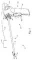
図1は、超音波外科用器具(50)、ゼネレータ(20)、及びゼネレータ(20)を外科用器具(50)に連結するように操作可能なケーブル(30)を含む例示的な超音波外科用システム(10)を示す。好適なゼネレータ(20)は、GEN 300(Cincinnati,OhioのEthicon Endo−Surgery,Inc.により販売)である。単なる例として、ゼネレータ(20)は、その開示が参照により本明細書に組み込まれる、2011年4月14日公開の「Surgical Generator for Ultrasonic and Electrosurgical Devices」と題する米国特許出願公開第2011/0087212号の教示に従って構成することができる。外科用器具(50)は超音波外科用器具を参照して記載されるが、以下に記載する技術は、本明細書の教示を考慮することで当業者には明かとなるであろうように、エンドカッター、把持具、カッター、ステープラー、クリップ適用器具、アクセス装置、薬物/遺伝子治療送達装置、及び超音波、RF、レーザー等を使用するエネルギー送達装置、並びに/又はこれらの任意の組み合わせを含むが、これらに限定されない多様な外科用器具と共に使用できることに留意するべきである。また、本実施例をケーブル接続の外科用器具(50)を参照して説明するが、外科用器具(50)は、その開示が参照により本明細書に組み込まれる、2009年6月4日公開の「Cordless Hand−held Ultrasonic Cautery Cutting Device」と題する米国特許出願公開第2009/0143797号に開示されているもの等のコードレストランス操作に適合されてもよいということが理解されるべきである。更に、外科用装置(50)は、また、2004年8月31日発行の「Robotic Surgical Tool with Ultrasound Cauterizing and Cutting Instrument」と題する米国特許第6,783,524号に開示されたようなロボット支援手術環境で使用されるか、又は使用に適合されてもよい。I. Overview of Exemplary Ultrasound Surgical System FIG. 1 illustrates an ultrasonic surgical instrument (50), a generator (20), and a cable (operable to connect the generator (20) to the surgical instrument (50). Fig. 3 shows an exemplary ultrasonic surgical system (10) including 30). A preferred generator (20) is GEN 300 (sold by Ethicon Endo-Surgery, Inc. of Cincinnati, Ohio). By way of example only, generator (20) is disclosed in US Patent Application Publication No. 2011/0087212, entitled “Surgical Generator for Ultrasonic and Electronic Devices,” published April 14, 2011, the disclosure of which is incorporated herein by reference. In accordance with the teachings of Although the surgical instrument (50) is described with reference to an ultrasonic surgical instrument, the techniques described below will be apparent to those skilled in the art in view of the teachings herein. , End cutters, grippers, cutters, staplers, clip appliers, access devices, drug / gene therapy delivery devices, and energy delivery devices using ultrasound, RF, laser, etc., and / or any combination thereof However, it should be noted that it can be used with a variety of surgical instruments that are not so limited. This example is also described with reference to a cabled surgical instrument (50), which is published June 4, 2009, the disclosure of which is incorporated herein by reference. It should be understood that it may be adapted to code restaurant operations such as those disclosed in US Patent Application Publication No. 2009/0143797, entitled “Cordless Hand-held Ultrasonic Catching Cutting Device”. In addition, the surgical device (50) is also robot-assisted as disclosed in US Pat. No. 6,783,524, entitled “Robotic Surgical Tool with Ultrasound Customizing and Cutting Instrument” issued August 31, 2004. It may be used in a surgical environment or adapted for use.
この例の外科用器具(50)は、組立形ハンドルアセンブリ(60)、長尺の伝達用アセンブリ(70)、及びトランスデューサ(100)を含む。伝達用アセンブリ(70)は、伝達用アセンブリ(70)の近位端で組立形ハンドルアセンブリ(60)に連結され、組立形ハンドルアセンブリ(60)から遠位方向に延びる。本実施例では、伝達用アセンブリ(70)は、内視鏡用途用の長尺の薄い管状アセンブリとして構成されているが、伝達用アセンブリ(70)は、代わりに、その開示が参照により本明細書に組み込まれる、2007年12月6日公開の「Ultrasonic Waveguide and Blade」と題する米国特許出願公開第2007/0282333号、及び「2008年8月21日公開のUltrasonic Device for Cutting and Coagulating」と題する米国特許出願公開第2008/0200940号に開示されているもの等の短いアセンブリであってもよいことが理解されるべきである。本実施例の伝達用アセンブリ(70)は、シース(72)、内管の作動部材(図示せず)、導波路(図示せず)、及び伝達用アセンブリ(70)の遠位端にあるエンドエフェクタ(80)を有する。本実施例において、エンドエフェクタ(80)は、導波路に連結されたブレード(82)、伝達用アセンブリ(70)の近位端で旋回するように操作可能であるクランプアーム(84)、及び所望により、クランプアーム(84)に連結し得る1つ又は2つ以上のクランプパッド(86)を備える。また、クランプアーム(84)及び関連する機能は、その開示が参照により本明細書に組み込まれる、1999年11月9日発行の「Ultrasonic Clamp Coagulator Apparatus Having Improved Clamp Arm Pivot Mount」と題する米国特許第5,980,510号の教示のうちの少なくとも一部により構成されかつ動作可能であることも理解されるべきである。導波路は、超音波エネルギーをトランスデューサ(100)からブレード(82)へ送信するように構成されているが、可撓性であるか、半可撓性であるか、又は剛性であってもよい。単に例示的な1つの超音波トランスデューサ(100)は、Cincinnati,OhioのEthicon Endo−Surgery,Inc.により販売されているModel No.HP054である。導波路は、また、当該技術分野において周知のように、導波路を経由してブレード(82)へ送信される機械的振動を増幅するように構成されてもよい。導波路は、導波路に沿った縦振動の利得を制御する機能、及び導波路を本装置の共振周波数に同調させる機能とを更に有してもよい。 The surgical instrument (50) of this example includes an assembled handle assembly (60), an elongated transmission assembly (70), and a transducer (100). The transmission assembly (70) is coupled to and extends distally from the assembled handle assembly (60) at the proximal end of the transmission assembly (70). In this example, the transmission assembly (70) is configured as an elongate thin tubular assembly for endoscopic applications, but the transmission assembly (70) is instead disclosed herein by reference. U.S. Patent Application Publication No. 2007/0282333 entitled “Ultrasonic Waveguide and Blade” published on Dec. 6, 2007 and “Ultrasonic Device for Cutting and Coagulation published on Aug. 21, 2008”, which are incorporated into this document. It should be understood that it may be a short assembly such as that disclosed in US Patent Application Publication No. 2008/0200940. The transmission assembly (70) of this embodiment includes a sheath (72), an inner tube actuating member (not shown), a waveguide (not shown), and an end at the distal end of the transmission assembly (70). It has an effector (80). In this example, the end effector (80) includes a blade (82) coupled to the waveguide, a clamp arm (84) operable to pivot at the proximal end of the transmission assembly (70), and a desired Provides one or more clamp pads (86) that can be coupled to the clamp arm (84). Also, the clamp arm (84) and related functions are described in U.S. Pat. No. 5,989,995 entitled "Ultrasonic Clamp Coagulator Approved Clamp Arm Pivot Mount", the disclosure of which is incorporated herein by reference. It should also be understood that it is constructed and operable in accordance with at least some of the teachings of 5,980,510. The waveguide is configured to transmit ultrasonic energy from the transducer (100) to the blade (82), but may be flexible, semi-flexible, or rigid. . One exemplary ultrasonic transducer (100) is an example of Ethicon Endo-Surgery, Inc. of Cincinnati, Ohio. Sold by Model No. HP054. The waveguide may also be configured to amplify mechanical vibrations transmitted through the waveguide to the blade (82), as is well known in the art. The waveguide may further have a function of controlling the gain of longitudinal vibration along the waveguide and a function of tuning the waveguide to the resonance frequency of the present device.
本実施例では、音響アセンブリが組織によって取り込まれないとき、音響アセンブリを好ましい共振周波数foに同調させるため、ブレード(82)の遠位端は波腹の近辺に配置される。トランスデューサ(100)にエネルギーが与えられるとき、ブレード(82)の遠位端は、例えば、55.5kHzの既定の振動周波数foで、最大振幅で例えば、約10〜500μmの範囲、好ましくは約20〜約200μmの範囲で長手方向に運動するように構成されている。本実施例のトランスデューサ(100)が駆動するとき、これらの機械的振動は、導波路を通ってエンドエフェクタ(80)へ送信される。本実施例において、ブレード(82)は、導波路に連結されているが、超音波振動数で振動する。したがって、ブレード(82)とクランプアーム(84)との間に組織が締め付けられたとき、ブレード(82)の超音波振動が、組織の切断と、隣接した組織細胞内のタンパク質の変性とを同時に行うことができ、それにより比較的小さい熱拡散で凝固効果が提供される。また、組織も焼灼するために、ブレード(82)とクランプアーム(84)を介して電流が提供されてもよい。伝達用アセンブリ(70)及びトランスデューサ(100)の幾つかの構成を記述してきたが、伝達用アセンブリ(70)及びトランスデューサ(100)の更に他の適切な構成は、本明細書の教示を考慮すれば当業者には明らかであると思われる。In this embodiment, when the acoustic assembly is not taken up by the tissue, for tuning the acoustic assembly to a preferred resonant frequency fo, the distal end of the blade (82) is disposed in the vicinity of the antinode. When energy is applied to the transducer (100), the distal end of the blade (82), for example, the default oscillation frequencyf o of 55.5 kHz, for example, the maximum amplitude in the range of about 10 to 500 [mu] m, preferably about It is configured to move in the longitudinal direction in the range of 20 to about 200 μm. When the transducer (100) of this example is driven, these mechanical vibrations are transmitted through the waveguide to the end effector (80). In this embodiment, the blade (82) is connected to the waveguide, but vibrates at the ultrasonic frequency. Therefore, when the tissue is clamped between the blade (82) and the clamp arm (84), the ultrasonic vibration of the blade (82) simultaneously cuts the tissue and denatures the protein in adjacent tissue cells. Can be performed, thereby providing a solidification effect with relatively little thermal diffusion. Current may also be provided through the blade (82) and the clamp arm (84) to cauterize the tissue. Although several configurations of the transmission assembly (70) and transducer (100) have been described, other suitable configurations of the transmission assembly (70) and transducer (100) may be considered in view of the teachings herein. Would be apparent to those skilled in the art.
この例の組立形ハンドルアセンブリ(60)は、結合ハウジング部分(62)及び下側部分(64)を有する。結合ハウジング部分(62)は、結合ハウジング部分(62)の近位端にトランスデューサ(100)を収容し、結合ハウジング部分(62)の遠位端に伝達用アセンブリ(70)の近位端を収容するように構成される。開口は、以下に更に詳細に記述されるが、様々な伝達用アセンブリ(70)を挿入するため、結合ハウジング部分(62)の遠位端に提供される。本実施例において、回転ノブ(66)は、伝達用アセンブリ(70)及び/又はトランスデューサ(100)を回転させるように図示されているが、回転ノブ(66)は単に所望によるものであるということが理解されるべきである。組立形ハンドルアセンブリ(60)の下側部分(64)は、トリガー(68)を具備し、かつ、使用者が片手で掴めるように構成されている。下側部分(64)のための単に例示的な1つの代替的な構成は、その開示が参照により本明細書に組み込まれる、2011年1月20日公開の「Rotating Transducer Mount for Ultrasonic Surgical Instruments」と題する米国特許出願公開第2011/0015660号の図1に示されている。トグルボタン(図示せず)は、下側部分(64)の遠位表面に位置してもよく、ゼネレータ(20)を用いて、様々な操作レベルでトランスデューサ(100)を作動するように操作可能である。例えば、第1のトグルボタンは、最大エネルギーレベルでトランスデューサ(100)を駆動することができるのに対し、第2のトグルボタンは、最小の非ゼロエネルギーレベルでトランスデューサ(100)を駆動することができる。当然ながら、トグルボタンは、本明細書の教示を考慮すれば当業者には明らかであると思われる、最大及び/又は最小エネルギーレベル以外のエネルギーレベルを得るように構成されてもよい。更に、トグルボタンは、組立形ハンドルアセンブリ(60)の上、トランスデューサ(100)の上、及び/又は外科用器具(50)から離れた場所のどこに配置されてもよく、また任意数のトグルボタンが、提供されてもよい。組立形ハンドルアセンブリ(60)を2つの別個の部分(62、64)に関して述べたが、組立形ハンドルアセンブリ(60)が、両方の部分(62、64)が組み合わされた単体アセンブリでもよいことが理解されるべきである。組立形ハンドルアセンブリ(60)は、あるいは、別個のトリガー部分(ユーザの手又は脚によって操作可能)や別個の結合ハウジング部分(62)などの複数の個別部品に分割されてもよい。トリガー部分は、トランスデューサ(100)を駆動することができ、また、連動するハウジング部分(62)から遠く離れていてもよい。本明細書の教示を考慮すれば当業者に明らかなように、組立形ハンドルアセンブリ(60)は、耐久性プラスチック(ポリカーボネートや液晶ポリマーなど)、セラミック及び/若しくは金属、又は任意の他の適切な材料から構成されてもよい。組立形ハンドルアセンブリ(60)に関する更なる他の構成は、本明細書の教示を考慮することで当業者には明かとなるであろう。例えば、器具(50)は、ロボットシステムの一部として操作されてもよい。また、本明細書の教示を考慮して、組立形ハンドルアセンブリ(60)の他の構成が当業者に明らかになる。単なる一例として、外科用器具(50)は、米国特許第5,980,510号、米国特許出願公開第2006/0079874号、同第2007/0191713号、同第2007/0282333号、同第2008/0200940号、同第2011/0015660号、米国特許第6,500,176号、同第2011/0087218号、及び/又は同第2009/0143797号の教示の少なくとも一部に従って構成することができる。 The assembled handle assembly (60) of this example has a coupling housing portion (62) and a lower portion (64). The coupling housing portion (62) houses the transducer (100) at the proximal end of the coupling housing portion (62) and the proximal end of the transmission assembly (70) at the distal end of the coupling housing portion (62). Configured to do. An opening, which will be described in more detail below, is provided at the distal end of the coupling housing portion (62) for insertion of various transmission assemblies (70). In this embodiment, the rotary knob (66) is shown as rotating the transmission assembly (70) and / or the transducer (100), but the rotary knob (66) is merely as desired. Should be understood. The lower portion (64) of the assembled handle assembly (60) includes a trigger (68) and is configured to be grasped by a user with one hand. One exemplary alternative configuration merely for the lower portion (64) is “Rotating Transducer Mount for Ultrasonic Surgical Instruments” published January 20, 2011, the disclosure of which is incorporated herein by reference. FIG. 1 of US Patent Application Publication No. 2011/0015660 entitled A toggle button (not shown) may be located on the distal surface of the lower portion (64) and can be manipulated using the generator (20) to actuate the transducer (100) at various operational levels. It is. For example, a first toggle button can drive the transducer (100) at a maximum energy level, while a second toggle button can drive the transducer (100) at a minimum non-zero energy level. it can. Of course, the toggle button may be configured to obtain energy levels other than the maximum and / or minimum energy levels that would be apparent to those skilled in the art in view of the teachings herein. Further, the toggle button may be located anywhere on the assembled handle assembly (60), on the transducer (100) and / or away from the surgical instrument (50), and any number of toggle buttons. May be provided. Although the assembled handle assembly (60) has been described with respect to two separate parts (62, 64), the assembled handle assembly (60) may be a unitary assembly in which both parts (62, 64) are combined. Should be understood. The assembled handle assembly (60) may alternatively be divided into a plurality of individual parts, such as a separate trigger portion (operable by the user's hand or leg) and a separate coupling housing portion (62). The trigger portion may drive the transducer (100) and may be remote from the interlocking housing portion (62). As will be apparent to those skilled in the art in view of the teachings herein, the assembled handle assembly (60) may be made of durable plastic (such as polycarbonate or liquid crystal polymer), ceramic and / or metal, or any other suitable You may be comprised from material. Still other configurations for the assembled handle assembly (60) will be apparent to those skilled in the art in view of the teachings herein. For example, the instrument (50) may be operated as part of a robotic system. Also, other configurations of the assembled handle assembly (60) will be apparent to those skilled in the art in view of the teachings herein. By way of example only, surgical instruments (50) are disclosed in US Pat. No. 5,980,510, US Patent Application Publication Nos. 2006/0079874, 2007/0191713, 2007/0282333, 2008 / May be configured in accordance with at least a portion of the teachings of US Patent No. 0200940, US 2011/0015660, US Patent Nos. 6,500,176, 2011/0087218, and / or 2009/0143797.
外科用器具(50)のための更なる任意の構成及び機構は、その開示が参照により本明細書に組み込まれる、本明細書と同日出願の「Ultrasonic Surgical Instrument with Modular End Effector」と題する米国特許出願第号[代理人整理番号END7012USNP.0587824]に記述されている。 A further optional configuration and mechanism for the surgical instrument (50) is a US patent entitled “Ultrasonic Surgical Instrument With Modular End Effector” filed on the same date as this specification, the disclosure of which is incorporated herein by reference. Application No. [Attorney Docket No. END7012USNP. [0587824].
II.例示的なラジオ周波数(RF)外科用器具の概要
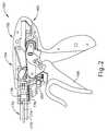
一部の外科用器具は、組織の手術のために超音波エネルギーを使用するようになされている一方で、図2〜3Bに示す外科用器具(150)などの他の外科用器具は、電気エネルギー及び/又は熱エネルギーなどのエネルギーを患者の組織に供給するように構成可能である。外科用器具(150)は、ハンドルアセンブリ(152)、伝達用アセンブリ(170)、及び伝達用アセンブリ(170)の遠位端に連結されたエンドエフェクタ(200)(図3A〜3Bに図示)を含む。下記により詳細に述べるように、ハンドルアセンブリ(152)は、エンドエフェクタ(200)に電気エネルギーを供給し、及び/又はエンドエフェクタ(200)内でナイフ又は切断部材(210)(図3A〜3Bに図示)を進めて、エンドエフェクタ(200)内で位置決めした組織を切り離すために1つ又は2つ以上のスイッチ及び/又はトリガーを含んでもよい。II. Overview of Exemplary Radio Frequency (RF) Surgical Instruments Some surgical instruments are adapted to use ultrasonic energy for tissue surgery, while the surgical instruments shown in FIGS. 2-3B Other surgical instruments, such as (150), can be configured to deliver energy, such as electrical energy and / or thermal energy, to the patient's tissue. The surgical instrument (150) includes a handle assembly (152), a transmission assembly (170), and an end effector (200) coupled to the distal end of the transmission assembly (170) (shown in FIGS. 3A-3B). Including. As described in more detail below, the handle assembly (152) provides electrical energy to the end effector (200) and / or a knife or cutting member (210) (see FIGS. 3A-3B) within the end effector (200). One or more switches and / or triggers may be included for advancing (shown) to disconnect tissue positioned within the end effector (200).
A.例示的なハンドルアセンブリ
図2を参照すると、ハンドルアセンブリ(152)は、ゼネレータ(20)などの電源(図示せず)及び/又は例えば、ハンドルアセンブリ(152)内に収容されている電源を含む、任意の他の電源と操作可能なように連結されている1つ又は2つ以上の電気的入力(160)を含む。伝達用アセンブリ(170)は、ハンドルアセンブリ(152)から遠位に延び、伝達用アセンブリ(170)の遠位端に連結したエンドエフェクタ(200)を含む。電源は、外科用器具(150)に電流を提供し、及び電源は、外科用器具(150)に所望の量のエネルギーを提供するために電流の大きさ、継続時間、波形、及び/又は周波数を制御するように操作可能であってもよい。本実施例のハンドルアセンブリ(152)は、インプット(160)に供給される電流がエンドエフェクタ(200)まで伝達可能なように、伝達用アセンブリ(170)から延びる第1の導体(220)により電気的入力(160)を電気的に連結するために、スイッチ又はトリガー(156)に対応するように構成されているハンドル本体(154)を含む。図2に示すように、ハンドル本体(154)は、一緒に組み立てられてハンドル本体(154)を形成する、2つの長手方向に二つ割りにした部分を含む。図2に示すように、一方の部分を省略して、ハンドルアセンブリ(152)の様々な内部の構成要素の一部を示す。様々な実施形態では、本明細書の教示を考慮すれば当業者には明らかであるように、ハンドル本体(154)の半体を、スナップ嵌め、プレス嵌め、溶接、接着、及び/又は相互締め付けを施すことができる。更になお、ハンドルアセンブリ(152)は、2つの別々の半体の代わりに一体化した片であってもよい。更に別の代替法では、この部分は半体でないが、単に取り外し可能な頂部及び/又は側面部分付きのハンドル本体(154)などの別々の連結可能な構成要素であってもよい。ハンドル本体(154)に対する更なる他の構成は、本明細書の教示を考慮することで当業者には明かとなるであろう。A. Exemplary Handle Assembly Referring to FIG. 2, the handle assembly (152) includes a power source (not shown) such as a generator (20) and / or a power source housed within the handle assembly (152), for example. One or more electrical inputs (160) are operably coupled to any other power source. The transmission assembly (170) includes an end effector (200) extending distally from the handle assembly (152) and coupled to the distal end of the transmission assembly (170). The power source provides current to the surgical instrument (150), and the power source provides current magnitude, duration, waveform, and / or frequency to provide the desired amount of energy to the surgical instrument (150). May be operable to control. The handle assembly (152) of this embodiment is electrically connected by a first conductor (220) extending from the transmission assembly (170) so that the current supplied to the input (160) can be transmitted to the end effector (200). A handle body (154) configured to correspond to a switch or trigger (156) is included to electrically couple the target input (160). As shown in FIG. 2, the handle body (154) includes two longitudinally divided portions that are assembled together to form the handle body (154). As shown in FIG. 2, one portion is omitted to show some of the various internal components of the handle assembly (152). In various embodiments, the half of the handle body (154) can be snap-fit, press-fit, welded, bonded, and / or interlocked, as will be apparent to those skilled in the art in view of the teachings herein. Can be applied. Still further, the handle assembly (152) may be an integral piece instead of two separate halves. In yet another alternative, this portion is not a half, but may simply be a separate connectable component such as a handle body (154) with removable top and / or side portions. Still other configurations for the handle body (154) will be apparent to those skilled in the art in view of the teachings herein.
第1の導体(220)は、エンドエフェクタ(200)内でトリガー(156)と第1の電極(230)との間(図3A〜3Bに図示)、及びトリガー(156)とインプット(160)との間にも延びる、絶縁ワイヤなどのワイヤを含む。本実施例では、第1の導体(220)は、上つかみ部(206)中の第1の電極(230)及び下つかみ部(208)内の第1の電極(230)へと連結されるが、第1の電極(230)が上つかみ部(206)のみ又は下つかみ部(208)内のみにあってもよいということが理解されるべきである。第1のスリップリング(176)は、伝達用アセンブリ(170)からハンドルアセンブリ(152)内に収容された第1の導体(220)の一部分まで延びた第1の導体(220)の一部分を電気的に連結する。ハンドルアセンブリ(152)は、インプット(160)により電源まで電気的に連結し、エンドエフェクタ(200)への伝達用アセンブリ(170)から第2の電極(232)まで延びる第2の導体(222)を更に含む。本実施例では、第2の導体(222)は、上つかみ部(206)中の第2の電極(232)及び下つかみ部(208)中の第2の電極(232)へと連結されるが、第2の電極(232)が上つかみ部(206)のみ又は下つかみ部(208)内のみにあってもよいということが理解されるべきである。伝達用アセンブリ(170)は、シャフト(174)に同軸であり、かつその周りに配設されて、シャフト(174)が外側シース(172)内に収容されている、外側シース(172)を含む。第2の導体(222)は、第1の導体(220)、シャフト(174)、及び/又は第1の電極(230)に対して第2の導体(222)を絶縁するために、絶縁性のプラスチックジャケット又はシース付きのワイヤを含む。第2のスリップリング(178)は、伝達用アセンブリ(170)からハンドルアセンブリ(152)内に収容されている第2の導体(222)の一部分まで延びる第2の導体(222)の一部分に電気的に連結するように構成されている。本実施例のスリップリング(176、178)は、ハンドル本体(154)に搭載され、伝達用アセンブリ(170)の一部分に搭載されている対応する円形又は少なくとも半円形の接点と接触を保つ、円形又は少なくとも半円形の接点を含む。このように、スリップリング(176、178)は、伝達用アセンブリ(170)から第1及び第2の導体(220、222)に対する電気的経路を依然として提供する一方で、ハンドルアセンブリ(152)に対する伝達用アセンブリ(170)の回転を可能にする。 The first conductor (220) is located in the end effector (200) between the trigger (156) and the first electrode (230) (shown in FIGS. 3A-3B), and the trigger (156) and the input (160). A wire such as an insulated wire that extends between the two. In this embodiment, the first conductor (220) is connected to the first electrode (230) in the upper grip portion (206) and the first electrode (230) in the lower grip portion (208). However, it should be understood that the first electrode (230) may be only in the upper grip (206) or only in the lower grip (208). The first slip ring (176) electrically connects a portion of the first conductor (220) that extends from the transmission assembly (170) to a portion of the first conductor (220) housed in the handle assembly (152). Are connected. The handle assembly (152) is electrically coupled to the power source by the input (160) and extends from the assembly (170) for transmission to the end effector (200) to the second electrode (232). Is further included. In this example, the second conductor (222) is connected to the second electrode (232) in the upper grip (206) and the second electrode (232) in the lower grip (208). However, it should be understood that the second electrode (232) may be only in the upper grip (206) or only in the lower grip (208). The transmission assembly (170) includes an outer sheath (172) that is coaxial with and disposed about the shaft (174) and the shaft (174) is received within the outer sheath (172). . The second conductor (222) is insulative to insulate the second conductor (222) from the first conductor (220), the shaft (174), and / or the first electrode (230). Wire with a plastic jacket or sheath. The second slip ring (178) is electrically connected to a portion of the second conductor (222) that extends from the transmission assembly (170) to a portion of the second conductor (222) housed within the handle assembly (152). It is comprised so that it may connect. The slip ring (176, 178) of the present example is mounted on the handle body (154) and is in circular contact with a corresponding circular or at least semi-circular contact mounted on a portion of the transmission assembly (170). Or at least a semi-circular contact. Thus, the slip rings (176, 178) still provide an electrical path from the transmission assembly (170) to the first and second conductors (220, 222) while transmitting to the handle assembly (152). Allows rotation of the assembly (170).
当然ながら、ハンドルアセンブリ(152)及び外科用器具(150)は他の構成を含んでもよい。例えば、ハンドルアセンブリ(152)及び/又は外科用器具(150)は、双極性のRFエネルギーを組織まで伝達する(例えば、組織の凝固又は封着する)、組織切断要素及び1つ又は2つ以上の要素を含んでもよい。このような器具の例は、Ethicon Endo−Surgery,Inc.(Cincinnati,Ohio)によるENSEAL(登録商標)組織封着器具である。このような器具及び関連する概念の更なる例は、その開示が参照により本明細書に組み込まれる、2002年12月31日発行の「Electrosurgical Systems and Techniques for Sealing Tissue」と題する米国特許第6,500,176号、その開示が参照により本明細書に組み込まれる、2006年9月26日発行の「Electrosurgical Instrument and Method of Use」と題する米国特許第7,112,201号、その開示が参照により本明細書に組み込まれる、2006年10月24日発行の「Electrosurgical Working End for Controlled Energy Delivery」と題する米国特許第7,125,409号、その開示が参照により本明細書に組み込まれる、2007年1月30日発行の「Electrosurgical Probe and Method of Use」と題する米国特許第7,169,146号、その開示が参照により本明細書に組み込まれる、2007年3月6日発行の「Electrosurgical Jaw Structure for Controlled Energy Delivery」と題する米国特許第7,186,253号、その開示が参照により本明細書に組み込まれる、2007年3月13日発行の「Electrosurgical Instrument」と題する米国特許第7,189,233号、その開示が参照により本明細書に組み込まれる、2007年5月22日発行の「Surgical Sealing Surfaces and Methods of Use」と題する米国特許第7,220,951号、その開示が参照により本明細書に組み込まれる、2007年12月8日発行の「Polymer Compositions Exhibiting a PTC Property and Methods of Fabrication」と題する米国特許第7,309,849号、その開示が参照により本明細書に組み込まれる、2007年12月25日発行の「Electrosurgical Instrument and Method of Use」と題する米国特許第7,311,709号、その開示が参照により本明細書に組み込まれる、2008年4月8日発行の「Electrosurgical Instrument and Method of Use」と題する米国特許第7,354,440号、その開示が参照により本明細書に組み込まれる、2008年6月3日発行の「Electrosurgical Instrument」と題する米国特許第7,381,209号、その開示が参照により本明細書に組み込まれる、2011年4月14日公開の「Surgical Instrument Comprising First and Second Drive Systems Actuatable by a Common Trigger Mechanism」と題する米国特許出願公開第2011/0087218号、その開示が参照により本明細書に組み込まれる、2011年6月2日出願の「Motor Driven Electrosurgical Device with Mechanical and Electrical Feedback」と題する米国特許出願第13/151,181号で開示されている。 Of course, the handle assembly (152) and the surgical instrument (150) may include other configurations. For example, the handle assembly (152) and / or the surgical instrument (150) transmits bipolar RF energy to the tissue (eg, coagulates or seals the tissue), the tissue cutting element and one or more It may contain the element. Examples of such instruments are described by Ethicon Endo-Surgery, Inc. (Cincinnati, Ohio) ENSEAL® tissue sealing device. A further example of such an instrument and related concepts is described in US Pat. No. 6, entitled “Electrological Systems and Techniques for Sealing Tissue” issued December 31, 2002, the disclosure of which is incorporated herein by reference. No. 500,176, US Pat. No. 7,112,201 entitled “Electronic Instrument and Method of Use” issued on Sep. 26, 2006, the disclosure of which is incorporated herein by reference. US entitled “Electrosurgical Working End for Control Energy Delivery” published October 24, 2006, incorporated herein. US Pat. No. 7,125,409, US Pat. No. 7,169,146, entitled “Electrological Probe and Method of Use,” issued January 30, 2007, the disclosure of which is incorporated herein by reference. U.S. Patent No. 7,186,253, entitled "Electrosurgical Jaw Structure for Controlled Energy Delivery", issued March 6, 2007, the disclosure of which is incorporated herein by reference. U.S. Patent No. 7,189,233 entitled "Electrosurgical Instrument" issued March 13, 2007, the disclosure of which is incorporated herein by reference, U.S. Patent No. 7,220,951 entitled "Surgical Sealing Surfaces and Methods of Use", issued on May 22, "Polymer Compositions Exhibiting" issued on December 8, 2007, the disclosure of which is incorporated herein by reference. U.S. Patent No. 7,309,849 entitled "a PTC Property and Methods of Fabrication", the disclosure of which is incorporated herein by reference, "Electrical Instrument and Method of Use" published December 25, 2007. US Pat. No. 7,311,709, published on Apr. 8, 2008, the disclosure of which is incorporated herein by reference. U.S. Patent No. 7,354,440 entitled "Electrosurgical Instrument and Method of Use", U.S. Patent No. 7, entitled "Electrosurgical Instrument", issued June 3, 2008, the disclosure of which is incorporated herein by reference. No. 381,209, the disclosure of which is incorporated herein by reference, “The Surgical Instrument Compiling First and Second Drive Actable by a Common Trigger US Patent Application No. 201 / published in the United States” published on Apr. 14, 2011. 0087218, the disclosure of which is incorporated herein by reference, 2011 No. 13 / 151,181 entitled “Motor Drive Electronic Device with Mechanical and Electrical Feedback” filed Jun. 2,
B.例示的なRFエンドエフェクタ
本実施例のエンドエフェクタ(200)は、上つかみ部(206)及び下つかみ部(208)を含む。上つかみ部(206)は、下つかみ部(208)に対して旋回可能であり、シャフト(174)の作動により組織を上つかみ部(206)と下つかみ部(208)との間で挟むように操作可能である。シャフト(174)の作動は、トリガー(156)を第2のトリガー、ボタン、モーター、ソレノイド、及び/又は任意の他の好適な方法により作動することにより行われてもよい。本実施例の上つかみ部(206)及び下つかみ部(208)の両方は、エンドエフェクタ(200)の近位端(202)と遠位端(204)との間に延びる第1の電極(230)を含む(図3A〜3Bに図示)。図4に示すように、本実施例の第1の電極(230)は、上つかみ部(206)及び下つかみ部(208)の両方の第1の側面に沿って延びる第1の側面部分、上つかみ部(206)及び下つかみ部(208)の両方の第2の側面に沿って延びる第2の側面部分、並びに上つかみ部(206)及び下つかみ部(208)の両方に対して第1の側面部分及び第2の側面部分を接続する横方向端部含む。本実施例の上つかみ部(206)及び下つかみ部(208)は、第1の電極(230)から絶縁され、かつ第1の電極(230)から挿入された類似の形状の第2の電極(232)を第1の電極(230)として更に含む。一部の変形では、第1の電極(230)は、代わりに上つかみ部(206)に対しては第2の電極(232)の挿入物であってよく、第2の電極(232)は、下つかみ部(208)に対しては第1の電極(230)の挿入物であってよく、その逆も成り立つ。他の変形では、上つかみ部(206)は第1の電極(230)のみを含み、下つかみ部(208)は第2の電極(232)のみを含み、その逆も成り立つ。更に別の構成では、第2の電極(232)は切断部材(210)により作動可能であってもよい。上つかみ部(206)及び下つかみ部(208)は両方とも、切断部材(210)の長手方向の並進が可能となるように構成された長手方向のチャンネル(図示せず)を含む。エンドエフェクタ(200)に対する更に他の構成は、その開示が参照により本明細書に組み込まれる、米国特許第6,500,176号、同第7,112,201号、同第7,125,409号、同第7,169,146号、同第7,186,253号、同第7,189,233号、同第7,220,951号、同第7,309,849号、同第7,311,709号、同第7,354,440号、同第7,381,209号、米国特許出願公開第2011/0087218号、及び/又は2011年6月2日出願の「Motor Driven Electrosurgical Device with Mechanical and Electrical Feedback」と題する米国特許出願第13/151,181号に開示されている。B. Exemplary RF End Effector The end effector (200) of this example includes an upper grip (206) and a lower grip (208). The upper gripping portion (206) is pivotable relative to the lower gripping portion (208), and the operation of the shaft (174) causes the tissue to be sandwiched between the upper gripping portion (206) and the lower gripping portion (208). Can be operated. Actuation of the shaft (174) may be performed by actuating the trigger (156) with a second trigger, button, motor, solenoid, and / or any other suitable method. Both the upper gripping portion (206) and the lower gripping portion (208) of the present embodiment have a first electrode (between the proximal end (202) and the distal end (204) of the end effector (200). 230) (shown in FIGS. 3A-3B). As shown in FIG. 4, the first electrode (230) of the present embodiment has a first side surface portion extending along the first side surfaces of both the upper grip portion (206) and the lower grip portion (208), A second side portion extending along the second side of both the upper grip portion (206) and the lower grip portion (208), and second relative to both the upper grip portion (206) and the lower grip portion (208). Including a lateral end connecting the one side portion and the second side portion. The upper grip part (206) and the lower grip part (208) of the present embodiment are insulated from the first electrode (230), and the second electrode having a similar shape inserted from the first electrode (230). (232) is further included as the first electrode (230). In some variations, the first electrode (230) may instead be an insert of the second electrode (232) relative to the upper grip (206), and the second electrode (232) The lower grip (208) may be an insert of the first electrode (230) and vice versa. In other variations, the upper grip (206) includes only the first electrode (230) and the lower grip (208) includes only the second electrode (232), and vice versa. In yet another configuration, the second electrode (232) may be actuable by a cutting member (210). Both the upper gripping portion (206) and the lower gripping portion (208) include a longitudinal channel (not shown) configured to allow longitudinal translation of the cutting member (210). Still other configurations for the end effector (200) are described in US Pat. Nos. 6,500,176, 7,112,201, 7,125,409, the disclosures of which are incorporated herein by reference. No. 7, 169, 146, No. 7, 186, 253, No. 7, 189, 233, No. 7, 220, 951, No. 7, 309, 849, No. 7 , 311,709, 7,354,440, 7,381,209, U.S. Patent Application Publication No. 2011/0087218, and / or “Motor Drive Electronic Device” filed on June 2, 2011. disclosed in US patent application Ser. No. 13 / 151,181 entitled “With Mechanical and Electrical Feedback”. That.
本実施例では、これは単に任意によることであるが、トリガー(156)(図2に示す)は、上つかみ部(206)と下つかみ部(208)との間で組織を挟み、かつ第1の導体(220)により電源から第1の電極(230)までエネルギーを選択的に供給するように操作可能である。一部の変形では、ボタンが電源から第1の電極(230)まで第1の導体(220)によりエネルギーを選択的に供給しながら、トリガー(156)は、組織を挟むように操作可能であってもよい。電源が電気入力(160)に連結されるとき、第2の電極(232)は第2の導体(222)により電源に定常的に連結状態にあってもよく、あるいは1つの代替的な例では、第2のトリガー及び/又はボタンは第2の電極(232)に電力を選択的に供給してもよい。したがって、トリガー(156)を作動させると、電流が第1の電極(230)から第2の電極(232)に流れて、その間の組織を焼灼する。この熱は組織内でコラーゲンを変性してもよく、エンドエフェクタ(200)のつかみ部(206、208)によりもたらされる挟み圧力と協動して、変性コラーゲンは組織内で封着を形成してもよい。他の変形では単極性RFエネルギー及び/又は加熱要素が使用されてもよいということが理解されるべきであるが、本実施例では、エンドエフェクタ(200)は、双極性RFエネルギーを使用して、組織を封着するように構成される。電流を流すようにするトリガー(156)の代わりに、電極(230、232)に電力を提供するために、別々のボタン(157)が使用されてもよい。例えば、ボタン(157)は、ゼネレータ(20)などの電源に信号を送って、電極(230、232)に電流を提供するが、単純にトリガー(156)を使用して、つかみ部(206、208)を機械的に一緒に挟んでもよい。加えて又は代わりに、ボタン(157)を同時に押すのでなければ、トリガー(156)が充分に作動不能であるように、ボタン(157)がトリガー(156)の機械的又は電気機械的なロックアウトをもたらしてもよい。加えて又はこのような機能の代わりに、トリガー(156)がボタン(157)にロックアウトをもたらしてもよい。 In this example, this is merely optional, but the trigger (156) (shown in FIG. 2) sandwiches the tissue between the upper grip (206) and the lower grip (208) and One conductor (220) is operable to selectively supply energy from the power source to the first electrode (230). In some variations, the trigger (156) is operable to sandwich tissue while the button selectively supplies energy from the power source to the first electrode (230) by the first conductor (220). May be. When the power source is coupled to the electrical input (160), the second electrode (232) may be steadily coupled to the power source by the second conductor (222), or in one alternative example The second trigger and / or button may selectively supply power to the second electrode (232). Thus, when the trigger (156) is activated, current flows from the first electrode (230) to the second electrode (232), cauterizing the tissue therebetween. This heat may denature the collagen within the tissue, and in cooperation with the pinching pressure provided by the gripping portions (206, 208) of the end effector (200), the denatured collagen forms a seal within the tissue. Also good. It should be understood that unipolar RF energy and / or heating elements may be used in other variations, but in this example, the end effector (200) uses bipolar RF energy. Configured to seal the tissue. Instead of a trigger (156) that causes current to flow, a separate button (157) may be used to provide power to the electrodes (230, 232). For example, the button (157) sends a signal to a power source such as a generator (20) to provide current to the electrodes (230, 232), but simply using the trigger (156), the grip (206, 208) may be sandwiched mechanically together. In addition or alternatively, the button (157) may be mechanically or electromechanically locked out of the trigger (156) so that the trigger (156) is not fully operational unless the buttons (157) are pressed simultaneously. May bring about. Additionally or alternatively, trigger (156) may provide a lockout to button (157).
本実施例では、電極(230、232)の第1の側面は、組織内で第1の封着を形成するように構成され、電極(230、232)の第2の側面は、組織内で第2の封着を形成するように構成される。当然ながら、他の構成は、任意の好適な数の封着を組織内で形成することができる複数の電極、及び/又は複数の電極部分を含んでもよい。組織は上つかみ部(206)及び下つかみ部(208)の長手方向のチャンネルの末端のいずれの側でも封着されるので、組織の2つの封着部分を切断するために、切断部材(210)は遠位に作動される。一部の変形では、切断部材(210)は、組織の封着に引き続いて作動されてもよい。加えて又は上述の代わりに、組織の切断を更に援助するために、RFエネルギーが切断部材(210)に供給されてもよい。実に、一部の変形では、切断部材(210)は鋭利でなくともよく、組織の切断は、鋭利でない切断部材(210)にRFエネルギーを供給し、切断部材(210)を遠位に進行させることにより行われる。更に、切断部材(210)は、第2のトリガー(図示せず)により、又は、1つの代替例では、トリガー(156)の更なる作動により作動されてもよい。本実施例では、切断部材(210)は、ブレードの相対する末端上に上フランジ及び下フランジを含み、それによりI形状の部材を形成する。切断部材(210)が遠位に作動されるにつれて、フランジは、上つかみ部(206)を下つかみ部(208)に対して圧縮するのを助ける。 In this example, the first side of the electrode (230, 232) is configured to form a first seal within the tissue, and the second side of the electrode (230, 232) is configured within the tissue. It is configured to form a second seal. Of course, other configurations may include multiple electrodes and / or multiple electrode portions that can form any suitable number of seals within the tissue. Since tissue is sealed on either side of the longitudinal channel ends of the upper grip (206) and lower grip (208), the cutting member (210) is used to cut the two sealed portions of tissue. ) Is actuated distally. In some variations, the cutting member (210) may be actuated subsequent to tissue sealing. Additionally or alternatively, RF energy may be supplied to the cutting member (210) to further assist in cutting the tissue. Indeed, in some variations, the cutting member (210) may not be sharp, and tissue cutting supplies RF energy to the non-sharp cutting member (210) and advances the cutting member (210) distally. Is done. Further, the cutting member (210) may be actuated by a second trigger (not shown) or, in one alternative, by further actuation of the trigger (156). In this example, the cutting member (210) includes an upper flange and a lower flange on opposite ends of the blade, thereby forming an I-shaped member. As the cutting member (210) is actuated distally, the flange helps compress the upper grip (206) against the lower grip (208).
当然ながら、エンドエフェクタ(200)及び外科用器具(150)は、更に、本明細書の教示を考慮すれば当業者には明らかであると思われるような他の構成を含んでもよい。 Of course, end effector (200) and surgical instrument (150) may further include other configurations as would be apparent to those skilled in the art in view of the teachings herein.
III.モジュール式シャフト及びエンドエフェクタのための例示的な連結機構
一部の事例では、同一のハンドルアセンブリ(60、152)を用いながら、様々なシャフトの長さ及び/又は様々な形のエンドエフェクタ(80、200)の間で変えることは有用であることがある。例えば、一部の処置において、大量の組織を切断する必要があり、様々な長さのエンドエフェクタ(80、200)、及び/又は伝達用アセンブリ(70、170)のためのシャフトを必要とすることがある。このような交換可能なシャフト及び/又はエンドエフェクタ(80、200)は、様々な外科的処置(例えば、開腹手術のための短いシャフト、低侵襲的腹腔鏡手術のための長いシャフト等)のために共通のハンドルアセンブリ(60、152)が用いられるのを可能にすることもある。更に、同一のハンドルアセンブリ(60、152)を再使用しながら、シャフト及び/又はエンドエフェクタ(80、200)を交換することは、様々な長さのシャフトの新たな外科用器具(50、150)を使用することに比べて、時間効率及び/又は費用効率がより高いこともある。単なる一例であるが、このようなシャフト及び/又はエンドエフェクタ(80、200)は、様々な長さ及び/又は種類を識別するためのカラーコードを備えることができる。別の事例では、ハンドルアセンブリ(60、152)は、様々な形のエンドエフェクタを用いるように構成され得、例えば、ハンドルアセンブリ(60、152)は、超音波エンドエフェクタ(80)及び/又はRFエンドエフェクタ(200)を操作するための構成要素を具備してもよい。このように、シャフト及び/又はエンドエフェクタ(80、200)を共通のハンドルアセンブリ(60、152)により交換することによって、時間及び/又はコストを節約することができる。したがって、モジュール式シャフトをハンドルアセンブリ(60、152)に連結するための様々な連結機構を以下に記述する。超音波エンドエフェクタ(80)が用いられる方法において、トランスデューサ(100)の少なくとも一部は、シャフト及びエンドエフェクタ(80)と一体になっていてもよく、したがって、ハンドルアセンブリ(60)と選択的に連結されていてもよいということが理解されるべきである。代わりに、トランスデューサ(100)は、シャフト及びエンドエフェクタ(80)がハンドルアセンブリ(60)と選択的に連結されるとき、シャフト及びエンドエフェクタ(80)がトランスデューサ(100)と選択的に連結されるように、ハンドルアセンブリ(60)と一体化していてもよい。III. Exemplary Coupling Mechanisms for Modular Shafts and End Effectors In some cases, using the same handle assembly (60, 152), different shaft lengths and / or different shapes of end effectors (80 , 200) may be useful. For example, in some procedures, a large amount of tissue needs to be cut, requiring various lengths of end effectors (80, 200) and / or shafts for transmission assemblies (70, 170). Sometimes. Such interchangeable shafts and / or end effectors (80, 200) may be used for various surgical procedures (eg, short shafts for open surgery, long shafts for minimally invasive laparoscopic surgery, etc.). May allow a common handle assembly (60, 152) to be used. Further, replacing the shaft and / or end effector (80, 200) while reusing the same handle assembly (60, 152) can result in new surgical instruments (50, 150) of various lengths of shaft. ) May be more time and / or cost effective. By way of example only, such shafts and / or end effectors (80, 200) may be provided with a color code to identify various lengths and / or types. In other cases, the handle assembly (60, 152) may be configured to use various forms of end effectors, for example, the handle assembly (60, 152) may include an ultrasonic end effector (80) and / or RF. Components for operating the end effector (200) may be provided. In this way, time and / or cost can be saved by replacing the shaft and / or end effector (80, 200) with a common handle assembly (60, 152). Accordingly, various coupling mechanisms for coupling the modular shaft to the handle assembly (60, 152) are described below. In the method in which the ultrasonic end effector (80) is used, at least a portion of the transducer (100) may be integral with the shaft and end effector (80) and thus selectively with the handle assembly (60). It should be understood that they may be linked. Instead, the transducer (100) is selectively coupled with the transducer (100) when the shaft and end effector (80) are selectively coupled with the handle assembly (60). As such, it may be integral with the handle assembly (60).
A.シャフト上の例示的な弾性タブ
第1の例示的な連結機構(300)は、例示的なエンドエフェクタアセンブリ(310)のシャフト(320)の挿入可能な部分から延びるタブ(302)を含む(図5A〜5Bに図示)。本実施例において、エンドエフェクタアセンブリ(310)は、伝達用アセンブリ(312)と、回転ノブ(314)と、回転ノブ(314)に対して近位に延びるシャフト(320)とを含む。回転ノブ(314)は、単に所望によるものであり、省略されてもよいということが理解されるべきである。他の変形では、回転ノブ(314)はハンドルアセンブリ(340)に連結されてもよく、エンドエフェクタアセンブリ(310)は回転ノブ(314)を通じて挿入されてもよい。回転ノブ(314)は、ハンドルアセンブリ(340)及び/又はシャフト(320)に対して伝達用アセンブリ(312)を回転させることができる。エンドエフェクタ(図示せず)は、伝達用アセンブリ(312)の遠位端に連結される。エンドエフェクタは、本明細書の教示を考慮すれば当業者には明らかであるように、超音波エンドエフェクタ(80)、RFエンドエフェクタ(200)、及び/又は任意の他のエンドエフェクタ又はエンドエフェクタの組み合わせを含んでもよい。エンドエフェクタ(80)などの超音波エンドエフェクタの事例では、シャフト(320)を通るシャフト穴(図示せず)は、伝達用アセンブリ(312)のシャフト(320)からのハンドルアセンブリ(340)内部の構成要素への機械的な連結を可能とし、上述の組立形ハンドルアセンブリ(60)に類似する方法で構成されてもよい。エンドエフェクタ(200)などのRFエンドエフェクタの場合、シャフト穴は、伝達用アセンブリ(312)の一部が、少なくとも部分的にシャフト(320)を通って延びるのを可能にする。伝達用アセンブリ(312)は、ハンドルアセンブリ(340)からエンドエフェクタへ電気的連結を行うことができるように、シャフト(320)内部の補足的なスリップリングコネクタに電気的に連結可能な内部スリップリングコネクタを具備してもよい。更にもう1つの代替例では、シャフト(320)を通り抜ける穴、及び/又は、エンドエフェクタアセンブリ(310)上の他の場所経由で流体連結を行うこともできる。A. Exemplary Elastic Tab on Shaft The first exemplary coupling mechanism (300) includes a tab (302) extending from an insertable portion of the shaft (320) of the exemplary end effector assembly (310) (FIG. 5A to 5B). In this example, the end effector assembly (310) includes a transmission assembly (312), a rotation knob (314), and a shaft (320) extending proximally with respect to the rotation knob (314). It should be understood that the rotary knob (314) is merely as desired and may be omitted. In other variations, the rotation knob (314) may be coupled to the handle assembly (340) and the end effector assembly (310) may be inserted through the rotation knob (314). The rotation knob (314) can rotate the transmission assembly (312) relative to the handle assembly (340) and / or the shaft (320). An end effector (not shown) is coupled to the distal end of the transmission assembly (312). The end effector may be ultrasonic end effector (80), RF end effector (200), and / or any other end effector or end effector, as will be apparent to those skilled in the art in view of the teachings herein. May be included. In the case of an ultrasonic end effector, such as the end effector (80), a shaft hole (not shown) through the shaft (320) is inside the handle assembly (340) from the shaft (320) of the transmission assembly (312). It can be mechanically connected to the component and may be configured in a manner similar to the assembled handle assembly (60) described above. In the case of an RF end effector, such as end effector (200), the shaft hole allows a portion of transmission assembly (312) to extend at least partially through shaft (320). The transmission assembly (312) is an internal slip ring that is electrically connectable to a complementary slip ring connector within the shaft (320) so that an electrical connection can be made from the handle assembly (340) to the end effector. A connector may be provided. In yet another alternative, fluid connections may be made through holes through the shaft (320) and / or elsewhere on the end effector assembly (310).
本実施例では、一対の弾性タブ(302)はシャフト(320)から外側に延びる。弾性タブ(302)は、プラスチックなどの弾性の非電導性材料を含んでもよく、又は弾性タブ(302)は金属材料などの電導性材料を含んでもよい。弾性タブ(302)が電導性であるならば、弾性タブ(302)は、また、エンドエフェクタの構成要素をハンドルアセンブリ(340)内の構成要素に電気的に連結するように操作可能である場合もある。例えば、弾性タブ(302)は、前述の第1及び第2の導体(220、222)の部分を電気的に連結してもよい。当然ながら、このような電気的連結は単に所望によるものである。図5A〜5Bに示すように、弾性タブ(302)は、シャフト(320)の近位端の近くのシャフト(320)に連結し、弾性タブ(302)が遠位に延びるにしたがって、シャフト(320)の長手方向の軸から外側に延びる。本実施例では、ハンドルアセンブリ(340)は、ケーシング(344)内部に形成され、かつ、エンドエフェクタアセンブリ(310)のシャフト(320)を受け入れるように構成されている、遠位開口部(342)を有するように示されている。ハンドルアセンブリ(340)は、その開示内容が参照により本明細書に組み込まれる、2011年1月20日公開の「Rotating Transducer Mount for Ultrasonic Surgical Instruments」と題する米国特許出願公開第2011/0015660号、又はその開示内容が参照により本明細書に組み込まれる、2002年12月31日発行の「Electrosurgical Systems and Techniques for Sealing Tissue」と題する米国特許第6,500,176号の組立形ハンドルアセンブリ(60)についての教示の少なくとも一部に従って、ハンドルアセンブリ(152)のために更に構成されてもよい。本実施例では、ロック解除スライダー(318)は、伝達用アセンブリ(312)の近位の部分上に配置され、タブ(302)に連結されている内部の作動可能部材(322)(仮想線で示す)に連結されている。ロック解除スライダー(318)は、シャフト(320)に向かって弾性タブ(302)を内側に引っ張るように、操作可能であり、それによって使用者がシャフト(320)をケーシング(344)から遠位に除去することが可能となる。あるいは、ロック解除スライダー(318)は回転ノブ(314)上に配置されてもよい。更になお、ハンドルアセンブリ(340)は、エンドエフェクタアセンブリ(310)をハンドルアセンブリ(340)から切り離すときに、弾性タブ(302)を押し下げる1つ又は2つ以上の抜去ボタン(図示せず)を含んでもよい。 In this embodiment, the pair of elastic tabs (302) extend outward from the shaft (320). The elastic tab (302) may include an elastic non-conductive material such as plastic, or the elastic tab (302) may include a conductive material such as a metallic material. If the elastic tab (302) is conductive, the elastic tab (302) is also operable to electrically connect the end effector component to the component in the handle assembly (340). There is also. For example, the elastic tab (302) may electrically connect portions of the first and second conductors (220, 222) described above. Of course, such electrical connection is merely as desired. As shown in FIGS. 5A-5B, the elastic tab (302) couples to the shaft (320) near the proximal end of the shaft (320) and as the elastic tab (302) extends distally, the shaft ( 320) extending outwardly from the longitudinal axis. In this example, the handle assembly (340) is formed within the casing (344) and is configured to receive the shaft (320) of the end effector assembly (310), the distal opening (342). It is shown to have US Patent Application Publication No. 2011/0015660 entitled “Rotating Transducer Mount for Ultrasonic Surgical Instruments” published Jan. 20, 2011, the disclosure of which is incorporated herein by reference, or handle assembly (340) US Pat. No. 6,500,176 assembled handle assembly (60) entitled “Electrosurgical Systems and Techniques for Sealing Tissue” issued December 31, 2002, the disclosure of which is incorporated herein by reference. May further be configured for the handle assembly (152) in accordance with at least some of the teachings herein. In this example, the unlocking slider (318) is disposed on the proximal portion of the transmission assembly (312) and is coupled to the tab (302) with an internal actuable member (322) (in phantom lines Connected). The unlocking slider (318) is operable to pull the elastic tab (302) inward toward the shaft (320), thereby allowing the user to move the shaft (320) distally from the casing (344). It can be removed. Alternatively, the unlocking slider (318) may be disposed on the rotary knob (314). Still further, the handle assembly (340) includes one or more eject buttons (not shown) that depress the elastic tab (302) when the end effector assembly (310) is disconnected from the handle assembly (340). But you can.
図5A〜5Bの順序に示すように、エンドエフェクタアセンブリ(310)のシャフト(320)を遠位開口部(342)の中に挿入するとき、弾性タブ(302)がシャフト(320)に対して押し下がり、エンドエフェクタアセンブリ(310)が挿入される。弾性タブ(302)の遠位端がケーシング(344)を遠位開口部(342)から越えたならば、弾性タブ(302)は元の向きに跳ね戻り、エンドエフェクタアセンブリ(310)をハンドルアセンブリ(340)に長手方向に連結する。一部の事例では、使用者は、スライダー(318)を作動させて、遠位開口部(342)の中への挿入時に弾性タブ(302)を手動で後退させてもよい。超音波器具の事例では、エンドエフェクタアセンブリ(310)のシャフト(320)は、上述のトランスデューサ(100)等のトランスデューサのホーンの上にねじ込まれてもよい。このようなねじ込みは、弾性タブ(302)の圧縮と同時に又は弾性タブ(302)がケーシング(344)を越えた後で行われてもよい。あるいは、RF器具の事例では、シャフト(320)は、1つ又は2つ以上の電気コネクタ(図示せず)と連結されて、エンドエフェクタを電源に連結することができる。図15〜17を参照して単に例示的な電気的連結を示し、説明する。図5Bに示すように、エンドエフェクタアセンブリ(310)は、ハンドルアセンブリ(340)に長手方向に効果的に固定され、ケーシング(314)に対するシャフト(320)、回転ノブ(314)、及び/又は伝達用アセンブリ(312)の回転運動を可能にする。使用者は、そのとき、組み立てられた外科用器具を処置のために使用してもよい。使用者がハンドルアセンブリ(340)からエンドエフェクタアセンブリ(310)を切り離したいときには、使用者は、弾性タブ(302)がシャフト(320)に充分に押し付けられて、使用者が遠位開口部(342)からケーシング(344)までシャフト(320)をスライドさせることができるまで、ロック解除スライダー(318)を遠位にスライドさせる。そのとき、使用者は、新たなエンドエフェクタアセンブリ(310)をハンドルアセンブリ(340)に連結することができる。 As shown in the sequence of FIGS. 5A-5B, when the shaft (320) of the end effector assembly (310) is inserted into the distal opening (342), the elastic tab (302) is against the shaft (320). Push down and the end effector assembly (310) is inserted. If the distal end of the elastic tab (302) passes over the casing (344) from the distal opening (342), the elastic tab (302) springs back and the end effector assembly (310) moves into the handle assembly. Connect to (340) in the longitudinal direction. In some cases, the user may actuate the slider (318) to manually retract the elastic tab (302) upon insertion into the distal opening (342). In the case of an ultrasonic instrument, the shaft (320) of the end effector assembly (310) may be screwed onto a transducer horn, such as the transducer (100) described above. Such screwing may occur simultaneously with compression of the elastic tab (302) or after the elastic tab (302) has passed over the casing (344). Alternatively, in the case of an RF instrument, the shaft (320) can be coupled with one or more electrical connectors (not shown) to couple the end effector to a power source. An exemplary electrical connection is only shown and described with reference to FIGS. As shown in FIG. 5B, the end effector assembly (310) is effectively secured longitudinally to the handle assembly (340) to provide a shaft (320), rotation knob (314), and / or transmission to the casing (314). Allows rotational movement of the assembly (312). The user may then use the assembled surgical instrument for the procedure. When the user wants to detach the end effector assembly (310) from the handle assembly (340), the user presses the elastic tab (302) fully against the shaft (320) and the user opens the distal opening (342). ) To slide the unlocking slider (318) distally until the shaft (320) can be slid from the casing (344). The user can then connect a new end effector assembly (310) to the handle assembly (340).
当然ながら、第1の連結機構(300)のための他の構成は、本明細書の教示を考慮すれば当業者には明らかであると思われる。例えば、弾性部材(302)は、タブ(302)をシャフト(320)から外側に押し出すために引っ張りバネを含んでもよい。更に、1つ又は2つ以上の弾性付勢されたカムは弾性タブ(302)を置き換えられてもよい。他の変形では、代わりに、弾性タブ(302)は、変形して、エンドエフェクタアセンブリ(310)の挿入を可能させるエラストマーくさびであってもよい。加えて、2つの弾性タブ(302)が図示されているが、単一の弾性タブ(302)又は2つ以上の弾性タブ(302)が第1の連結機構(300)と共に使用されてもよい。更には、エンドエフェクタアセンブリ(310)は、必ずしもハンドルアセンブリ(340)から取り外し可能である必要はない。このような事例では、使用者は、エンドエフェクタアセンブリ(310)及びハンドルアセンブリ(340)の両方を外科的処置の後に単に片付けるだけでよい。本明細書中の以後の開示から明らかであるように、様々な他の電気的及び/又は機械的連結機構及び/又は機能を第1の連結機構(300)と組み合わせてもよい。 Of course, other configurations for the first coupling mechanism (300) will be apparent to those skilled in the art in view of the teachings herein. For example, the elastic member (302) may include a tension spring to push the tab (302) outward from the shaft (320). Further, one or more elastically biased cams may replace the elastic tab (302). In other variations, the elastic tab (302) may instead be an elastomeric wedge that deforms to allow insertion of the end effector assembly (310). In addition, although two elastic tabs (302) are illustrated, a single elastic tab (302) or more than one elastic tab (302) may be used with the first coupling mechanism (300). . Further, the end effector assembly (310) need not necessarily be removable from the handle assembly (340). In such cases, the user may simply clear both the end effector assembly (310) and the handle assembly (340) after the surgical procedure. Various other electrical and / or mechanical coupling mechanisms and / or functions may be combined with the first coupling mechanism (300), as will be apparent from the subsequent disclosure herein.
B.例示的な可撓性ハンドルアセンブリ部分
第2の例示的な連結機構(400)は、代替的な例示的なエンドエフェクタアセンブリ(410)のシャフト(420)を捕捉するように構成された、ケーシング(444)の弾性付勢された部分(450)を含む(図6A〜6Bに図示)。本実施例において、エンドエフェクタアセンブリ(410)は、伝達用アセンブリ(412)と、回転ノブ(414)と、回転ノブ(414)に対して近位に延びるシャフト(420)とを含む。回転ノブ(414)は、単に所望によるものであり、省略されてもよいということが理解されるべきである。回転ノブ(414)は、ハンドルアセンブリ(440)及び/又はシャフト(420)に対して伝達用アセンブリ(412)を回転させることができる。エンドエフェクタ(図示せず)は、伝達用アセンブリ(412)の遠位端に連結される。エンドエフェクタは、本明細書の教示を考慮すれば当業者には明らかであるように、超音波エンドエフェクタ(80)、RFエンドエフェクタ(200)、及び/又は任意の他のエンドエフェクタ又はエンドエフェクタの組み合わせを含んでもよい。エンドエフェクタ(80)等の超音波エンドエフェクタの事例では、シャフト(420)を通るシャフト穴(図示せず)は、シャフト(420)を通る伝達用アセンブリ(412)が、上述の組立形ハンドルアセンブリ(60)に類似する方法で構成されることが可能な、ハンドルアセンブリ(440)内部の構成要素へ機械的に連結されるのを可能にする。エンドエフェクタ(200)などのRFエンドエフェクタの場合、シャフト穴は、伝達用アセンブリ(412)の一部が、少なくとも部分的にシャフト(420)を通って延びるのを可能にする。伝達用アセンブリ(412)は、ハンドルアセンブリ(440)からエンドエフェクタへ電気的連結を行うことができるように、シャフト(420)内部の補足的スリップリングコネクタに電気的に連結することのできる内部スリップリングコネクタを具備してもよい。更にもう1つの代替例では、シャフト(420)を通り抜ける穴、及び/又はエンドエフェクタアセンブリ(410)上の他の場所経由で流体連結を行うこともできる。B. Exemplary Flexible Handle Assembly Portion A second exemplary coupling mechanism (400) is a casing configured to capture the shaft (420) of an alternative exemplary end effector assembly (410). 444) of a resiliently biased portion (450) (shown in FIGS. 6A-6B). In this example, the end effector assembly (410) includes a transmission assembly (412), a rotation knob (414), and a shaft (420) extending proximally relative to the rotation knob (414). It should be understood that the rotary knob (414) is merely as desired and may be omitted. The rotation knob (414) can rotate the transmission assembly (412) relative to the handle assembly (440) and / or the shaft (420). An end effector (not shown) is coupled to the distal end of the transmission assembly (412). The end effector may be ultrasonic end effector (80), RF end effector (200), and / or any other end effector or end effector, as will be apparent to those skilled in the art in view of the teachings herein. May be included. In the case of an ultrasonic end effector, such as the end effector (80), a shaft hole (not shown) through the shaft (420) is connected to the transmission assembly (412) through the shaft (420) as described above for the assembled handle assembly. Allowing mechanical connection to components within the handle assembly (440), which can be configured in a manner similar to (60). In the case of an RF end effector, such as end effector (200), the shaft hole allows a portion of transmission assembly (412) to extend at least partially through shaft (420). The transmission assembly (412) is an internal slip that can be electrically connected to a complementary slip ring connector within the shaft (420) so that an electrical connection can be made from the handle assembly (440) to the end effector. A ring connector may be provided. In yet another alternative, fluid connections may be made via holes through the shaft (420) and / or elsewhere on the end effector assembly (410).
本実施例では、シャフト(420)は、回転ノブ(414)に近位であるが傾斜面(422)の遠位に位置する、周辺の傾斜面(422)及び周辺のくぼみ(424)を含む。本実施例では、ハンドルアセンブリ(440)は、ケーシング(444)内部に形成された遠位開口部(442)を有するように図示され、かつ、エンドエフェクタアセンブリ(410)のシャフト(420)を受け入れるように構成される。ハンドルアセンブリ(440)は、その開示内容が参照により本明細書に組み込まれる、2011年1月20日公開の「Rotating Transducer Mount for Ultrasonic Surgical Instruments」と題する米国特許出願公開第2011/0015660号、又は2002年12月31日発行の「Electrosurgical Systems and Techniques for Sealing Tissue」と題する米国特許第6,500,176号の組立形ハンドルアセンブリ(60)についての教示の少なくとも一部に従って、ハンドルアセンブリ(152)のために更に構成されてもよい。本実施例では、ハンドルアセンブリ(440)は、ハンドルアセンブリ(440)の遠位端に位置する1つ又は2つ以上の弾性付勢された部分(450)を含む。図6A〜6Bに示すように、1つ又は2つ以上のハンドル(452)は、弾性付勢された部分(450)に連結されて、シャフト(420)の挿入又はシャフト(420)の抜去時のいずれかにおいて使用者がハンドルアセンブリ(440)の遠位端を手動で開くことを可能とさせる。 In this example, the shaft (420) includes a peripheral inclined surface (422) and a peripheral indentation (424) that are proximal to the rotating knob (414) but distal to the inclined surface (422). . In this example, the handle assembly (440) is illustrated as having a distal opening (442) formed within the casing (444) and receives the shaft (420) of the end effector assembly (410). Configured as follows. US Patent Application Publication No. 2011/0015660 entitled “Rotating Transducer Mount for Ultrasonic Surgical Instruments” published January 20, 2011, the disclosure of which is incorporated herein by reference, or handle assembly (440) Handle assembly (152) according to at least part of the teachings on the assembled handle assembly (60) of US Pat. No. 6,500,176 entitled “Electrosurgical Systems and Techniques for Sealing Tissue”, issued December 31, 2002 It may be further configured for. In this example, the handle assembly (440) includes one or more resiliently biased portions (450) located at the distal end of the handle assembly (440). As shown in FIGS. 6A-6B, one or more handles (452) are coupled to the resiliently biased portion (450) for insertion of the shaft (420) or removal of the shaft (420). The user can manually open the distal end of the handle assembly (440).
図6A〜6Bの順序に示すように、エンドエフェクタアセンブリ(410)のシャフト(420)を遠位開口部(442)の中に挿入するとき、ハンドルアセンブリ(440)の弾性付勢された部分(450)は、シャフト(420)の周辺の傾斜面(422)の影響の下で外側にそる。弾性付勢された部分(450)の末端がくぼみ(424)に接すると、弾性付勢された部分(450)は元の向きに跳ね戻り、それによってエンドエフェクタアセンブリ(410)を回転ノブ(414)と周辺の傾斜面(422)の遠位壁との間でハンドルアセンブリ(440)に連結する。図6Bで示すように、エンドエフェクタアセンブリ(410)は、ケーシング(444)に対してシャフト(420)、回転ノブ(414)、及び/又は伝達用アセンブリ(412)の回転運動を可能にする一方で、ハンドルアセンブリ(440)に長手方向に効果的に固定される。超音波器具の事例では、エンドエフェクタアセンブリ(410)のシャフト(420)は、上述のトランスデューサ(100)等のトランスデューサのホーンの上に通されてもよい。このようなねじ込みは、弾性付勢された部分(450)の撓み変形と同時に又は弾性付勢された部分(450)がくぼみ(424)の中に跳ね戻った後で行われてもよい。あるいは、RF器具の事例では、シャフト(420)は、1つ又は2つ以上の電気コネクタ(図示せず)と連結されて、エンドエフェクタを電源に連結することができる。図15〜17を参照して単に例示的な電気的連結を図示し、説明する。使用者は、そのとき、組み立てられた外科用器具を処置のために用いることができる。使用者がハンドルアセンブリ(440)からエンドエフェクタアセンブリ(410)を切り離したいときには、使用者は、弾性付勢された部分(450)の末端が周辺の傾斜面(422)の遠位壁を越えるまで、弾性付勢された部分(450)の1つ又は2つ以上のハンドル(452)を外側に引っ張り、それによって使用者が周辺の傾斜面(422)及びシャフト(420)を弾性付勢された部分(450)から拡げられた遠位開口部(442)までスライドさせることが可能となる。そのとき、使用者は、新たなエンドエフェクタアセンブリ(410)をハンドルアセンブリ(440)に連結してもよい。一部の変形では、タブ(図示せず)が、弾性付勢された部分(450)を開くように旋回させるように設けられてもよい。したがって、使用者は、遠位開口部(442)を拡げるためにタブ上で押す必要があるだけである。 As shown in the sequence of FIGS. 6A-6B, when the shaft (420) of the end effector assembly (410) is inserted into the distal opening (442), an elastically biased portion of the handle assembly (440) ( 450) deflects outward under the influence of the inclined surface (422) around the shaft (420). When the end of the resiliently biased portion (450) contacts the indentation (424), the resiliently biased portion (450) bounces back, thereby causing the end effector assembly (410) to rotate with the rotary knob (414). ) And the distal wall of the peripheral ramp (422) to the handle assembly (440). As shown in FIG. 6B, the end effector assembly (410) allows rotational movement of the shaft (420), rotation knob (414), and / or transmission assembly (412) relative to the casing (444). And is effectively secured longitudinally to the handle assembly (440). In the case of an ultrasonic instrument, the shaft (420) of the end effector assembly (410) may be passed over a transducer horn, such as the transducer (100) described above. Such screwing may occur at the same time as the flexure deformation of the elastically biased portion (450) or after the elastically biased portion (450) has bounced back into the recess (424). Alternatively, in the case of an RF instrument, the shaft (420) can be coupled with one or more electrical connectors (not shown) to couple the end effector to a power source. An exemplary electrical connection is only shown and described with reference to FIGS. The user can then use the assembled surgical instrument for the procedure. When the user wants to detach the end effector assembly (410) from the handle assembly (440), the user will continue until the end of the resiliently biased portion (450) exceeds the distal wall of the peripheral ramp (422). One or more handles (452) of the elastically biased portion (450) are pulled outward, thereby causing the user to elastically bias the surrounding ramp (422) and shaft (420) It is possible to slide from the portion (450) to the extended distal opening (442). The user may then connect a new end effector assembly (410) to the handle assembly (440). In some variations, a tab (not shown) may be provided to pivot to open the resiliently biased portion (450). Thus, the user only needs to push on the tab to expand the distal opening (442).
当然ながら、第2の連結機構(400)のための他の構成は、本明細書の教示を考慮すれば当業者には明らかであると思われる。1つの代替的な構成では、弾性付勢された部分(450)はバネを省略してもよく、代わりに、ケーシング(444)の弾性的な撓み変形可能な部分であってもよい。あるいは、周辺の傾斜面(422)は、単一の連続した周辺の傾斜面の代わりにシャフト(420)の周りに配設された別々の傾斜面を含んでもよい。更になお、図5A〜5Bに示す弾性タブ(302)が周辺の傾斜面(422)の代わりに使用されてもよい。本明細書中の前出及び後出の開示から明白となるように、様々な他の電気的及び/又は機械的な連結機構及び/又は機能を第2の連結機構(400)とも組み合わせてもよい。 Of course, other configurations for the second coupling mechanism (400) will be apparent to those skilled in the art in view of the teachings herein. In one alternative configuration, the resiliently biased portion (450) may omit the spring, and may alternatively be an elastic, deflectable portion of the casing (444). Alternatively, the peripheral ramp (422) may include separate ramps disposed around the shaft (420) instead of a single continuous peripheral ramp. Still further, the elastic tab (302) shown in FIGS. 5A-5B may be used in place of the peripheral ramp (422). Various other electrical and / or mechanical coupling mechanisms and / or functions may also be combined with the second coupling mechanism (400), as will be apparent from the foregoing and following disclosure herein. Good.
C.例示的なスライドロック
第3の例示的な連結機構(500)は、更に別の例示的なエンドエフェクタアセンブリ(510)のシャフト(520)を捕捉するように構成されたケーシング(544)のスライドロック部分(550)を含む(図7A〜7Bに図示)。本実施例において、エンドエフェクタアセンブリ(510)は、伝達用アセンブリ(512)、回転ノブ(514)、及び回転ノブ(514)に対して近位に延びるシャフト(520)を含む。回転ノブ(514)は、単に所望によるものであり、省略されてもよいということが理解されるべきである。回転ノブ(514)は、伝達用アセンブリ(512)をハンドルアセンブリ(540)及び/又はシャフト(520)に対して回転させるように操作可能である。エンドエフェクタ(図示せず)は、伝達用アセンブリ(512)の遠位端に連結される。エンドエフェクタは、本明細書の教示を考慮すれば当業者には明らかであるように、超音波エンドエフェクタ(80)、RFエンドエフェクタ(200)及び又は他のいずれかのエンドエフェクタ又はエンドエフェクタの組み合わせを含んでもよい。エンドエフェクタ(80)などの超音波エンドエフェクタの事例では、シャフト(520)を通るシャフト穴(図示せず)は、伝達用アセンブリ(512)のシャフト(520)からのハンドルアセンブリ(540)内部の構成要素への機械的な連結を可能とし、上述の組立形ハンドルアセンブリ(60)に類似する方法で構成されてもよい。エンドエフェクタ(200)等のRFエンドエフェクタの場合、シャフト穴は、伝達用アセンブリ(512)の一部が、少なくとも部分的にシャフト(520)を通って延びるのを可能にする。伝達用アセンブリ(512)は、ハンドルアセンブリ(540)からエンドエフェクタへ電気的連結を行うことができるように、シャフト(520)内部の補足的スリップリングコネクタに電気的に連結可能な内部スリップリングコネクタを具備してもよい。更にもう1つの代替例では、シャフト(520)を通り抜ける穴、及び/又は、エンドエフェクタアセンブリ(510)上の他の場所経由で流体連結を行うこともできる。C. Exemplary Slide Lock The third exemplary coupling mechanism (500) is a slide lock of the casing (544) configured to capture the shaft (520) of yet another exemplary end effector assembly (510). Includes portion (550) (shown in FIGS. 7A-7B). In this example, the end effector assembly (510) includes a transmission assembly (512), a rotation knob (514), and a shaft (520) extending proximally relative to the rotation knob (514). It should be understood that the rotary knob (514) is merely desired and may be omitted. The rotation knob (514) is operable to rotate the transmission assembly (512) relative to the handle assembly (540) and / or the shaft (520). An end effector (not shown) is coupled to the distal end of the transmission assembly (512). The end effector may be an ultrasonic end effector (80), an RF end effector (200), and / or any other end effector or end effector, as will be apparent to those skilled in the art in view of the teachings herein. Combinations may be included. In the case of an ultrasonic end effector, such as the end effector (80), a shaft hole (not shown) through the shaft (520) is inside the handle assembly (540) from the shaft (520) of the transmission assembly (512). It can be mechanically connected to the component and may be configured in a manner similar to the assembled handle assembly (60) described above. For an RF end effector, such as end effector (200), the shaft hole allows a portion of the transmission assembly (512) to extend at least partially through the shaft (520). The transmission assembly (512) is an internal slip ring connector that is electrically connectable to a complementary slip ring connector within the shaft (520) so that an electrical connection can be made from the handle assembly (540) to the end effector. You may comprise. In yet another alternative, the fluid connection may be made via a hole through the shaft (520) and / or elsewhere on the end effector assembly (510).
本実施例では、シャフト(520)は、環状フランジ(522)の遠位で、回転ノブ(514)の近位に位置するくぼみ(524)付きの環状フランジ(522)を含む。スライドロック部分(550)は、スライドロック部分(550)をロックされた位置にスライド可能なように並進させるとき、エンドエフェクタアセンブリ(510)のシャフト(520)を固定するように構成されたノッチ(552)(仮想線で示す)を含む。ノッチ(552)は、図11Aに示すノッチ(952)に類似して構成されてもよい。ハンドルアセンブリ(540)は、その開示内容が参照により本明細書に組み込まれる、2011年1月20日公開の「Rotating Transducer Mount for Ultrasonic Surgical Instruments」と題する米国特許出願公開第2011/0015660号、又は2002年12月31日発行の「Electrosurgical Systems and Techniques for Sealing Tissue」と題する米国特許第6,500,176号の組立形ハンドルアセンブリ(60)についての教示の少なくとも一部に従って、ハンドルアセンブリ(152)のために更に構成されてもよい。本実施例では、スライドロック部分(550)は、ハンドルアセンブリ(540)の遠位端に位置し、図7Aに示す開放位置(その中にシャフト(520)及び環状フランジ(522)を挿入してもよい開口がケーシング(544)中に形成されている)と図7Bに示すロックされた位置との間をスライド可能なように並進するように構成される。本実施例のスライドロック部分(550)は、手動で並進可能な部分であるが、ロックされた位置にスライドロック部分(550)を戻すように付勢された戻りバネを含んでもよいということが理解されるべきである。本実施例では、スライドロック部分(550)は、ケーシング(544)中に形成された垂直なチャンネル(図示せず)内に収容され、タブ(図示せず)を含み、それによってスライドロック部分(550)の運動をチャンネル内の垂直な並進に限定する。スライドロック部分(550)は、スライドロック部分がロックされた位置にあるとき、ケーシング(544)の上部分にスライドロック部分(550)を連結するように操作可能なスナップ嵌めを更に含んでもよい。 In this example, the shaft (520) includes an annular flange (522) with a recess (524) located distal to the annular flange (522) and proximal to the rotation knob (514). The slide lock portion (550) is a notch configured to secure the shaft (520) of the end effector assembly (510) when the slide lock portion (550) is slidably translated to the locked position. 552) (indicated by phantom lines). Notch (552) may be configured similar to notch (952) shown in FIG. 11A. US Patent Application Publication No. 2011/0015660 entitled “Rotating Transducer Mount for Ultrasonic Surgical Instruments” published January 20, 2011, the disclosure of which is incorporated herein by reference, or handle assembly (540) In accordance with at least part of the teachings on the assembled handle assembly (60) of US Pat. No. 6,500,176 entitled “Electrosurgical Systems and Techniques for Sealing Tissue”, issued December 31, 2002 It may be further configured for. In this example, the slide lock portion (550) is located at the distal end of the handle assembly (540), with the open position shown in FIG. 7A (with the shaft (520) and annular flange (522) inserted therein. A good opening is formed in the casing (544)) and is configured to translate slidably between the locked position shown in FIG. 7B. The slide lock portion (550) of the present embodiment is a manually translatable portion, but may include a return spring biased to return the slide lock portion (550) to the locked position. Should be understood. In this embodiment, the slide lock portion (550) is housed in a vertical channel (not shown) formed in the casing (544) and includes a tab (not shown), whereby the slide lock portion ( 550) is limited to vertical translation within the channel. The slide lock portion (550) may further include a snap fit operable to couple the slide lock portion (550) to the upper portion of the casing (544) when the slide lock portion is in the locked position.
図7A〜7Bの順序に示すように、スライドロック部分(550)は、シャフト(520)及び環状フランジ(522)がハンドルアセンブリ(540)の中に挿入され得る、開口を形成するために、スライド可能なように並進される。超音波器具の事例では、エンドエフェクタアセンブリ(510)のシャフト(520)は、上述のトランスデューサ(100)等のトランスデューサのホーンの上に通されてもよい。このようなねじ込みは、スライドロック部分(550)をロックされた位置の中にスライドさせる前、同時、又は後で行われてもよい。あるいは、RF器具の事例では、シャフト(520)は、1つ又は2つ以上の電気コネクタ(図示せず)と連結されて、エンドエフェクタを電源に連結することができる。図15〜17を参照して単に例示的な電気的連結を図示し、説明する。手動で操作可能なスライドロック部分(550)を使用するならば、使用者は、ノッチ(552)がシャフト(520)のくぼみ(524)と位置合わせするように、スライドロック部分(550)を上方にスライド可能なように並進させる。図7Bに示すように、エンドエフェクタアセンブリ(510)は、スライドロック部分(550)、環状フランジ(522)、及び回転ノブ(514)を組み合わせることにより、ケーシング(544)に対してシャフト(520)、回転ノブ(514)、及び/又は伝達用アセンブリ(512)の回転運動をなお可能とさせる一方で、ハンドルアセンブリ(540)に長手方向に効率的に固定される。使用者は、そのとき、組み立てられた外科用器具を処置のために用いることができる。使用者がハンドルアセンブリ(540)からエンドエフェクタアセンブリ(510)を切り離したいときには、使用者は、環状フランジ(522)及びシャフト(520)がスライドロック部分(550)及び/又はノッチ(552)を越えることができるまで、スライドロック部分(550)を下方にスライド可能なように並進させる。そのとき、使用者は、新たなエンドエフェクタアセンブリ(510)をハンドルアセンブリ(540)に連結することができる。 As shown in the sequence of FIGS. 7A-7B, the slide lock portion (550) slides to form an opening through which the shaft (520) and annular flange (522) can be inserted into the handle assembly (540). Translated as possible. In the case of an ultrasonic instrument, the shaft (520) of the end effector assembly (510) may be passed over a transducer horn, such as the transducer (100) described above. Such screwing may occur before, simultaneously with, or after sliding the slide lock portion (550) into the locked position. Alternatively, in the case of an RF instrument, the shaft (520) can be coupled to one or more electrical connectors (not shown) to couple the end effector to a power source. An exemplary electrical connection is only shown and described with reference to FIGS. If a manually operable slide lock portion (550) is used, the user can move the slide lock portion (550) upward so that the notch (552) is aligned with the recess (524) of the shaft (520). Translate so that it can slide. As shown in FIG. 7B, the end effector assembly (510) has a shaft (520) relative to the casing (544) by combining a slide lock portion (550), an annular flange (522), and a rotation knob (514). , Rotation knob (514), and / or transmission assembly (512), while still allowing rotational movement, while being efficiently secured longitudinally to handle assembly (540). The user can then use the assembled surgical instrument for the procedure. When the user wishes to disconnect the end effector assembly (510) from the handle assembly (540), the user may have the annular flange (522) and shaft (520) over the slide lock portion (550) and / or notch (552). The slide lock portion (550) is translated so that it can slide downward until it can. The user can then connect a new end effector assembly (510) to the handle assembly (540).
当然ながら、第3の連結機構(500)のための他の構成は、本明細書の教示を考慮すれば当業者には明らかであると思われる。本明細書中の前出及び後出の開示から明白と7なるように、様々な他の電気的な及び/又は機械的な連結機構及び/又は機能を第3の連結機構(500)と組み合わせてもよい。 Of course, other configurations for the third coupling mechanism (500) will be apparent to those skilled in the art in view of the teachings herein. Various other electrical and / or mechanical coupling mechanisms and / or functions may be combined with the third coupling mechanism (500), as will become apparent from the disclosure above and later herein. May be.
D.例示的なネジ付きスリップナット
第4の例示的な連結機構(600)は、例示的なエンドエフェクタアセンブリ(610)のシャフト(620)の周りに配置されるネジ付きスリップナット(630)を含む(図8A〜8Bに図示)。本実施例において、エンドエフェクタアセンブリ(610)は、伝達用アセンブリ(612)、回転ノブ(614)、及び回転ノブ(614)に対して近位に延びるシャフト(620)を含む。回転ノブ(614)は、単に所望によるものであり、省略されてもよいということが理解されるべきである。回転ノブ(614)は、ハンドルアセンブリ(640)及び/又はシャフト(620)に対して伝達用アセンブリ(612)を回転させることができる。エンドエフェクタ(図示せず)は、伝達用アセンブリ(612)の遠位端に連結される。エンドエフェクタは、超音波エンドエフェクタ(80)、RFエンドエフェクタ(200)及び/又は本明細書の教示を考慮すれば当業者には明らかであると思われるような他のいずれかのエンドエフェクタ又は複数のエンドエフェクタの組み合わせを含んでもよい。エンドエフェクタ(80)などの超音波エンドエフェクタの事例では、シャフト(620)を通るシャフト穴(図示せず)は、伝達用アセンブリ(612)のシャフト(620)からのハンドルアセンブリ(640)内部の構成要素への機械的な連結を可能とし、上述の組立形ハンドルアセンブリ(60)に類似する方法で構成されてもよい。エンドエフェクタ(200)等のRFエンドエフェクタの場合、シャフト穴は、伝達用アセンブリ(612)の一部が、少なくとも部分的にシャフト(620)を通って延びるのを可能にする。伝達用アセンブリ(612)は、ハンドルアセンブリ(640)からエンドエフェクタへ電気的連結を行うことができるような具合に、シャフト(620)内部の補足的スリップリングコネクタに電気的に連結することのできる内部スリップリングコネクタを具備することができる。更にもう1つの代替例では、シャフト(620)を通り抜ける穴によって、及び/又は、エンドエフェクタアセンブリ(610)上の他の場所に流体連結を行うこともできる。D. Exemplary Threaded Slip Nut A fourth exemplary coupling mechanism (600) includes a threaded slip nut (630) disposed about the shaft (620) of the exemplary end effector assembly (610) ( 8A-8B). In this example, the end effector assembly (610) includes a transmission assembly (612), a rotation knob (614), and a shaft (620) extending proximally relative to the rotation knob (614). It should be understood that the rotary knob (614) is merely optional and may be omitted. The rotation knob (614) can rotate the transmission assembly (612) relative to the handle assembly (640) and / or the shaft (620). An end effector (not shown) is coupled to the distal end of the transmission assembly (612). The end effector may be an ultrasonic end effector (80), an RF end effector (200) and / or any other end effector as would be apparent to one of ordinary skill in the art in view of the teachings herein. A combination of a plurality of end effectors may be included. In the case of an ultrasonic end effector, such as the end effector (80), a shaft hole (not shown) through the shaft (620) is inside the handle assembly (640) from the shaft (620) of the transmission assembly (612). It can be mechanically connected to the component and may be configured in a manner similar to the assembled handle assembly (60) described above. For an RF end effector, such as end effector (200), the shaft hole allows a portion of the transmission assembly (612) to extend at least partially through the shaft (620). The transmission assembly (612) can be electrically coupled to a complementary slip ring connector within the shaft (620) such that an electrical connection can be made from the handle assembly (640) to the end effector. An internal slip ring connector can be provided. In yet another alternative, fluid connections may be made by holes through the shaft (620) and / or elsewhere on the end effector assembly (610).
本実施例では、ネジ付きスリップナット(630)は、シャフト(620)の周りに摺動可能なように配置される。ネジ付きスリップナット(630)は、ネジ付きスリップナット(630)の近位端に(仮想線で示す)キー溝(632)を具備する。キー溝(632)は、あるいは、ネジ付きスリップナット(630)の遠位端に位置決めされることが可能であるということが理解されるべきである。あるいは、キー溝(632)は、ネジ付きスリップナット(630)から充分に延びてもよいが、本実施例のキー溝(632)は、ネジ付きスリップナット(630)から部分的に延びるのみである。図8A〜8Bに示すように、キー溝(632)は、シャフト(620)のキー付き部分(622)を受け入れるように構成される。本実施例では、シャフト(620)のキー付き部分(622)は、シャフト(620)の近位端の近辺に位置し、かつ、シャフト(620)から外に向かって延びるが、キー付き部分(622)は、回転ノブ(614)の近辺又はシャフト(620)の中点で遠位に位置してもよいということが理解されるべきである。1つの単なる代替例では、キー付き部分(622)は、スライドキー付き部分(622)をキー溝(632)の中にスライドするために、例えば、図5A〜5Bに示すスライダー(318)の作動によりシャフト(620)に対してスライド可能であってもよい。シャフト(620)は、シャフト(620)の近位端に位置し、かつ、ネジ付きスリップナット(630)がシャフト(620)の近位に滑り落ちるのを防ぐような大きさにされている、近位フランジ(624)を更に含む。以下に述べられるように、使用者が、ハンドルアセンブリ(640)の雌ネジ(650)の中にネジ付きスリップナット(630)を通すことを望むとき、キー付き部分(622)はキー溝(632)の中に挿入可能である。本実施例のネジ付きスリップナット(630)は、次いで、キー付き部分(622)をキー溝(632)から引き離すためにシャフト(620)上で遠位にスリップさせられ、それによって、シャフト(620)、回転ノブ(614)、及び/又は伝達用アセンブリ(612)が、ネジ付きスリップナット(630)及び/又はハンドルアセンブリ(640)に対して自由に回転することが可能になる。 In this embodiment, the threaded slip nut (630) is slidably disposed about the shaft (620). The threaded slip nut (630) includes a keyway (632) (shown in phantom) at the proximal end of the threaded slip nut (630). It should be understood that the keyway (632) can alternatively be positioned at the distal end of the threaded slip nut (630). Alternatively, the keyway (632) may extend sufficiently from the threaded slip nut (630), but the keyway (632) of this example only extends partially from the threaded slip nut (630). is there. As shown in FIGS. 8A-8B, the keyway (632) is configured to receive a keyed portion (622) of the shaft (620). In this example, the keyed portion (622) of the shaft (620) is located near the proximal end of the shaft (620) and extends outwardly from the shaft (620), but the keyed portion ( It should be understood that 622) may be located near the rotation knob (614) or distally at the midpoint of the shaft (620). In one mere alternative, the keyed portion (622) is actuated by, for example, the slider (318) shown in FIGS. May be slidable relative to the shaft (620). The shaft (620) is located at the proximal end of the shaft (620) and is sized to prevent the threaded slip nut (630) from sliding down proximal of the shaft (620). It further includes a positioning flange (624). As described below, when the user wishes to pass the threaded slip nut (630) through the female thread (650) of the handle assembly (640), the keyed portion (622) is key groove (632). ) Can be inserted. The threaded slip nut (630) of this example is then slipped distally on the shaft (620) to pull the keyed portion (622) away from the keyway (632), thereby causing the shaft (620) ), The rotation knob (614), and / or the transmission assembly (612) are free to rotate relative to the threaded slip nut (630) and / or the handle assembly (640).
一部の事例では、ネジ付きスリップナット(630)は、例えば、上述の内管の作動部材等の内管の上にスリップ可能なように配置されてもよい。このような構成では、ネジ付きスリップナット(630)は、その開示が参照により本明細書に組み込まれる、2011年1月20日公開の「Rotating Transducer Mount for Ultrasonic Surgical Instruments」と題する米国特許出願公開第2011/0015660号で記述されている、トリガーヨーク(185)などのヨークの中に通るように構成されてもよい。上述のブレード(82)などのブレードは、上述のトランスデューサ(100)などのトランスデューサに連結されるように構成されてもよい。内管作動部材は、ネジ付きスリップナット(630)をヨークに連結することによって作動されてもよい。したがって、上述のクランプアーム(84)などのクランプアームは、ブレードに組織を挟むように作動可能である。 In some cases, the threaded slip nut (630) may be slidably disposed over an inner tube, such as, for example, the inner tube actuation member described above. In such a configuration, a threaded slip nut (630) is disclosed in US patent application entitled “Rotating Transducer Mount for Ultrasonic Surgical Instruments” published on Jan. 20, 2011, the disclosure of which is incorporated herein by reference. It may be configured to pass through a yoke such as the trigger yoke (185) described in 2011/0015660. A blade, such as the blade (82) described above, may be configured to be coupled to a transducer, such as the transducer (100) described above. The inner tube actuating member may be actuated by connecting a threaded slip nut (630) to the yoke. Thus, a clamp arm, such as the clamp arm (84) described above, is operable to sandwich tissue between the blades.
本実施例では、ハンドルアセンブリ(640)は、ケーシング(644)内部に形成された遠位開口部(642)を有するように図示され、かつ、シャフト(620)及びエンドエフェクタアセンブリ(610)のネジ付きスリップナット(630)を受け入れるように構成される。ハンドルアセンブリ(640)は、その開示内容が参照により本明細書に組み込まれる、2011年1月20日公開の「Rotating Transducer Mount for Ultrasonic Surgical Instruments」と題する米国特許出願公開第2011/0015660号、又は2002年12月31日発行の「Electrosurgical Systems and Techniques for Sealing Tissue」と題する米国特許第6,500,176号の組立形ハンドルアセンブリ(60)についての教示の少なくとも一部に従って、ハンドルアセンブリ(152)のために更に構成されてもよい。本実施例では、ハンドルアセンブリ(640)は、部材開口(652)の周りに配置された雌ネジ(650)を有する部材(648)を具備する。雌ネジ(650)及びネジ付きスリップナット(630)は、エンドエフェクタアセンブリ(610)をハンドルアセンブリ(640)に固定するために、一緒にねじ込むように構成される。 In this example, the handle assembly (640) is illustrated as having a distal opening (642) formed within the casing (644) and the screw of the shaft (620) and end effector assembly (610). Configured to receive a slip nut (630). US Patent Application Publication No. 2011/0015660 entitled “Rotating Transducer Mount for Ultrasonic Surgical Instruments” published January 20, 2011, the disclosure of which is incorporated herein by reference, or handle assembly (640) Handle assembly (152) according to at least part of the teachings on the assembled handle assembly (60) of US Pat. No. 6,500,176 entitled “Electrosurgical Systems and Techniques for Sealing Tissue”, issued December 31, 2002 It may be further configured for. In this example, the handle assembly (640) includes a member (648) having an internal thread (650) disposed about the member opening (652). The internal thread (650) and the threaded slip nut (630) are configured to screw together to secure the end effector assembly (610) to the handle assembly (640).
図8A〜8Bの順序に示すように、本実施例のネジ付きスリップナット(630)は、シャフト(620)のキー付き部分(622)がネジ付きスリップナット(630)のキー溝(632)に嵌合するように、近位でスライドされる。ネジ付きスリップナット(630)の回転の自由度が、キー付き部分(622)とキー溝(632)との係合によって制限され、使用者は、ネジ付きスリップナット(630)をハンドルアセンブリ(640)の雌ネジ(650)の中にねじ込む。例えば、使用者は、ネジ付きスリップナット(630)を雌ネジ(650)の中にねじ込むのと同時に、ネジ付きスリップナット(630)をシャフト(620)上でフランジ(624)に対して近位に動かすように、L形スペーサツールが使用されてもよい。あるいは、使用者は、ネジ付きスリップナット(630)を手動で近位に付勢してもよい。更にまた、上述のようなスライダーは、ネジ付きスリップナット(630)の一部分と係合して、ネジ付きスリップナット(630)を近位に動かしてもよい。当然ながら、ネジ付きスリップナット(630)を近位に動かして、キー付き部分(622)とキー溝(632)とを係合する更に他の方法は、本明細書の教示を考慮すれば当業者には明らかであると思われる。例えば、バネ(図示せず)は、スリップナット(630)の遠位で回転ノブ(614)の近位のシャフト(620)の周りに配置され、それによって、キー溝(632)がキー付き部分(622)と係合するように、スリップナット(630)を近位に付勢させてもよい。使用者が、エンドエフェクタアセンブリ(610)を回転させることを望むとき、使用者は、回転ノブ(614)を掴んで、キー付き部分(622)がキー溝(632)から引き離されるまで、エンドエフェクタアセンブリ(610)を近位に押す。 As shown in the order of FIGS. 8A to 8B, the threaded slip nut (630) of the present embodiment has a keyed portion (622) of the shaft (620) in the key groove (632) of the threaded slip nut (630). Slide proximally to mate. The degree of freedom of rotation of the threaded slip nut (630) is limited by the engagement of the keyed portion (622) and the keyway (632), and the user attaches the threaded slip nut (630) to the handle assembly (640). ) Into the female screw (650). For example, the user may screw the threaded slip nut (630) into the female thread (650) and at the same time place the threaded slip nut (630) proximal to the flange (624) on the shaft (620). An L-shaped spacer tool may be used to move it. Alternatively, the user may manually bias the threaded slip nut (630) proximally. Furthermore, the slider as described above may engage a portion of the threaded slip nut (630) to move the threaded slip nut (630) proximally. Of course, still other methods of moving the threaded slip nut (630) proximally to engage the keyed portion (622) and the keyway (632) are appropriate in view of the teachings herein. It seems to be obvious to the contractor. For example, a spring (not shown) is disposed about the shaft (620) proximal of the rotation knob (614) distal of the slip nut (630), so that the keyway (632) is keyed portion. The slip nut (630) may be biased proximally to engage (622). When the user desires to rotate the end effector assembly (610), the user grasps the rotation knob (614) and until the keyed portion (622) is pulled away from the keyway (632), the end effector. Push the assembly (610) proximally.
ネジ付きスリップナット(630)が雌ネジ(650)の中に充分ねじ込まれたら(例えば、トルク制限ツールを用いることができる)、エンドエフェクタアセンブリ(610)は、近位にスライドされて、キー付き部分(622)をキー溝(632)から係合脱離される。エンドエフェクタアセンブリ(610)が手動で遠位にスライドされてもよく、又は1つの代替例では、フランジ(624)とネジ付きスリップナット(630)との間に位置するバネ(図示せず)が、エンドエフェクタアセンブリ(610)を遠位に動かしてもよい。超音波器具の事例では、エンドエフェクタアセンブリ(610)のシャフト(620)は、上述のトランスデューサ(100)等のトランスデューサのホーンの上にねじ込まれてもよい。このようなねじ込みは、ネジ付きスリップナット(630)を雌ネジ(650)の中にねじ込む前、それと同時、又はその後で行われてもよい。あるいは、RF器具の事例では、シャフト(620)は、(図示せず)1つ又は2つ以上の電気コネクタと連結されて、エンドエフェクタを電源に連結することができる。図15〜17を参照して単に例示的な電気的連結を示し、説明する。図8Bに示すように、エンドエフェクタアセンブリ(610)は、ハンドルアセンブリ(640)に長手方向に効果的に固定され、しかも、シャフト(620)、回転ノブ(614)、及び/又は伝達用アセンブリ(612)の回転運動を可能にする。使用者は、そのとき、組み立てられた外科用器具を処置のために用いることができる。使用者が、ハンドルアセンブリ(640)からエンドエフェクタアセンブリ(610)を引き離すことを所望するとき、使用者は、シャフト(620)のキー付き部分(622)がネジ付きスリップナット(630)のキー溝(632)を係合するまで、エンドエフェクタアセンブリ(610)を遠位に引っ張る。あるいは、L形スペーサツールは、ネジ付きスリップナット(630)と回転ノブ(614)との間に押し込められて、ネジ付きスリップナット(630)を近位に動かしてもよい。キー付き部分(622)とキー溝(632)とが係合すると、使用者は、ネジ付きスリップナット(630)を雌ネジ(650)からネジを抜き、そうすることによって、ハンドルアセンブリ(640)からエンドエフェクタアセンブリ(610)を引き離すことができる。そのとき、使用者は、新たなエンドエフェクタアセンブリ(610)をハンドルアセンブリ(640)に連結することができる。 Once the threaded slip nut (630) is fully screwed into the female thread (650) (eg, a torque limiting tool can be used), the end effector assembly (610) is slid proximally and keyed. The part (622) is disengaged from the keyway (632). The end effector assembly (610) may be manually slid distally, or in one alternative, a spring (not shown) located between the flange (624) and the threaded slip nut (630). The end effector assembly (610) may be moved distally. In the case of an ultrasonic instrument, the shaft (620) of the end effector assembly (610) may be screwed onto a transducer horn, such as the transducer (100) described above. Such screwing may occur before, simultaneously with, or after screwed slip nut (630) is threaded into female thread (650). Alternatively, in the case of an RF instrument, the shaft (620) can be coupled with one or more electrical connectors (not shown) to couple the end effector to a power source. An exemplary electrical connection is only shown and described with reference to FIGS. As shown in FIG. 8B, the end effector assembly (610) is effectively secured longitudinally to the handle assembly (640), and the shaft (620), rotation knob (614), and / or transmission assembly ( 612) can be rotated. The user can then use the assembled surgical instrument for the procedure. When the user desires to pull the end effector assembly (610) away from the handle assembly (640), the user can see that the keyed portion (622) of the shaft (620) is the keyway of the threaded slip nut (630). Pull end effector assembly (610) distally until it engages (632). Alternatively, the L-shaped spacer tool may be pushed between the threaded slip nut (630) and the rotation knob (614) to move the threaded slip nut (630) proximally. Once the keyed portion (622) and the keyway (632) are engaged, the user unscrews the threaded slip nut (630) from the internal thread (650), thereby doing the handle assembly (640). The end effector assembly (610) can be pulled away from. The user can then connect a new end effector assembly (610) to the handle assembly (640).
当然ながら、第4の連結機構(600)のための他の構成は、本明細書の教示を考慮すれば当業者には明らかであると思われる。例えば、ネジ付きスリップナット(630)は、シャフト(620)のフランジ(624)と図7A〜7Bに示す環状フランジ(522)などの別の環状フランジ(図示せず)との間に位置してもよい。この実施例では、キー付き部分(622)は、シャフト(620)の窪み(図示せず)の内部の初期位置から、キー付き部分(622)がネジ付きスリップナット(630)のキー溝(632)を係合する位置まで、半径方向に外向きに作動されてもよい。例えば、キー付き部分(622)は、伝達用アセンブリ(612)及び/又は回転ノブ(614)上に配置された、図5A〜5Bのスライダー(318)などのスライダーに連結されたカム部材により作動されてもよい。明細書中の前出及び後出の開示から明白となるように、様々な他の電気的な及び/又は機械的な連結機構及び/又は機能を第4の連結機構(600)と組み合わせてもよい。 Of course, other configurations for the fourth coupling mechanism (600) will be apparent to those skilled in the art in view of the teachings herein. For example, a threaded slip nut (630) is located between the flange (624) of the shaft (620) and another annular flange (not shown), such as the annular flange (522) shown in FIGS. Also good. In this embodiment, the keyed portion (622) is moved from an initial position inside a recess (not shown) in the shaft (620) from the keyed portion (632) of the threaded slip nut (630). ) May be actuated radially outward to a position that engages. For example, the keyed portion (622) is actuated by a cam member coupled to a slider, such as the slider (318) of FIGS. 5A-5B, disposed on the transmission assembly (612) and / or the rotary knob (614). May be. Various other electrical and / or mechanical coupling mechanisms and / or functions may be combined with the fourth coupling mechanism (600) as will be apparent from the disclosure above and below in the specification. Good.
E.例示的なT形コネクタ
第5の例示的な連結機構(700)は、例示的なエンドエフェクタアセンブリ(710)に対して1つ又は2つ以上のT形の挿入可能なコネクタ(734、736、738)を形成する、1つ又は2つ以上の周辺のフランジ(728、730、732)を有する1つ又は2つ以上のシャフト(722、724、726)を含む(図9A〜9Bに図示)。本実施例では、エンドエフェクタアセンブリ(710)は、伝達用アセンブリ(712)、回転ノブ(714)、回転ノブ(714)に対して近位に延びる1つ又は2つ以上のシャフト(722、724、726)を含む。回転ノブ(714)は、単に所望によるものであり、省略されてもよいということが理解されるべきである。回転ノブ(714)は、ハンドルアセンブリ(740)及び/又は1つ又は2つ以上のシャフト(722、724、726)に対して伝達用アセンブリ(712)を回転させるように操作可能である。エンドエフェクタ(図示せず)は、伝達用アセンブリ(712)の遠位端に連結される。エンドエフェクタは、超音波エンドエフェクタ(80)、RFエンドエフェクタ(200)及び/又は本明細書の教示を考慮すれば当業者には明らかであると思われる他の任意のエンドエフェクタ又は複数のエンドエフェクタの組み合わせを含んでもよい。E. Exemplary T-Shaped Connector The fifth exemplary coupling mechanism (700) includes one or more T-shaped insertable connectors (734, 736, 7) with respect to the exemplary end effector assembly (710). 738) including one or more shafts (722, 724, 726) having one or more peripheral flanges (728, 730, 732) (shown in FIGS. 9A-9B). . In this example, the end effector assembly (710) includes a transmission assembly (712), a rotation knob (714), one or more shafts (722, 724) extending proximally relative to the rotation knob (714). 726). It should be understood that the rotary knob (714) is merely as desired and may be omitted. The rotation knob (714) is operable to rotate the transmission assembly (712) relative to the handle assembly (740) and / or one or more shafts (722, 724, 726). An end effector (not shown) is coupled to the distal end of the transmission assembly (712). The end effector may be an ultrasonic end effector (80), an RF end effector (200) and / or any other end effector or multiple end effectors that would be apparent to one skilled in the art in view of the teachings herein. A combination of effectors may be included.
本発明の例示的なエンドエフェクタアセンブリ(710)は、エンドエフェクタ(200)などのRFエンドエフェクタに対して構成される。ハンドルアセンブリ(740)は、遠位開口部(742)を有するケーシング(744)を含み、この中にエンドエフェクタアセンブリ(710)の近位端が挿入されてもよい。本実施例では、ハンドルアセンブリ(740)は、遠位開口部(742)の近位に配置される一対の撓み変形可能な遠位タブ(748)、第1の作動機構(760)、第2の作動機構(770)、及び電気的連結部材(750)を更に含む。遠位タブ(748)は、ハンドルアセンブリ(740)の中に挿入したときに、遠位のT形コネクタ(734)を係合して、エンドエフェクタアセンブリ(710)の長手方向の運動を拘束するように操作可能である。エンドエフェクタアセンブリ(710)の近位のフランジ(732)は、電気的連結部材(750)上の相補的接点(752)に電気的に連結するように操作可能な1つ又は2つ以上の電気接点(720)を含む。相補的接点(752)は、ハンドルアセンブリ(740)内のゼネレータ(20)又は内部電源などの電源に更に連結されて、エンドエフェクタに電力を提供する。このような接点(720、752)は、相補的スリップリング接点、環状リング接点、雄及び雌コネクタ、及び/又は任意の他の好適な回転又は非回転の電気的接続であってもよい。本実施例では、接点(720、752)は、ブラシ付きスリップリング電気的接続を含む。 The exemplary end effector assembly (710) of the present invention is configured for an RF end effector, such as an end effector (200). Handle assembly (740) includes a casing (744) having a distal opening (742) into which the proximal end of end effector assembly (710) may be inserted. In this example, the handle assembly (740) includes a pair of flexibly deformable distal tabs (748), a first actuation mechanism (760), a second, disposed proximal to the distal opening (742). An actuating mechanism (770), and an electrical connection member (750). Distal tab (748) engages distal T-connector (734) to constrain longitudinal movement of end effector assembly (710) when inserted into handle assembly (740). Is operable. The proximal flange (732) of the end effector assembly (710) is one or more electrical operable to electrically couple to a complementary contact (752) on the electrical coupling member (750). Contact (720). Complementary contacts (752) are further coupled to a power source, such as a generator (20) in handle assembly (740) or an internal power source, to provide power to the end effector. Such contacts (720, 752) may be complementary slip ring contacts, annular ring contacts, male and female connectors, and / or any other suitable rotating or non-rotating electrical connection. In this example, the contacts (720, 752) include brushed slip ring electrical connections.
上記のように、エンドエフェクタアセンブリ(710)は、近位のT形コネクタ(738)、中間のT形コネクタ(736)及び遠位のT形コネクタ(734)を含む。本実施例の近位のT形コネクタ(738)及び中間のT形コネクタ(736)は、それぞれ第1の作動機構(760)及び第2の作動機構(770)に連結するように操作可能である。第1及び第2の作動機構(760、770)は、それぞれ上つかみ部(206)などの上つかみ部、及び切断部材(210)などの切断機構を作動させるように操作可能である。本実施例では、第1及び第2の作動機構(760、770)の遠位端は、エンドエフェクタアセンブリ(710)のT形コネクタ(736、738)をハンドルアセンブリ(740)の中に挿入したときに、第1の及び第2の作動機構(760、770)の遠位端を外側にそらすように構成された角を付けた部分(762、772)を各々含む。T形コネクタ(736、738)が角を付けた部分(762、772)の近位端を越えたならば、近位のシャフト(726)及び中間のシャフト(724)は、T形コネクタ(736、738)と第1及び第2の作動機構(760、770)との連結により近位に作動されてもよい。 As described above, end effector assembly (710) includes a proximal T-connector (738), an intermediate T-connector (736), and a distal T-connector (734). The proximal T-connector (738) and intermediate T-connector (736) of this embodiment are operable to couple to the first actuation mechanism (760) and the second actuation mechanism (770), respectively. is there. The first and second actuation mechanisms (760, 770) are operable to actuate an upper gripping portion such as an upper gripping portion (206) and a cutting mechanism such as a cutting member (210), respectively. In this example, the distal ends of the first and second actuation mechanisms (760, 770) inserted the T-connectors (736, 738) of the end effector assembly (710) into the handle assembly (740). Occasionally, each includes a cornered portion (762, 772) configured to deflect the distal ends of the first and second actuation mechanisms (760, 770) outward. If the T-connector (736, 738) is beyond the proximal end of the angled portion (762, 772), the proximal shaft (726) and the intermediate shaft (724) are connected to the T-connector (736). 738) and the first and second actuating mechanisms (760, 770) may be actuated proximally.
加えて、遠位のT形コネクタ(734)は、エンドエフェクタアセンブリ(710)をハンドルアセンブリ(740)に長手方向に固定するために撓み変形可能な遠位タブ(748)と連結するように操作可能である。本明細書の教示を考慮すれば当業者には明らかであるように、T形コネクタ(734、736、738)と撓み変形可能な遠位タブ(748)、第1の作動機構(760)、及び/又は第2の作動機構(770)との連結は、ハンドルアセンブリ(740)に連結されているときも、エンドエフェクタアセンブリ(710)の自由回転をなお可能とさせる。ハンドルアセンブリ(740)は、その開示内容が参照により本明細書に組み込まれる、2011年1月20日公開の「Rotating Transducer Mount for Ultrasonic Surgical Instruments」と題する米国特許出願公開第2011/0015660号、又は2002年12月31日発行の「Electrosurgical Systems and Techniques for Sealing Tissue」と題する米国特許第6,500,176号の組立形ハンドルアセンブリ(60)についての教示の少なくとも一部に従って、ハンドルアセンブリ(152)のために更に構成されてもよい。 In addition, the distal T-connector (734) is manipulated to couple with the flexibly deformable distal tab (748) to longitudinally secure the end effector assembly (710) to the handle assembly (740). Is possible. As will be apparent to those skilled in the art in view of the teachings herein, a T-connector (734, 736, 738) and a flexibly deformable distal tab (748), a first actuation mechanism (760), And / or coupling with the second actuation mechanism (770) still allows free rotation of the end effector assembly (710) when coupled to the handle assembly (740). US Patent Application Publication No. 2011/0015660 entitled “Rotating Transducer Mount for Ultrasonic Surgical Instruments” published January 20, 2011, the disclosure of which is incorporated herein by reference, or handle assembly (740) Handle assembly (152) according to at least part of the teachings on the assembled handle assembly (60) of US Pat. No. 6,500,176 entitled “Electrosurgical Systems and Techniques for Sealing Tissue”, issued December 31, 2002 It may be further configured for.
図9A〜9Bの順序に示すように、エンドエフェクタアセンブリ(710)のT形コネクタ(734、736、738)を遠位開口部(742)の中に挿入するとき、撓み変形可能な遠位タブ(748)、第1の作動機構(760)、及び/又は第2の作動機構(770)は、T形コネクタ(734、736、738)がその中に捕捉されるまで、外側に変形する。図9Bに示すように、エンドエフェクタアセンブリ(710)は、ハンドルアセンブリ(740)に対してシャフト(722、724、726)、回転ノブ(714)、及び/又は伝達用アセンブリ(712)の回転運動を可能にさせる一方で、ハンドルアセンブリ(740)に長手方向に効果的に固定される。接点(720、752)も電気的に連結して、本実施例のエンドエフェクタに電力を提供する。次いで、使用者は、組み立てられた外科用器具を処置のために使用してもよい。使用者がハンドルアセンブリ(740)からエンドエフェクタアセンブリ(710)を切り離したいときには、使用者は、T形コネクタ(734、736、738)が撓み変形可能な遠位タブ(748)、第1の作動機構(760)、及び/又は第2の作動機構(770)から切り離されるまで、エンドエフェクタアセンブリ(710)を単純に外側に引っ張ってもよい。次いで、使用者は、新たなエンドエフェクタアセンブリ(710)をハンドルアセンブリ(740)に連結することができる。あるいは、本実施例では、使用者がハンドルアセンブリ(740)の抜去機構を(780)を押すか、又はスライドさせて、第1及び/又は第2の作動機構(760、770)を外側に作動させるか及び/又は遠位タブ(748)を撓ませてもよい。例えば、抜去機構(780)は、第1及び/又は第2の作動機構(760、770)をそらすか及び/又はT形コネクタ(734、736、738)の通過を可能とするために遠位タブ(748)を撓ませて開くように操作可能である、1つ又は2つ以上のくさび部材(図示せず)を含んでもよい。当然ながら、他の抜去機構が実行されてもよい。例えば、T形コネクタ(734、736、738)の通過を可能とするためにキー溝が、フランジ(728、730、732)中に成形されてもよく、又は、1つの代替例では、エンドエフェクタアセンブリ(710)を取り外すときにフランジ(728、730、732)が壊れて外れるように操作可能であってもよい。フランジ(728、730、732)が壊れて外れるように操作可能であるならば、これは、エンドエフェクタアセンブリ(710)が以前に使用されていたという使用者に対するインジケータであることができる。更なる抜去機構が、本明細書の教示を考慮することで当業者には明らかとなるであろう。 As shown in the sequence of FIGS. 9A-9B, a flexible deformable distal tab when the T-connectors (734, 736, 738) of the end effector assembly (710) are inserted into the distal opening (742). (748), the first actuation mechanism (760), and / or the second actuation mechanism (770) deforms outward until the T-connectors (734, 736, 738) are captured therein. As shown in FIG. 9B, the end effector assembly (710) is configured to rotate the shaft (722, 724, 726), rotation knob (714), and / or transmission assembly (712) relative to the handle assembly (740). While being effectively secured longitudinally to the handle assembly (740). The contacts (720, 752) are also electrically connected to provide power to the end effector of this embodiment. The user may then use the assembled surgical instrument for the procedure. When the user wishes to disconnect the end effector assembly (710) from the handle assembly (740), the user can have the T-connector (734, 736, 738) bendable and deformable distal tab (748), first actuation. The end effector assembly (710) may simply be pulled outward until disconnected from the mechanism (760) and / or the second actuation mechanism (770). The user can then couple a new end effector assembly (710) to the handle assembly (740). Alternatively, in this embodiment, the user pushes (780) or slides the removal mechanism of the handle assembly (740) to actuate the first and / or second actuation mechanism (760, 770) outward. And / or the distal tab (748) may be deflected. For example, the removal mechanism (780) can be distant to distract the first and / or second actuation mechanism (760, 770) and / or to allow the passage of the T-shaped connector (734, 736, 738). It may include one or more wedge members (not shown) that are operable to deflect and open the tab (748). Of course, other extraction mechanisms may be implemented. For example, a keyway may be molded into the flange (728, 730, 732) to allow passage of a T-connector (734, 736, 738) or, in one alternative, an end effector The flanges (728, 730, 732) may be operable to break apart when the assembly (710) is removed. If the flanges (728, 730, 732) are operable to break apart, this can be an indicator to the user that the end effector assembly (710) has been used previously. Additional extraction mechanisms will be apparent to those skilled in the art in view of the teachings herein.
当然ながら、第5の連結機構(700)のための他の構成は、本明細書の教示を考慮すれば当業者には明らかであると思われる。例えば、エンドエフェクタ(80)などの超音波エンドエフェクタが含まれるならば、近位のシャフト(726)及び/又はフランジ(732)は、ハンドルアセンブリ(740)内でトランスデューサ(100)などのトランスデューサにねじ込み可能なように連結されてもよい。これは単に所望によることであるが、遠位のシャフト(722)及び中間のシャフト(724)もハンドルアセンブリ(740)内の他の構成要素に上述のクランプアーム(84)の操作などの使用のために機械的に連結されてもよい。この場合には、ハンドルアセンブリ(740)は、類似の方法で上述の組立形ハンドルアセンブリ(60)に更に作られてもよい。本明細書中の前出及び後出の開示から明白となるように、様々な他の電気的及び/又は機械的な連結機構及び/又は機能を第5の連結機構(700)とも組み合わせてもよい。 Of course, other configurations for the fifth coupling mechanism (700) will be apparent to those skilled in the art in view of the teachings herein. For example, if an ultrasonic end effector such as end effector (80) is included, the proximal shaft (726) and / or flange (732) may be connected to a transducer such as transducer (100) within the handle assembly (740). It may be connected so that it can be screwed. This is merely as desired, but the distal shaft (722) and intermediate shaft (724) may also be used for other components in the handle assembly (740) such as manipulation of the clamp arm (84) described above. May be mechanically coupled to each other. In this case, the handle assembly (740) may be further made to the assembled handle assembly (60) described above in a similar manner. Various other electrical and / or mechanical coupling mechanisms and / or functions may also be combined with the fifth coupling mechanism (700), as will be apparent from the foregoing and following disclosure herein. Good.
F.例示的な弾性付勢されたベアリング
第6の例示的な連結機構(800)は、ハンドルアセンブリ(840)内に配設され、かつ例示的なエンドエフェクタアセンブリ(810)のシャフト(820)の周辺のくぼみ(822)を係合するように構成された一対の弾性付勢されたボールベアリング部材(850)を含む(図10A〜10Bに図示)。本実施例では、エンドエフェクタアセンブリ(810)は、伝達用アセンブリ(812)、回転ノブ(814)、及び回転ノブ(814)に対して近位に延びるシャフト(820)を含む。回転ノブ(814)は、単に所望によるものであり、省略されることがあるということが理解されるべきである。回転ノブ(814)は、ハンドルアセンブリ(840)及び/又はシャフト(820)に対して伝達用アセンブリ(812)を回転させるように操作可能である。エンドエフェクタ(図示せず)は、伝達用アセンブリ(812)の遠位端に連結される。エンドエフェクタは、超音波エンドエフェクタ(80)、RFエンドエフェクタ(200)及び/又は本明細書の教示を考慮すれば当業者には明らかであると思われるような他のいずれかのエンドエフェクタ又は複数のエンドエフェクタの組み合わせを含んでもよい。エンドエフェクタ(80)などの超音波エンドエフェクタの事例では、シャフト(820)を通るシャフト穴(図示せず)は、伝達用アセンブリ(812)のシャフト(820)からのハンドルアセンブリ(840)内部の構成要素への機械的な連結を可能とし、上述の組立形ハンドルアセンブリ(60)に類似する方法で構成されてもよい。エンドエフェクタ(200)等のRFエンドエフェクタの場合、シャフト穴は、伝達用アセンブリ(812)の一部が、シャフト(820)を通って少なくとも部分的に延びるのを可能にしてもよい。伝達用アセンブリ(812)は、ハンドルアセンブリ(840)からエンドエフェクタへ電気的連結を行うことができるように、シャフト(820)内部の補足的スリップリングコネクタに電気的に連結することのできる内部スリップリングコネクタを具備してもよい。例えば、ボールベアリング(852)は、下記で述べるように、電源に電気的に連結されてもよく、くぼみ(822)内で接点に連結してもよい。更にもう1つの代替例では、シャフト(820)を通り抜ける穴、及び/又は、エンドエフェクタアセンブリ(810)上の他の場所経由で流体連結を行ってもよい。F. Exemplary Elastic Biased Bearing A sixth exemplary coupling mechanism (800) is disposed within the handle assembly (840) and around the shaft (820) of the exemplary end effector assembly (810). A pair of resiliently biased ball bearing members (850) configured to engage the recesses (822) of the recess (shown in FIGS. 10A-10B). In this example, end effector assembly (810) includes a transmission assembly (812), a rotation knob (814), and a shaft (820) extending proximally relative to rotation knob (814). It should be understood that the rotary knob (814) is merely desired and may be omitted. The rotation knob (814) is operable to rotate the transmission assembly (812) relative to the handle assembly (840) and / or the shaft (820). An end effector (not shown) is coupled to the distal end of the transmission assembly (812). The end effector may be an ultrasonic end effector (80), an RF end effector (200) and / or any other end effector as would be apparent to one of ordinary skill in the art in view of the teachings herein. A combination of a plurality of end effectors may be included. In the case of an ultrasonic end effector, such as end effector (80), a shaft hole (not shown) through shaft (820) is located inside handle assembly (840) from shaft (820) of transmission assembly (812). It can be mechanically connected to the component and may be configured in a manner similar to the assembled handle assembly (60) described above. For RF end effectors, such as end effector (200), the shaft hole may allow a portion of transmission assembly (812) to extend at least partially through shaft (820). The transmission assembly (812) is an internal slip that can be electrically connected to a complementary slip ring connector within the shaft (820) so that an electrical connection can be made from the handle assembly (840) to the end effector. A ring connector may be provided. For example, the ball bearing (852) may be electrically connected to a power source, as described below, and may be connected to a contact in the recess (822). In yet another alternative, fluid connections may be made through holes through the shaft (820) and / or elsewhere on the end effector assembly (810).
本実施例では、シャフト(820)は、シャフト(820)の近位端の遠位に形成された周辺のくぼみ(822)を含む。これは単に所望によることであるが、くぼみ(822)は、エンドエフェクタアセンブリ(810)をボールベアリング(852)に電気的に連結するために銅リングなどの電気接点を含んでもよい。本実施例では、ハンドルアセンブリ(840)は、ケーシング(844)、ケーシング(844)中に形成された遠位開口部(842)、及び遠位開口部(842)の近位に位置する一対の弾性付勢されたボールベアリング部材(850)を含む。遠位開口部(842)は、シャフト(820)をその中に受け入れるように構成される。弾性付勢されたボールベアリング部材(850)は各々、ボールベアリング部材(850)の末端におけるくぼみ中にボールベアリング(852)及び付勢用バネ(854)を含む。ハンドルアセンブリ(840)は、その開示内容が参照により本明細書に組み込まれる、2011年1月20日公開の「Rotating Transducer Mount for Ultrasonic Surgical Instruments」と題する米国特許出願公開第2011/0015660号、又は2002年12月31日発行の「Electrosurgical Systems and Techniques for Sealing Tissue」と題する米国特許第6,500,176号の組立形ハンドルアセンブリ(60)についての教示の少なくとも一部に従って、ハンドルアセンブリ(152)のために更に構成されてもよい。 In this example, shaft (820) includes a peripheral indentation (822) formed distal to the proximal end of shaft (820). This is merely as desired, but the recess (822) may include electrical contacts, such as a copper ring, to electrically connect the end effector assembly (810) to the ball bearing (852). In this example, the handle assembly (840) includes a casing (844), a distal opening (842) formed in the casing (844), and a pair of proximally located distal openings (842). An elastically biased ball bearing member (850) is included. The distal opening (842) is configured to receive the shaft (820) therein. Each resiliently biased ball bearing member (850) includes a ball bearing (852) and a biasing spring (854) in a recess at the distal end of the ball bearing member (850). US Patent Application Publication No. 2011/0015660 entitled “Rotating Transducer Mount for Ultrasonic Surgical Instruments” published January 20, 2011, the disclosure of which is incorporated herein by reference, or handle assembly (840) Handle assembly (152) according to at least part of the teachings on the assembled handle assembly (60) of US Pat. No. 6,500,176 entitled “Electrosurgical Systems and Techniques for Sealing Tissue”, issued December 31, 2002 It may be further configured for.
図10A〜10Bの順序に示すように、シャフト(820)を遠位開口部(842)から挿入するとき、初めにシャフト(820)がボールベアリング(852)をバネ(854)に押し付ける。ボールベアリング(850)は、ボールベアリング(850)がくぼみ(822)に接するまで、付勢用バネ(854)に押し付けられ続ける。次いで、付勢用バネ(854)は、ボールベアリング(852)をくぼみ(822)の中に押し込み、それによってボールベアリング部材(850)をシャフト(820)に連結する。図10Bに示すように、エンドエフェクタアセンブリ(810)は、ハンドルアセンブリ(840)に対するシャフト(820)、回転ノブ(814)、及び/又は伝達用アセンブリ(812)の回転運動をなお可能とさせる一方で、ボールベアリング部材(850)及びくぼみ(822)を組み合わせることによりハンドルアセンブリ(840)に効率的に長手方向に固定される。超音波器具の事例では、エンドエフェクタアセンブリ(810)のシャフト(820)は、上述のトランスデューサ(100)などのトランスデューサのホーンの上にねじ込みされてもよい。このようなねじ込みは、ボールベアリング(852)がくぼみ(822)に接する前、同時、又は後で行われてもよい。あるいは、RF器具の事例では、シャフト(820)は、1つ又は2つ以上の電気コネクタ(図示せず)と連結されて、エンドエフェクタを電源に連結されてもよい。図15〜17を参照して単に例示的な電気的連結を図示し、説明する。あるいは、ボールベアリング(852)及び/又は付勢用バネ(854)は、エンドエフェクタを電源に電気的に連結するように構成されてもよい。次いで、使用者は、組み立てられた外科用器具を処置のために使用してもよい。使用者がハンドルアセンブリ(840)からエンドエフェクタアセンブリ(810)を切り離したいときには、使用者は、ボールベアリング(852)が付勢用バネ(854)を圧縮し、シャフト(820)がボールベアリング(852)を越えられるまで、エンドエフェクタアセンブリ(810)を引っ張る。次いで、使用者は、新たなエンドエフェクタアセンブリ(810)をハンドルアセンブリ(840)に連結してもよい。 As shown in the sequence of FIGS. 10A-10B, when the shaft (820) is inserted through the distal opening (842), the shaft (820) initially presses the ball bearing (852) against the spring (854). The ball bearing (850) continues to be pressed against the biasing spring (854) until the ball bearing (850) contacts the recess (822). The biasing spring (854) then pushes the ball bearing (852) into the recess (822), thereby coupling the ball bearing member (850) to the shaft (820). As shown in FIG. 10B, the end effector assembly (810) still allows rotational movement of the shaft (820), rotation knob (814), and / or transmission assembly (812) relative to the handle assembly (840). Thus, the ball bearing member (850) and the recess (822) are combined to be efficiently secured to the handle assembly (840) in the longitudinal direction. In the case of an ultrasonic instrument, the shaft (820) of the end effector assembly (810) may be screwed onto a transducer horn, such as the transducer (100) described above. Such screwing may occur before, simultaneously with, or after the ball bearing (852) contacts the indentation (822). Alternatively, in the case of an RF instrument, the shaft (820) may be coupled with one or more electrical connectors (not shown) to couple the end effector to a power source. An exemplary electrical connection is only shown and described with reference to FIGS. Alternatively, ball bearing (852) and / or biasing spring (854) may be configured to electrically couple the end effector to a power source. The user may then use the assembled surgical instrument for the procedure. When the user wants to disconnect the end effector assembly (810) from the handle assembly (840), the user will have the ball bearing (852) compress the biasing spring (854) and the shaft (820) will have the ball bearing (852). ) Until end effector assembly (810) is pulled. The user may then couple a new end effector assembly (810) to the handle assembly (840).
当然ながら、第6の連結機構(800)のための他の構成は、本明細書の教示を考慮すれば当業者には明らかであると思われる。例えば、本実施例は2つのみのボールベアリング部材(850)を図示するが、弾性付勢されたボールベアリング部材(850)のリングがハンドルアセンブリ(840)内に周辺に配設されてもよい。あるいは、ボールベアリング部材(850)のリングの場合には、付勢用バネ(854)は、省略されてもよく、カム円筒形スリーブ(図示せず)がボールベアリング(852)のリングをシャフト(850)のくぼみ(822)の中に内側に作動させるように操作可能であってもよい。このような円筒形スリーブは、弾性付勢されてもよく、又はケーシング(844)上の外側のスライダーにより手動で作動されてもよい。本明細書中の前出及び後出の開示から明白となるように、様々な他の電気的及び/又は機械的連結機構及び/又は機構を第3の連結機構(800)と組み合わせてもよい。 Of course, other configurations for the sixth coupling mechanism (800) will be apparent to those skilled in the art in view of the teachings herein. For example, although this embodiment illustrates only two ball bearing members (850), a ring of resiliently biased ball bearing members (850) may be disposed around the handle assembly (840). . Alternatively, in the case of the ring of the ball bearing member (850), the biasing spring (854) may be omitted and a cam cylindrical sleeve (not shown) may connect the ring of the ball bearing (852) to the shaft ( 850) may be operable to actuate inwardly in the recess (822). Such a cylindrical sleeve may be elastically biased or manually actuated by an outer slider on the casing (844). Various other electrical and / or mechanical coupling mechanisms and / or mechanisms may be combined with the third coupling mechanism (800), as will be apparent from the disclosure above and later herein. .
G.例示的なロックキーアセンブリ
第7の例示的な連結機構(900)は、ハンドルアセンブリ(940)のケーシング(944)中のスロット(946)の中に挿入可能な挿入可能なロックキー(950)を含む。ロックキー(950)は、近位のアセンブリ(920)をケーシング(944)中の遠位開口部(942)から挿入するとき、図11A〜11Bに示す更に別の例示的なエンドエフェクタアセンブリ(910)の近位のアセンブリ(920)を長手方向に固定するように構成される。本実施例では、エンドエフェクタアセンブリ(910)は、伝達用アセンブリ(912)、伝達用アセンブリ(910)に連結されたギア(916)、及びギア(916)に近位の近位のアセンブリ(920)を含む。1つの単に例示的な構成では、近位のアセンブリ(920)は、上述のエンドエフェクタ(80)などの超音波エンドエフェクタと共に使用するための波型バネアセンブリを含む。あるいは、近位のアセンブリ(920)は、エンドエフェクタアセンブリ(910)の機械的構成要素を操作するために、図9A〜9Bを参照しながら説明したTコネクタ及びシャフトなどの作動可能な構成要素を含んでもよい。更になお、近位のアセンブリ(920)は、ゼネレータ(20)又はハンドルアセンブリ(940)内の電源などの電源にエンドエフェクタアセンブリ(910)を電気的に連結するために、電気接点を含んでもよい。更に別の代替例では、近位アセンブリ(920)及び/又は、エンドエフェクタアセンブリ(910)上の他の場所経由で流体連結を行ってもよい。上記のように、エンドエフェクタ(図示せず)は、伝達用アセンブリ(912)の遠位端に連結される。エンドエフェクタは、超音波エンドエフェクタ(80)、RFエンドエフェクタ(200)及び/又は本明細書の教示を考慮すれば当業者には明らかであると思われるような他のいずれかのエンドエフェクタ又は複数のエンドエフェクタの組み合わせを含んでもよい。G. Exemplary Lock Key Assembly A seventh exemplary coupling mechanism (900) includes an insertable lock key (950) that can be inserted into a slot (946) in the casing (944) of the handle assembly (940). Including. The lock key (950) may be inserted into a further exemplary end effector assembly (910) shown in FIGS. 11A-11B when the proximal assembly (920) is inserted through the distal opening (942) in the casing (944). ) Proximal assembly (920). In this example, the end effector assembly (910) includes a transmission assembly (912), a gear (916) coupled to the transmission assembly (910), and a proximal assembly (920) proximal to the gear (916). )including. In one merely exemplary configuration, the proximal assembly (920) includes a wave spring assembly for use with an ultrasonic end effector, such as the end effector (80) described above. Alternatively, the proximal assembly (920) provides actuable components such as the T connector and shaft described with reference to FIGS. 9A-9B to manipulate the mechanical components of the end effector assembly (910). May be included. Still further, the proximal assembly (920) may include electrical contacts to electrically couple the end effector assembly (910) to a power source, such as a power source in the generator (20) or handle assembly (940). . In yet another alternative, fluid coupling may occur via other locations on the proximal assembly (920) and / or the end effector assembly (910). As described above, an end effector (not shown) is coupled to the distal end of the transmission assembly (912). The end effector may be an ultrasonic end effector (80), an RF end effector (200) and / or any other end effector as would be apparent to one of ordinary skill in the art in view of the teachings herein. A combination of a plurality of end effectors may be included.
ハンドルアセンブリ(940)は、ケーシング(944)、ケーシング(944)中に形成される遠位開口部(942)、ケーシング(944)に対して回転可能な回転ノブ(914)、ヨークアセンブリ(948)、及びケーシング(944)中に形成され、遠位開口部(942)の近位に位置するスロット(946)を含む。ヨークアセンブリ(948)はトリガー(68)などのトリガーに機械的に連結され、エンドエフェクタアセンブリ(910)の1つ又は2つ以上の構成要素を作動するように操作可能である。本実施例では、ヨークアセンブリ(948)は、ロックキー(950)の一部が挿入可能であるロックスロット(949)を含む。ヨークアセンブリ(948)は、その開示が参照により本明細書に組み込まれる、本明細書と同日出願の、米国特許出願第号[代理人整理番号END7012USNP.0587824]、「Ultrasonic Surgical Instrument with Modular End Effector」及び/又は2011年1月20日公開の「Rotating Transducer Mountfor Ultrasonic Surgical Instruments」と題する米国特許出願公開第2011/0015660号の教示の少なくとも一部に従って更に構成されてもよい。本実施例は、スロット(946)をケーシング(944)の頂部側面上でスロットとして図示するが、本明細書の教示を考慮すれば当業者には明らかであるように、スロット(946)はケーシング(944)上の他の場所に位置してもよいということが理解されるべきである。本実施例の回転ノブ(914)は、ギア(916)のそれと相補的であり、回転ノブ(914)の円筒形くぼみの中に形成されて、エンドエフェクタアセンブリ(910)をハンドルアセンブリ(940)に連結させるときに、ギア(916)がその中に挿入可能であり、回転ノブ(914)を係合する歯を含む。当然のことながら、ハンドルアセンブリ(940)に対する更なる他の構成及び機能は、本明細書の教示を考慮することで当業者には明かとなるであろう。 The handle assembly (940) includes a casing (944), a distal opening (942) formed in the casing (944), a rotation knob (914) rotatable relative to the casing (944), and a yoke assembly (948). And a slot (946) formed in the casing (944) and located proximal of the distal opening (942). Yoke assembly (948) is mechanically coupled to a trigger, such as trigger (68), and is operable to actuate one or more components of end effector assembly (910). In this example, the yoke assembly (948) includes a lock slot (949) into which a portion of the lock key (950) can be inserted. York Assembly (948) is a U.S. Patent Application No. [Attorney Docket No. END7012USNP. No. 5,871 824], "Ultrasonic Surgical Instrument Modular End Effector" and / or "Rotating Transducer Mountforth Instrumental No. 6 in the United States" published on January 20, 2011. It may be configured. Although this embodiment illustrates the slot (946) as a slot on the top side of the casing (944), the slot (946) is a casing as will be apparent to those skilled in the art in view of the teachings herein. It should be understood that it may be located elsewhere on (944). The rotation knob (914) of this example is complementary to that of the gear (916) and is formed in the cylindrical recess of the rotation knob (914) to attach the end effector assembly (910) to the handle assembly (940). When coupled to the gear (916), the gear (916) is insertable therein and includes teeth that engage the rotary knob (914). Of course, other configurations and functions for the handle assembly (940) will be apparent to those skilled in the art in view of the teachings herein.
本実施例のロックキー(950)は、エンドエフェクタ(910)をハンドルアセンブリ(940)の中に挿入し、及びロックキー(950)をスロット(946)の中に挿入するとき、伝達用アセンブリ(912)を部分的に取り囲むように構成された半円形のノッチ(952)を含む。ノッチ(952)は、ロックキー(950)が伝達用アセンブリ(912)を係合するとき、近位のアセンブリ(920)が遠位に並進されないように、近位のアセンブリ(920)よりも小さい寸法である。1つの代替例では、ノッチ(952)は、近位のアセンブリ(920)の一部分を部分的に取り囲むように構成されてもよい。なお更に、ノッチ(952)は、伝達用アセンブリ(912)及び/又は近位のアセンブリ(920)上の平坦な部分(図示せず)を係合するように構成されている、直方体のノッチであってもよい。例えば、近位のアセンブリ(920)の回転運動は、ロックキー(950)の直方体のノッチにより拘束されてもよく、近位のアセンブリ(920)はロックキー(950)をスロット(946)及びロックスロット(949)の中に挿入することにより、ヨークアセンブリ(948)に同時に連結されてもよい。当然ながら、ロックキー(950)、エンドエフェクタアセンブリ(910)、及び/又はハンドルアセンブリ(940)に対するなお更なる構成は、本明細書の教示を考慮すれば当業者には明らかである。例えば、ハンドルアセンブリ(940)は、その開示内容が参照により本明細書に組み込まれる、2011年1月20日公開の「Rotating Transducer Mount for Ultrasonic Surgical Instruments」と題する米国特許出願公開第2011/0015660号、又は2002年12月31日発行の「Electrosurgical Systems and Techniques for Sealing Tissue」と題する米国特許第6,500,176号の組立形ハンドルアセンブリ(60)についての教示の少なくとも一部に従って、ハンドルアセンブリ(152)のために更に構成されてもよい。 The lock key (950) of the present embodiment is configured such that when the end effector (910) is inserted into the handle assembly (940) and the lock key (950) is inserted into the slot (946), the transmission assembly ( 912) includes a semi-circular notch (952) configured to partially surround 912). The notch (952) is smaller than the proximal assembly (920) so that the proximal assembly (920) is not translated distally when the lock key (950) engages the transmission assembly (912). Dimensions. In one alternative, the notch (952) may be configured to partially surround a portion of the proximal assembly (920). Still further, the notch (952) is a rectangular notch configured to engage a flat portion (not shown) on the transmission assembly (912) and / or the proximal assembly (920). There may be. For example, the rotational movement of the proximal assembly (920) may be constrained by a rectangular notch of the lock key (950), which in turn locks the lock key (950) into the slot (946) and locks. It may be simultaneously coupled to the yoke assembly (948) by inserting it into the slot (949). Of course, still further configurations for the lock key (950), end effector assembly (910), and / or handle assembly (940) will be apparent to those skilled in the art in view of the teachings herein. For example, US Patent Application Publication No. 2011/0015660 entitled “Rotating Transducer Mount for Ultrasonic Surgical Instruments” published January 20, 2011, the disclosure of which is incorporated herein by reference. Or US Pat. No. 6,500,176, entitled “Electrosurgical Systems and Techniques for Sealing Tissue”, issued December 31, 2002, at least in part to the teachings of the handle assembly (60) 152) may be further configured.
図11Aに示すように、ロックキー(950)は、初めにハンドルアセンブリ(940)から取り外される。次いで、近位のアセンブリ(920)及び伝達用アセンブリ(912)の近位の部分は、ギア(916)が回転ノブ(914)と接するまで、回転ノブ(914)中の開口から挿入される。次いで、ギア(916)が、回転ノブ(914)の円筒形のくぼみ中の相補的な歯の中への挿入が可能になるまで回転される。ギア(916)を回転ノブ(914)の中に挿入したならば、近位のアセンブリ(920)は、上述のトランスデューサ(100)などのトランスデューサのホーンの上まで所望によってトルクをかけて締められ、ハンドルアセンブリ(940)中の電気的接続に電気的に連結され、及び/又は他の方法で連結されてもよい。図15〜17を参照して単に例示的な電気的連結を図示し、説明する。このようなねじ込み、電気的連結、及び/又は他の方法の連結は、ギア(916)を回転ノブ(914)の中に挿入する前、同時、又は後に行われてもよい。平坦な部分を伝達用アセンブリ(912)及び/又は近位のアセンブリ(920)上に含めるならば、回転ノブ(914)及び/又は伝達用アセンブリ(912)が、平坦な部分をスロット(946)と位置合わせするように回転されてもよい。本実施例では、ノッチ(952)は伝達用アセンブリ(912)の周りでフィットするように構成された半円形のノッチであるので、回転ノブ(914)は回転される必要がない。次いで、ロックキー(950)は、ハンドルアセンブリ(940)及び/又はその中のヨークアセンブリ(948)にエンドエフェクタアセンブリ(910)を固定するために、スロット(946)及びロックスロット(949)の中に挿入される。次いで、使用者は、組み立てられた外科用器具を処置のために使用してもよい。使用者がハンドルアセンブリ(940)からエンドエフェクタアセンブリ(910)を切り離したいときには、使用者は、ロックキー(950)を外し、エンドエフェクタアセンブリ(910)を引き出す。そのとき、使用者は、新たなエンドエフェクタアセンブリ(910)をハンドルアセンブリ(940)に連結することができる。 As shown in FIG. 11A, the lock key (950) is first removed from the handle assembly (940). The proximal assembly (920) and the proximal portion of the transmission assembly (912) are then inserted through an opening in the rotation knob (914) until the gear (916) contacts the rotation knob (914). The gear (916) is then rotated until it can be inserted into a complementary tooth in the cylindrical recess of the rotation knob (914). Once the gear (916) is inserted into the rotation knob (914), the proximal assembly (920) is torqued as desired over a horn of a transducer, such as the transducer (100) described above, It may be electrically coupled to electrical connections in the handle assembly (940) and / or otherwise coupled. An exemplary electrical connection is only shown and described with reference to FIGS. Such screwing, electrical connection, and / or other methods of connection may occur before, simultaneously with, or after the gear (916) is inserted into the rotary knob (914). If the flat portion is included on the transmission assembly (912) and / or the proximal assembly (920), the rotary knob (914) and / or the transmission assembly (912) may include the flat portion in the slot (946). And may be rotated to align. In this example, since the notch (952) is a semi-circular notch configured to fit around the transmission assembly (912), the rotation knob (914) need not be rotated. The lock key (950) is then placed in the slot (946) and lock slot (949) to secure the end effector assembly (910) to the handle assembly (940) and / or the yoke assembly (948) therein. Inserted into. The user may then use the assembled surgical instrument for the procedure. When the user wishes to disconnect the end effector assembly (910) from the handle assembly (940), the user removes the lock key (950) and pulls the end effector assembly (910). The user can then connect a new end effector assembly (910) to the handle assembly (940).
当然ながら、第7の連結機構(900)のための他の構成は、本明細書の教示を考慮すれば当業者には明らかであると思われる。例えば、ロックキー(950)は、ケーシング(944)にロックキー(950)を連結及び/又は封着するためにスナップ嵌め(図示せず)及び/又は封着を含んでもよい。ロックキー(950)は、伝達用アセンブリ(912)及び/又は近位のアセンブリ(920)の周りにスナップ嵌めするために弾性的な末端を含んでもよい。本明細書中の前出及び後出の開示から明白となるように、様々な他の電気的な及び/又は機械的な連結機構及び/又は機能を第7の連結機構(900)と組み合わせてもよい。 Of course, other configurations for the seventh coupling mechanism (900) will be apparent to those skilled in the art in view of the teachings herein. For example, the lock key (950) may include a snap fit (not shown) and / or a seal to connect and / or seal the lock key (950) to the casing (944). Lock key (950) may include a resilient end for snapping around transmission assembly (912) and / or proximal assembly (920). Various other electrical and / or mechanical coupling mechanisms and / or functions may be combined with the seventh coupling mechanism (900), as will be apparent from the disclosure above and below. Also good.
H.例示的なロックタブアセンブリ
第8の例示的な連結機構は、ハンドルアセンブリ(1100)の回転くぼみ(1110)の中に回転可能なようにロックするボルト部分(1040)の相対する側面から延びる一対のロックタブ(1050)を有するエンドエフェクタアセンブリ(1000)を含む(図12〜14に図示)。初めに図12を参照すると、エンドエフェクタアセンブリ(1000)は、伝達用アセンブリ(1010)、回転部分(1020)、及びボルト部分(1040)を含む。図12に断面で示すように、伝達用アセンブリ(1010)は回転部分(1020)に固定され、それから延びる。回転部分(1020)は単に所望によるものであり、伝達用アセンブリ(1010)は、ボルト部分(1040)に固定的に連結されてもよく、又は伝達用アセンブリ(1010)がボルト部分(1040)に対して回転してもよいように、連結されてもよいということが理解されるべきである。回転部分(1020)は、ハンドルアセンブリ(1100)及び/又はボルト部分(1040)に対して伝達用アセンブリ(1010)を回転させるように操作可能である、回転ノブ(1022)を含む。エンドエフェクタ(図示せず)は、伝達用アセンブリ(1010)の遠位端に連結される。エンドエフェクタは、超音波エンドエフェクタ(80)、RFエンドエフェクタ(200)及び/又は本明細書の教示を考慮すれば当業者には明らかであると思われるような他のいずれかのエンドエフェクタ又は複数のエンドエフェクタの組み合わせを含んでもよい。図示する実施例では、電導性ワイヤ(1012)は伝達用アセンブリ(1010)から延び、エンドエフェクタアセンブリ(1000)の近位端の近くに位置する回転部分(1040)の外表面上に搭載された第1のスリップリング(1024)に連結される。H. Exemplary Locking Tab Assembly An eighth exemplary coupling mechanism includes a pair of extensions that extend from opposite sides of a bolt portion (1040) that is rotatably locked into a rotating recess (1110) of a handle assembly (1100). An end effector assembly (1000) having a locking tab (1050) is included (shown in FIGS. 12-14). Referring initially to FIG. 12, the end effector assembly (1000) includes a transmission assembly (1010), a rotating portion (1020), and a bolt portion (1040). As shown in cross section in FIG. 12, the transmission assembly (1010) is secured to and extends from the rotating portion (1020). The rotating portion (1020) is merely as desired, and the transmission assembly (1010) may be fixedly coupled to the bolt portion (1040) or the transmission assembly (1010) to the bolt portion (1040). It should be understood that they may be coupled so that they may rotate relative to each other. The rotating portion (1020) includes a rotating knob (1022) that is operable to rotate the transmission assembly (1010) relative to the handle assembly (1100) and / or the bolt portion (1040). An end effector (not shown) is coupled to the distal end of the transmission assembly (1010). The end effector may be an ultrasonic end effector (80), an RF end effector (200) and / or any other end effector as would be apparent to one of ordinary skill in the art in view of the teachings herein. A combination of a plurality of end effectors may be included. In the illustrated embodiment, the conductive wire (1012) extends from the transmission assembly (1010) and is mounted on the outer surface of the rotating portion (1040) located near the proximal end of the end effector assembly (1000). Connected to the first slip ring (1024).
ボルト部分(1040)は、ボルト部分(1040)に対する回転部分(1020)の360度の回転を可能とせしめる一方で、第1及び第2のスリップリング(1024、1044)が電気的に連結されるように、第1のスリップリング(1024)に電気的に連結するボルト部分(1040)の内表面上に搭載されたスリップリング接点(1044)(例えば、ブラシ、ピンなど)を含む。本実施例では、ボルト部分(1040)は、回転部分(1020)の一部の辺に配設された同軸の管状円筒である(図12〜13に図示)。ボルト部分(1040)の近位端(1042)における回転部分(1020)及び近位の出っ張り(1046)上の近位のフランジ(1026)並びにボルト部分(1040)の遠位端(1041)における回転部分(1020)及び遠位の出っ張り(1048)上の遠位のフランジ(1028)は、他のアセンブリ及び/又はハンドルアセンブリ(1100)に対するボルト部分(1040)及び/又は回転部分(1020)の回転を可能とせしめる一方で、回転部分(1020)に対するボルト部分(1040)の長手方向の運動を拘束する。 The bolt portion (1040) allows 360 degree rotation of the rotating portion (1020) relative to the bolt portion (1040) while the first and second slip rings (1024, 1044) are electrically connected. As such, it includes slip ring contacts (1044) (eg, brushes, pins, etc.) mounted on the inner surface of the bolt portion (1040) that is electrically coupled to the first slip ring (1024). In the present embodiment, the bolt portion (1040) is a coaxial tubular cylinder disposed on a part of the side of the rotating portion (1020) (shown in FIGS. 12 to 13). Rotation at the proximal end (1042) of the bolt portion (1040) and the proximal flange (1026) on the proximal ledge (1046) and rotation at the distal end (1041) of the bolt portion (1040) Distal flange (1028) on portion (1020) and distal ledge (1048) may rotate bolt portion (1040) and / or rotating portion (1020) relative to other assemblies and / or handle assembly (1100). While restraining the longitudinal movement of the bolt portion (1040) relative to the rotating portion (1020).
ボルト部分(1040)は、ボルト部分(1040)の相対する側面上でボルト部分(1040)から外側に延びる、一対のロックタブ(1050)を更に含む。一対のロックタブ(1050)を図12〜13に示すが、単一のロックタブ(1050)又は2つ以上のロックタブ(1050)が含まれてもよいということが理解されるべきである。例えば、一部の単に例示的な代替例では、3つのタブ(1050)又は4つのタブ(1050)がボルト部分(1040)から延びてもよい。本実施例のロックタブ(1050)は、電力が電気接点(1052)に連結されるときに、電気接点(1052)がエンドエフェクタに電力を提供し得るように、第2のスリップリング(1044)に電気的に連結する1つ又は2つ以上の電気接点(1052)を含む。ロックタブ(1050)は、ハンドルアセンブリ(1100)に連結したとき、エンドエフェクタアセンブリ(1000)を識別するように操作可能な、1つ又は2つ以上の光学的に感知し得るインジケータ(1054)(開口などの)を更に含む。例えば、1つ又は2つ以上の光電子センサー(1116)(図14に図示)が、ロックタブ(1050)上の様々な位置においてインジケータ(1054)の存在又は不在を検出するために、くぼみ(1110)に含まれてもよい。このような不在及び/又は検出は、エンドエフェクタアセンブリ(1000)の形、大きさ、及び/又は他の機能の識別に使用され得るビットデータに変換されてもよい。あるいは、光学的に感知し得るインジケータ(1054)は、代わりに、エンドエフェクタにおける1つ又は2つ以上のセンサーから光電子センサー(1116)へとデータを伝送(例えば、光ファイバー伝送)するように構成されてもよい。更になお、インジケータ(1054)は、代わりにRFID構成要素により置き換えられてもよく、及び光電子センサー(1116)は、RFID読み取り器により置き換えられてもよい。例えば、近接場RFIDシステムが使用されてもよい。単なる例として、このようなデータ及び/又は情報が、ゼネレータ(20)上の設定の調整、ハンドルアセンブリ(1100)内のコントロールモジュール、及び/又は任意の他の調整可能な電子構成要素の設定の制御に使用されてもよい。例えば、トグルボタン(1120)(図14に図示)に対する操作設定は、取り付けられたエンドエフェクタの形及び/又は大きさに依存して調整されてもよい。一部の変形では、インジケータ(1054)及び光電子センサー(1116)(又はRFID構成要素などのこれらの変形)は、エンドエフェクタアセンブリ(1000)をハンドルアセンブリ(1100)と共の使用に好適な及び/又は公認されたエンドエフェクタアセンブリとして認証するように構成されてもよい。 The bolt portion (1040) further includes a pair of locking tabs (1050) extending outwardly from the bolt portion (1040) on opposite sides of the bolt portion (1040). While a pair of locking tabs (1050) are shown in FIGS. 12-13, it should be understood that a single locking tab (1050) or more than one locking tab (1050) may be included. For example, in some merely exemplary alternatives, three tabs (1050) or four tabs (1050) may extend from bolt portion (1040). The locking tab (1050) of this example is provided on the second slip ring (1044) so that the electrical contact (1052) can provide power to the end effector when power is coupled to the electrical contact (1052). One or more electrical contacts (1052) that are electrically coupled are included. The locking tab (1050) is coupled to the handle assembly (1100) and is operable to identify one or more optically sensitive indicators (1054) (opening) operable to identify the end effector assembly (1000). Etc.). For example, one or more optoelectronic sensors (1116) (shown in FIG. 14) can be used to detect the presence or absence of the indicator (1054) at various locations on the locking tab (1050). May be included. Such absence and / or detection may be converted into bit data that can be used to identify the shape, size, and / or other function of the end effector assembly (1000). Alternatively, the optically sensitive indicator (1054) is instead configured to transmit data (eg, fiber optic transmission) from one or more sensors in the end effector to the optoelectronic sensor (1116). May be. Still further, the indicator (1054) may instead be replaced by an RFID component and the optoelectronic sensor (1116) may be replaced by an RFID reader. For example, a near field RFID system may be used. Merely by way of example, such data and / or information may be used to adjust settings on the generator (20), control modules in the handle assembly (1100), and / or any other adjustable electronic component settings. It may be used for control. For example, operational settings for the toggle button (1120) (shown in FIG. 14) may be adjusted depending on the shape and / or size of the attached end effector. In some variations, the indicator (1054) and the optoelectronic sensor (1116) (or these variations such as RFID components) are suitable for use of the end effector assembly (1000) with the handle assembly (1100) and / or. Or it may be configured to authenticate as a certified end effector assembly.
図14に示すハンドルアセンブリ(1100)は、ケーシング(1102)、エンドエフェクタ(1100)の近位端を受け入れるように構成された遠位開口部(1104)、1つ又は2つ以上のトグルボタン(1120)、トリガー(1130)、及び遠位開口部(1104)の近位の一対の回転くぼみ(1110)(仮想線で示す)を含む。遠位開口部(1104)は、円形部分(1106)及び垂直なタブ部分(1108)を含むが、タブ部分(1108)は水平方向に向いていてもよく又は任意の他の角度になっていてもよいということが理解されるべきである。回転くぼみ(1110)は、垂直なタブ部分(1108)に対してほぼ45度の回転角度で示されて、ロックタブ(1050)を遠位開口部(1104)の中に挿入し、回転させて回転くぼみ(1110)の中に入れるとき、回転くぼみ(1110)及びロックタブ(1050)は、エンドエフェクタアセンブリ(1000)が遠位開口部(1104)から遠位に並進しないようにする。回転くぼみ(1110)は、ほぼ10度〜180度の角度範囲で延びてもよいということが理解されるべきである。一部の構成では、このような回転によってエンドエフェクタアセンブリ(1000)が遠位開口部(1104)から遠位に並進しないならば、回転くぼみ(1110)の角度範囲は、10度未満、例えば1度であってもよい。ロックタブ(1050)の回転運動に抗するために、つめ(1112)(仮想線で示す)が回転くぼみ(1110)の一部分の上に設けられ、それによって回転くぼみ(1110)内でロックタブ(1050)を更に固定する。つめ(1112)は単に所望によるものであるということが理解されるべきである。1つ又は2つ以上の電気接点(1114)及び光電子センサー(1116)は、それぞれ電気接点(1052)及び/又は光学的に感知し得るインジケータ(1054)に連結するか及び/又はそれを感知するために、回転くぼみ(1110)の内回転面に連結される。当然ながら、このような構成要素は省略されてもよい。更に、エンドエフェクタアセンブリ(1100)を挿入するときに、ボルト部分(1040)及び/又は回転部分(1020)の近位端(1042)を係合するために、バネ(図示せず)がハンドルアセンブリ(1100)内の近位の壁上に設けられてもよい。したがって、バネが、ボルト部分(1040)のハンドルアセンブリ(1100)内から片手での取り外しを容易にするために、遠位の付勢をもたらしてもよい。 The handle assembly (1100) shown in FIG. 14 includes a casing (1102), a distal opening (1104) configured to receive the proximal end of the end effector (1100), one or more toggle buttons ( 1120), a trigger (1130), and a pair of rotating indentations (1110) proximal to the distal opening (1104) (shown in phantom). The distal opening (1104) includes a circular portion (1106) and a vertical tab portion (1108), but the tab portion (1108) may be oriented horizontally or at any other angle. It should be understood that The rotating indentation (1110) is shown at a rotation angle of approximately 45 degrees relative to the vertical tab portion (1108) to insert and rotate the locking tab (1050) into the distal opening (1104). When placed in the recess (1110), the rotating recess (1110) and locking tab (1050) prevent the end effector assembly (1000) from translating distally from the distal opening (1104). It should be understood that the rotating indentation (1110) may extend in an angular range of approximately 10 degrees to 180 degrees. In some configurations, if such rotation does not translate the end effector assembly (1000) distally from the distal opening (1104), the angular range of the rotating indentation (1110) is less than 10 degrees, for example 1 May be degrees. To resist the rotational movement of the locking tab (1050), a pawl (1112) (shown in phantom) is provided over a portion of the rotating recess (1110), thereby locking tab (1050) within the rotating recess (1110). Is fixed further. It should be understood that the pawl (1112) is merely as desired. One or more electrical contacts (1114) and optoelectronic sensors (1116) couple to and / or sense electrical contacts (1052) and / or optically sensitive indicators (1054), respectively. For this purpose, it is connected to the inner rotating surface of the rotary recess (1110). Of course, such components may be omitted. In addition, a spring (not shown) is used to engage the proximal end (1042) of the bolt portion (1040) and / or the rotating portion (1020) when inserting the end effector assembly (1100). (1100) may be provided on the proximal wall. Thus, the spring may provide a distal bias to facilitate one-handed removal of the bolt portion (1040) from within the handle assembly (1100).
使用者がハンドルアセンブリ(1100)にエンドエフェクタアセンブリ(1000)を本明細書で述べる第8の例示的な連結機構により連結したいときには、使用者は、初めにロックタブ(1050)を遠位開口部(1104)の垂直部分(1108)と位置合わせし、エンドエフェクタアセンブリ(1000)の近位端を遠位開口部(1104)の中に挿入する。バネを近位の壁に設けるならば、ボルト部分(1040)及び/又は回転部分(1020)の近位端(1042)がバネを係合してもよい。使用者がエンドエフェクタアセンブリ(1000)を更に挿入するのにしたがって、バネは圧縮する。ボルト部分(1040)を回転させて、ロックタブ(1050)を回転くぼみ(1110)の中にロックするときには、バネは圧縮状態にあってもよい。一部の変形では、使用者は、ロックタブ(1050)を回転して、回転くぼみ(1110)の中に入れるために、ぎざぎざ、リッジング、スカロップなどを含んでもよいボルト部分(1040)の遠位の部分を把持してもよい。本実施例のロックタブ(1050)は、つめ(1112)によりもたらされる抵抗を超えて回転され、1つ又は2つ以上の電気接点(1114)が電気接点(1052)に連結し、光電子センサー(1116)がインジケータ(1054)を感知するように固定される。次いで、使用者は、組み立てられた外科用器具を処置のために使用してもよい。使用者がハンドルアセンブリ(1100)からエンドエフェクタアセンブリ(1000)を切り離したいときには、使用者は、ボルト部分(1040)を回転して、つめ(1112)の抵抗に打ち勝つ。次いで、ロックタブ(1050)が遠位開口部(1104)の垂直部分(1108)に垂直に位置合わせされたなら、使用者は、ハンドルアセンブリ(1100)からエンドエフェクタアセンブリ(1000)を引き出す。バネを近位の壁上に含めた場合には、バネは、ハンドルアセンブリ(1100)からエンドエフェクタアセンブリ(1000)を排出する一助になってもよい。次いで、使用者は、新たなエンドエフェクタアセンブリ(1000)をハンドルアセンブリ(1100)に連結してもよい。 When the user wishes to connect the end effector assembly (1000) to the handle assembly (1100) by the eighth exemplary coupling mechanism described herein, the user first attaches the locking tab (1050) to the distal opening ( 1104) is aligned with the vertical portion (1108) and the proximal end of the end effector assembly (1000) is inserted into the distal opening (1104). If a spring is provided on the proximal wall, the bolt portion (1040) and / or the proximal end (1042) of the rotating portion (1020) may engage the spring. As the user inserts more end effector assembly (1000), the spring compresses. The spring may be in a compressed state when the bolt portion (1040) is rotated to lock the locking tab (1050) into the rotating recess (1110). In some variations, the user can rotate the locking tab (1050) and place it distal to the bolt portion (1040), which may include jagged, ridged, scalloped, etc., into the rotating indentation (1110). The part may be gripped. The locking tab (1050) of the present example is rotated beyond the resistance provided by the pawl (1112) and one or more electrical contacts (1114) are connected to the electrical contacts (1052), and the optoelectronic sensor (1116). ) Is fixed to sense the indicator (1054). The user may then use the assembled surgical instrument for the procedure. When the user wishes to disconnect the end effector assembly (1000) from the handle assembly (1100), the user rotates the bolt portion (1040) to overcome the resistance of the pawl (1112). The user then withdraws the end effector assembly (1000) from the handle assembly (1100) once the locking tab (1050) is vertically aligned with the vertical portion (1108) of the distal opening (1104). If a spring is included on the proximal wall, the spring may help expel the end effector assembly (1000) from the handle assembly (1100). The user may then connect a new end effector assembly (1000) to the handle assembly (1100).
エンドエフェクタ(80)などの超音波エンドエフェクタと共に使用するための1つの構成では、伝達用アセンブリ(1010)は、ボルト部分(1040)の近位の面(1042)を越えて近位に延びてもよい。伝達用アセンブリ(1010)は、上述の組立形ハンドルアセンブリ(60)に類似の方法で構成されてもよい、トランスデューサ(100)などのトランスデューサのホーン、及び/又はクランプアーム(84)を作動させるものなどの他の機械的に連結するものにハンドルアセンブリ(1100)内で機械的に連結されてもよい。エンドエフェクタ(200)などのRFエンドエフェクタの場合には、伝達用アセンブリ(1010)は、ハンドルアセンブリ(1100)内で構成要素に機械的及び/又は電気的に連結してもよい。あるいは、上述のように、ロックタブ(1050)は、電気接点(1052)に連結した電気接点(1114)によりRFエンドエフェクタに電力を提供してもよい。なお更なる変形では、ロックタブ(1050)は、上述のヨークアセンブリ(948)などのヨークアセンブリの中にロックしてもよい。エンドエフェクタアセンブリ(1000)及び/又はハンドルアセンブリ(1100)に対する更なる構成は、本明細書の教示に関する当業者には明白であろう。例えば、1つの単なる例示的な代替的な構成では、回転くぼみ(1110)は、エンドエフェクタアセンブリ(1000)がハンドルアセンブリ(1100)の中に押し込まれるにしたがって、ロックタブ(1050)が螺旋の経路を追従するように、垂直部分(1108)から近位に延びる、らせん形状のくぼみであるように構成されてもよい。つめ(1112)は、らせん状のくぼみ内でロックタブ(1050)を固定してもよい。 In one configuration for use with an ultrasonic end effector, such as end effector (80), transmission assembly (1010) extends proximally beyond the proximal face (1042) of bolt portion (1040). Also good. The transmission assembly (1010) operates a horn of a transducer, such as the transducer (100), and / or a clamp arm (84), which may be configured in a manner similar to the assembled handle assembly (60) described above. And other mechanically coupled devices may be mechanically coupled within the handle assembly (1100). In the case of an RF end effector, such as end effector (200), transmission assembly (1010) may be mechanically and / or electrically coupled to a component within handle assembly (1100). Alternatively, as described above, the locking tab (1050) may provide power to the RF end effector through an electrical contact (1114) coupled to the electrical contact (1052). In still further variations, the locking tab (1050) may lock into a yoke assembly, such as the yoke assembly (948) described above. Additional configurations for the end effector assembly (1000) and / or handle assembly (1100) will be apparent to those skilled in the art with respect to the teachings herein. For example, in one merely exemplary alternative configuration, the rotating indentation (1110) causes the locking tab (1050) to follow a helical path as the end effector assembly (1000) is pushed into the handle assembly (1100). It may be configured to be a helical recess extending proximally from the vertical portion (1108) to follow. The pawl (1112) may secure the locking tab (1050) within a helical recess.
当然ながら、第8の連結機構のための他の構成は、本明細書の教示を考慮すれば当業者には明らかであると思われる。本明細書中の前出及び後出の開示から明白となるように、様々な他の電気的及び/又は機械的な連結機構及び/又は機能を第8の連結機構と組み合わせてもよい。例えば、光学的に感知可能なインジケータ(1054)及び光電子センサー(1116)は、本明細書に記載のエンドエフェクタアセンブリ及びハンドルアセンブリのいずれにも組み入れられてもよい。 Of course, other configurations for the eighth coupling mechanism will be apparent to those skilled in the art in view of the teachings herein. Various other electrical and / or mechanical coupling mechanisms and / or functions may be combined with the eighth coupling mechanism, as will be apparent from the foregoing and subsequent disclosures herein. For example, the optically sensitive indicator (1054) and optoelectronic sensor (1116) may be incorporated into any of the end effector assemblies and handle assemblies described herein.
前出の連結機構は、様々なエンドエフェクタに対して、様々なエンドエフェクタアセンブリとハンドルアセンブリ(様々な電気的連結も述べたが)との機械的連結に焦点を当てたが、電気的連結も含まれてもよい。したがって、以下の記述は、前出の連結機構及び/又は任意の他の連結機構と全部又は一部であれ共に組み込まれてもよい様々な電気的連結機構を説明する。 The previous coupling mechanism focused on the mechanical coupling of various end effector assemblies and handle assemblies (although various electrical couplings have been described) to various end effectors, May be included. Accordingly, the following description describes various electrical coupling mechanisms that may be incorporated in whole or in part with the previous coupling mechanism and / or any other coupling mechanism.
I.例示的なネジ付きの電極接続
例示的な第1の電気的連結機構(1200)は、ハンドルアセンブリ(1240)内のネジ付きの部材(1250)の相補的なネジ(1252)の中にねじ込む、エンドエフェクタアセンブリ(1210)上の1つ又は2つ以上のネジ付きの電極(1230)を含む(図15に図示)。本実施例では、例示的なエンドエフェクタアセンブリ(1210)は、伝達用アセンブリ(1212)、回転ノブ(1214)、及び回転ノブ(1214)に対して近位に延びるシャフト(1220)を含む。回転ノブ(1214)は、単に所望によるものであり、省略されてもよいということが理解されるべきである。回転ノブ(1214)は、ハンドルアセンブリ(1240)及び/又はシャフト(1220)に対して伝達用アセンブリ(1212)を回転させるように操作可能である。エンドエフェクタ(図示せず)は、伝達用アセンブリ(1212)の遠位端に連結される。エンドエフェクタは、超音波エンドエフェクタ(80)、RFエンドエフェクタ(200)及び/又は本明細書の教示を考慮すれば当業者には明らかであると思われるような他のいずれかのエンドエフェクタ又は複数のエンドエフェクタの組み合わせを含んでもよい。I. Exemplary Threaded Electrode Connection The exemplary first electrical coupling mechanism (1200) is threaded into the complementary screw (1252) of the threaded member (1250) in the handle assembly (1240), One or more threaded electrodes (1230) on the end effector assembly (1210) are included (shown in FIG. 15). In this example, the exemplary end effector assembly (1210) includes a transmission assembly (1212), a rotation knob (1214), and a shaft (1220) extending proximally relative to the rotation knob (1214). It should be understood that the rotary knob (1214) is merely optional and may be omitted. The rotation knob (1214) is operable to rotate the transmission assembly (1212) relative to the handle assembly (1240) and / or the shaft (1220). An end effector (not shown) is coupled to the distal end of the transmission assembly (1212). The end effector may be an ultrasonic end effector (80), an RF end effector (200) and / or any other end effector as would be apparent to one of ordinary skill in the art in view of the teachings herein. A combination of a plurality of end effectors may be included.
本実施例では、第2のシャフト(1222)は、シャフト(1220)から近位に延びる。1つ又は2つ以上のネジ付きの電極(1230)は第2のシャフト(1222)に連結され、ハンドルアセンブリ(1240)内でネジ付きの部材(1250)の相補的なネジ(1252)の中にねじ込まれるように構成される。次いで、1つ又は2つ以上のネジ付きの電極(1230)を含める(例えば、長手方向及び/又は径方向に間隔をあけた電極(1230))ならば、絶縁材(図示せず)が隣接する電極(1230)を分離してもよい。ポスト(1224)はネジ付きの電極(1230)から近位に延びる。相対する極性の接点(1232)はポスト(1224)の近位端に連結され、ネジ付きの部材(1250)内で対応する接点(1256)に電気的に連結するように構成される。1つ又は2つ以上の絶縁されたワイヤは、ネジ付きの電極(1230)及び/又は接点(1232)にエンドエフェクタを電気的に連結するために、ポスト(1224)、第2のシャフト(1222)、シャフト(1220)、及び/又は伝達用アセンブリ(1212)から延びてもよい。本実施例では、ネジ付きの部材(1250)は、遠位端において相補的なネジ(1252)を有する管部材である。ネジ付きの部材(1250)は、同軸の管絶縁材(1254)の周りに配設され、翻って、対応する接点(1256)の周りに配設される。本実施例では、ネジ付きの部材(1250)は、電源のカソードに電気的に連結された電導性構成要素であり、対応する接点(1256)は、電源のアノードに電気的に連結される。当然ながら、極性が反転されてもよい。絶縁材(1254)は対応する接点(1256)からネジ付きの部材(1250)を分離する。 In this example, the second shaft (1222) extends proximally from the shaft (1220). One or more threaded electrodes (1230) are coupled to the second shaft (1222) and within the complementary screw (1252) of the threaded member (1250) within the handle assembly (1240). Configured to be screwed into. If one or more threaded electrodes (1230) are then included (eg, longitudinally and / or radially spaced electrodes (1230)), then insulating material (not shown) is adjacent The electrode (1230) to be separated may be separated. Post (1224) extends proximally from threaded electrode (1230). Opposing polar contacts (1232) are connected to the proximal end of post (1224) and are configured to electrically connect to corresponding contacts (1256) within threaded member (1250). One or more insulated wires are connected to the post (1224), second shaft (1222) to electrically connect the end effector to the threaded electrode (1230) and / or contact (1232). ), Shaft (1220), and / or transmission assembly (1212). In this example, threaded member (1250) is a tube member having a complementary screw (1252) at the distal end. The threaded member (1250) is disposed about the coaxial tube insulation (1254) and, in turn, is disposed about the corresponding contact (1256). In this embodiment, the threaded member (1250) is a conductive component that is electrically connected to the cathode of the power source, and the corresponding contact (1256) is electrically connected to the anode of the power source. Of course, the polarity may be reversed. Insulation (1254) separates threaded member (1250) from corresponding contact (1256).
エンドエフェクタアセンブリ(1210)をハンドルアセンブリ(1240)に連結する(前出の連結機構の1つ及び/又は他の方法のいずれかによって)ときには、ネジ付きの電極(1230)は、相補的なネジ(1252)に通されて、それによってネジ付きの電極(1232)をネジ付きの部材(1250)と電気的に連結する。ネジ付きの電極(1230)が、接点(1232)が対応する接点(1256)と当接し、電気的に連結するまで、相補的なネジ(1252)の中に通し続けてもよい。このように、電力は、エンドエフェクタアセンブリ(1200)のエンドエフェクタに供給されてもよい。 When the end effector assembly (1210) is coupled to the handle assembly (1240) (either by one of the previously described coupling mechanisms and / or otherwise), the threaded electrode (1230) is a complementary screw. (1252), thereby electrically connecting the threaded electrode (1232) with the threaded member (1250). The threaded electrode (1230) may continue to pass through the complementary screw (1252) until the contact (1232) abuts and electrically couples with the corresponding contact (1256). As such, power may be supplied to the end effector of the end effector assembly (1200).
当然ながら、第1の電気的連結機構(1200)に対する他の構成を使用してもよい。実際、1つの代替的な例では、接点(1232)及び対応する接点(1256)は、相補的なネジ付きの構成要素であってもよく、ネジ付きの電極(1230)は、ネジ付きの部材(1250)に隣接し、電気的に連結するように構成された円板であってもよい。接点(1232)及びネジ付きの電極(1230)は両方ともネジ付きの構成要素であってもよく、又は両方とも接点の電気的接続であってもよい。第1の電気的連結機構(1200)に対するなお他の構成は、本明細書の教示を考慮すれば当業者には明らかである。本明細書中の開示から明白なように、様々な他の電気的及び/又は機械的な連結機構及び/又は機能を第1の電気的連結機構(1200)と組み合わせてもよい。 Of course, other configurations for the first electrical coupling mechanism (1200) may be used. Indeed, in one alternative example, the contact (1232) and corresponding contact (1256) may be complementary threaded components, and the threaded electrode (1230) may be a threaded member. It may be a disc adjacent to (1250) and configured to be electrically connected. Contact (1232) and threaded electrode (1230) may both be threaded components, or both may be electrical connections of contacts. Still other configurations for the first electrical coupling mechanism (1200) will be apparent to those skilled in the art in view of the teachings herein. As is apparent from the disclosure herein, various other electrical and / or mechanical coupling mechanisms and / or functions may be combined with the first electrical coupling mechanism (1200).
J.例示的な弾性付勢された電気的接続
例示的な第2の電気的連結機構(1300)は、図16に示すように、別の例示的なエンドエフェクタアセンブリ(1310)上の対応する接点(1322、1324)に接触し、電気的に連結するためにハンドルアセンブリ(1340)内に1つ又は2つ以上のバネ押し接点(1350)を含む。本実施例では、例示的なエンドエフェクタアセンブリ(1310)は、伝達用アセンブリ(1312)、回転ノブ(1314)、及び回転ノブ(1314)に対して近位に延びるシャフト(1320)を含む。回転ノブ(1314)は、単に所望によるものであり、省略されてもよいということが理解されるべきである。回転ノブ(1314)は、ハンドルアセンブリ(1340)及び/又はシャフト(1320)に対して伝達用アセンブリ(1312)を回転させるように操作可能である。エンドエフェクタ(図示せず)は、伝達用アセンブリ(1312)の遠位端に連結される。エンドエフェクタは、超音波エンドエフェクタ(80)、RFエンドエフェクタ(200)及び/又は本明細書の教示を考慮すれば当業者には明らかであると思われるような他のいずれかのエンドエフェクタ又は複数のエンドエフェクタの組み合わせを含んでもよい。J. et al. Exemplary Elastic Biased Electrical Connection An exemplary second electrical coupling mechanism (1300) includes a corresponding contact on another exemplary end effector assembly (1310), as shown in FIG. 1322, 1324) includes one or more spring-loaded contacts (1350) in the handle assembly (1340) for contacting and electrically connecting. In this example, the exemplary end effector assembly (1310) includes a transmission assembly (1312), a rotation knob (1314), and a shaft (1320) extending proximally relative to the rotation knob (1314). It should be understood that the rotary knob (1314) is merely optional and may be omitted. The rotation knob (1314) is operable to rotate the transmission assembly (1312) relative to the handle assembly (1340) and / or the shaft (1320). An end effector (not shown) is coupled to the distal end of the transmission assembly (1312). The end effector may be an ultrasonic end effector (80), an RF end effector (200) and / or any other end effector as would be apparent to one of ordinary skill in the art in view of the teachings herein. A combination of a plurality of end effectors may be included.
本実施例では、接点(1322、1324)は、シャフト(1320)に連結され、その周りに周辺方向に配設されたリング接点である。図16に示すように、バネ押し接点(1350)は、バネ(1352)によりシャフト(1320)に対して付勢される。エンドエフェクタ(1310)をハンドルアセンブリ(1340)の中に挿入し、長手方向に整列させると(本明細書に記載の連結機構の1つによるなど)、第1のバネ押し接点(1350)が対応する接点(1322)に電気的に連結し、第2のバネ押し接点(1350)が別の対応する接点(1324)に電気的に連結する。したがって、エンドエフェクタアセンブリ(1310)のエンドエフェクタは、ハンドルアセンブリ(1340)に対してエンドエフェクタアセンブリ(1310)が回転された場合でもバネ押し接点(1350)と接点(1322、1324)との電気的連結により電力を供給され得る。一部の変形では、付勢された板バネ接点をバネ押し接点(1350)の代わりに使用してもよい。 In this embodiment, the contacts (1322, 1324) are ring contacts connected to the shaft (1320) and disposed around the shaft (1320). As shown in FIG. 16, the spring-loaded contact (1350) is biased against the shaft (1320) by the spring (1352). When the end effector (1310) is inserted into the handle assembly (1340) and aligned longitudinally (such as by one of the coupling mechanisms described herein), the first spring-loaded contact (1350) is supported. The second spring-loaded contact (1350) is electrically connected to another corresponding contact (1324). Thus, the end effector of the end effector assembly (1310) is electrically connected between the spring-loaded contact (1350) and the contacts (1322, 1324) even when the end effector assembly (1310) is rotated relative to the handle assembly (1340). Power can be supplied by connection. In some variations, biased leaf spring contacts may be used in place of spring-loaded contacts (1350).
当然ながら、第2の電気的連結機構(1300)に対する他の構成を使用してもよい。実に、1つの代替的な方法では、第3の電気的連結機構(1400)を図17に示す。本実施例では、バネ押し接点(1450)を水平に搭載するが、一対のバネ押し接点(1450)が、第2の電気的連結機構(1300)と同様に、筐体アセンブリ(1440)に搭載される。エンドエフェクタアセンブリ(1410)は、シャフト(1420)の軸に同軸の環状接点(1422)及びシャフト(1420)の軸上に配置された中心接点(1424)である、シャフト(1420)を近位端上に含む。エンドエフェクタアセンブリ(1410)を筐体アセンブリ(1440)の中に挿入するとき、第1のバネ押し接点(1450)が環状接点(1422)に電気的に連結し、第2のバネ押し接点(1450)が中央の接点(1424)に電気的に連結する。したがって、エンドエフェクタアセンブリ(1410)のエンドエフェクタは、エンドエフェクタアセンブリ(1410)が回転された場合でもバネ押し接点(1450)と接点(1422、1424)との電気的連結により電力を供給され得る。第2の電気的連結機構(1300)及び/又は第3の電気的連結機構(1400)に対する更に他の構成は、本明細書の教示を考慮すれば当業者には明らかであろう。本明細書中の開示から明白なように、様々な他の電気的な及び/又は機械的連結機構及び/又は機能を第2の電気的連結機構(1300)及び/又は第3の電気的連結機構(1400)と組み合わせてもよい。 Of course, other configurations for the second electrical coupling mechanism (1300) may be used. Indeed, in one alternative method, a third electrical coupling mechanism (1400) is shown in FIG. In this embodiment, the spring-loaded contact (1450) is mounted horizontally, but the pair of spring-pressed contacts (1450) are mounted on the housing assembly (1440) as with the second electrical coupling mechanism (1300). Is done. The end effector assembly (1410) is a proximal end of the shaft (1420), which is an annular contact (1422) coaxial with the axis of the shaft (1420) and a central contact (1424) disposed on the axis of the shaft (1420). Including above. When the end effector assembly (1410) is inserted into the housing assembly (1440), the first spring-loaded contact (1450) is electrically connected to the annular contact (1422) and the second spring-loaded contact (1450). ) Electrically connect to the central contact (1424). Thus, the end effector of the end effector assembly (1410) can be powered by the electrical connection of the spring-loaded contacts (1450) and contacts (1422, 1424) even when the end effector assembly (1410) is rotated. Still other configurations for the second electrical coupling mechanism (1300) and / or the third electrical coupling mechanism (1400) will be apparent to those skilled in the art in view of the teachings herein. As will be apparent from the disclosure herein, various other electrical and / or mechanical coupling mechanisms and / or functions may be included in the second electrical coupling mechanism (1300) and / or the third electrical coupling. You may combine with a mechanism (1400).
前述の実施例のために、ハンドルアセンブリ及び/又はエンドエフェクタは、再使用可能であり、オートクレーブに入れることができ、かつ/又は使い捨てできるものと解釈されるべきである。例えば、前述のエンドエフェクタは、使い捨てが可能であり、一方、ハンドルアセンブリは、再使用可能であり、かつ/又はオートクレーブに入れることができる。加えて、内部電源が前述のハンドルアセンブリと一緒に使用されるならば、内部電源は再充電可能である。例えば、ハンドルアセンブリは、バッテリーの取り外し及び再充電、誘導、及び/又は本明細書の教示を考慮すれば当業者には明らかであると思われる他の方法によって、再充電時にプラグを用いて再充電されてもよい。更に、位置合わせ機構又はガイドは、位置合わせ、及びエンドエフェクタとハンドルアセンブリとの連結の助けとなるように備えられてもよい。このようなガイドは、外科用器具の組立ての間エンドエフェクタ及び/又はハンドルアセンブリへの損傷を防止する助けとなってもよい。 For the foregoing embodiments, the handle assembly and / or end effector should be construed as being reusable, can be placed in an autoclave, and / or can be disposable. For example, the aforementioned end effector can be disposable, while the handle assembly can be reused and / or placed in an autoclave. In addition, if an internal power source is used with the aforementioned handle assembly, the internal power source is rechargeable. For example, the handle assembly may be recharged using the plug upon recharging by battery removal and recharging, induction, and / or other methods that would be apparent to those skilled in the art in view of the teachings herein. It may be charged. Further, an alignment mechanism or guide may be provided to assist in alignment and coupling of the end effector and handle assembly. Such a guide may help prevent damage to the end effector and / or handle assembly during assembly of the surgical instrument.
例示的な外科用器具の所定の構成を記載してきたが、外科用器具を構成し得る様々な他の方法が、本明細書の教示を考慮することで当業者には明かとなるであろう。単なる例としてであるが、本明細書で参照された外科用器具は、その開示が参照により本明細書に組み込まれる米国特許第6,500,176号、同第6,783,524、同第7,416,101号、同第7,738,971号、同第6,783,524号、米国特許出願公開第2006/0079874号、同第2007/0191713号、同第2007/0282333号、同第2008/0200940号、同第2009/0209990号、同第2009/043797号、同第2010/0069940号、及び/又は米国特許仮出願第61/410,603号の教示の少なくとも一部に従って組み立てられ得る。 While certain configurations of exemplary surgical instruments have been described, various other ways in which surgical instruments can be constructed will be apparent to those skilled in the art in view of the teachings herein. . By way of example only, the surgical instrument referred to herein is disclosed in US Pat. Nos. 6,500,176, 6,783,524, the disclosures of which are incorporated herein by reference. 7,416,101, 7,738,971, 6,783,524, U.S. Patent Application Publication Nos. 2006/0079874, 2007/0191713, 2007/0282333, Assembled according to at least part of the teachings of 2008/0200940, 2009/0209990, 2009/043797, 2010/0069940, and / or US provisional application 61 / 410,603. obtain.
参照により本明細書に組み込まれると述べられるいかなる特許、刊行物、又は他の開示内容も、その全体又は一部において、組み込まれている文献が現行の定義、見解、又は本開示に記載された他の開示内容とあくまで矛盾しない範囲で本明細書に組み込まれるということが認識されるべきである。このように及び必要な範囲で、本明細書に明瞭に記載されている開示は、参照により本明細書に組み込んだ任意の矛盾する事物に取って代わるものとする。本明細書に参照により組み込まれると述べられている、現行の定義、記載、又は本明細書に記載されている他の開示物と矛盾するいずれの事物、又はそれらの部分は、組み込まれた事物と現行の開示事物との間に矛盾が生じない範囲でのみ組み込まれるものとする。 Any patents, publications, or other disclosures that are stated to be incorporated herein by reference are incorporated in their entirety or in part by the incorporated literature in their current definitions, views, or disclosures. It should be recognized that it is incorporated herein to the extent that it does not conflict with other disclosures. Thus, to the extent necessary, the disclosure expressly set forth herein shall supersede any conflicting matter incorporated herein by reference. Anything that is inconsistent with the current definitions, descriptions, or other disclosures described herein, or parts thereof, that are stated to be incorporated herein by reference are incorporated by reference. To the extent that there is no discrepancy between this and the current disclosure.
本発明の実施形態は、従来の内視鏡及び開腹手術器具、並びにロボット支援手術における応用を有する。例えば、当業者は、本明細書の様々な教示が、その開示が参照により本明細書に組み込まれる、2004年8月31日公開の「Robotic Surgical Tool with Ultrasound Cauterizing and Cutting Instrument」と題する米国特許第6,783,524号の様々な教示と容易に組み合わせられてもよいということを認識するであろう。 Embodiments of the present invention have applications in conventional endoscopes and open surgical instruments and robot-assisted surgery. For example, those skilled in the art will recognize that the various teachings herein are US patents entitled “Robotic Surgical Tool With Ultrasounding and Cutting Instrument” published Aug. 31, 2004, the disclosure of which is incorporated herein by reference. It will be appreciated that it may be easily combined with the various teachings of 6,783,524.
一例に過ぎないが、本明細書で説明した実施形態は、手術前に処理されてもよい。まず、新品又は使用済みの器具が入手されてもよく、必要に応じて洗浄されてもよい。次いで、器具は滅菌されてもよい。1つの滅菌法では、器具は、プラスチック又はTYVEKバッグなどの閉鎖かつ密封された容器中に入れられる。次いで、容器及び器具は、γ線、X線、又は高エネルギー電子など、容器を透過することができる放射線の場に置かれてもよい。放射線は、器具上及び容器内の細菌を死滅させ得る。次いで、滅菌された器具は、滅菌容器内で保管されてもよい。密封容器は、医療施設で開けられるまで、器具を滅菌状態に保つことができる。装置はまた、限定されるものではないが、ベータ若しくはガンマ線、エチレンオキシド、又は水蒸気を含めて、当該技術分野で既知の任意の他の技術を使用して滅菌されてもよい。 By way of example only, the embodiments described herein may be processed before surgery. First, new or used instruments may be obtained and may be cleaned as necessary. The instrument may then be sterilized. In one sterilization method, the instrument is placed in a closed and sealed container, such as a plastic or TYVEK bag. The container and instrument may then be placed in a field of radiation that can penetrate the container, such as gamma rays, x-rays, or high energy electrons. Radiation can kill bacteria on the instrument and in the container. The sterilized instrument may then be stored in a sterile container. The sealed container can keep the instrument sterile until it is opened in the medical facility. The device may also be sterilized using any other technique known in the art, including but not limited to beta or gamma radiation, ethylene oxide, or water vapor.
本明細書に開示した装置の実施形態は、少なくとも1回の使用後、再使用のために再調整されてもよい。再調整することは、装置を分解する工程、それに続いて特定の部品を洗浄及び交換する工程、並びにその後の再組み立てする工程の任意の組み合わせを含んでよい。特に、本明細書に開示した装置の実施形態は分解されてもよく、また、装置の任意の数の特定の部片又は部品が、任意の組み合わせで選択的に交換されるか、又は取り外されてもよい。特定の部品の洗浄及び/又は交換に際しては、装置の各実施形態は、再調整用の施設において、あるいは外科的処置の直前に外科チームによって、その後の使用のために再組み立てすることができる。器具の再調整は、分解、洗浄/交換、及び再組立のための様々な技術を利用してもよいということが、当業者には理解されよう。このような技術の使用、及びその結果として得られる再調整された装置は、全て、本出願の範囲内にある。 Embodiments of the devices disclosed herein may be reconditioned for reuse after at least one use. Reconditioning may include any combination of the steps of disassembling the device, followed by cleaning and replacement of particular parts, and subsequent reassembly. In particular, the device embodiments disclosed herein may be disassembled, and any number of the particular pieces or parts of the device may be selectively replaced or removed in any combination. May be. Upon cleaning and / or replacement of particular parts, each embodiment of the device can be reassembled for subsequent use either at a reconditioning facility or by a surgical team immediately prior to a surgical procedure. Those skilled in the art will appreciate that instrument reconditioning may utilize a variety of techniques for disassembly, cleaning / replacement, and reassembly. The use of such techniques, and the resulting reconditioned device, are all within the scope of this application.
本発明の様々な実施形態について図示し説明したが、本明細書で説明した方法及びシステムの更なる改作が、当業者による適切な変更により、本発明の範囲を逸脱することなく達成され得る。そうした可能な改変例の幾つかについて述べたが、その他の改変も当業者には明らかであろう。例えば、上で議論した実施例、実施形態、幾何学的図形、材料、寸法、比率、工程などは、例示的なものであり、必須ではない。したがって、本発明の範囲は、以下の特許請求の範囲から考慮されるべきであり、本明細書及び図面に示し説明した構造及び操作の細部に限定されると解釈されるものではない。 While various embodiments of the present invention have been illustrated and described, further modifications to the methods and systems described herein may be achieved by appropriate modifications by those skilled in the art without departing from the scope of the present invention. While some of such possible modifications have been described, other modifications will be apparent to those skilled in the art. For example, the examples, embodiments, geometric figures, materials, dimensions, ratios, processes, etc. discussed above are exemplary and not essential. Accordingly, the scope of the present invention should be considered from the following claims, and should not be construed to be limited to the details of construction and operation shown and described herein and in the drawings.
〔実施の態様〕
(1) 外科用器具であって、
(a)本体アセンブリであって、
i.トリガー、
ii.遠位端に形成される遠位開口部を有するケーシング、及び
iii.第1の連結アセンブリ部分を含む、本体アセンブリと、
(b)エンドエフェクタアセンブリであって、
i.近位のシャフト、
ii.前記近位のシャフトから遠位に延びる伝達用アセンブリ、
iii.前記伝達用アセンブリの遠位端に連結されるエンドエフェクタ、及び
iv.第2の連結アセンブリ部分を含む、エンドエフェクタアセンブリとを含み、
前記第2の連結アセンブリ部分が、前記遠位開口部の中に挿入可能であり、前記第2の連結アセンブリ部分が、前記第1の連結アセンブリ部分に取り外し可能なように連結するように操作可能であり、前記エンドエフェクタアセンブリが、前記第2の連結アセンブリ部分に対する前記第1の連結アセンブリ部分の連結により、遠位に並進しないようにされている、外科用器具。
(2) 前記エンドエフェクタアセンブリが、前記伝達用アセンブリに連結され、かつ前記近位のシャフトに遠位に配設された回転可能なノブを更に含み、前記回転可能なノブが、前記本体アセンブリに対して前記伝達用アセンブリを回転させるように操作可能である、実施態様1に記載の外科用器具。
(3) 前記第1の連結アセンブリ部分及び前記第2の連結アセンブリ部分が、前記第1の連結アセンブリ部分及び前記第2の連結アセンブリ部分を一緒に連結するときに、前記エンドエフェクタの作動可能な部分を前記本体アセンブリに機械的に連結するように操作可能である、実施態様1に記載の外科用器具。
(4) 前記第1の連結アセンブリ部分及び前記第2の連結アセンブリ部分が、前記第1の連結アセンブリ部分及び前記第2の連結アセンブリ部分を一緒に連結するときに、前記エンドエフェクタの一部分を電源に電気的に連結するように操作可能である、実施態様1に記載の外科用器具。
(5) 前記第1の連結アセンブリ部分及び前記第2の連結アセンブリ部分が、前記第1の連結アセンブリ部分及び前記第2の連結アセンブリ部分を一緒に連結するときに、
(a)前記エンドエフェクタの作動可能な部分を前記本体アセンブリに機械的に連結し、
(b)前記エンドエフェクタの一部分を電源に電気的に連結するように、
操作可能である、実施態様1に記載の外科用器具。Embodiment
(1) a surgical instrument,
(A) a body assembly,
i. trigger,
ii. A casing having a distal opening formed at the distal end; and iii. A body assembly including a first linkage assembly portion;
(B) an end effector assembly,
i. Proximal shaft,
ii. A transmission assembly extending distally from the proximal shaft;
iii. An end effector coupled to the distal end of the transmission assembly; and iv. An end effector assembly including a second coupling assembly portion;
The second coupling assembly portion is insertable into the distal opening, and the second coupling assembly portion is operable to removably couple to the first coupling assembly portion. A surgical instrument wherein the end effector assembly is prevented from translating distally by coupling of the first coupling assembly portion to the second coupling assembly portion.
(2) The end effector assembly further includes a rotatable knob coupled to the transmission assembly and disposed distally on the proximal shaft, the rotatable knob being attached to the body assembly. The surgical instrument of embodiment 1, wherein the surgical instrument is operable to rotate the transmission assembly relative to the transmission instrument.
(3) The end effector is operable when the first connection assembly portion and the second connection assembly portion connect the first connection assembly portion and the second connection assembly portion together. The surgical instrument of embodiment 1, wherein the surgical instrument is operable to mechanically couple a portion to the body assembly.
(4) When the first coupling assembly part and the second coupling assembly part connect the first coupling assembly part and the second coupling assembly part together, power is supplied to a part of the end effector. The surgical instrument of embodiment 1, wherein the surgical instrument is operable to be electrically coupled to the instrument.
(5) when the first connection assembly part and the second connection assembly part connect the first connection assembly part and the second connection assembly part together;
(A) mechanically connecting an operable portion of the end effector to the body assembly;
(B) electrically coupling a portion of the end effector to a power source;
The surgical instrument of embodiment 1, wherein the surgical instrument is operable.
(6) 第1の連結機構部分が、前記ケーシングの一部分を含み、第2の連結機構部分が、前記近位のシャフトから外側に延びる1つ又は2つ以上の弾性タブを含む、実施態様1に記載の外科用器具。
(7) 前記第1の連結アセンブリ部分が、前記ケーシングの1つ又は2つ以上の弾性付勢された部分を含み、前記第2の連結アセンブリ部分が、前記近位のシャフトから外側に延びる周辺の傾斜面を含む、実施態様1に記載の外科用器具。
(8) 前記第1の連結アセンブリ部分が、前記ケーシングの並進可能な部分を含み、前記第2の連結アセンブリ部分が、前記近位のシャフト上に環状フランジを含む、実施態様1に記載の外科用器具。
(9) 前記第1の連結アセンブリ部分が、前記ケーシング内でネジ付きの部材を含み、前記第2の連結アセンブリ部分が、前記近位のシャフトの周りに配設されたネジ付きのナットを含む、実施態様1に記載の外科用器具。
(10) 前記近位のシャフトが、1つ又は2つ以上のキー付き部分、及び前記近位のシャフトの近位端上に位置するフランジを含み、前記ネジ付きのナットが、前記フランジの遠位にスライド可能なように配設され、前記ネジ付きのナットがキー溝を含む、実施態様9に記載の外科用器具。6. The embodiment 1 wherein the first coupling mechanism portion includes a portion of the casing and the second coupling mechanism portion includes one or more elastic tabs extending outwardly from the proximal shaft. The surgical instrument according to 1.
(7) The first coupling assembly portion includes one or more resiliently biased portions of the casing, and the second coupling assembly portion extends outwardly from the proximal shaft. The surgical instrument of claim 1, including the inclined surface.
8. The surgical of embodiment 1, wherein the first coupling assembly portion includes a translatable portion of the casing and the second coupling assembly portion includes an annular flange on the proximal shaft. Appliances.
(9) The first coupling assembly portion includes a threaded member within the casing, and the second coupling assembly portion includes a threaded nut disposed about the proximal shaft. The surgical instrument of claim 1.
(10) the proximal shaft includes one or more keyed portions and a flange positioned on a proximal end of the proximal shaft, wherein the threaded nut is a distal portion of the flange;
(11) 前記第1の連結アセンブリ部分が、1つ又は2つ以上の弾性付勢されたベアリング部材を含み、前記第2の連結機構部分が、前記近位のシャフトの一部分中に形成された周辺のくぼみを含む、実施態様1に記載の外科用器具。
(12) 前記第1の連結アセンブリ部分が、ロックキーを含み、前記第2の連結アセンブリ部分が、前記伝達用アセンブリの近位のセグメントを含み、前記ケーシングが、前記ロックキーの一部分を受け入れるように構成されたスロットを含み、前記ロックキーが、前記伝達用アセンブリの前記近位のセグメントに連結し、前記近位のシャフトの遠位の並進を拘束する、実施態様1に記載の外科用器具。
(13) 前記本体アセンブリが、前記ロックキーの一部分を受け入れるように構成されたロックスロットを有するヨークアセンブリを含み、前記ロックキーを前記ロックスロットの中に挿入したときに、前記ヨークアセンブリが、前記近位のシャフトを近位で作動するように操作可能である、実施態様12に記載の外科用器具。
(14) 前記エンドエフェクタが超音波エンドエフェクタを含む、実施態様1に記載の外科用器具。
(15) 前記エンドエフェクタがRF電気外科用エンドエフェクタを含む、実施態様1に記載の外科用器具。(11) The first coupling assembly portion includes one or more resiliently biased bearing members, and the second coupling mechanism portion is formed in a portion of the proximal shaft. The surgical instrument of embodiment 1, including a peripheral indentation.
(12) The first coupling assembly portion includes a lock key, the second coupling assembly portion includes a proximal segment of the transmission assembly, and the casing receives a portion of the lock key. The surgical instrument of claim 1, wherein the locking key is coupled to the proximal segment of the transmission assembly and constrains distal translation of the proximal shaft. .
(13) The body assembly includes a yoke assembly having a lock slot configured to receive a portion of the lock key, and when the lock key is inserted into the lock slot, the yoke assembly is The surgical instrument of embodiment 12, wherein the surgical shaft is operable to operate proximally.
The surgical instrument of claim 1, wherein the end effector comprises an ultrasonic end effector.
The surgical instrument of claim 1, wherein the end effector comprises an RF electrosurgical end effector.
(16) 外科用器具であって、
(a)本体アセンブリであって、
i.トリガー、
ii.遠位端に形成される遠位開口部を有するケーシング、及び
iii.前記遠位開口部の近位に配設される1つ又は2つ以上の回転くぼみを含む、本体アセンブリと、
(b)エンドエフェクタアセンブリであって、
i.外側に延びる1つ又は2つ以上のロックタブを有するボルト部分、
ii.前記ボルト部分に連結し、かつ前記ボルト部分から遠位に延びる伝達用アセンブリ、及び
iii.前記伝達用アセンブリの遠位端に連結したエンドエフェクタを含む、エンドエフェクタアセンブリとを含み、
前記1つ又は2つ以上のロックタブを有する前記ボルト部分の一部分が、前記ケーシングの前記遠位開口部を通じて挿入可能であり、前記ボルト部分が、前記1つ又は2つ以上のロックタブを回転させて前記1つ又は2つ以上の回転くぼみの中に入れるように操作可能である、外科用器具。
(17) 前記1つ又は2つ以上のロックタブが電気接点を含み、前記1つ又は2つ以上の回転くぼみが相補的な電気接点を含み、前記1つ又は2つ以上のロックタブを回転させて前記1つ又は2つ以上の回転くぼみの中に入れるとき、前記電気接点及び前記相補的な電気接点が、電気的に連結するように構成されている、実施態様16に記載の外科用器具。
(18) 前記エンドエフェクタアセンブリが、1つ又は2つ以上のインジケータを更に含み、前記本体アセンブリが、1つ又は2つ以上のセンサーを更に含み、前記エンドエフェクタアセンブリを前記本体アセンブリに連結させるとき、前記1つ又は2つ以上のセンサーが、前記1つ又は2つ以上のインジケータを認識するように操作可能である、実施態様16に記載の外科用器具。
(19) 前記エンドエフェクタアセンブリが、前記伝達用アセンブリに連結され、かつ前記本体アセンブリに対して前記伝達用アセンブリを回転させるように操作可能である、回転部分を更に含む、実施態様16に記載の外科用器具。
(20) 外科用器具であって、
(a)本体アセンブリと、
(b)エンドエフェクタアセンブリと、
(c)前記エンドエフェクタアセンブリを前記本体アセンブリに選択的に連結するように操作可能である、連結アセンブリとを含み、
前記連結アセンブリが、前記エンドエフェクタアセンブリを前記本体アセンブリに機械的に連結するように操作可能であり、
前記エンドエフェクタアセンブリが、前記本体アセンブリに対して長手方向に固定され、前記エフェクタアセンブリが、前記本体アセンブリに対して回転可能であり、
前記連結アセンブリが、前記エンドエフェクタアセンブリを電源に電気的に連結するように更に操作可能である、外科用器具。(16) a surgical instrument,
(A) a body assembly,
i. trigger,
ii. A casing having a distal opening formed at the distal end; and iii. A body assembly including one or more rotating indentations disposed proximal to the distal opening;
(B) an end effector assembly,
i. A bolt portion having one or more locking tabs extending outwardly;
ii. A transmission assembly coupled to and extending distally from the bolt portion; and iii. An end effector assembly including an end effector coupled to a distal end of the transmission assembly;
A portion of the bolt portion having the one or more locking tabs is insertable through the distal opening of the casing, and the bolt portion rotates the one or more locking tabs. A surgical instrument operable to be placed in the one or more rotating indentations.
(17) the one or more locking tabs include electrical contacts, the one or more rotating indents include complementary electrical contacts, and the one or more locking tabs are rotated. Embodiment 17. The surgical instrument of embodiment 16, wherein the electrical contact and the complementary electrical contact are configured to electrically connect when placed in the one or more rotating indentations.
(18) When the end effector assembly further includes one or more indicators, and the body assembly further includes one or more sensors to couple the end effector assembly to the body assembly. The surgical instrument of embodiment 16, wherein the one or more sensors are operable to recognize the one or more indicators.
19. The end effector assembly according to claim 16, further comprising a rotating portion coupled to the transmission assembly and operable to rotate the transmission assembly relative to the body assembly. Surgical instruments.
(20) a surgical instrument,
(A) a body assembly;
(B) an end effector assembly;
(C) a coupling assembly operable to selectively couple the end effector assembly to the body assembly;
The coupling assembly is operable to mechanically couple the end effector assembly to the body assembly;
The end effector assembly is longitudinally secured to the body assembly, the effector assembly being rotatable relative to the body assembly;
A surgical instrument, wherein the coupling assembly is further operable to electrically couple the end effector assembly to a power source.
Claims (5)
Translated fromJapanese(a)本体アセンブリであって、
i.トリガー、
ii.遠位端に形成される遠位開口部を有するケーシング、及び
iii.前記遠位開口部の近位に配設される1つ又は2つ以上の回転くぼみを含む、本体アセンブリと、
(b)エンドエフェクタアセンブリであって、
i.外側に延びる1つ又は2つ以上のロックタブを有するボルト部分、
ii.前記ボルト部分に連結し、かつ前記ボルト部分から遠位に延びる伝達用アセンブリ、及び
iii.前記伝達用アセンブリの遠位端に連結したエンドエフェクタを含む、エンドエフェクタアセンブリとを含み、
前記1つ又は2つ以上のロックタブを有する前記ボルト部分の一部分が、前記ケーシングの前記遠位開口部を通じて挿入可能であり、前記ボルト部分が、前記1つ又は2つ以上のロックタブを回転させて前記1つ又は2つ以上の回転くぼみの中に入れるように操作可能であり、
前記1つ又は2つ以上のロックタブが電気接点を含み、前記1つ又は2つ以上の回転くぼみが相補的な電気接点を含み、前記1つ又は2つ以上のロックタブを回転させて前記1つ又は2つ以上の回転くぼみの中に入れるとき、前記電気接点及び前記相補的な電気接点が、電気的に連結するように構成されている、外科用器具。A surgical instrument,
(A) a body assembly,
i. trigger,
ii. A casing having a distal opening formed at the distal end; and iii. A body assembly including one or more rotating indentations disposed proximal to the distal opening;
(B) an end effector assembly,
i. A bolt portion having one or more locking tabs extending outwardly;
ii. A transmission assembly coupled to and extending distally from the bolt portion; and iii. An end effector assembly including an end effector coupled to a distal end of the transmission assembly;
A portion of the bolt portion having the one or more locking tabs is insertable through the distal opening of the casing, and the bolt portion rotates the one or more locking tabs. whereinRi operably der to put into one or more rotatingrecesses,
The one or more locking tabs include electrical contacts, the one or more rotating indents include complementary electrical contacts, and the one or more locking tabs are rotated to rotate the one or more locking tabs. Or a surgical instrument, wherein the electrical contact and the complementary electrical contact are configured to electrically connect when placed in two or more rotating indentations .
Applications Claiming Priority (7)
| Application Number | Priority Date | Filing Date | Title |
|---|---|---|---|
| US41060310P | 2010-11-05 | 2010-11-05 | |
| US61/410,603 | 2010-11-05 | ||
| US201161487846P | 2011-05-19 | 2011-05-19 | |
| US61/487,846 | 2011-05-19 | ||
| US13/269,870US9510895B2 (en) | 2010-11-05 | 2011-10-10 | Surgical instrument with modular shaft and end effector |
| US13/269,870 | 2011-10-10 | ||
| PCT/US2011/059217WO2012061640A1 (en) | 2010-11-05 | 2011-11-03 | Surgical instrument with modular shaft and end effector |
Publications (2)
| Publication Number | Publication Date |
|---|---|
| JP2013545532A JP2013545532A (en) | 2013-12-26 |
| JP5992425B2true JP5992425B2 (en) | 2016-09-14 |
Family
ID=69721100
Family Applications (1)
| Application Number | Title | Priority Date | Filing Date |
|---|---|---|---|
| JP2013537830AActiveJP5992425B2 (en) | 2010-11-05 | 2011-11-03 | Surgical instrument with modular shaft and end effector |
Country Status (7)
| Country | Link |
|---|---|
| US (6) | US9510895B2 (en) |
| EP (1) | EP2635205B1 (en) |
| JP (1) | JP5992425B2 (en) |
| CN (1) | CN103298419B (en) |
| AU (1) | AU2011323281B2 (en) |
| CA (1) | CA2816899A1 (en) |
| WO (1) | WO2012061640A1 (en) |
Families Citing this family (765)
| Publication number | Priority date | Publication date | Assignee | Title |
|---|---|---|---|---|
| US11229472B2 (en) | 2001-06-12 | 2022-01-25 | Cilag Gmbh International | Modular battery powered handheld surgical instrument with multiple magnetic position sensors |
| US8361067B2 (en) | 2002-09-30 | 2013-01-29 | Relievant Medsystems, Inc. | Methods of therapeutically heating a vertebral body to treat back pain |
| US9060770B2 (en) | 2003-05-20 | 2015-06-23 | Ethicon Endo-Surgery, Inc. | Robotically-driven surgical instrument with E-beam driver |
| US20070084897A1 (en) | 2003-05-20 | 2007-04-19 | Shelton Frederick E Iv | Articulating surgical stapling instrument incorporating a two-piece e-beam firing mechanism |
| US8182501B2 (en) | 2004-02-27 | 2012-05-22 | Ethicon Endo-Surgery, Inc. | Ultrasonic surgical shears and method for sealing a blood vessel using same |
| US8215531B2 (en) | 2004-07-28 | 2012-07-10 | Ethicon Endo-Surgery, Inc. | Surgical stapling instrument having a medical substance dispenser |
| US11998198B2 (en) | 2004-07-28 | 2024-06-04 | Cilag Gmbh International | Surgical stapling instrument incorporating a two-piece E-beam firing mechanism |
| US9072535B2 (en) | 2011-05-27 | 2015-07-07 | Ethicon Endo-Surgery, Inc. | Surgical stapling instruments with rotatable staple deployment arrangements |
| US11890012B2 (en) | 2004-07-28 | 2024-02-06 | Cilag Gmbh International | Staple cartridge comprising cartridge body and attached support |
| US20060079879A1 (en) | 2004-10-08 | 2006-04-13 | Faller Craig N | Actuation mechanism for use with an ultrasonic surgical instrument |
| US11484312B2 (en) | 2005-08-31 | 2022-11-01 | Cilag Gmbh International | Staple cartridge comprising a staple driver arrangement |
| US10159482B2 (en) | 2005-08-31 | 2018-12-25 | Ethicon Llc | Fastener cartridge assembly comprising a fixed anvil and different staple heights |
| US7673781B2 (en) | 2005-08-31 | 2010-03-09 | Ethicon Endo-Surgery, Inc. | Surgical stapling device with staple driver that supports multiple wire diameter staples |
| US7669746B2 (en) | 2005-08-31 | 2010-03-02 | Ethicon Endo-Surgery, Inc. | Staple cartridges for forming staples having differing formed staple heights |
| US11246590B2 (en) | 2005-08-31 | 2022-02-15 | Cilag Gmbh International | Staple cartridge including staple drivers having different unfired heights |
| US7934630B2 (en) | 2005-08-31 | 2011-05-03 | Ethicon Endo-Surgery, Inc. | Staple cartridges for forming staples having differing formed staple heights |
| US9237891B2 (en) | 2005-08-31 | 2016-01-19 | Ethicon Endo-Surgery, Inc. | Robotically-controlled surgical stapling devices that produce formed staples having different lengths |
| US20070191713A1 (en) | 2005-10-14 | 2007-08-16 | Eichmann Stephen E | Ultrasonic device for cutting and coagulating |
| US20070106317A1 (en) | 2005-11-09 | 2007-05-10 | Shelton Frederick E Iv | Hydraulically and electrically actuated articulation joints for surgical instruments |
| US7621930B2 (en) | 2006-01-20 | 2009-11-24 | Ethicon Endo-Surgery, Inc. | Ultrasound medical instrument having a medical ultrasonic blade |
| US20110024477A1 (en) | 2009-02-06 | 2011-02-03 | Hall Steven G | Driven Surgical Stapler Improvements |
| US7753904B2 (en) | 2006-01-31 | 2010-07-13 | Ethicon Endo-Surgery, Inc. | Endoscopic surgical instrument with a handle that can articulate with respect to the shaft |
| US20110295295A1 (en) | 2006-01-31 | 2011-12-01 | Ethicon Endo-Surgery, Inc. | Robotically-controlled surgical instrument having recording capabilities |
| US11278279B2 (en) | 2006-01-31 | 2022-03-22 | Cilag Gmbh International | Surgical instrument assembly |
| US8820603B2 (en) | 2006-01-31 | 2014-09-02 | Ethicon Endo-Surgery, Inc. | Accessing data stored in a memory of a surgical instrument |
| US7845537B2 (en) | 2006-01-31 | 2010-12-07 | Ethicon Endo-Surgery, Inc. | Surgical instrument having recording capabilities |
| US8708213B2 (en) | 2006-01-31 | 2014-04-29 | Ethicon Endo-Surgery, Inc. | Surgical instrument having a feedback system |
| US11224427B2 (en) | 2006-01-31 | 2022-01-18 | Cilag Gmbh International | Surgical stapling system including a console and retraction assembly |
| US9861359B2 (en) | 2006-01-31 | 2018-01-09 | Ethicon Llc | Powered surgical instruments with firing system lockout arrangements |
| US20120292367A1 (en) | 2006-01-31 | 2012-11-22 | Ethicon Endo-Surgery, Inc. | Robotically-controlled end effector |
| US11793518B2 (en) | 2006-01-31 | 2023-10-24 | Cilag Gmbh International | Powered surgical instruments with firing system lockout arrangements |
| US8186555B2 (en) | 2006-01-31 | 2012-05-29 | Ethicon Endo-Surgery, Inc. | Motor-driven surgical cutting and fastening instrument with mechanical closure system |
| US8236010B2 (en) | 2006-03-23 | 2012-08-07 | Ethicon Endo-Surgery, Inc. | Surgical fastener and cutter with mimicking end effector |
| US8992422B2 (en) | 2006-03-23 | 2015-03-31 | Ethicon Endo-Surgery, Inc. | Robotically-controlled endoscopic accessory channel |
| US8322455B2 (en) | 2006-06-27 | 2012-12-04 | Ethicon Endo-Surgery, Inc. | Manually driven surgical cutting and fastening instrument |
| US7506791B2 (en) | 2006-09-29 | 2009-03-24 | Ethicon Endo-Surgery, Inc. | Surgical stapling instrument with mechanical mechanism for limiting maximum tissue compression |
| US10130359B2 (en) | 2006-09-29 | 2018-11-20 | Ethicon Llc | Method for forming a staple |
| US10568652B2 (en) | 2006-09-29 | 2020-02-25 | Ethicon Llc | Surgical staples having attached drivers of different heights and stapling instruments for deploying the same |
| US11980366B2 (en) | 2006-10-03 | 2024-05-14 | Cilag Gmbh International | Surgical instrument |
| US8632535B2 (en) | 2007-01-10 | 2014-01-21 | Ethicon Endo-Surgery, Inc. | Interlock and surgical instrument including same |
| US11291441B2 (en) | 2007-01-10 | 2022-04-05 | Cilag Gmbh International | Surgical instrument with wireless communication between control unit and remote sensor |
| US8652120B2 (en) | 2007-01-10 | 2014-02-18 | Ethicon Endo-Surgery, Inc. | Surgical instrument with wireless communication between control unit and sensor transponders |
| US8684253B2 (en) | 2007-01-10 | 2014-04-01 | Ethicon Endo-Surgery, Inc. | Surgical instrument with wireless communication between a control unit of a robotic system and remote sensor |
| US11039836B2 (en) | 2007-01-11 | 2021-06-22 | Cilag Gmbh International | Staple cartridge for use with a surgical stapling instrument |
| US20080169333A1 (en) | 2007-01-11 | 2008-07-17 | Shelton Frederick E | Surgical stapler end effector with tapered distal end |
| US7655004B2 (en) | 2007-02-15 | 2010-02-02 | Ethicon Endo-Surgery, Inc. | Electroporation ablation apparatus, system, and method |
| US7673782B2 (en) | 2007-03-15 | 2010-03-09 | Ethicon Endo-Surgery, Inc. | Surgical stapling instrument having a releasable buttress material |
| US8142461B2 (en) | 2007-03-22 | 2012-03-27 | Ethicon Endo-Surgery, Inc. | Surgical instruments |
| US8911460B2 (en) | 2007-03-22 | 2014-12-16 | Ethicon Endo-Surgery, Inc. | Ultrasonic surgical instruments |
| US8057498B2 (en) | 2007-11-30 | 2011-11-15 | Ethicon Endo-Surgery, Inc. | Ultrasonic surgical instrument blades |
| US8226675B2 (en) | 2007-03-22 | 2012-07-24 | Ethicon Endo-Surgery, Inc. | Surgical instruments |
| US8893946B2 (en) | 2007-03-28 | 2014-11-25 | Ethicon Endo-Surgery, Inc. | Laparoscopic tissue thickness and clamp load measuring devices |
| US8931682B2 (en) | 2007-06-04 | 2015-01-13 | Ethicon Endo-Surgery, Inc. | Robotically-controlled shaft based rotary drive systems for surgical instruments |
| US11564682B2 (en) | 2007-06-04 | 2023-01-31 | Cilag Gmbh International | Surgical stapler device |
| US7753245B2 (en) | 2007-06-22 | 2010-07-13 | Ethicon Endo-Surgery, Inc. | Surgical stapling instruments |
| US8408439B2 (en) | 2007-06-22 | 2013-04-02 | Ethicon Endo-Surgery, Inc. | Surgical stapling instrument with an articulatable end effector |
| US11849941B2 (en) | 2007-06-29 | 2023-12-26 | Cilag Gmbh International | Staple cartridge having staple cavities extending at a transverse angle relative to a longitudinal cartridge axis |
| US8808319B2 (en) | 2007-07-27 | 2014-08-19 | Ethicon Endo-Surgery, Inc. | Surgical instruments |
| US8882791B2 (en) | 2007-07-27 | 2014-11-11 | Ethicon Endo-Surgery, Inc. | Ultrasonic surgical instruments |
| US8523889B2 (en) | 2007-07-27 | 2013-09-03 | Ethicon Endo-Surgery, Inc. | Ultrasonic end effectors with increased active length |
| US8512365B2 (en) | 2007-07-31 | 2013-08-20 | Ethicon Endo-Surgery, Inc. | Surgical instruments |
| US9044261B2 (en) | 2007-07-31 | 2015-06-02 | Ethicon Endo-Surgery, Inc. | Temperature controlled ultrasonic surgical instruments |
| US8430898B2 (en) | 2007-07-31 | 2013-04-30 | Ethicon Endo-Surgery, Inc. | Ultrasonic surgical instruments |
| EP2217157A2 (en) | 2007-10-05 | 2010-08-18 | Ethicon Endo-Surgery, Inc. | Ergonomic surgical instruments |
| US10010339B2 (en) | 2007-11-30 | 2018-07-03 | Ethicon Llc | Ultrasonic surgical blades |
| US8561870B2 (en) | 2008-02-13 | 2013-10-22 | Ethicon Endo-Surgery, Inc. | Surgical stapling instrument |
| US7866527B2 (en) | 2008-02-14 | 2011-01-11 | Ethicon Endo-Surgery, Inc. | Surgical stapling apparatus with interlockable firing system |
| US8573465B2 (en) | 2008-02-14 | 2013-11-05 | Ethicon Endo-Surgery, Inc. | Robotically-controlled surgical end effector system with rotary actuated closure systems |
| US7819298B2 (en) | 2008-02-14 | 2010-10-26 | Ethicon Endo-Surgery, Inc. | Surgical stapling apparatus with control features operable with one hand |
| US11986183B2 (en) | 2008-02-14 | 2024-05-21 | Cilag Gmbh International | Surgical cutting and fastening instrument comprising a plurality of sensors to measure an electrical parameter |
| US9179912B2 (en) | 2008-02-14 | 2015-11-10 | Ethicon Endo-Surgery, Inc. | Robotically-controlled motorized surgical cutting and fastening instrument |
| US8758391B2 (en) | 2008-02-14 | 2014-06-24 | Ethicon Endo-Surgery, Inc. | Interchangeable tools for surgical instruments |
| US8636736B2 (en) | 2008-02-14 | 2014-01-28 | Ethicon Endo-Surgery, Inc. | Motorized surgical cutting and fastening instrument |
| US8657174B2 (en) | 2008-02-14 | 2014-02-25 | Ethicon Endo-Surgery, Inc. | Motorized surgical cutting and fastening instrument having handle based power source |
| JP5410110B2 (en) | 2008-02-14 | 2014-02-05 | エシコン・エンド−サージェリィ・インコーポレイテッド | Surgical cutting / fixing instrument with RF electrode |
| US11272927B2 (en) | 2008-02-15 | 2022-03-15 | Cilag Gmbh International | Layer arrangements for surgical staple cartridges |
| US9585657B2 (en) | 2008-02-15 | 2017-03-07 | Ethicon Endo-Surgery, Llc | Actuator for releasing a layer of material from a surgical end effector |
| US8888792B2 (en) | 2008-07-14 | 2014-11-18 | Ethicon Endo-Surgery, Inc. | Tissue apposition clip application devices and methods |
| US9089360B2 (en) | 2008-08-06 | 2015-07-28 | Ethicon Endo-Surgery, Inc. | Devices and techniques for cutting and coagulating tissue |
| WO2010030850A2 (en)* | 2008-09-12 | 2010-03-18 | Ethicon Endo-Surgery, Inc. | Ultrasonic device for fingertip control |
| US9107688B2 (en) | 2008-09-12 | 2015-08-18 | Ethicon Endo-Surgery, Inc. | Activation feature for surgical instrument with pencil grip |
| US7954686B2 (en) | 2008-09-19 | 2011-06-07 | Ethicon Endo-Surgery, Inc. | Surgical stapler with apparatus for adjusting staple height |
| PL3476312T3 (en) | 2008-09-19 | 2024-03-11 | Ethicon Llc | Surgical stapler with apparatus for adjusting staple height |
| US9005230B2 (en) | 2008-09-23 | 2015-04-14 | Ethicon Endo-Surgery, Inc. | Motorized surgical instrument |
| US11648005B2 (en) | 2008-09-23 | 2023-05-16 | Cilag Gmbh International | Robotically-controlled motorized surgical instrument with an end effector |
| US9386983B2 (en) | 2008-09-23 | 2016-07-12 | Ethicon Endo-Surgery, Llc | Robotically-controlled motorized surgical instrument |
| US8210411B2 (en) | 2008-09-23 | 2012-07-03 | Ethicon Endo-Surgery, Inc. | Motor-driven surgical cutting instrument |
| US10028753B2 (en) | 2008-09-26 | 2018-07-24 | Relievant Medsystems, Inc. | Spine treatment kits |
| CA2737374C (en) | 2008-09-26 | 2017-03-28 | Relievant Medsystems, Inc. | Systems and methods for navigating an instrument through bone |
| US8608045B2 (en) | 2008-10-10 | 2013-12-17 | Ethicon Endo-Sugery, Inc. | Powered surgical cutting and stapling apparatus with manually retractable firing system |
| US8157834B2 (en) | 2008-11-25 | 2012-04-17 | Ethicon Endo-Surgery, Inc. | Rotational coupling device for surgical instrument with flexible actuators |
| US8361066B2 (en) | 2009-01-12 | 2013-01-29 | Ethicon Endo-Surgery, Inc. | Electrical ablation devices |
| US8517239B2 (en) | 2009-02-05 | 2013-08-27 | Ethicon Endo-Surgery, Inc. | Surgical stapling instrument comprising a magnetic element driver |
| RU2525225C2 (en) | 2009-02-06 | 2014-08-10 | Этикон Эндо-Серджери, Инк. | Improvement of drive surgical suturing instrument |
| US8453907B2 (en) | 2009-02-06 | 2013-06-04 | Ethicon Endo-Surgery, Inc. | Motor driven surgical fastener device with cutting member reversing mechanism |
| US8444036B2 (en) | 2009-02-06 | 2013-05-21 | Ethicon Endo-Surgery, Inc. | Motor driven surgical fastener device with mechanisms for adjusting a tissue gap within the end effector |
| US9700339B2 (en) | 2009-05-20 | 2017-07-11 | Ethicon Endo-Surgery, Inc. | Coupling arrangements and methods for attaching tools to ultrasonic surgical instruments |
| US8650728B2 (en) | 2009-06-24 | 2014-02-18 | Ethicon Endo-Surgery, Inc. | Method of assembling a transducer for a surgical instrument |
| US8663220B2 (en) | 2009-07-15 | 2014-03-04 | Ethicon Endo-Surgery, Inc. | Ultrasonic surgical instruments |
| US9217688B2 (en)* | 2009-10-08 | 2015-12-22 | Piotr Anatolij Levin | Fiber optic end face inspection probe and system |
| US10441345B2 (en) | 2009-10-09 | 2019-10-15 | Ethicon Llc | Surgical generator for ultrasonic and electrosurgical devices |
| US9168054B2 (en) | 2009-10-09 | 2015-10-27 | Ethicon Endo-Surgery, Inc. | Surgical generator for ultrasonic and electrosurgical devices |
| US11090104B2 (en) | 2009-10-09 | 2021-08-17 | Cilag Gmbh International | Surgical generator for ultrasonic and electrosurgical devices |
| USRE47996E1 (en) | 2009-10-09 | 2020-05-19 | Ethicon Llc | Surgical generator for ultrasonic and electrosurgical devices |
| US9050093B2 (en) | 2009-10-09 | 2015-06-09 | Ethicon Endo-Surgery, Inc. | Surgical generator for ultrasonic and electrosurgical devices |
| US20110098704A1 (en) | 2009-10-28 | 2011-04-28 | Ethicon Endo-Surgery, Inc. | Electrical ablation devices |
| US9028483B2 (en) | 2009-12-18 | 2015-05-12 | Ethicon Endo-Surgery, Inc. | Surgical instrument comprising an electrode |
| US8851354B2 (en) | 2009-12-24 | 2014-10-07 | Ethicon Endo-Surgery, Inc. | Surgical cutting instrument that analyzes tissue thickness |
| US8220688B2 (en) | 2009-12-24 | 2012-07-17 | Ethicon Endo-Surgery, Inc. | Motor-driven surgical cutting instrument with electric actuator directional control assembly |
| US8961547B2 (en) | 2010-02-11 | 2015-02-24 | Ethicon Endo-Surgery, Inc. | Ultrasonic surgical instruments with moving cutting implement |
| US8579928B2 (en) | 2010-02-11 | 2013-11-12 | Ethicon Endo-Surgery, Inc. | Outer sheath and blade arrangements for ultrasonic surgical instruments |
| US8469981B2 (en) | 2010-02-11 | 2013-06-25 | Ethicon Endo-Surgery, Inc. | Rotatable cutting implement arrangements for ultrasonic surgical instruments |
| US8486096B2 (en) | 2010-02-11 | 2013-07-16 | Ethicon Endo-Surgery, Inc. | Dual purpose surgical instrument for cutting and coagulating tissue |
| US8951272B2 (en) | 2010-02-11 | 2015-02-10 | Ethicon Endo-Surgery, Inc. | Seal arrangements for ultrasonically powered surgical instruments |
| GB2480498A (en) | 2010-05-21 | 2011-11-23 | Ethicon Endo Surgery Inc | Medical device comprising RF circuitry |
| US8795327B2 (en) | 2010-07-22 | 2014-08-05 | Ethicon Endo-Surgery, Inc. | Electrosurgical instrument with separate closure and cutting members |
| US9192431B2 (en) | 2010-07-23 | 2015-11-24 | Ethicon Endo-Surgery, Inc. | Electrosurgical cutting and sealing instrument |
| US8783543B2 (en) | 2010-07-30 | 2014-07-22 | Ethicon Endo-Surgery, Inc. | Tissue acquisition arrangements and methods for surgical stapling devices |
| US9289212B2 (en) | 2010-09-17 | 2016-03-22 | Ethicon Endo-Surgery, Inc. | Surgical instruments and batteries for surgical instruments |
| US8632525B2 (en) | 2010-09-17 | 2014-01-21 | Ethicon Endo-Surgery, Inc. | Power control arrangements for surgical instruments and batteries |
| US9055941B2 (en) | 2011-09-23 | 2015-06-16 | Ethicon Endo-Surgery, Inc. | Staple cartridge including collapsible deck |
| US9307989B2 (en) | 2012-03-28 | 2016-04-12 | Ethicon Endo-Surgery, Llc | Tissue stapler having a thickness compensator incorportating a hydrophobic agent |
| US11925354B2 (en) | 2010-09-30 | 2024-03-12 | Cilag Gmbh International | Staple cartridge comprising staples positioned within a compressible portion thereof |
| US9629814B2 (en) | 2010-09-30 | 2017-04-25 | Ethicon Endo-Surgery, Llc | Tissue thickness compensator configured to redistribute compressive forces |
| US9301753B2 (en) | 2010-09-30 | 2016-04-05 | Ethicon Endo-Surgery, Llc | Expandable tissue thickness compensator |
| US10945731B2 (en) | 2010-09-30 | 2021-03-16 | Ethicon Llc | Tissue thickness compensator comprising controlled release and expansion |
| US9351730B2 (en) | 2011-04-29 | 2016-05-31 | Ethicon Endo-Surgery, Llc | Tissue thickness compensator comprising channels |
| US9277919B2 (en) | 2010-09-30 | 2016-03-08 | Ethicon Endo-Surgery, Llc | Tissue thickness compensator comprising fibers to produce a resilient load |
| US11298125B2 (en) | 2010-09-30 | 2022-04-12 | Cilag Gmbh International | Tissue stapler having a thickness compensator |
| US9332974B2 (en) | 2010-09-30 | 2016-05-10 | Ethicon Endo-Surgery, Llc | Layered tissue thickness compensator |
| US9314246B2 (en) | 2010-09-30 | 2016-04-19 | Ethicon Endo-Surgery, Llc | Tissue stapler having a thickness compensator incorporating an anti-inflammatory agent |
| US11812965B2 (en) | 2010-09-30 | 2023-11-14 | Cilag Gmbh International | Layer of material for a surgical end effector |
| US9364233B2 (en) | 2010-09-30 | 2016-06-14 | Ethicon Endo-Surgery, Llc | Tissue thickness compensators for circular surgical staplers |
| US9386988B2 (en) | 2010-09-30 | 2016-07-12 | Ethicon End-Surgery, LLC | Retainer assembly including a tissue thickness compensator |
| US12213666B2 (en) | 2010-09-30 | 2025-02-04 | Cilag Gmbh International | Tissue thickness compensator comprising layers |
| RU2013119928A (en) | 2010-09-30 | 2014-11-10 | Этикон Эндо-Серджери, Инк. | A STAPLING SYSTEM CONTAINING A RETAINING MATRIX AND A LEVELING MATRIX |
| US9788834B2 (en) | 2010-09-30 | 2017-10-17 | Ethicon Llc | Layer comprising deployable attachment members |
| US9232941B2 (en) | 2010-09-30 | 2016-01-12 | Ethicon Endo-Surgery, Inc. | Tissue thickness compensator comprising a reservoir |
| US9016542B2 (en) | 2010-09-30 | 2015-04-28 | Ethicon Endo-Surgery, Inc. | Staple cartridge comprising compressible distortion resistant components |
| US9301752B2 (en) | 2010-09-30 | 2016-04-05 | Ethicon Endo-Surgery, Llc | Tissue thickness compensator comprising a plurality of capsules |
| US9220501B2 (en) | 2010-09-30 | 2015-12-29 | Ethicon Endo-Surgery, Inc. | Tissue thickness compensators |
| US8695866B2 (en) | 2010-10-01 | 2014-04-15 | Ethicon Endo-Surgery, Inc. | Surgical instrument having a power control circuit |
| US10959769B2 (en) | 2010-11-05 | 2021-03-30 | Ethicon Llc | Surgical instrument with slip ring assembly to power ultrasonic transducer |
| US10660695B2 (en) | 2010-11-05 | 2020-05-26 | Ethicon Llc | Sterile medical instrument charging device |
| US20120116381A1 (en) | 2010-11-05 | 2012-05-10 | Houser Kevin L | Surgical instrument with charging station and wireless communication |
| US9782215B2 (en) | 2010-11-05 | 2017-10-10 | Ethicon Endo-Surgery, Llc | Surgical instrument with ultrasonic transducer having integral switches |
| US10881448B2 (en) | 2010-11-05 | 2021-01-05 | Ethicon Llc | Cam driven coupling between ultrasonic transducer and waveguide in surgical instrument |
| US20120116265A1 (en) | 2010-11-05 | 2012-05-10 | Houser Kevin L | Surgical instrument with charging devices |
| US9782214B2 (en) | 2010-11-05 | 2017-10-10 | Ethicon Llc | Surgical instrument with sensor and powered control |
| US9510895B2 (en) | 2010-11-05 | 2016-12-06 | Ethicon Endo-Surgery, Llc | Surgical instrument with modular shaft and end effector |
| US9444517B2 (en)* | 2010-12-01 | 2016-09-13 | Triune Systems, LLC | Coupled inductor power transfer system |
| US9233241B2 (en) | 2011-02-28 | 2016-01-12 | Ethicon Endo-Surgery, Inc. | Electrical ablation devices and methods |
| US9254169B2 (en) | 2011-02-28 | 2016-02-09 | Ethicon Endo-Surgery, Inc. | Electrical ablation devices and methods |
| US9049987B2 (en) | 2011-03-17 | 2015-06-09 | Ethicon Endo-Surgery, Inc. | Hand held surgical device for manipulating an internal magnet assembly within a patient |
| AU2012250197B2 (en) | 2011-04-29 | 2017-08-10 | Ethicon Endo-Surgery, Inc. | Staple cartridge comprising staples positioned within a compressible portion thereof |
| US11207064B2 (en) | 2011-05-27 | 2021-12-28 | Cilag Gmbh International | Automated end effector component reloading system for use with a robotic system |
| US9636167B2 (en) | 2011-05-31 | 2017-05-02 | Covidien Lp | Surgical device with DC power connection |
| US9259265B2 (en) | 2011-07-22 | 2016-02-16 | Ethicon Endo-Surgery, Llc | Surgical instruments for tensioning tissue |
| WO2013018861A1 (en) | 2011-08-04 | 2013-02-07 | オリンパス株式会社 | Medical manipulator and method for controlling same |
| JP6009840B2 (en)* | 2011-08-04 | 2016-10-19 | オリンパス株式会社 | Medical equipment |
| JP5931497B2 (en) | 2011-08-04 | 2016-06-08 | オリンパス株式会社 | Surgery support apparatus and assembly method thereof |
| JP5953058B2 (en) | 2011-08-04 | 2016-07-13 | オリンパス株式会社 | Surgery support device and method for attaching and detaching the same |
| WO2013018908A1 (en) | 2011-08-04 | 2013-02-07 | オリンパス株式会社 | Manipulator for medical use and surgery support device |
| JP5936914B2 (en) | 2011-08-04 | 2016-06-22 | オリンパス株式会社 | Operation input device and manipulator system including the same |
| JP6021484B2 (en) | 2011-08-04 | 2016-11-09 | オリンパス株式会社 | Medical manipulator |
| JP6005950B2 (en) | 2011-08-04 | 2016-10-12 | オリンパス株式会社 | Surgery support apparatus and control method thereof |
| JP6081061B2 (en) | 2011-08-04 | 2017-02-15 | オリンパス株式会社 | Surgery support device |
| US9050084B2 (en) | 2011-09-23 | 2015-06-09 | Ethicon Endo-Surgery, Inc. | Staple cartridge including collapsible deck arrangement |
| US20130085419A1 (en)* | 2011-09-29 | 2013-04-04 | Tyco Healthcare Group Lp | Transducer/Waveguide Engagement Mechanisms for Ultrasonic Surgical Instruments |
| US8864795B2 (en)* | 2011-10-03 | 2014-10-21 | Covidien Lp | Surgical forceps |
| US9050125B2 (en) | 2011-10-10 | 2015-06-09 | Ethicon Endo-Surgery, Inc. | Ultrasonic surgical instrument with modular end effector |
| US9636178B2 (en)* | 2011-12-07 | 2017-05-02 | Specialty Surgical Instrumentation, Inc. | System and method for an articulating shaft |
| AU2012362524B2 (en) | 2011-12-30 | 2018-12-13 | Relievant Medsystems, Inc. | Systems and methods for treating back pain |
| US9636091B2 (en) | 2012-01-13 | 2017-05-02 | Covidien Lp | Hand-held electromechanical surgical system |
| US8894647B2 (en) | 2012-01-13 | 2014-11-25 | Covidien Lp | System and method for performing surgical procedures with a reusable instrument module |
| US9241757B2 (en) | 2012-01-13 | 2016-01-26 | Covidien Lp | System and method for performing surgical procedures with a reusable instrument module |
| WO2013119545A1 (en) | 2012-02-10 | 2013-08-15 | Ethicon-Endo Surgery, Inc. | Robotically controlled surgical instrument |
| US9044230B2 (en) | 2012-02-13 | 2015-06-02 | Ethicon Endo-Surgery, Inc. | Surgical cutting and fastening instrument with apparatus for determining cartridge and firing motion status |
| US9364249B2 (en) | 2012-03-22 | 2016-06-14 | Ethicon Endo-Surgery, Llc | Method and apparatus for programming modular surgical instrument |
| US20130253480A1 (en) | 2012-03-22 | 2013-09-26 | Cory G. Kimball | Surgical instrument usage data management |
| BR112014024098B1 (en) | 2012-03-28 | 2021-05-25 | Ethicon Endo-Surgery, Inc. | staple cartridge |
| JP6224070B2 (en) | 2012-03-28 | 2017-11-01 | エシコン・エンド−サージェリィ・インコーポレイテッドEthicon Endo−Surgery,Inc. | Retainer assembly including tissue thickness compensator |
| MX358135B (en) | 2012-03-28 | 2018-08-06 | Ethicon Endo Surgery Inc | Tissue thickness compensator comprising a plurality of layers. |
| US9226766B2 (en) | 2012-04-09 | 2016-01-05 | Ethicon Endo-Surgery, Inc. | Serial communication protocol for medical device |
| US9237921B2 (en) | 2012-04-09 | 2016-01-19 | Ethicon Endo-Surgery, Inc. | Devices and techniques for cutting and coagulating tissue |
| US9241731B2 (en) | 2012-04-09 | 2016-01-26 | Ethicon Endo-Surgery, Inc. | Rotatable electrical connection for ultrasonic surgical instruments |
| US9439668B2 (en) | 2012-04-09 | 2016-09-13 | Ethicon Endo-Surgery, Llc | Switch arrangements for ultrasonic surgical instruments |
| US9724118B2 (en) | 2012-04-09 | 2017-08-08 | Ethicon Endo-Surgery, Llc | Techniques for cutting and coagulating tissue for ultrasonic surgical instruments |
| US9668807B2 (en)* | 2012-05-01 | 2017-06-06 | Covidien Lp | Simplified spring load mechanism for delivering shaft force of a surgical instrument |
| US9427255B2 (en) | 2012-05-14 | 2016-08-30 | Ethicon Endo-Surgery, Inc. | Apparatus for introducing a steerable camera assembly into a patient |
| US9681884B2 (en) | 2012-05-31 | 2017-06-20 | Ethicon Endo-Surgery, Llc | Surgical instrument with stress sensor |
| US9572592B2 (en) | 2012-05-31 | 2017-02-21 | Ethicon Endo-Surgery, Llc | Surgical instrument with orientation sensing |
| US9597104B2 (en) | 2012-06-01 | 2017-03-21 | Covidien Lp | Handheld surgical handle assembly, surgical adapters for use between surgical handle assembly and surgical end effectors, and methods of use |
| US10080563B2 (en)* | 2012-06-01 | 2018-09-25 | Covidien Lp | Loading unit detection assembly and surgical device for use therewith |
| US9101358B2 (en) | 2012-06-15 | 2015-08-11 | Ethicon Endo-Surgery, Inc. | Articulatable surgical instrument comprising a firing drive |
| US12383267B2 (en) | 2012-06-28 | 2025-08-12 | Cilag Gmbh International | Robotically powered surgical device with manually-actuatable reversing system |
| US9408606B2 (en) | 2012-06-28 | 2016-08-09 | Ethicon Endo-Surgery, Llc | Robotically powered surgical device with manually-actuatable reversing system |
| BR112014032776B1 (en) | 2012-06-28 | 2021-09-08 | Ethicon Endo-Surgery, Inc | SURGICAL INSTRUMENT SYSTEM AND SURGICAL KIT FOR USE WITH A SURGICAL INSTRUMENT SYSTEM |
| JP6290201B2 (en) | 2012-06-28 | 2018-03-07 | エシコン・エンド−サージェリィ・インコーポレイテッドEthicon Endo−Surgery,Inc. | Lockout for empty clip cartridge |
| US20140005705A1 (en) | 2012-06-29 | 2014-01-02 | Ethicon Endo-Surgery, Inc. | Surgical instruments with articulating shafts |
| US9289256B2 (en) | 2012-06-28 | 2016-03-22 | Ethicon Endo-Surgery, Llc | Surgical end effectors having angled tissue-contacting surfaces |
| US9101385B2 (en)* | 2012-06-28 | 2015-08-11 | Ethicon Endo-Surgery, Inc. | Electrode connections for rotary driven surgical tools |
| US11278284B2 (en) | 2012-06-28 | 2022-03-22 | Cilag Gmbh International | Rotary drive arrangements for surgical instruments |
| US9282974B2 (en) | 2012-06-28 | 2016-03-15 | Ethicon Endo-Surgery, Llc | Empty clip cartridge lockout |
| US20140005718A1 (en) | 2012-06-28 | 2014-01-02 | Ethicon Endo-Surgery, Inc. | Multi-functional powered surgical device with external dissection features |
| US20140001231A1 (en) | 2012-06-28 | 2014-01-02 | Ethicon Endo-Surgery, Inc. | Firing system lockout arrangements for surgical instruments |
| US9393037B2 (en) | 2012-06-29 | 2016-07-19 | Ethicon Endo-Surgery, Llc | Surgical instruments with articulating shafts |
| US9351754B2 (en) | 2012-06-29 | 2016-05-31 | Ethicon Endo-Surgery, Llc | Ultrasonic surgical instruments with distally positioned jaw assemblies |
| US9820768B2 (en) | 2012-06-29 | 2017-11-21 | Ethicon Llc | Ultrasonic surgical instruments with control mechanisms |
| US9226767B2 (en) | 2012-06-29 | 2016-01-05 | Ethicon Endo-Surgery, Inc. | Closed feedback control for electrosurgical device |
| US9198714B2 (en) | 2012-06-29 | 2015-12-01 | Ethicon Endo-Surgery, Inc. | Haptic feedback devices for surgical robot |
| US9408622B2 (en) | 2012-06-29 | 2016-08-09 | Ethicon Endo-Surgery, Llc | Surgical instruments with articulating shafts |
| US9326788B2 (en) | 2012-06-29 | 2016-05-03 | Ethicon Endo-Surgery, Llc | Lockout mechanism for use with robotic electrosurgical device |
| US9283045B2 (en) | 2012-06-29 | 2016-03-15 | Ethicon Endo-Surgery, Llc | Surgical instruments with fluid management system |
| US20140005702A1 (en) | 2012-06-29 | 2014-01-02 | Ethicon Endo-Surgery, Inc. | Ultrasonic surgical instruments with distally positioned transducers |
| EP2693954B1 (en) | 2012-06-29 | 2022-03-02 | Gyrus ACMI, Inc. | Blade retention mechanism for surgical instrument |
| US9078662B2 (en) | 2012-07-03 | 2015-07-14 | Ethicon Endo-Surgery, Inc. | Endoscopic cap electrode and method for using the same |
| US9545290B2 (en) | 2012-07-30 | 2017-01-17 | Ethicon Endo-Surgery, Inc. | Needle probe guide |
| US9161769B2 (en) | 2012-07-30 | 2015-10-20 | Covidien Lp | Endoscopic instrument |
| US10314649B2 (en) | 2012-08-02 | 2019-06-11 | Ethicon Endo-Surgery, Inc. | Flexible expandable electrode and method of intraluminal delivery of pulsed power |
| US9277957B2 (en) | 2012-08-15 | 2016-03-08 | Ethicon Endo-Surgery, Inc. | Electrosurgical devices and methods |
| US10588691B2 (en) | 2012-09-12 | 2020-03-17 | Relievant Medsystems, Inc. | Radiofrequency ablation of tissue within a vertebral body |
| EP2900158B1 (en) | 2012-09-28 | 2020-04-15 | Ethicon LLC | Multi-function bi-polar forceps |
| US9095367B2 (en) | 2012-10-22 | 2015-08-04 | Ethicon Endo-Surgery, Inc. | Flexible harmonic waveguides/blades for surgical instruments |
| US10201365B2 (en) | 2012-10-22 | 2019-02-12 | Ethicon Llc | Surgeon feedback sensing and display methods |
| WO2014071161A1 (en) | 2012-11-05 | 2014-05-08 | Relievant Medsystems, Inc. | System and methods for creating curved paths through bone and modulating nerves within the bone |
| US20140135804A1 (en) | 2012-11-15 | 2014-05-15 | Ethicon Endo-Surgery, Inc. | Ultrasonic and electrosurgical devices |
| US9901399B2 (en)* | 2012-12-17 | 2018-02-27 | Covidien Lp | Ablation probe with tissue sensing configuration |
| US20140207124A1 (en) | 2013-01-23 | 2014-07-24 | Ethicon Endo-Surgery, Inc. | Surgical instrument with selectable integral or external power source |
| CN103110441B (en)* | 2013-01-29 | 2016-06-15 | 北京派尔特医疗科技股份有限公司 | The universal handle of electric surgery binding instrument |
| US9386984B2 (en) | 2013-02-08 | 2016-07-12 | Ethicon Endo-Surgery, Llc | Staple cartridge comprising a releasable cover |
| US10098527B2 (en) | 2013-02-27 | 2018-10-16 | Ethidcon Endo-Surgery, Inc. | System for performing a minimally invasive surgical procedure |
| RU2672520C2 (en) | 2013-03-01 | 2018-11-15 | Этикон Эндо-Серджери, Инк. | Hingedly turnable surgical instruments with conducting ways for signal transfer |
| BR112015021082B1 (en) | 2013-03-01 | 2022-05-10 | Ethicon Endo-Surgery, Inc | surgical instrument |
| US9468438B2 (en) | 2013-03-01 | 2016-10-18 | Eticon Endo-Surgery, LLC | Sensor straightened end effector during removal through trocar |
| US9345481B2 (en) | 2013-03-13 | 2016-05-24 | Ethicon Endo-Surgery, Llc | Staple cartridge tissue thickness sensor system |
| US10226273B2 (en) | 2013-03-14 | 2019-03-12 | Ethicon Llc | Mechanical fasteners for use with surgical energy devices |
| US9629629B2 (en) | 2013-03-14 | 2017-04-25 | Ethicon Endo-Surgey, LLC | Control systems for surgical instruments |
| US9808244B2 (en) | 2013-03-14 | 2017-11-07 | Ethicon Llc | Sensor arrangements for absolute positioning system for surgical instruments |
| US9241728B2 (en) | 2013-03-15 | 2016-01-26 | Ethicon Endo-Surgery, Inc. | Surgical instrument with multiple clamping mechanisms |
| US9572577B2 (en) | 2013-03-27 | 2017-02-21 | Ethicon Endo-Surgery, Llc | Fastener cartridge comprising a tissue thickness compensator including openings therein |
| US9332984B2 (en) | 2013-03-27 | 2016-05-10 | Ethicon Endo-Surgery, Llc | Fastener cartridge assemblies |
| US9795384B2 (en) | 2013-03-27 | 2017-10-24 | Ethicon Llc | Fastener cartridge comprising a tissue thickness compensator and a gap setting element |
| US9826976B2 (en) | 2013-04-16 | 2017-11-28 | Ethicon Llc | Motor driven surgical instruments with lockable dual drive shafts |
| BR112015026109B1 (en) | 2013-04-16 | 2022-02-22 | Ethicon Endo-Surgery, Inc | surgical instrument |
| US9956677B2 (en)* | 2013-05-08 | 2018-05-01 | Black & Decker Inc. | Power tool with interchangeable power heads |
| US9574644B2 (en) | 2013-05-30 | 2017-02-21 | Ethicon Endo-Surgery, Llc | Power module for use with a surgical instrument |
| US9872719B2 (en)* | 2013-07-24 | 2018-01-23 | Covidien Lp | Systems and methods for generating electrosurgical energy using a multistage power converter |
| US9439674B2 (en) | 2013-07-25 | 2016-09-13 | Cardiovascular Systems, Inc. | Rotational atherectomy device with exchangeable drive shaft and meshing gears |
| US9924964B2 (en) | 2013-07-25 | 2018-03-27 | Cardiovascular Systems, Inc. | Rotational atherectomy device with exchangeable drive shaft and meshing gears |
| US9724123B2 (en) | 2013-07-25 | 2017-08-08 | Cardiovascular Systems, Inc. | Rotational atherectomy device with exchangeable drive shaft and meshing gears |
| US9750526B2 (en) | 2013-07-25 | 2017-09-05 | Cardiovascular Systems, Inc. | Rotational atherectomy device with exchangeable drive shaft and meshing gears |
| US9907566B2 (en) | 2013-07-25 | 2018-03-06 | Cardiovascualar Systems, Inc. | Rotational atherectomy device with exchangeable drive shaft and meshing gears |
| US9883887B2 (en) | 2013-07-25 | 2018-02-06 | Cardiovascular Systems, Inc. | Rotational atherectomy device with exchangeable drive shaft and meshing gears |
| US9724151B2 (en) | 2013-08-08 | 2017-08-08 | Relievant Medsystems, Inc. | Modulating nerves within bone using bone fasteners |
| US9636112B2 (en)* | 2013-08-16 | 2017-05-02 | Covidien Lp | Chip assembly for reusable surgical instruments |
| MX369362B (en) | 2013-08-23 | 2019-11-06 | Ethicon Endo Surgery Llc | Firing member retraction devices for powered surgical instruments. |
| US9775609B2 (en) | 2013-08-23 | 2017-10-03 | Ethicon Llc | Tamper proof circuit for surgical instrument battery pack |
| US9814514B2 (en) | 2013-09-13 | 2017-11-14 | Ethicon Llc | Electrosurgical (RF) medical instruments for cutting and coagulating tissue |
| US9265926B2 (en) | 2013-11-08 | 2016-02-23 | Ethicon Endo-Surgery, Llc | Electrosurgical devices |
| US10368892B2 (en)* | 2013-11-22 | 2019-08-06 | Ethicon Llc | Features for coupling surgical instrument shaft assembly with instrument body |
| GB2521228A (en) | 2013-12-16 | 2015-06-17 | Ethicon Endo Surgery Inc | Medical device |
| GB2521229A (en) | 2013-12-16 | 2015-06-17 | Ethicon Endo Surgery Inc | Medical device |
| US9724092B2 (en) | 2013-12-23 | 2017-08-08 | Ethicon Llc | Modular surgical instruments |
| US20150173756A1 (en) | 2013-12-23 | 2015-06-25 | Ethicon Endo-Surgery, Inc. | Surgical cutting and stapling methods |
| US9839428B2 (en) | 2013-12-23 | 2017-12-12 | Ethicon Llc | Surgical cutting and stapling instruments with independent jaw control features |
| US20150173749A1 (en) | 2013-12-23 | 2015-06-25 | Ethicon Endo-Surgery, Inc. | Surgical staples and staple cartridges |
| US9795436B2 (en) | 2014-01-07 | 2017-10-24 | Ethicon Llc | Harvesting energy from a surgical generator |
| US9706674B2 (en)* | 2014-02-04 | 2017-07-11 | Covidien Lp | Authentication system for reusable surgical instruments |
| US9962161B2 (en) | 2014-02-12 | 2018-05-08 | Ethicon Llc | Deliverable surgical instrument |
| US9974541B2 (en)* | 2014-02-14 | 2018-05-22 | Covidien Lp | End stop detection |
| US20140166724A1 (en) | 2014-02-24 | 2014-06-19 | Ethicon Endo-Surgery, Inc. | Staple cartridge including a barbed staple |
| JP6462004B2 (en) | 2014-02-24 | 2019-01-30 | エシコン エルエルシー | Fastening system with launcher lockout |
| US9554854B2 (en) | 2014-03-18 | 2017-01-31 | Ethicon Endo-Surgery, Llc | Detecting short circuits in electrosurgical medical devices |
| US9675374B2 (en) | 2014-03-24 | 2017-06-13 | Ethicon Llc | Ultrasonic forceps |
| US20150272580A1 (en) | 2014-03-26 | 2015-10-01 | Ethicon Endo-Surgery, Inc. | Verification of number of battery exchanges/procedure count |
| BR112016021943B1 (en) | 2014-03-26 | 2022-06-14 | Ethicon Endo-Surgery, Llc | SURGICAL INSTRUMENT FOR USE BY AN OPERATOR IN A SURGICAL PROCEDURE |
| US10013049B2 (en) | 2014-03-26 | 2018-07-03 | Ethicon Llc | Power management through sleep options of segmented circuit and wake up control |
| US9913642B2 (en) | 2014-03-26 | 2018-03-13 | Ethicon Llc | Surgical instrument comprising a sensor system |
| US10004497B2 (en) | 2014-03-26 | 2018-06-26 | Ethicon Llc | Interface systems for use with surgical instruments |
| US12232723B2 (en) | 2014-03-26 | 2025-02-25 | Cilag Gmbh International | Systems and methods for controlling a segmented circuit |
| CN106413581B (en)* | 2014-03-26 | 2019-12-17 | 伊西康内外科有限责任公司 | modular powered surgical instrument with detachable shaft assembly |
| US10463421B2 (en) | 2014-03-27 | 2019-11-05 | Ethicon Llc | Two stage trigger, clamp and cut bipolar vessel sealer |
| US10092310B2 (en) | 2014-03-27 | 2018-10-09 | Ethicon Llc | Electrosurgical devices |
| US9737355B2 (en) | 2014-03-31 | 2017-08-22 | Ethicon Llc | Controlling impedance rise in electrosurgical medical devices |
| US9913680B2 (en) | 2014-04-15 | 2018-03-13 | Ethicon Llc | Software algorithms for electrosurgical instruments |
| CN106456176B (en) | 2014-04-16 | 2019-06-28 | 伊西康内外科有限责任公司 | Fastener Cartridge Including Extensions With Different Configurations |
| US10327764B2 (en) | 2014-09-26 | 2019-06-25 | Ethicon Llc | Method for creating a flexible staple line |
| US20150297225A1 (en) | 2014-04-16 | 2015-10-22 | Ethicon Endo-Surgery, Inc. | Fastener cartridges including extensions having different configurations |
| CN106456159B (en) | 2014-04-16 | 2019-03-08 | 伊西康内外科有限责任公司 | Fastener Cartridge Assembly and Nail Retainer Cover Arrangement |
| BR112016023825B1 (en) | 2014-04-16 | 2022-08-02 | Ethicon Endo-Surgery, Llc | STAPLE CARTRIDGE FOR USE WITH A SURGICAL STAPLER AND STAPLE CARTRIDGE FOR USE WITH A SURGICAL INSTRUMENT |
| US10470768B2 (en) | 2014-04-16 | 2019-11-12 | Ethicon Llc | Fastener cartridge including a layer attached thereto |
| US9751176B2 (en) | 2014-05-30 | 2017-09-05 | Black & Decker Inc. | Power tool accessory attachment system |
| US20150351828A1 (en)* | 2014-06-05 | 2015-12-10 | Covidien Lp | Surgical instrument including re-usable portion |
| US10045781B2 (en) | 2014-06-13 | 2018-08-14 | Ethicon Llc | Closure lockout systems for surgical instruments |
| CN105322342B (en)* | 2014-07-21 | 2019-01-11 | 神讯电脑(昆山)有限公司 | Electricity burns knife quick-disassembly structure |
| US10285724B2 (en) | 2014-07-31 | 2019-05-14 | Ethicon Llc | Actuation mechanisms and load adjustment assemblies for surgical instruments |
| US11311294B2 (en) | 2014-09-05 | 2022-04-26 | Cilag Gmbh International | Powered medical device including measurement of closure state of jaws |
| US10135242B2 (en) | 2014-09-05 | 2018-11-20 | Ethicon Llc | Smart cartridge wake up operation and data retention |
| BR112017004361B1 (en) | 2014-09-05 | 2023-04-11 | Ethicon Llc | ELECTRONIC SYSTEM FOR A SURGICAL INSTRUMENT |
| AU2015315147A1 (en)* | 2014-09-12 | 2017-05-04 | Massachusetts Institute Of Technology | Surgical instruments with selectively rotating handles |
| US10105142B2 (en) | 2014-09-18 | 2018-10-23 | Ethicon Llc | Surgical stapler with plurality of cutting elements |
| CN107427300B (en) | 2014-09-26 | 2020-12-04 | 伊西康有限责任公司 | Surgical suture buttresses and auxiliary materials |
| US11523821B2 (en) | 2014-09-26 | 2022-12-13 | Cilag Gmbh International | Method for creating a flexible staple line |
| US10076325B2 (en) | 2014-10-13 | 2018-09-18 | Ethicon Llc | Surgical stapling apparatus comprising a tissue stop |
| US9924944B2 (en) | 2014-10-16 | 2018-03-27 | Ethicon Llc | Staple cartridge comprising an adjunct material |
| CN107106220B (en)* | 2014-10-28 | 2019-10-08 | 奥林巴斯株式会社 | Surgery device |
| US10517594B2 (en) | 2014-10-29 | 2019-12-31 | Ethicon Llc | Cartridge assemblies for surgical staplers |
| US10136938B2 (en) | 2014-10-29 | 2018-11-27 | Ethicon Llc | Electrosurgical instrument with sensor |
| US11141153B2 (en) | 2014-10-29 | 2021-10-12 | Cilag Gmbh International | Staple cartridges comprising driver arrangements |
| DE102014116065A1 (en)* | 2014-11-04 | 2016-05-04 | Aesculap Ag | Bipolar surgical instrument with reusable handle and disposable tool |
| US9844376B2 (en) | 2014-11-06 | 2017-12-19 | Ethicon Llc | Staple cartridge comprising a releasable adjunct material |
| US9814516B2 (en)* | 2014-11-17 | 2017-11-14 | Covidien Lp | Deployment mechanisms for multi-function surgical instruments |
| US10639092B2 (en) | 2014-12-08 | 2020-05-05 | Ethicon Llc | Electrode configurations for surgical instruments |
| US10736636B2 (en) | 2014-12-10 | 2020-08-11 | Ethicon Llc | Articulatable surgical instrument system |
| US10085748B2 (en) | 2014-12-18 | 2018-10-02 | Ethicon Llc | Locking arrangements for detachable shaft assemblies with articulatable surgical end effectors |
| MX389118B (en) | 2014-12-18 | 2025-03-20 | Ethicon Llc | SURGICAL INSTRUMENT WITH AN ANVIL THAT CAN BE SELECTIVELY MOVED ON A DISCRETE, NON-MOBILE AXIS RELATIVE TO A STAPLE CARTRIDGE. |
| US9844374B2 (en) | 2014-12-18 | 2017-12-19 | Ethicon Llc | Surgical instrument systems comprising an articulatable end effector and means for adjusting the firing stroke of a firing member |
| US9844375B2 (en) | 2014-12-18 | 2017-12-19 | Ethicon Llc | Drive arrangements for articulatable surgical instruments |
| US9943309B2 (en) | 2014-12-18 | 2018-04-17 | Ethicon Llc | Surgical instruments with articulatable end effectors and movable firing beam support arrangements |
| US10117649B2 (en) | 2014-12-18 | 2018-11-06 | Ethicon Llc | Surgical instrument assembly comprising a lockable articulation system |
| US9987000B2 (en) | 2014-12-18 | 2018-06-05 | Ethicon Llc | Surgical instrument assembly comprising a flexible articulation system |
| US10188385B2 (en) | 2014-12-18 | 2019-01-29 | Ethicon Llc | Surgical instrument system comprising lockable systems |
| US10245095B2 (en) | 2015-02-06 | 2019-04-02 | Ethicon Llc | Electrosurgical instrument with rotation and articulation mechanisms |
| US10285698B2 (en)* | 2015-02-26 | 2019-05-14 | Covidien Lp | Surgical apparatus |
| US10180463B2 (en) | 2015-02-27 | 2019-01-15 | Ethicon Llc | Surgical apparatus configured to assess whether a performance parameter of the surgical apparatus is within an acceptable performance band |
| US9993258B2 (en) | 2015-02-27 | 2018-06-12 | Ethicon Llc | Adaptable surgical instrument handle |
| US10159483B2 (en) | 2015-02-27 | 2018-12-25 | Ethicon Llc | Surgical apparatus configured to track an end-of-life parameter |
| US11154301B2 (en) | 2015-02-27 | 2021-10-26 | Cilag Gmbh International | Modular stapling assembly |
| US9895148B2 (en) | 2015-03-06 | 2018-02-20 | Ethicon Endo-Surgery, Llc | Monitoring speed control and precision incrementing of motor for powered surgical instruments |
| US10687806B2 (en) | 2015-03-06 | 2020-06-23 | Ethicon Llc | Adaptive tissue compression techniques to adjust closure rates for multiple tissue types |
| US9924961B2 (en) | 2015-03-06 | 2018-03-27 | Ethicon Endo-Surgery, Llc | Interactive feedback system for powered surgical instruments |
| JP2020121162A (en) | 2015-03-06 | 2020-08-13 | エシコン エルエルシーEthicon LLC | Time dependent evaluation of sensor data to determine stability element, creep element and viscoelastic element of measurement |
| US9901342B2 (en) | 2015-03-06 | 2018-02-27 | Ethicon Endo-Surgery, Llc | Signal and power communication system positioned on a rotatable shaft |
| US9808246B2 (en) | 2015-03-06 | 2017-11-07 | Ethicon Endo-Surgery, Llc | Method of operating a powered surgical instrument |
| US10245033B2 (en) | 2015-03-06 | 2019-04-02 | Ethicon Llc | Surgical instrument comprising a lockable battery housing |
| US10045776B2 (en) | 2015-03-06 | 2018-08-14 | Ethicon Llc | Control techniques and sub-processor contained within modular shaft with select control processing from handle |
| US10441279B2 (en) | 2015-03-06 | 2019-10-15 | Ethicon Llc | Multiple level thresholds to modify operation of powered surgical instruments |
| US10617412B2 (en) | 2015-03-06 | 2020-04-14 | Ethicon Llc | System for detecting the mis-insertion of a staple cartridge into a surgical stapler |
| US9993248B2 (en) | 2015-03-06 | 2018-06-12 | Ethicon Endo-Surgery, Llc | Smart sensors with local signal processing |
| US10548504B2 (en) | 2015-03-06 | 2020-02-04 | Ethicon Llc | Overlaid multi sensor radio frequency (RF) electrode system to measure tissue compression |
| US10321950B2 (en) | 2015-03-17 | 2019-06-18 | Ethicon Llc | Managing tissue treatment |
| US11090097B2 (en) | 2015-03-17 | 2021-08-17 | Covidien Lp | Connecting end effectors to surgical devices |
| US10342602B2 (en) | 2015-03-17 | 2019-07-09 | Ethicon Llc | Managing tissue treatment |
| US10595929B2 (en) | 2015-03-24 | 2020-03-24 | Ethicon Llc | Surgical instruments with firing system overload protection mechanisms |
| US10433844B2 (en) | 2015-03-31 | 2019-10-08 | Ethicon Llc | Surgical instrument with selectively disengageable threaded drive systems |
| US20180110560A1 (en)* | 2015-05-11 | 2018-04-26 | Zamenis Surgical Llc | Minimally invasive surgical devices |
| US10034684B2 (en) | 2015-06-15 | 2018-07-31 | Ethicon Llc | Apparatus and method for dissecting and coagulating tissue |
| USD785173S1 (en)* | 2015-06-16 | 2017-04-25 | Ethicon Endo-Surgery, Llc | Handle for laparoscopic surgery instruments |
| US11020140B2 (en) | 2015-06-17 | 2021-06-01 | Cilag Gmbh International | Ultrasonic surgical blade for use with ultrasonic surgical instruments |
| US10154841B2 (en) | 2015-06-18 | 2018-12-18 | Ethicon Llc | Surgical stapling instruments with lockout arrangements for preventing firing system actuation when a cartridge is spent or missing |
| US10898256B2 (en) | 2015-06-30 | 2021-01-26 | Ethicon Llc | Surgical system with user adaptable techniques based on tissue impedance |
| US11129669B2 (en) | 2015-06-30 | 2021-09-28 | Cilag Gmbh International | Surgical system with user adaptable techniques based on tissue type |
| US11141213B2 (en) | 2015-06-30 | 2021-10-12 | Cilag Gmbh International | Surgical instrument with user adaptable techniques |
| US10034704B2 (en) | 2015-06-30 | 2018-07-31 | Ethicon Llc | Surgical instrument with user adaptable algorithms |
| US10357303B2 (en) | 2015-06-30 | 2019-07-23 | Ethicon Llc | Translatable outer tube for sealing using shielded lap chole dissector |
| US11051873B2 (en) | 2015-06-30 | 2021-07-06 | Cilag Gmbh International | Surgical system with user adaptable techniques employing multiple energy modalities based on tissue parameters |
| US10154852B2 (en) | 2015-07-01 | 2018-12-18 | Ethicon Llc | Ultrasonic surgical blade with improved cutting and coagulation features |
| EP3718494B1 (en) | 2015-08-12 | 2022-11-16 | Reach Surgical, Inc. | Curved ultrasonic surgical blade |
| US10835249B2 (en) | 2015-08-17 | 2020-11-17 | Ethicon Llc | Implantable layers for a surgical instrument |
| US10130383B2 (en)* | 2015-08-25 | 2018-11-20 | Ethicon Llc | Ultrasonic surgical instrument with rotatable actuation levers and mechanical lockout |
| MX2022009705A (en) | 2015-08-26 | 2022-11-07 | Ethicon Llc | Surgical staples comprising hardness variations for improved fastening of tissue. |
| US10980538B2 (en) | 2015-08-26 | 2021-04-20 | Ethicon Llc | Surgical stapling configurations for curved and circular stapling instruments |
| MX2018002392A (en) | 2015-08-26 | 2018-08-01 | Ethicon Llc | Staple cartridge assembly comprising various tissue compression gaps and staple forming gaps. |
| US10258361B2 (en)* | 2015-08-26 | 2019-04-16 | Ethicon Llc | Ultrasonic surgical instrument with slidable flexing activation member |
| RU2725081C2 (en) | 2015-08-26 | 2020-06-29 | ЭТИКОН ЭлЭлСи | Strips with surgical staples allowing the presence of staples with variable properties and providing simple loading of the cartridge |
| US10238390B2 (en) | 2015-09-02 | 2019-03-26 | Ethicon Llc | Surgical staple cartridges with driver arrangements for establishing herringbone staple patterns |
| MX2022006189A (en) | 2015-09-02 | 2022-06-16 | Ethicon Llc | Surgical staple configurations with camming surfaces located between portions supporting surgical staples. |
| US10238386B2 (en) | 2015-09-23 | 2019-03-26 | Ethicon Llc | Surgical stapler having motor control based on an electrical parameter related to a motor current |
| US10085751B2 (en) | 2015-09-23 | 2018-10-02 | Ethicon Llc | Surgical stapler having temperature-based motor control |
| US10327769B2 (en) | 2015-09-23 | 2019-06-25 | Ethicon Llc | Surgical stapler having motor control based on a drive system component |
| US10363036B2 (en) | 2015-09-23 | 2019-07-30 | Ethicon Llc | Surgical stapler having force-based motor control |
| US10076326B2 (en) | 2015-09-23 | 2018-09-18 | Ethicon Llc | Surgical stapler having current mirror-based motor control |
| US10105139B2 (en) | 2015-09-23 | 2018-10-23 | Ethicon Llc | Surgical stapler having downstream current-based motor control |
| US10299878B2 (en) | 2015-09-25 | 2019-05-28 | Ethicon Llc | Implantable adjunct systems for determining adjunct skew |
| US10433846B2 (en) | 2015-09-30 | 2019-10-08 | Ethicon Llc | Compressible adjunct with crossing spacer fibers |
| US11890015B2 (en) | 2015-09-30 | 2024-02-06 | Cilag Gmbh International | Compressible adjunct with crossing spacer fibers |
| US10478188B2 (en) | 2015-09-30 | 2019-11-19 | Ethicon Llc | Implantable layer comprising a constricted configuration |
| JP7123791B2 (en)* | 2015-09-30 | 2022-08-23 | エシコン エルエルシー | Circuit topology for compound generator |
| US10194973B2 (en) | 2015-09-30 | 2019-02-05 | Ethicon Llc | Generator for digitally generating electrical signal waveforms for electrosurgical and ultrasonic surgical instruments |
| US10980539B2 (en) | 2015-09-30 | 2021-04-20 | Ethicon Llc | Implantable adjunct comprising bonded layers |
| JP7495778B2 (en) | 2015-10-07 | 2024-06-05 | メイヨ・ファウンデーション・フォー・メディカル・エデュケーション・アンド・リサーチ | Electroporation for the treatment of obesity or diabetes |
| US10595930B2 (en) | 2015-10-16 | 2020-03-24 | Ethicon Llc | Electrode wiping surgical device |
| US12390287B2 (en) | 2015-10-16 | 2025-08-19 | Medical Microinstruments, Inc. | Surgical tool for robotic surgery and robotic surgical assembly |
| ITUB20155057A1 (en) | 2015-10-16 | 2017-04-16 | Medical Microinstruments S R L | Robotic surgery set |
| US10327797B2 (en)* | 2015-10-16 | 2019-06-25 | Ethicon Llc | Ultrasonic surgical instrument with removable shaft assembly portion |
| US10702280B2 (en)* | 2015-11-10 | 2020-07-07 | Covidien Lp | Endoscopic reposable surgical clip applier |
| US10143515B2 (en)* | 2015-11-13 | 2018-12-04 | Ethicon Llc | Detachable bailout shaft for motorized RF device |
| US11464534B2 (en) | 2015-12-08 | 2022-10-11 | Reach Surgical, Inc. | Ultrasonic surgical instrument |
| US10952726B2 (en) | 2015-12-10 | 2021-03-23 | Covidien Lp | Handheld electromechanical surgical instruments |
| US10179022B2 (en) | 2015-12-30 | 2019-01-15 | Ethicon Llc | Jaw position impedance limiter for electrosurgical instrument |
| US10265068B2 (en) | 2015-12-30 | 2019-04-23 | Ethicon Llc | Surgical instruments with separable motors and motor control circuits |
| US10292704B2 (en) | 2015-12-30 | 2019-05-21 | Ethicon Llc | Mechanisms for compensating for battery pack failure in powered surgical instruments |
| US10368865B2 (en) | 2015-12-30 | 2019-08-06 | Ethicon Llc | Mechanisms for compensating for drivetrain failure in powered surgical instruments |
| US10575892B2 (en) | 2015-12-31 | 2020-03-03 | Ethicon Llc | Adapter for electrical surgical instruments |
| US12193698B2 (en) | 2016-01-15 | 2025-01-14 | Cilag Gmbh International | Method for self-diagnosing operation of a control switch in a surgical instrument system |
| US10716615B2 (en) | 2016-01-15 | 2020-07-21 | Ethicon Llc | Modular battery powered handheld surgical instrument with curved end effectors having asymmetric engagement between jaw and blade |
| US11229471B2 (en) | 2016-01-15 | 2022-01-25 | Cilag Gmbh International | Modular battery powered handheld surgical instrument with selective application of energy based on tissue characterization |
| US11129670B2 (en) | 2016-01-15 | 2021-09-28 | Cilag Gmbh International | Modular battery powered handheld surgical instrument with selective application of energy based on button displacement, intensity, or local tissue characterization |
| US11051840B2 (en) | 2016-01-15 | 2021-07-06 | Ethicon Llc | Modular battery powered handheld surgical instrument with reusable asymmetric handle housing |
| US10582962B2 (en) | 2016-01-23 | 2020-03-10 | Covidien Lp | System and method for harmonic control of dual-output generators |
| US10413291B2 (en) | 2016-02-09 | 2019-09-17 | Ethicon Llc | Surgical instrument articulation mechanism with slotted secondary constraint |
| US11213293B2 (en) | 2016-02-09 | 2022-01-04 | Cilag Gmbh International | Articulatable surgical instruments with single articulation link arrangements |
| BR112018016098B1 (en) | 2016-02-09 | 2023-02-23 | Ethicon Llc | SURGICAL INSTRUMENT |
| US10448948B2 (en) | 2016-02-12 | 2019-10-22 | Ethicon Llc | Mechanisms for compensating for drivetrain failure in powered surgical instruments |
| US11224426B2 (en) | 2016-02-12 | 2022-01-18 | Cilag Gmbh International | Mechanisms for compensating for drivetrain failure in powered surgical instruments |
| US10258331B2 (en) | 2016-02-12 | 2019-04-16 | Ethicon Llc | Mechanisms for compensating for drivetrain failure in powered surgical instruments |
| US10555769B2 (en) | 2016-02-22 | 2020-02-11 | Ethicon Llc | Flexible circuits for electrosurgical instrument |
| US10413297B2 (en) | 2016-04-01 | 2019-09-17 | Ethicon Llc | Surgical stapling system configured to apply annular rows of staples having different heights |
| US10617413B2 (en) | 2016-04-01 | 2020-04-14 | Ethicon Llc | Closure system arrangements for surgical cutting and stapling devices with separate and distinct firing shafts |
| US11179150B2 (en) | 2016-04-15 | 2021-11-23 | Cilag Gmbh International | Systems and methods for controlling a surgical stapling and cutting instrument |
| US10357247B2 (en) | 2016-04-15 | 2019-07-23 | Ethicon Llc | Surgical instrument with multiple program responses during a firing motion |
| US10405859B2 (en) | 2016-04-15 | 2019-09-10 | Ethicon Llc | Surgical instrument with adjustable stop/start control during a firing motion |
| US11607239B2 (en) | 2016-04-15 | 2023-03-21 | Cilag Gmbh International | Systems and methods for controlling a surgical stapling and cutting instrument |
| US10456137B2 (en) | 2016-04-15 | 2019-10-29 | Ethicon Llc | Staple formation detection mechanisms |
| US10335145B2 (en) | 2016-04-15 | 2019-07-02 | Ethicon Llc | Modular surgical instrument with configurable operating mode |
| US10828028B2 (en) | 2016-04-15 | 2020-11-10 | Ethicon Llc | Surgical instrument with multiple program responses during a firing motion |
| US10426467B2 (en) | 2016-04-15 | 2019-10-01 | Ethicon Llc | Surgical instrument with detection sensors |
| US10492783B2 (en) | 2016-04-15 | 2019-12-03 | Ethicon, Llc | Surgical instrument with improved stop/start control during a firing motion |
| US20170296173A1 (en) | 2016-04-18 | 2017-10-19 | Ethicon Endo-Surgery, Llc | Method for operating a surgical instrument |
| US11317917B2 (en) | 2016-04-18 | 2022-05-03 | Cilag Gmbh International | Surgical stapling system comprising a lockable firing assembly |
| US10363037B2 (en) | 2016-04-18 | 2019-07-30 | Ethicon Llc | Surgical instrument system comprising a magnetic lockout |
| US10702329B2 (en) | 2016-04-29 | 2020-07-07 | Ethicon Llc | Jaw structure with distal post for electrosurgical instruments |
| US10485607B2 (en) | 2016-04-29 | 2019-11-26 | Ethicon Llc | Jaw structure with distal closure for electrosurgical instruments |
| US10646269B2 (en) | 2016-04-29 | 2020-05-12 | Ethicon Llc | Non-linear jaw gap for electrosurgical instruments |
| US10869712B2 (en) | 2016-05-02 | 2020-12-22 | Covidien Lp | System and method for high frequency leakage reduction through selective harmonic elimination in electrosurgical generators |
| US10456193B2 (en) | 2016-05-03 | 2019-10-29 | Ethicon Llc | Medical device with a bilateral jaw configuration for nerve stimulation |
| WO2017203628A1 (en)* | 2016-05-25 | 2017-11-30 | オリンパス株式会社 | Gripping treatment instrument |
| USD826405S1 (en) | 2016-06-24 | 2018-08-21 | Ethicon Llc | Surgical fastener |
| USD847989S1 (en) | 2016-06-24 | 2019-05-07 | Ethicon Llc | Surgical fastener cartridge |
| JP6957532B2 (en) | 2016-06-24 | 2021-11-02 | エシコン エルエルシーEthicon LLC | Staple cartridges including wire staples and punched staples |
| US10893863B2 (en) | 2016-06-24 | 2021-01-19 | Ethicon Llc | Staple cartridge comprising offset longitudinal staple rows |
| JP6980705B2 (en) | 2016-06-24 | 2021-12-15 | エシコン エルエルシーEthicon LLC | Stapling system for use with wire staples and punched staples |
| USD850617S1 (en) | 2016-06-24 | 2019-06-04 | Ethicon Llc | Surgical fastener cartridge |
| US10245064B2 (en) | 2016-07-12 | 2019-04-02 | Ethicon Llc | Ultrasonic surgical instrument with piezoelectric central lumen transducer |
| US10893883B2 (en) | 2016-07-13 | 2021-01-19 | Ethicon Llc | Ultrasonic assembly for use with ultrasonic surgical instruments |
| US10842522B2 (en) | 2016-07-15 | 2020-11-24 | Ethicon Llc | Ultrasonic surgical instruments having offset blades |
| US10376305B2 (en) | 2016-08-05 | 2019-08-13 | Ethicon Llc | Methods and systems for advanced harmonic energy |
| US10285723B2 (en) | 2016-08-09 | 2019-05-14 | Ethicon Llc | Ultrasonic surgical blade with improved heel portion |
| US10792064B2 (en) | 2016-08-12 | 2020-10-06 | Covidien Lp | Energy-based surgical instrument for treating tissue |
| USD847990S1 (en) | 2016-08-16 | 2019-05-07 | Ethicon Llc | Surgical instrument |
| US10500000B2 (en) | 2016-08-16 | 2019-12-10 | Ethicon Llc | Surgical tool with manual control of end effector jaws |
| US10952759B2 (en) | 2016-08-25 | 2021-03-23 | Ethicon Llc | Tissue loading of a surgical instrument |
| US10736649B2 (en) | 2016-08-25 | 2020-08-11 | Ethicon Llc | Electrical and thermal connections for ultrasonic transducer |
| US20180056496A1 (en)* | 2016-08-26 | 2018-03-01 | Robert Bosch Tool Corporation | Modular Handheld Power Tool |
| US10603064B2 (en) | 2016-11-28 | 2020-03-31 | Ethicon Llc | Ultrasonic transducer |
| US11266430B2 (en) | 2016-11-29 | 2022-03-08 | Cilag Gmbh International | End effector control and calibration |
| CN110087565A (en) | 2016-12-21 | 2019-08-02 | 爱惜康有限责任公司 | Surgical stapling system |
| US11090048B2 (en) | 2016-12-21 | 2021-08-17 | Cilag Gmbh International | Method for resetting a fuse of a surgical instrument shaft |
| JP2020501815A (en) | 2016-12-21 | 2020-01-23 | エシコン エルエルシーEthicon LLC | Surgical stapling system |
| US10568625B2 (en) | 2016-12-21 | 2020-02-25 | Ethicon Llc | Staple cartridges and arrangements of staples and staple cavities therein |
| US11134942B2 (en) | 2016-12-21 | 2021-10-05 | Cilag Gmbh International | Surgical stapling instruments and staple-forming anvils |
| US20180168615A1 (en) | 2016-12-21 | 2018-06-21 | Ethicon Endo-Surgery, Llc | Method of deforming staples from two different types of staple cartridges with the same surgical stapling instrument |
| US10945727B2 (en) | 2016-12-21 | 2021-03-16 | Ethicon Llc | Staple cartridge with deformable driver retention features |
| US10973516B2 (en) | 2016-12-21 | 2021-04-13 | Ethicon Llc | Surgical end effectors and adaptable firing members therefor |
| US10582928B2 (en) | 2016-12-21 | 2020-03-10 | Ethicon Llc | Articulation lock arrangements for locking an end effector in an articulated position in response to actuation of a jaw closure system |
| US10485543B2 (en) | 2016-12-21 | 2019-11-26 | Ethicon Llc | Anvil having a knife slot width |
| US20180168625A1 (en) | 2016-12-21 | 2018-06-21 | Ethicon Endo-Surgery, Llc | Surgical stapling instruments with smart staple cartridges |
| US11684367B2 (en) | 2016-12-21 | 2023-06-27 | Cilag Gmbh International | Stepped assembly having and end-of-life indicator |
| JP7010957B2 (en) | 2016-12-21 | 2022-01-26 | エシコン エルエルシー | Shaft assembly with lockout |
| US11419606B2 (en) | 2016-12-21 | 2022-08-23 | Cilag Gmbh International | Shaft assembly comprising a clutch configured to adapt the output of a rotary firing member to two different systems |
| MX2019007295A (en) | 2016-12-21 | 2019-10-15 | Ethicon Llc | Surgical instrument system comprising an end effector lockout and a firing assembly lockout. |
| US10813638B2 (en) | 2016-12-21 | 2020-10-27 | Ethicon Llc | Surgical end effectors with expandable tissue stop arrangements |
| US10426471B2 (en) | 2016-12-21 | 2019-10-01 | Ethicon Llc | Surgical instrument with multiple failure response modes |
| JP7010956B2 (en) | 2016-12-21 | 2022-01-26 | エシコン エルエルシー | How to staple tissue |
| US10898186B2 (en) | 2016-12-21 | 2021-01-26 | Ethicon Llc | Staple forming pocket arrangements comprising primary sidewalls and pocket sidewalls |
| US10695055B2 (en) | 2016-12-21 | 2020-06-30 | Ethicon Llc | Firing assembly comprising a lockout |
| US10687810B2 (en) | 2016-12-21 | 2020-06-23 | Ethicon Llc | Stepped staple cartridge with tissue retention and gap setting features |
| US10471282B2 (en) | 2016-12-21 | 2019-11-12 | Ethicon Llc | Ultrasonic robotic tool actuation |
| US10758229B2 (en) | 2016-12-21 | 2020-09-01 | Ethicon Llc | Surgical instrument comprising improved jaw control |
| US20180168648A1 (en) | 2016-12-21 | 2018-06-21 | Ethicon Endo-Surgery, Llc | Durability features for end effectors and firing assemblies of surgical stapling instruments |
| JP6983893B2 (en) | 2016-12-21 | 2021-12-17 | エシコン エルエルシーEthicon LLC | Lockout configuration for surgical end effectors and replaceable tool assemblies |
| US10993715B2 (en) | 2016-12-21 | 2021-05-04 | Ethicon Llc | Staple cartridge comprising staples with different clamping breadths |
| US10980536B2 (en) | 2016-12-21 | 2021-04-20 | Ethicon Llc | No-cartridge and spent cartridge lockout arrangements for surgical staplers |
| US10542982B2 (en) | 2016-12-21 | 2020-01-28 | Ethicon Llc | Shaft assembly comprising first and second articulation lockouts |
| USD865964S1 (en) | 2017-01-05 | 2019-11-05 | Ethicon Llc | Handle for electrosurgical instrument |
| DE102017102176A1 (en) | 2017-02-03 | 2018-08-09 | Aesculap Ag | A surgical instrument having a release mechanism for decoupling a shaft portion from a handle |
| US10932807B2 (en)* | 2017-02-08 | 2021-03-02 | Covidien Lp | Assembly tool for ultrasonic surgical instruments and kits and methods including the same |
| US10456145B2 (en)* | 2017-05-16 | 2019-10-29 | Arthrex, Inc. | Expandable reamers |
| TWI721278B (en) | 2017-06-15 | 2021-03-11 | 大陸商天津瑞奇外科器械股份有限公司 | Ultrasonic surgical instruments |
| US11517325B2 (en) | 2017-06-20 | 2022-12-06 | Cilag Gmbh International | Closed loop feedback control of motor velocity of a surgical stapling and cutting instrument based on measured displacement distance traveled over a specified time interval |
| USD890784S1 (en) | 2017-06-20 | 2020-07-21 | Ethicon Llc | Display panel with changeable graphical user interface |
| US10888321B2 (en) | 2017-06-20 | 2021-01-12 | Ethicon Llc | Systems and methods for controlling velocity of a displacement member of a surgical stapling and cutting instrument |
| US10646220B2 (en) | 2017-06-20 | 2020-05-12 | Ethicon Llc | Systems and methods for controlling displacement member velocity for a surgical instrument |
| US11653914B2 (en) | 2017-06-20 | 2023-05-23 | Cilag Gmbh International | Systems and methods for controlling motor velocity of a surgical stapling and cutting instrument according to articulation angle of end effector |
| USD879809S1 (en) | 2017-06-20 | 2020-03-31 | Ethicon Llc | Display panel with changeable graphical user interface |
| US10307170B2 (en) | 2017-06-20 | 2019-06-04 | Ethicon Llc | Method for closed loop control of motor velocity of a surgical stapling and cutting instrument |
| USD879808S1 (en) | 2017-06-20 | 2020-03-31 | Ethicon Llc | Display panel with graphical user interface |
| US11090046B2 (en) | 2017-06-20 | 2021-08-17 | Cilag Gmbh International | Systems and methods for controlling displacement member motion of a surgical stapling and cutting instrument |
| US10980537B2 (en) | 2017-06-20 | 2021-04-20 | Ethicon Llc | Closed loop feedback control of motor velocity of a surgical stapling and cutting instrument based on measured time over a specified number of shaft rotations |
| US11382638B2 (en) | 2017-06-20 | 2022-07-12 | Cilag Gmbh International | Closed loop feedback control of motor velocity of a surgical stapling and cutting instrument based on measured time over a specified displacement distance |
| US10390841B2 (en) | 2017-06-20 | 2019-08-27 | Ethicon Llc | Control of motor velocity of a surgical stapling and cutting instrument based on angle of articulation |
| US10779820B2 (en) | 2017-06-20 | 2020-09-22 | Ethicon Llc | Systems and methods for controlling motor speed according to user input for a surgical instrument |
| US10813639B2 (en) | 2017-06-20 | 2020-10-27 | Ethicon Llc | Closed loop feedback control of motor velocity of a surgical stapling and cutting instrument based on system conditions |
| US11071554B2 (en) | 2017-06-20 | 2021-07-27 | Cilag Gmbh International | Closed loop feedback control of motor velocity of a surgical stapling and cutting instrument based on magnitude of velocity error measurements |
| US10881399B2 (en) | 2017-06-20 | 2021-01-05 | Ethicon Llc | Techniques for adaptive control of motor velocity of a surgical stapling and cutting instrument |
| US10881396B2 (en) | 2017-06-20 | 2021-01-05 | Ethicon Llc | Surgical instrument with variable duration trigger arrangement |
| US10624633B2 (en) | 2017-06-20 | 2020-04-21 | Ethicon Llc | Systems and methods for controlling motor velocity of a surgical stapling and cutting instrument |
| US10327767B2 (en) | 2017-06-20 | 2019-06-25 | Ethicon Llc | Control of motor velocity of a surgical stapling and cutting instrument based on angle of articulation |
| US10368864B2 (en) | 2017-06-20 | 2019-08-06 | Ethicon Llc | Systems and methods for controlling displaying motor velocity for a surgical instrument |
| US10856869B2 (en) | 2017-06-27 | 2020-12-08 | Ethicon Llc | Surgical anvil arrangements |
| US10993716B2 (en) | 2017-06-27 | 2021-05-04 | Ethicon Llc | Surgical anvil arrangements |
| US11266405B2 (en) | 2017-06-27 | 2022-03-08 | Cilag Gmbh International | Surgical anvil manufacturing methods |
| US10772629B2 (en) | 2017-06-27 | 2020-09-15 | Ethicon Llc | Surgical anvil arrangements |
| US11324503B2 (en) | 2017-06-27 | 2022-05-10 | Cilag Gmbh International | Surgical firing member arrangements |
| US11090049B2 (en) | 2017-06-27 | 2021-08-17 | Cilag Gmbh International | Staple forming pocket arrangements |
| US10716614B2 (en) | 2017-06-28 | 2020-07-21 | Ethicon Llc | Surgical shaft assemblies with slip ring assemblies with increased contact pressure |
| EP3420947B1 (en) | 2017-06-28 | 2022-05-25 | Cilag GmbH International | Surgical instrument comprising selectively actuatable rotatable couplers |
| US10758232B2 (en) | 2017-06-28 | 2020-09-01 | Ethicon Llc | Surgical instrument with positive jaw opening features |
| USD854151S1 (en) | 2017-06-28 | 2019-07-16 | Ethicon Llc | Surgical instrument shaft |
| US10765427B2 (en) | 2017-06-28 | 2020-09-08 | Ethicon Llc | Method for articulating a surgical instrument |
| US10211586B2 (en) | 2017-06-28 | 2019-02-19 | Ethicon Llc | Surgical shaft assemblies with watertight housings |
| USD851762S1 (en) | 2017-06-28 | 2019-06-18 | Ethicon Llc | Anvil |
| US11259805B2 (en) | 2017-06-28 | 2022-03-01 | Cilag Gmbh International | Surgical instrument comprising firing member supports |
| USD906355S1 (en) | 2017-06-28 | 2020-12-29 | Ethicon Llc | Display screen or portion thereof with a graphical user interface for a surgical instrument |
| US11564686B2 (en) | 2017-06-28 | 2023-01-31 | Cilag Gmbh International | Surgical shaft assemblies with flexible interfaces |
| US11246592B2 (en) | 2017-06-28 | 2022-02-15 | Cilag Gmbh International | Surgical instrument comprising an articulation system lockable to a frame |
| US11484310B2 (en) | 2017-06-28 | 2022-11-01 | Cilag Gmbh International | Surgical instrument comprising a shaft including a closure tube profile |
| US10903685B2 (en) | 2017-06-28 | 2021-01-26 | Ethicon Llc | Surgical shaft assemblies with slip ring assemblies forming capacitive channels |
| USD869655S1 (en) | 2017-06-28 | 2019-12-10 | Ethicon Llc | Surgical fastener cartridge |
| US11007022B2 (en) | 2017-06-29 | 2021-05-18 | Ethicon Llc | Closed loop velocity control techniques based on sensed tissue parameters for robotic surgical instrument |
| US10898183B2 (en) | 2017-06-29 | 2021-01-26 | Ethicon Llc | Robotic surgical instrument with closed loop feedback techniques for advancement of closure member during firing |
| US10932772B2 (en) | 2017-06-29 | 2021-03-02 | Ethicon Llc | Methods for closed loop velocity control for robotic surgical instrument |
| US10258418B2 (en) | 2017-06-29 | 2019-04-16 | Ethicon Llc | System for controlling articulation forces |
| US10398434B2 (en) | 2017-06-29 | 2019-09-03 | Ethicon Llc | Closed loop velocity control of closure member for robotic surgical instrument |
| US10820920B2 (en) | 2017-07-05 | 2020-11-03 | Ethicon Llc | Reusable ultrasonic medical devices and methods of their use |
| US11304695B2 (en) | 2017-08-03 | 2022-04-19 | Cilag Gmbh International | Surgical system shaft interconnection |
| US11944300B2 (en) | 2017-08-03 | 2024-04-02 | Cilag Gmbh International | Method for operating a surgical system bailout |
| US11471155B2 (en) | 2017-08-03 | 2022-10-18 | Cilag Gmbh International | Surgical system bailout |
| US11974742B2 (en) | 2017-08-03 | 2024-05-07 | Cilag Gmbh International | Surgical system comprising an articulation bailout |
| USD868693S1 (en)* | 2017-08-23 | 2019-12-03 | Synaptive Medical (Barbados) Inc. | Snap connector |
| US10765429B2 (en) | 2017-09-29 | 2020-09-08 | Ethicon Llc | Systems and methods for providing alerts according to the operational state of a surgical instrument |
| USD907647S1 (en) | 2017-09-29 | 2021-01-12 | Ethicon Llc | Display screen or portion thereof with animated graphical user interface |
| US10796471B2 (en) | 2017-09-29 | 2020-10-06 | Ethicon Llc | Systems and methods of displaying a knife position for a surgical instrument |
| US10729501B2 (en) | 2017-09-29 | 2020-08-04 | Ethicon Llc | Systems and methods for language selection of a surgical instrument |
| US11399829B2 (en) | 2017-09-29 | 2022-08-02 | Cilag Gmbh International | Systems and methods of initiating a power shutdown mode for a surgical instrument |
| USD917500S1 (en) | 2017-09-29 | 2021-04-27 | Ethicon Llc | Display screen or portion thereof with graphical user interface |
| USD907648S1 (en) | 2017-09-29 | 2021-01-12 | Ethicon Llc | Display screen or portion thereof with animated graphical user interface |
| US10743872B2 (en) | 2017-09-29 | 2020-08-18 | Ethicon Llc | System and methods for controlling a display of a surgical instrument |
| US11134944B2 (en) | 2017-10-30 | 2021-10-05 | Cilag Gmbh International | Surgical stapler knife motion controls |
| US11090075B2 (en) | 2017-10-30 | 2021-08-17 | Cilag Gmbh International | Articulation features for surgical end effector |
| US10779903B2 (en) | 2017-10-31 | 2020-09-22 | Ethicon Llc | Positive shaft rotation lock activated by jaw closure |
| US10842490B2 (en) | 2017-10-31 | 2020-11-24 | Ethicon Llc | Cartridge body design with force reduction based on firing completion |
| US10743875B2 (en) | 2017-12-15 | 2020-08-18 | Ethicon Llc | Surgical end effectors with jaw stiffener arrangements configured to permit monitoring of firing member |
| US10743874B2 (en) | 2017-12-15 | 2020-08-18 | Ethicon Llc | Sealed adapters for use with electromechanical surgical instruments |
| US10779825B2 (en) | 2017-12-15 | 2020-09-22 | Ethicon Llc | Adapters with end effector position sensing and control arrangements for use in connection with electromechanical surgical instruments |
| US10966718B2 (en) | 2017-12-15 | 2021-04-06 | Ethicon Llc | Dynamic clamping assemblies with improved wear characteristics for use in connection with electromechanical surgical instruments |
| US10828033B2 (en) | 2017-12-15 | 2020-11-10 | Ethicon Llc | Handheld electromechanical surgical instruments with improved motor control arrangements for positioning components of an adapter coupled thereto |
| US10687813B2 (en) | 2017-12-15 | 2020-06-23 | Ethicon Llc | Adapters with firing stroke sensing arrangements for use in connection with electromechanical surgical instruments |
| US10869666B2 (en) | 2017-12-15 | 2020-12-22 | Ethicon Llc | Adapters with control systems for controlling multiple motors of an electromechanical surgical instrument |
| US10779826B2 (en) | 2017-12-15 | 2020-09-22 | Ethicon Llc | Methods of operating surgical end effectors |
| US11197670B2 (en) | 2017-12-15 | 2021-12-14 | Cilag Gmbh International | Surgical end effectors with pivotal jaws configured to touch at their respective distal ends when fully closed |
| US11071543B2 (en) | 2017-12-15 | 2021-07-27 | Cilag Gmbh International | Surgical end effectors with clamping assemblies configured to increase jaw aperture ranges |
| US11006955B2 (en) | 2017-12-15 | 2021-05-18 | Ethicon Llc | End effectors with positive jaw opening features for use with adapters for electromechanical surgical instruments |
| US11033267B2 (en) | 2017-12-15 | 2021-06-15 | Ethicon Llc | Systems and methods of controlling a clamping member firing rate of a surgical instrument |
| US10835330B2 (en) | 2017-12-19 | 2020-11-17 | Ethicon Llc | Method for determining the position of a rotatable jaw of a surgical instrument attachment assembly |
| US11020112B2 (en) | 2017-12-19 | 2021-06-01 | Ethicon Llc | Surgical tools configured for interchangeable use with different controller interfaces |
| US10716565B2 (en) | 2017-12-19 | 2020-07-21 | Ethicon Llc | Surgical instruments with dual articulation drivers |
| US11045270B2 (en) | 2017-12-19 | 2021-06-29 | Cilag Gmbh International | Robotic attachment comprising exterior drive actuator |
| US10729509B2 (en) | 2017-12-19 | 2020-08-04 | Ethicon Llc | Surgical instrument comprising closure and firing locking mechanism |
| USD910847S1 (en) | 2017-12-19 | 2021-02-16 | Ethicon Llc | Surgical instrument assembly |
| US12336705B2 (en) | 2017-12-21 | 2025-06-24 | Cilag Gmbh International | Continuous use self-propelled stapling instrument |
| US11129680B2 (en) | 2017-12-21 | 2021-09-28 | Cilag Gmbh International | Surgical instrument comprising a projector |
| US11076853B2 (en) | 2017-12-21 | 2021-08-03 | Cilag Gmbh International | Systems and methods of displaying a knife position during transection for a surgical instrument |
| US11179151B2 (en) | 2017-12-21 | 2021-11-23 | Cilag Gmbh International | Surgical instrument comprising a display |
| US11311290B2 (en) | 2017-12-21 | 2022-04-26 | Cilag Gmbh International | Surgical instrument comprising an end effector dampener |
| CN109431578B (en)* | 2017-12-25 | 2024-04-12 | 上海逸思医疗科技股份有限公司 | Ultrasonic surgical instrument with detachable sleeve assembly |
| US11445893B2 (en)* | 2018-01-05 | 2022-09-20 | Boston Scientific Scimed, Inc. | Medical device connection member |
| US11229449B2 (en)* | 2018-02-05 | 2022-01-25 | Covidien Lp | Ultrasonic horn, ultrasonic transducer assembly, and ultrasonic surgical instrument including the same |
| US11051841B2 (en)* | 2018-04-12 | 2021-07-06 | Ethicon Llc | Mechanical lockout for ultrasonic surgical instrument |
| US10905416B2 (en) | 2018-04-23 | 2021-02-02 | Covidien Lp | Over-molded connector for surgical instruments |
| CN108542470B (en)* | 2018-05-22 | 2023-12-29 | 深圳普汇医疗科技有限公司 | Spanner and surgical system |
| US11712290B2 (en)* | 2018-06-08 | 2023-08-01 | RELIGN Corporation | Arthroscopic devices and methods |
| US12121680B2 (en)* | 2018-06-20 | 2024-10-22 | Basecamp Vascular | Medical device comprising a smart handle for improving handling of an elongated functional system |
| JP6909930B2 (en) | 2018-07-09 | 2021-07-28 | オリンパス株式会社 | How to remanufacture medical devices |
| US10786273B2 (en) | 2018-07-13 | 2020-09-29 | Covidien Lp | Rotation knob assemblies for handle assemblies |
| US11045192B2 (en) | 2018-08-20 | 2021-06-29 | Cilag Gmbh International | Fabricating techniques for surgical stapler anvils |
| US11324501B2 (en) | 2018-08-20 | 2022-05-10 | Cilag Gmbh International | Surgical stapling devices with improved closure members |
| US11083458B2 (en) | 2018-08-20 | 2021-08-10 | Cilag Gmbh International | Powered surgical instruments with clutching arrangements to convert linear drive motions to rotary drive motions |
| US10779821B2 (en) | 2018-08-20 | 2020-09-22 | Ethicon Llc | Surgical stapler anvils with tissue stop features configured to avoid tissue pinch |
| US10856870B2 (en) | 2018-08-20 | 2020-12-08 | Ethicon Llc | Switching arrangements for motor powered articulatable surgical instruments |
| US11291440B2 (en) | 2018-08-20 | 2022-04-05 | Cilag Gmbh International | Method for operating a powered articulatable surgical instrument |
| US10912559B2 (en) | 2018-08-20 | 2021-02-09 | Ethicon Llc | Reinforced deformable anvil tip for surgical stapler anvil |
| US11253256B2 (en) | 2018-08-20 | 2022-02-22 | Cilag Gmbh International | Articulatable motor powered surgical instruments with dedicated articulation motor arrangements |
| US10842492B2 (en) | 2018-08-20 | 2020-11-24 | Ethicon Llc | Powered articulatable surgical instruments with clutching and locking arrangements for linking an articulation drive system to a firing drive system |
| USD914878S1 (en) | 2018-08-20 | 2021-03-30 | Ethicon Llc | Surgical instrument anvil |
| US20200054321A1 (en) | 2018-08-20 | 2020-02-20 | Ethicon Llc | Surgical instruments with progressive jaw closure arrangements |
| US11039834B2 (en) | 2018-08-20 | 2021-06-22 | Cilag Gmbh International | Surgical stapler anvils with staple directing protrusions and tissue stability features |
| US11207065B2 (en) | 2018-08-20 | 2021-12-28 | Cilag Gmbh International | Method for fabricating surgical stapler anvils |
| USD895112S1 (en) | 2018-11-15 | 2020-09-01 | Ethicon Llc | Laparoscopic bipolar electrosurgical device |
| EP3669807B1 (en) | 2018-12-20 | 2024-05-01 | Covidien LP | Electrosurgical forceps |
| US11813017B2 (en) | 2019-03-11 | 2023-11-14 | Microline Surgical, Inc. | Reusable minimally invasive surgical instrument |
| US11147553B2 (en) | 2019-03-25 | 2021-10-19 | Cilag Gmbh International | Firing drive arrangements for surgical systems |
| US11696761B2 (en) | 2019-03-25 | 2023-07-11 | Cilag Gmbh International | Firing drive arrangements for surgical systems |
| US11147551B2 (en) | 2019-03-25 | 2021-10-19 | Cilag Gmbh International | Firing drive arrangements for surgical systems |
| US11172929B2 (en) | 2019-03-25 | 2021-11-16 | Cilag Gmbh International | Articulation drive arrangements for surgical systems |
| US11903581B2 (en) | 2019-04-30 | 2024-02-20 | Cilag Gmbh International | Methods for stapling tissue using a surgical instrument |
| US11432816B2 (en) | 2019-04-30 | 2022-09-06 | Cilag Gmbh International | Articulation pin for a surgical instrument |
| US11123095B2 (en)* | 2019-04-30 | 2021-09-21 | Cilag Gmbh International | Blade grounding mechanisms and alternative pin designs |
| US11471157B2 (en) | 2019-04-30 | 2022-10-18 | Cilag Gmbh International | Articulation control mapping for a surgical instrument |
| US11253254B2 (en) | 2019-04-30 | 2022-02-22 | Cilag Gmbh International | Shaft rotation actuator on a surgical instrument |
| US11648009B2 (en) | 2019-04-30 | 2023-05-16 | Cilag Gmbh International | Rotatable jaw tip for a surgical instrument |
| US11452528B2 (en) | 2019-04-30 | 2022-09-27 | Cilag Gmbh International | Articulation actuators for a surgical instrument |
| US11426251B2 (en) | 2019-04-30 | 2022-08-30 | Cilag Gmbh International | Articulation directional lights on a surgical instrument |
| US11298127B2 (en) | 2019-06-28 | 2022-04-12 | Cilag GmbH Interational | Surgical stapling system having a lockout mechanism for an incompatible cartridge |
| US12004740B2 (en) | 2019-06-28 | 2024-06-11 | Cilag Gmbh International | Surgical stapling system having an information decryption protocol |
| US11638587B2 (en) | 2019-06-28 | 2023-05-02 | Cilag Gmbh International | RFID identification systems for surgical instruments |
| US11259803B2 (en) | 2019-06-28 | 2022-03-01 | Cilag Gmbh International | Surgical stapling system having an information encryption protocol |
| US11224497B2 (en) | 2019-06-28 | 2022-01-18 | Cilag Gmbh International | Surgical systems with multiple RFID tags |
| US11246678B2 (en) | 2019-06-28 | 2022-02-15 | Cilag Gmbh International | Surgical stapling system having a frangible RFID tag |
| US11298132B2 (en) | 2019-06-28 | 2022-04-12 | Cilag GmbH Inlernational | Staple cartridge including a honeycomb extension |
| US11291451B2 (en) | 2019-06-28 | 2022-04-05 | Cilag Gmbh International | Surgical instrument with battery compatibility verification functionality |
| US11497492B2 (en) | 2019-06-28 | 2022-11-15 | Cilag Gmbh International | Surgical instrument including an articulation lock |
| US11219455B2 (en) | 2019-06-28 | 2022-01-11 | Cilag Gmbh International | Surgical instrument including a lockout key |
| US11464601B2 (en) | 2019-06-28 | 2022-10-11 | Cilag Gmbh International | Surgical instrument comprising an RFID system for tracking a movable component |
| US11051807B2 (en) | 2019-06-28 | 2021-07-06 | Cilag Gmbh International | Packaging assembly including a particulate trap |
| US11523822B2 (en) | 2019-06-28 | 2022-12-13 | Cilag Gmbh International | Battery pack including a circuit interrupter |
| US11399837B2 (en) | 2019-06-28 | 2022-08-02 | Cilag Gmbh International | Mechanisms for motor control adjustments of a motorized surgical instrument |
| US11376098B2 (en) | 2019-06-28 | 2022-07-05 | Cilag Gmbh International | Surgical instrument system comprising an RFID system |
| US11684434B2 (en) | 2019-06-28 | 2023-06-27 | Cilag Gmbh International | Surgical RFID assemblies for instrument operational setting control |
| US11241235B2 (en) | 2019-06-28 | 2022-02-08 | Cilag Gmbh International | Method of using multiple RFID chips with a surgical assembly |
| US11426167B2 (en) | 2019-06-28 | 2022-08-30 | Cilag Gmbh International | Mechanisms for proper anvil attachment surgical stapling head assembly |
| US11660163B2 (en) | 2019-06-28 | 2023-05-30 | Cilag Gmbh International | Surgical system with RFID tags for updating motor assembly parameters |
| US11627959B2 (en) | 2019-06-28 | 2023-04-18 | Cilag Gmbh International | Surgical instruments including manual and powered system lockouts |
| US11553971B2 (en) | 2019-06-28 | 2023-01-17 | Cilag Gmbh International | Surgical RFID assemblies for display and communication |
| US11771419B2 (en) | 2019-06-28 | 2023-10-03 | Cilag Gmbh International | Packaging for a replaceable component of a surgical stapling system |
| US11478241B2 (en) | 2019-06-28 | 2022-10-25 | Cilag Gmbh International | Staple cartridge including projections |
| US11123093B2 (en) | 2019-07-09 | 2021-09-21 | Covidien Lp | Jaw drive arm for surgical instruments and surgical instruments incorporating the same |
| CN110448357B (en)* | 2019-08-15 | 2024-01-09 | 以诺康医疗科技(苏州)有限公司 | Reusable ultrasonic surgical knife |
| AU2020346827A1 (en) | 2019-09-12 | 2022-03-31 | Relievant Medsystems, Inc. | Systems and methods for tissue modulation |
| US20210106376A1 (en)* | 2019-10-10 | 2021-04-15 | Covidien Lp | Surgical cutting instrument with guard |
| US11317899B2 (en)* | 2019-10-14 | 2022-05-03 | Terumo Cardiovascular Systems Corporation | Ball-to-shaft quick connect adapter for surgical retraction tools |
| EP4048179A1 (en) | 2019-10-21 | 2022-08-31 | Endogenex, Inc. | Devices, systems, and methods for pulsed electric field treatment of the duodenum |
| US11701111B2 (en) | 2019-12-19 | 2023-07-18 | Cilag Gmbh International | Method for operating a surgical stapling instrument |
| US11446029B2 (en) | 2019-12-19 | 2022-09-20 | Cilag Gmbh International | Staple cartridge comprising projections extending from a curved deck surface |
| US11911032B2 (en) | 2019-12-19 | 2024-02-27 | Cilag Gmbh International | Staple cartridge comprising a seating cam |
| US11607219B2 (en) | 2019-12-19 | 2023-03-21 | Cilag Gmbh International | Staple cartridge comprising a detachable tissue cutting knife |
| US11529139B2 (en) | 2019-12-19 | 2022-12-20 | Cilag Gmbh International | Motor driven surgical instrument |
| US11304696B2 (en) | 2019-12-19 | 2022-04-19 | Cilag Gmbh International | Surgical instrument comprising a powered articulation system |
| US11464512B2 (en) | 2019-12-19 | 2022-10-11 | Cilag Gmbh International | Staple cartridge comprising a curved deck surface |
| US11931033B2 (en) | 2019-12-19 | 2024-03-19 | Cilag Gmbh International | Staple cartridge comprising a latch lockout |
| US11291447B2 (en) | 2019-12-19 | 2022-04-05 | Cilag Gmbh International | Stapling instrument comprising independent jaw closing and staple firing systems |
| US11844520B2 (en) | 2019-12-19 | 2023-12-19 | Cilag Gmbh International | Staple cartridge comprising driver retention members |
| US11504122B2 (en) | 2019-12-19 | 2022-11-22 | Cilag Gmbh International | Surgical instrument comprising a nested firing member |
| US11559304B2 (en) | 2019-12-19 | 2023-01-24 | Cilag Gmbh International | Surgical instrument comprising a rapid closure mechanism |
| US12035913B2 (en) | 2019-12-19 | 2024-07-16 | Cilag Gmbh International | Staple cartridge comprising a deployable knife |
| US11529137B2 (en) | 2019-12-19 | 2022-12-20 | Cilag Gmbh International | Staple cartridge comprising driver retention members |
| US11234698B2 (en) | 2019-12-19 | 2022-02-01 | Cilag Gmbh International | Stapling system comprising a clamp lockout and a firing lockout |
| US11576672B2 (en) | 2019-12-19 | 2023-02-14 | Cilag Gmbh International | Surgical instrument comprising a closure system including a closure member and an opening member driven by a drive screw |
| US11937866B2 (en) | 2019-12-30 | 2024-03-26 | Cilag Gmbh International | Method for an electrosurgical procedure |
| US11779387B2 (en) | 2019-12-30 | 2023-10-10 | Cilag Gmbh International | Clamp arm jaw to minimize tissue sticking and improve tissue control |
| US11660089B2 (en) | 2019-12-30 | 2023-05-30 | Cilag Gmbh International | Surgical instrument comprising a sensing system |
| US12023086B2 (en) | 2019-12-30 | 2024-07-02 | Cilag Gmbh International | Electrosurgical instrument for delivering blended energy modalities to tissue |
| US12053224B2 (en) | 2019-12-30 | 2024-08-06 | Cilag Gmbh International | Variation in electrode parameters and deflectable electrode to modify energy density and tissue interaction |
| US12082808B2 (en) | 2019-12-30 | 2024-09-10 | Cilag Gmbh International | Surgical instrument comprising a control system responsive to software configurations |
| US11452525B2 (en) | 2019-12-30 | 2022-09-27 | Cilag Gmbh International | Surgical instrument comprising an adjustment system |
| US11812957B2 (en) | 2019-12-30 | 2023-11-14 | Cilag Gmbh International | Surgical instrument comprising a signal interference resolution system |
| US11944366B2 (en) | 2019-12-30 | 2024-04-02 | Cilag Gmbh International | Asymmetric segmented ultrasonic support pad for cooperative engagement with a movable RF electrode |
| US11684412B2 (en) | 2019-12-30 | 2023-06-27 | Cilag Gmbh International | Surgical instrument with rotatable and articulatable surgical end effector |
| US11696776B2 (en) | 2019-12-30 | 2023-07-11 | Cilag Gmbh International | Articulatable surgical instrument |
| US12262937B2 (en) | 2019-12-30 | 2025-04-01 | Cilag Gmbh International | User interface for surgical instrument with combination energy modality end-effector |
| US12343063B2 (en) | 2019-12-30 | 2025-07-01 | Cilag Gmbh International | Multi-layer clamp arm pad for enhanced versatility and performance of a surgical device |
| US11937863B2 (en) | 2019-12-30 | 2024-03-26 | Cilag Gmbh International | Deflectable electrode with variable compression bias along the length of the deflectable electrode |
| US11786291B2 (en) | 2019-12-30 | 2023-10-17 | Cilag Gmbh International | Deflectable support of RF energy electrode with respect to opposing ultrasonic blade |
| US11911063B2 (en) | 2019-12-30 | 2024-02-27 | Cilag Gmbh International | Techniques for detecting ultrasonic blade to electrode contact and reducing power to ultrasonic blade |
| US11986201B2 (en) | 2019-12-30 | 2024-05-21 | Cilag Gmbh International | Method for operating a surgical instrument |
| US12336747B2 (en) | 2019-12-30 | 2025-06-24 | Cilag Gmbh International | Method of operating a combination ultrasonic / bipolar RF surgical device with a combination energy modality end-effector |
| US12076006B2 (en) | 2019-12-30 | 2024-09-03 | Cilag Gmbh International | Surgical instrument comprising an orientation detection system |
| US12114912B2 (en) | 2019-12-30 | 2024-10-15 | Cilag Gmbh International | Non-biased deflectable electrode to minimize contact between ultrasonic blade and electrode |
| US20210196357A1 (en) | 2019-12-30 | 2021-07-01 | Ethicon Llc | Electrosurgical instrument with asynchronous energizing electrodes |
| US12064109B2 (en) | 2019-12-30 | 2024-08-20 | Cilag Gmbh International | Surgical instrument comprising a feedback control circuit |
| US11779329B2 (en) | 2019-12-30 | 2023-10-10 | Cilag Gmbh International | Surgical instrument comprising a flex circuit including a sensor system |
| US11786294B2 (en) | 2019-12-30 | 2023-10-17 | Cilag Gmbh International | Control program for modular combination energy device |
| US20210196362A1 (en) | 2019-12-30 | 2021-07-01 | Ethicon Llc | Electrosurgical end effectors with thermally insulative and thermally conductive portions |
| US11950797B2 (en) | 2019-12-30 | 2024-04-09 | Cilag Gmbh International | Deflectable electrode with higher distal bias relative to proximal bias |
| CN113057715B (en)* | 2020-01-02 | 2023-04-21 | 上海逸思医疗科技股份有限公司 | A detachable device |
| CN115190774A (en)* | 2020-01-09 | 2022-10-14 | 波士顿科学国际有限公司 | Rotatable medical device |
| USD975278S1 (en) | 2020-06-02 | 2023-01-10 | Cilag Gmbh International | Staple cartridge |
| USD975850S1 (en) | 2020-06-02 | 2023-01-17 | Cilag Gmbh International | Staple cartridge |
| USD967421S1 (en) | 2020-06-02 | 2022-10-18 | Cilag Gmbh International | Staple cartridge |
| USD974560S1 (en) | 2020-06-02 | 2023-01-03 | Cilag Gmbh International | Staple cartridge |
| USD966512S1 (en) | 2020-06-02 | 2022-10-11 | Cilag Gmbh International | Staple cartridge |
| USD976401S1 (en) | 2020-06-02 | 2023-01-24 | Cilag Gmbh International | Staple cartridge |
| USD975851S1 (en) | 2020-06-02 | 2023-01-17 | Cilag Gmbh International | Staple cartridge |
| CN116437857A (en)* | 2020-06-17 | 2023-07-14 | 波士顿科学医疗设备有限公司 | Electroanatomical mapping system |
| US11672590B2 (en)* | 2020-07-02 | 2023-06-13 | Covidien Lp | Slip-ring contact assembly for electrosurgical instruments |
| US11871925B2 (en) | 2020-07-28 | 2024-01-16 | Cilag Gmbh International | Surgical instruments with dual spherical articulation joint arrangements |
| CA3190840A1 (en) | 2020-09-02 | 2022-03-10 | Pulse Biosciences, Inc. | Universal handpiece for electrical treatment applicator |
| US12082876B1 (en) | 2020-09-28 | 2024-09-10 | Relievant Medsystems, Inc. | Introducer drill |
| US11517390B2 (en) | 2020-10-29 | 2022-12-06 | Cilag Gmbh International | Surgical instrument comprising a limited travel switch |
| US11452526B2 (en) | 2020-10-29 | 2022-09-27 | Cilag Gmbh International | Surgical instrument comprising a staged voltage regulation start-up system |
| US11844518B2 (en) | 2020-10-29 | 2023-12-19 | Cilag Gmbh International | Method for operating a surgical instrument |
| US12053175B2 (en) | 2020-10-29 | 2024-08-06 | Cilag Gmbh International | Surgical instrument comprising a stowed closure actuator stop |
| US11617577B2 (en) | 2020-10-29 | 2023-04-04 | Cilag Gmbh International | Surgical instrument comprising a sensor configured to sense whether an articulation drive of the surgical instrument is actuatable |
| USD980425S1 (en) | 2020-10-29 | 2023-03-07 | Cilag Gmbh International | Surgical instrument assembly |
| US11534259B2 (en) | 2020-10-29 | 2022-12-27 | Cilag Gmbh International | Surgical instrument comprising an articulation indicator |
| USD1013170S1 (en) | 2020-10-29 | 2024-01-30 | Cilag Gmbh International | Surgical instrument assembly |
| US11931025B2 (en) | 2020-10-29 | 2024-03-19 | Cilag Gmbh International | Surgical instrument comprising a releasable closure drive lock |
| US11717289B2 (en) | 2020-10-29 | 2023-08-08 | Cilag Gmbh International | Surgical instrument comprising an indicator which indicates that an articulation drive is actuatable |
| US11896217B2 (en) | 2020-10-29 | 2024-02-13 | Cilag Gmbh International | Surgical instrument comprising an articulation lock |
| US11779330B2 (en) | 2020-10-29 | 2023-10-10 | Cilag Gmbh International | Surgical instrument comprising a jaw alignment system |
| US11944296B2 (en) | 2020-12-02 | 2024-04-02 | Cilag Gmbh International | Powered surgical instruments with external connectors |
| US11849943B2 (en) | 2020-12-02 | 2023-12-26 | Cilag Gmbh International | Surgical instrument with cartridge release mechanisms |
| US11627960B2 (en) | 2020-12-02 | 2023-04-18 | Cilag Gmbh International | Powered surgical instruments with smart reload with separately attachable exteriorly mounted wiring connections |
| US11737751B2 (en) | 2020-12-02 | 2023-08-29 | Cilag Gmbh International | Devices and methods of managing energy dissipated within sterile barriers of surgical instrument housings |
| US11744581B2 (en) | 2020-12-02 | 2023-09-05 | Cilag Gmbh International | Powered surgical instruments with multi-phase tissue treatment |
| US11678882B2 (en) | 2020-12-02 | 2023-06-20 | Cilag Gmbh International | Surgical instruments with interactive features to remedy incidental sled movements |
| US11890010B2 (en) | 2020-12-02 | 2024-02-06 | Cllag GmbH International | Dual-sided reinforced reload for surgical instruments |
| US11653920B2 (en) | 2020-12-02 | 2023-05-23 | Cilag Gmbh International | Powered surgical instruments with communication interfaces through sterile barrier |
| US11653915B2 (en) | 2020-12-02 | 2023-05-23 | Cilag Gmbh International | Surgical instruments with sled location detection and adjustment features |
| EP4268150A4 (en) | 2020-12-22 | 2024-12-18 | Relievant Medsystems, Inc. | PREDICTION OF CANDIDATES FOR SPINAL NEUROMODULATION |
| US12324580B2 (en) | 2021-02-26 | 2025-06-10 | Cilag Gmbh International | Method of powering and communicating with a staple cartridge |
| US11730473B2 (en) | 2021-02-26 | 2023-08-22 | Cilag Gmbh International | Monitoring of manufacturing life-cycle |
| US11925349B2 (en) | 2021-02-26 | 2024-03-12 | Cilag Gmbh International | Adjustment to transfer parameters to improve available power |
| US11701113B2 (en) | 2021-02-26 | 2023-07-18 | Cilag Gmbh International | Stapling instrument comprising a separate power antenna and a data transfer antenna |
| US11950779B2 (en) | 2021-02-26 | 2024-04-09 | Cilag Gmbh International | Method of powering and communicating with a staple cartridge |
| US11749877B2 (en) | 2021-02-26 | 2023-09-05 | Cilag Gmbh International | Stapling instrument comprising a signal antenna |
| US11980362B2 (en) | 2021-02-26 | 2024-05-14 | Cilag Gmbh International | Surgical instrument system comprising a power transfer coil |
| US11812964B2 (en) | 2021-02-26 | 2023-11-14 | Cilag Gmbh International | Staple cartridge comprising a power management circuit |
| US11751869B2 (en) | 2021-02-26 | 2023-09-12 | Cilag Gmbh International | Monitoring of multiple sensors over time to detect moving characteristics of tissue |
| US11950777B2 (en) | 2021-02-26 | 2024-04-09 | Cilag Gmbh International | Staple cartridge comprising an information access control system |
| US11723657B2 (en) | 2021-02-26 | 2023-08-15 | Cilag Gmbh International | Adjustable communication based on available bandwidth and power capacity |
| US11696757B2 (en) | 2021-02-26 | 2023-07-11 | Cilag Gmbh International | Monitoring of internal systems to detect and track cartridge motion status |
| US12108951B2 (en) | 2021-02-26 | 2024-10-08 | Cilag Gmbh International | Staple cartridge comprising a sensing array and a temperature control system |
| US11744583B2 (en) | 2021-02-26 | 2023-09-05 | Cilag Gmbh International | Distal communication array to tune frequency of RF systems |
| US11793514B2 (en) | 2021-02-26 | 2023-10-24 | Cilag Gmbh International | Staple cartridge comprising sensor array which may be embedded in cartridge body |
| TWM614039U (en)* | 2021-03-10 | 2021-07-01 | 康健生醫科技股份有限公司 | Rotary cutter with locking device |
| US11723658B2 (en) | 2021-03-22 | 2023-08-15 | Cilag Gmbh International | Staple cartridge comprising a firing lockout |
| US11806011B2 (en) | 2021-03-22 | 2023-11-07 | Cilag Gmbh International | Stapling instrument comprising tissue compression systems |
| US11737749B2 (en) | 2021-03-22 | 2023-08-29 | Cilag Gmbh International | Surgical stapling instrument comprising a retraction system |
| US11826012B2 (en) | 2021-03-22 | 2023-11-28 | Cilag Gmbh International | Stapling instrument comprising a pulsed motor-driven firing rack |
| US11717291B2 (en) | 2021-03-22 | 2023-08-08 | Cilag Gmbh International | Staple cartridge comprising staples configured to apply different tissue compression |
| US11759202B2 (en) | 2021-03-22 | 2023-09-19 | Cilag Gmbh International | Staple cartridge comprising an implantable layer |
| US11826042B2 (en) | 2021-03-22 | 2023-11-28 | Cilag Gmbh International | Surgical instrument comprising a firing drive including a selectable leverage mechanism |
| US11744603B2 (en) | 2021-03-24 | 2023-09-05 | Cilag Gmbh International | Multi-axis pivot joints for surgical instruments and methods for manufacturing same |
| US11944336B2 (en) | 2021-03-24 | 2024-04-02 | Cilag Gmbh International | Joint arrangements for multi-planar alignment and support of operational drive shafts in articulatable surgical instruments |
| US11896218B2 (en) | 2021-03-24 | 2024-02-13 | Cilag Gmbh International | Method of using a powered stapling device |
| US11793516B2 (en) | 2021-03-24 | 2023-10-24 | Cilag Gmbh International | Surgical staple cartridge comprising longitudinal support beam |
| US11786243B2 (en) | 2021-03-24 | 2023-10-17 | Cilag Gmbh International | Firing members having flexible portions for adapting to a load during a surgical firing stroke |
| US11849945B2 (en) | 2021-03-24 | 2023-12-26 | Cilag Gmbh International | Rotary-driven surgical stapling assembly comprising eccentrically driven firing member |
| US11849944B2 (en) | 2021-03-24 | 2023-12-26 | Cilag Gmbh International | Drivers for fastener cartridge assemblies having rotary drive screws |
| US11896219B2 (en) | 2021-03-24 | 2024-02-13 | Cilag Gmbh International | Mating features between drivers and underside of a cartridge deck |
| US11857183B2 (en) | 2021-03-24 | 2024-01-02 | Cilag Gmbh International | Stapling assembly components having metal substrates and plastic bodies |
| US11903582B2 (en) | 2021-03-24 | 2024-02-20 | Cilag Gmbh International | Leveraging surfaces for cartridge installation |
| US12102323B2 (en) | 2021-03-24 | 2024-10-01 | Cilag Gmbh International | Rotary-driven surgical stapling assembly comprising a floatable component |
| US11832816B2 (en) | 2021-03-24 | 2023-12-05 | Cilag Gmbh International | Surgical stapling assembly comprising nonplanar staples and planar staples |
| US11786239B2 (en) | 2021-03-24 | 2023-10-17 | Cilag Gmbh International | Surgical instrument articulation joint arrangements comprising multiple moving linkage features |
| US11826047B2 (en) | 2021-05-28 | 2023-11-28 | Cilag Gmbh International | Stapling instrument comprising jaw mounts |
| US12239317B2 (en) | 2021-10-18 | 2025-03-04 | Cilag Gmbh International | Anvil comprising an arrangement of forming pockets proximal to tissue stop |
| US11980363B2 (en) | 2021-10-18 | 2024-05-14 | Cilag Gmbh International | Row-to-row staple array variations |
| US11877745B2 (en) | 2021-10-18 | 2024-01-23 | Cilag Gmbh International | Surgical stapling assembly having longitudinally-repeating staple leg clusters |
| US11957337B2 (en) | 2021-10-18 | 2024-04-16 | Cilag Gmbh International | Surgical stapling assembly with offset ramped drive surfaces |
| US11937816B2 (en) | 2021-10-28 | 2024-03-26 | Cilag Gmbh International | Electrical lead arrangements for surgical instruments |
| US12432790B2 (en) | 2021-10-28 | 2025-09-30 | Cilag Gmbh International | Method and device for transmitting UART communications over a security short range wireless communication |
| US12089841B2 (en) | 2021-10-28 | 2024-09-17 | Cilag CmbH International | Staple cartridge identification systems |
| US12433668B1 (en) | 2021-11-08 | 2025-10-07 | Relievant Medsystems, Inc. | Impedance stoppage mitigation during radiofrequency tissue ablation procedures |
| DE102021134277A1 (en)* | 2021-12-22 | 2023-06-22 | Karl Storz Se & Co. Kg | medical instrument |
| US20230225595A1 (en)* | 2022-01-18 | 2023-07-20 | Neuwave Medical, Inc. | Steerable sheath and adjustable scope attachment |
| EP4558031A2 (en)* | 2022-07-20 | 2025-05-28 | Mark Dassel | Rotational assistance device for surgical instruments |
| GB2622617B (en)* | 2022-09-22 | 2025-02-05 | Gyrus Medical Ltd | Surgical device connector |
| US20240181211A1 (en)* | 2022-12-01 | 2024-06-06 | Freudenberg Medical, Llc | Handle assembly including a smart catheter ring connector |
| CN115944377A (en)* | 2022-12-29 | 2023-04-11 | 青岛迈博思医疗科技有限公司 | Surgical instrument, outer sleeve, sleeve assembly and super-electricity hybrid energy platform |
| WO2024173953A1 (en)* | 2023-02-19 | 2024-08-22 | Asensus Surgical Us, Inc. | Slip ring assemblies for coupling electrosurgical energy to robotically manipulated surgical instruments |
| CN116253256B (en)* | 2023-05-16 | 2023-07-21 | 河南科技学院 | A tower crane standard section connection bolt assembly and state detection method |
| WO2025114880A1 (en)* | 2023-12-01 | 2025-06-05 | Covidien Lp | Modular ultrasonic surgical instruments |
Family Cites Families (404)
| Publication number | Priority date | Publication date | Assignee | Title |
|---|---|---|---|---|
| US1754806A (en) | 1929-09-05 | 1930-04-15 | Holland N Stevenson | Surgical instrument |
| US2340822A (en)* | 1941-05-01 | 1944-02-01 | Eben L Scott | Electrical connecting socket and plug |
| US3297192A (en) | 1965-04-16 | 1967-01-10 | Rexall Drug Chemical | Hinged cap |
| BE686975A (en) | 1965-09-20 | 1967-03-01 | ||
| GB1211047A (en) | 1968-06-21 | 1970-11-04 | Girling Ltd | Two pedal hydraulic braking system |
| JPS462681Y1 (en) | 1968-11-05 | 1971-01-29 | ||
| US3619671A (en) | 1969-12-29 | 1971-11-09 | Branson Instr | Transducer for ultrasonic machine tool |
| JPS4836148A (en) | 1971-09-14 | 1973-05-28 | ||
| US3806225A (en) | 1972-11-28 | 1974-04-23 | G Codrino | Terminal fastener for light-guide cables |
| US4034762A (en) | 1975-08-04 | 1977-07-12 | Electro Medical Systems, Inc. | Vas cautery apparatus |
| US4057220A (en) | 1976-06-10 | 1977-11-08 | Kudlacek Donald S | Ratchet type operator for cable winches and the like |
| US4535773A (en) | 1982-03-26 | 1985-08-20 | Inbae Yoon | Safety puncturing instrument and method |
| US4878493A (en) | 1983-10-28 | 1989-11-07 | Ninetronix Venture I | Hand-held diathermy apparatus |
| DE3413962A1 (en) | 1984-02-23 | 1985-08-29 | BBC Aktiengesellschaft Brown, Boveri & Cie., Baden, Aargau | HIGH VOLTAGE SWITCH |
| DE3565665D1 (en) | 1984-06-28 | 1988-11-24 | Zeller Plastik Koehn Graebner | Closure device for a container and such a container |
| US4641076A (en) | 1985-01-23 | 1987-02-03 | Hall Surgical-Division Of Zimmer, Inc. | Method and apparatus for sterilizing and charging batteries |
| DE3511107A1 (en) | 1985-03-27 | 1986-10-02 | Fischer MET GmbH, 7800 Freiburg | DEVICE FOR BIPOLAR HIGH-FREQUENCY COAGULATION OF BIOLOGICAL TISSUE |
| US5597531A (en) | 1985-10-04 | 1997-01-28 | Immunivest Corporation | Resuspendable coated magnetic particles and stable magnetic particle suspensions |
| US4662068A (en) | 1985-11-14 | 1987-05-05 | Eli Polonsky | Suture fusing and cutting apparatus |
| US4666037A (en) | 1986-02-24 | 1987-05-19 | Bernard Weissman | Dental model carrier |
| US4768969A (en) | 1986-03-10 | 1988-09-06 | C. R. Bard, Inc. | Electrical connector |
| US4717050A (en) | 1986-05-19 | 1988-01-05 | Sunbeam Plastics Corporation | Multiple orifice dispensing closure |
| US4721097A (en) | 1986-10-31 | 1988-01-26 | Circon Corporation | Endoscope sheaths and method and apparatus for installation and removal |
| US4800878A (en) | 1987-08-26 | 1989-01-31 | Becton, Dickinson And Company | Electrosurgical knife with visual alarm |
| US4844259A (en) | 1987-12-22 | 1989-07-04 | Osteotech, Inc. | Medical and surgical procedure pack |
| US5653713A (en) | 1989-04-24 | 1997-08-05 | Michelson; Gary Karlin | Surgical rongeur |
| US5176677A (en) | 1989-11-17 | 1993-01-05 | Sonokinetics Group | Endoscopic ultrasonic rotary electro-cauterizing aspirator |
| JPH03234450A (en) | 1990-02-06 | 1991-10-18 | Brother Ind Ltd | ultrasonic processing machine |
| US5454378A (en) | 1993-02-11 | 1995-10-03 | Symbiosis Corporation | Biopsy forceps having a detachable proximal handle and distal jaws |
| US5507297A (en) | 1991-04-04 | 1996-04-16 | Symbiosis Corporation | Endoscopic instruments having detachable proximal handle and distal portions |
| US5071417A (en) | 1990-06-15 | 1991-12-10 | Rare Earth Medical Lasers, Inc. | Laser fusion of biological materials |
| JP2530518B2 (en) | 1990-11-16 | 1996-09-04 | 東京パーツ工業株式会社 | Cylindrical coreless vibration motor |
| US6394973B1 (en) | 1990-12-14 | 2002-05-28 | Robert L. Cucin | Power-assisted liposuction instrument with cauterizing cannula assembly |
| DE4104358A1 (en) | 1991-02-13 | 1992-08-20 | Implex Gmbh | IMPLANTABLE HOER DEVICE FOR EXCITING THE INNER EAR |
| US5339799A (en) | 1991-04-23 | 1994-08-23 | Olympus Optical Co., Ltd. | Medical system for reproducing a state of contact of the treatment section in the operation unit |
| US5169733A (en) | 1991-07-08 | 1992-12-08 | Motorola, Inc. | Shock absorbing battery cell interconnect |
| WO1993002631A1 (en) | 1991-08-02 | 1993-02-18 | Minnesota Mining And Manufacturing Company | Packaged dental article |
| DE9290173U1 (en) | 1992-02-07 | 1994-10-27 | Valleylab, Inc., Boulder, Col. | Ultrasonic surgical device |
| US5246109A (en) | 1992-05-22 | 1993-09-21 | Biomedical Sensors, Ltd. | Package for an active medical device |
| US5361902A (en) | 1992-06-05 | 1994-11-08 | Leonard Bloom | Surgical blade dispenser and disposal system for use during an operating procedure and method thereof |
| US5273177A (en) | 1992-07-20 | 1993-12-28 | Campbell Phillip J | Press-to-open dispensing closure |
| US5308358A (en) | 1992-08-25 | 1994-05-03 | Bond Albert L | Rigid-shaft surgical instruments that can be disassembled for improved cleaning |
| US5578052A (en) | 1992-10-27 | 1996-11-26 | Koros; Tibor | Insulated laparoscopic grasper with removable shaft |
| US5322055B1 (en) | 1993-01-27 | 1997-10-14 | Ultracision Inc | Clamp coagulator/cutting system for ultrasonic surgical instruments |
| DE4307539B4 (en) | 1993-03-10 | 2005-08-25 | Karl Storz Gmbh & Co. Kg | Medical forceps |
| US5449370A (en) | 1993-05-12 | 1995-09-12 | Ethicon, Inc. | Blunt tipped ultrasonic trocar |
| JPH06325819A (en) | 1993-05-13 | 1994-11-25 | Yazaki Corp | Waterproof structure for charging connector |
| US5317485A (en) | 1993-06-04 | 1994-05-31 | American Surgical Technologies Corporation | Connector and method for coupling an end of a light-transmitting conduit |
| JPH06349544A (en) | 1993-06-14 | 1994-12-22 | Sumitomo Wiring Syst Ltd | Charge connector structure for vehicle |
| US5800336A (en) | 1993-07-01 | 1998-09-01 | Symphonix Devices, Inc. | Advanced designs of floating mass transducers |
| US5582617A (en) | 1993-07-21 | 1996-12-10 | Charles H. Klieman | Surgical instrument for endoscopic and general surgery |
| US5358508A (en) | 1993-09-15 | 1994-10-25 | Eric Cobb | Laparoscopic device |
| US5561881A (en) | 1994-03-22 | 1996-10-08 | U.S. Philips Corporation | Electric toothbrush |
| US5597371A (en) | 1994-07-22 | 1997-01-28 | Nissan Motor Co., Ltd. | Engine torque controller |
| US5599350A (en) | 1995-04-03 | 1997-02-04 | Ethicon Endo-Surgery, Inc. | Electrosurgical clamping device with coagulation feedback |
| US6056735A (en) | 1996-04-04 | 2000-05-02 | Olympus Optical Co., Ltd. | Ultrasound treatment system |
| AU704070B2 (en) | 1995-04-07 | 1999-04-15 | Linvatec Corporation | Package retainer for surgical screw |
| US5707369A (en) | 1995-04-24 | 1998-01-13 | Ethicon Endo-Surgery, Inc. | Temperature feedback monitor for hemostatic surgical instrument |
| US5590778A (en) | 1995-06-06 | 1997-01-07 | Baxter International Inc. | Double-sterile package for medical apparatus and method of making |
| US5697925A (en)* | 1995-06-09 | 1997-12-16 | Engineering & Research Associates, Inc. | Apparatus and method for thermal ablation |
| US5630420A (en) | 1995-09-29 | 1997-05-20 | Ethicon Endo-Surgery, Inc. | Ultrasonic instrument for surgical applications |
| US5871493A (en) | 1995-10-31 | 1999-02-16 | Smith & Nephew Endoscopy Inc. | Surgical instrument handpiece and system |
| US5592065A (en) | 1995-11-06 | 1997-01-07 | Motorola, Inc. | Battery charger having battery temperature measurement probe |
| WO1997024072A1 (en) | 1995-12-29 | 1997-07-10 | Riza Erol D | Laparoscopic surgical instrument with adjustable grip |
| US6099537A (en) | 1996-02-26 | 2000-08-08 | Olympus Optical Co., Ltd. | Medical treatment instrument |
| US5951575A (en) | 1996-03-01 | 1999-09-14 | Heartport, Inc. | Apparatus and methods for rotationally deploying needles |
| FR2747591B1 (en) | 1996-04-19 | 1998-05-22 | Hospal Ind | MEDICAL DEVICE FOR EXTRACORPOREAL BLOOD OR PLASMA TREATMENT AND METHODS OF MAKING THE SAME |
| US5741305A (en) | 1996-05-06 | 1998-04-21 | Physio-Control Corporation | Keyed self-latching battery pack for a portable defibrillator |
| US5630456A (en) | 1996-05-08 | 1997-05-20 | Hugo; Marie J. R. | Window blind cord winding apparatus |
| US6036667A (en) | 1996-10-04 | 2000-03-14 | United States Surgical Corporation | Ultrasonic dissection and coagulation system |
| JP3091420B2 (en) | 1996-10-18 | 2000-09-25 | 株式会社貝印刃物開発センター | Endoscope treatment tool |
| US6063098A (en) | 1996-12-23 | 2000-05-16 | Houser; Kevin | Articulable ultrasonic surgical apparatus |
| US6051010A (en) | 1996-12-23 | 2000-04-18 | Ethicon Endo-Surgery, Inc. | Methods and devices for joining transmission components |
| US5776155A (en) | 1996-12-23 | 1998-07-07 | Ethicon Endo-Surgery, Inc. | Methods and devices for attaching and detaching transmission components |
| US6113596A (en)* | 1996-12-30 | 2000-09-05 | Enable Medical Corporation | Combination monopolar-bipolar electrosurgical instrument system, instrument and cable |
| US5893874A (en) | 1997-02-07 | 1999-04-13 | Smith & Nephew, Inc. | Surgical instrument |
| US5944737A (en) | 1997-10-10 | 1999-08-31 | Ethicon Endo-Surgery, Inc. | Ultrasonic clamp coagulator apparatus having improved waveguide support member |
| US6626901B1 (en) | 1997-03-05 | 2003-09-30 | The Trustees Of Columbia University In The City Of New York | Electrothermal instrument for sealing and joining or cutting tissue |
| US7027869B2 (en) | 1998-01-07 | 2006-04-11 | Asthmatx, Inc. | Method for treating an asthma attack |
| US5938633A (en) | 1997-07-09 | 1999-08-17 | Ethicon Endo-Surgery, Inc. | Ultrasonic surgical devices |
| US6083223A (en) | 1997-08-28 | 2000-07-04 | Baker; James A. | Methods and apparatus for welding blood vessels |
| US6815206B2 (en) | 1997-09-19 | 2004-11-09 | Ethicon, Inc. | Container monitoring system |
| US5873873A (en) | 1997-10-10 | 1999-02-23 | Ethicon Endo-Surgery, Inc. | Ultrasonic clamp coagulator apparatus having improved clamp mechanism |
| US5980510A (en) | 1997-10-10 | 1999-11-09 | Ethicon Endo-Surgery, Inc. | Ultrasonic clamp coagulator apparatus having improved clamp arm pivot mount |
| US5893835A (en) | 1997-10-10 | 1999-04-13 | Ethicon Endo-Surgery, Inc. | Ultrasonic clamp coagulator apparatus having dual rotational positioning |
| US6270464B1 (en) | 1998-06-22 | 2001-08-07 | Artemis Medical, Inc. | Biopsy localization method and device |
| US5882310A (en) | 1997-12-01 | 1999-03-16 | Acuson Corporation | Ultrasound transducer connector and multiport imaging system receptacle arrangement |
| US5868244A (en) | 1997-12-01 | 1999-02-09 | Ethicon, Inc. | Microbial barrier vented package for sterile medical devices and method of packaging |
| JPH11178833A (en) | 1997-12-24 | 1999-07-06 | Olympus Optical Co Ltd | Ultrasonic treatment implement |
| US5997531A (en) | 1998-01-29 | 1999-12-07 | Cardiodyne, Inc. | User actuated laser energy device and procedure for forming a channel within tissue |
| AU2125499A (en) | 1998-03-30 | 1999-10-14 | Ethicon Endo-Surgery, Inc. | Methods and apparatus to recognize surgical apparatus |
| US5935144A (en) | 1998-04-09 | 1999-08-10 | Ethicon Endo-Surgery, Inc. | Double sealed acoustic isolation members for ultrasonic |
| US6165191A (en) | 1998-05-28 | 2000-12-26 | Olympus Optical Co., Ltd. | Ultrasonic treating tool |
| US6018227A (en) | 1998-06-22 | 2000-01-25 | Stryker Corporation | Battery charger especially useful with sterilizable, rechargeable battery packs |
| US6179860B1 (en) | 1998-08-19 | 2001-01-30 | Artemis Medical, Inc. | Target tissue localization device and method |
| US6123702A (en) | 1998-09-10 | 2000-09-26 | Scimed Life Systems, Inc. | Systems and methods for controlling power in an electrosurgical probe |
| US6398755B1 (en) | 1998-10-06 | 2002-06-04 | Scimed Life Systems, Inc. | Driveable catheter system |
| US6246896B1 (en) | 1998-11-24 | 2001-06-12 | General Electric Company | MRI guided ablation system |
| US6113593A (en) | 1999-02-01 | 2000-09-05 | Tu; Lily Chen | Ablation apparatus having temperature and force sensing capabilities |
| US6666875B1 (en) | 1999-03-05 | 2003-12-23 | Olympus Optical Co., Ltd. | Surgical apparatus permitting recharge of battery-driven surgical instrument in noncontact state |
| US6190386B1 (en) | 1999-03-09 | 2001-02-20 | Everest Medical Corporation | Electrosurgical forceps with needle electrodes |
| US6520185B1 (en) | 1999-03-17 | 2003-02-18 | Ntero Surgical, Inc. | Systems and methods for reducing post-surgical complications |
| US6338013B1 (en) | 1999-03-19 | 2002-01-08 | Bryan John Ruffner | Multifunctional mobile appliance |
| US6181105B1 (en) | 1999-04-26 | 2001-01-30 | Exonix Corporation | Self contained transportable power source maintenance and charge |
| US6214023B1 (en) | 1999-06-21 | 2001-04-10 | Ethicon Endo-Surgery, Inc. | Ultrasonic surgical instrument with removable clamp arm |
| US6982696B1 (en) | 1999-07-01 | 2006-01-03 | Immersion Corporation | Moving magnet actuator for providing haptic feedback |
| AU7352500A (en) | 1999-09-08 | 2001-04-10 | Curon Medical, Inc. | Systems and methods for monitoring and controlling use of medical devices |
| US6325811B1 (en) | 1999-10-05 | 2001-12-04 | Ethicon Endo-Surgery, Inc. | Blades with functional balance asymmetries for use with ultrasonic surgical instruments |
| US6204592B1 (en) | 1999-10-12 | 2001-03-20 | Ben Hur | Ultrasonic nailing and drilling apparatus |
| US6287304B1 (en) | 1999-10-15 | 2001-09-11 | Neothermia Corporation | Interstitial cauterization of tissue volumes with electrosurgically deployed electrodes |
| US6311838B1 (en) | 1999-12-21 | 2001-11-06 | Cobe Cardiovascular, Inc. | Packaging system for medical components |
| ES2306706T3 (en) | 2000-03-06 | 2008-11-16 | Salient Surgical Technologies, Inc. | FLUID SUPPLY SYSTEM AND CONTROLLER FOR ELECTROCHURGICAL DEVICES. |
| US6962613B2 (en) | 2000-03-24 | 2005-11-08 | Cymbet Corporation | Low-temperature fabrication of thin-film energy-storage devices |
| US6339368B1 (en) | 2000-03-31 | 2002-01-15 | Zilog, Inc. | Circuit for automatically driving mechanical device at its resonance frequency |
| AU2001249874A1 (en) | 2000-04-27 | 2001-11-12 | Medtronic, Inc. | System and method for assessing transmurality of ablation lesions |
| AUPQ750400A0 (en) | 2000-05-15 | 2000-06-08 | Energy Storage Systems Pty Ltd | A power supply |
| AUPQ750500A0 (en) | 2000-05-15 | 2000-06-08 | Energy Storage Systems Pty Ltd | A power supply |
| US20030204188A1 (en) | 2001-11-07 | 2003-10-30 | Artemis Medical, Inc. | Tissue separating and localizing catheter assembly |
| US7296804B2 (en) | 2000-06-24 | 2007-11-20 | Precimed S.A. | Hand-held instrument holder for surgical use |
| US6761698B2 (en) | 2000-07-28 | 2004-07-13 | Olympus Corporation | Ultrasonic operation system |
| JP3949912B2 (en) | 2000-08-08 | 2007-07-25 | 株式会社エヌ・ティ・ティ・ドコモ | Portable electronic device, electronic device, vibration generator, notification method by vibration and notification control method |
| WO2002022205A1 (en) | 2000-09-13 | 2002-03-21 | Alfred E. Mann Institute For Biomedical Engineering At The University Of Southern California | Method and apparatus for conditioning muscles during sleep |
| BR0017336B1 (en) | 2000-10-04 | 2008-11-18 | device for supplying electric power to an electric pen, electric pen for use with such a device as well as device with such an electric pen. | |
| JP2002186627A (en) | 2000-10-11 | 2002-07-02 | Olympus Optical Co Ltd | Ultrasonic manipulation device |
| US6623500B1 (en) | 2000-10-20 | 2003-09-23 | Ethicon Endo-Surgery, Inc. | Ring contact for rotatable connection of switch assembly for use in a surgical system |
| US7077853B2 (en) | 2000-10-20 | 2006-07-18 | Ethicon Endo-Surgery, Inc. | Method for calculating transducer capacitance to determine transducer temperature |
| US6656177B2 (en) | 2000-10-23 | 2003-12-02 | Csaba Truckai | Electrosurgical systems and techniques for sealing tissue |
| US6500176B1 (en) | 2000-10-23 | 2002-12-31 | Csaba Truckai | Electrosurgical systems and techniques for sealing tissue |
| WO2002064012A2 (en) | 2000-11-07 | 2002-08-22 | Artemis Medical, Inc. | Target tissue localization assembly and method |
| EP1363700A4 (en) | 2001-01-11 | 2005-11-09 | Rita Medical Systems Inc | Bone-treatment instrument and method |
| US6500188B2 (en) | 2001-01-29 | 2002-12-31 | Ethicon Endo-Surgery, Inc. | Ultrasonic surgical instrument with finger actuator |
| US6561983B2 (en) | 2001-01-31 | 2003-05-13 | Ethicon Endo-Surgery, Inc. | Attachments of components of ultrasonic blades or waveguides |
| TW505934B (en) | 2001-02-01 | 2002-10-11 | Luxon Energy Devices Corp | Manufacture method of electrochemical capacitor |
| US20040097911A1 (en) | 2001-02-13 | 2004-05-20 | Olympus Optical Co., Ltd. | Ultrasonic operating apparartus and tool for changing tip thereof |
| AU2002255568B8 (en) | 2001-02-20 | 2014-01-09 | Adidas Ag | Modular personal network systems and methods |
| US6514267B2 (en) | 2001-03-26 | 2003-02-04 | Iep Pharmaceutical Devices Inc. | Ultrasonic scalpel |
| US6562032B1 (en) | 2001-03-26 | 2003-05-13 | Ellman Alan G | Electrosurgical instrument with vibration |
| US7101371B2 (en) | 2001-04-06 | 2006-09-05 | Dycus Sean T | Vessel sealer and divider |
| US6647281B2 (en) | 2001-04-06 | 2003-11-11 | Scimed Life Systems, Inc. | Expandable diagnostic or therapeutic apparatus and system for introducing the same into the body |
| US6783524B2 (en) | 2001-04-19 | 2004-08-31 | Intuitive Surgical, Inc. | Robotic surgical tool with ultrasound cauterizing and cutting instrument |
| ATE551955T1 (en) | 2001-04-20 | 2012-04-15 | Tyco Healthcare | SURGICAL DEVICE HAVING BIPOLAR OR ULTRASONIC FEATURES |
| US7250048B2 (en) | 2001-04-26 | 2007-07-31 | Medtronic, Inc. | Ablation system and method of use |
| US20020165577A1 (en) | 2001-05-04 | 2002-11-07 | Ethicon Endo-Surgery, Inc. | Easily detachable ultrasonic clamping device |
| US6998822B2 (en) | 2001-05-15 | 2006-02-14 | Energy Storage Systems Pty Ltd | Power supply for a pulsed load |
| DE10125936A1 (en) | 2001-05-23 | 2003-01-02 | Hmt Ag | Medical device |
| AU2002303942B2 (en) | 2001-06-01 | 2006-06-22 | Covidien Ag | Return pad cable connector |
| US6609414B2 (en) | 2001-07-19 | 2003-08-26 | Mocon, Inc. | Apparatus for conducting leakage tests on sealed packages |
| WO2003013374A1 (en) | 2001-08-06 | 2003-02-20 | Penn State Research Foundation | Multifunctional tool and method for minimally invasive surgery |
| EP2314233B1 (en) | 2001-08-08 | 2013-06-12 | Stryker Corporation | A surgical tool system with an intermediate attachment located between the handpiece and an accessory or an implant, the attachment able to transmit energy from the handpiece to the accessory or the implant and the transmission of data signals from the accessory or implant to the handpiece |
| NL1018874C2 (en) | 2001-09-03 | 2003-03-05 | Michel Petronella Hub Vleugels | Surgical instrument. |
| US6717193B2 (en) | 2001-10-09 | 2004-04-06 | Koninklijke Philips Electronics N.V. | Metal-insulator-metal (MIM) capacitor structure and methods of fabricating same |
| US6929644B2 (en) | 2001-10-22 | 2005-08-16 | Surgrx Inc. | Electrosurgical jaw structure for controlled energy delivery |
| US7125409B2 (en) | 2001-10-22 | 2006-10-24 | Surgrx, Inc. | Electrosurgical working end for controlled energy delivery |
| US7311709B2 (en) | 2001-10-22 | 2007-12-25 | Surgrx, Inc. | Electrosurgical instrument and method of use |
| US7354440B2 (en) | 2001-10-22 | 2008-04-08 | Surgrx, Inc. | Electrosurgical instrument and method of use |
| US7189233B2 (en) | 2001-10-22 | 2007-03-13 | Surgrx, Inc. | Electrosurgical instrument |
| US7889489B2 (en) | 2001-11-19 | 2011-02-15 | Otter Products, Llc | Detachable pod assembly for protective case |
| US20030109802A1 (en) | 2001-12-12 | 2003-06-12 | Laeseke Paul F. | Cauterizing biopsy system |
| US20030114851A1 (en) | 2001-12-13 | 2003-06-19 | Csaba Truckai | Electrosurgical jaws for controlled application of clamping pressure |
| US7083589B2 (en) | 2001-12-13 | 2006-08-01 | Surgical Design Corporation | Ultrasonic instrument with coupler for work tip |
| US6869435B2 (en) | 2002-01-17 | 2005-03-22 | Blake, Iii John W | Repeating multi-clip applier |
| US20030144680A1 (en) | 2002-01-22 | 2003-07-31 | Sontra Medical, Inc. | Portable ultrasonic scalpel/cautery device |
| AU2003205316A1 (en) | 2002-01-22 | 2003-09-02 | Sciogen Llc | Electrosurgical instrument and method of use |
| US6676660B2 (en) | 2002-01-23 | 2004-01-13 | Ethicon Endo-Surgery, Inc. | Feedback light apparatus and method for use with an electrosurgical instrument |
| US6821671B2 (en) | 2002-03-01 | 2004-11-23 | Lg Chem, Ltd. | Method and apparatus for cooling and positioning prismatic battery cells |
| EP1363386B1 (en) | 2002-05-13 | 2005-01-05 | Luxon Energy Devices Corporation | High current pulse generator |
| US6753673B2 (en) | 2002-05-14 | 2004-06-22 | Luxon Energy Devices Corporation | Power module for providing impulses of various levels by charging or discharging capacitors therewith |
| US9072543B2 (en) | 2002-05-31 | 2015-07-07 | Vidacare LLC | Vascular access kits and methods |
| US7699856B2 (en) | 2002-06-27 | 2010-04-20 | Van Wyk Robert A | Method, apparatus, and kit for thermal suture cutting |
| US6923807B2 (en) | 2002-06-27 | 2005-08-02 | Ethicon, Inc. | Helical device and method for aiding the ablation and assessment of tissue |
| US20050203546A1 (en) | 2002-06-27 | 2005-09-15 | Van Wyk Robert A. | Method, apparatus, and kit for thermal suture cutting |
| US7061749B2 (en) | 2002-07-01 | 2006-06-13 | Georgia Tech Research Corporation | Supercapacitor having electrode material comprising single-wall carbon nanotubes and process for making the same |
| EP1391961B1 (en) | 2002-08-19 | 2006-03-29 | Luxon Energy Devices Corporation | Battery with built-in load leveling |
| US7349741B2 (en) | 2002-10-11 | 2008-03-25 | Advanced Bionics, Llc | Cochlear implant sound processor with permanently integrated replenishable power source |
| US20050142515A1 (en) | 2002-12-12 | 2005-06-30 | Hiam Levy | Dental tool having a hand grip |
| JP2004208922A (en)* | 2002-12-27 | 2004-07-29 | Olympus Corp | Medical apparatus, medical manipulator and control process for medical apparatus |
| US7031155B2 (en) | 2003-01-06 | 2006-04-18 | Intel Corporation | Electronic thermal management |
| US7087051B2 (en) | 2003-01-15 | 2006-08-08 | Boston Scientific Scimed, Inc. | Articulating radio frequency probe handle |
| US7169146B2 (en) | 2003-02-14 | 2007-01-30 | Surgrx, Inc. | Electrosurgical probe and method of use |
| US6838862B2 (en) | 2003-04-04 | 2005-01-04 | Harris Corporation | Pulse width modulator having reduced signal distortion at low duty cycles |
| US7369101B2 (en) | 2003-06-12 | 2008-05-06 | Siemens Medical Solutions Usa, Inc. | Calibrating real and virtual views |
| JP2005040222A (en) | 2003-07-24 | 2005-02-17 | Olympus Corp | Ultrasonic treatment apparatus |
| EP1535585A3 (en) | 2003-09-17 | 2006-04-19 | Konica Minolta Medical & Graphic, Inc. | Digital camera for medical service, photography operating device and photographic image diagnosis system for medical service |
| PL2273602T3 (en) | 2003-09-18 | 2015-10-30 | Commw Scient Ind Res Org | High performance energy storage devices |
| US7364061B2 (en) | 2003-09-29 | 2008-04-29 | Ethicon Endo-Surgery, Inc. | Surgical stapling instrument incorporating a multistroke firing position indicator and retraction mechanism |
| US7270910B2 (en) | 2003-10-03 | 2007-09-18 | Black & Decker Inc. | Thermal management systems for battery packs |
| US7232440B2 (en) | 2003-11-17 | 2007-06-19 | Sherwood Services Ag | Bipolar forceps having monopolar extension |
| US7309849B2 (en) | 2003-11-19 | 2007-12-18 | Surgrx, Inc. | Polymer compositions exhibiting a PTC property and methods of fabrication |
| US20050171522A1 (en) | 2004-01-30 | 2005-08-04 | Christopherson Mark A. | Transurethral needle ablation system with needle position indicator |
| EP1720608B1 (en) | 2004-02-12 | 2010-11-17 | NeoVista, Inc. | Apparatus for intraocular brachytherapy |
| US7244024B2 (en) | 2004-02-18 | 2007-07-17 | Biscardi Henry M | Eye target apparatus |
| CA2561913A1 (en) | 2004-03-11 | 2005-09-22 | Medrad, Inc. | Energy assisted medical devices, systems and methods |
| JP4253605B2 (en)* | 2004-03-15 | 2009-04-15 | オリンパス株式会社 | Ultrasonic treatment device |
| KR20070012658A (en) | 2004-03-30 | 2007-01-26 | 올림푸스 가부시키가이샤 | Ultrasound treatment apparatus and method for assembling, disassembling, and ultrasonic treatment system |
| JP4602681B2 (en) | 2004-03-30 | 2010-12-22 | オリンパス株式会社 | Ultrasonic coagulation / cutting device and method for assembling and disassembling this device |
| US7220951B2 (en) | 2004-04-19 | 2007-05-22 | Surgrx, Inc. | Surgical sealing surfaces and methods of use |
| US8333764B2 (en) | 2004-05-12 | 2012-12-18 | Medtronic, Inc. | Device and method for determining tissue thickness and creating cardiac ablation lesions |
| US7221216B2 (en) | 2004-05-18 | 2007-05-22 | Nphysics, Inc. | Self-oscillating switching amplifier |
| AU2005327511A1 (en) | 2004-06-18 | 2006-08-24 | The Boc Group, Inc. | Antimicrobial lining for gas cylinders and coupling components |
| US7879070B2 (en) | 2004-07-28 | 2011-02-01 | Ethicon Endo-Surgery, Inc. | Electroactive polymer-based actuation mechanism for grasper |
| CN100394897C (en) | 2004-08-03 | 2008-06-18 | 张毓笠 | Ultrasonic Bone Surgical Instrument with Compound Vibration |
| US9011336B2 (en) | 2004-09-16 | 2015-04-21 | Guided Therapy Systems, Llc | Method and system for combined energy therapy profile |
| US8337097B2 (en) | 2004-09-22 | 2012-12-25 | Densen Cao | Modular surgical laser systems |
| US20060071088A1 (en) | 2004-10-05 | 2006-04-06 | Paul Adams | Fuel cartridge with an environmentally sensitive valve |
| US20060079879A1 (en) | 2004-10-08 | 2006-04-13 | Faller Craig N | Actuation mechanism for use with an ultrasonic surgical instrument |
| TWI246099B (en) | 2004-12-07 | 2005-12-21 | Luxon Energy Devices Corp | Power supply apparatus and power supply method |
| US7494492B2 (en) | 2004-12-10 | 2009-02-24 | Therative, Inc. | Skin treatment device |
| US8295940B2 (en) | 2004-12-17 | 2012-10-23 | De Puy Products, Inc. | System for recharging medical instruments |
| GB2423199B (en) | 2005-02-11 | 2009-05-13 | Pa Consulting Services | Power supply systems for electrical devices |
| US20060253176A1 (en) | 2005-02-18 | 2006-11-09 | Palomar Medical Technologies, Inc. | Dermatological treatment device with deflector optic |
| EP1866009A1 (en) | 2005-02-25 | 2007-12-19 | Novo Nordisk A/S | Pump assembly with safety valve |
| US7918848B2 (en) | 2005-03-25 | 2011-04-05 | Maquet Cardiovascular, Llc | Tissue welding and cutting apparatus and method |
| EP1874211B1 (en) | 2005-04-21 | 2017-05-31 | Boston Scientific Scimed, Inc. | Control devices for energy delivery |
| US7560903B2 (en) | 2005-04-28 | 2009-07-14 | Maxwell Technologies, Inc. | Apparatus and method for discharging electrical energy storage cells |
| GB2425874A (en) | 2005-05-06 | 2006-11-08 | Cambridge Consultants | Eye-wear incorporating a segmented display |
| US7717312B2 (en) | 2005-06-03 | 2010-05-18 | Tyco Healthcare Group Lp | Surgical instruments employing sensors |
| US20080147058A1 (en) | 2005-06-13 | 2008-06-19 | Horrell Robin S | Electrocautery system, provided with safe lighting during operational use |
| JP4857886B2 (en) | 2005-06-24 | 2012-01-18 | セイコーエプソン株式会社 | Shock-resistant device for piezoelectric actuator and electronic device equipped with the same |
| EP2241270B1 (en) | 2005-06-28 | 2012-10-10 | Stryker Corporation | Control assembly for a motorized surgical tool that contains a sensor that monitors the state of the motor rotor |
| JP2007007810A (en) | 2005-07-01 | 2007-01-18 | Bosch Corp | Spindle for ultrasonic machining |
| US20070015999A1 (en) | 2005-07-15 | 2007-01-18 | Heldreth Mark A | System and method for providing orthopaedic surgical information to a surgeon |
| US20070052389A1 (en) | 2005-07-19 | 2007-03-08 | Michiel Kooij | Battery receptacle |
| US7959050B2 (en) | 2005-07-26 | 2011-06-14 | Ethicon Endo-Surgery, Inc | Electrically self-powered surgical instrument with manual release |
| US20070027447A1 (en) | 2005-07-27 | 2007-02-01 | Microline Pentax Inc. | Seal for medical instrument |
| US8657814B2 (en) | 2005-08-22 | 2014-02-25 | Medtronic Ablation Frontiers Llc | User interface for tissue ablation system |
| EP1767464A1 (en) | 2005-09-23 | 2007-03-28 | Crown Packaging Technology, Inc | Sealing device for a container |
| US20070191713A1 (en) | 2005-10-14 | 2007-08-16 | Eichmann Stephen E | Ultrasonic device for cutting and coagulating |
| DE602006018510D1 (en) | 2005-10-21 | 2011-01-05 | Stryker Corp | SYSTEM AND METHOD FOR RECHARGING A HARSH ENVIRONMENT EXPOSED BATTERY |
| US20070103437A1 (en) | 2005-10-26 | 2007-05-10 | Outland Research, Llc | Haptic metering for minimally invasive medical procedures |
| US8246642B2 (en) | 2005-12-01 | 2012-08-21 | Ethicon Endo-Surgery, Inc. | Ultrasonic medical instrument and medical instrument connection assembly |
| US7692411B2 (en) | 2006-01-05 | 2010-04-06 | Tpl, Inc. | System for energy harvesting and/or generation, storage, and delivery |
| US20100060231A1 (en) | 2006-01-05 | 2010-03-11 | Tpl, Inc. | Method and Apparatus for Energy Harvesting and/or Generation, Storage, and Delivery |
| US8298232B2 (en) | 2006-01-24 | 2012-10-30 | Tyco Healthcare Group Lp | Endoscopic vessel sealer and divider for large tissue structures |
| US7766910B2 (en) | 2006-01-24 | 2010-08-03 | Tyco Healthcare Group Lp | Vessel sealer and divider for large tissue structures |
| US7705559B2 (en) | 2006-01-27 | 2010-04-27 | Stryker Corporation | Aseptic battery with a removal cell cluster, the cell cluster configured for charging in a socket that receives a sterilizable battery |
| US7770775B2 (en) | 2006-01-31 | 2010-08-10 | Ethicon Endo-Surgery, Inc. | Motor-driven surgical cutting and fastening instrument with adaptive user feedback |
| US7422139B2 (en) | 2006-01-31 | 2008-09-09 | Ethicon Endo-Surgery, Inc. | Motor-driven surgical cutting fastening instrument with tactile position feedback |
| US7464846B2 (en) | 2006-01-31 | 2008-12-16 | Ethicon Endo-Surgery, Inc. | Surgical instrument having a removable battery |
| US7952322B2 (en) | 2006-01-31 | 2011-05-31 | Mojo Mobility, Inc. | Inductive power source and charging system |
| US7416101B2 (en) | 2006-01-31 | 2008-08-26 | Ethicon Endo-Surgery, Inc. | Motor-driven surgical cutting and fastening instrument with loading force feedback |
| US7845537B2 (en) | 2006-01-31 | 2010-12-07 | Ethicon Endo-Surgery, Inc. | Surgical instrument having recording capabilities |
| US20120292367A1 (en) | 2006-01-31 | 2012-11-22 | Ethicon Endo-Surgery, Inc. | Robotically-controlled end effector |
| US7451870B2 (en) | 2006-02-06 | 2008-11-18 | Zimmer Dental, Inc. | Medical implant package with a cap having a cavity |
| US7802121B1 (en) | 2006-03-27 | 2010-09-21 | Network Appliance, Inc. | Auxiliary power system |
| US9675375B2 (en) | 2006-03-29 | 2017-06-13 | Ethicon Llc | Ultrasonic surgical system and method |
| KR20090039675A (en) | 2006-04-26 | 2009-04-22 | 드메인 테크놀로지 피티와이 엘티디 | Charging and rechargable devices |
| US20070265613A1 (en) | 2006-05-10 | 2007-11-15 | Edelstein Peter Seth | Method and apparatus for sealing tissue |
| US20070261978A1 (en) | 2006-05-10 | 2007-11-15 | David Sanderson | Waterproof case for electronic devices |
| DE102006058359A1 (en) | 2006-12-05 | 2008-06-12 | Carl Zeiss Surgical Gmbh | Remote control system for medical devices |
| DE202006020056U1 (en) | 2006-05-15 | 2007-09-20 | Olympus Winter & Ibe Gmbh | Forceps for vessel coagulation |
| WO2007137115A2 (en) | 2006-05-18 | 2007-11-29 | Stryker Corporation | Multi-display medical/surgical image and data viewer system that presentes user-defined, custom panoramas |
| EP2486862B1 (en) | 2006-05-19 | 2019-03-27 | Ethicon Endo-Surgery, Inc. | Electrical surgical instrument |
| US8366727B2 (en) | 2006-06-01 | 2013-02-05 | Ethicon Endo-Surgery, Inc. | Tissue pad ultrasonic surgical instrument |
| US7948208B2 (en) | 2006-06-01 | 2011-05-24 | Mojo Mobility, Inc. | Power source, charging system, and inductive receiver for mobile devices |
| US20070290654A1 (en) | 2006-06-14 | 2007-12-20 | Assaf Govari | Inductive charging of tools on surgical tray |
| US7952873B2 (en) | 2006-06-26 | 2011-05-31 | Raytheon Company | Passive conductive cooling module |
| ATE545374T1 (en) | 2006-06-30 | 2012-03-15 | Bovie Medical Corp | SURGICAL INSTRUMENT WITH REMOVABLE TOOL ARRANGEMENT |
| US7776037B2 (en) | 2006-07-07 | 2010-08-17 | Covidien Ag | System and method for controlling electrode gap during tissue sealing |
| US7643378B2 (en) | 2006-07-25 | 2010-01-05 | Amir Genosar | Package showing elapsed time since opening |
| GB2440566A (en) | 2006-08-01 | 2008-02-06 | Incorporating Courtesy Ltd | Vechicle message display |
| US7731717B2 (en) | 2006-08-08 | 2010-06-08 | Covidien Ag | System and method for controlling RF output during tissue sealing |
| US7658247B2 (en) | 2006-09-20 | 2010-02-09 | Gatekeeper Systems, Inc. | Systems and methods for power storage and management from intermittent power sources |
| US8733614B2 (en) | 2006-10-06 | 2014-05-27 | Covidien Lp | End effector identification by mechanical features |
| US8240498B2 (en) | 2006-10-31 | 2012-08-14 | Crown Packaging Technology, Inc. | Resealable closure |
| FR2909884B1 (en) | 2006-12-14 | 2014-08-22 | Eurofeedback Sa | APPARATUS FOR TREATING LIGHT FLASKS WITH ANTI-GLOWING DEVICE |
| US7738971B2 (en) | 2007-01-10 | 2010-06-15 | Ethicon Endo-Surgery, Inc. | Post-sterilization programming of surgical instruments |
| US7721936B2 (en) | 2007-01-10 | 2010-05-25 | Ethicon Endo-Surgery, Inc. | Interlock and surgical instrument including same |
| US7900805B2 (en) | 2007-01-10 | 2011-03-08 | Ethicon Endo-Surgery, Inc. | Surgical instrument with enhanced battery performance |
| US8632535B2 (en) | 2007-01-10 | 2014-01-21 | Ethicon Endo-Surgery, Inc. | Interlock and surgical instrument including same |
| JP5165696B2 (en) | 2007-01-16 | 2013-03-21 | エシコン・エンド−サージェリィ・インコーポレイテッド | Ultrasonic device for cutting and coagulation |
| GB0703417D0 (en) | 2007-02-22 | 2007-04-04 | Eschmann Holdings Ltd | Electro-surgical systems |
| CN101959491A (en) | 2007-03-07 | 2011-01-26 | 盖尔医学生物科技有限公司 | Be used to shorten equipment, the system and method for menstrual phase persistent period |
| US7422136B1 (en) | 2007-03-15 | 2008-09-09 | Tyco Healthcare Group Lp | Powered surgical stapling device |
| US8142461B2 (en) | 2007-03-22 | 2012-03-27 | Ethicon Endo-Surgery, Inc. | Surgical instruments |
| US20080255413A1 (en) | 2007-04-13 | 2008-10-16 | Michael Zemlok | Powered surgical instrument |
| US20080281301A1 (en) | 2007-04-20 | 2008-11-13 | Deboer Charles | Personal Surgical Center |
| CN101765414B (en) | 2007-04-20 | 2013-09-25 | 多汉尼眼科研究所 | Independent surgical center |
| US8157145B2 (en) | 2007-05-31 | 2012-04-17 | Ethicon Endo-Surgery, Inc. | Pneumatically powered surgical cutting and fastening instrument with electrical feedback |
| US8428581B2 (en) | 2007-06-20 | 2013-04-23 | Qualcomm Incorporated | Method and apparatus for supporting location services for a roaming mobile station |
| US7761198B2 (en) | 2007-06-25 | 2010-07-20 | General Electric Company | Methods and systems for power system management |
| WO2009018223A1 (en) | 2007-07-27 | 2009-02-05 | Sparkip, Inc. | System and methods for clustering large database of documents |
| US8808319B2 (en) | 2007-07-27 | 2014-08-19 | Ethicon Endo-Surgery, Inc. | Surgical instruments |
| US8512365B2 (en) | 2007-07-31 | 2013-08-20 | Ethicon Endo-Surgery, Inc. | Surgical instruments |
| US9044261B2 (en) | 2007-07-31 | 2015-06-02 | Ethicon Endo-Surgery, Inc. | Temperature controlled ultrasonic surgical instruments |
| EP2020723A3 (en) | 2007-07-31 | 2012-11-21 | Yamaha Corporation | Battery charger, secondary battery unit and electric apparatus equipped therewith |
| EP2626030A3 (en) | 2007-08-14 | 2017-03-08 | Koninklijke Philips N.V. | Robotic instrument systems and methods utilizing optical fiber sensors |
| JP2009056164A (en)* | 2007-08-31 | 2009-03-19 | Terumo Corp | Medical manipulator system |
| US20090076506A1 (en) | 2007-09-18 | 2009-03-19 | Surgrx, Inc. | Electrosurgical instrument and method |
| DE102007047243A1 (en)* | 2007-09-25 | 2009-04-02 | Karl Storz Gmbh & Co. Kg | Bipolar medical instrument |
| US7766929B2 (en) | 2007-09-28 | 2010-08-03 | Olympus Medical Systems Corp. | Surgical operating apparatus |
| EP2217157A2 (en) | 2007-10-05 | 2010-08-18 | Ethicon Endo-Surgery, Inc. | Ergonomic surgical instruments |
| USD594983S1 (en) | 2007-10-05 | 2009-06-23 | Ethicon Endo-Surgery, Inc. | Handle assembly for surgical instrument |
| US7573151B2 (en) | 2007-10-11 | 2009-08-11 | Lear Corporation | Dual energy-storage for a vehicle system |
| JP5236247B2 (en) | 2007-10-19 | 2013-07-17 | パナソニック株式会社 | Ultrasonic probe, charger, ultrasonic diagnostic apparatus and ultrasonic diagnostic system |
| US7922063B2 (en) | 2007-10-31 | 2011-04-12 | Tyco Healthcare Group, Lp | Powered surgical instrument |
| US8195271B2 (en) | 2007-11-06 | 2012-06-05 | Siemens Aktiengesellschaft | Method and system for performing ablation to treat ventricular tachycardia |
| DE102007053336A1 (en) | 2007-11-08 | 2009-05-20 | Erbe Elektromedizin Gmbh | Signaling device for electrosurgical instruments, adapter for connecting an electrosurgical instrument |
| US8906017B2 (en) | 2007-11-13 | 2014-12-09 | Boston Scientific Scimed, Inc. | Apparatus system and method for coagulating and cutting tissue |
| US8377059B2 (en) | 2007-11-28 | 2013-02-19 | Covidien Ag | Cordless medical cauterization and cutting device |
| US8758342B2 (en) | 2007-11-28 | 2014-06-24 | Covidien Ag | Cordless power-assisted medical cauterization and cutting device |
| US20090143800A1 (en) | 2007-12-03 | 2009-06-04 | Derek Dee Deville | Cordless Hand-Held Ultrasonic Cautery Cutting Device |
| US8425545B2 (en) | 2007-12-03 | 2013-04-23 | Covidien Ag | Cordless hand-held ultrasonic cautery cutting device and method |
| WO2009086182A1 (en) | 2007-12-21 | 2009-07-09 | Carticept Medical, Inc. | Articular injection system |
| US8147488B2 (en) | 2007-12-28 | 2012-04-03 | Olympus Medical Systems Corp. | Surgical operating apparatus |
| US8301262B2 (en) | 2008-02-06 | 2012-10-30 | Cardiac Pacemakers, Inc. | Direct inductive/acoustic converter for implantable medical device |
| US8221418B2 (en) | 2008-02-07 | 2012-07-17 | Tyco Healthcare Group Lp | Endoscopic instrument for tissue identification |
| US8622274B2 (en) | 2008-02-14 | 2014-01-07 | Ethicon Endo-Surgery, Inc. | Motorized cutting and fastening instrument having control circuit for optimizing battery usage |
| US9179912B2 (en) | 2008-02-14 | 2015-11-10 | Ethicon Endo-Surgery, Inc. | Robotically-controlled motorized surgical cutting and fastening instrument |
| US8657174B2 (en) | 2008-02-14 | 2014-02-25 | Ethicon Endo-Surgery, Inc. | Motorized surgical cutting and fastening instrument having handle based power source |
| US8636736B2 (en) | 2008-02-14 | 2014-01-28 | Ethicon Endo-Surgery, Inc. | Motorized surgical cutting and fastening instrument |
| US20100021022A1 (en) | 2008-02-25 | 2010-01-28 | Arkady Pittel | Electronic Handwriting |
| US8097011B2 (en) | 2008-02-26 | 2012-01-17 | Olympus Medical Systems Corp. | Surgical treatment apparatus |
| US8328802B2 (en) | 2008-03-19 | 2012-12-11 | Covidien Ag | Cordless medical cauterization and cutting device |
| US8075530B2 (en) | 2008-03-20 | 2011-12-13 | Applied Medical Resources Corporation | Instrument seal with inverting shroud |
| JP5210014B2 (en)* | 2008-03-24 | 2013-06-12 | テルモ株式会社 | manipulator |
| ES2442241T3 (en) | 2008-03-31 | 2014-02-10 | Applied Medical Resources Corporation | Electrosurgical system with a switching mechanism |
| US9078671B2 (en) | 2008-04-17 | 2015-07-14 | Warsaw Orthopedic, Inc. | Surgical tool |
| US7563142B1 (en) | 2008-04-30 | 2009-07-21 | Medtronic, Inc. | Medical device packaging systems including electrical interfaces |
| EP2502595B1 (en) | 2008-05-05 | 2014-10-01 | Stryker Corporation | Control console for a surgical tool, the console capable of reading data from a memory integral with the tool from the console terminals over which power is sourced to the tool |
| US8052605B2 (en) | 2008-05-07 | 2011-11-08 | Infraredx | Multimodal catheter system and method for intravascular analysis |
| EP2279028A2 (en) | 2008-05-07 | 2011-02-02 | Sanuwave, Inc. | Medical treatment system including an ancillary medical treatment apparatus with an associated data storage medium |
| WO2009137608A2 (en) | 2008-05-07 | 2009-11-12 | Infraredx, Inc. | Catheter with spinning ultrasound transceiver board |
| EP2277554B1 (en) | 2008-05-16 | 2018-03-28 | Terumo Kabushiki Kaisha | Method of radiation sterilization of medical device having hydrophilic polymer coating |
| US8834465B2 (en) | 2008-07-15 | 2014-09-16 | Immersion Corporation | Modular tool with signal feedback |
| US8487487B2 (en) | 2008-07-15 | 2013-07-16 | Ethicon Endo-Surgery, Inc. | Magnetostrictive actuator of a medical ultrasound transducer assembly, and a medical ultrasound handpiece and a medical ultrasound system having such actuator |
| US9204923B2 (en)* | 2008-07-16 | 2015-12-08 | Intuitive Surgical Operations, Inc. | Medical instrument electronically energized using drive cables |
| US20100030218A1 (en) | 2008-08-01 | 2010-02-04 | Warsaw Orthopedic, Inc. | Surgical Instrumentation for Forming Threaded Openings in Bone |
| US8058771B2 (en) | 2008-08-06 | 2011-11-15 | Ethicon Endo-Surgery, Inc. | Ultrasonic device for cutting and coagulating with stepped output |
| US8038025B2 (en) | 2008-08-07 | 2011-10-18 | Becton, Dickinson And Company | Medical waste container hinged lid |
| US7977921B2 (en) | 2008-08-15 | 2011-07-12 | National Semiconductor Corporation | AC-to-DC voltage conversion and charging circuitry |
| WO2010030850A2 (en) | 2008-09-12 | 2010-03-18 | Ethicon Endo-Surgery, Inc. | Ultrasonic device for fingertip control |
| JP4836148B2 (en) | 2008-09-18 | 2011-12-14 | 早乙女 多寿代 | Surgical forceps |
| EP2165671B1 (en) | 2008-09-19 | 2011-06-01 | BrainLAB AG | Surgical pointer instrument with tip sensor |
| US8210411B2 (en) | 2008-09-23 | 2012-07-03 | Ethicon Endo-Surgery, Inc. | Motor-driven surgical cutting instrument |
| US9050083B2 (en) | 2008-09-23 | 2015-06-09 | Ethicon Endo-Surgery, Inc. | Motorized surgical instrument |
| US8608045B2 (en) | 2008-10-10 | 2013-12-17 | Ethicon Endo-Sugery, Inc. | Powered surgical cutting and stapling apparatus with manually retractable firing system |
| DE102008051866B3 (en) | 2008-10-16 | 2010-01-07 | Bowa Electronic Gmbh & Co. Kg | Function module, for a surgical instrument, operates nipper claws and a cutting blade at the distal end of a hollow shaft |
| US20100106146A1 (en) | 2008-10-24 | 2010-04-29 | Boitor Mihai I A | Hand-held portable laser surgical device |
| JP5401918B2 (en) | 2008-10-29 | 2014-01-29 | パナソニック株式会社 | Puncture device |
| US20110009694A1 (en) | 2009-07-10 | 2011-01-13 | Schultz Eric E | Hand-held minimally dimensioned diagnostic device having integrated distal end visualization |
| US20100125172A1 (en) | 2008-11-14 | 2010-05-20 | Prash Jayaraj | Surgical pencil providing an illuminated surgical site |
| DE102008054577A1 (en) | 2008-12-12 | 2010-06-17 | Robert Bosch Gmbh | Pressure relief valve of a housing for an electrical / electronic unit |
| US20100152610A1 (en) | 2008-12-16 | 2010-06-17 | Parihar Shailendra K | Hand Actuated Tetherless Biopsy Device with Pistol Grip |
| CA2748362A1 (en) | 2008-12-24 | 2010-07-01 | Michael H. Slayton | Methods and systems for fat reduction and/or cellulite treatment |
| US8216212B2 (en) | 2009-01-15 | 2012-07-10 | Immersion Corporation | Providing haptic feedback to the handle of a tool |
| US20100201311A1 (en) | 2009-02-10 | 2010-08-12 | Qualcomm Incorporated | Wireless charging with separate process |
| US8708211B2 (en) | 2009-02-12 | 2014-04-29 | Covidien Lp | Powered surgical instrument with secondary circuit board |
| EP2398548B1 (en) | 2009-02-17 | 2017-04-19 | The Board Of Trustees Of The Leland | Closure device |
| DE102009013034B4 (en) | 2009-03-16 | 2015-11-19 | Olympus Winter & Ibe Gmbh | Autoclavable charging device for an energy store of a surgical instrument and method for charging a rechargeable energy store in an autoclaved surgical instrument or for an autoclaved surgical instrument |
| US20100250276A1 (en) | 2009-03-26 | 2010-09-30 | Jay Pierce | System and method for an orthopedic dynamic data repository and registry for clinical |
| US8251994B2 (en) | 2009-04-07 | 2012-08-28 | Tyco Healthcare Group Lp | Vessel sealer and divider with blade deployment alarm |
| US20100274160A1 (en) | 2009-04-22 | 2010-10-28 | Chie Yachi | Switching structure and surgical equipment |
| US8277446B2 (en) | 2009-04-24 | 2012-10-02 | Tyco Healthcare Group Lp | Electrosurgical tissue sealer and cutter |
| US8461744B2 (en) | 2009-07-15 | 2013-06-11 | Ethicon Endo-Surgery, Inc. | Rotating transducer mount for ultrasonic surgical instruments |
| US8430824B2 (en) | 2009-10-29 | 2013-04-30 | Bard Peripheral Vascular, Inc. | Biopsy driver assembly having a control circuit for conserving battery power |
| US8278873B2 (en) | 2009-09-10 | 2012-10-02 | Syntheon, Llc | Surgical sterilizer with integrated battery charging device |
| US20110074336A1 (en) | 2009-09-25 | 2011-03-31 | John Boyd Miller | Apparatus with a capacitive ceramic-based electrical energy storage unit (eesu) with on-board electrical energy generation and with interface for external electrical energy transfer |
| US8932238B2 (en) | 2009-09-29 | 2015-01-13 | Liposonix, Inc. | Medical ultrasound device with liquid dispensing device coupled to a therapy head |
| US20110080134A1 (en) | 2009-10-01 | 2011-04-07 | John Boyd Miller | Apparatus with electric element sourced by a capacitive ceramic-based electrical energy storage unit (eesu) with storage charging from on-board electrical energy generation and external interface |
| US8939974B2 (en) | 2009-10-09 | 2015-01-27 | Ethicon Endo-Surgery, Inc. | Surgical instrument comprising first and second drive systems actuatable by a common trigger mechanism |
| US9050093B2 (en) | 2009-10-09 | 2015-06-09 | Ethicon Endo-Surgery, Inc. | Surgical generator for ultrasonic and electrosurgical devices |
| JP2013509979A (en) | 2009-11-09 | 2013-03-21 | イオンメド リミテッド | Plasma head for welding tissue |
| US8550981B2 (en) | 2009-12-17 | 2013-10-08 | Ethicon Endo-Surgery, Inc. | Implantable port with vibratory feedback |
| US20110172659A1 (en) | 2010-01-13 | 2011-07-14 | Vivant Medical, Inc. | Ablation Device With User Interface at Device Handle, System Including Same, and Method of Ablating Tissue Using Same |
| US20110237981A1 (en) | 2010-01-25 | 2011-09-29 | Switech Medical Ag | Medical device and method for operating a medical device |
| US8864761B2 (en) | 2010-03-10 | 2014-10-21 | Covidien Lp | System and method for determining proximity relative to a critical structure |
| US20110221398A1 (en) | 2010-03-15 | 2011-09-15 | Electronvault, Inc. | Impedence Balancer |
| ES2563313T3 (en) | 2010-03-19 | 2016-03-14 | Enraf Nonius B.V. | Ultrasonic application device |
| US8298253B2 (en) | 2010-05-27 | 2012-10-30 | Alcon Research, Ltd. | Variable drive vitrectomy cutter |
| US8444653B2 (en) | 2010-08-30 | 2013-05-21 | Biomet Manufacturing Corp. | Intramedullary rod implantation system |
| US9649150B2 (en) | 2010-11-05 | 2017-05-16 | Ethicon Endo-Surgery, Llc | Selective activation of electronic components in medical device |
| US9161803B2 (en) | 2010-11-05 | 2015-10-20 | Ethicon Endo-Surgery, Inc. | Motor driven electrosurgical device with mechanical and electrical feedback |
| US20120116261A1 (en) | 2010-11-05 | 2012-05-10 | Mumaw Daniel J | Surgical instrument with slip ring assembly to power ultrasonic transducer |
| US9510895B2 (en) | 2010-11-05 | 2016-12-06 | Ethicon Endo-Surgery, Llc | Surgical instrument with modular shaft and end effector |
| US20120116381A1 (en) | 2010-11-05 | 2012-05-10 | Houser Kevin L | Surgical instrument with charging station and wireless communication |
| US9782215B2 (en) | 2010-11-05 | 2017-10-10 | Ethicon Endo-Surgery, Llc | Surgical instrument with ultrasonic transducer having integral switches |
| US9526921B2 (en) | 2010-11-05 | 2016-12-27 | Ethicon Endo-Surgery, Llc | User feedback through end effector of surgical instrument |
| US9597143B2 (en) | 2010-11-05 | 2017-03-21 | Ethicon Endo-Surgery, Llc | Sterile medical instrument charging device |
| US9381058B2 (en) | 2010-11-05 | 2016-07-05 | Ethicon Endo-Surgery, Llc | Recharge system for medical devices |
| US10085792B2 (en) | 2010-11-05 | 2018-10-02 | Ethicon Llc | Surgical instrument with motorized attachment feature |
| US10881448B2 (en) | 2010-11-05 | 2021-01-05 | Ethicon Llc | Cam driven coupling between ultrasonic transducer and waveguide in surgical instrument |
| US9000720B2 (en) | 2010-11-05 | 2015-04-07 | Ethicon Endo-Surgery, Inc. | Medical device packaging with charging interface |
| US9421062B2 (en) | 2010-11-05 | 2016-08-23 | Ethicon Endo-Surgery, Llc | Surgical instrument shaft with resiliently biased coupling to handpiece |
| US9375255B2 (en) | 2010-11-05 | 2016-06-28 | Ethicon Endo-Surgery, Llc | Surgical instrument handpiece with resiliently biased coupling to modular shaft and end effector |
| US9072523B2 (en) | 2010-11-05 | 2015-07-07 | Ethicon Endo-Surgery, Inc. | Medical device with feature for sterile acceptance of non-sterile reusable component |
| US9017851B2 (en) | 2010-11-05 | 2015-04-28 | Ethicon Endo-Surgery, Inc. | Sterile housing for non-sterile medical device component |
| US20120111591A1 (en) | 2010-11-05 | 2012-05-10 | Shelton Iv Frederick E | Packaging For Reclaimable Component Of A Medical Device |
| US9039720B2 (en) | 2010-11-05 | 2015-05-26 | Ethicon Endo-Surgery, Inc. | Surgical instrument with ratcheting rotatable shaft |
| US10959769B2 (en) | 2010-11-05 | 2021-03-30 | Ethicon Llc | Surgical instrument with slip ring assembly to power ultrasonic transducer |
| US9011471B2 (en) | 2010-11-05 | 2015-04-21 | Ethicon Endo-Surgery, Inc. | Surgical instrument with pivoting coupling to modular shaft and end effector |
| US10660695B2 (en) | 2010-11-05 | 2020-05-26 | Ethicon Llc | Sterile medical instrument charging device |
| US9017849B2 (en) | 2010-11-05 | 2015-04-28 | Ethicon Endo-Surgery, Inc. | Power source management for medical device |
| US20120116265A1 (en) | 2010-11-05 | 2012-05-10 | Houser Kevin L | Surgical instrument with charging devices |
| US9089338B2 (en) | 2010-11-05 | 2015-07-28 | Ethicon Endo-Surgery, Inc. | Medical device packaging with window for insertion of reusable component |
| US9782214B2 (en) | 2010-11-05 | 2017-10-10 | Ethicon Llc | Surgical instrument with sensor and powered control |
| US9247986B2 (en) | 2010-11-05 | 2016-02-02 | Ethicon Endo-Surgery, Llc | Surgical instrument with ultrasonic transducer having integral switches |
| US10080813B2 (en) | 2011-06-02 | 2018-09-25 | Ethicon Llc | Sterile package system for medical device |
| US9364288B2 (en) | 2011-07-06 | 2016-06-14 | Ethicon Endo-Surgery, Llc | Sterile battery containment |
| EP2738005B1 (en) | 2011-07-28 | 2018-02-21 | Brother Kogyo Kabushiki Kaisha | Liquid cartridge and liquid ejection device |
| US9629652B2 (en) | 2011-10-10 | 2017-04-25 | Ethicon Endo-Surgery, Llc | Surgical instrument with clutching slip ring assembly to power ultrasonic transducer |
| US9050125B2 (en) | 2011-10-10 | 2015-06-09 | Ethicon Endo-Surgery, Inc. | Ultrasonic surgical instrument with modular end effector |
| US20130118733A1 (en) | 2011-11-15 | 2013-05-16 | Baker Hughes Incorporated | Wellbore condition monitoring sensors |
| US9318271B2 (en) | 2012-06-21 | 2016-04-19 | Schlumberger Technology Corporation | High temperature supercapacitor |
| US11737896B2 (en) | 2012-07-31 | 2023-08-29 | Purdue Research Foundation | Wirelessly-powered implantable EMG recording system |
- 2011
- 2011-10-10USUS13/269,870patent/US9510895B2/enactiveActive
- 2011-10-11USUS13/270,684patent/US9308009B2/enactiveActive
- 2011-10-17USUS13/274,805patent/US8998939B2/enactiveActive
- 2011-10-18USUS13/275,563patent/US20120116266A1/ennot_activeAbandoned
- 2011-11-03AUAU2011323281Apatent/AU2011323281B2/ennot_activeCeased
- 2011-11-03WOPCT/US2011/059217patent/WO2012061640A1/enactiveApplication Filing
- 2011-11-03EPEP11781968.0Apatent/EP2635205B1/enactiveActive
- 2011-11-03CACA2816899Apatent/CA2816899A1/ennot_activeAbandoned
- 2011-11-03JPJP2013537830Apatent/JP5992425B2/enactiveActive
- 2011-11-03CNCN201180063919.XApatent/CN103298419B/enactiveActive
- 2016
- 2016-11-03USUS15/342,218patent/US10376304B2/enactiveActive
- 2019
- 2019-08-02USUS16/530,009patent/US10945783B2/enactiveActive
Also Published As
| Publication number | Publication date |
|---|---|
| US20120116395A1 (en) | 2012-05-10 |
| US20120116388A1 (en) | 2012-05-10 |
| CN103298419A (en) | 2013-09-11 |
| AU2011323281A1 (en) | 2013-05-23 |
| EP2635205B1 (en) | 2018-02-21 |
| US10945783B2 (en) | 2021-03-16 |
| US20170042569A1 (en) | 2017-02-16 |
| US20200078084A1 (en) | 2020-03-12 |
| US9308009B2 (en) | 2016-04-12 |
| US20120116396A1 (en) | 2012-05-10 |
| CN103298419B (en) | 2016-06-22 |
| US10376304B2 (en) | 2019-08-13 |
| US20120116266A1 (en) | 2012-05-10 |
| JP2013545532A (en) | 2013-12-26 |
| US8998939B2 (en) | 2015-04-07 |
| US9510895B2 (en) | 2016-12-06 |
| WO2012061640A1 (en) | 2012-05-10 |
| CA2816899A1 (en) | 2012-05-10 |
| EP2635205A1 (en) | 2013-09-11 |
| AU2011323281B2 (en) | 2015-12-17 |
Similar Documents
| Publication | Publication Date | Title |
|---|---|---|
| JP5992425B2 (en) | Surgical instrument with modular shaft and end effector | |
| EP2635194B1 (en) | Surgical instrument shaft with resiliently biased coupling to handpiece | |
| JP6426084B2 (en) | Mounting of cartridge for surgical instrument end effector | |
| JP6279221B2 (en) | Method and apparatus for programming a modular surgical instrument | |
| EP3282973B1 (en) | Surgical instrument with rotatable shaft having plurality of locking positions | |
| EP2581055B1 (en) | Ultrasonic surgical instrument with modular end effector | |
| JP6305685B2 (en) | Management of surgical instrument usage data | |
| JP5972892B2 (en) | Surgical instrument comprising a slip ring assembly for powering an ultrasonic transducer | |
| US9763690B2 (en) | Surgical instrument with transducer carrier assembly | |
| JP2015518755A5 (en) | ||
| US20120116260A1 (en) | Surgical instrument with motorized attachment feature | |
| JP2013081777A (en) | Surgical instrument with clutching slip ring assembly to power ultrasonic transducer | |
| WO2012061645A1 (en) | Surgical instrument with modular end effector |
Legal Events
| Date | Code | Title | Description |
|---|---|---|---|
| A621 | Written request for application examination | Free format text:JAPANESE INTERMEDIATE CODE: A621 Effective date:20141007 | |
| A977 | Report on retrieval | Free format text:JAPANESE INTERMEDIATE CODE: A971007 Effective date:20150821 | |
| A131 | Notification of reasons for refusal | Free format text:JAPANESE INTERMEDIATE CODE: A131 Effective date:20150908 | |
| A601 | Written request for extension of time | Free format text:JAPANESE INTERMEDIATE CODE: A601 Effective date:20151208 | |
| A601 | Written request for extension of time | Free format text:JAPANESE INTERMEDIATE CODE: A601 Effective date:20160108 | |
| A601 | Written request for extension of time | Free format text:JAPANESE INTERMEDIATE CODE: A601 Effective date:20160208 | |
| A521 | Request for written amendment filed | Free format text:JAPANESE INTERMEDIATE CODE: A523 Effective date:20160307 | |
| TRDD | Decision of grant or rejection written | ||
| A01 | Written decision to grant a patent or to grant a registration (utility model) | Free format text:JAPANESE INTERMEDIATE CODE: A01 Effective date:20160719 | |
| A61 | First payment of annual fees (during grant procedure) | Free format text:JAPANESE INTERMEDIATE CODE: A61 Effective date:20160817 | |
| R150 | Certificate of patent or registration of utility model | Ref document number:5992425 Country of ref document:JP Free format text:JAPANESE INTERMEDIATE CODE: R150 | |
| R250 | Receipt of annual fees | Free format text:JAPANESE INTERMEDIATE CODE: R250 | |
| R250 | Receipt of annual fees | Free format text:JAPANESE INTERMEDIATE CODE: R250 | |
| R250 | Receipt of annual fees | Free format text:JAPANESE INTERMEDIATE CODE: R250 | |
| R250 | Receipt of annual fees | Free format text:JAPANESE INTERMEDIATE CODE: R250 | |
| R250 | Receipt of annual fees | Free format text:JAPANESE INTERMEDIATE CODE: R250 | |
| R250 | Receipt of annual fees | Free format text:JAPANESE INTERMEDIATE CODE: R250 |