JP5988088B2 - Drawing program, drawing method, and drawing apparatus - Google Patents
Drawing program, drawing method, and drawing apparatusDownload PDFInfo
- Publication number
- JP5988088B2 JP5988088B2JP2012131243AJP2012131243AJP5988088B2JP 5988088 B2JP5988088 B2JP 5988088B2JP 2012131243 AJP2012131243 AJP 2012131243AJP 2012131243 AJP2012131243 AJP 2012131243AJP 5988088 B2JP5988088 B2JP 5988088B2
- Authority
- JP
- Japan
- Prior art keywords
- cross
- section
- elements
- model
- organ model
- Prior art date
- Legal status (The legal status is an assumption and is not a legal conclusion. Google has not performed a legal analysis and makes no representation as to the accuracy of the status listed.)
- Active
Links
Images


Classifications
- G—PHYSICS
- G16—INFORMATION AND COMMUNICATION TECHNOLOGY [ICT] SPECIALLY ADAPTED FOR SPECIFIC APPLICATION FIELDS
- G16H—HEALTHCARE INFORMATICS, i.e. INFORMATION AND COMMUNICATION TECHNOLOGY [ICT] SPECIALLY ADAPTED FOR THE HANDLING OR PROCESSING OF MEDICAL OR HEALTHCARE DATA
- G16H30/00—ICT specially adapted for the handling or processing of medical images
- G16H30/20—ICT specially adapted for the handling or processing of medical images for handling medical images, e.g. DICOM, HL7 or PACS
- G—PHYSICS
- G06—COMPUTING OR CALCULATING; COUNTING
- G06F—ELECTRIC DIGITAL DATA PROCESSING
- G06F30/00—Computer-aided design [CAD]
- G06F30/20—Design optimisation, verification or simulation
- G—PHYSICS
- G06—COMPUTING OR CALCULATING; COUNTING
- G06T—IMAGE DATA PROCESSING OR GENERATION, IN GENERAL
- G06T19/00—Manipulating 3D models or images for computer graphics
- G—PHYSICS
- G06—COMPUTING OR CALCULATING; COUNTING
- G06T—IMAGE DATA PROCESSING OR GENERATION, IN GENERAL
- G06T2219/00—Indexing scheme for manipulating 3D models or images for computer graphics
- G06T2219/008—Cut plane or projection plane definition
Landscapes
- Engineering & Computer Science (AREA)
- Health & Medical Sciences (AREA)
- Theoretical Computer Science (AREA)
- Physics & Mathematics (AREA)
- Computer Hardware Design (AREA)
- General Engineering & Computer Science (AREA)
- General Physics & Mathematics (AREA)
- General Health & Medical Sciences (AREA)
- Medical Informatics (AREA)
- Software Systems (AREA)
- Computer Graphics (AREA)
- Radiology & Medical Imaging (AREA)
- Epidemiology (AREA)
- Nuclear Medicine, Radiotherapy & Molecular Imaging (AREA)
- Primary Health Care (AREA)
- Public Health (AREA)
- Geometry (AREA)
- Evolutionary Computation (AREA)
- Image Generation (AREA)
- Measuring And Recording Apparatus For Diagnosis (AREA)
- Magnetic Resonance Imaging Apparatus (AREA)
Description
Translated fromJapanese本発明は、描画プログラム、描画方法、および、描画装置に関する。 The present invention relates to a drawing program, a drawing method, and a drawing apparatus.
心臓は血液を拍出する臓器であり、その心臓の機能を再現する数値解析が行われている。心臓の数値解析において、心臓の内側の物理値分布を確認するために、仮想的に断面を生成して可視化することが知られている(たとえば、下記非特許文献1を参照。)。 The heart is an organ that pumps blood, and numerical analysis that reproduces the function of the heart has been performed. In the numerical analysis of the heart, in order to confirm the physical value distribution inside the heart, it is known to virtually generate and visualize a cross section (for example, see Non-Patent
しかしながら、心臓について或る特定の方向の連続的な物理値を観察したい場合、単に、特定の方向に直交する断面を複数表示しただけでは、複数の断面のどの位置が対応しているか、直感的に把握しづらいという問題がある。したがって、上述した従来技術では、心筋内部の物理値分布がわかりづらく概要を知るまでに時間がかかるという問題がある。このような問題は、心臓に限らず、肝臓、腎臓など他の臓器についても同様である。 However, if you want to observe continuous physical values in a specific direction for the heart, simply displaying multiple cross sections perpendicular to the specific direction makes it intuitive There is a problem that it is difficult to grasp. Therefore, in the above-described conventional technique, there is a problem that it takes time until the outline of the physical value distribution inside the myocardium is difficult to understand. Such a problem is not limited to the heart but also applies to other organs such as the liver and kidney.
1つの側面では、本発明は、臓器における連続的な物理値分布の視認性の向上を図ることを目的とする。 In one aspect, an object of the present invention is to improve the visibility of a continuous physical value distribution in an organ.
本発明の一側面によれば、臓器の各位置に応じた物理値を有する要素の集合である臓器モデルを取得し、所定の視点位置からの視線方向と所定の角度をなす前記臓器モデルと交わる複数の平面を設定し、前記要素の集合のうち、設定された前記複数の平面と交わる要素に対応する物理値を、前記複数の平面が前記臓器モデルの要素とそれぞれ交わる面である複数の要素の断面に割り当て、前記対応する物理値が割り当てられた前記臓器モデルの前記複数の要素の断面を、前記対応する物理値に基づいて描画させる描画プログラム、描画方法、および、描画装置が提案される。 According to one aspect of the present invention, an organ model that is a set of elements having physical values corresponding to each position of an organ is acquired, and intersects with the organ model that forms a predetermined angle with a line-of-sight direction from a predetermined viewpoint position. Set a plurality of planes, and, among the set of elements, a plurality of elements corresponding to physical elements corresponding to the set planes and the planes on which the planes intersect with the organ model elements, respectively. A drawing program, a drawing method, and a drawing apparatus are proposed for drawing the cross-sections of the plurality of elements of the organ model to which the corresponding physical values are assigned based on the corresponding physical values. .
本発明の一側面によれば、臓器における連続的な物理値分布の視認性の向上を図ることができるという効果を奏する。 According to one aspect of the present invention, it is possible to improve the visibility of a continuous physical value distribution in an organ.
以下に添付図面を参照して、この発明にかかる描画プログラム、描画方法、および、描画装置の実施の形態を詳細に説明する。なお、本実施の形態では、臓器の一例として心臓の3次元モデルを用いて説明するが、心臓以外の他の臓器の3次元モデルでも実現可能である。 Embodiments of a drawing program, a drawing method, and a drawing apparatus according to the present invention will be described below in detail with reference to the accompanying drawings. In the present embodiment, description is made using a three-dimensional model of the heart as an example of an organ, but the present invention can also be realized with a three-dimensional model of an organ other than the heart.
(実施の形態1)
<心臓モデルの断面描画例>
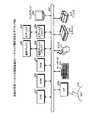
図1は、実施の形態1にかかる心臓モデルの断面描画例を示す説明図である。図1において、(A)は心臓の3次元モデルを示す。心臓の3次元モデルを、以下、「心臓モデル」と称す。心臓モデル100は、たとえば、テトラ要素と呼ばれる四面体の要素(非構造格子データ)の集合であり、各テトラ要素は、当該テトラ要素の配置位置に応じた物理値を持つ。物理値は、テトラ要素に対応する心筋の挙動を示す各種の値であり、たとえば、仕事力[KPa]や、仕事[J/ml]、仕事率[J/s・ml]が物理値に採用される。(Embodiment 1)
<Example of cross-section drawing of heart model>
FIG. 1 is an explanatory diagram of a cross-sectional drawing example of the heart model according to the first embodiment. In FIG. 1, (A) shows a three-dimensional model of the heart. Hereinafter, the three-dimensional model of the heart is referred to as a “heart model”. The
本実施の形態にかかる描画装置は、心臓モデル100に対し基準面を設定する。図1では例として、左心房と左心室との間にある僧帽弁の弁輪を含む面が基準面S1である。また、描画装置は、基準面S1上の視点からみて奥行側に、回転軸を設定する。そして、描画装置は、回転軸A周りに所定角度ずつ基準面S1を回転させた場合の断面を複数設定する。心臓モデル100の各断面は、心臓モデル100の左心室を構成するテトラ要素を通過した断面の集合となる。 The drawing apparatus according to the present embodiment sets a reference plane for the
なお、心臓モデル100の断面を「モデル断面」と称し、モデル断面がテトラ要素を通過した要素にできる断面を、「要素断面」と称す。モデル断面には、モデル断面を含むテトラ要素が持つ物理値が割り当てられる。描画装置は、レンダリング処理、すなわち、各モデル断面を、その内部の要素断面ごとに、当該要素断面が持つ物理値に応じた着色をおこなう。 A cross section of the
(B)は、視点から見た各モデル断面C1〜C3の描画状態を示す。各モデル断面C1〜C3では、要素断面に物理値に応じた着色が施されている。したがって、基準面S1から回転させた各モデル断面C1〜C3を表示することにより、視点P0からみて、手前側のモデル断面C1から奥行側のモデル断面C3に至るまでの物理値分布の変化が視認しやすくなる。 (B) shows the drawing state of each model cross section C1-C3 seen from the viewpoint. In each of the model cross sections C1 to C3, the element cross section is colored according to a physical value. Therefore, by displaying each of the model cross sections C1 to C3 rotated from the reference plane S1, a change in physical value distribution from the front model cross section C1 to the depth model cross section C3 is visually recognized from the viewpoint P0. It becomes easy to do.
(描画装置のハードウェア構成例)
図2は、実施の形態1にかかる描画装置のハードウェア構成例を示すブロック図である。図2において、描画装置は、CPU(Central Processing Unit)201と、ROM(Read Only Memory)202と、RAM(Random Access Memory)203と、磁気ディスクドライブ204と、磁気ディスク205と、光ディスクドライブ206と、光ディスク207と、ディスプレイ208と、I/F(Interface)209と、キーボード210と、マウス211と、スキャナ212と、プリンタ213と、を備えている。また、各構成部はバス200によってそれぞれ接続されている。(Hardware configuration example of drawing device)
FIG. 2 is a block diagram of a hardware configuration example of the drawing apparatus according to the first embodiment. In FIG. 2, a drawing apparatus includes a CPU (Central Processing Unit) 201, a ROM (Read Only Memory) 202, a RAM (Random Access Memory) 203, a
ここで、CPU201は、描画装置の全体の制御を司る。ROM202は、ブートプログラムなどのプログラムを記憶している。RAM203は、CPU201のワークエリアとして使用される。磁気ディスクドライブ204は、CPU201の制御にしたがって磁気ディスク205に対するデータのリード/ライトを制御する。磁気ディスク205は、磁気ディスクドライブ204の制御で書き込まれたデータを記憶する。 Here, the
光ディスクドライブ206は、CPU201の制御にしたがって光ディスク207に対するデータのリード/ライトを制御する。光ディスク207は、光ディスクドライブ206の制御で書き込まれたデータを記憶したり、光ディスク207に記憶されたデータをコンピュータに読み取らせたりする。 The optical disk drive 206 controls reading / writing of data with respect to the
ディスプレイ208は、カーソル、アイコンあるいはツールボックスをはじめ、文書、画像、機能情報などのデータを表示する表示装置である。このディスプレイ208は、たとえば、液晶ディスプレイ、プラズマディスプレイなどを採用することができる。 The display 208 is a display device that displays data such as a document, an image, and function information as well as a cursor, an icon, or a tool box. As the display 208, for example, a liquid crystal display, a plasma display, or the like can be adopted.
インターフェース(以下、「I/F」と略する。)209は、通信回線を通じてLAN(Local Area Network)、WAN(Wide Area Network)、インターネットなどのネットワーク214に接続され、このネットワーク214を介して他の装置に接続される。そして、I/F209は、ネットワーク214と内部のインターフェースを司り、外部装置からのデータの入出力を制御する。I/F209には、たとえばモデムやLANアダプタなどを採用することができる。 An interface (hereinafter abbreviated as “I / F”) 209 is connected to a network 214 such as a LAN (Local Area Network), a WAN (Wide Area Network), and the Internet through a communication line. Connected to other devices. The I /
キーボード210は、文字、数字、各種指示などの入力のためのキーを備え、データの入力をおこなう。また、タッチパネル式の入力パッドやテンキーなどであってもよい。マウス211は、カーソルの移動や範囲選択、あるいはウィンドウの移動やサイズの変更などをおこなう。ポインティングデバイスとして同様に機能を備えるものであれば、トラックボールやジョイスティックなどであってもよい。 The
スキャナ212は、画像を光学的に読み取り、描画装置内に画像データを取り込む。なお、スキャナ212は、OCR(Optical Character Reader)機能を持たせてもよい。また、プリンタ213は、画像データや文書データを印刷する。プリンタ213には、たとえば、レーザプリンタやインクジェットプリンタを採用することができる。なお、光ディスクドライブ206、光ディスク207、ディスプレイ208、キーボード210、マウス211、スキャナ212、およびプリンタ213の少なくともいずれか1つは、なくてもよい。 The
(描画装置の機能的構成例)
図3は、実施の形態1にかかる描画装置の機能的構成例を示すブロック図である。描画装置300は、取得部301と、設定部302と、割当部303と、描画部304と、を有する。取得部301、設定部302、割当部303、および、描画部304は、具体的には、たとえば、図2に示したRAM203、磁気ディスク205、光ディスク207などの記憶装置に記憶されたプログラムを、CPU201に実行させることによりその機能を実現する。(Example of functional configuration of drawing device)
FIG. 3 is a block diagram of a functional configuration example of the drawing apparatus according to the first embodiment. The
取得部301は、臓器の各位置に応じた物理値を有する要素の集合である臓器モデルを取得する。臓器モデルは、シミュレーションにより挙動が解析された3次元モデルであり、記憶装置に記憶される。取得部301は、具体的には、たとえば、臓器モデルとして上述した心臓モデル100を記憶装置から読み出す。 The
図4は、実施の形態1にかかる心臓モデル100のデータ構造例を示す説明図である。心臓モデル100は、ID項目と、第1頂点項目〜第4頂点項目と、重心項目と、物理値項目と、属性項目と、断面通過項目と、を有し、テトラ要素ごとに、各項目の値を有するデータ構造である。 FIG. 4 is an explanatory diagram of an example of a data structure of the
ID項目には、テトラ要素のID:i(iとテトラ要素の総数nはそれぞれ、1≦i≦nの関係を満たす整数)が格納される。IDとは、テトラ要素を一意に識別する識別情報である。ID:iのテトラ要素を、テトラ要素tiとする。第1頂点項目〜第4頂点項目には、テトラ要素tiの第1頂点v1(ti)〜第4頂点v4(ti)の頂点座標値が格納される。便宜上、座標値についても、v1(ti)〜v4(ti)と表記する。第1頂点v1(ti)〜第4頂点v4(ti)とは、四面体であるテトラ要素の各頂点である。 The ID item stores the ID of a tetra element: i (i and the total number n of tetra elements are integers satisfying a relationship of 1 ≦ i ≦ n, respectively). The ID is identification information that uniquely identifies the tetra element. A tetra element with ID: i is a tetra element ti. In the first vertex item to the fourth vertex item, vertex coordinate values of the first vertex v1 (ti) to the fourth vertex v4 (ti) of the tetra element ti are stored. For convenience, coordinate values are also expressed as v1 (ti) to v4 (ti). The first vertex v1 (ti) to the fourth vertex v4 (ti) are each vertex of a tetra element that is a tetrahedron.
重心項目には、テトラ要素tiの重心g(ti)となる重心座標値が格納される。便宜上、座標値についても、g(ti)と表記する。物理値項目には、テトラ要素tiに割り当てられた物理値e(ti)が格納される。上述したように、物理値は、テトラ要素に対応する心筋の挙動を示す値であり、たとえば、仕事力[KPa]や、仕事[J/ml]、仕事率[J/s・ml]が採用される。 The barycentric item stores the barycentric coordinate value that becomes the barycenter g (ti) of the tetra element ti. For convenience, the coordinate value is also expressed as g (ti). The physical value item stores a physical value e (ti) assigned to the tetra element ti. As described above, the physical value is a value indicating the behavior of the myocardium corresponding to the tetra element. For example, work power [KPa], work [J / ml], work rate [J / s · ml] is adopted. Is done.
属性項目には、テトラ要素tiの属性が格納される。属性の設定は任意とする。属性とは、テトラ要素tiの特徴を示す情報であり、たとえば、心臓のどの部位であるかを示す情報である。たとえば、テトラ要素tiが僧帽弁の弁輪に位置する場合には、弁輪であることを示す情報がテトラ要素tiの属性項目に格納される。したがって、弁輪を含む面を切り出したい場合には、属性項目を参照することにより、描画装置300は、弁輪のテトラ要素tiを含む要素群を抽出することができる。 The attribute item stores an attribute of the tetra element ti. Setting attributes is optional. The attribute is information indicating the characteristics of the tetra element ti, for example, information indicating which part of the heart it is. For example, when the tetra element ti is located on the annulus of the mitral valve, information indicating that it is an annulus is stored in the attribute item of the tetra element ti. Therefore, when it is desired to cut out the surface including the annulus, the
断面通過項目には、断面通過フラグが格納される。断面通過フラグとは、テトラ要素tiをモデル断面が通過したか否かを示す識別子である。本例では、断面通過フラグが「1」の場合はテトラ要素tiをモデル断面が通過したことを示し、「0」の場合はテトラ要素tiをモデル断面が通過していないことを示す。断面通過フラグは、設定部302により付与される情報である。 In the section passage item, a section passage flag is stored. The cross section passing flag is an identifier indicating whether or not the model cross section has passed through the tetra element ti. In this example, when the cross section flag is “1”, it indicates that the model cross section has passed through the tetra element ti, and when it is “0”, it indicates that the model cross section has not passed through the tetra element ti. The cross section passage flag is information given by the
図5は、実施の形態1にかかるテトラ要素tiを示す説明図である。テトラ要素tiの形状は第1頂点v1(ti)〜第4頂点v4(ti)を有する四面体である。また、重心g(ti)には、物理値e(ti)が割り当てられる。 FIG. 5 is an explanatory diagram of the tetra element ti according to the first embodiment. The shape of the tetra element ti is a tetrahedron having a first vertex v1 (ti) to a fourth vertex v4 (ti). A physical value e (ti) is assigned to the center of gravity g (ti).
図3に戻り、設定部302は、所定の視点P0からの視線方向と所定の角度をなす臓器モデルと交わる複数の平面を設定する。具体的には、設定部302は、設定した視点P0からの視線方向と鋭角をなす臓器モデルの断面を複数設定する。たとえば、基準面S1内において視線方向に直交する線分を回転軸Aとした場合、回転軸Aを基準として基準面S1を複数の異なる回転角度で回転させることにより、視線方向と鋭角をなす臓器モデルの断面を複数設定する。なお、視点P0の位置は、臓器モデルの内外を問わない。 Returning to FIG. 3, the
たとえば、図1に示したように、心臓モデル100の場合、描画装置300は、たとえば、弁輪と交わる面を基準面S1とする。描画装置300は、たとえば、心臓モデル100の属性項目を参照することにより抽出される要素群と交わる面を基準面S1とする。また、ユーザ操作により、設定してもよい。ユーザ操作の場合、描画装置300は、ユーザが任意に指定した3点を平面方程式に与えて解くことにより基準面S1を設定することができる。 For example, as illustrated in FIG. 1, in the case of the
そして、設定部302は、基準面S1を用いて回転軸Aを設定する。具体的には、たとえば、設定部302は、視点P0と基準面S1を結ぶ線分が基準面S1に対して直交する線分を、視点P0から基準面S1に向かう視線方向に設定する。このあと、設定部302は、視線方向と鋭角をなすモデル断面を複数設定する。なお、視点P0は、臓器モデルの外部または臓器モデルの内部のいずれに設定してもよい。 Then, the
図6は、実施の形態1にかかる設定部302によるモデル断面の設定例を示す説明図である。(A)は、弁輪600を含む基準面S1を示す。(B)は、視線方向の設定を示す。(A)により基準面S1を設定したあと、描画装置300は、視点P0から基準面S1に向かい、基準面S1に直交する線分を視線方向に設定する。具体的には、たとえば、心臓内部の心筋の状態を視認したいので、設定部302は、基準面S1の弁輪600において最も視点P0から離れている点P1を検出する。そして、設定部302は、視点P0から基準面S1に向かい、検出した点P1から所定距離d0離れた位置で基準面S1に直交する点P2を検出する。そして、設定部302は、視点P0を始点とし点P2を終点とするベクトルを視線方向ベクトルVに設定する。視線方向ベクトルVが指し示す方向が視線方向となる。視線方向ベクトルVと基準面S1とのなす角度α0は鋭角となる。 FIG. 6 is an explanatory diagram of an example of setting a model cross section by the
(C)また、設定部302は、回転軸A周りに基準面S1を回転させた位置となるモデル断面を設定する。モデル断面の枚数および回転軸Aの回転角は、たとえば、ユーザ操作により設定される。(C)の場合は、モデル断面の枚数は3枚、回転角はθ1〜θ3に設定される。また、各モデル断面C1〜C3と視線方向ベクトルVとのなす角度α1〜α3は鋭角に設定される。これにより、各モデル断面C1〜C3が視点P0から視認しやすい状態で表示されることになる。なお、設定部302は、モデル断面C1〜C3と交わるテトラ要素tiの断面通過フラグを「0」から「1」に設定する。これにより、モデル断面をと交わるテトラ要素tiが特定できることになる。 (C) In addition, the
図3に戻り、割当部303は、要素の集合のうち、設定された複数の平面と交わる要素に対応する物理値を、複数の平面が臓器モデルの要素とそれぞれ交わる面である複数の要素の断面に割り当てる。割当部303は、具体的には、要素の集合のうち、断面と交わる特定の要素が有する物理値を、臓器モデルの断面が特定の要素と交わることにより得られる特定の要素の断面に割り当てる。割当部303は、たとえば、心臓モデル100を構成するテトラ要素群のうち、モデル断面C1〜C3と交わる特定のテトラ要素、すなわち、断面通過フラグが「1」であるテトラ要素tiを、心臓モデル100のデータ構造から特定する。つぎに、割当部303は、モデル断面C1〜C3が特定のテトラ要素を通過した場合に形成される要素断面を検出する。 Returning to FIG. 3, the assigning
図7は、実施の形態1にかかる要素断面の検出例1を示す説明図である。図7において、割当部303は、あるモデル断面Ck(kはモデル断面の番号)がテトラ要素tiと交わる要素断面ckjを検出する。jは要素断面の番号である。要素断面ckjは、第1頂点u1(ckj)〜第3頂点u3(ckj)を有する三角形である。要素断面ckjには、検出元のテトラ要素tiの物理値e(ti)が割り当てられる。 FIG. 7 is an explanatory diagram of a first example of element cross-section detection according to the first embodiment. In FIG. 7, the assigning
図8は、実施の形態1にかかる要素断面の検出例2を示す説明図である。図8において、割当部303は、あるモデル断面Ckがテトラ要素tiと交わる要素断面ckjを検出する。jは要素断面の番号である。図8の例では、要素断面ckjの形状は四角形である。この場合、要素断面ckjを2つの三角形の要素断面ckj1、ckj2に分割する。要素断面ckj1は、第1頂点u11(ckj)〜第3頂点u31(ckj)を有する三角形である。要素断面ckj2は、第1頂点u12(ckj)〜第3頂点u32(ckj)を有する三角形である。要素断面ckj1,ckj2には、ともに、検出元のテトラ要素tiの物理値e(ti)が割り当てられる。このように、要素断面ckjを分割することにより、モデル断面の解像度が向上する。 FIG. 8 is an explanatory diagram of a second example of element cross-section detection according to the first embodiment. In FIG. 8, the assigning
また、描画部304は、対応する物理値が割り当てられた臓器モデル100の複数の要素の断面を、対応する物理値に基づいて描画する。具体的には、たとえば、描画部304は、三角形状のポリゴンを処理単位として法線を求め着色をおこなうレンダリング処理を実行する。したがって、要素断面を三角形状にすることにより、既存のレンダリング処理を採用することができる。 In addition, the
図9は、実施の形態1にかかる要素断面のデータ構造例を示す説明図である。要素断面は、ID項目、第1頂点項目〜第3頂点項目、物理値項目を有し、要素断面ごとに、各項目の値を有するデータ構造である。 FIG. 9 is an explanatory diagram of an example of the data structure of the element cross section according to the first embodiment. The element cross section has an ID item, a first vertex item to a third vertex item, and a physical value item, and is a data structure having a value of each item for each element cross section.
ID項目には、要素断面のID:j(jと後述するモデル断面Ck内の要素断面の総数mkとはそれぞれ、1≦j≦mkの関係を満たす整数)が格納される。kは、要素断面を有するモデル断面Ckを識別する番号である。mkは、モデル断面Ck内の要素断面の総数である。IDとは、要素断面を一意に識別する識別情報である。モデル断面Ck内のID:jの要素断面を、要素断面ckjとする。第1頂点項目〜第3頂点項目には、要素断面ckjの第1頂点u1(ckj)〜第3頂点u3(ckj)の頂点座標値が格納される。便宜上、座標値についても、u1(ckj)〜u3(ckj)と表記する。第1頂点u1(ckj)〜第3頂点u3(ckj)とは、三角形である要素断面ckjの各頂点である。物理値項目には、要素断面ckjに対応する物理値e(ckj)が格納される。たとえば、要素断面ckjが検出されたテトラ要素tiに割り当てられた物理値e(ti)が物理値e(ckj)として格納される。 In the ID item, element cross section ID: j (j and the total number mk of element cross sections in a model cross section Ck described later are integers satisfying the relationship of 1 ≦ j ≦ mk, respectively) is stored. k is a number for identifying a model cross section Ck having an element cross section. mk is the total number of element cross sections in the model cross section Ck. The ID is identification information for uniquely identifying the element cross section. The element cross section with ID: j in the model cross section Ck is defined as an element cross section ckj. In the first to third vertex items, vertex coordinate values of the first vertex u1 (ckj) to the third vertex u3 (ckj) of the element cross section ckj are stored. For convenience, coordinate values are also expressed as u1 (ckj) to u3 (ckj). The first vertex u1 (ckj) to the third vertex u3 (ckj) are each vertex of the element cross section ckj that is a triangle. The physical value item stores a physical value e (ckj) corresponding to the element cross section ckj. For example, the physical value e (ti) assigned to the tetra element ti in which the element cross section ckj is detected is stored as the physical value e (ckj).
描画部304は、特定の要素の物理値が特定の要素の断面に割り当てられた臓器モデルの各断面を、特定の要素の物理値に基づいて描画する。具体的には、たとえば、描画部304は、要素断面ckjを有するモデル断面Ckを、要素断面ckjに割り当てられた物理値によりレンダリングする。具体的には、描画部304は、記憶装置に記憶されているカラーマップを参照してレンダリングを実行する。 The
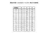
図10は、実施の形態1にかかるカラーマップの一例を示す説明図である。カラーマップには、物理値ごとにR(赤)、G(緑)、B(青)の3原色の値が設定されている。カラーマップの物理値は、実際の物理値そのものでもよく、実際の物理値を正規化した値でもよい。たとえば、仕事力の場合は、0〜200[kPa]の範囲をとるため、カラーマップの物理値の範囲[0〜10]に対応付けて正規化される。仕事(たとえば、−0.18〜0.09[J/ml])や仕事率(たとえば、−10〜110[J・S・ml])の場合も同様である。描画部304は、カラーマップを参照して、要素断面ckjごとに該当するRGBの値を抽出して、レンダリングを実行する。これにより、図1の(B)に示したようなモデル断面が表示される。 FIG. 10 is an explanatory diagram of an example of a color map according to the first embodiment. In the color map, values of three primary colors R (red), G (green), and B (blue) are set for each physical value. The physical value of the color map may be an actual physical value itself or a value obtained by normalizing the actual physical value. For example, in the case of work power, since it takes a range of 0 to 200 [kPa], it is normalized in association with a physical value range [0 to 10] of the color map. The same applies to work (for example, −0.18 to 0.09 [J / ml]) and work rate (for example, −10 to 110 [J · S · ml]). The
<描画処理手順>
図11は、実施の形態1にかかる描画処理手順例を示すフローチャートである。まず、描画装置300は、取得部301により心臓モデル100などの臓器モデルを取得し(ステップS1101)、設定部302により、モデル断面を設定する(ステップS1102)。そして、描画装置300は、未選択のモデル断面があるか否かを判断する(ステップS1103)。未選択のモデル断面がある場合(ステップS1103:Yes)、描画装置300は、未選択のモデル断面を1つ選択する(ステップS1104)。そして、描画装置300は、選択モデル断面と交わる未選択のテトラ要素tiがあるか否かを判断する(ステップS1105)。未選択のテトラ要素tiがある場合(ステップS1105:Yes)、描画装置300は、未選択のテトラ要素tiを1つ選択する(ステップS1106)。<Drawing procedure>
FIG. 11 is a flowchart of a drawing processing procedure example according to the first embodiment. First, the
そして、描画装置300は、選択テトラ要素tiでの要素断面を検出する(ステップS1107)。描画装置300は、検出した要素断面の形状が三角形であるか否かを判断する(ステップS1108)。三角形である場合(ステップS1108:Yes)、ステップS1110に移行する。一方、三角形でない場合(ステップS1108:No)、描画装置300は、四角形である要素断面を、2つの三角形に分割して(ステップS1109)、ステップS1110に移行する。このように、三角形状の要素断面が検出されると、図9に示した要素断面のデータ構造が構築されることになる。 Then, the
ステップS1110において、描画装置300は、割当部303により、選択テトラ要素tiの物理値を、三角形の要素断面に割り当てる(ステップS1110)。具体的には、描画装置300は、要素断面のデータ構造において、検出した要素断面のレコードに、選択テトラ要素tiの物理値を格納する。このあと、ステップS1105に戻る。 In step S1110, the
ステップS1105において、選択モデル断面と交わる未選択テトラ要素tiがない場合(ステップS1105:No)、描画装置300は、ステップS1103に戻る。ステップS1103において、未選択のモデル断面がない場合(ステップS1103:No)、各モデル断面を構成する要素断面の各々に物理値が割り当てられたことになる。したがって、描画装置300は、描画部304により、レンダリング処理を実行する(ステップS1111)。これにより、図1の(B)に示したように、視点P0からの各モデル断面が表示されることになる。 In step S1105, when there is no unselected tetra element ti that intersects the selected model cross section (step S1105: No), the
(実施の形態2)
<心臓モデル100の断面描画例>
つぎに、実施の形態2について説明する。実施の形態1では、回転軸Aから基準面S1を回転させることにより、複数のモデル断面を設定したが、実施の形態2では、複数の互いに平行なモデル断面を設定する。たとえば、上述した心臓モデル100の場合、各モデル断面の物理値の連続性が確認しやすくなる。なお、モデル断面の設定以外の構成および処理については、実施の形態1と同一であるため説明を省略する。(Embodiment 2)
<Example of cross-sectional drawing of
Next, a second embodiment will be described. In the first embodiment, a plurality of model cross sections are set by rotating the reference plane S1 from the rotation axis A. However, in the second embodiment, a plurality of parallel model cross sections are set. For example, in the case of the
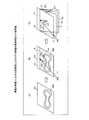
図12は、心臓モデル100の断面描画例を示す説明図である。図12において、(A)は心臓モデル100を示す。描画装置300は、心臓モデル100に対し基準面S2を設定する。図12では例として、上下方向に心臓モデル100と交わる断面が基準面S2である。基準面S2は、心尖部1200と交わる断面とする。複数のモデル断面C1〜C3は、基準面S2に基づいて設定される。設定方法については後述する。 FIG. 12 is an explanatory diagram illustrating a cross-sectional drawing example of the
(B)は、視点P0から見た各モデル断面C1〜C3の描画状態を示す。各モデル断面C1〜C3では、要素断面に物理値に応じた色が施されている。したがって、基準面S2の回転方向に沿って各モデル断面C1〜C3を表示することにより、各モデル断面C1〜C3の物理値の連続性が確認しやすくなる。 (B) shows a drawing state of each of the model cross sections C1 to C3 viewed from the viewpoint P0. In each of the model cross sections C1 to C3, the element cross section is colored according to the physical value. Therefore, by displaying the model cross sections C1 to C3 along the rotation direction of the reference plane S2, the continuity of the physical values of the model cross sections C1 to C3 can be easily confirmed.
図13は、基準面S1の設定方法を示す説明図である。図13において、符号1301は、僧帽弁であり、符号1302は大動脈弁である。僧帽弁1301、大動脈弁1302、心尖部1200は、テトラ要素tiにおいてそれぞれ属性として設定されている場合は、設定部302により自動的に設定可能である。また、設定部302は、ユーザ操作により、僧帽弁1301、大動脈弁1302、心尖部1200を示すデータを設定することとしてもよい。 FIG. 13 is an explanatory diagram showing a method for setting the reference plane S1. In FIG. 13,
符号1310は、僧帽弁1301の重心であり、符号1320は大動脈弁1302の重心である。僧帽弁1301の重心1310は、設定部302が、僧帽弁1301を構成するテトラ要素群の座標値により計算してもよく、ユーザ操作により設定することとしてもよい。また、大動脈弁1302の重心1320についても同様である。また、符号1330は、僧帽弁1301の重心1310と大動脈弁1302の重心1320とを結ぶ線分L1の2等分点である。2等分点1330は、設定部302により、僧帽弁1301の重心1310と大動脈弁1302の重心1320により算出される。そして、心尖部1200と2等分点1330とを通り、かつ、線分L1に直交する面が基準面S2となる。また、心尖部1200と2等分点1330とを通る線分L0が心軸、すなわち、心臓の血流方向に相当する。
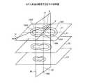
図14は、モデル断面の設定方法を示す説明図である。図14では、モデル断面の枚数を3枚とする。描画装置300では、設定部302により、モデル断面C1〜C3の姿勢を決める2つの角度θ、φが設定される。θは、モデル断面C1〜C3内の第1線分と基準面S1内の線分とのなす角度であり、例として直角とする。第1線分とは、僧帽弁1301の重心1310と大動脈弁1302の重心1320とを通過する線分L1である。 FIG. 14 is an explanatory diagram showing a method for setting a model cross section. In FIG. 14, the number of model cross sections is three. In the
基準面S2内の線分とは、心尖部1200と2等分点1330とを通過する線分L0である。φは、基準面S2内の線分L0とモデル断面C1〜C3内の第2線分L2とのなす角度である。第2線分L2とは、第1線分L1に直交し、かつ、第1線分L1と基準面S2内の線分L0との交点を通過する線分である。θおよびφは、ユーザ操作により設定可能である。なお、θおよびφは、各モデル断面C1〜C3に共通の値であるため、各モデル断面C1〜C3は平行となる。また、隣接するモデル断面の間隔は等間隔とする。モデル断面の間隔もユーザ操作により設定可能である。 The line segment in the reference plane S2 is a line segment L0 that passes through the
モデル断面C1〜C3は、φを調整することにより視線方向と鋭角をなす。具体的には、視点P0と視線方向が決まっている状態では、視線方向とモデル断面C1〜C3とのなす角度αが鋭角となるように、φを設定すればよい。このようにモデル断面C1〜C3を設定することにより、図12の(B)に示したように、各モデル断面を表示することができる。 The model cross sections C1 to C3 form an acute angle with the line-of-sight direction by adjusting φ. Specifically, in a state where the viewpoint P0 and the line-of-sight direction are determined, φ may be set so that the angle α formed between the line-of-sight direction and the model cross sections C1 to C3 becomes an acute angle. By setting the model cross sections C1 to C3 in this way, each model cross section can be displayed as shown in FIG.
このように、実施の形態1、2によれば、臓器における連続的な物理値分布の視認性の向上を図ることができる。また、臓器を通過する複数のモデル断面を設定し、モデル断面上に物理値を表示することにより、ユーザにとって複数のモデル断面全体の分布がつかみやすくなる。また、各モデル断面を臓器の構造に合わせて設定することにより、効率よく観察することが可能となる。 As described above, according to the first and second embodiments, it is possible to improve the visibility of a continuous physical value distribution in an organ. In addition, by setting a plurality of model cross sections that pass through the organ and displaying physical values on the model cross section, the distribution of the entire model cross sections can be easily grasped by the user. In addition, by setting each model cross section according to the structure of the organ, it becomes possible to observe efficiently.
具体的には、心臓において、血流の方向は、拡張期においては僧帽弁から心尖部方向、拍出期においては心尖部から大動脈弁の方向となる。したがって、血流の方向と直交するモデル断面を複数設定することにより、体の前面側に開いたようにモデル断面を展開することができる。正面から、たとえば、視線方向から観察する場合、視線方向とモデル断面とのなす角度が鋭角となり、複数のモデル断面全体の分布を観察し易い状態で表示することができる。 Specifically, in the heart, the direction of blood flow is from the mitral valve to the apex during diastole and from the apex to the aortic valve during stroke. Therefore, by setting a plurality of model cross sections orthogonal to the direction of blood flow, the model cross sections can be developed so as to open to the front side of the body. When observing from the front, for example, from the line-of-sight direction, the angle formed by the line-of-sight direction and the model cross section becomes an acute angle, and the distribution of the entire model cross section can be displayed in an easily observable state.
また、要素断面の形状が四角形の場合、2個の三角形に分割することにより、モデル断面での解像度の向上を図ることができる。また、要素断面を三角形状にすることにより、既存のレンダリング処理を採用することができる。したがって、レンダリング処理を修正する必要がなく、レンダリング処理を効率的に実行することができる。 Further, when the shape of the element cross section is a quadrangle, the resolution of the model cross section can be improved by dividing the element cross section into two triangles. Further, existing rendering processing can be adopted by making the element cross section triangular. Therefore, it is not necessary to modify the rendering process, and the rendering process can be executed efficiently.
以上説明したように、描画プログラム、描画方法、および、描画装置によれば、臓器における連続的な物理値分布の視認性の向上を図ることができる。 As described above, according to the drawing program, the drawing method, and the drawing apparatus, it is possible to improve the visibility of the continuous physical value distribution in the organ.
100 心臓モデル
300 描画装置
301 取得部
302 設定部
303 割当部
304 描画部
C1〜C3 モデル断面DESCRIPTION OF
Claims (7)
Translated fromJapanese臓器の各位置に応じた物理値を有する要素の集合である臓器モデルを取得させ、
所定の視点位置からの視線方向と所定の角度をなす前記臓器モデルと交わる複数の平面を設定させ、
設定された前記複数の平面が前記臓器モデルの要素とそれぞれ交わる面である複数の要素の断面の形状が四角形である場合、前記四角形の形状の前記要素の断面を2個の三角形に分割させ、
前記要素の集合のうち、前記複数の平面と交わる要素に対応する物理値を、前記複数の要素の断面に割り当てさせ、分割された2個の三角形の形状の要素の断面の各々に、分割前の前記四角形の形状の前記要素の断面の物理値を割り当てさせ、
前記対応する物理値が割り当てられた前記臓器モデルの前記複数の要素の断面を、前記対応する物理値に基づいて描画させる、ことを特徴とする描画プログラム。On the computer,
Obtain an organ model that is a set of elements having physical values according to each position of the organ;
A plurality of planes intersecting with the organ model that forms a predetermined angle with a line-of-sight direction from a predetermined viewpoint position;
When the cross-sectional shape of the plurality of elements, each of which is a plane where the plurality of set planes intersect with the elements of the organ model, is a quadrilateral, the cross-section of the element having the quadrangular shape is divided into two triangles,
Of said set ofelements, the physical value corresponding to the intersection with theprevious SL plurality of planar elements, before let assigned to the cross section ofKifuku number of elements,to each of the cross-section of the elements of the shape of the divided two triangles , Assign the physical value of the cross-section of the element of the square shape before the division,
A drawing program for causing a section of the plurality of elements of the organ model to which the corresponding physical value is assigned to be drawn based on the corresponding physical value.
前記コンピュータに、
前記複数の平面を設定させる場合、
前記臓器モデルと交わり前記視線方向と所定の角度をなす基準面内において前記視線方向に直交する線分を回転軸として前記基準面を複数の異なる回転角度で回転させて、前記視線方向と所定の角度をなす複数の平面を設定させることを特徴とする請求項1に記載の描画プログラム。The drawing program is
In the computer,
When setting the plurality of planes,
The reference plane is rotated at a plurality of different rotation angles about a line segment orthogonal to the line-of-sight direction within a reference plane that intersects the organ model and forms a predetermined angle with the line-of-sight direction. The drawing program according to claim 1, wherein a plurality of planes forming an angle are set.
前記描画プログラムは、
前記コンピュータに、
前記心臓の弁輪を通過する面を前記基準面として、前記視線方向と所定の角度をなす複数の平面を設定させることを特徴とする請求項2に記載の描画プログラム。The organ model is a heart organ model;
The drawing program is
In the computer,
The drawing program according to claim 2, wherein a plane that passes through the annulus of the heart is set as the reference plane, and a plurality of planes that form a predetermined angle with the line-of-sight direction are set.
前記コンピュータに、
前記臓器モデルと交わる基準面に直交し前記視線方向と所定の角度をなす複数の平面を設定させることを特徴とする請求項1に記載の描画プログラム。The drawing program is
In the computer,
The drawing program according to claim 1, wherein a plurality of planes orthogonal to a reference plane intersecting the organ model and having a predetermined angle with the line-of-sight direction are set.
前記描画プログラムは、
前記コンピュータに、
前記心臓の血流方向となる線分を含む面を前記基準面として、前記視線方向と所定の角度をなす複数の平面を設定させることを特徴とする請求項4に記載の描画プログラム。The organ model is a heart organ model;
The drawing program is
In the computer,
The drawing program according to claim 4, wherein a plurality of planes that form a predetermined angle with the line-of-sight direction are set with a plane including a line segment that is a blood flow direction of the heart as the reference plane.
臓器の各位置に応じた物理値を有する要素の集合である臓器モデルを取得し、Obtain an organ model that is a set of elements with physical values according to each position of the organ,
所定の視点位置からの視線方向と所定の角度をなす前記臓器モデルと交わる複数の平面を設定し、Setting a plurality of planes intersecting the organ model that forms a predetermined angle with the line-of-sight direction from a predetermined viewpoint position;
設定された前記複数の平面が前記臓器モデルの要素とそれぞれ交わる面である複数の要素の断面の形状が四角形である場合、前記四角形の形状の前記要素の断面を2個の三角形に分割し、When the cross-sectional shape of the plurality of elements, each of which is a plane where the plurality of set planes intersect with the elements of the organ model, is a quadrilateral, the cross-section of the element having the quadrangular shape is divided into two triangles,
前記要素の集合のうち、前記複数の平面と交わる要素に対応する物理値を、前記複数の要素の断面に割り当て、分割された2個の三角形の形状の要素の断面の各々に、分割前の前記四角形の形状の前記要素の断面の物理値を割り当て、Of the set of elements, physical values corresponding to elements intersecting with the plurality of planes are assigned to the cross-sections of the plurality of elements, and each of the two triangular-shaped element cross-sections before the division is assigned. Assign a physical value of the cross-section of the element of the square shape;
前記対応する物理値が割り当てられた前記臓器モデルの前記複数の要素の断面を、前記対応する物理値に基づいて描画させる、ことを特徴とする描画方法。A drawing method, characterized in that cross-sections of the plurality of elements of the organ model to which the corresponding physical values are assigned are drawn based on the corresponding physical values.
所定の視点位置からの視線方向と所定の角度をなす前記臓器モデルと交わる複数の平面を設定する設定部と、A setting unit that sets a plurality of planes that intersect with the organ model that forms a predetermined angle with a line-of-sight direction from a predetermined viewpoint position;
設定された前記複数の平面が前記臓器モデルの要素とそれぞれ交わる面である複数の要素の断面の形状が四角形である場合、前記四角形の形状の前記要素の断面を2個の三角形に分割する分割部と、Division of dividing the cross section of the quadrilateral element into two triangles when the cross section shape of the plurality of elements is a plane where the set planes intersect with the organ model element, respectively. And
前記要素の集合のうち、前記複数の平面と交わる要素に対応する物理値を、前記複数の要素の断面に割り当て、分割された2個の三角形の形状の要素の断面の各々に、分割前の前記四角形の形状の前記要素の断面の物理値を割り当てる割当部と、Of the set of elements, physical values corresponding to elements intersecting with the plurality of planes are assigned to the cross-sections of the plurality of elements, and each of the two triangular-shaped element cross-sections before the division is assigned. An assigning unit for assigning a physical value of a cross section of the element having the rectangular shape;
前記対応する物理値が割り当てられた前記臓器モデルの前記複数の要素の断面を、前記対応する物理値に基づいて描画する描画部と、A drawing unit for drawing a cross section of the plurality of elements of the organ model to which the corresponding physical value is assigned based on the corresponding physical value;
を有することを特徴とする描画装置。A drawing apparatus comprising:
Priority Applications (4)
| Application Number | Priority Date | Filing Date | Title |
|---|---|---|---|
| JP2012131243AJP5988088B2 (en) | 2012-06-08 | 2012-06-08 | Drawing program, drawing method, and drawing apparatus |
| EP13170627.7AEP2672457A3 (en) | 2012-06-08 | 2013-06-05 | Rendering program, rendering method, and rendering apparatus |
| US13/911,598US9864836B2 (en) | 2012-06-08 | 2013-06-06 | Computer product, rendering apparatus, and rendering method |
| US13/911,578US9767252B2 (en) | 2012-06-08 | 2013-06-06 | Computer product, rendering method, and rendering apparatus |
Applications Claiming Priority (1)
| Application Number | Priority Date | Filing Date | Title |
|---|---|---|---|
| JP2012131243AJP5988088B2 (en) | 2012-06-08 | 2012-06-08 | Drawing program, drawing method, and drawing apparatus |
Publications (2)
| Publication Number | Publication Date |
|---|---|
| JP2013252395A JP2013252395A (en) | 2013-12-19 |
| JP5988088B2true JP5988088B2 (en) | 2016-09-07 |
Family
ID=48700268
Family Applications (1)
| Application Number | Title | Priority Date | Filing Date |
|---|---|---|---|
| JP2012131243AActiveJP5988088B2 (en) | 2012-06-08 | 2012-06-08 | Drawing program, drawing method, and drawing apparatus |
Country Status (3)
| Country | Link |
|---|---|
| US (2) | US9767252B2 (en) |
| EP (1) | EP2672457A3 (en) |
| JP (1) | JP5988088B2 (en) |
Families Citing this family (2)
| Publication number | Priority date | Publication date | Assignee | Title |
|---|---|---|---|---|
| JP5907502B2 (en)* | 2012-06-08 | 2016-04-26 | 富士通株式会社 | Display program, display method, and display device |
| EP3403451B1 (en) | 2016-01-14 | 2019-11-06 | British Telecommunications public limited company | Cellular telecommunications network |
Family Cites Families (27)
| Publication number | Priority date | Publication date | Assignee | Title |
|---|---|---|---|---|
| US5458126A (en)* | 1994-02-24 | 1995-10-17 | General Electric Company | Cardiac functional analysis system employing gradient image segmentation |
| US6694163B1 (en) | 1994-10-27 | 2004-02-17 | Wake Forest University Health Sciences | Method and system for producing interactive, three-dimensional renderings of selected body organs having hollow lumens to enable simulated movement through the lumen |
| US5889524A (en)* | 1995-09-11 | 1999-03-30 | University Of Washington | Reconstruction of three-dimensional objects using labeled piecewise smooth subdivision surfaces |
| US6301496B1 (en)* | 1998-07-24 | 2001-10-09 | Biosense, Inc. | Vector mapping of three-dimensionally reconstructed intrabody organs and method of display |
| JP2003141566A (en)* | 2001-11-07 | 2003-05-16 | Kansai Tlo Kk | Method of simulation for cutting three-dimensional object |
| US7397937B2 (en) | 2001-11-23 | 2008-07-08 | R2 Technology, Inc. | Region growing in anatomical images |
| US20030169911A1 (en)* | 2001-12-11 | 2003-09-11 | Snyder Gregory B. | Method and apparatus for processing and displaying images of the arteries and veins |
| US20040130546A1 (en)* | 2003-01-06 | 2004-07-08 | Porikli Fatih M. | Region growing with adaptive thresholds and distance function parameters |
| US7175656B2 (en)* | 2003-04-18 | 2007-02-13 | Alexander Khairkhahan | Percutaneous transcatheter heart valve replacement |
| US20070014452A1 (en)* | 2003-12-01 | 2007-01-18 | Mitta Suresh | Method and system for image processing and assessment of a state of a heart |
| US20060034513A1 (en)* | 2004-07-23 | 2006-02-16 | Siemens Medical Solutions Usa, Inc. | View assistance in three-dimensional ultrasound imaging |
| JP4518389B2 (en)* | 2004-11-25 | 2010-08-04 | 本田技研工業株式会社 | System and program for generating and displaying two-dimensional data from three-dimensional data |
| WO2006067719A2 (en)* | 2004-12-20 | 2006-06-29 | Koninklijke Philips Electronics N.V. | A method, a system and a computer program for integration of medical diagnostic information and a geometric model of a movable body |
| DE102005046203B3 (en)* | 2005-09-27 | 2007-01-04 | Siemens Ag | Diagnostic picture data selectively representing method, involves determining three-dimensional picture information, and subdividing determined information into representative and non-representative unit data values |
| WO2008047766A1 (en)* | 2006-10-17 | 2008-04-24 | Shoji Yamamoto | Cardiac performance simulation system, cardiac performance simulation method, cardiac performance simulation program and composite material sheet |
| US9275190B2 (en)* | 2007-04-23 | 2016-03-01 | Siemens Aktiengesellschaft | Method and system for generating a four-chamber heart model |
| US8718944B2 (en)* | 2007-05-22 | 2014-05-06 | Worcester Polytechnic Institute | Patient-specific image-based computational modeling and techniques for human heart surgery optimization |
| JP5523681B2 (en)* | 2007-07-05 | 2014-06-18 | 株式会社東芝 | Medical image processing device |
| WO2009029386A1 (en)* | 2007-08-02 | 2009-03-05 | Neuro Diagnostic Devices, Inc. | Non-invasive intracranial pressure sensor |
| EP2051205B1 (en)* | 2007-10-17 | 2012-03-14 | Deutsches Krebsforschungszentrum | Method, computer program and workstation for removing undesirable objects for a digital medical image |
| JP5241357B2 (en)* | 2008-07-11 | 2013-07-17 | 三菱プレシジョン株式会社 | Biological data model creation method and apparatus |
| AU2009295315A1 (en)* | 2008-09-25 | 2010-04-01 | Cae Healthcare Inc. | Simulation of medical imaging |
| US8948476B2 (en)* | 2010-12-20 | 2015-02-03 | St. Jude Medical, Atrial Fibrillation Division, Inc. | Determination of cardiac geometry responsive to doppler based imaging of blood flow characteristics |
| WO2011142222A1 (en)* | 2010-05-10 | 2011-11-17 | 株式会社 日立メディコ | Image processing device and image processing method |
| US8315812B2 (en)* | 2010-08-12 | 2012-11-20 | Heartflow, Inc. | Method and system for patient-specific modeling of blood flow |
| DE102010043849B3 (en)* | 2010-11-12 | 2012-02-16 | Siemens Aktiengesellschaft | Device for determining and representing blood circulation of heart muscle, of computer tomography system, has stimulation unit that stimulates blood flow in different regions of heart muscle and determines blood circulation of heart muscle |
| JP5866177B2 (en)* | 2011-11-10 | 2016-02-17 | ソニー株式会社 | Image processing apparatus and image processing method |
- 2012
- 2012-06-08JPJP2012131243Apatent/JP5988088B2/enactiveActive
- 2013
- 2013-06-05EPEP13170627.7Apatent/EP2672457A3/ennot_activeCeased
- 2013-06-06USUS13/911,578patent/US9767252B2/enactiveActive
- 2013-06-06USUS13/911,598patent/US9864836B2/enactiveActive
Also Published As
| Publication number | Publication date |
|---|---|
| US9767252B2 (en) | 2017-09-19 |
| US20130332126A1 (en) | 2013-12-12 |
| US9864836B2 (en) | 2018-01-09 |
| EP2672457A3 (en) | 2017-05-03 |
| EP2672457A2 (en) | 2013-12-11 |
| JP2013252395A (en) | 2013-12-19 |
| US20130328868A1 (en) | 2013-12-12 |
Similar Documents
| Publication | Publication Date | Title |
|---|---|---|
| JP4323472B2 (en) | Polygon chart drawing processing method and program | |
| US10810794B2 (en) | Method and apparatus for 3D clothing draping simulation | |
| NO20111166A1 (en) | Three-dimensional visualization of images of the earth's surface | |
| JP2008521462A (en) | 2D / 3D integrated contour editor | |
| CA2775241A1 (en) | Drawing graphical objects in a 3d subsurface environment | |
| US8004539B2 (en) | Systems and methods for improved graphical parameter definition | |
| KR20210021933A (en) | Methode and apparatus of measuring measurement of two dimensional pattern corresponding to three dimensional virtual clothing | |
| JP5988088B2 (en) | Drawing program, drawing method, and drawing apparatus | |
| US11941775B2 (en) | Three-dimensional folding tool | |
| JP2016100016A (en) | Image segmentation | |
| JP6972647B2 (en) | 3D shape data editing device and 3D shape data editing program | |
| Kelly et al. | Interactive dimensioning of parametric models | |
| JP7132921B2 (en) | Dynamic dimension switching for 3D content based on viewport resize | |
| CN115730157A (en) | Method and system for rapidly displaying lines of dwg drawing in Web | |
| JP2012027793A (en) | Image processing system and image processing system control method and program | |
| JP5892548B2 (en) | Drawing program, drawing apparatus, and drawing method | |
| JP5904544B2 (en) | Visualization program, visualization method, and visualization apparatus | |
| JP2023083110A (en) | Information processing apparatus, information processing method, and program | |
| US20140300604A1 (en) | Vector graphics authoring tool that enables directional input requests for selecting reference points on a vector path of an image being authored | |
| US7046241B2 (en) | Oriented three-dimensional editing glyphs | |
| JP2007213437A (en) | Information processing method and information processing apparatus | |
| US12299784B2 (en) | Floor plan extraction | |
| JP3851014B2 (en) | Effective visual field verification device, effective visual field verification method, and computer-readable recording medium | |
| Arora | Creative visual expression in immersive 3D environments | |
| JPH11194864A (en) | Information presenting device and computer-readable recording medium recording information presentation program |
Legal Events
| Date | Code | Title | Description |
|---|---|---|---|
| A621 | Written request for application examination | Free format text:JAPANESE INTERMEDIATE CODE: A621 Effective date:20150205 | |
| A977 | Report on retrieval | Free format text:JAPANESE INTERMEDIATE CODE: A971007 Effective date:20151021 | |
| A131 | Notification of reasons for refusal | Free format text:JAPANESE INTERMEDIATE CODE: A131 Effective date:20151110 | |
| A521 | Written amendment | Free format text:JAPANESE INTERMEDIATE CODE: A523 Effective date:20160112 | |
| TRDD | Decision of grant or rejection written | ||
| A01 | Written decision to grant a patent or to grant a registration (utility model) | Free format text:JAPANESE INTERMEDIATE CODE: A01 Effective date:20160628 | |
| A61 | First payment of annual fees (during grant procedure) | Free format text:JAPANESE INTERMEDIATE CODE: A61 Effective date:20160727 | |
| R150 | Certificate of patent or registration of utility model | Ref document number:5988088 Country of ref document:JP Free format text:JAPANESE INTERMEDIATE CODE: R150 |