JP5986637B2 - Chemical solution administration device - Google Patents
Chemical solution administration deviceDownload PDFInfo
- Publication number
- JP5986637B2 JP5986637B2JP2014538167AJP2014538167AJP5986637B2JP 5986637 B2JP5986637 B2JP 5986637B2JP 2014538167 AJP2014538167 AJP 2014538167AJP 2014538167 AJP2014538167 AJP 2014538167AJP 5986637 B2JP5986637 B2JP 5986637B2
- Authority
- JP
- Japan
- Prior art keywords
- piston
- unit
- packing
- administration device
- chemical
- Prior art date
- Legal status (The legal status is an assumption and is not a legal conclusion. Google has not performed a legal analysis and makes no representation as to the accuracy of the status listed.)
- Active
Links
Images


Classifications
- A—HUMAN NECESSITIES
- A61—MEDICAL OR VETERINARY SCIENCE; HYGIENE
- A61M—DEVICES FOR INTRODUCING MEDIA INTO, OR ONTO, THE BODY; DEVICES FOR TRANSDUCING BODY MEDIA OR FOR TAKING MEDIA FROM THE BODY; DEVICES FOR PRODUCING OR ENDING SLEEP OR STUPOR
- A61M5/00—Devices for bringing media into the body in a subcutaneous, intra-vascular or intramuscular way; Accessories therefor, e.g. filling or cleaning devices, arm-rests
- A61M5/14—Infusion devices, e.g. infusing by gravity; Blood infusion; Accessories therefor
- A61M5/142—Pressure infusion, e.g. using pumps
- A61M5/14244—Pressure infusion, e.g. using pumps adapted to be carried by the patient, e.g. portable on the body
- A61M5/14248—Pressure infusion, e.g. using pumps adapted to be carried by the patient, e.g. portable on the body of the skin patch type
- A—HUMAN NECESSITIES
- A61—MEDICAL OR VETERINARY SCIENCE; HYGIENE
- A61M—DEVICES FOR INTRODUCING MEDIA INTO, OR ONTO, THE BODY; DEVICES FOR TRANSDUCING BODY MEDIA OR FOR TAKING MEDIA FROM THE BODY; DEVICES FOR PRODUCING OR ENDING SLEEP OR STUPOR
- A61M5/00—Devices for bringing media into the body in a subcutaneous, intra-vascular or intramuscular way; Accessories therefor, e.g. filling or cleaning devices, arm-rests
- A61M5/14—Infusion devices, e.g. infusing by gravity; Blood infusion; Accessories therefor
- A61M5/142—Pressure infusion, e.g. using pumps
- A61M5/14212—Pumping with an aspiration and an expulsion action
- A61M5/14216—Reciprocating piston type
- A—HUMAN NECESSITIES
- A61—MEDICAL OR VETERINARY SCIENCE; HYGIENE
- A61M—DEVICES FOR INTRODUCING MEDIA INTO, OR ONTO, THE BODY; DEVICES FOR TRANSDUCING BODY MEDIA OR FOR TAKING MEDIA FROM THE BODY; DEVICES FOR PRODUCING OR ENDING SLEEP OR STUPOR
- A61M5/00—Devices for bringing media into the body in a subcutaneous, intra-vascular or intramuscular way; Accessories therefor, e.g. filling or cleaning devices, arm-rests
- A61M5/14—Infusion devices, e.g. infusing by gravity; Blood infusion; Accessories therefor
- A61M5/142—Pressure infusion, e.g. using pumps
- A61M5/145—Pressure infusion, e.g. using pumps using pressurised reservoirs, e.g. pressurised by means of pistons
- A61M5/1452—Pressure infusion, e.g. using pumps using pressurised reservoirs, e.g. pressurised by means of pistons pressurised by means of pistons
- A—HUMAN NECESSITIES
- A61—MEDICAL OR VETERINARY SCIENCE; HYGIENE
- A61M—DEVICES FOR INTRODUCING MEDIA INTO, OR ONTO, THE BODY; DEVICES FOR TRANSDUCING BODY MEDIA OR FOR TAKING MEDIA FROM THE BODY; DEVICES FOR PRODUCING OR ENDING SLEEP OR STUPOR
- A61M5/00—Devices for bringing media into the body in a subcutaneous, intra-vascular or intramuscular way; Accessories therefor, e.g. filling or cleaning devices, arm-rests
- A61M5/14—Infusion devices, e.g. infusing by gravity; Blood infusion; Accessories therefor
- A61M5/142—Pressure infusion, e.g. using pumps
- A61M5/145—Pressure infusion, e.g. using pumps using pressurised reservoirs, e.g. pressurised by means of pistons
- A61M2005/14506—Pressure infusion, e.g. using pumps using pressurised reservoirs, e.g. pressurised by means of pistons mechanically driven, e.g. spring or clockwork
- A—HUMAN NECESSITIES
- A61—MEDICAL OR VETERINARY SCIENCE; HYGIENE
- A61M—DEVICES FOR INTRODUCING MEDIA INTO, OR ONTO, THE BODY; DEVICES FOR TRANSDUCING BODY MEDIA OR FOR TAKING MEDIA FROM THE BODY; DEVICES FOR PRODUCING OR ENDING SLEEP OR STUPOR
- A61M5/00—Devices for bringing media into the body in a subcutaneous, intra-vascular or intramuscular way; Accessories therefor, e.g. filling or cleaning devices, arm-rests
- A61M5/178—Syringes
- A61M5/31—Details
- A61M5/315—Pistons; Piston-rods; Guiding, blocking or restricting the movement of the rod or piston; Appliances on the rod for facilitating dosing ; Dosing mechanisms
- A61M5/31511—Piston or piston-rod constructions, e.g. connection of piston with piston-rod
- A61M5/31513—Piston constructions to improve sealing or sliding
Landscapes
- Health & Medical Sciences (AREA)
- Vascular Medicine (AREA)
- Engineering & Computer Science (AREA)
- Anesthesiology (AREA)
- Biomedical Technology (AREA)
- Heart & Thoracic Surgery (AREA)
- Hematology (AREA)
- Life Sciences & Earth Sciences (AREA)
- Animal Behavior & Ethology (AREA)
- General Health & Medical Sciences (AREA)
- Public Health (AREA)
- Veterinary Medicine (AREA)
- Dermatology (AREA)
- Infusion, Injection, And Reservoir Apparatuses (AREA)
Description
Translated fromJapanese本発明は、薬液投与装置に関し、例えばインスリンを体内に投与する場合に適用して好適なものである。 The present invention relates to a drug solution administration device, and is suitable for application when, for example, insulin is administered into the body.
従来、薬液(インスリン)を投与する装置として、使用者の皮膚に付着させて用いられる携帯型の装置であって、外筒内に充填された薬液をプランジャーを介して押し出すことにより体内に投与する、所謂シリンジポンプ型の薬液投与装置が提案されている(例えば、特許文献1参照)。 2. Description of the Related Art Conventionally, as a device that administers medicinal solution (insulin), it is a portable device that is used by adhering to the user's skin, and it is administered into the body by pushing out the medicinal solution filled in the outer cylinder through a plunger. A so-called syringe pump type drug administration device has been proposed (see, for example, Patent Document 1).
ところで、薬液投与装置では、所謂ピストンポンプ型の送出部により薬液を体内に送出することも考えられる。ピストンポンプ型の送出部を使用した薬液投与装置では、シリンダ内で摺動するピストン外周にOリングやXリング等のパッキンが設けられ、該シリンダとピストンとの間から薬液が外部に漏れてしまうことを防止する。 By the way, in a chemical | medical solution administration apparatus, sending a chemical | medical solution into a body by what is called a piston pump type delivery part is also considered. In a chemical solution administration device using a piston pump type delivery unit, a packing such as an O-ring or an X ring is provided on the outer periphery of a piston that slides in a cylinder, and the chemical solution leaks from between the cylinder and the piston. To prevent that.
ここで、ピストンとパッキンとの摺動部分の始動抵抗は、図1及び図2に示すように、放置時間とともに増加し、一定の時間経過後にはその増加が落ち着いて一定値に近づく傾向にある。これは、時間経過とともにピストンの摺動面の凹部にパッキンが徐々に入り込むことが一因であると考えられる。なお、図1は複数種類のパッキンの時間経過による始動抵抗の変化を示す。図2は、直径が1.03mmのピストンとXリングを用いて、異なる放置時間(0、24、72、96時間)経過後にピストンを始動させた際の推力(始動抵抗)の変化を示す実験結果である。 Here, as shown in FIG. 1 and FIG. 2, the starting resistance of the sliding portion between the piston and the packing increases with the standing time, and after a certain time elapses, the increase tends to settle and approach a certain value. . This is considered to be due to the fact that the packing gradually enters the concave portion of the sliding surface of the piston over time. In addition, FIG. 1 shows the change of the starting resistance with time passage of plural kinds of packings. FIG. 2 shows an experiment showing changes in thrust (starting resistance) when a piston is started after a different standing time (0, 24, 72, 96 hours) using a 1.03 mm diameter piston and an X ring. It is a result.
従って、このような薬液投与装置では、ピストンとパッキンとの間の始動抵抗が大きいために、使用開始時に始動抵抗を受けてピストンを始動させるために大きな力が必要となる。 Therefore, in such a chemical solution administration device, since the starting resistance between the piston and the packing is large, a large force is required to start the piston by receiving the starting resistance at the start of use.
一方で、携帯型の薬液投与装置にあっては、使用者の皮膚に付着させて使用させるため、より小型化することが求められる。 On the other hand, in the case of a portable chemical solution administration device, it is required to be further miniaturized in order to be attached to the user's skin and used.
本発明は以上の点を考慮してなされたもので、装置全体の大きさを小型化し得る薬液投与装置を提案しようとするものである。 The present invention has been made in view of the above points, and an object of the present invention is to propose a drug solution administration device capable of reducing the size of the entire device.
かかる課題を解決するため本発明は、生体の皮膚に貼着されて使用される薬液投与装置であって、薬液が貯蔵される薬液貯蔵部と、薬液貯蔵部から生体内へ薬液が流れる流路を形成する流路部と、ピストンと、一端が前記流路部と接続され、他端側からピストンが挿入されて摺動する内部空間を形成するシリンダ部と、ピストンをシリンダ部の内部空間内で、最も押し切られた押切位置から最も引き戻された引戻位置までの間で摺動させる駆動部と、シリンダ部の内部空間におけるピストンが引戻位置にあるときに該ピストンの先端より他端側に配され、ピストンと周方向にわたって接し、ピストンとシリンダ部との間から外部に薬液が漏れることを防止するパッキンとを有し、ピストンは、初期状態において、引戻位置よりもさらに引かれた位置であって、かつピストンとパッキンとの間の接触抵抗がピストンが引戻位置にあるときより小さくなる初期位置に配される。 In order to solve such a problem, the present invention is a chemical solution administration device that is used by being attached to the skin of a living body, and a chemical solution storage unit that stores the chemical solution, and a flow path through which the chemical solution flows from the chemical solution storage unit into the living body A cylinder part that forms an internal space in which one end is connected to the flow path part and the piston is inserted and slides from the other end side, and the piston in the internal space of the cylinder part. The drive unit that slides between the most pressed position to the most retracted position, and the other end side of the piston when the piston in the internal space of the cylinder portion is in the retracted position. Disposed in contact with the piston in the circumferential direction, and has a packing that prevents leakage of the chemical liquid from between the piston and the cylinder portion. In the initial state, the piston is pulled further than the retracted position. A position, and the contact resistance between the piston and the packing piston is disposed in the initial position becomes smaller than when in the pulled back position.
これにより、初期状態においてピストンとパッキンとの接触抵抗を、ピストンが引戻位置にある場合よりも小さくすることができるで、ピストンが引戻位置にある場合と比してピストンとパッキンとの間に生じる始動抵抗が減少し、使用開始時に始動抵抗を受けてピストンを始動させるための力を従来よりも小さくすることができる。 As a result, the contact resistance between the piston and the packing in the initial state can be made smaller than when the piston is in the retracted position. Therefore, the force for starting the piston in response to the starting resistance at the start of use can be made smaller than before.
本発明によれば、初期状態においてピストンとパッキンとの接触抵抗を、ピストンが引戻位置にある場合よりも小さくするで、ピストンが引戻位置にある場合と比してピストンとパッキンとの間に生じる始動抵抗が減少し、使用開始時に始動抵抗を受けてピストンを始動させるための力を従来よりも小さくすることができ、かくして装置全体の大きさを小型化することができる。 According to the present invention, in the initial state, the contact resistance between the piston and the packing is made smaller than when the piston is in the retracted position. Therefore, the force for starting the piston upon receiving the starting resistance at the start of use can be made smaller than that of the prior art, and thus the size of the entire apparatus can be reduced.
以下に、図面について、本発明の一実施の形態を詳述する。 Hereinafter, an embodiment of the present invention will be described in detail with reference to the drawings.
〔1.薬液投与装置の全体構成〕
図3及び図4に示すように、薬液投与装置1は、使用者の皮膚に貼り付けることにより保持されて使用される携帯型の装置であり、上側が開口し内部に空間が設けられた下筐体部2と該下筐体部2の開口に嵌合する上筐体部3により扁平な略直方体形状に形成される。[1. Overall configuration of drug solution administration device]
As shown in FIG. 3 and FIG. 4, the drug solution administration device 1 is a portable device that is used by being attached to the skin of a user, and has a lower side with an open upper side and a space inside. A flat, substantially rectangular parallelepiped shape is formed by the
薬液投与装置1の大きさは、使用者の皮膚に貼り付けることができる程度にまで小型化されていればよいが、例えば横32mm、縦44mm、高さ11mmの略直方体形状が挙げられる。 The size of the drug administration device 1 may be reduced to such an extent that it can be affixed to the user's skin, and examples thereof include a substantially rectangular parallelepiped shape having a width of 32 mm, a length of 44 mm, and a height of 11 mm.
下筐体部2は、両面テープ等でなる貼付部4が底面2Aに設けられる。薬液投与装置1は、貼付部4が使用者の皮膚に貼り付けられることにより該使用者に保持される。 The
薬液投与装置1は、下筐体部2と上筐体部3とで形成される空間に穿刺機構5、薬液貯蔵部6、流路部7、送出部8、駆動部9、基板部10等が設けられる。 The medicinal solution administration device 1 includes a puncture mechanism 5, a medicinal solution storage unit 6, a
穿刺機構5は、薬液貯蔵部6に貯蔵された薬液(例えば、インスリン)を使用者の体内へ投与するために該使用者の皮膚を穿刺するための針やカニューレ等でなる穿刺針(図示せず)を、下筐体部2の底面2Aに設けられる穿刺針孔2Bから突出させる。 The puncture mechanism 5 is a puncture needle (not shown) formed of a needle, a cannula, or the like for puncturing the user's skin in order to administer the drug solution (for example, insulin) stored in the drug solution storage unit 6 into the user's body. 2) is projected from the puncture needle hole 2B provided on the bottom surface 2A of the
薬液貯蔵部6は、例えば外筒及びピストンにより構成され、外筒とピストンとにより形成される空間に薬液が貯蔵される。薬液貯蔵部6は、送出部8により薬液が引き出される際にその力によって外筒内をピストンが移動する。 The chemical liquid storage unit 6 is constituted by, for example, an outer cylinder and a piston, and the chemical liquid is stored in a space formed by the outer cylinder and the piston. In the chemical solution storage unit 6, when the chemical solution is drawn out by the delivery unit 8, the piston moves in the outer cylinder by the force.
流路部7は、吸込管7A、送出管7B、送出部8に形成される流路22B、23A、24A及び穿刺機構5の穿刺針を含み、薬液貯蔵部6から体内までの薬液が流れる流路を形成する。吸込管7Aは、薬液貯蔵部6と送出部8に形成される流路23Aとを連通させる。送出管7Bは、送出部8に形成される流路24Aと穿刺機構5の穿刺針とを連通させる。 The
送出部8は、詳しくは後述するように、シリンダ部22(図5)の内部空間22A内をピストン21が摺動することにより、薬液貯蔵部6に貯蔵された薬液を流路部7を介して体内に送出する。 As will be described in detail later, the delivery unit 8 causes the piston 21 to slide in the internal space 22A of the cylinder unit 22 (FIG. 5), so that the chemical solution stored in the chemical solution storage unit 6 is passed through the
駆動部9は、CPU51(図9)の制御に基づいてピストン21を駆動し、該ピストン21をシリンダ部22の内部空間22A内で摺動させる。 The drive unit 9 drives the piston 21 based on the control of the CPU 51 (FIG. 9), and slides the piston 21 in the
基板部10は、電源電力を供給する電源部54(図9)やCPU51等の回路などが配される。 The
〔2.送出部の構成〕
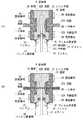
送出部8は、図5(A)及び(B)に示すように、ピストン21、シリンダ部22、蓋部23、24、一方向弁25、26、パッキン27、パッキン固定部28及び固定部材29を含む構成とされる。なお、図5(A)においてピストン21は往復動する際に最も引き戻される位置(以下、これを引戻位置とも呼ぶ)にあり、図5(B)においてピストン21は往復動する際に最も押し込まれる位置(以下、押切位置とも呼ぶ)にある。[2. (Configuration of sending unit)
As shown in FIGS. 5A and 5B, the delivery unit 8 includes a piston 21, a
ピストン21は、先端部21A以外の本体部21Bが例えば直径が1.03mmの円柱形状でなり、先端部21Aが先端に近づくに連れて径が小さくなる円錐台形状に形成される。 The piston 21 is formed in a truncated cone shape in which the main body portion 21B other than the distal end portion 21A has a cylindrical shape with a diameter of, for example, 1.03 mm, and the diameter decreases as the distal end portion 21A approaches the distal end.
ピストン21は、駆動部9により駆動されてシリンダ部22に形成された円柱形状に形成された中空の内部空間22A内で所定のストロークで摺動する。ピストン21の材質としては、例えば、ステンレス鋼、銅合金、アルミ合金、チタン材、ポリプロピレンやポリカーボネートなどの熱可塑性エラストマー等が挙げられる。 The piston 21 is driven by the drive unit 9 and slides with a predetermined stroke in a hollow
シリンダ部22は、一端からピストン21が挿入されて摺動する内部空間22Aが設けられる。またシリンダ部22は、内部空間22Aの他端に接して該内部空間22Aと直交した流路22Bがシリンダ部22の対向する側面間を貫通するようにして設けられる。 The
シリンダ部22は、内部空間22Aにおけるピストン21が挿入される一端に該ピストン21との間で薬液の漏洩を防止するパッキン27及び該パッキン27を固定するパッキン固定部28が設けられる。薬液の漏洩を防止するためのパッキン27には、例えばXリングやOリング等が挙げられ、本実施の形態においてはXリングが適応される。 The
パッキン27は、シリンダ部22における内部空間22Aが設けられた面側からシリンダ部22内に挿入され、パッキン固定部28により押え付けられて固定される。パッキン固定部28は、一部がシリンダ部22内に嵌合され、残りの部分が外部に露出するようにしてパッキン27を固定する。 The packing 27 is inserted into the
シリンダ部22は、流路22Bが形成された側面にそれぞれ蓋部23及び24が固定部材29を介して接続される。蓋部23及び24は、シリンダ部22の流路22Bと対向する位置に、該流路22Bに沿って貫通した流路23A及び24Aが設けられる。 The
蓋部23は、流路23Aの一端がシリンダ部22の流路22Bに接続され、流路23Aの他端が吸込管7Aに接続され、吸込管7Aと流路22Bとを連通させる。 One end of the flow path 23A is connected to the flow path 22B of the
蓋部24は、流路24Aの一端がシリンダ部22の流路22Bに接続され、流路24Aの他端が送出管7Bに接続され、流路22Bと送出管7Bとを連通させる。 In the lid 24, one end of the
送出部8は、蓋部23の流路23Aとシリンダ部22の流路22Bとの間に一方向弁25が設けられ、シリンダ部22の流路22Bと蓋部24の流路24Aとの間に一方向弁26が設けられる。 The delivery section 8 is provided with a one-way valve 25 between the flow path 23A of the
一方向弁25は、蓋部23の流路23Aからシリンダ部22の流路22Bへ流れる薬液を通過させ、シリンダ部22の流路22Bから蓋部23の流路23Aへは薬液を通過させないものであり、例えばアンブレラ弁が適応される。 The one-way valve 25 allows the chemical liquid flowing from the flow path 23A of the
一方向弁26は、シリンダ部22の流路22Bから蓋部24の流路24Aへ流れる薬液を通過させ、シリンダ部22の流路22Bから蓋部24の流路24Aへは薬液を通過させないものであり、例えばアンブレラ弁が適応される。 The one-
送出部8は、薬液貯蔵部6から生体内に薬液を送出する際、ピストン21が押切位置から引戻位置まで内部空間22A内で駆動部9により移動され、薬液貯蔵部6に貯蔵された薬液を内部空間22A内に吸い出す。 The delivery unit 8 moves the piston 21 from the push-off position to the retracted position by the drive unit 9 in the
そして送出部8は、ピストン21が引戻位置から押切位置に駆動部9により移動されことにより、内部空間22Aに吸い出された薬液を生体内へ送出する。 And the delivery part 8 sends out the chemical | medical solution suck | inhaled by 22 A of internal spaces in the living body, when the piston 21 is moved by the drive part 9 from a retracted position to a pushing position.
送出部8は、ピストン21を一往復させる動作で約1〜2μLの薬液を使用者の体内に投与でき、この動作を設定された周期及び間隔で繰り返し行うことにより、所望の投与速度及び投与量で薬液を使用者に投与できる。 The delivery unit 8 can administer about 1 to 2 μL of a chemical solution into the user's body by reciprocating the piston 21 once, and by repeating this operation at a set cycle and interval, a desired administration rate and dosage can be obtained. The drug solution can be administered to the user.
ところで送出部8では、図6に示すように、初期状態(出荷状態)において、ピストン21が引戻位置よりも引かれた位置で、かつ円錐台形状に形成された先端部21Aの一部が周方向に渡ってパッキン27と接触する位置(以下、これを初期位置とも呼ぶ)に配される。 By the way, in the delivery part 8, as shown in FIG. 6, in the initial state (shipment state), a part of the tip part 21A formed in the truncated cone shape is a position where the piston 21 is pulled from the retracted position. It arrange | positions to the position (henceforth an initial position) which contacts the packing 27 over the circumferential direction.
従って送出部8では、ピストン21がテーパ状の先端部21Aでパッキン27と接触しているので、パッキン27のつぶれ量がピストン21の本体部21Bと接触しているときよりも減少させることができる。これにより送出部8では、ピストン21とパッキン27との接触抵抗を減少させることができる。 Therefore, in the delivery part 8, since the piston 21 is in contact with the packing 27 at the tapered tip part 21A, the collapse amount of the packing 27 can be reduced as compared with the case where it is in contact with the main body part 21B of the piston 21. . Thereby, in the delivery part 8, the contact resistance of the piston 21 and the packing 27 can be reduced.
そして送出部8は、薬液投与装置1が起動されると、駆動部9によりピストン21が引戻位置に移動される。 And as for the delivery part 8, when the chemical | medical solution administration apparatus 1 is started, the piston 21 will be moved to a retracted position by the drive part 9. FIG.
〔3.駆動部の構成〕
駆動部9は、図7に示すように、土台部31、モータ32、モータ支持部34、モータ固定板35、固定板支持部36、軸受部37、カップリング38、軸受支持部39を含む構成とされる。[3. (Configuration of drive unit)
As shown in FIG. 7, the drive unit 9 includes a base unit 31, a motor 32, a motor support unit 34, a motor fixing plate 35, a fixed plate support unit 36, a bearing unit 37, a coupling 38, and a bearing support unit 39. It is said.
駆動部9は、土台部31の上に各部が配される。モータ32は、モータ支持部34と固定板支持部36に支持されるモータ固定板35とにより挟持されて土台部31に固定される。 Each part of the drive unit 9 is arranged on the base unit 31. The motor 32 is sandwiched between a motor support portion 34 and a motor fixing plate 35 supported by the fixing plate support portion 36 and fixed to the base portion 31.
モータ32は、モータ固定板35側の側面から突出するモータ軸33が設けられる。モータ軸33の側面にはネジ溝33Aが形成される。 The motor 32 is provided with a motor shaft 33 that protrudes from the side surface on the motor fixing plate 35 side. A screw groove 33 </ b> A is formed on the side surface of the motor shaft 33.
軸受部37は、モータ32の軸方向に沿って細長い略直方体状で内部が中空に形成される。軸受部37は、略直方体状の短辺に相当する側面中央に、モータ32のモータ軸33が貫通して配されてネジ溝33Aと螺合するネジ孔37Aが設けられる。 The bearing portion 37 has a substantially rectangular parallelepiped shape that is elongated along the axial direction of the motor 32 and has a hollow interior. The bearing portion 37 is provided with a screw hole 37A at the center of the side surface corresponding to the short side of the substantially rectangular parallelepiped shape, through which the motor shaft 33 of the motor 32 is inserted and screwed into the screw groove 33A.
軸受部37は、略直方体状の短辺に相当してネジ孔37Aが設けられた側面と対向する側面にカップリング38を介してピストン21がモータ軸33と同軸上に接続される。また、軸受部37は、軸受支持部39に支持される。なお、カップリング38は、例えば、モータ軸33とピストン21との軸方向のずれを緩衝するものが適応される。 In the bearing portion 37, the piston 21 is coaxially connected to the motor shaft 33 via a coupling 38 on a side surface facing a side surface provided with a screw hole 37 </ b> A corresponding to a short side of a substantially rectangular parallelepiped shape. The bearing portion 37 is supported by the bearing support portion 39. As the coupling 38, for example, a coupling that absorbs axial displacement between the motor shaft 33 and the piston 21 is applied.
駆動部9は、図7及び図8に示すように、モータ32が駆動されることによりモータ軸33が回転し、該回転に応じてモータ軸33に螺合された軸受部37が軸方向に移動してピストン21を軸方向に往復動させる。これにより駆動部9は、ピストン21をシリンダ部22の内部空間22A内で摺動させる。なお図7(A)及び(B)においてはピストン21が引戻位置にあり、図8においてはピストン21が押切位置にある。 As shown in FIGS. 7 and 8, the drive unit 9 rotates the motor shaft 33 when the motor 32 is driven, and the bearing unit 37 screwed to the motor shaft 33 in the axial direction is driven in accordance with the rotation. Move and reciprocate the piston 21 in the axial direction. As a result, the drive unit 9 slides the piston 21 in the
このように駆動部9は、モータ32のモータ軸33がピストン21と同軸上に配されているので、モータ軸33が回転することにより軸受部37に加えられる力と、該力によりピストン21に加えられる力とが同一方向となり、ピストン21の推力の損失がなくなる。 Thus, since the motor shaft 33 of the motor 32 is arranged coaxially with the piston 21, the drive unit 9 has a force applied to the bearing portion 37 by the rotation of the motor shaft 33 and the force applied to the piston 21. The applied force is in the same direction, and the thrust loss of the piston 21 is eliminated.
従って駆動部9は、ピストン21をシリンダ部22の内部空間22A内で安定したストローク距離で摺動させることができる。また駆動部9は、ピストン21の推力の損失がなくなることにより、より小さい力でピストン21を駆動することができるので、モータ32やバッテリ等を小さくすることができ、装置全体を小型化することができる。なお、ピストン21の側面には摺動抵抗を減らすためにダイヤモンドライクカーボンがコーティングされていてもよい。 Therefore, the drive unit 9 can slide the piston 21 with a stable stroke distance in the
一方、ピストンとモータの軸部とが同軸上に配されていない装置では、軸部が回転することにより軸受部に加えられる力と、該力によりピストンに加えられる力とがオフセットすることにより、ピストンの推力の損失が増大すると共に、力のオフセットにより軸受部やピストンの摺動抵抗が増加することになり、ピストンのストロークが安定しないだけでなく、装置全体が大型化してしまう。 On the other hand, in a device in which the piston and the shaft portion of the motor are not arranged coaxially, the force applied to the bearing portion by the rotation of the shaft portion and the force applied to the piston by the force are offset, The loss of thrust of the piston increases, and the sliding resistance of the bearing portion and the piston increases due to the offset of the force, which not only stabilizes the stroke of the piston but also increases the size of the entire apparatus.
ところで薬液投与装置1では、パッキン固定部28とカップリング38との間がチューブ状の柔軟性を有するフィルム40で覆われる。フィルム40の材質としては、例えばポリエチレン等が適応される。 By the way, in the chemical solution administration device 1, the space between the
フィルム40は、両端が例えばOリングでなるフィルム固定部41及び42によりパッキン固定部28及びカップリング38に対してそれぞれ周方向にわたって隙間なく固定される。 The
フィルム40は、柔軟性を有しているので、ピストン21が引戻位置にある状態から押切位置にある状態にわたって常にピストン21を覆った状態を維持することができる。 Since the
従って薬液投与装置1では、ピストン21をフィルム40外の空気に触れることなくシリンダ部22の内部空間22A内で摺動させることができる。これにより薬液投与装置1は、内部空間22A内に入り込むピストン21の清潔性をより保持することができる。 Therefore, in the chemical solution administration device 1, the piston 21 can be slid within the
〔4.薬液投与装置の電気的構成〕
薬液投与装置1は、図9に示すように、CPU(Central Processing Unit)51、ROM(Read Only Memory)52、RAM(Random Access Memory)53、電源部54、インターフェース部(I/F部)55、報知部56及び駆動部9がバス57を介して接続される。[4. Electrical configuration of drug solution administration device]
As shown in FIG. 9, the drug solution administration device 1 includes a CPU (Central Processing Unit) 51, a ROM (Read Only Memory) 52, a RAM (Random Access Memory) 53, a
CPU51、ROM52、RAM53、電源部54及び報知部56は、基板部10上に配される。電源部54は電池が適応される。インターフェース部55は、上筐体部3又は下筐体部2に配されユーザの入力命令を受け付けるボタン(図示せず)等が適応される。報知部56はスピーカが適応される。 The
CPU51は、ROM52に格納された基本プログラムをRAM53に読み出して実行することより全体を統括制御すると共に、ROM52に記憶された各種アプリケーションプログラムをRAM53に読み出して実行することにより各種処理を実行する。 The
薬液投与装置1は、薬液を使用者に投与する場合、図10に示すフローチャートに従って薬液投与処理を実行する。 When administering a chemical solution to a user, the chemical solution administration device 1 executes a chemical solution administration process according to the flowchart shown in FIG.
CPU51は、ステップSP1において薬液投与装置1に各種指示を与えるコントローラ(図示せず)から起動信号を受信すると各部を起動し、ステップSP2において駆動部9を駆動させてピストン21を初期位置から引戻位置に移動させる。 When the
ステップSP3において使用者により薬液貯蔵部6に薬液が注入され、ステップSP4において薬液投与装置1が貼付部4を介して使用者の皮膚に貼り付けられた後、穿刺機構5により穿刺針が使用者に穿刺される。 In step SP3, the user injects the drug solution into the drug solution storage unit 6, and in step SP4, the drug solution administration device 1 is affixed to the user's skin via the affixing unit 4, and then the puncture mechanism 5 inserts the puncture needle into the user. Is punctured.
CPU51は、ステップSP5において、コントローラから送信される投与量、投与速度等の投与パラメータを受信すると、該投与パラメータに応じて駆動部9を駆動させるようにパラメータ設定をする。 In step SP5, when the
CPU51は、ステップSP6において駆動部9を駆動させて薬液の投与を開始し、ステップSP7において薬液がすべて投与したと判断した場合には薬液の投与を終了する。 In step SP6, the
一方、CPU51は、ステップSP7において薬液がすべて投与していないと判断した場合にはステップSP8において設定された投与量の薬液を投与したか判断し、投与していないと判断した場合にはステップSP9において薬液の投与を継続する。 On the other hand, if the
CPU51は、ステップSP8において設定された投与量の薬液を投与したと判断した場合にはステップSP10においてコントローラからの指示入力を待ち、指示があった場合にはステップSP5〜SP10を順次行う。 The
〔5.効果等〕
以上の構成によれば、薬液投与装置1は、初期状態(出荷状態)において、ピストン21が引戻位置よりも引かれた位置で、かつ円錐台形状に形成された先端部21Aの一部が周方向に渡ってパッキン27と接触する位置(初期位置)に配され、薬液が薬液貯蔵部6に注入される前にピストン21を引き戻し位置させる。[5. Effect etc.)
According to the above configuration, in the drug solution administration device 1, in the initial state (shipment state), a part of the tip portion 21 </ b> A formed in the truncated cone shape is a position where the piston 21 is pulled from the retracted position. It arrange | positions to the position (initial position) which contacts the packing 27 over the circumferential direction, and before the chemical | medical solution is inject | poured into the chemical | medical solution storage part 6, the piston 21 is pulled back.
これにより薬液投与装置1では、ピストン21が初期位置にあるときにはパッキン27のつぶれ量が減少するので、パッキン27がピストン21の本体部21Bと接触しているときよりも接触抵抗を減少させることができる。 Thereby, in the chemical solution administration device 1, the collapse amount of the packing 27 is reduced when the piston 21 is in the initial position, so that the contact resistance can be reduced more than when the packing 27 is in contact with the main body portion 21 </ b> B of the piston 21. it can.
従って薬液投与装置1は、ピストン21とパッキン27との接触抵抗(始動抵抗)を減少させることができるので、ピストン21とパッキン27とが時間経過とともに始動抵抗が大きくなったとしても、その値を従来と比して格段に減少させることができる。 Therefore, since the chemical solution administration device 1 can reduce the contact resistance (starting resistance) between the piston 21 and the packing 27, even if the starting resistance of the piston 21 and the packing 27 increases with the passage of time, the value is set. Compared to the conventional case, it can be significantly reduced.
かくして薬液投与装置1は、使用開始時に始動抵抗を受けてピストンを始動させるために大きな力が必要なく、装置全体の大きさを小型化することができる。 Thus, the medicinal-solution administration device 1 does not require a large force to start the piston upon receiving a starting resistance at the start of use, and can reduce the size of the entire device.
また薬液投与装置1では、ピストン21が円錐台形状に形成されているので初期位置から引戻位置に移動する際にその作動をより確実に行うことができる。 Further, in the drug solution administration device 1, since the piston 21 is formed in a truncated cone shape, the operation can be performed more reliably when moving from the initial position to the retracted position.
〔6.他の実施の形態〕
上述した実施の形態においては、ピストン21の先端部21Aが円錐台形状に形成されているようにした場合について述べたが、本発明はこれに限らず、ピストンの先端が本体部と同様に円柱状に形成されていてもよい。[6. Other Embodiments]
In the above-described embodiment, the case where the tip 21A of the piston 21 is formed in the shape of a truncated cone has been described. However, the present invention is not limited to this, and the tip of the piston is circular like the main body. It may be formed in a column shape.
例えば図11に示すように、ピストン121は、先端部121A及び本体部121Bが同一径の円柱形上をしており、初期状態において、引戻位置よりも引かれた位置で、かつパッキン27における摺動方向に沿った一部と接触する初期位置にある。これにより初期状態において、ピストン121とパッキン27との接触抵抗(始動抵抗)を減少させることができる。 For example, as shown in FIG. 11, the piston 121 has a tip 121A and a main body 121B on a columnar shape having the same diameter, and in an initial state, the piston 121 is at a position pulled from the retracted position and in the packing 27. It is in the initial position which contacts a part along a sliding direction. Thereby, in the initial state, the contact resistance (starting resistance) between the piston 121 and the packing 27 can be reduced.
本発明は、例えば医療分野に適用することができる。 The present invention can be applied to the medical field, for example.
1……薬液投与装置、2……下筐体部、3……上筐体部、4……貼付部、5……穿刺機構、6……薬液貯蔵部、7……流路部、8……送出部、9……駆動部、10……基板部、11……外筒、11D……突出部、11F……突起部、12……ピストン、12A……溝部、13……薬液貯蔵空間、21……ピストン、22……シリンダ部、22A……内部空間、22B……流路、22C……対向面、23、24……蓋部、25、26……一方向弁、27……パッキン、28……パッキン固定部、31……土台部、32……モータ、33……モータ軸、37……軸受部、38……カップリング、40……フィルム、51……CPU、52……ROM、53……RAM、54……電源部、55……インターフェース部、56……報知部、57……バス DESCRIPTION OF SYMBOLS 1 ... Chemical solution administration apparatus, 2 ... Lower housing | casing part, 3 ... Upper housing | casing part, 4 ... Pasting part, 5 ... Puncture mechanism, 6 ... Chemical liquid storage part, 7 ... Channel part, 8 ...... Sending part, 9 ... Drive part, 10 ... Substrate part, 11 ... Outer cylinder, 11D ... Protruding part, 11F ... Protruding part, 12 ... Piston, 12A ... Groove part, 13 ... Chemical solution storage Space, 21 ... Piston, 22 ... Cylinder part, 22A ... Internal space, 22B ... Flow path, 22C ... Opposing surface, 23, 24 ... Lid part, 25, 26 ... One-way valve, 27 ... ... packing, 28 ... packing fixing part, 31 ... base part, 32 ... motor, 33 ... motor shaft, 37 ... bearing part, 38 ... coupling, 40 ... film, 51 ... CPU, 52 ... ROM, 53 ... RAM, 54 ... power supply, 55 ... interface, 56 ... notification, 57 ... bar
Claims (4)
Translated fromJapanese薬液が貯蔵される薬液貯蔵部と、
前記薬液貯蔵部から生体内へ薬液が流れる流路を形成する流路部と、
ピストンと、
一端が前記流路部と接続され、他端側から前記ピストンが挿入されて摺動する内部空間を形成するシリンダ部と、
前記ピストンを前記シリンダ部の内部空間内で、最も押し切られた押切位置から最も引き戻された引戻位置までの間で摺動させる駆動部と、
前記シリンダ部の内部空間における前記ピストンが引戻位置にあるときに該ピストンの先端より他端側に配され、前記ピストンと周方向にわたって接し、前記ピストンと前記シリンダ部との間から外部に薬液が漏れることを防止するパッキンとを有し、
前記ピストンは、初期状態において、前記引戻位置よりもさらに引かれた位置であって、かつ前記ピストンと前記パッキンとの間の接触抵抗が前記ピストンが前記引戻位置にあるときより小さくなる初期位置に配される
薬液投与装置。A chemical liquid administration device used by being attached to the skin of a living body,
A chemical solution storage unit for storing the chemical solution;
A flow path section that forms a flow path for the chemical liquid to flow from the chemical liquid storage section into the living body;
A piston,
One end is connected to the flow path portion, and a cylinder portion that forms an internal space in which the piston is inserted and slid from the other end side;
A drive unit that slides the piston in the internal space of the cylinder unit from the most pressed position to the most retracted position;
When the piston in the internal space of the cylinder portion is in the retracted position, the piston is disposed on the other end side from the tip of the piston, is in contact with the piston over the circumferential direction, and is exposed to a chemical solution from between the piston and the cylinder portion to the outside. Has a packing to prevent leakage,
In an initial state, the piston is in a position further pulled than the retracted position, and an initial contact resistance between the piston and the packing is smaller than when the piston is in the retracted position. A chemical dosing device placed at the location.
請求項1に記載の薬液投与装置。The drug solution administration device according to claim 1, further comprising a control unit that controls the drive unit to move the piston from the initial position to the retracted position before the drug solution is injected from the outside into the drug solution storage unit. .
先端部がテーパ状に形成され、初期状態において、該テーパ状に形成された先端部が前記パッキンと接する
請求項1に記載の薬液投与装置。The piston is
The medicinal-solution administration device according to claim 1, wherein the tip is formed in a tapered shape, and the tapered tip is in contact with the packing in an initial state.
円柱形状に形成され、初期状態において、先端部が前記パッキンの一部と接する
請求項1に記載の薬液投与装置。The piston is
The medicinal-solution administration device according to claim 1, wherein the drug solution administration device is formed in a cylindrical shape, and a tip portion is in contact with a part of the packing in an initial state.
Applications Claiming Priority (3)
| Application Number | Priority Date | Filing Date | Title |
|---|---|---|---|
| JP2012212603 | 2012-09-26 | ||
| JP2012212603 | 2012-09-26 | ||
| PCT/JP2013/005609WO2014050065A1 (en) | 2012-09-26 | 2013-09-24 | Medical fluid administration device |
Publications (2)
| Publication Number | Publication Date |
|---|---|
| JPWO2014050065A1 JPWO2014050065A1 (en) | 2016-08-22 |
| JP5986637B2true JP5986637B2 (en) | 2016-09-06 |
Family
ID=50387504
Family Applications (1)
| Application Number | Title | Priority Date | Filing Date |
|---|---|---|---|
| JP2014538167AActiveJP5986637B2 (en) | 2012-09-26 | 2013-09-24 | Chemical solution administration device |
Country Status (5)
| Country | Link |
|---|---|
| US (1) | US9943642B2 (en) |
| EP (1) | EP2902052B1 (en) |
| JP (1) | JP5986637B2 (en) |
| CN (1) | CN104640585B (en) |
| WO (1) | WO2014050065A1 (en) |
Families Citing this family (9)
| Publication number | Priority date | Publication date | Assignee | Title |
|---|---|---|---|---|
| CN105771037B (en)* | 2015-12-31 | 2019-03-01 | 深圳麦科田生物医疗技术有限公司 | A kind of syringe pump |
| EP3517094A4 (en)* | 2016-09-26 | 2020-08-12 | Terumo Kabushiki Kaisha | Liquid medicine filling device and liquid medicine filling method |
| ES2985905T3 (en) | 2016-11-22 | 2024-11-07 | Lts Device Tech Ltd | Apparatus for delivering a therapeutic substance |
| WO2018181657A1 (en)* | 2017-03-30 | 2018-10-04 | テルモ株式会社 | Liquid medicine administration device and operation method thereof |
| DE102017111299A1 (en)* | 2017-05-23 | 2018-11-29 | B. Braun Melsungen Ag | Infusion pump with a different operating conditions ingestible pump module |
| ES2986346T3 (en) | 2018-10-05 | 2024-11-11 | Lts Device Tech Ltd | Activation sequence |
| US12318576B2 (en) | 2019-03-05 | 2025-06-03 | Eitan Medical Ltd. | Infusion pump with toggling capability |
| EP3934714A1 (en) | 2019-03-05 | 2022-01-12 | Eitan Medical Ltd. | Infusion pump with valve compensation |
| TW202527982A (en) | 2023-09-11 | 2025-07-16 | 美商默門塔醫藥公司 | Pharmaceutical compositions of fcrn antibodies |
Family Cites Families (7)
| Publication number | Priority date | Publication date | Assignee | Title |
|---|---|---|---|---|
| US5876189A (en)* | 1997-12-09 | 1999-03-02 | Lube Devices, Inc. | Pumped fluid metering device for the precise feeding of a fluid |
| US9259175B2 (en)* | 2006-10-23 | 2016-02-16 | Abbott Diabetes Care, Inc. | Flexible patch for fluid delivery and monitoring body analytes |
| US7905868B2 (en)* | 2006-08-23 | 2011-03-15 | Medtronic Minimed, Inc. | Infusion medium delivery device and method with drive device for driving plunger in reservoir |
| US20080097291A1 (en)* | 2006-08-23 | 2008-04-24 | Hanson Ian B | Infusion pumps and methods and delivery devices and methods with same |
| JP5326265B2 (en)* | 2007-09-26 | 2013-10-30 | Nok株式会社 | Sealing device |
| CN201492768U (en)* | 2009-08-07 | 2010-06-02 | 无锡顶点医疗器械有限公司 | Insulin pump infusion device |
| CN103826678A (en)* | 2011-09-26 | 2014-05-28 | 泰尔茂株式会社 | Liquid-drug administration device, puncturing device, liquid-drug filling device, liquid-drug filling method, and liquid-drug filling system |
- 2013
- 2013-09-24JPJP2014538167Apatent/JP5986637B2/enactiveActive
- 2013-09-24EPEP13842945.1Apatent/EP2902052B1/enactiveActive
- 2013-09-24WOPCT/JP2013/005609patent/WO2014050065A1/enactiveApplication Filing
- 2013-09-24CNCN201380047786.6Apatent/CN104640585B/enactiveActive
- 2015
- 2015-03-24USUS14/667,469patent/US9943642B2/enactiveActive
Also Published As
| Publication number | Publication date |
|---|---|
| JPWO2014050065A1 (en) | 2016-08-22 |
| US20150258274A1 (en) | 2015-09-17 |
| CN104640585B (en) | 2017-05-03 |
| EP2902052A1 (en) | 2015-08-05 |
| EP2902052A4 (en) | 2016-05-18 |
| CN104640585A (en) | 2015-05-20 |
| US9943642B2 (en) | 2018-04-17 |
| EP2902052B1 (en) | 2017-08-16 |
| WO2014050065A1 (en) | 2014-04-03 |
Similar Documents
| Publication | Publication Date | Title |
|---|---|---|
| JP5986637B2 (en) | Chemical solution administration device | |
| CN112566680B (en) | Movable infusion pump and components for use therewith | |
| JP7094295B2 (en) | Automatic fluid injection device | |
| US20090259176A1 (en) | Transdermal patch system | |
| JP6051204B2 (en) | Puncture device and drug solution administration device | |
| US11752259B2 (en) | Liquid medication injection device | |
| EP2298396A1 (en) | Hub assembly having a hidden needle for a drug delivery pen | |
| KR20210040712A (en) | Apparatus for Infusing medical liquid | |
| CN103957968B (en) | Arrangements for sequential delivery of fluid volumes | |
| JP2020517393A (en) | Automatic fluid injection device | |
| US12239816B2 (en) | Drug delivery device cassette | |
| CN119215261A (en) | Fluid conveying device and fluid conveying system | |
| AU2022212037A9 (en) | Hard seal compact, positive displacement pump with reciprocating motion | |
| JP2013192853A (en) | Liquid medicine administration apparatus | |
| JP6360036B2 (en) | Medicine bottle dosing system and method | |
| JP2013192851A (en) | Medicine solution administration apparatus | |
| US20130324927A1 (en) | Syringe assembly for a medication pump or the like | |
| JP2013192852A (en) | Liquid medicine administration apparatus | |
| JP7394108B2 (en) | fluid injection equipment | |
| JP2012200418A (en) | Liquid chemical dosing apparatus | |
| JP2013070790A (en) | Drug solution delivery device | |
| JP2012200417A (en) | Liquid medicine administration apparatus | |
| JP2012062762A (en) | Disposable liquid supply pump | |
| JP2014064780A (en) | Liquid medicine administration device | |
| JP2012200416A (en) | Liquid medicine administration apparatus |
Legal Events
| Date | Code | Title | Description |
|---|---|---|---|
| TRDD | Decision of grant or rejection written | ||
| A01 | Written decision to grant a patent or to grant a registration (utility model) | Free format text:JAPANESE INTERMEDIATE CODE: A01 Effective date:20160712 | |
| A61 | First payment of annual fees (during grant procedure) | Free format text:JAPANESE INTERMEDIATE CODE: A61 Effective date:20160805 | |
| R150 | Certificate of patent or registration of utility model | Ref document number:5986637 Country of ref document:JP Free format text:JAPANESE INTERMEDIATE CODE: R150 | |
| R250 | Receipt of annual fees | Free format text:JAPANESE INTERMEDIATE CODE: R250 | |
| R250 | Receipt of annual fees | Free format text:JAPANESE INTERMEDIATE CODE: R250 | |
| R250 | Receipt of annual fees | Free format text:JAPANESE INTERMEDIATE CODE: R250 | |
| R250 | Receipt of annual fees | Free format text:JAPANESE INTERMEDIATE CODE: R250 | |
| R250 | Receipt of annual fees | Free format text:JAPANESE INTERMEDIATE CODE: R250 | |
| R250 | Receipt of annual fees | Free format text:JAPANESE INTERMEDIATE CODE: R250 |