JP5978520B2 - Heat insulation box - Google Patents
Heat insulation boxDownload PDFInfo
- Publication number
- JP5978520B2 JP5978520B2JP2011266794AJP2011266794AJP5978520B2JP 5978520 B2JP5978520 B2JP 5978520B2JP 2011266794 AJP2011266794 AJP 2011266794AJP 2011266794 AJP2011266794 AJP 2011266794AJP 5978520 B2JP5978520 B2JP 5978520B2
- Authority
- JP
- Japan
- Prior art keywords
- reinforcing member
- door
- door frame
- frame
- side reinforcing
- Prior art date
- Legal status (The legal status is an assumption and is not a legal conclusion. Google has not performed a legal analysis and makes no representation as to the accuracy of the status listed.)
- Active
Links
- 238000009413insulationMethods0.000titleclaimsdescription40
- 230000003014reinforcing effectEffects0.000claimsdescription114
- 238000003860storageMethods0.000claimsdescription16
- 239000000853adhesiveSubstances0.000claimsdescription12
- 230000001070adhesive effectEffects0.000claimsdescription12
- 239000012943hotmeltSubstances0.000description30
- 230000002093peripheral effectEffects0.000description17
- 230000002787reinforcementEffects0.000description10
- 235000013311vegetablesNutrition0.000description9
- 238000005192partitionMethods0.000description8
- 238000004519manufacturing processMethods0.000description6
- 239000000463materialSubstances0.000description5
- 238000000034methodMethods0.000description5
- 239000007921spraySubstances0.000description5
- 229910052751metalInorganic materials0.000description4
- 239000002184metalSubstances0.000description4
- 229910001220stainless steelInorganic materials0.000description4
- 239000010935stainless steelSubstances0.000description4
- 229920003002synthetic resinPolymers0.000description4
- 239000000057synthetic resinSubstances0.000description4
- 229910052782aluminiumInorganic materials0.000description3
- XAGFODPZIPBFFR-UHFFFAOYSA-NaluminiumChemical compound[Al]XAGFODPZIPBFFR-UHFFFAOYSA-N0.000description3
- 238000010586diagramMethods0.000description3
- 230000000694effectsEffects0.000description3
- 239000012212insulatorSubstances0.000description3
- 238000005057refrigerationMethods0.000description3
- VYPSYNLAJGMNEJ-UHFFFAOYSA-NSilicium dioxideChemical compoundO=[Si]=OVYPSYNLAJGMNEJ-UHFFFAOYSA-N0.000description2
- 229920000122acrylonitrile butadiene styrenePolymers0.000description2
- 230000004888barrier functionEffects0.000description2
- 238000005452bendingMethods0.000description2
- 239000007769metal materialSubstances0.000description2
- 238000000465mouldingMethods0.000description2
- 229920005989resinPolymers0.000description2
- 239000011347resinSubstances0.000description2
- JOYRKODLDBILNP-UHFFFAOYSA-NEthyl urethaneChemical compoundCCOC(N)=OJOYRKODLDBILNP-UHFFFAOYSA-N0.000description1
- 238000006243chemical reactionMethods0.000description1
- 239000011162core materialSubstances0.000description1
- 125000004122cyclic groupChemical group0.000description1
- 229920006248expandable polystyrenePolymers0.000description1
- 230000008014freezingEffects0.000description1
- 238000007710freezingMethods0.000description1
- 239000011491glass woolSubstances0.000description1
- 239000012784inorganic fiberSubstances0.000description1
- 239000002648laminated materialSubstances0.000description1
- 230000007774longtermEffects0.000description1
- 239000003595mistSubstances0.000description1
- 238000012986modificationMethods0.000description1
- 230000004048modificationEffects0.000description1
- 230000000149penetrating effectEffects0.000description1
- 229920000098polyolefinPolymers0.000description1
- 229920002635polyurethanePolymers0.000description1
- 239000004814polyurethaneSubstances0.000description1
- 239000004800polyvinyl chlorideSubstances0.000description1
- 229920000915polyvinyl chloridePolymers0.000description1
- 238000005096rolling processMethods0.000description1
- 239000000377silicon dioxideSubstances0.000description1
- 229920005992thermoplastic resinPolymers0.000description1
- 230000009466transformationEffects0.000description1
- 238000003466weldingMethods0.000description1
Images


Classifications
- F—MECHANICAL ENGINEERING; LIGHTING; HEATING; WEAPONS; BLASTING
- F25—REFRIGERATION OR COOLING; COMBINED HEATING AND REFRIGERATION SYSTEMS; HEAT PUMP SYSTEMS; MANUFACTURE OR STORAGE OF ICE; LIQUEFACTION SOLIDIFICATION OF GASES
- F25D—REFRIGERATORS; COLD ROOMS; ICE-BOXES; COOLING OR FREEZING APPARATUS NOT OTHERWISE PROVIDED FOR
- F25D2201/00—Insulation
- F25D2201/10—Insulation with respect to heat
- F25D2201/14—Insulation with respect to heat using subatmospheric pressure
Landscapes
- Thermal Insulation (AREA)
- Refrigerator Housings (AREA)
Description
Translated fromJapanese本発明の実施形態は、断熱箱に関する。 Embodiments of the present invention relate to a heat insulation box.
従来、例えば冷蔵庫などに用いられる断熱箱において、その扉の内部に補強用の補強部材を設けた構成が開示されている。通常、このような補強部材は、ネジなどによって扉の内部に固定される。
しかし、補強部材をネジなどで貫いて固定する場合、専用の工具を用いて複数箇所についてネジ締めを行う必要がある。そのため、補強部材の取付け工数が増加し、ひいては断熱箱の製造コストの増加に繋がる。また、断熱性能を向上させるために、例えば断熱部材として真空断熱パネルを採用する場合、補強部材を固定するネジが真空断熱パネルに接触して、真空断熱パネルが破損するおそれがあった。Conventionally, in a heat insulating box used for a refrigerator, for example, a configuration in which a reinforcing member for reinforcement is provided inside the door is disclosed. Usually, such a reinforcing member is fixed inside the door with a screw or the like.
However, when fixing the reinforcing member with screws or the like, it is necessary to perform screw tightening at a plurality of locations using a dedicated tool. For this reason, the number of steps for attaching the reinforcing member increases, which leads to an increase in the manufacturing cost of the heat insulation box. Moreover, in order to improve the heat insulation performance, for example, when a vacuum heat insulation panel is adopted as a heat insulation member, there is a possibility that a screw for fixing the reinforcing member contacts the vacuum heat insulation panel and the vacuum heat insulation panel is damaged.
そこで、扉の内部に設けられる補強部材の取付けを容易にして取付け工数の低減を図り、ひいてはコスト低減を図るとともに、真空断熱パネルを扉の内部に安全に設けることができる断熱箱を提供する。 Therefore, it is possible to provide a heat insulating box that can easily mount a reinforcing member provided inside the door to reduce the number of mounting steps, thereby reducing the cost, and can safely provide a vacuum heat insulating panel inside the door.
本実施形態の断熱箱は、貯蔵室およびこの貯蔵室に繋がる開口を有する箱本体と、前記開口を開閉する扉と、を備える。前記扉は、内部に空間が形成された扉枠体と、前記扉枠体の内部の空間に設けられた真空断熱パネルと、前記扉枠体の内部の空間にあって前記扉枠体の側面に接して設けられ他の部材によって貫かれることなく接着剤によって前記扉枠体に接着固定された補強部材と、を有している。The heat insulation box of this embodiment is provided with the box main body which has a storage room and the opening connected to this storage room, and the door which opens and closes the said opening. The door includes a door frame having a space formed therein, a vacuum heat insulation panel provided in the space inside the door frame, and a side surface of the door frame in the space inside the door frame.and have a, and a reinforcing member thatis adhered and fixed to the door frame by an adhesive without being penetrated by the other member is provided in contact with.
以下、複数の実施形態による冷蔵庫を、図面を参照して説明する。なお、各実施形態において実質的に同一の構成部位には同一の符号を付し、説明を省略する。 Hereinafter, refrigerators according to a plurality of embodiments will be described with reference to the drawings. In addition, in each embodiment, the same code | symbol is attached | subjected to the substantially same component, and description is abbreviate | omitted.
(第一実施形態)
まず、第一実施形態について、図1から図4を参照して説明する。
図1に示す断熱箱10は、冷蔵庫の筺体を構成するものである。この断熱箱10には、図示しない圧縮機、凝縮器、冷却器などから構成される冷凍サイクルが組込まれ、これにより冷蔵庫が構成される。この断熱箱10は、主に、箱本体11、および複数の扉、この場合、左右の冷蔵室扉12、13と野菜室扉14と製氷室扉15と小冷凍室扉16と冷凍室扉17とを有して構成されている。そして、断熱箱10は、その内部に貯蔵室として、冷蔵室18、野菜室19、製氷室20、小冷凍室21、および冷凍室22が形成されている。なお、以下の説明においては、箱本体11に対して各扉12〜17側を断熱箱10の前側と定義する。(First embodiment)
First, a first embodiment will be described with reference to FIGS.
The
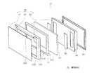
箱本体11は、図2に示すように、分割された複数の断熱壁、この場合、左壁23と右壁24と底壁25と天井壁26と背壁27とを組み合せることによって、前面が開口した箱状に形成されている。また、天井壁26は、その後側が前側に比べて一段低くなる形状に形成されており、この天井壁26の一段低くなった部分と、左壁23および右壁24とで囲まれた部分に機械室28が形成されている。そして、この機械室28には、図示しない冷凍サイクルの圧縮機などが収容される。ちなみに、本実施形態の場合、詳細は図示しないが、各壁23〜27は、外板および内板の間に断熱部材としての真空断熱パネルを挟んで構成されている。 As shown in FIG. 2, the
また、箱本体11には、図2に示すように、前面の開口付近に複数の仕切り部材29が設けられており、さらにこの仕切り部材29の後側には図示しない仕切り壁が設けられる。箱本体11の内部の空間は、この仕切り部材29および図示しない仕切壁によって、複数の貯蔵室18〜22に区分される。 As shown in FIG. 2, the
複数の扉12〜17は、箱本体11の開口側つまり前面側に設けられ、それぞれ貯蔵室18〜22に繋がる開口を開閉する。具体的には、図1に示すように、冷蔵室扉12、13は、観音開き式に構成されて、冷蔵室18の前側に設けられている。この場合、冷蔵室扉12、13は、それぞれ左右のヒンジ121、131を回転軸として左右方向へ回転し、冷蔵室18の前面の開口を開閉する。 The plurality of
野菜室扉14は、引出し式に構成されて、野菜室19の前側に設けられている。野菜室19は、その裏側に図示しない野菜収納容器が取付けられ、野菜室19の前側の開口を開閉する。同様に、製氷室扉15は、引出し式に構成されて、製氷室20の前側に設けられている。製氷室扉15は、その裏側に図示しない製氷容器が取付けられ、製氷室20の前側の開口を開閉する。さらに、小冷凍室扉16および冷凍室扉17は、それぞれ小冷凍室21および冷凍室22の前側に設けられている。これら小冷凍室扉16および冷凍室扉17は、その裏側に図示しない収納容器が取付けられ、それぞれ小冷凍室21および冷凍室22の前側の開口を開閉する。 The
次に、扉12〜17の構成について説明する。なお、扉12〜17は、対応する貯蔵室18〜22によって全体の形状はそれぞれ異なるが、何れもほぼ同じ構成であるため、ここでは冷凍室扉17を代表して説明する。
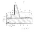
冷凍室扉17は、図3に示すように、扉枠体30を主体として構成されている。この扉枠体30は、扉外部材31、扉内部材32、および扉枠部材33から構成され、その内部に空間が形成される。そして、冷凍室扉17は、図4にも示すように、この扉枠体30の内部の空間に、真空断熱パネル34、枠側補強部材35、突出部側補強部材36、断熱体37、および閉塞板38を有し、さらに扉枠体30の外側にガスケット39などを有して構成されている。Next, the structure of the doors 12-17 is demonstrated. Although the
As shown in FIG. 3, the
具体的には、扉外部材31は、例えばステンレス鋼などの金属製の板によって、図2に示す冷凍室22の前面の開口を覆う大きさの矩形の平坦な板状に形成されている。また、扉内部材32は、例えばABS樹脂などの合成樹脂の材料を真空成形して構成されており、全体として扉外部材31とほぼ同じ大きさの矩形の板状に構成されている。そして、本実施形態の場合、扉内部材32は、図4に示すように、突出部40およびガスケット取付け部41を一体に有して構成されている。 Specifically, the door
突出部40は、図4に示すように、扉内部材32の平坦部分から扉外部材31とは反対側すなわち冷凍室22側へ突出している。そして、この突出部40は、図3に示すように、全体として扉内部材32の外周に沿った矩形の環状に形成されている。この場合、突出部40は、冷凍室22の前面の開口を形成する左壁23、右壁24、底壁25、および仕切り部材29の厚み寸法よりもやや大きい寸法分、扉内部材32の外縁部から内側に位置して設けられている。また、突出部40は、扉内部材32の平坦部分との接続部分において扉外部材31側に向かって開口し、その内側に空間が形成されている。この突出部40の内側の空間は、小収容部42を構成している。そして、この突出部40は、冷凍室扉17を閉じた状態においては、冷凍室22の開口の内側に入り込んでいる。 As shown in FIG. 4, the
ガスケット取付け部41は、突出部40の外側に位置し、突出部40と同様に、全体として扉内部材32の外周に沿った矩形の環状であって、扉外部材31とは反対側つまり冷凍室22側へ向かって開口した溝形状に形成されている。このガスケット取付け部41には、図3に示す溝形状部分にガスケット39が取付けられる。ガスケット39は、例えばポリ塩化ビニルなどの軟質樹脂で全体として矩形の環状に形成されている。そして、詳細は図示しないが、ガスケット39は、その内部に空気層および磁石を有している。そして、ガスケット39は、冷凍室扉17を閉めると、ガスケット39に設けられた磁石が各壁23、24、25および仕切り部材29の前面部分に吸着する。これにより、ガスケット39は、冷凍室22内を気密に保ち、冷凍室22の内外への空気流通を遮断して熱漏洩および熱流入を抑制している。 The
扉枠部材33は、例えばABS樹脂などの合成樹脂の材料を真空成形して構成され、全体として扉外部材31および扉内部材32とほぼ同じ大きさの矩形の枠状に形成されている。すなわち、この扉枠部材33は、図3に示すように、扉内部材32側が開口した浅い箱状であって、その箱状の底面部分つまり扉外部材31側が、扉外部材31よりもやや小さな矩形状に貫かれた形状に構成されている。この扉枠部材33は、主に、周囲部331、底部332、および取手部333から構成されている。周囲部331は、扉外部材31および扉内部材32の面に対してほぼ直角方向に配置されて扉枠部材33の箱状の周囲を構成している。底部332は、扉枠部材33の箱状の底面部分を構成している。そして、取手部333は、周囲部331の上縁部分から前方へ突出して設けられている。なお、取手部333は、扉枠部材33とは別体に構成してもよい。 The
この扉枠部材33は、前側に扉外部材31が取付けられ、後側に扉内部材32が取付けられて、扉外部材31と扉内部材32との間を繋いでいる。このように、扉枠体30は、扉外部材31と扉内部材32と扉枠部材33とが組合わされて構成されている。そして、この扉枠体30の内部には、図4に示すように、扉外部材31と扉内部材32と扉枠部材33とで囲まれた空間が形成されている。この扉外部材31と扉内部材32と扉枠部材33とで囲まれた空間は、大収容部43を構成している。そして、扉枠体30の内部の空間は、小収容部42と大収容部43とによって構成されている。 The
大収容部43には、真空断熱パネル34および枠側補強部材35などが設けられている。真空断熱パネル34は、詳細は図示しないが、例えばグラスウールなどの無機繊維の積層材を圧縮硬化させた芯材を、ガスバリア性能を得るために金属層やシリカなどガスバリア性を有する材料を含んで構成された袋体に収納し、その内部を真空排気して減圧密封させて構成されたものである。なお、各壁23〜27に設けられる真空断熱パネルも、真空断熱パネル34と同様に構成されている。 The large
枠側補強部材35は、図3に示すように、全体として棒状に構成され、扉枠体30の周囲に沿って設けられている。そして、本実施形態の場合、扉枠体30の周囲の四辺に沿って、四個の枠側補強部材35が設けられている。具体的には、この枠側補強部材35は、例えばステンレス鋼やアルミなどの金属材料で構成され、圧延加工や曲げ加工などによって、断面がコ字状に近い溝形に形成されている。すなわち、この枠側補強部材35は、扉枠部材33の周囲部331の内側面に平行な主体部351と、この主体部351に対して幅方向の両側が直角方向へ折り曲げられた曲げ部352とから構成されている。 As shown in FIG. 3, the frame-
この枠側補強部材35は、扉枠体30の側面の一部、この場合、周囲部331の内側面に接して設けられている。すなわち、枠側補強部材35は、主体部351の外側面が周囲部331の内側面に接して設けられている。また、一方の曲げ部352の外側面が底部332の内側面に接し、他方の曲げ部352の外側面がガスケット取付け部41の裏側面に接して設けられている。この場合、四個の枠側補強部材35は、それぞれ真空断熱パネル34の外周の外側に位置し、断面コ形状の開口部分が真空断熱パネル34側つまり扉枠体30の中央へ向いて配置されている。 The frame
また、突出部側補強部材36および断熱体37は、突出部40の内部すなわち小収容部42内に設けられている。突出部側補強部材36は、例えばステンレス鋼やアルミなどの金属製の板から構成されている。そして、この突出部側補強部材36は、扉枠体30の側面の一部、この場合、突出部40の内側面のうちガスケット取付け部41に近い方の面に接して設けられている。 Further, the protruding portion
また、断熱体37は、突出部側補強部材36の周囲を覆い、さらに突出部40の内側の空間すなわち小収容部42を埋めるようにして設けられている。この断熱体37は、断熱性能を有する材料、例えば発泡スチロールや発泡ウレタンなどで構成されている。そして、閉塞板38は、例えば合成樹脂製の板で構成され、突出部40の扉外部材31側の開口部分に設けられている。これにより、閉塞板38は、突出部40の開口部分を閉塞し、小収容部42と大収容部43とを仕切っている。 Further, the
これら枠側補強部材35および突出部側補強部材36は、他の部材、例えばネジなどによって貫かれることなく扉枠体30に固定された、いわゆるネジレスに構成されている。具体的には、枠側補強部材35および突出部側補強部材36は、それぞれ反応性ホットメルトによって、扉枠体30に接着固定されている。反応性ホットメルトは、例えばポリウレタンやポリオレフィンなどの熱可塑性樹脂を主成分とした接着剤である。そして、この反応性ホットメルトは、加熱溶融した状態で接着対象物に塗布され、接着対象物の圧着によって冷却固化した後、空気中や接着対象物の中に含まれる水分と化学反応して固化する。このため、従来のホットメルトでは得られなかった高い耐熱性、強い接着強度、優れた耐久性を得ることができる。 The frame
この場合、枠側補強部材35は、その外側面に反応性ホットメルト44が塗布されている。これにより枠側補強部材35は、扉枠体30の扉内部材32および扉枠部材33に接着固定されている。また、突出部側補強部材36は、ガスケット取付け部41側の面に反応性ホットメルト45が塗布されている。これにより、突出部側補強部材36は、扉枠体30の突出部40の内部であってガスケット取付け部41側の面に接着固定されている。 In this case, the reactive
そして、真空断熱パネル34も、反応性ホットメルトによって扉枠体30に固定されている。つまり、真空断熱パネル34の前後の両面には、反応性ホットメルト44が塗布されている。これにより、真空断熱パネル34は、一方の面すなわち前側の面が扉外部材31に接着固定され、他方の面すなわち後側の面が扉内部材32および閉塞板38に接着固定されている。この場合、真空断熱パネル34を固定する反応性ホットメルト44は、枠側補強部材35を接着固定する反応性ホットメルト44と同じ工程において塗布される。 The vacuum
また、本実施形態の場合、反応性ホットメルト44、45は、例えばスパイラルスプレー方式などによって塗布される。このスパイラルスプレー方式とは、接着剤この場合溶融した反応性ホットメルトに空気圧等を印加し霧状にして塗布するスプレー方式の一種である。このスパイラルスプレー方式において反応性ホットメルトは、霧状にされて螺旋状に塗布される。このスパイラルスプレー方式によれば、被接着面に対してムラ無く均一に反応性ホットメルトを塗布することができる。そのため、接着強度のムラが低減され、長期耐久性に優れたものとすることができる。 In the case of this embodiment, the reactive
ちなみに、本実施形態の場合、扉外部材31と扉枠部材33、および扉内部材32と扉枠部材33とは、それぞれ反応性ホットメルトによって固定されている。しかし、これに限られず、ネジなどを用いて固定してもよい。この場合、ネジの先端や頭などを大収容部43内に露出させずに、真空断熱パネル34に接触させないことが好ましい。 Incidentally, in the case of this embodiment, the door
この構成によれば、大収容部43に設けられた枠側補強部材35および小収容部42に設けられた突出部側補強部材36は、反応性ホットメルト44、45によって接着固定されている。すなわち、枠側補強部材35および突出部側補強部材36は、例えばネジなど他の部材によって貫かれることなく固定された、いわゆるネジレスに構成されている。 According to this configuration, the frame
これによれば、枠側補強部材35および突出部側補強部材36を固定するために、専用の工具を用いて複数箇所のネジ締めなどを行う必要がない。したがって、枠側補強部材35および突出部側補強部材36の取付け工数が低減され、ひいては断熱箱10の製造コストの低減を図ることができる。また、この枠側補強部材35はいわゆるネジレスで固定されている。そのため、扉枠体30の内部に真空断熱パネル34を設けるとともに、その真空断熱パネル34の周囲に枠側補強部材35を設ける場合であっても、枠側補強部材35を固定するネジなどが真空断熱パネル34と干渉することがない。したがって、真空断熱パネル34は、枠側補強部材35を固定するネジなどが接触して破損するおそれがなくなり、これにより、真空断熱パネル34を扉枠体30の内部に安全に設けることができる。 According to this, in order to fix the frame
さらに、この枠側補強部材35のネジレス構造によれば、真空断熱パネル34の破損を防ぐために、枠側補強部材35と真空断熱パネル34との間にネジの頭などが配置される空間を確保する必要がない。したがって、その分真空断熱パネル34を大きくすることができ、その結果、より高い断熱性能を得ることができる。 Further, according to the screw-less structure of the frame
そして、枠側補強部材35および突出部側補強部材36は、それぞれ反応性ホットメルト44、45によって接着固定されている。これによれば、反応性ホットメルト44、45は、空気中や接着対象物の中に含まれる水分と化学反応して固化するため、より高い耐熱性や強い接着強度、さらには優れた耐久性を得ることができる。 The frame
また、この場合、枠側補強部材35を接着固定する反応性ホットメルト44は、真空断熱パネル34を接着固定する反応性ホットメルト44と同じ工程で塗布することができる。そのため、反応性ホットメルトを塗布するために工具などを持ち変える手間が省け、その結果、枠側補強部材35の取付け工数が低減され、ひいては断熱箱10の製造コストの低減を図ることができる。 In this case, the reactive
また、枠側補強部材35は、少なくとも真空断熱パネル34の外周の外側に位置して設けられている。これによれば、より強度が必要となる真空断熱パネル34の外周部分を、効率よく補強することができる。 Further, the frame
さらに、枠側補強部材35は、扉枠部材33の周囲部331の内側面に平行な主体部351と、この主体部351に対して幅方向の両側が直角方向へ折り曲げられた曲げ部352とを有して構成されている。これによれば、枠側補強部材35の左右方向の曲げに対する断面二次モーメントを大きくすることができる。その結果、冷凍室扉17の全体としての強度をさらに増すことができる。 Further, the frame-
そして、扉枠体30は、冷凍室22側へ突出する突出部40を有している。突出部側補強部材36は、突出部40の内側に形成された小収容部42に設けられている。これによれば、樹脂材料などによって構成された突出部40を効率よく補強することができる。 And the
(第二実施形態)
次に、第二実施形態について図5を参照して説明する。
この第二実施形態では、第一実施形態に対して、枠側補強部材35の形状が異なる。すなわち、本実施形態において、枠側補強部材46は、断面が矩形の中空形状を成す、いわゆる角管に構成されている。これによれば、第一実施形態と同様の効果を得ることができる。さらに、この枠側補強部材46は、第一実施形態の枠側補強部材35よりも断面二次モーメントがさらに大きいものとなるため、冷凍室扉17をさらに強度の高いものとすることができる。なお、この場合、第一実施形態と同様に、扉枠体30の周囲の四辺に沿って四個の枠側補強部材46が設けられているが、これに限られず、四個の枠側補強部材46を溶接などによって組み合わせて全体として一個の矩形の環状に構成してもよい。(Second embodiment)
Next, a second embodiment will be described with reference to FIG.
In the second embodiment, the shape of the frame
(第三実施形態)
次に、第三実施形態について図6を参照して説明する。
この第三実施形態では、第一実施形態に対して、枠側補強部材35の固定方法が異なる。すなわち、本実施形態において、扉枠体30の扉枠部材33は、前側係止部47および後側係止部48を一体に有して構成されている。そして、枠側補強部材35は、前側係止部47および後側係止部48に係止されることによって、扉枠体30に固定されている。(Third embodiment)
Next, a third embodiment will be described with reference to FIG.
In the third embodiment, the fixing method of the frame-
具体的には、前側係止部47は、扉枠部材33の底部332にあって真空断熱パネル34の外周の外側に位置し、扉内部材32側すなわち後方へ突出して設けられている。この前側係止部47において真空断熱パネル34側には、後方つまり扉内部材32側へ行くにしたがって周囲部331側へ近付くような斜面471が形成されている。これに対し、斜面471とは反対側の面は、底部332に対してほぼ直角に切り立って構成されている。 Specifically, the
また、後側係止部48は、扉内部材32のガスケット取付け部41の裏側に位置し、前側係止部47に対して前後方向に対向して設けられている。この場合、後側係止部48は、前側係止部47と対称に構成されている。すなわち、後側係止部48において真空断熱パネル34側には、前方つまり扉外部材31側へ行くにしたがって、周囲部331側へ近づくような斜面481が形成されている。これに対し、斜面481とは反対側の面は、前側係止部47と同様に、ほぼ直角に切り立っている。そして、扉枠部材33の周囲部331と、前側係止部47および後側係止部48との間には、枠側補強部材収容部49が形成されている。 Further, the
この構成において、枠側補強部材35は、枠側補強部材収容部49に対して、扉枠部材33の環状の内方から外方、つまり図5においては右方から左方へ押し込むようにして取付けられる。その際、枠側補強部材35が斜面471および斜面481に沿って押し込まれると、前側係止部47および後側係止部48は、それぞれ前後方向に弾性変形する。これにより前側係止部47と後側係止部48との間が広がって、枠側補強部材収容部49に枠側補強部材35が挿入される。そして、枠側補強部材35が枠側補強部材収容部49に挿入されると、前側係止部47および後側係止部48の変形が戻る。これにより、枠側補強部材35は、前側係止部47および後側係止部48に係止されて、枠側補強部材収容部49内に固定される。 In this configuration, the frame
この構成によれば、第一実施形態と同様の効果を得ることができる。さらに、枠側補強部材35は、反応性ホットメルトなどの接着剤を使用しなくても、扉枠部材33に固定することができる。このため、枠側補強部材35の取付けがさらに容易になる。その結果、枠側補強部材35の取付け工数をさらに低減することができ、ひいては断熱箱10の製造コストのさらなる低減を図ることができる。 According to this configuration, the same effect as in the first embodiment can be obtained. Furthermore, the frame-
なお、本実施形態において、枠側補強部材35の固定は、反応性ホットメルトなどの接着剤を併用してもよい。この場合、枠側補強部材35と、前側係止部47および後側係止部48との間に隙間を設けることで、前側係止部47および後側係止部48を枠側補強部材35の仮固定に利用することができる。つまり、この場合、枠側補強部材35は、前側係止部47および後側係止部48によってある程度の位置が決定され、その後、反応性ホットメルトなどの接着剤によって最終的に接着固定される。 In the present embodiment, the frame-
これによれば、例えば反応性ホットメルトで枠側補強部材35を接着固定する場合であっても、枠側補強部材35を取付け位置に配置した後、反応性ホットメルトがある程度固化するまでの間、枠側補強部材35を保持しておく必要がない。そのため、枠側補強部材35の位置の決定が容易になり、枠側補強部材35の取付けに関する作業性がさらに向上する。
なお、この第三実施形態において、前側係止部47および後側係止部48は、扉枠部材33の周方向に対して、それぞれ連続した一個の前側係止部47および後側係止部48としてもよい。また、複数の前側係止部47および後側係止部48を間欠的に設けてもよい。According to this, for example, even when the frame-
In the third embodiment, the front
(第四実施形態)
次に、第四実施形態について図7および図8を参照して説明する。
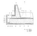
本実施形態において、扉枠体30は、図8に示すように、突出部側補強部材50を有している。この突出部側補強部材50は、突出部40の内側の面に沿って曲げられた曲げ部501を有している。すなわち、突出部側補強部材50は、その断面が、扉枠部材33側へ曲げられたL字形状に構成されている。これによれば、突出部40の強度をさらに増すことができる。(Fourth embodiment)
Next, a fourth embodiment will be described with reference to FIGS.
In the present embodiment, the
また、本実施形態において、扉枠体30は、図7および図8に示すように、枠側補強部材51を有している。この枠側補強部材51は、例えばステンレス鋼やアルミなどの金属製の板をプレス絞り加工することによって構成されている。具体的には、枠側補強部材51は、扉内部材32側が開口した浅い箱状であって、その箱状の底面部分つまり扉外部材31側が、扉外部材31よりもやや小さな矩形状に貫かれた形状に構成されている。つまり、枠側補強部材51は、箱状の周囲を構成する主体部511と、主体部511に対して直角方向に曲げられた曲げ部512とを一体に有して構成されている。これにより、枠側補強部材51は、その断面が、真空断熱パネル34側へ曲げられたL字形状に構成されている。そして、これら主体部511および曲げ部512は、扉枠部材33の内側に収まる矩形の環状に構成されている。 Moreover, in this embodiment, the
また、扉枠部材33は、図8に示すように、係止部52を有している。係止部52は、扉枠部材33の底部332にあって真空断熱パネル34の外周の外側に位置し、扉内部材32側すなわち後方へ突出して設けられている。この係止部52において扉枠部材33の周囲部331側には、後方つまり扉内部材32側へ行くにしたがって周囲部331から離れるような斜面521が形成されている。そして、斜面521と底部332との間には、溝部522が形成されている。この溝部522は、枠側補強部材51の板の厚さ寸法よりもやや大きい溝幅を有している。これに対し、係止部52において斜面521とは反対側の面は、底部332に対してほぼ直角に切り立って構成されている。 Moreover, the
この構成において、枠側補強部材51は、係止部52に対して、後方から前方へ押し込むようにして取付けられる。その際、枠側補強部材51が斜面521に沿って押し込まれると、係止部52は、周囲部331とは反対側へ弾性変形する。これにより、周囲部331と係止部52との間が広がって、周囲部331と係止部52との間に枠側補強部材51が挿入される。周囲部331と係止部52との間に枠側補強部材51が挿入されると、係止部52の変形が戻る。すると、枠側補強部材51の曲げ部512の先端部分は、係止部52の溝部522に入り込んで係止される。このように、枠側補強部材51は、係止部52によって係止されて、扉枠体30の扉枠部材33に固定される。 In this configuration, the frame
これによれば、上記各実施形態と同様の効果を得ることができる。さらに、枠側補強部材51は、その四辺部分が一体に構成されている。このため、一回の取付け作業によって、扉枠体30の四辺部分に枠側補強部材51を取付けることができる。したがって、枠側補強部材51の取付け工数を低減することができ、ひいては断熱箱10の製造コストの低減を図ることができる。 According to this, it is possible to obtain the same effects as those of the above embodiments. Further, the frame-
なお、この第四実施形態において、係止部52は、扉枠部材33の周方向に対して、連続した一個の係止部52としてもよいし、複数の係止部52を間欠的に設けてもよい。
また、上記各実施形態において、反応性ホットメルトに代えて、または反応性ホットメルトと併用して、従来の反応性でないホットメルトを使用することもできる。
さらに、突出部40およびガスケット取付け部41は、必ずしも扉内部材32に一体に構成する必要はなく、別体に構成してもよい。
また、各補強部材35、36、46、50、51は、金属材料に代えて、例えば扉枠部材33に比べて剛性の高い合成樹脂などで構成することもできる。In the fourth embodiment, the locking
In each of the above embodiments, a non-reactive hot melt can be used instead of the reactive hot melt or in combination with the reactive hot melt.
Furthermore, the
Further, each of the reinforcing
以上説明した実施形態によれば、扉枠体の内部の空間に設けられた補強部材は、ネジなどの他の部材によって貫かれることなく扉枠体に固定されている。そのため、補強部材を固定するために、専用の工具を用いて複数箇所のネジ締めなどを行う必要がない。したがって、補強部材の取付け工数が低減され、ひいては断熱箱の製造コストを低減することができる。そして、この場合、補強部材は、ネジなどを使用せずに固定されている。そのため、扉枠体の内部に真空断熱パネルを設けるとともに、その真空断熱パネルの周囲に補強部材を設ける場合であっても、補強部材を固定するネジなどが真空断熱パネルと干渉することがない。したがって、真空断熱パネルは、補強部材を固定するネジなどが接触して破損するおそれがなくなり、これにより、真空断熱パネルを扉枠体の内部に安全に設けることができる。 According to the embodiment described above, the reinforcing member provided in the space inside the door frame body is fixed to the door frame body without being penetrated by other members such as screws. Therefore, in order to fix the reinforcing member, it is not necessary to perform screw tightening at a plurality of locations using a dedicated tool. Therefore, the number of steps for attaching the reinforcing member can be reduced, and as a result, the manufacturing cost of the heat insulation box can be reduced. In this case, the reinforcing member is fixed without using screws or the like. Therefore, even when a vacuum heat insulating panel is provided inside the door frame body and a reinforcing member is provided around the vacuum heat insulating panel, a screw or the like for fixing the reinforcing member does not interfere with the vacuum heat insulating panel. Therefore, the vacuum heat insulation panel can be prevented from being damaged due to contact with a screw or the like for fixing the reinforcing member, whereby the vacuum heat insulation panel can be safely provided inside the door frame.
本発明のいくつかの実施形態を説明したが、これらの実施形態は、例として提示したものであり、発明の範囲を限定することは意図していない。これら新規な実施形態は、その他の様々な形態で実施されることが可能であり、発明の要旨を逸脱しない範囲で、種々の省略、置き換え、変更を行うことができる。これら実施形態やその変更は、発明の範囲や要旨に含まれるとともに、特許請求の範囲に記載された発明とその均等の範囲に含まれる。 Although several embodiments of the present invention have been described, these embodiments are presented by way of example and are not intended to limit the scope of the invention. These novel embodiments can be implemented in various other forms, and various omissions, replacements, and changes can be made without departing from the scope of the invention. These embodiments and modifications thereof are included in the scope and gist of the invention, and are included in the invention described in the claims and the equivalents thereof.
図面中、10は断熱箱、11は箱本体、12、13は冷蔵室扉(扉)、14は野菜室扉(扉)、15は製氷室扉(扉)、16は小冷凍室扉(扉)、17は冷凍室扉(扉)、18は冷蔵室(貯蔵室)、19は野菜室(貯蔵室)、20は製氷室(貯蔵室)、21は小冷凍室(貯蔵室)、22は冷凍室(貯蔵室)、30は扉枠体、34は真空断熱パネル、35は枠側補強部材(補強部材)、352は曲げ部、36は突出部側補強部材(補強部材)、40は突出部、44、45は反応性ホットメルト、46は枠側補強部材(補強部材)、47は前側係止部(係止部)、48は後側係止部(係止部)、50は突出部側補強部材(補強部材)、501は曲げ部、51は枠側補強部材、512は曲げ部、52は係止部を示す。 In the drawings, 10 is a heat insulating box, 11 is a box body, 12 and 13 are refrigerator compartment doors (doors), 14 is a vegetable compartment door (door), 15 is an ice making compartment door (door), and 16 is a small freezer compartment door (door). ), 17 is a freezer compartment door (door), 18 is a refrigerator compartment (storage room), 19 is a vegetable room (storage room), 20 is an ice making room (storage room), 21 is a small freezer room (storage room), 22 is Freezing room (storage room), 30 is a door frame, 34 is a vacuum heat insulation panel, 35 is a frame side reinforcing member (reinforcing member), 352 is a bent portion, 36 is a protruding portion side reinforcing member (reinforcing member), and 40 is protruding , 44 and 45 are reactive hot melts, 46 is a frame side reinforcing member (reinforcing member), 47 is a front locking part (locking part), 48 is a rear locking part (locking part), and 50 is protruding. A side-side reinforcing member (reinforcing member), 501 is a bent portion, 51 is a frame-side reinforcing member, 512 is a bent portion, and 52 is a locking portion.
Claims (6)
Translated fromJapanese前記開口を開閉する扉と、を備え、
前記扉は、
内部に空間が形成された扉枠体と、
前記扉枠体の内部の空間に設けられた真空断熱パネルと、
前記扉枠体の内部の空間にあって前記扉枠体の側面に接して設けられ他の部材によって貫かれることなく接着剤によって前記扉枠体に接着固定された補強部材と、を有していることを特徴とする断熱箱。A box body having a storage chamber and an opening connected to the storage chamber;
A door that opens and closes the opening,
The door
A door frame with a space inside;
A vacuum insulation panel provided in the space inside the door frame,
And have a, and a reinforcing member thatis adhered and fixed to the door frame by an adhesive without being penetrated by the other member is provided in contact with a side surface of the door frame be internal space of the door frame Insulated box characterized by that.
前記補強部材は、前記係止部に係止されて前記扉枠体に固定されていることを特徴とする請求項1または2記載の断熱箱。The door frame has a locking portion that locks the reinforcing member ina state of being separated from the vacuum heat insulating panel ,
The heat insulation box according to claim 1 or 2, wherein the reinforcing member is locked to the locking portion and fixed to the door frame.
前記補強部材は、前記突出部の内部に設けられていることを特徴とする請求項1から5いずれか一項記載の断熱箱。The door frame has a protruding portion that protrudes toward the storage chamber,
The heat insulation box according to any one of claims 1 to 5, wherein the reinforcing member is provided inside the protruding portion.
Priority Applications (1)
| Application Number | Priority Date | Filing Date | Title |
|---|---|---|---|
| JP2011266794AJP5978520B2 (en) | 2011-12-06 | 2011-12-06 | Heat insulation box |
Applications Claiming Priority (1)
| Application Number | Priority Date | Filing Date | Title |
|---|---|---|---|
| JP2011266794AJP5978520B2 (en) | 2011-12-06 | 2011-12-06 | Heat insulation box |
Publications (2)
| Publication Number | Publication Date |
|---|---|
| JP2013119966A JP2013119966A (en) | 2013-06-17 |
| JP5978520B2true JP5978520B2 (en) | 2016-08-24 |
Family
ID=48772689
Family Applications (1)
| Application Number | Title | Priority Date | Filing Date |
|---|---|---|---|
| JP2011266794AActiveJP5978520B2 (en) | 2011-12-06 | 2011-12-06 | Heat insulation box |
Country Status (1)
| Country | Link |
|---|---|
| JP (1) | JP5978520B2 (en) |
Families Citing this family (32)
| Publication number | Priority date | Publication date | Assignee | Title |
|---|---|---|---|---|
| JP2015007498A (en)* | 2013-06-25 | 2015-01-15 | 株式会社東芝 | Refrigerator |
| JP6313035B2 (en)* | 2013-09-24 | 2018-04-18 | 東芝ライフスタイル株式会社 | refrigerator |
| JP6187333B2 (en)* | 2014-03-11 | 2017-08-30 | 三菱電機株式会社 | Storage and refrigerator |
| DE102014214102A1 (en)* | 2014-07-21 | 2016-01-21 | BSH Hausgeräte GmbH | Wall for a household refrigerating appliance, household refrigerating appliances and method for producing a wall |
| KR20170016188A (en) | 2015-08-03 | 2017-02-13 | 엘지전자 주식회사 | Vacuum adiabatic body and refrigerator |
| KR102502160B1 (en) | 2015-08-03 | 2023-02-21 | 엘지전자 주식회사 | Vacuum adiabatic body and refrigerator |
| KR102447245B1 (en) | 2015-08-03 | 2022-09-27 | 엘지전자 주식회사 | Vacuum insulator and refrigerator |
| KR102498210B1 (en) | 2015-08-03 | 2023-02-09 | 엘지전자 주식회사 | Vacuum adiabatic body and refrigerator |
| KR102529853B1 (en) | 2015-08-03 | 2023-05-08 | 엘지전자 주식회사 | Vacuum adiabatic body, fabricating method for the Vacuum adiabatic body, porous substance package, and refrigerator |
| KR102497139B1 (en) | 2015-08-03 | 2023-02-07 | 엘지전자 주식회사 | Vacuum adiabatic body |
| KR102456642B1 (en) | 2015-08-03 | 2022-10-19 | 엘지전자 주식회사 | Vacuum adiabatic body and refrigerator |
| KR102525551B1 (en)* | 2015-08-03 | 2023-04-25 | 엘지전자 주식회사 | Vacuum adiabatic body and refrigerator |
| KR102442973B1 (en) | 2015-08-03 | 2022-09-14 | 엘지전자 주식회사 | Vacuum insulator and refrigerator |
| KR102529852B1 (en)* | 2015-08-03 | 2023-05-08 | 엘지전자 주식회사 | Vacuum adiabatic body and refrigerator |
| KR102525550B1 (en) | 2015-08-03 | 2023-04-25 | 엘지전자 주식회사 | Vacuum adiabatic body and refrigerator |
| KR102466469B1 (en) | 2015-08-03 | 2022-11-11 | 엘지전자 주식회사 | Vacuum adiabatic body and refrigerator |
| CN107923701B (en) | 2015-08-03 | 2020-04-24 | Lg电子株式会社 | Vacuum insulator and refrigerator |
| KR102466470B1 (en) | 2015-08-04 | 2022-11-11 | 엘지전자 주식회사 | Vacuum adiabatic body and refrigerator |
| JP6653553B2 (en)* | 2015-11-11 | 2020-02-26 | シャープ株式会社 | refrigerator |
| JP2018169097A (en)* | 2017-03-30 | 2018-11-01 | パナソニックIpマネジメント株式会社 | Vacuum insulated housing and refrigerator |
| JP7182040B2 (en)* | 2017-03-30 | 2022-12-02 | パナソニックIpマネジメント株式会社 | Vacuum Insulated Enclosures and Refrigerators |
| WO2018181440A1 (en)* | 2017-03-30 | 2018-10-04 | パナソニックIpマネジメント株式会社 | Vacuum heat insulation case and refrigerator using same |
| JP6920633B2 (en)* | 2017-07-10 | 2021-08-18 | パナソニックIpマネジメント株式会社 | Vacuum insulated housing and refrigerator |
| JP2019132507A (en)* | 2018-01-31 | 2019-08-08 | 日立グローバルライフソリューションズ株式会社 | refrigerator |
| CN109708379B (en)* | 2017-10-26 | 2020-10-30 | 日立环球生活方案株式会社 | Refrigerator with a door |
| JP2019138536A (en)* | 2018-02-09 | 2019-08-22 | 日立グローバルライフソリューションズ株式会社 | refrigerator |
| JP6707066B2 (en)* | 2017-10-26 | 2020-06-10 | 日立グローバルライフソリューションズ株式会社 | refrigerator |
| CN108375269A (en)* | 2018-04-02 | 2018-08-07 | 合肥美菱股份有限公司 | A kind of refrigerator door and its manufacturing process |
| KR20200072257A (en) | 2018-12-12 | 2020-06-22 | 엘지전자 주식회사 | Vacuum adiabatic body and refrigerator |
| JP7063974B2 (en)* | 2020-12-01 | 2022-05-09 | 日立グローバルライフソリューションズ株式会社 | refrigerator |
| US11486627B2 (en) | 2020-12-30 | 2022-11-01 | Whirlpool Corporation | Reinforcement assembly for an insulated structure |
| DE102023100214A1 (en)* | 2022-11-28 | 2024-05-29 | Liebherr-Hausgeräte Lienz Gmbh | Refrigerator and/or freezer |
Family Cites Families (11)
| Publication number | Priority date | Publication date | Assignee | Title |
|---|---|---|---|---|
| JPS5225364U (en)* | 1975-08-13 | 1977-02-22 | ||
| JPS581518A (en)* | 1981-06-29 | 1983-01-06 | Nec Home Electronics Ltd | Preparation of vacuum molded parts |
| JPS5830184U (en)* | 1981-08-21 | 1983-02-26 | シャープ株式会社 | refrigerator door |
| JPH0438229Y2 (en)* | 1985-02-25 | 1992-09-08 | ||
| JPH0464086U (en)* | 1990-10-04 | 1992-06-01 | ||
| JPH0559184U (en)* | 1992-01-14 | 1993-08-06 | 三菱電機株式会社 | Insulated door |
| JPH0861834A (en)* | 1994-08-18 | 1996-03-08 | Toshiba Corp | Insulation box and manufacturing method thereof |
| JPH08100991A (en)* | 1994-09-30 | 1996-04-16 | Toshiba Corp | Heat insulation panel manufacturing method |
| JP4120171B2 (en)* | 2000-06-19 | 2008-07-16 | いすゞ自動車株式会社 | Thermal insulation panel |
| JP2003156283A (en)* | 2001-11-20 | 2003-05-30 | Fujitsu General Ltd | refrigerator |
| DE102007029184A1 (en)* | 2007-06-25 | 2009-01-08 | BSH Bosch und Siemens Hausgeräte GmbH | Heat-insulating wall for a refrigeration appliance |
- 2011
- 2011-12-06JPJP2011266794Apatent/JP5978520B2/enactiveActive
Also Published As
| Publication number | Publication date |
|---|---|
| JP2013119966A (en) | 2013-06-17 |
Similar Documents
| Publication | Publication Date | Title |
|---|---|---|
| JP5978520B2 (en) | Heat insulation box | |
| JP6005341B2 (en) | refrigerator | |
| US11047616B2 (en) | Refrigerator and vacuum insulation module thereof | |
| US9696083B2 (en) | Refrigerator | |
| JP5788232B2 (en) | refrigerator | |
| EP2730870B1 (en) | Refrigerator and method of manufacturing inner door thereof | |
| CN103649658B (en) | vacuum insulation element | |
| JP5931355B2 (en) | Heat insulation box | |
| JP5868152B2 (en) | refrigerator | |
| KR20160044842A (en) | Refrigerator and vacuum insulation module thereof | |
| RU2443950C2 (en) | Refrigerator | |
| EP2789948B1 (en) | Refrigerator | |
| JP6964810B2 (en) | refrigerator | |
| TW201335554A (en) | Assembling system of refrigerator and refrigerator | |
| JP7181578B2 (en) | Refrigerator manufacturing method | |
| WO2017183645A1 (en) | Refrigerator | |
| CN113418342A (en) | Door body and refrigerator with same | |
| JP2006220386A (en) | refrigerator | |
| JP5881392B2 (en) | refrigerator | |
| JP3823993B2 (en) | refrigerator | |
| JP5715937B2 (en) | Insulation cabinet | |
| JP6113610B2 (en) | refrigerator | |
| JP2016130631A (en) | Adiabatic box | |
| JP6271124B2 (en) | Manufacturing method of heat insulation box for refrigerator | |
| HK40060026A (en) | Refrigerator |
Legal Events
| Date | Code | Title | Description |
|---|---|---|---|
| A711 | Notification of change in applicant | Free format text:JAPANESE INTERMEDIATE CODE: A712 Effective date:20140204 | |
| A521 | Written amendment | Free format text:JAPANESE INTERMEDIATE CODE: A523 Effective date:20140221 | |
| A621 | Written request for application examination | Free format text:JAPANESE INTERMEDIATE CODE: A621 Effective date:20141010 | |
| A131 | Notification of reasons for refusal | Free format text:JAPANESE INTERMEDIATE CODE: A131 Effective date:20150609 | |
| A977 | Report on retrieval | Free format text:JAPANESE INTERMEDIATE CODE: A971007 Effective date:20150610 | |
| A521 | Written amendment | Free format text:JAPANESE INTERMEDIATE CODE: A523 Effective date:20150806 | |
| A131 | Notification of reasons for refusal | Free format text:JAPANESE INTERMEDIATE CODE: A131 Effective date:20151117 | |
| A521 | Written amendment | Free format text:JAPANESE INTERMEDIATE CODE: A523 Effective date:20160106 | |
| TRDD | Decision of grant or rejection written | ||
| A01 | Written decision to grant a patent or to grant a registration (utility model) | Free format text:JAPANESE INTERMEDIATE CODE: A01 Effective date:20160607 | |
| A711 | Notification of change in applicant | Free format text:JAPANESE INTERMEDIATE CODE: A711 Effective date:20160630 | |
| A61 | First payment of annual fees (during grant procedure) | Free format text:JAPANESE INTERMEDIATE CODE: A61 Effective date:20160706 | |
| R150 | Certificate of patent (=grant) or registration of utility model | Ref document number:5978520 Country of ref document:JP Free format text:JAPANESE INTERMEDIATE CODE: R150 |